1
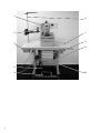
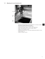
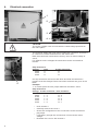
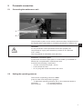
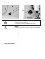
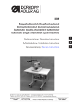
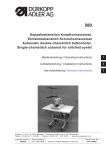
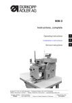
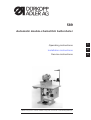
589 Automatic double-chainstitch buttonholer Operating instructions 1 Installation instructions 2 Service instructions 3 Postfach 17 03 51, D-33703 Bielefeld Potsdamer Straße 190, D-33719 Bielefeld Telefon + 49 (0) 5 21 / 9 25-00 Telefax + 49 (0) 5 21 / 9 25 24 35 www.duerkopp-adler.com Anleitung, komplett / Manual, complete 589 Übersicht Summary Bedienanleitung Aufstellanleitung Serviceanleitung Operating instructions Installation instructions Service instructions Bauschaltplan Interconnection-diagram 9870 579020 B 9870 579020 B Postfach 17 03 51, D-33703 Bielefeld • Potsdamer Straße 190, D-33719 Bielefeld Sprache: Deutsch / Englisch Telefon +49 (0) 521 / 9 25-00 • Telefax +49 (0) 5 21 / 9 25 24 35 • www.duerkopp-adler.com Ausgabe / Edition: 07/2003 Printed in Federal Republic of Germany Teile-Nr.:/Part-No.: 0791 589001 Foreword This instruction manual is intended to help the user to become familiar with the machine and take advantage of its application possibilities in accordance with the recommendations. The instruction manual contains important information on how to operate the machine securely, properly and economically. Observation of the instructions eliminates danger, reduces costs for repair and down-times, and increases the reliability and life of the machine. The instruction manual is intended to complement existing national accident prevention and environment protection regulations. The instruction manual must always be available at the machine/sewing unit. The instruction manual must be read and applied by any person that is authorized to work on the machine/sewing unit. This means: – – – Operation, including equipping, troubleshooting during the work cycle, removing of fabric waste, Service (maintenance, inspection, repair) and/or Transport. The user also has to assure that only authorized personnel work on the machine. The user is obliged to check the machine at least once per shift for apparent damages and to immediatly report any changes (including the performance in service), which impair the safety. The user company must ensure that the machine is only operated in perfect working order. Never remove or disable any safety devices. If safety devices need to be removed for equipping, repairing or maintaining, the safety devices must be remounted directly after completion of the maintenance and repair work. Unauthorized modification of the machine rules out liability of the manufacturer for damage resulting from this. Observe all safety and danger recommendations on the machine/unit! The yellow-and-black striped surfaces designate permanend danger areas, eg danger of squashing, cutting, shearing or collision. Besides the recommendations in this instruction manual also observe the general safety and accident prevention regulations! General safety instructions The non-observance of the following safety instructions can cause bodily injuries or damages to the machine. 1. The machine must only be commissioned in full knowledge of the instruction book and operated by persons with appropriate training. 2. Before putting into service also read the safety rules and instructions of the motor supplier. 3. The machine must be used only for the purpose intended. Use of the machine without the safety devices is not permitted. Observe all the relevant safety regulations. 4. When gauge parts are exchanged (e.g. needle, presser foot, needle plate, feed dog and bobbin) when threading, when the workplace is left, and during service work, the machine must be disconnected from the mains by switching off the master switch or disconnecting the mains plug. 5. Daily servicing work must be carried out only by appropriately trained persons. 6. Repairs, conversion and special maintenance work must only be carried out by technicians or persons with appropriate training. 7. For service or repair work on pneumatic systems, disconnect the machine from the compressed air supply system (max. 7-10 bar). Before disconnecting, reduce the pressure of the maintenance unit. Exceptions to this are only adjustments and functions checks made by appropriately trained technicians. 8. Work on the electrical equipment must be carried out only by electricians or appropriately trained persons. 9. Work on parts and systems under electric current is not permitted, except as specified in regulations DIN VDE 0105. 10. Conversion or changes to the machine must be authorized by us and made only in adherence to all safety regulations. 11. For repairs, only replacement parts approved by us must be used. 12. Commissioning of the sewing head is prohibited until such time as the entire sewing unit is found to comply with EC directives. 13. The line cord should be equipped with a country-specific mains plug. This work must be carried out by appropriately trained technicians (see paragraph 8). It is absolutely necessary to respect the safety instructions marked by these signs. Danger of bodily injuries ! Please note also the general safety instructions. Contents Part 2: page: Installation Instructions Class 589 1. Items supplied . . . . . . . . . . . . . . . . . . . . . . . . . . . . . . . . . . . . . . . . . . . . . . . . . . 3 2. General and shipping braces . . . . . . . . . . . . . . . . . . . . . . . . . . . . . . . . . . . . . . . . . 3 3. 3.1 3.2 3.3 Installing the machine Adjusting the working height . . . . . . . . . . . . . . . . . . . . . . . . . . . . . . . . . . . . . . . . . . . 4 Attaching the yarn stand . . . . . . . . . . . . . . . . . . . . . . . . . . . . . . . . . . . . . . . . . . . . . 4 aligning and connecting the pedal . . . . . . . . . . . . . . . . . . . . . . . . . . . . . . . . . . . . . . . . 5 4. Electrical connection . . . . . . . . . . . . . . . . . . . . . . . . . . . . . . . . . . . . . . . . . . . . . . 6 5. 5.1 5.2 Pneumatic connection Connecting the maintenance unit . . . . . . . . . . . . . . . . . . . . . . . . . . . . . . . . . . . . . . . . 7 Setting the operating pressure . . . . . . . . . . . . . . . . . . . . . . . . . . . . . . . . . . . . . . . . . . 7 6. 6.1 Lubrication Filling the oil reservoirs . . . . . . . . . . . . . . . . . . . . . . . . . . . . . . . . . . . . . . . . . . . . . . 8 7. Sewing test . . . . . . . . . . . . . . . . . . . . . . . . . . . . . . . . . . . . . . . . . . . . . . . . . . . . . 9 2 1 6 2 7 8 3 9 4 5 2 10 1. Items supplied What items are supplied depends on your order. Prior to installation please check that all the required parts are present. – 1 head – 2 operating panel – 3 stand – 4 pedal linkage – 5 pedal – 6 yarn stand – 7 table plate – 8 main switch – 9 control box – 10 maintenance unit – optional extras (depending on the order) – tools and minor components in the accessory kit 2. General and shipping braces 2 CAUTION: The machine must be set up by trained specialist personnel. All work on the electrical equipment of this special sewing machine may only be carried out by qualified electricians or other appropriately trained persons. The mains plug must be removed. Shipping braces All shipping braces must be removed before the machine is installed. – Remove safety straps and battens on the machine head, table and stand. 3 3. Installing the machine 1 2 3 3.1 Adjusting the working height The working height is continuously adjustable between 85 and 120 cm (measured to the upper edge of the table plate). – Undo locking screws 1 and 2 on both sides of the stand. – Adjust the table of the machine to the required working height. – Tighten locking screws 1 and 2. 3.2 Attaching the yarn stand 6 6 – 4 3 5 4 – – Insert the reel stand 3 in the hole in the table plate and secure it with the nuts and washers. Fit and align the yarn-reel bracket 5 and unwinding arm 3 as shown in the illustration. NB: the yarn-reel holder and the unwinding arm must be vertically in line. Depending on the type of yarn reel the centring piece 6 must be set as shown in the above illustration. Incorrect settings may lead to faults in operation. 3.3 Aligning and connecting the pedal 1 2 3 4 5 – – – – – – – Align the pedal 4 laterally on the stand brace 5 so that the middle of the pedal is roughly beneath the needle. Screw the pedal 4 firmly to the stand brace. Screw the set value initiator 1 firmly to the stand brace. Attach the pedal linkage 3 to the set value initiator 1. Slightly undo clamping screw 2. Adjust the pedal linkage so that when released the pedal 4 is at an angle of about 10°. Tighten clamping screw 2. 5 2 4. Electrical connection 1 2 3 4 CAUTION: The mains voltage must coincide with the rated voltage specified on the name plate. The machine adapts the local mains voltage via connection terminals 1 to 5 and A to D of the transformers in the control box. Both the transformer terminals are factory-set to a mains voltage of 230 V. For different mains voltages the terminals must be connected as follows: Strip terminal 2: Voltage 200V 230V 240V 5 blue A A A brown-and-white B C D On strip terminal 5 the brown-and-white and blue-and-white wire jumpers must be changed. Both connection terminals are given in the table. Example: “L-4" means place the wire jumper between terminals L and 4. Strip terminal 5: Voltage brown-and-white blue-and-white 190V L-4 N-3 200V L-4 N-2 210V L-4 N-1 220V L-5 N-3 230V L-5 N-2 240V L-5 N-1 – – – – – 6 Undo screws 3. Carefully remove the cover 4. Check the configuration of the connections to the transformer plug strips. If necessary change the connections in line with the mains voltage. Re-attach the cover 4 with screws 3. 5. Pneumatic connection 5.1 Connecting the maintenance unit 1 2 The pneumatic system of the machine and its auxiliary equipment must be supplied with compressed air containing absolutely no water or oil. 2 CAUTION: For the pneumatic control processes to function properly the compressed-air supply must be able to provide air at a pressure of 6 ± 0.5 bar. The compressed-air should be clean (oil-free). Pneumatic connection pack A pneumatic connection pack (item no. 0797 003031) is available for frames with compressed-air maintenance units. It contains the following components: – 5-metre connection hose (Ø = 9 mm) – hose nozzles and ties – R 1/4" plug-and-socket connector with cover 5.2 Setting the operating pressure The machine’s operating pressure is 6 bar. It can be read off at the pressure gauge 2. – To adjust the operating pressure pull up and rotate the handle 2: Clockwise = to increase pressure Anti-clockwise = to decrease pressure. 7 6. Lubrication 1 2 3 4 Caution: danger of injury Oil can cause skin eruptions. Avoid protracted contact with the skin. In the event of contact, thoroughly wash the affected area. CAUTION: The handling and disposal of mineral oils is subject to legal regulation. Deliver used oil to an authorised collection point. Protect your environment. Take care not to spill oil. Use only ESSO SP-NK 10 lubricating oilor an equivalent oil of the following specification: – Viscosity at 40°C: 10 mm²/s – Flashpoint: 150° C This oil is available from DÜRKOPP ADLER AG retail outlets under the following part numbers: 2-litre container: 9047 000013 5-litre container: 9047 000014 6.1 Filling the oil reservoirs – 8 Top up oil reservoirs 2 and 4 to the “max” mark through filler holes 1 and 3. 7. Sewing test A sewing test must be carried out when setting-up is complete. – Insert the mains plug. Caution: danger of injury Turn off the main switch. The needle, looper and gimp threads may only be threaded with the sewing machine switched off. – – – – – – – – Thread the looper thread (see Operating instructions). Thread the needle thread (see Operating instructions). On subclasses with gimp, thread the gimp thread (see Operating instructions). Turn on the main switch. Insert the material to be sewn. Select a buttonhole shape and begin sewing, initially at low speed (see Operating instructions). Gradually increase the speed. Check that the buttonhole meets requirements. 2 If not: – Alter the thread tension (see Operating instructions). 9