1
Gateway
SX2830 Service Guide
SG V1.01
PRINTED IN TAIWAN
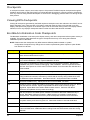
Revision History
Please refer to the table below for the updates made on this service guide.
Date
ii
Version
04-25-2012
First Draft
04-26-2012
V1.00
08-20-2012
V1.01
Chapter
1,2,6
Updates
Phase in Win8 operation system, and update related
information on page1, 15, 16, 98.
Copyright
Copyright © 2012 by Acer Incorporated. All rights reserved. No part of this publication may be reproduced,
transmitted, transcribed, stored in a retrieval system, or translated into any language or computer language, in
any form or by any means, electronic, mechanical, magnetic, optical, chemical, manual or otherwise, without
the prior written permission of Acer Incorporated.
iii
Disclaimer
The information in this guide is subject to change without notice.
Acer Incorporated makes no representations or warranties, either expressed or implied, with respect to the
contents hereof and specifically disclaims any warranties of merchantability or fitness for any particular
purpose. Any Acer Incorporated software described in this manual is sold or licensed "as is". Should the
programs prove defective following their purchase, the buyer (and not Acer Incorporated, its distributor, or its
dealer) assumes the entire cost of all necessary servicing, repair, and any incidental or consequential
damages resulting from any defect in the software.
Acer is a registered trademark of Acer Corporation.
Other brand and product names are trademarks and/or registered trademarks of their respective holders.
iv
Conventions
The following conventions are used in this manual:
SCREEN
MESSAGES
Denotes actual messages that appear on screen.
NOTE
Gives additional information related to the current topic.
WARNING
Alerts you to any physical risk or system damage that might result from doing
or not doing specific actions.
CAUTION
Gives precautionary measures to avoid possible hardware or software
problems.
IMPORTANT
Reminds you to do specific actions relevant to the accomplishment of
procedures.
v
Service Guide Coverage
This Service Guide provides you with all technical information relating to the BASIC CONFIGURATION
decided for Acer's "global" product offering. To better fit local market requirements and enhance product
competitiveness, your regional office MAY have decided to extend the functionality of a machine (e.g. add-on
card, modem, or extra memory capability). These LOCALIZED FEATURES will NOT be covered in this generic
service guide. In such cases, please contact your regional offices or the responsible personnel/channel to
provide you with further technical details.
FRU Information
Please note WHEN ORDERING FRU PARTS, that you should check the most up-to-date information available
on your regional web or channel. If, for whatever reason, a part number change is made, it will not be noted in
the printed Service Guide. For ACER-AUTHORIZED SERVICE PROVIDERS, your Acer office may have a
DIFFERENT part number code to those given in the FRU list of this printed Service Guide. You MUST use the
list provided by your regional Acer office to order FRU parts for repair and service of customer machines.
vi
Table of Contents
System Tour
Features
Block Diagram
System Components
Front Panel
Rear Panel
Hardware Specifications and Configurations
Power Management Function(ACPI support function)
System Utilities
CMOS Setup Utility
Entering CMOS setup
Navigating Through the Setup Utility
Setup Utility Menus
Main for P01-A0(DB.GDE11.001)
Main for P11-A0(DB.GDS11.001)
Advance
Power
Authentication(For Win8 only)
Security
Boot options
Exit
System Disassembly and Assembly
Disassembly Requirements
Pre-disassembly Procedure
Removing the Side Panel
Removing the Front Bezel
Removing the Heat Sink Fan Assembly
Removing the Processor
Removing the HDD-ODD Bracket
Removing the Optical Drive and the Hard Disk Drive
Removing the Wireless Lan Card
Removing the VGA Card
Removing the Memory Modules
Removing the Power Supply
Removing the Mainboard
Removing the Front I/O&USB and Card Reader Boards Assembly
Removing the Top Cover
Removing the Power Switch and LED Cable Assembly
Assembly Requirements
Assembly Procedure
Removing the Side Panel
Removing the HDD-ODD Bracket
Reinstalling the I/O Shielding
Reinstalling the MainBoard
Reinstalling the Power Supply
Reinstalling the Memory
Reinstalling the VGA Card
Reinstalling the Wireless Lan Card
Reinstalling the Optical Drive and the Hard Disk Drive
Reinstalling the HDD-ODD Bracket
1
1
5
6
6
7
8
12
13
13
14
14
15
15
16
17
22
23
24
25
26
27
27
28
29
30
31
34
36
37
41
42
43
44
46
50
53
54
55
56
57
58
59
60
62
64
66
67
68
72
vii
Reinstalling the Processor
Reinstalling the Heat Sink Fan Assembly
Reinstalling the Front Bezel
Reinstalling the Side Panel
System Troubleshooting
Hardware Diagnostic Procedure
System Check Procedures
Power System Check
System External Inspection
System Internal Inspection
Beep Codes
Checkpoints
BIOS Recovery
Jumper and Connector Information
M/B Placement
Jumper Setting
Internal Header Pin Definition
Connector Pin Definition
FRU (Field Replaceable Unit) List
SX2380 Exploded Diagram
SX2380 FRU List
viii
73
75
77
78
79
79
80
80
80
80
81
82
85
86
86
88
89
92
95
96
97
Chapter 1
System Tour
Features
Below is a brief summary of the computer’s many feature:
NOTE: The features listed in this section is for your reference only. The exact configuration of the system
depends on the model purchased.
Operating System
•
Microsoft Windows 8 ML x64
•
Microsoft Windows 8 SL x64
•
Microsoft Windows 7 Home Premium x64
•
Microsoft Windows 7 Home Basic x64
•
Microsoft Windows 7 Home Premium x86
•
Microsoft Windows 7 Home Basic x86
•
Microsoft Windows 7 Starter x86
•
Linpus Xwindows
•
FreeDOS
Processor
•
Socket Type: AMD FM2
•
Socket Quantity: 1
•
Processor Type:
•
AMD Virgo 65W and 100W CPU which supports AMD Turbo Core 3.0 Technology.
Chipset
•
FCH: AMD A75.
PCB
•
DTX, as small as better.
•
4 layer.
•
Acer Inc. logo printed on the PCB.
Memory subsystem
•
Socket Type: DDR III connector .
•
Socket Quantity: 4
•
2 channels, 2 DIMMs per channel, Different colors for DIMM 0 and DIMM 1.
•
Support DDR3 1.5V 1066/1333(1GB / 2GB / 4GB).
•
Max memory of 16GB supported(Using 4GB tech).
•
Dual channel should be enabled always when plug-in 2 same memory size 1.5V DDRIII. memory
module.
•
Follow Follow Acer Mother Board EE Design Request-v5.5-2011-1103 or later version.
Chapter 1
1
Graphics
•
•
HD Graphics Support:
•
Support Digital display HDMI, DVI and VGA.
•
AMD Blu-ray 3D technology support .
•
Complicant with HDMI CTS v1.4a.
•
Dual View function support.
•
Need to measure VGA follow Acer VGA SOP.
•
Support for Cool'n'Quiet™ via FID/VID change.
•
Support for AMD PowerNow!™.
Monitor compatible is requested to the monitor AVL and DQM recommended list.
Graphics card
•
No mechanical retriction to support single slot graphics cards in the PCIe X16 slot.
•
PCIe x 16 should be placed in second slot which is closed to MB boarder.
•
Latch design should be considered to release the latch from CPU side.
Hard disk drive
•
Support up to one SATA ports. 3.5
•
Capacity and models are listed on AVLC
Optical disk drive
•
Support up to one SATA 5.25” standard ODD.
•
Capacity and models are listed on AVLC.
Audio
•
Chip : HD audio codec ALC662 HD codec 5.1
•
Rear 3 jack follow HD audio definition.
•
Front IO: 1*Microphone-in, 1*headphone jack.
Serial ATA controller
•
Connector Type: SATAIII connector.
•
Connector Quantity: 3(3 * 6Gb/s)
•
Storage Type support:
•
3.5” SATAII/SATAIII HDD.
•
DVD-ROM/DVD-RW/DVD+RW/DVD Dual/DVD SuperMultiPlus/ Blu-Ray ODD.
•
AHCI/IDE mode option
•
Default AHCI mode in Microsoft windows OS. Native IDE mode in non-windows OS.
LAN
2
•
Realtek RTL8111FA with surge protection and IOAC support.
•
Meet China Rural PC requirements.
•
Support WOL ,PXE.
•
Need support Wake up on LAN function including from S3,S4,S5, power button off (non-ACPI OS).
•
RJ-45 Back panel port with Link/Activity LEDs.
Chapter 1
Extension slot
•
1 * PCIE x16 (PCIE V2.0).
•
1 * PCIE x1 (PCIE V2.0).
USB Ports
•
Controller: AMD A75 chipset.
•
Rear I/O:
•
•
4 * USB2.0 ports.
•
2 * USB3.0 ports.
Onboard Header:
•
Three 2X5 USB2.0 headers.
•
One 2X10 USB3.0 headers.
•
Connector Pin: standard Intel FPIO pin definition.
•
Cardreader: 1 on borad header should be delegate to cardreader as internal device and use different
color.
•
Data transfer rate support:
•
USB 3.0/2.0/1.1
•
All USB ports must be boot-capable includes USB-ODD, USB-HDD, USB-FDD, and etc…
•
All USB ports must provide the over current protection.
•
Enable the USB EHCI Debug Ports.
Buzzer
•
1 on board buzzer.
Rear I/O connectors
•
1 * PS2 KB+MS.
•
1 * HDMI port.
•
1 * VGA connector.
•
2 * USB 2.0 ports
•
1 * RJ45 + 2 * USB 2.0 ports.
•
2 * USB 3.0 ports.
•
1 * 3 ports Audio jack.
On-board connectors
•
1* FM2 CPU socket.
•
4* DDR3 DIMM Socket.
•
1* PCI Express x16 slot.
•
1* PCI Express x 1 slot.
•
3 * SATAIII ports.
•
Three* 2x5 USB2.0 on board header
•
One* 2x10 USB3.0 on board header
•
One * H5X2 Front Audio Pannel header
•
One* 4 pin PWM CPU Fan connector
•
One* 4 pin System with SAMRT FAN controller (co-lay with 3 pin)
•
One* H1X4 SPDIF out header closed to PCIEx16 slot
Chapter 1
3
•
One* 24 pin ATX interface PS3/PS2 SPS connector
•
One* H2X2 Power Supply Connector
•
One* H7x2 pin front panel IO header
•
One* H3X1 Jumper for clear CMOS
•
One* 3 pin IR receiver header to super I/O
•
One* on board buzzer
•
Two* reserved 2pin GPIO connector
System BIOS
•
•
Type:
•
Use SPI Flash.
•
System BIOS: 8MBytes.
•
BIOS ROM Size: 8MBytes.
Kernel:
•
AMI Kernel with Acer skin/copyright.
Power supply
4
•
Non PFC 220W / PFC 220W / Full range PFC 220W.
•
Support models are listed on AVLC.
Chapter 1
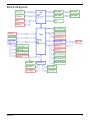
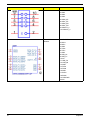
Block Diagram
Chapter 1
5
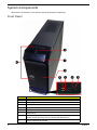
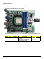
System Components
This section is a virtual tour of the system’s interior and exterior components.
Front Panel
6
No.
Component
1
Gateway logo
2
USB 2.0 ports
3
Card reader slot(SD/SDHC/MMC/Plus)
4
Headphone/Speaker-out/line-out jack
5
Microphone-in jack
6
Optical drive
7
Optical drive eject button
(Press to open drive bay door and access the optical drive.)
8
Power button/power indicator
Chapter 1
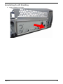
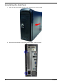
Rear Panel
No.
Chapter 1
Component
1
Line-in jack
2
USB 3.0 ports
3
RJ45 LAN connector
4
PS2 mouse port
5
Power connector
6
PS2 keyboard port
7
HDMI port
8
D-sub port
9
USB 2.0 ports
10
Line-out jack
11
Microphone jack
12
Expansion slot
7
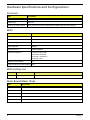
Hardware Specifications and Configurations
Processor
Item
Specification
Processor Type
AMD Virgo 65W and 100W CPU
Socket Type
AMD FM2
Minimum operating speed
0 MHz (If Stop CPU Clock in Sleep State in BIOS Setup is set to Enabled.)
BIOS
Item
Specification
BIOS code programer
AMI Kernel with Acer skin
BIOS version
P01-A0 or P11-A0
BIOS ROM type
SPI Flash
BIOS ROM size
8MByte
Support protocol
SMBIOS(DMI)2.7
Device Boot Support
1st priority: SATA HDD
2nd priority: CD-ROM
3rd priority: USB device
4th priority: LAN
Support to LS-120 drive
No
Support to BIOS boot block feature YES
BIOS Hotkey List
Hotkey
Function
Description
Del
Enter BIOS Setup Utility
Press while the system is booting to enter BIOS Setup Utility.
Main Board Major Chips
Item
Specification
Chipset
AMD A75
USB controller
AMD A75
Audio controller
ALC662-VD
LAN controller
RTL8111FA
SATA controller
AMD A75
8
Chapter 1
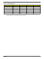
Memory Combinations
Slot
Memory
Total Memory
Slot 1
1GB,2GB,4GB
1G ~4GB
Slot 2
1GB,2GB,4GB
1G ~4GB
Slot 3
1GB,2GB,4GB
1G ~4GB
Slot 4
1GB,2GB,4GB
1G ~4GB
Maximum System Memory Supported
1G~16GB
System Memory
Item
Specification
Memory slot number
4 slot
Support Memory size per socket
1GB/2GB/4GB
Support memory type
DDRIII
Support memory interface
DDRIII 1333/1600MHz
Support memory voltage
1.5V
Support memory module package
240-pin DDRIII
Support to parity check feature
Yes
Support to error correction code (ECC) feature No
Memory module combinations
You can install memory modules in any combination as long as
they match the above specifications.
Audio Interface
Item
Specification
Audio controller
AMD Hudson D2/D3/D4
Audio controller type
ALC662-VD
Audio channel
codec 5.1
Audio function control
Enable/disable by BIOS Setup
Mono or stereo
Stereo
Compatibility
The ALC662-VD supports host audio from Intel chipsets, and also from any
other HDA compatible audio controller. With EAX/Direct Sound 3D/I3DL2
compatibility, software utilities like Karaoke mode, environment emulation,
multi-band software equalizer, 3D positional audio, and optional Dolby R Digital
Live and DTS R CONNECT ™ programs, the ALC662-VD provides an
excellent home entertainment package and game experience for PC users.
Music synthesizer
Yes, internal FM synthesizer.
Sampling rate
192 kHz (max.)
MPU-401 UART support
No
Microphone&Headphone jack
Supported
Chapter 1
9
SATA Interface
Item
Specification
SATA controller
AMD A75
Number of SATA channel
SATAIII X 3(3 * SATA 6Gb/s)
Support mode
AHCI/IDE mode option
USB Port
Item
Specification
Universal HCI
USB 3.0/2.0/1.1
USB Class
Support legacy keyboard for legacy mode
USB Connectors Quantity
USB2.0:
•
Rear IO : 4 ports
•
Internal Header: 6 ports(three 2X5 USB2.0 headers.)
USB3.0:
•
Rear IO: * 2 ports.
•
Internal Header: 2 ports(one 2X10 USB3.0 headers).
Environmental Requirements
Item
Specification
Temperature
Operating
+5°C ~ +35°C
Non-operating
-20 ~ +60°C (Storage package)
Humidity
Operating
15% to 80% RH
Non-operating
10% to 90% RH
Vibration
Operating (unpacked)
10
5 ~ 500 Hz: 2.20g RMS random, 10 minutes per axis in all 3 axes.
5 ~500 Hz: 1.09g RMS random, 1 hour per axis in all 3 axes.
Chapter 1
Power Management
Devices
S1
S3
S4
S5
Power Button
V
V
V
V
USB Keyboard/Mouse
V
V
N/A
N/A
PME
Disabled
Disabled
Disabled
Disabled
RCT
Disabled
Disabled
Disabled
Disabled
WOR
Disabled
Disabled
Disabled
Disabled
•
•
Chapter 1
Devices wake up from S3 should be less than.
Devices wake up from S5 should be less than 10 seconds.
11
Power Management Function(ACPI support function)
Device Standby Mode
•
Independent power management timer for hard disk drive devices(0-15 minutes,time step=1minute).
•
Hard Disk drive goes into Standby mode(for ATA standard interface).
•
Disable V-sync to control the VESA DPMS monitor.
•
Resume method:device activated (keyboard for DOS, keyboard &mouse for Windows.
•
Resume recovery time 3-5sec
Global Standby Mode
•
Global power management timer(2-120minutes,time step=10minute).
•
Hard disk drive goes into Standby mode(for ATA standard interface).
•
Disable H-sync and V-sync signals to control the VESA DPMS monitor.
•
Resume method: Resume to original state by pushing external switch Button,modem ring in,keyboard
an mouse for APM mode.
Resume recovery time :7-10sec
•
Suspend Mode
•
Independent power management timer(2-120minutes,time step=10minute)or pushing extern switch
button.
CPU goes into SMM
•
•
CPU asserts STPCLK# and goes into the Stop Grant State.
•
LED on panel turns amber colour.
•
Hard disk drive goes into SLEEP mode (for ATA standard interface).
•
Disable H-sync and V-sync signals to control the VESA DPMS monitor.
•
Ultra I/O and VGA chip go into power saving mode.
•
Resume method: Resume to original state by pushing external switch Button,modem ring in,keyboard
an mouse for APM mode
•
Return to original state by pushing external switch button,modem ring in and USB keyboard for ACPI
mode.
ACPI
12
•
ACPI specification 1.0b
•
S0,S1,S2 and S5 sleep state support.
•
On board device power management support.
•
On board device configuration support.
Chapter 1
Chapter 2
System Utilities
CMOS Setup Utility
CMOS setup is a hardware configuration program built into the system ROM, called the complementary metaloxide semiconductor (CMOS) Setup Utility. Since most systems are already properly configured and
optimized, there is no need to run this utility. You will need to run this utility under the following conditions.
•
When changing the system configuration settings
•
When redefining the communication ports to prevent any conflicts
•
When modifying the power management configuration
•
When changing the password or making other changes to the security setup
When a configuration error is detected by the system and you are prompted ("Run Setup"
message) to make changes to the CMOS setup
NOTE: If you repeatedly receive Run Setup messages, the battery may be bad. In this case, the system
cannot retain configuration values in CMOS. Ask a qualified technician for assistance.
•
CMOS setup loads the configuration values in a battery-backed nonvolatile memory called CMOS RAM. This
memory area is not part of the system RAM which allows configuration data to be retained when power is
turned off.
Before you run the CMOS Setup Utility, make sure that you have saved all open files. The system reboots
immediately after you close the Setup.
NOTE: CMOS Setup Utility will be simply referred to as “BIOS”, "Setup", or "Setup utility" in this guide.
The screenshots used in this guide display default system values. These values may not be the same
those found in your system.
Chapter 2
13
Entering CMOS setup
1.
Turn on the server and the monitor.
If the server is already turned on, close all open applications, then restart the server.
2.
During POST, press Delete.
If you fail to press Delete before POST is completed, you will need to restart the server.
The Setup Main menu will be displayed showing the Setup’s menu bar. Use the left and right arrow keys
to move between selections on the menu bar.
Navigating Through the Setup Utility
Use the following keys to move around the Setup utility.
•
Left and Right arrow keys – Move between selections on the menu bar.
•
Up and Down arrow keys – Move the cursor to the field you want.
•
PgUp and PgDn keys – Move the cursor to the previous and next page of a multiple page menu.
•
Home – Move the cursor to the first page of a multiple page menu.
•
End – Move the cursor to the last page of a multiple page menu.
+ and - keys – Select a value for the currently selected field (only if it is user-configurable). Press
these keys repeatedly to display each possible entry, or the Enter key to choose from a pop-up
menu.
NOTE: Grayed-out fields are not user-configurable.
•
•
Enter key – Display a submenu screen.
NOTE: Availability of submenu screen is indicated by a (>).
•
14
Esc – If you press this key:
•
On one of the primary menu screens, the Exit menu displays.
•
On a submenu screen, the previous screen displays.
•
When you are making selections from a pop-up menu, closes the pop-up without making a
selection.
•
F1 – Display the General Help panel.
•
F6 – Press to load optimized default system values.
•
F7 – Press to load fail-safe default system values.
•
F10 – Save changes made the Setup and close the utility.
Chapter 2
Setup Utility Menus
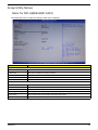
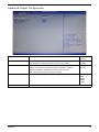
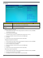
Main for P01-A0(DB.GDE11.001)
The Setup Main menu includes the following main setup categories.
Parameter
Description
System BIOS
Version
Build Date
Processor
Version number of the BIOS setup utility.
Date when the BIOS setup utility was built
Type of CPU installed on the system.
Core Frequency
Core speed of the CPU installed on the system.
Count
Physical CPU count
Memory
Size
Total size of system memory installed on the system.
Product Name
Product name of the system.
System Serial Number
Serial number of the system.
Asset Tag Number
Asset tag number of this system.
System Date
Set the date following the weekday-month-day-year format.
System Time (hh:mm:ss)
Set the system time following the hour-minute-second format.
Chapter 2
15
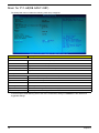
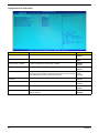
Main for P11-A0(DB.GDS11.001)
The Setup Main menu includes the following main setup categories.
Parameter
Description
System BIOS
Version
Version number of the BIOS setup utility.
Build Date
Date when the BIOS setup utility was built
Processor
Type of CPU installed on the system.
Core Frequency
Core speed of the CPU installed on the system.
Count
Physical CPU count
Memory
Size
Product Name
Total size of system memory installed on the system.
Product name of the system.
System Serial Number
Serial number of the system.
Base Board Serial Number
Serial number of the motherboard.
Asset Tag Number
Asset tag number of this system.
System Date
Set the date following the weekday-month-day-year format.
System Time (hh:mm:ss)
Set the system time following the hour-minute-second format.
In the descriptive table following each of the menu screenshots, settings in boldface are the default and
suggested settings.
16
Chapter 2
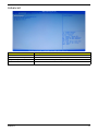
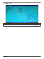
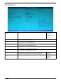
Advanced
Parameter
Description
Miscellaneous
Press Enter to access the Miscellaneous submenu
Advanced Chipset Configuration
Press Enter to access the Advanced Chipset Configuration submenu
Integrated Peripherals
Press Enter to access the Integrated Peripherals submenu
PC Health Status
Press Enter to access the PC Health Status submenu
Chapter 2
17
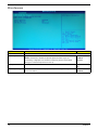
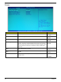
Miscellaneous
Parameter
Description
AHCI Port0/1/2
Displays the status of auto detection of the AHCI device.
Spread Spectrum
Enables or disables the reduction of the mainboard’s EMI.
Note: Remember to disable the Spread Spectrum feature if you are
Option
Enabled
overclocking. A slight jitter can introduce a temporary boost in clock speed
causing the overclocked processor to lock up.
Disabled
Bootup Num-lock
Selects power on state for Num Lock.
On
USB Beep Message
Enables or disables BIOS to display error beeps or messages during USB
device enumeration.
Off
18
Enabled
Disabled
Chapter 2
Advanced Chipset Configuration
AMD Turbo Core
Enables or disables AMD Turbo Core Technology.
Enabled
Disabled
AMD Cooler’n’Quiet
AMD-V
When enabled, this feature allows the OS to reduce power consumption.
Enabled
When disabled, the system operates at maximum CPU speed.
Disabled
Enables or disables the Virtualization Technology (VT) availability. If
enabled, a virtual machine manager (VMM) can utilize the additional
hardware virtualization capabilities provided by this technology.
Enabled
Disabled
Note: A full reset is required to change the setting.
UMA Free Buffer Size
Select the amount of system memory used by the Intel graphics device.
Auto
64MB
128MB
256MB
512MB
Current UMA Size
Chapter 2
Displays the current unified memory architecture (UMA) size.
19
Integrated Peripherals
Parameter
Description
Option
Onboard SATA Controller
Enables or disables the onboard SATA controller.
Enabled
Disabled
Onboard SATA Mode
Select an operating mode for the onboard SATA.
Native IDE
AHCI
Onboard USB Controller
Enables or disables the onboard USB controller.
Enabled
Disabled
Legacy USB Support
Enables or disables support for legacy USB devices.
Enabled
Disabled
USB Storage Emulation
If Auto, USB device equal or less than 2GB will be emulated as Floppy
and remaining as harddrive. Forced FDD option can be used to force a
HDD formatted drive to boot as FDD (Ex.ZIP drive).
Auto
Floppy
Hard Disk
Onboard Graphics
Controller
Enables or disables the onboard Graphics Controller.
Enabled
Disabled
Onboard Audio Controller
Enables or disables the onboard audio controller.
Enabled
Disabled
Onboard LAN Controller
Enables or disables the onboard LAN controller.
Enabled
Disabled
Onboard LAN Option ROM
Enables or disables the load of embedded option ROM for onboard
network controller.
Enabled
Disabled
20
Chapter 2
PC Health Status
Parameter
Description
Option
Smart Fan
Enables or disables the smart system fan control function.
Enabled
Disabled
Chapter 2
21
Power
Parameter
Description
Option
ACPI Suspend Mode
Select an ACPI state.
S3 (STR)
Deep Power Off Mode
Select the Deep power off Mode
S1 (POS)
Enabled
Disabled
RTC Wakeup Support
Enables or Disables to wake up the system by RTC Alarm Function
Enabled
Power On by PCIE Devices
This system can be turned off with a software commend. If you enable
this item, the system can automatically resume if there is an incoming
call on the PCIE LAN card.You must use an ATX power supply in order
to use this feature.Use this item to dowake-up action if inserting the
PCIE card.
Enabled
Wake Up by PS/2 KB/
Mouse
Enables or disables to wake up the system from a power saving mode
using a PS2 keyboard or mouse.
Enabled
Wake Up by USB KB/
Mouse
If enabled, press any key or click the mouse will wake system from S1/
S3 state.
Enabled
Restore On AC Power Loss
Enables or disables the system to reboot after a power failure or
interrupt occurs.
Off
Disabled
Disabled
Disabled
Disabled
On
Last State
22
Chapter 2
Authentication(For Win8 only)
Parameter
Description
Option
Secure Boot
Secure boot flow control, secure boot is possible only if system rens in
user mode.
Enabled
Secure Boot Mode
When standard, fixed secure boot policy.
Standard
When custom, changeable secure boot key databases.
Custom
Chapter 2
Disabled
23
Security
Parameter
Description
Supervisor Password
This item indicates whether a supervisor password has been set. If the password has been
installed, Installed displays. If not, Not Installed displays.
Option
User Password
This item allows you to change user password.
Change Supervisor
Password
You can select this option and press <Enter> to access the sub menu. You can use the sub
menu to change the supervisor password.
Setting a supervisor password
1.
Use the up/down arrow keys to select Change Supervisor Password menu then press Enter.
A password box will appear.
2.
Type a password then press Enter.
The password may consist up to six alphanumeric characters (A-Z, a-z, 0-9)
3.
Retype the password to verify the first entry then press Enter again.
4.
Press F10.
5.
Select Yes to save the new password and close the Setup Utility.
Changing the supervisor password
1.
Use the up/down arrow keys to select Change Supervisor Password menu then press Enter.
2.
Type the original password then press Enter.
3.
Type a new password then press Enter.
4.
Retype the password to verify the first entry then press Enter again.
5.
Press F10.
6.
Select Yes to save the new password and close the Setup Utility.
Removing a supervisor password
24
1.
Use the up/down arrow keys to select Change Supervisor Password menu then press Enter.
2.
Enter the current password then press Enter.
3.
Press Enter twice without entering anything in the password fields.
Chapter 2
Boot Options
1st/2nd/3rd/4th/5th Boot
Device
Specifies the boot order from the available devices.
EFI
Hard Disk
CD^DVD
Removable Device
LAN
EFI Device Priority
Press Enter to access the EFI Device Priority submenu and specify the boot device priority
sequence from available EFI devices.
Hard Disk Drive Priority
Press Enter to access the Hard Disk Drive Priority submenu and specify the boot device
priority sequence from available hard drives.
Optical Disk Drive Priority
Press Enter to access the Optical Disk Drive Priority submenu and specify the boot device
priority sequence from available optical drives.
Removable Device Priority
Press Enter to access the Removable Device Priority submenu and specify the boot device
priority sequence from available removable drives.
Network Device Priority
Press Enter to access the Network Device Priority submenu and specify the boot device
priority sequence from available network drives.
Quiet Boot
When enabled, the BIOS splash screen displays during startup.
Enabled
When disabled, the diagnostic screen displays during startup.
Disabled
Determines whether the system will stop for an error during the POST.
All,but keyboard
Halt On
No Errors
All Errors
Chapter 2
25
Exit
Parameter
Description
Save & Exit Setup
When you have completed the system configuration changes, select this option to leave the
BIOS Setup Utility and reboot the computer, so the new system configuration parameters can
take effect. Select Save & Exit Setup from the Exit menu and press Enter.
Discard Changes and Exit
Setup
Select this option to quit the BIOS Setup Utility without making any permanent changes to the
system configuration, and reboot the computer. Select Discard Changes and Exit Setup
from the Exit menu and press Enter.
Save Changes
Select this option and press Enter to save all the changes and return to the BIOS Setup Utility.
Discard Changes
Use this item enables you to discard any changes that you have made.
Load Default Settings
To set this feature, select Load Default Settings from the Exit menu and press Enter. Then,
select OK to allow the BIOS to automatically load optimal defaults to the BIOS settings. The
Optimal settings are designed for maximum system performance, but may not work best for all
computer applications.
Save as User Default
Settings
Select this option and press Enter to save changes that you have made as user defaults.
Load User Default Settings
Select this option and press Enter to restore user defaults.
26
Chapter 2
Chapter 3
System Disassembly and Assembly
This chapter contains step-by-step procedures on how to disassemble and assembly the desktop computer for
maintenance and troubleshooting.
Disassembly Requirements
To disassemble the computer, you need the following tools:
•
Wrist grounding strap and conductive mat for preventing electrostatic discharge
•
Flat-blade screwdriver
•
Philips screwdriver
•
Hex screwdriver
•
Plastic flat-blade screwdriver
•
Plastic tweezers
NOTE: The screws for the different components vary in size. During the disassembly process, group the
screws with the corresponding components to avoid mismatch when putting back the components.
chapter 3
27
Pre-disassembly Procedure
Before proceeding with the disassembly procedure, perform the steps listed below:
28
1.
Turn off the system and all the peripherals connected to it.
2.
Unplug the power cord from the power outlets.
3.
Unplug the power cord from the system.
4.
Unplug all peripheral cables from the system.
5.
Place the system unit on a flat, stable surface.
Chapter 3
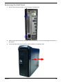
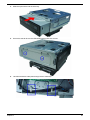
Removing the Side Panel
1.
Remove the two screws located on the rear edge of the side panel.
2.
Slide the side panel toward the back of the chassis until the tabs on the cover disengage with the slots on
the chassis.
3.
Lift the side panel away from the server and put it aside for reinstallation later.
Chapter 3
29
Removing the Front Bezel
30
1.
Release the front bezel retention tabs from the chassis interior.
2.
Pull the bezel away from the chassis.
Chapter 3
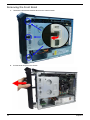
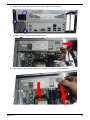
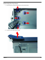
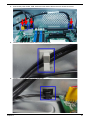
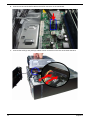
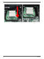
Removing the Heat Sink Fan Assembly
WARNING:The heat sink becomes very hot when the system is on. NEVER touch the heat sink with any metal
or with your hands.
1.
Loosen the hook of heat sink as shown below.
2.
Disconnect tache of heat sink away from the retention frame.
Chapter 3
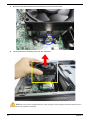
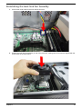
31
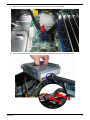
3.
Disconnect the other end tache of heat sink away from the retention frame.
4.
Lift the heat sink fan assembly away from the mainboard.
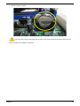
Note:CPU Fan has been highlighted with the yellow rectangle as above image shows.Please detach the CPU
Fan and follow local regulations for disposal.
32
Chapter 3
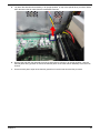
5.
Lay down the heat sink fan assembly, in an upright position, on top of the optical drivey, as shown below,
then disconnect the fan cable from the mainboard connector.
6.
Remove the heat sink fan assembly from the chassis then lay it down in an upright position—with the
thermal patch facing upward. Do not let the thermal patch on the heat sink fan assembly touch the work
surface.
7.
Use an alcohol pad to wipe off the thermal grease from both the heat sink and the processor.
Chapter 3
33
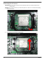
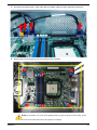
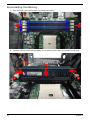
Removing the Processor
IMPORTANT:Before removing a processor from the mainboard, make sure to create a backup file of all
important data.
WARNING:The processor becomes very hot when the system is on. Allow it to cool off first before handling.
34
1.
Release the load lever.
2.
Lift the load lever to the fully open, upright position.
Chapter 3
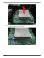
3.
Pull out the processor from the socket.
IMPORTANT: If you are going to install a new processor, note the arrow on the corner to make sure the
processor is properly oriented over the socket.
Chapter 3
35
Removing the HDD-ODD Bracket
36
1.
Remove the two screws that secure the HDD-ODD bracket to the chassis.
2.
Lift the bracket up.
Chapter 3
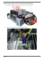
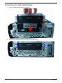
Removing the Optical Drive and the Hard Disk Drive
1.
Disconnect the SATA (1) and power (2) cables from the rear of the hard disk drive.
2.
Disconnect the other end of the SATA cable from the mainboard.
Chapter 3
37
38
3.
Disconnect the SATA (2) and power (1) cables from the rear of the optical drive.
4.
Disconnect the other end of the SATA cable from the mainboard.
Chapter 3
5.
Remove the screws that secure the optical drive to the HDD-ODD bracket.
6.
Pull the optical drive out of the drive bay.
Chapter 3
39
40
7.
Remove the four screws that secure the hard disk drive to the HDD bracket.
8.
Slide the hard disk drive out of the bracket.
Chapter 3
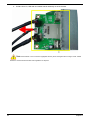
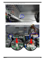
Removing the Wireless Lan Card
1.
Remove the screw from the expansion board bracket opposite the PCIE1X 1 slot.
2.
Gently pull up the expansion board (1), move it slightly to the left and remove (2) from the slot.
Note:Circuit boards >10 cm² has been highlighted with the yellow rectangle as above image shows. Please
detach the Circuit boards and follow local regulations for disposal.
Chapter 3
41
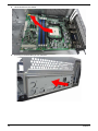
Removing the VGA Card
1.
Remove the screws that secures the card to the chassis.
2.
Gently pull the card to remove it from the mainboard.
Note:Circuit boards >10 cm² has been highlighted with the yellow rectangle as above image shows. Please
detach the Circuit boards and follow local regulations for disposal.
42
Chapter 3
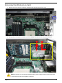
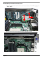
Removing the Memory Modules
IMPORTANT:Before removing any DIMM from the memory board, make sure to create a backup file of all
important data.
1.
Press the holding clips on both sides of the DIMM slot outward to release the DIMM(1).
2.
Gently pull the DIMM upward to pull it away from the M/B(2).
Note:Circuit boards >10 cm² has been highlighted with the yellow rectangle as above image shows. Please
detach the Circuit boards and follow local regulations for disposal.
3.
Repeat steps 1 and 2 to remove the second memory module from the DIMM2, DIMM3, DIMM4 slot.
Chapter 3
43
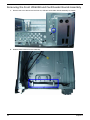
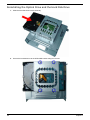
Removing the Power Supply
1.
2.
44
Disconnect the ATX power supply cables from its mainboard connector.
a.
Squeeze on the retaining latch (1) attached to the cable end of the connector.
b.
Grasp the cable end of the connector and pull it straight up (2).
Remove the screw that secures the power supply to the chassis.
Chapter 3
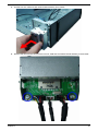
3.
Remove the three screws that secure the power supply to the rear panel.
4.
Pull the the power supply module toward the right.
5.
Tilt the power supply module slightly to the outside(1) and lift it out of the chassis(2).
Chapter 3
45
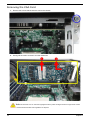
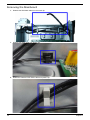
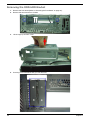
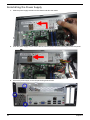
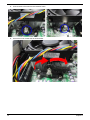
Removing the Mainboard
46
1.
Release the HDD data cable from the metal clip.
1.
Release the audio cable from plastic clip.
2.
Releas the USB and card reader cable from plastic clip.
Chapter 3
3.
Dsconnect the power switch, USB, Audio and card reader cable from their mainboard connectors.
4.
Remove the six screws that secure the mainboard to the chassis.
Note:Circuit boards >10 cm² has been highlighted with the yellow rectangle as above image
shows.
Please detach the Circuit boards and follow local regulations for disposal.
Chapter 3
47
48
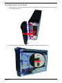
5.
Lift the board from the chassis.
6.
Punching in IO Shield then you can remove it.
Chapter 3
7.
Remove the RTC battery.
Note:RTC battery has been highlighted with the yellow circle as above image shows.Please detach the RTC
battery and follow local regulations for disposal.
Chapter 3
49
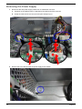
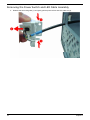
Removing the Front I/O&USB and Card Reader Boards Assembly
50
1.
Remove the screw that secure the front I/O, USB and card reader boards assembly to chassis.
2.
Release these cables from the metal clip.
Chapter 3
3.
Pull the front I/O, USB and card reader boards assembly from chassis.
4.
Remove the two screws that secure the front I/O, USB and card reader boards assembly to the bracket.
Chapter 3
51
c.
Pull tthe front I/O, USB and card reader boards assembly out of the bracket.
Note:Circuit boards >10 cm² has been highlighted with the yellow rectangle as above image
shows. Please
detach the Circuit boards and follow local regulations for disposal.
52
Chapter 3
Removing the Top Cover
1.
Gently release the top bezel retention tabs from the chassis interior.
2.
Pull the top cover away from the chassis.
Chapter 3
53
Removing the Power Switch and LED Cable Assembly
1.
54
Release the two locking tabs (1) and gently pull the power switch and LED cable out (2).
Chapter 3
Assembly Requirements
To assemble the computer, you need the following tools:
•
Wrist grounding strap and conductive mat for preventing electrostatic discharge
•
Flat-blade screwdriver
•
Philips screwdriver
•
Hex screwdriver
•
Plastic flat-blade screwdriver
•
Plastic tweezers
NOTE: The screws for the different components vary in size. During the assembly process, group the screws
with the corresponding components to avoid mismatch when putting back the components.
Chapter 3
55
Assembly Procedure
Before proceeding with the assembly procedure, perform the steps listed below:
56
1.
Turn off the system and all the peripherals connected to it.
2.
Unplug the power cord from the power outlets.
3.
Unplug the power cord from the system.
4.
Unplug all peripheral cables from the system.
5.
Place the system unit on a flat, stable surface.
Chapter 3
Removing the Side Panel
1.
Remove the two screws located on the rear edge of the side panel.
2.
Slide the side panel toward the back of the chassis until the tabs on the cover disengage with the slots on
the chassis.
3.
Lift the side panel away from the server and put it aside for reinstallation later.
Chapter 3
57
Removing the ODD-HDD Bracket
58
1.
Remove the front bezel.(Refer to “Removing the Front Bezel” on page 27).
2.
Remove the two screws from chassis.
3.
Lift the cage up and turn it over.
4.
Punching in PCI Shelf slice then you can remove it.
Chapter 3
Reinstalling the I/O Shielding
1.
Install I/O shielding into chassis.
Chapter 3
59
Reinstalling the Main Board
60
1.
Slide the mainboard into the chassis, with the I/O ports of the mainboard extruding from their port holes,
then lower the mainboard in place.
2.
Make sure the screw holes on the main board are aligned with those on the chassis. Secure the
mainboard with four screws.
Chapter 3
3.
Connect the power switch, USB, Audio and card reader cable to the main board connectors.
4.
Install the USB and card reader cable into the plastic clip.
5.
Install the front audio cable into the plastic clip.
Chapter 3
61
Reinstalling the Power Supply
62
1.
Slide the power supply module into the chassis and tilt to the inside.
2.
Push the power supply module toward the left, with the power connector extruding from the rear panel.
3.
Secure the power supply to the rear panel using three screws.
Chapter 3
4.
Secure the power supply to the chassis using the screw.
5.
Connect the ATX 24Pin Power cable and ATX 4Pin Power cable to main board.
Chapter 3
63
Reinnstalling the Memory
64
1.
Open the holding clips on both sides of the DIMM slot outward.
2.
Insert the memory module into the DIMM1 slot (1) and then press it down until it clicks into place (2).
Chapter 3
3.
If a second memory module is available, install it in the DIMM2 slot by repeating step 1.
NOTE: Install memory rule as table shown below.
DIMM1
DIMM3
DIMM2
DIMM4
A
A
A
A
B
B
A
B
A
A
A
A
B
A
A
A
A
A
A
B
A
B
Remark:A and B show different size of memory, size:A>B
Chapter 3
65
Reinstalling the VGA Card
66
1.
Position the expansion board over the PCIE16X 1 slot and move it slightly to the right (1), making sure the
card guide is aligned with the slot guide on the chassis. Insert the expansion card properly connector into
PCIE16X 1 slot (2).
2.
Secure the expansion board bracket opposite the PCIE16X 1 slot using one screw.
Chapter 3
Reinstalling the Wireless Lan Card
1.
Position the expansion board over the PCIE1X 1 slot and move it slightly to the right (1), making sure the
card guide is aligned with the slot guide on the chassis. Insert the expansion card connector properly into
PCIE1X 1 slot (2).
2.
Secure the expansion board bracket opposite the PCIE1X 1 slot using one screw.
Chapter 3
67
Reinstalling the Optical Drive and the Hard Disk Drive
68
1.
Slide the hard disk drive into the drive bay.
2.
Secure the hard disk drive to the HDD-ODD bracket using four screws.
Chapter 3
3.
Slide the optical drive into the drive bay.
4.
Secure the optical drive to the HDD-ODD bracket using two screws.
5.
Let HDD SATA data cable pass through the two metal clip.
Chapter 3
69
70
6.
Connect one end of the SATA cable to the SATA connector on the mainboard.
7.
Connect the SATA(1) and power(2) cables to their connectors on the rear of the hard disk drive.
Chapter 3
8.
Connect one end of the SATA cable to the SATA connector on the mainboard.
9.
Connect the SATA(1) and power(2) cables to their connectors on the rear of the optical drive.
Chapter 3
71
Reinstalling the HDD-ODD Bracket
72
1.
Install the HDD-ODD bracket into the chassis.
2.
Secure the HDD-ODD bracket to the chassis using two screws.
Chapter 3
Reinstalling the Processor
IMPORTANT:If you are going to install a new processor, note the arrow on the corner to make sure the
processor is properly oriented over the socket.
1.
Release the load lever, lift the load lever to the fully open, gently put the processor into the socket.
Chapter 3
73
2.
74
Close the load lever to its latch.
Chapter 3
Reinstalling the Heat Sink Fan Assembly
1.
Connect the cooler cable to the main board connector.
2.
Position the heat sink fan assembly on top of the processor, making sure the screws are aligned with the
screw holes on the main board.
Chapter 3
75
76
3.
Connect tache of heat sink to the retention frame.
4.
Secure the hook of heat sink as shown below.
Chapter 3
Reinstalling the Front Bezel
1.
Insert the tabs on the front bezel into the notches on the left side of the chassis and attach the front bezel
in the direction indicated.
2.
Make sure the front bezel retention tabs are securedly fastened to the chassis interior.
Chapter 3
77
Reinstalling the Side Panel
78
1.
Push the side panel toward the front of the chassis until it is firmly closed.
2.
Secure the side panel to the rear edge of the chassis using two screws.
Chapter 3
Chapter 4
System Troubleshooting
This chapter provides instructions on how to troubleshoot system hardware problems.
Hardware Diagnostic Procedure
IMPORTANT:The diagnostic tests described in this chapter are only intended to test Acer products. NonAcerproducts, prototype cards, or modified options can give false errors and invalid
systemresponses.
1.
Obtain the failing symptoms in as much detail as possible.
2.
Verify the symptoms by attempting to recreate the failure by running the diagnostic tests or repeating
thesame operation.
3.
Refer to “Power System check” on page 80 and “Beep Codes” on page 81 to determine which corrective
action to perform.
Chapter 4
79
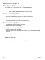
System Check Procedures
Power System Check
If the system will power on, skip this section. Refer to System External Inspection.
If the system will not power on, do the following:
•
Check if the power cable is properly connected to the system and AC source.
•
Check if the voltage selector switchis set to the correct voltage setting.
System External Inspection
1.
Inspect the LED indicators on the front panel, which can indicate the malfunction.
2.
Make sure that air flow is not blocked.
3.
Make sure nothing in the system is making contact that could short out power.
4.
If the problem is not evident, continue with System Internal Inspection.
System Internal Inspection
1.
Turn off the system and all the peripherals connected to it.
2.
Unplug the power cord from the power outlets.
3.
Unplug the power cord from the system.
4.
Unplug all peripheral cables from the system.
5.
Place the system unit on a flat, stable surface.
6.
Remove the system covers.For instructions on removing system covers, refer to “System Disassembly”
on page 27.
7.
Verify that components are properly seated.
8.
Verify that all cable connectors inside the system are firmly and correctly attached to their appropriate
connectors.
9.
Verify that all components are Acer-qualified and supported.
10. Replace the system covers.
11. Power on the system.
12. If the problem with the system is not evident, you can try viewing the POST messages and BIOS event
logs during the system startup.
80
Chapter 4
Beep Codes
Beep codes are used by the BIOS to indicate a serious or fatal error to the end user. Beep codes are used
when an error occurs before the system video has been initialized. Beep codes will be generated by the
system board speaker, commonly referred to as the PC speaker.
AMIBIOS displays the checkpoints in the bottom right corner of the screen during POST. This display method
is limited, since it only displays checkpoints that occur after the video card has been activated.
Not all computers using AMIBIOS enable this feature. In most cases, a checkpoint card is the best tool for
viewing AMIBIOS checkpoints.
Beep Symptom
Cause and Description
One short beep
System is ready.
System is OK.
Continuous one long beep
Memory not installed or memory error.
One long beep and two short beeps then
repeat.
VGA not installed or VGA error.
Graphics card error/not installed, graphics card memory
error or graphics card BIOS checksum error.
One long beep then two short beep
BIOS damaged.
BIOS is damaged, BIOS POST jumps to Boot Block to
execute the default procedures.
Two short beeps
CMOS damaged.
CMOS checksum error or CMOS battery loss occurs.
Chapter 4
81
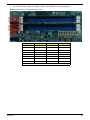
Checkpoints
A checkpoint is either a byte or word value output to I/O port 80h.The BIOS outputs checkpoints throughout
bootblock and Power-On Self Test (POST) to indicate the task the system is currently executing. Checkpoint
sare very useful in aiding software developers or technicians in debugging problems that occur during the preboot process.
Viewing BIOS checkpoints
Viewing all checkpoints generated by the BIOS requires acheckpoint card, also referred to as a POST card or
POST diagnostic card. These are ISA or PCI add-in cards that show the value of I/O port 80h on a LED
display. Checkpoints may appear on the bottom right corner of the screen during POST. This display method
islimited, since it only displays checkpoints thatoccur after the video card has been activated.
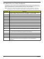
Bootblock Initialization Code Checkpoints
The Bootblock initialization code sets up the chipset,memory, and other components before system memory is
available. The following table describes the type of checkpoints that may occur during the bootblock
initialization portion of the BIOS.
NOTE: Please note that checkpoints may differ between different platforms based on system
configuration.Checkpoints may change due to vendor requirements,system chipset or option ROMs
from add-in PCI devices.
Checkpoint
Description
Before D0
If boot block debugger is enabled, CPU cache-as-RAM functionality is enabled at this point.
Stack will be enabled from this point.
D0
Early Boot Strap Processor (BSP) initialization like microcode update, frequency and other
CPU critical initialization. Early chipset initialization is done.
D1
Early super I/O initialization is done including RTC and keyboard controller. Serial port is
enabled at this point if needed for debugging. NMI is disabled. Perform keyboard controller
BAT test. Save power-on CPUID value in scratch CMOS. Go to flat mode with 4GB limit and
GA20 enabled.
D2
Verify the boot block checksum. System will hang here if checksum is bad.
D3
Disable CACHE before memory detection. Execute full memory sizing module. If memory
sizing module not executed, start memory refresh and do memory sizing in Boot block code.
Do additional chipset initialization. Re-enable CACHE. Verify that flat mode is enabled.
D4
Test base 512KB memory. Adjust policies and cache first 8MB. Set stack.
D5
Bootblock code is copied from ROM to lower system memory and control is given to it. BIOS
now executes out of RAM. Copies compressed boot block code to memory in right
segments. Copies BIOS from ROM to RAM for faster access. Performs main BIOS
checksum and updates recovery status accordingly.
D6
Both key sequence and OEM specific method is checked to determine if BIOSrecovery is
forced. Main BIOS checksum is tested. If BIOS recovery is necessary,control flows to
checkpoint E0. See Bootblock Recovery Code Checkpoints sectionfor more information.
D7
Restore CPUID value back into register. The Bootblock-Runtime interface module is moved
to system memory and control is given to it. Determine whether to execute serial flash.
D8
The Runtime module is uncompressed into memory. CPUID information is stored in memory.
D9
Store the Uncompressed pointer for future use in PMM. Copying Main BIOS into memory.
Leaves all RAM below 1MB Read-Write including E000 and F000 shadow areas but closing
SMRAM.
82
Chapter 4
Checkpoint
Description
DA
Restore CPUID value back into register. Give control to BIOS POST (ExecutePOSTKernel).
See POST Code Checkpoints section of document for more information.
DC
System is waking from ACPI S3 state.
E1-E8 ECEE
OEM memory detection/configuration error. This range is reserved for chipset vendors &
system manufacturers. The error associated with this value may be different from one
platform to the next.
Chapter 4
83
Bootblock Recovery Code Checkpoints
The Bootblock recovery code gets control when the BIOS determines that a BIOS recovery needs to occur
because the user has forced the update or the BIOS checksum is corrupt. The following table describes the
type of checkpoints that may occur during the Bootblock recovery portion of the BIOS.
NOTE: Checkpoints may differ between different platforms based on system configuration. Checkpoints
maychange due to vendor requirements, system chipset or option ROMs from add-in PCI devices.
Checkpoint
Description
E0
Initialize the floppy controller in the super I/O. Some interrupt vectors are initialized. DMA
controller is initialized. 8259 interrupt controller is initialized. L1 cache is enabled.
E9
Set up floppy controller and data. Attempt to read from floppy.
EA
Enable ATAPI hardware. Attempt to read from ARMD and ATAPI CDROM.
EB
Disable ATAPI hardware. Jump back to checkpoint E9.
EF
Read error occurred on media. Jump back to checkpoint EB.
F0
Search for pre-defined recovery file name in root directory.
F1
Recovery file not found.
F2
Start reading FAT table and analyze FAT to find the clusters occupied by the recovery file.
F3
Start reading the recovery file cluster by cluster.
F5
Disable L1 cache.
FA
Check the validity of the recovery file configuration to the current configuration of the flash
part.
FB
Make flash write enabled through chipset and OEM specific method. Detect proper flash
part. Verify that the found flash part size equals the recovery file size.
F4
The recovery file size does not equal the found flash part size.
FC
Erase the flash part
FD
Program the flash part.
FF
The flash has been updated successfully. Make flash write disabled. Disable ATAPI
hardware. Restore CPUID value back into register. Give control to F000 ROM at
F000:FFF0h.
84
Chapter 4
BIOS Recovery
AMIBIOS supports a "recovery flash" mode, which can be used to flash update a BIOS from the boot block.
This is used to update a BIOS image without the need to boot to an operating system. The following is the
process that user should follow to flash BIOS ROM.
1.
Put the AMIBoot.ROM to a bootable USB flash drive(Disk on Key, DOK).
2.
Install the DOK to the system.
3.
Press power button to boot the system and then press Ctrl + Home.
4.
The BIOS recovery function will be executed.
5.
After BIOS is updated completely, the system will auto reboot.
6.
Please enter the setup menu to load default after system reboot.
Chapter 4
85
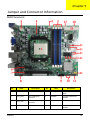
Chapter 5
Jumper and Connector Information
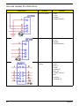
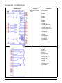
M/B Placement
No
Label
Description
No
Label
Description
1
CPU Socket
AMD FM2
2
DIMM1~4
240-pin DDR3 SDRAM
slots
3
CPU_FAN
CPU cooling fan
connector
4
PWMIC
Firmware download
header
5
ATX_12V
Auxiliary 4-pin power
connector
6
PCIEX1
PCI Express X1 slot
7
PCIEX16
PCI Express X16 slot
8
AUDIO
Front panel audio
header
Chapter 5
86
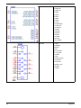
No
87
Label
Description
No
Label
Description
9
USB3.0
Front panel USB3.0
header
10
USB2.0
Front panel USB2.0
header
11
PANEL
Front panel switch/
LED header
12
SATA1~3
Serial ATA connectors
13
GPIO
GPIO 1x2 pin
14
CLR_CMOS
Clear COMS jumper
15
Debug Port
Debug card
16
ATX_POWER
Standard 24-pin ATX
power connector
17
System FAN
System cooling fan
connector
18
IR Reciever
Infrared header
Chapter 5
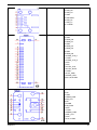
Jumper Setting
This section explains how to set the jumper for correct configuration of the main board.
Jumpers with more than one pin are numbered. When setting a jumper, ensure that the jumper caps are
placed on the correct pins.
The following illustration shows the location of CLR_CMOS.
The following table shows the settings of the 3-pin CLR_CMOS jumper. Place the jumper cap on pins 1 and 2
to close or short the jumper. Place the jumper cap on pins 2 and 3 to open or clear CMOS.
Jumper
Type
CMOS1
3-pin
Chapter 5
Description
Clear CMOS
Setting (default)
1-2: Close (default)
2-3: Open
Before clearing the CMOS, make
sure to turn off the system.
88
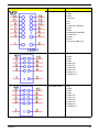
Internal Header Pin Definition
Header Name
89
Function
Definition
CPU Fan Header
1:GND
2:+12V
3:SENSE
4:PWM CONTROL
System Fan Header
1:GND
2:+12V
3:SENSE
4:PWM CONTROL
Front Panel Audio
Header
1:MIC_L
2:GND
3:MIC_R
4:PWR
5:FRONT_R
6:MIC_JD
7:FRONT_SENCE
8:NC
9:FRONT_L
10:FRONT_JD
Chapter 5
Header Name
Chapter 5
Function
Definition
Front panel Header
1:NC
2:GND
3:SB5V
4:LAN LED
5:NC
6:NC
7:PWR RST CONTROL
8:GND
9:GND
10:PWR BTN CONTROL
11:SATA LED
12:GND
13:VCC
14:VCC5 for HDD LED
Front USB Header
1:NC
2:GND
3:GND
4:GND
5:USB0_XP
6:USB1_XP
7:USB0_XN
8:USB1_XN
9:USBVCC_0
10:USBVCC_0
Front USB Header
1:NC
2:GND
3:GND
4:GND
5:USB0_XP
6:USB1_XP
7:USB0_XN
8:USB1_XN
9:USBVCC_1
10:USBVCC_1
90
Header Name
91
Function
Definition
Front USB Header
1:NC
2:GND
3:GND
4:GND
5:USB0_XP
6:USB1_XP
7:USB0_XN
8:USB1_XN
9:USBVCC_2
10:USBVCC_2
Front USB3.0
Header
1:USB PWR
2:RXN1
3:RXP1
4:GND
5:TXN1
6:TXP1
7:GND
8:USB_N1
9:USB_P1
10:OC
11:USB_P2
12:USB_N2
13:GND
14:TXP2
15:TXN2
16:GND
17:RXP2
18:RXN2
19:USB PWR
20:NC
Chapter 5
Connector Pin Definition
Header Name
Chapter 5
Function
Definition
RJ45 and 2 PORT
USB
1:LAN PWR
2:MDI0+
3:MDI04:MDI1+
5:MDI16:MDI2+
7:MDI28:MDI3+
9:MDI310:GND
11:LAN_ACT_LED12:LAN_ACT_LED+
13:LINK_100_LEDJ
14:LINK_1000_LEDJ
15:USB PWR
16:USB_N1
17:USB_P1
18:GND
19:USB PWR
20:USB_N0
21:USB_P0
22~30:GND
ADUIO JACK
1:GND
2:MIC_R
3:GND
4:MIC_JD
5:MIC_L
22:LINE_IN_R
23:GND
24:LINE_IN_JD
25:LINE_IN_L
32:LINE_OUT_R
33:GND
34:LINE_OUT_JD
35:LINE_OUT_L
G1~4:GND
NP1:NC
92
93
USB3.0 CONN
1:USB PWR
2:USB_N0
3:USB_P0
4:GND
5:RXN1
6:RXP1
7:GND
8:TXN1
9:TXP110:USB PWR
11:USB_N1
12:USB_P1
13:GND
14:RXN2
15:RXP2
16:GND
17:TXN2
18:TXP2
19~22:GND
D-SUB
1:RED
2:GREEN
3:BLUE
4:NC
5,6,7,8:GND
9:+5V_VGA
10:GND
11:NC
12:DDC_DATA
13:HSYNC
14:VSYNC
15:DDC_CLK
16:GND
17:GND
Chapter 5
Chapter 5
USB CONN
1:USB PWR
2:USB_N0
3:USB_P0
4:GND
5:USB PWR
6:USB_N1
7:USB_P1
8~12:GND
HDMI
1:HDMI_P0
2:GND
3:HDMI_N0
4:HDMI_P1
5:GND
6:HDMI_N1
7:HDMI_P2
8:GND
9:HDMI_N2
10:HDMI_CLK_P
11:GND
12:HDMI_CLK_N
13:NC
14:NC
15:CTRL_CLK
16:CTRL_DATA
17:GND
18:+5V_PWR
19:DDSP_HPD
20,21,22,23:GND
PS2 KB/MS
1:MS_DATA
2:NC
3:GND
4:KBMS_PWR
5:MS_CLK
6:NC
7/8:GND
9:KB_DATA
10:NC
11:GND
12:KBMS_PWR
13:KB _CLK
14:NC
15,16,17:GND
94
Chapter 6
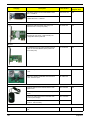
FRU (Field Replaceable Unit) List
This chapter offers the FRU (Field Replaceable Unit) list in global configuration of the SX2380 desktop
computer. Refer to this chapter whenever ordering the parts to repair or for RMA (Return Merchandise
Authorization).
NOTES:
chapter 6
•
When ordering FRU parts, check the most up-to-date information available on your regional web
or channel. For whatever reasons a part number is changed, it will NOT be noted on the printed
Service Guide. For Acer authorized service providers, your Acer office may have a different part
number code from those given in the FRU list of this printed Service Guide. You MUST use the
local FRU list provided by your regional Acer office to order FRU parts for service.
•
To scrap or to return the defective parts, follow the local government ordinance or regulations on
how to dispose it properly, or follow the rules set by your regional Acer office on how to return it.
•
This document will be updated as more information about the FRU list becomes available.
95
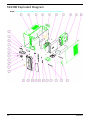
SX2380 Exploded Diagram
NOTE: This section will be updated when more information becomes available.
96
Chapter 6
ITEM
NAME
Q’TY
ITEM
NAME
Q’TY
1
CHASSIS-BOTTOM-P5-8_5L
1
17
P5-8_5L-ODD-BUTTON-POLE
1
2
U-CHASSIS-HX097-P5-8_5L
1
18
P5-8_5L-ODD-DOOR
1
3
MB
1
19
ODD-DOOR-SPRING
2
4
HDD
1
20
P5-8_5L-ODD-BUTTON-LINK
1
5
PCI-SHIELDING
1
21
GW-8_5L-FRONT-BEZEL
1
6
BRACKET-HDD-HX097
1
22
GW-LOGO
1
7
ODD
1
23
P5-8_5L-HDD-LENS
1
8
BRACKET-ODD-HX097
1
24
SWITCH-LED-HOLDER
1
9
POWER SUPPLY
1
25
SWITCH
1
10
SIDE-PLATE-P5-8_5L
1
26
ODD-BUTTON-SPRING
1
11
CHASSIS-ODD-BKT-LINK-HX097
1
27
12
RUBBER-FOOT
2
28
13
FRONT I/O
1
29
GW-8_5L-TOP-COVER
1
14
BRACKET-USB-PLATE-FOR-P5-8_5L
1
30
P5-8_5L-POWER-BUTTON
1
15
P5-8_5L-ODD-BUTTON-F-MATCH
1
31
P5-8_5L-POWER-LENS
1
16
ODD-POLE-SPRING
1
32
P5-8_5L-ODD-BUTTON
1
Chapter 6
3 LED
5 LED
1
1
97
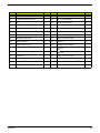
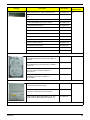
SX2380 FRU List
Category
Description
Part Number
Exploded
Diagram Item
MB Kit
MB kit gVic AMD A75 Realtek 8111F Acer Logo
DTX W/O 1394 LF w/ USB3.0
DB.GDE11.001
MB Kit SX2380 AMD A75 Realtek 8111FA Y W/O
1394 V1.0 LF DTX Win8
DB.GDS11.001
Hon Hai Chassis xSFF HX097K w/i GTW logo, w/i
front USB2.0 port x2, w/o front WiFi module
support for GTW bezel GX170
DC.13111.007
Hon Hai Chassis xSFF HX097L w/i GTW logo, w/i
front USB2.0 port x2, w/i front WiFi module support
for GTW bezel GX171
DC.13111.008
Hon Hai GTW GX170 USB2.0 port x2 bezel, w/i 5in-1 combo MCR, w/o front WiFi module support
for HX097K
DC.11911.00A
Hon Hai GTW GX171 USB2.0 port x2 bezel, w/i 5in-1 combo MCR, w/i front WiFi module support for
HX097L
DC.11911.00B
Non-PFC 220W (8.5L) EuP
PY.2200B.009
Non-PFC 220W (8.5L) EuP
PY.22009.009
FR 220W (8.5L) EuP 82+
PY.2200B.011
FR 220W (8.5L) EuP 82+
PY.22009.011
Non-PFC 220W (8.5L) EuP
PY.2200F.004
FR 220W (8.5L) EuP 82+
PY.2200F.006
CPU AMD A8 5500 FM2 3.2G 4M 65W A-1 Quad
Core
KC.AA802.550
CPU AMD A10 5700 FM2 3.4G 4M 65W A-1 Quad
Core
KC.A1002.570
CPU AMD A6 5400K FM2 3.6G 1M 65W A-1 Quad
Core
KC.KA602.540
CPU AMD A6 5300 FM2 3.6G 1M 65W A-1 Dual
Core
KC.AA402.530
3
Chassis
N/A
Bezel
N/A
Power Supply
9
CPU
N/A
Memory
98
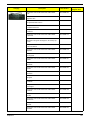
Chapter 6
Category
Description
Part Number
GU502203EP0201 LF 128*8 0.065um (1G bit)
KN.1GB0H.015
ACR128X64D3U1333C9 LF 128*8 0.07um (1G
bit)
KN.1GB07.002
RMR1810EF48E7W-1333 (1G bit)
KN.1GB0R.002
"NT1GC64BH4B0PF-CG (2G bit, 128x16)"
KN.1GB03.035
HU524303EP0200 (2G bit)
KN.2GB0H.012
NT2GC64B88G0NF-CG V79D (2G bit)
KN.2GB03.026
RMR1810EC58E8F-1333 (1G bit)
KN.2GB0R.002
AD63I1B0823EV (2G bit)
KN.2GB0C.009
ACR256X64D3U13C9G (2G bit)
KN.2GB07.007
NT4GC64B8HG0NF-CG (2G bit)
KN.4GB03.010
AD63I1C1624EV (2G bit)
KN.4GB0C.002
HU564403EP0200 (2G bit)
KN.4GB0H.001
ACR512X64D3U13C9G (2G bit)
KN.4GB07.002
MT16JTF51264AZ-1G4D1 4GB
KN.4GB04.002
HDD SEAGATE 3.5" 7200rpm 500GB
ST3500413AS(Pharaoh 6G) SATA III 16MB LF F/
W:JC45
KH.50001.022
HDD SEAGATE 3.5" 7200rpm 1000GB
ST31000524AS ( Pharaoh 6G) SATA III 32MB LF
F/W:JC45
KH.01K01.016
HDD WD 3.5" 7200rpm 500GB WD5000AAKX221CA1 XL500-1D SATA III 16MB LF F/
W:17.01H17
KH.50008.025
HDD WD 3.5" 5400rpm 1000GB WD10EARX22N0YB0 GP667 SATA III 64MB LF F/
W:51.0AB51
KH.01K08.020
ODD HLDS Super-Multi DRIVE HH 16X GH80N
LF+HF Black Bezel SATA (Win7)
KO.0160D.002
ODD PLDS Super-Multi DRIVE HH DL 16X DH16ACSH LF Black Bezel (HF+Win7) SATA
KU.0160F.013
ODD PIONEER Super-Multi DRIVE HH DL 16X
DVR-219RS LF Black Bezel SATA (Win7+HF)
KU.01605.007
Exploded
Diagram Item
N/A
HDD
4
ODD
7
VGA
Chapter 6
99
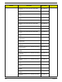
Category
Description
Part Number
Exploded
Diagram Item
288-5E181-X02AC HD7670 2GB DDR3 128bit
DVI-I + HDMI LP
VG.PCP76.702
N/A
288-5E181-X02A8 AMD HD7670 2GB DDR3
128bit UEFI DVI-I + HDMI LP
VG.PCU76.702
WN7601R, Ralink RT3090, 802.11b/g/n 1x1
WLAN PCI-E x1 card (Low-profile)
NI.10200.038
Lite-On WN6607LH WLAN WN6607LH, Realtek
RTL8191SU, 802.11bgn 1Tx2R WLAN (minicard)(USB interface) Half Size
NI.10200.041
D-1156E#/A10A (Low-profile), Modem PCI-Ex1
card, LSI Universal Modem (PCI-E) 56K V.92 Concorde (C40)
FX.10100.003
N/A
Neosonica speaker USB NEO 2003 with black
color
SP.10600.032
N/A
Neosonica speaker USB NEO 2003 with black
color; meet AJC spec
SP.10600.040
Logitech Optical mouse USB M-U0027-O with
polish cover
MS.11200.081
Primax Optical mouse USB MOFFUO with polish
cover
MS.11200.083
Lite-on P5 optical mouse RF2.4 SM-9661 with
receiver(nano dangle)
MS.11200.084
Lite-on P5 optical mouse RF2.4 SM-9661 with
receiver ; without battery
MS.11200.095
Keyboard LITE-ON SK-9020 USB 104KS Black
US
KB.USB0B.283
Wireless LAN Card
N/A
Modem
External Speaker
Mouse
N/A
Keyboard
100
N/A
Chapter 6
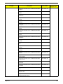
Category
Chapter 6
Description
Part Number
Keyboard LITE-ON SK-9020 USB 105KS Black
UK
KB.USB0B.284
Keyboard LITE-ON SK-9020 USB 105KS Black
Spanish Latin
KB.USB0B.285
Keyboard LITE-ON SK-9020 USB 105KS Black
English/Canadian French
KB.USB0B.286
Keyboard LITE-ON SK-9020 USB 104KS Black
Traditional Chinese
KB.USB0B.287
Keyboard LITE-ON SK-9020 USB 104KS Black
Thailand
KB.USB0B.373
Keyboard LITE-ON SK-9020 USB 109KS Black
Japanese
KB.USB0B.374
Keyboard LITE-ON SK-9020 USB 109KS Black
Brazilian Portuguese leverage the JA 109 key top
cover
KB.USB0B.375
Keyboard LITE-ON SK-9020 USB 105KS Black
US International
KB.USB0B.378
Keyboard LITE-ON SK-9020 USB 105KS Black
Spanish
KB.USB0B.379
Keyboard LITE-ON SK-9020 USB 105KS Black
Portuguese
KB.USB0B.380
Keyboard LITE-ON SK-9020 USB 105KS Black
Italian
KB.USB0B.381
Keyboard LITE-ON SK-9020 USB 105KS Black
Swedish
KB.USB0B.382
Keyboard LITE-ON SK-9020 USB 105KS Black
Dutch
KB.USB0B.383
Keyboard LITE-ON SK-9020 USB 105KS Black
Swiss/G
KB.USB0B.384
Keyboard LITE-ON SK-9020 USB 105KS Black
Belgium
KB.USB0B.385
Keyboard LITE-ON SK-9020 USB 105KS Black
Icelandic
KB.USB0B.386
Keyboard LITE-ON SK-9020 USB 105KS Black
Norwegian
KB.USB0B.387
Keyboard LITE-ON SK-9020 USB 105KS Black
Hebrew
KB.USB0B.388
Keyboard LITE-ON SK-9020 USB 105KS Black
Polish
KB.USB0B.389
Keyboard LITE-ON SK-9020 USB 105KS Black
Slovenian
KB.USB0B.390
Keyboard LITE-ON SK-9020 USB 105KS Black
Slovak
KB.USB0B.391
Keyboard LITE-ON SK-9020 USB 105KS Black
Russian
KB.USB0B.392
Exploded
Diagram Item
101
Category
102
Description
Part Number
Keyboard LITE-ON SK-9020 USB 105KS Black
Hungarian
KB.USB0B.393
Keyboard LITE-ON SK-9020 USB 105KS Black
Greek
KB.USB0B.394
Keyboard LITE-ON SK-9020 USB 105KS Black
Danish
KB.USB0B.395
Keyboard LITE-ON SK-9020 USB 105KS Black
Czech
KB.USB0B.396
Keyboard LITE-ON SK-9020 USB 105KS Black
Romanian
KB.USB0B.397
Keyboard LITE-ON SK-9020 USB 105KS Black
Turkish
KB.USB0B.398
Keyboard LITE-ON SK-9020 USB Black Turkish-Q
KB.USB0B.405
Keyboard LITE-ON SK-9020 USB 105KS Black
French
KB.USB0B.399
Keyboard LITE-ON SK-9020 USB 105KS Black
German
KB.USB0B.400
Keyboard LITE-ON SK-9020 USB 105KS Black
Nordic
KB.USB0B.401
Keyboard LITE-ON SK-9020 USB 105KS Black
Arabic/English
KB.USB0B.402
Keyboard LITE-ON SK-9020 USB 105KS Black
Arabic/French
KB.USB0B.403
Keyboard LITE-ON SK-9020 USB 105KS Black
Swiss/FR
KB.USB0B.404
Keyboard CHICONY KU-1112 USB Standard Black
US International
KB.USB03.330
Keyboard CHICONY KU-1112 USB Standard Black
Spanish
KB.USB03.331
Keyboard CHICONY KU-1112 USB Standard Black
Portuguese
KB.USB03.332
Keyboard CHICONY KU-1112 USB Standard Black
Italian
KB.USB03.333
Keyboard CHICONY KU-1112 USB Standard Black
Swedish
KB.USB03.334
Keyboard CHICONY KU-1112 USB Standard Black
Dutch
KB.USB03.335
Keyboard CHICONY KU-1112 USB Standard Black
Swiss/G
KB.USB03.336
Keyboard CHICONY KU-1112 USB Standard Black
Belgium
KB.USB03.337
Keyboard CHICONY KU-1112 USB Standard Black
Icelandic
KB.USB03.338
Keyboard CHICONY KU-1112 USB Standard Black
Norwegian
KB.USB03.339
Exploded
Diagram Item
Chapter 6
Category
Chapter 6
Description
Part Number
Keyboard CHICONY KU-1112 USB Standard Black
Hebrew
KB.USB03.340
Keyboard CHICONY KU-1112 USB Standard Black
Polish
KB.USB03.341
Keyboard CHICONY KU-1112 USB Standard Black
Slovenian
KB.USB03.342
Keyboard CHICONY KU-1112 USB Standard Black
Slovak
KB.USB03.343
Keyboard CHICONY KU-1112 USB Standard Black
Russian
KB.USB03.344
Keyboard CHICONY KU-1112 USB Standard Black
Hungarian
KB.USB03.345
Keyboard CHICONY KU-1112 USB Standard Black
Greek
KB.USB03.346
Keyboard CHICONY KU-1112 USB Standard Black
Danish
KB.USB03.347
Keyboard CHICONY KU-1112 USB Standard Black
Czech
KB.USB03.348
Keyboard CHICONY KU-1112 USB Standard Black
Romanian
KB.USB03.349
Keyboard CHICONY KU-1112 USB Standard Black
Turkish
KB.USB03.350
Keyboard CHICONY KU-1112 USB Standard Black
UK
KB.USB03.351
Keyboard CHICONY KU-1112 USB Standard Black
French
KB.USB03.352
Keyboard CHICONY KU-1112 USB Standard Black
German
KB.USB03.353
Keyboard CHICONY KU-1112 USB Standard Black
Nordic
KB.USB03.354
Keyboard CHICONY KU-1112 USB Standard Black
Arabic/English
KB.USB03.355
Keyboard CHICONY KU-1112 USB Standard Black
Arabic/French
KB.USB03.356
Keyboard CHICONY KU-1112 USB Standard Black
Swiss/FR
KB.USB03.357
Keyboard CHICONY KU-1112 USB Standard Black
Turkish-Q
KB.USB03.358
Keyboard CHICONY KU-1112 USB Standard Black
US
KB.USB03.359
Keyboard CHICONY KU-1112 USB Standard Black
Spanish Latin
KB.USB03.360
Keyboard CHICONY KU-1112 USB Standard Black
English/Canadian French
KB.USB03.361
Exploded
Diagram Item
103
Category
104
Description
Part Number
Keyboard CHICONY KU-1112 USB Standard Black
Traditional Chinese
KB.USB03.362
Keyboard CHICONY KU-1112 USB Standard Black
Thailand
KB.USB03.363
Keyboard CHICONY KU-1112 USB Standard Black
Japanese
KB.USB03.364
Keyboard CHICONY KU-1112 USB Standard Black
Brazilian Portuguese leverage the JA 109 key top
cover
KB.USB03.365
Keyboard LITE-ON SK-9061 RF2.4 104KS Black
US
KB.RF40B.083
Keyboard LITE-ON SK-9061 RF2.4 104KS Black
Traditional Chinese
KB.RF40B.084
Keyboard LITE-ON SK-9061 RF2.4 104KS Black
Thailand
KB.RF40B.085
Keyboard LITE-ON SK-9061 RF2.4 105KS Black
Spanish Latin
KB.RF40B.086
Keyboard LITE-ON SK-9061 RF2.4 Black Spanish
Latin without battery
KB.RF40B.122
Keyboard LITE-ON SK-9061 RF2.4 107KS Black
Brazilian Portuguese
KB.RF40B.087
Keyboard LITE-ON SK-9061 RF2.4 109KS Black
Japanese
KB.RF40B.088
Keyboard LITE-ON SK-9061 RF2.4 105KS Black
UK
KB.RF40B.089
Keyboard LITE-ON SK-9061 RF2.4 105KS Black
English/Canadian French
KB.RF40B.090
Keyboard LITE-ON SK-9061 RF2.4 105KS Black
US International
KB.RF40B.093
Keyboard LITE-ON SK-9061 RF2.4 105KS Black
Spanish
KB.RF40B.094
Keyboard LITE-ON SK-9061 RF2.4 105KS Black
Portuguese
KB.RF40B.095
Keyboard LITE-ON SK-9061 RF2.4 105KS Black
Italian
KB.RF40B.096
Keyboard LITE-ON SK-9061 RF2.4 105KS Black
Swedish
KB.RF40B.097
Keyboard LITE-ON SK-9061 RF2.4 105KS Black
Dutch
KB.RF40B.098
Keyboard LITE-ON SK-9061 RF2.4 105KS Black
Swiss/G
KB.RF40B.099
Keyboard LITE-ON SK-9061 RF2.4 105KS Black
Belgium
KB.RF40B.100
Keyboard LITE-ON SK-9061 RF2.4 105KS Black
Icelandic
KB.RF40B.101
Exploded
Diagram Item
Chapter 6
Category
Chapter 6
Description
Part Number
Keyboard LITE-ON SK-9061 RF2.4 105KS Black
Norwegian
KB.RF40B.102
Keyboard LITE-ON SK-9061 RF2.4 105KS Black
Hebrew
KB.RF40B.103
Keyboard LITE-ON SK-9061 RF2.4 105KS Black
Polish
KB.RF40B.104
Keyboard LITE-ON SK-9061 RF2.4 105KS Black
Slovenian
KB.RF40B.105
Keyboard LITE-ON SK-9061 RF2.4 105KS Black
Slovak
KB.RF40B.106
Keyboard LITE-ON SK-9061 RF2.4 105KS Black
Russian
KB.RF40B.107
Keyboard LITE-ON SK-9061 RF2.4 105KS Black
Hungarian
KB.RF40B.108
Keyboard LITE-ON SK-9061 RF2.4 105KS Black
Greek
KB.RF40B.109
Keyboard LITE-ON SK-9061 RF2.4 105KS Black
Danish
KB.RF40B.110
Keyboard LITE-ON SK-9061 RF2.4 105KS Black
Czech
KB.RF40B.111
Keyboard LITE-ON SK-9061 RF2.4 105KS Black
Romanian
KB.RF40B.112
Keyboard LITE-ON SK-9061 RF2.4 105KS Black
Turkish
KB.RF40B.113
Keyboard LITE-ON SK-9061 RF2.4 Black TurkishQ
KB.RF40B.123
Keyboard LITE-ON SK-9061 RF2.4 105KS Black
French
KB.RF40B.114
Keyboard LITE-ON SK-9061 RF2.4 105KS Black
German
KB.RF40B.115
Keyboard LITE-ON SK-9061 RF2.4 105KS Black
Nordic
KB.RF40B.116
Keyboard LITE-ON SK-9061 RF2.4 105KS Black
Arabic/English
KB.RF40B.117
Keyboard LITE-ON SK-9061 RF2.4 105KS Black
Arabic/French
KB.RF40B.118
Keyboard LITE-ON SK-9061 RF2.4 105KS Black
Swiss/FR
KB.RF40B.119
Exploded
Diagram Item
105