1
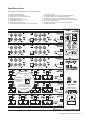
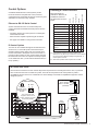
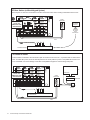
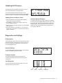
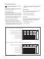
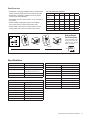
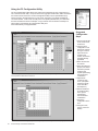
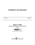
Installation and Operation
Component Video/Audio Source Inputs
Dual Cat 5 Outputs to Zone Receivers
WARNING:
AVERTISSEMENT:
100-125V~ 50-60 Hz
Pour réduire les risques d’incendie ou de choc
To reduce the risk of fire or electric shock,
Replace do
Fuse Only with
not expose this apparatus to rain or moisture.
T 2.5A, 250Vac électrique, ne pas exposer cet appareil à la pluie ni à
The lightning flash within an equilateral
triangle is intended to alert the user to
the presence of uninsulated “dangerous
voltage” within the product’s enclosure
that may be of sufficient magnitude
to constitute a risk of electric shock to
persons.
l’humidité.
Remplacer Uniquement
avec Fuse T 2.5A, 250Vac
L’éclair terminé d’une flèche à l’intérieur d’un
triangle indique à l’utilisateur la présence à
l’intérieur de l’appareil d’une tension dangereuse
non isolée ayant une amplitude suffisante pour
provoquer une électrocution.
The exclamation point within an equilateral triangle is intended
to alert the user to the presence of important operating
and maintenance (servicing) instructions in the literature
accompanying the appliance.
The exclamation point symbol within the eight-sided shape
alerts users to important operating and maintenance instructions
in this booklet.
Le point d’exclamation à l’intérieur d’un triangle indique que
des instructions de fonctionnement et d’entretien importantes
sont detaillées dans les documents fournis avec l’appareil.
!
Le point d’exclamation à l’intérieur de l’octagone indique à
l’utilisateur que des importantes instructions d’opération et
d’entretien sont incluses dans ce document.
• Read these instructions.
• Lire toutes les directives avant de mettre l’appareil en opération.
• Keep these instructions.
• Conserver les directives de sécurité and d’utilisation pour future
consultation.
• Heed all warnings.
• Follow all instructions.
• This product must be installed by qualified personnel.
• Do not open the cover—there are no user-serviceable
parts inside.
• Do not use this apparatus near water.
• Clean only with dry cloth.
• Do not block any ventilation openings. Install in
accordance with the manufacturer’s instructions.
• Do not install near any heat sources such as radiators,
heat registers, stoves, or other apparatus (including
amplifiers) that produce heat.
• Do not defeat the safety purpose of the grouding-type
plug. If the provided plug does not fit into an outlet, consult
an electrician for replacement of the obsolete outlet.
• The power cord is used as a disconnect device; it shall
remain readily operable. Do not prevent cord from being
unplugged from apparatus.
• Protect the power cord from being walked on or pinched,
particularly at plugs, convenience receptacles, and the
point where it exits from the apparatus.
• Use only attachments/accessories specified by the
manufacturer.
• Unplug this apparatus during lightning storms or when
unused for long periods of time.
• Refer all servicing to qualified service personnel. Servicing
is required when the apparatus has been damaged in any
way, such as power-supply cord or plug is damaged, liquid
has been spilled or objects have fallen into the apparatus,
the apparatus has been exposed to rain or moisture, does
not operate normally, or has been dropped.
• Tenir compte des avertissements.
• Suivre les directives.
• Ce produit doit être installé par un personnel qualifié.
• Afin d’éviter tout risque d’électrocution, ne pas retirer le capot
ou la couvercle. Aucune des pieces intérieures n’est réparable
par l’utilisateur. Pour toute réparation, s’adresser à un technician
d’entretien qualifié.
• Ne pas utiliser cet appareil près de l’eau.
• Nettoyer seulement avec un chiffon sec.
• Les ouvertures et fentes dans le chassis sont prevues pour la
ventilations de l’appareil. Ces ouvertures ne doivent pas être
bloquées. Installer conformement aux directives du manufacturier.
• L’appareil doit être situé loin de sources de chaleur telles que des
radiateurs, des registres de chaleur, des forneaux, ou d’autres
appareils produisant de la chaleur.
• Ne pas modifier le dispositif de securité de la fiche ayant une broche
de mise à la terre. S’il est impossible d’insérer la fiche dans la prise
de courant, contacter un électricien pour remplacer la prise de
courant.
• Le cordon d’alimentation est utilisé comme un dispositif de
déconnexion; Il doit rester aisément fonctionnel. Ne pas prevenir le
cordon d’alimentation de démonter de l’appareil.
• Les cordons d’alimentation devraient être disposés de façon à ce
qu’on ne puisse pas marcher dessus ou qu’ils soient susceptibles
d’etre coincés par des articles placés sur ou contre eux. Une
attention particulière doit etre portée aux fiches, prises de courant,
et aux points où ils sortent de l’appareil.
• Utiliser seulement les attachements et accessoires recommendés
par le manufacturier.
• Débrancher l’appareil de la prise d’alimentation pendant un orage
électrique ou une absence d’utilisation prolongée.
• Confier tout entretien à un personnel de service qualifié.
• Un service d’entretien est necéssaire quand l’appareil ne fonctionne
pas normalement en suivant les consignes d’utilisation, quand
le cordon d’alimentation ou sa fiche sont endommagés, quand
des objets sont tombés dans l’appareil, quand du liquide y a étè
renversé, ou quand l’appareil a étè exposé à la pluie ou à l’eau.
2
Audio Authority HLX Series User Manual
Installation and Operation Manual
This document is consistent with HLX configurations that include Model 2114 and 2248 cards, with features in firmware
version 1.0
Contents
Warnings . . . . . . . . . . . . . . . . . . . . . . . . . . . . . . . . . . . . . . . . . . . . . . . 2
The HLX Product Family . . . . . . . . . . . . . . . . . . . . . . . . . . . . . . . . . . . 4
Installation . . . . . . . . . . . . . . . . . . . . . . . . . . . . . . . . . . . . . . . . . . . . . . . 7
Control Options and Setup . . . . . . . . . . . . . . . . . . . . . . . . . . . . . . . . . . 9
Operation . . . . . . . . . . . . . . . . . . . . . . . . . . . . . . . . . . . . . . . . . . . . . . . . 11
Serial and Ethernet Control Setup . . . . . . . . . . . . . . . . . . . . . . . . . . . . 13
Troubleshooting Guide . . . . . . . . . . . . . . . . . . . . . . . . . . . . . . . . . . . . 14
Updating Firmware . . . . . . . . . . . . . . . . . . . . . . . . . . . . . . . . . . . . . . . 15
Diagnostic Modes . . . . . . . . . . . . . . . . . . . . . . . . . . . . . . . . . . . . . . . . 15
How to Configure HLX Systems . . . . . . . . . . . . . . . . . . . . . . . . . . . . . 16
Specifications . . . . . . . . . . . . . . . . . . . . . . . . . . . . . . . . . . . . . . . . . . . 17
Serial and Ethernet Commands . . . . . . . . . . . . . . . . . . . . . . . . . . . . . 19
Using the PC Configuration Utility . . . . . . . . . . . . . . . . . . . . . . . . . . . . 21
Warranty Statement . . . . . . . . . . . . . . . . . . . . . . . . . . . . . . . . . . . . . . . 23
Audio Authority and the Double-A Symbol are registered trademarks of Audio Authority Corp. Copyright February, 2011, all rights reserved.
Lexington, Kentucky
www.audioauthority.com
800-322-8346
Audio Authority HLX Series User Manual
3
Introducing HLX
The HLX Series of modular matrix systems is designed to
be easy to control, expand, and customize for a wide range
of audio/video applications. It features multiple control
interfaces, a flexible number of video and audio inputs/
outputs, and an ultra-wide bandwidth bus which enables
large matrix systems with no loss in signal quality. The
HLX Series offers IR, RS-232 and Ethernet control. Dual
Cat 5 output cards feature pathways for IR control signals
originating in the zones.
Benefits for the Installer
General HLX Features
• Optimize picture quality at each zone location with our
Exclusive Active Gain Equalization (AGE) technology
• From 4 to 12 audio/video sources
• From 8 to 32 A/V zone outputs (depending on sources)
• Compatible with Ethernet, RS-232 serial, front panel IR,
rear panel IR control signal input
• Durable, easy to clean touch-sensitive front panel
• Supports component video, analog audio, digital audio
and IR
• Supports HD video resolutions up to 1080p*
• Cross-converts** digital audio – digital coax and
optical inputs are converted and output in both formats
simultaneously
• Breakaway switching allows selecting audio and video
sources independently
• Modular card cage design for maximum flexibility
• Heavy duty, rack mountable, all metal construction
• Designed and built in Lexington, KY, USA
• Permanent viewing restrictions on any number of zone/
source combinations
• Locking front panel controls can prevent tampering
• Delivers component video up to 1080p*, digital and
analog audio*** to zone receivers over Cat 5e/6 cables
• Cat 5 bus includes power for the zone receiver and an IR
pathway for control signals from each zone***
• Five different Cat 5 receiver styles are available***
• LAN control via telnet using commands
• IR codes available for use with control systems including
Control 4, Logitech Harmony, and URC.
• Unique IR signal routing allows discrete control of
multiple sources of the same brand from different zones
• Efficient setup via downloadable PC application
• Requires no external power supply
Benefits for the User
• Compatible with most control interface systems
• Any viewer can restrict other zones from viewing and/or
controlling his or her source (expires after 5 hours)
• Content in each zone can be monitored and controlled
from the HLX panel interface
* Many sources do not support 1080p output on component video; they may offer 1080p only on copy protected,
digital video outputs. Similarly, some TVs are not capable of displaying 1080p, even if they accept 1080p signals.
!
** Digital audio inputs are not converted to analog outputs, or vice versa.
*** Analog audio and IR pathways are only available using 2248 zone cards with dual Cat 5 receivers. IR must be
wired separately when used in a Single Cat 5 receiver zone (see page 18 for details).
4
Audio Authority HLX Series User Manual
Panel Descriptions
Shown below is a Model 2006 card cage at full capacity.
A
B
C
D
E
F
G
H
Ethernet communication port
RS-232 serial communication port
IR input via 3.5mm for controlling HLX only
AC power port and fuse
Optical digital audio input (Source 4)
Coaxial digital audio input
Left and right analog audio input
Component video YPbPr (do not use for composite video)
I
J
K
L
M
N
O
P
F
IR output for Source 4
Source card status light (green) and IR activity light (yellow)
12 V power switches for IR pathways (see page 12)
IR input jack for sending IR commands to the HLX and sources
IR output jack for sending or receiving zone IR via the Cat 5 pathway
Zone 8 Cat 5 outputs A and B
Zone card status light (green) and IR activity light (yellow)
Chassis serial number
G
H
E
A
I
J
B
C
About
IR Power Switches
IN
CAUTION
Improper use can
cause equipment
damage!
OUT
K
Turn on IR power when
equipment, such as an IR
receiver, requires 12V power
via the Cat 5 pathway.
See page 12.
100-125V~
50-60
Hz Hz
2.2A
100-125V~
50-60
Replace Fuse Only with
T 2.5A, 250Vac
Remplacer Uniquement
avec Fuse T 2.5A, 250Vac
K
L
M
N
O
D
P
Audio Authority HLX Series User Manual
5
A
HLX System Design
The basic HLX Series components covered in this manual
include the Model 2006 card cage, AV source cards and
AV zone cards, as described below. For information about
expansion card cage, and other source and zone cards,
refer to the item’s separate manual.
Cat 5 zone cards require Audio Authority zone receivers.
Three Dual Cat 5 styles are available, and two single Cat 5
styles. See page 18 for complete information about zone
receiver features.
B
9880
9878
9879
Card Cage Features
The front panel includes the display, IR receiver, keys and
knob, plus a USB port. The rear panel includes six slots for
signal switching cards, a specially designed, robust internal
power supply. The power supply module also provides the
location for the control interface connections.
C
Matrix Switching Cards
Note: other types of source and zone cards are in
development; visit www.audioauthority.com for details.
• 2114 Source Cards – component video, stereo analog
audio, digital coaxial audio, digital optical audio, and IR
out jacks. Four sources per card.
• 2248 Zone Cards – Dual Cat 5 outputs for zone
receivers carrying component video, stereo analog
audio, digital coaxial audio, digital optical audio, and
IR signals. IR injection jacks for incoming and outgoing
control signals. Eight zones per card.
D
• 2100 Blank Panel – Covers unused card slots.
Example Configurations
Configurations including 12x24 (A), 8x32 (B), 12x16
(C), and 8x16 (D), and 12x8 (E) are shown at the right.
Example B represents the maximum number of zones
using the Model 2006 card cage. Example A (Model
HLX-12C-24D) and example D (Model HLX-8C-16D) are
standard configurations available for purchase at
www.audioauthority.com. Call Audio Authority for details
on other configurations, and visit www.audioauthority.com
to learn about new cards and card cages as HLX Series
development proceeds.
6
Audio Authority HLX Series User Manual
E
Installation
1.Read this entire instruction manual.
Other Items Required for Installation
2.Confirm that nothing is missing from your shipping carton
(see below).
• Audio Authority Cat 5 Zone Receivers
3.Activate your warranty and receive future update
notifications by registering your purchase on our website:
www.audioauthority.com/register.
• Professional Category 5e/6 cable tester*
4.Write the serial number (see product rear panel) inside
the back cover of this manual.
5.Connect associated equipment (sources, TVs, etc.)
6.Connect the HLX to a suitable power outlet and test.
7.Perform desired setup operations via RS-232 or Ethernet
if desired (see Appendix A).
Carton Contents
1.Model 2006 card cage with installed cards
• Cat 5e/6 UTP cable
• Patch cables (Ethernet, RCA, and/or optical)
• Coaxial cable and RCA terminations for zone outputs
• Infrared receivers
Suggested Accessories
• Model 1360 Down-converter: converts component video
to composite or S-Video for legacy TVs.
• Model 1362 Up-converter/scaler: converts composite
or S-video signals to component video for legacy video
sources.
• Model 1366 Video Converter: converts YPbPr to RGBHV
or VGA to YPbPr for incompatible video sources or
projectors and video displays.
2.Power cord
3.User manual
Example System 1
SOURCE 1
In this 12x24 Dual Cat 5 HLX configuration, the installer
uses the Cat 5 pathway to send IR signals from the zone
to the sources. See page 9 for alternative IR connection
options.
DIGITAL AUDIO
ANALOG AUDIO
COMPONENT VIDEO
ZONE IR SIGNALS
IN
In each video zone the installer can choose to use stereo
audio for TV sound and/or digital audio for surround sound
via a home theater receiver.
OUT
TV
VIDEO
CAUTION
Improper use can
cause equipment
damage!
TV AUDIO
DIGITAL AUDIO
CAT 5E/6 CABLES
9879
CAT 5 RECEIVER
HOME THEATER
RECEIVER
IR RECEIVER
* It is strongly recommended to test both factory made and site fabricated cables with a professional tester; balanced line pairing order is
crucial for optimal picture quality. Continuity testing of the cable lines does not insure noise free performance.
Audio Authority HLX Series User Manual
7
Hardware Installation
The HLX system is designed to be mounted in a standard
19-inch equipment rack. Secure the card cage to the rails
with all four screws (supplied). If your system includes
an expansion card cage (Model 2014) install it first, then
carefully seat the main HLX card cage onto the multi-pin
connector and fasten it to the rack. Check that each preinstalled card is properly seated and secured in the card
cage.
!
B
Source Card IR Outputs
IR outputs on source cards relay IR data from the zones to
the source device. Connect IR emitters or blasters from the
IR output jacks on each source card to each source device.
Place the blaster directly over the IR receiver on the front
panel, or, if available, connect a patch cord to the IR input
on the rear panel.
Model
9879
Source
Card
Connect to
Source IR
receiver.
Terminating Cat 5e and Cat 6
1.Install RJ-45 plugs using EIA-568B pairing (pins
1-2, 3-6, 4-5, 7-8).
2.Check each cable with a professional network
cable tester before plugging it into the zone card,
even when using pre-made cables. Continuity
testing is not adequate! The twisted pairs must be
properly matched for balanced line transmission.
Wiring Dual Cat 5 Zones
• Zone Card – Model 2248 Carefully mark two Cat 5e/6
cables as cable A and B and pull them to the receiver
location. It is imperative that the A and B cables are
correctly connected to the zone receiver and the zone
card; swapping cables can result in permanent damage
to the receiver.
• Zone Receiver – Model 9879 Carefully connect the
cables marked A and B to the appropriate Cat 5 jacks
on the zone receiver. Set the cable length compensation
rotary switch based on the length of the cables (0 for
0-99 feet, 1 for 100-199 feet, etc). Connect high quality
component video, analog audio, and digital coaxial
audio cables to the zone receiver. Finally, connect an IR
receiver to the front or back of the zone receiver.
• IR Input and Output jacks – The two 3.5mm jacks for
each zone card output are used for special control
signals. The IN jack sends signals to the HLX and to
sources via the source card IR jacks. The OUT jack
sends OR recieves signals via the Cat 5 zone pathway.
• Zone IR 12V Power – Do not turn on (down position) the
12V switch unless compatible equipment requires 12V
power. See the example diagram on page 12 for details.
Pair 3
Pair 2
Audio Authority HLX Series User Manual
Pair 1
Pair 4
Modular Jack (RJ-45)
1 2 3 4 5 6 7 8
W-O O W-GR BL W-BL GR W-BR BR
T568B Pair Assignments
Dual Cat 5 Zone
Card IR Switches
Enable 12V for a
zone that includes a
compatible IR receiver.
CAUTION
Improper use can
cause equipment
damage!
8
CAUTION!
Do not apply system
power until cables
are tested and A and
B connections have
been verified.
Wiring Sources and Initial Testing
Component Video Source Card – Model 2114
Connect high quality component video cables (YPbPr),
analog audio (L/R) and either digital coaxial audio or digital
optical audio (one form of digital audio ONLY) to each
source input. If both analog and digital audio signals are
desired in a zone, both digital AND anlalog audio inputs
must be connected from the source to the HLX source
card.
A
12V SWITCHES
IN
OUT
Control Options
Choosing a Control Interface
Ethernet
Front Panel IR
Zone IR
Panel Controls
Most commands are
available on Ethernet, IR
and RS-232, but there
are differences as shown
below.
RS-232
Centralized serial Ethernet control systems provide
the most robust and complete HLX control, however,
comprehensive IR controllers and zone IR control are good
alternatives for most day to day activities.
A/V signal switching
✔
✔
✔
✔
✔
Favorites switching
✔
✔
✔
✔
✔
Groups switching
✔
✔
✔
✔
✔
Dimming
✔
✔
✔
-
✔
Breakaway switching
✔
✔
✔
✔
-
• Serial control is capable of performing all commands
Lockout (restrict)
✔
✔
✔
✔
-
• See page 19 for details on using serial commands
Disable front panel IR
✔
✔
✔
-
✔
Lock IR
✔
✔
-
-
✔
Lock front panel keys
✔
✔
-
-
✔
Change Ethernet
settings
✔
(a)
-
-
-
Update firmware (b)
-
-
-
-
✔
Ethernet or RS-232 Serial Control
System controllers and PCs can send all setup and
control commands via the RS-232 serial port and receive
feedback.
• Important: observe the correct pinout for controlling the
HLX via RS-232 cable
IR Control Options
The HLX can be controlled through IR commands issued
at each zone, or via the IR inputs at the head end (see
example systems below). Either use an IR remote with a
receiver connected to the IR jack on the zone receiver, or
program an RF controller or other control system with HLX
IR commands and connect its outputs to the IR input jacks
on the 2248 zone card. (12 volt switches should be OFF, in
the up position.)
(a) If an automatic IP protocol is used to obtain an IP
address, the only direct way to obtain the new IP address
is to query the HLX Ethernet settings using RS-232, or
use front panel controls.
(b) All firmware updates must be performed via USB.
IR Control from Zones
An IR receiver connected to a zone receiver IR jack can be powered via connecting block in the zone, or powered
with 12 volts from the HLX. To enable HLX power, move the OUT dip switch to the down position to power a
compatible IR receiver in the zone. CAUTION: Can cause damage if used with incompatible IR equipment. Check
voltage and pinout.
Tip = Signal
Ring = Ground
Sleeve = +12 Volts
(If enabled)
IR Power Switches
IN
OUT
CAUTION
Improper use can
cause equipment
damage!
Turn on IR power when
equipment, such as an IR
receiver, requires 12V power
via the Cat 5 pathway.
IR RECEIVER
ZONE
RECEIVER
CAT 5
IR
REMOTE
Audio Authority HLX Series User Manual
9
RF Base Station (or Wired Keypad System)
The IR IN jack on HLX zone cards allows controllers at the head end to mimic sending commands from the zones.
DO NOT TURN
ON IR +12V
SWITCH IN THIS
APPLICATION
IR IN
ZONE
RECEIVER
IR OUT
OFF
RF Remote
for Zone 1
+12V
1
A
B
RF signals
sent to
Base Station
CAT 5
ZONE 1 IR OUTPUT
1 2 3 4 5 6
RF BASE STATION
IR Control to Zones
An IR controller connected to the HLX IR OUT jack can send IR to the zone. The , or powered with 12 volts from the
HLX. To enable HLX power, move the OUT dip switch to the down position to power a compatible IR receiver in the
zone. CAUTION: Can cause damage if used with incompatible IR equipment. Check voltage and pinout.
TV
IR EMITTER
DO NOT TURN
ON IR +12V
SWITCH IN THIS
APPLICATION
ZONE
RECEIVER
IR EMITTER
RECEIVER
CONNECTING
BLOCK
1 2 3 4 5 6
IR CONTROLLER
CAT 5
10
Audio Authority HLX Series User Manual
Comprehensive IR Control System
The HLX can be used right out of the box; no setup is
necessary. Comprehensive IR controllers can use the
complete HLX IR code set, along with the codes of the
sources. HLX volume controls are not included in this code
1. Patch the IR signal directly to the IR input port on the
rear panel using a standard 3.5mm cable or, place a
stick-on emitter or blaster from the infrared system on
the HLX front panel optical IR receiver.
Logitech Harmony remote controls can access
the HLX IR codes in the Harmony database here:
Amplifier>Audio/Video Switch>Audio Authority>HLX.
Zone IR Control
1. Set up a programmable remote (URC, RTI, Logitech,
etc.) with HLX remote control codes.
2. If the HLX IR codes are available from your remote
control company, download and/or activate those files.
2. Connect an IR receiver to the HLX system either by
running the IR receiver cable directly to the input of a
2248 Zone Card, or connect the IR receiver to the zone
receiver IR jack.
3. A HEX file can be downloaded from the Audio Authority
website: www.audioauthority.com/page/software.
3. For operation tips, see the zone IR explanation in the
operation section below.
Operation
HLX Front Panel Controls
Front panel control is peformed via touch sensitive keys
and a selector knob.
• The default screen is the zone/source switching screen.
Scroll zones using the knob, press the knob to choose a
zone, then scroll and select a source.
• To perform multiple switching operations, use GROUP,
FAVORITE and ALL keys (some setup required).
• Touch MENU to access settings and scroll to a desired
item and press the knob to enter.
• Digits: the 0-9 digits on the remote can be used to enter
group or favorite numbers.
• Favorites: activates a predetermined combination of
zone/source selections; requires a number to be entered
on the 0-9 digits (1-10) before pressing the favorite
button for activation.
• Groups: sets a predetermined list of zones to the
specified source video, audio or both. This command
requires one to press the desired group number, group
button, audio or video modifiers, and finally the source
button.
• Press the BACK key to exit.
IR Operation Example
Zone IR Operation
HLX “Buttons” for Remote Control Systems
When programming a remote control system, the following
functions are available for operational controls:
• Source Buttons: 12 discrete buttons cause the source
connected to the zone to be switched, given the current
configuration (sources that do not exist or that are
restricted in some way cannot be selected).
• Audio/Video Buttons: breakaway switching is possible
by first pressing the audio or video button and then a
discrete source button; only the audio or video signal is
switched.
• Lock Access: remove other zones viewing the source
selected and temporarily restrict other zones from
selecting the source.
• Lock Control: temporarily restrict other zones from
passing IR to the selected source device.
• Unlock: cancel all temporary restrictions placed by the
activating zone.
Current Configuration:
• 8 source inputs (1-8)
• 8 zone outputs (1-8) on a Model 2248 output card
• No restrictions in place
• IR receiver connected to the HLX zone 1 IR input
• Favorite 7 is defined as: “zones 1-8 switch to source 2”
• Group 1 contains zones 1-4
Example Sequence of Commands
1. [SOURCE1] – zone 1 is connected to source 1
2. [VIDEO][SOURCE2] – switch zone 1 to view source 2
but remain listening to source 1
3. [LOCK ACCESS] – temporarily restrict zones 2-8 from
viewing source 2, the currently viewed source in zone
1. Breakaway is canceled for zone 1 and zone 1 is
forced to view and listen to source 2, the source that it
was viewing when the restriction was activated.
Audio Authority HLX Series User Manual
11
4. [SOURCE1] – switch zone 1 back to watching/listening
to source 1. The temporary restriction is canceled by
switching away from the restricted source.
5. [LOCK CONTROL] – temporarily restrict zones 2-8
from passing IR control to source 1. For example,
source 1 may be connected to a DVD player. Zones
2-8 would be unable to use DVD player IR remote
commands to enter commands such as stop, pause,
skip, etc.
6. [UNLOCK] – removes the temporary restriction of
controlling source 1.
7. [VOLUME UP] – has no effect on output cards that do
not have physical analog outputs; adjusts the volume
on an output card that has physical analog audio
outputs
8. [ 7 ][FAVORITE] – all zones 1-8 switch to source 2
Using Restrictions
The HLX system can be set up to deny certain
zones access to certain sources. These “restrictions”
can be either permanent (until reprogrammed) or
temporary (active until they are cancelled or expire).
Temporary Source Restrictions
This feature allows a viewer in one zone to view*
content privately; no other zone is able to view the
source while the temporary restriction is in place.
When activated, this restriction removes other zones
currently viewing the source. Temporary restrictions
automatically expire after five hours; alternatively
they are canceled by switching away from the
restricted source or explicitly issuing an unlock
command.
When a zone is removed from a newly restricted
source, it is automatically switched to the next
available source.
Example of Temporary Restriction
9. [ 1 ][GROUP][VIDEO][SOURCE4] – zones 1-4 are
switched to watching source 4 video, but remain
listening to the audio connected to the previous
selection (source 2)
• Zone 1 and zone 2 are viewing source 7.
• Zone 2 applies a temporary viewing restriction to
source 7.
• Zone 1 is switched to source 8 (presuming there is
no restriction in place that will prevent that action).
If there is a restriction in place that prevents
switching to a zone, the next zone is attempted.
If a zone only has access to a single source,
and that source becomes restricted, the zone
deactivates (black screen).
Placing and cancelling temporary restrictions have
other limitations based on the control interface and
will be described in their respective sections.
Temporary Control Restrictions (IR)
A Control Restriction prevents other zones from
controlling* the selected source through the HLX
integrated IR control pathway. Other zones may still
view the source. Temporary restrictions expire after
five hours, or by switching away from the restricted
source or issuing an unlock command.
Permanent Source Restrictions
When a zone is permanently restricted from viewing
a source, it may not select or view that source under
any circumstances. Temporary source restrictions
supplement permanent restrictions, and may add
further restrictions to the available sources that a
zone may access. Permanent source restrictions
can be applied or removed only through serial
or Ethernet commands, or by using the HLX
configuration utility on a PC.
* “View,” In the context of restrictions, means to select,
watch and/or listen to a given source. The term “control”
means to send IR commands through the HLX IR pathway
to control a source (e.g. change channels, stop, play, etc.).
12
Audio Authority HLX Series User Manual
Serial and Ethernet Control Setup
Serial Control
Serial commands can be used at any time via RS-232 or
Ethernet to change the HLX settings. See page 19 for a
complete list of commands.
Default RS-232 Port Settings
Transfer Rate
Data Bits
Stop Bits
Parity
Flow Control or Data Flow
Character type
Interface connector
DB-9 Electrical rating
DB-9 Pin-out
9600 bps
8
1
None
None
ASCII
DB-9
Pins 2 and 3, ±15 VDC
Pin 2, Tx
Pin 3, Rx
Pin 5, Ground
Shell, Ground
• All serial commands require opening and closing
brackets “[ ]” but do not require any periods, spaces, or
commas.
• Commands can be in any order: [RPZ1] = [R, Z1, P]
• Enter a line feed and carriage return after each
command.
• ASCII codes not specified are ignored (i.e. control codes,
unused alphanumeric characters, etc.).
Setup for Ethernet Control
Consult your network administrator if you are unfamiliar
with setting up a network connection.
HLX commands (see page 19 for a complete list) can
be issued using an Ethernet connection and a telnet
program. There are two LED indicators located next to the
Ethernet port N on the rear panel that will help in identifying
connection issues:
• Link - The Link LED is steadily lit if a connection is
detected and flashes when activity is present.
• Speed - The Speed LED is off for 10 base T, and on for
100 base T.
Using the Ethernet Port
the Ethernet port on the HLX. Connect a PC directly to
the Ethernet port using a crossover cable, or alternatively
use a standard Ethernet hub or switch and standard patch
cables. Once connected to a PC or network, by default the
HLX attempts to obtain an IP address automatically using
DHCP. To use static settings, see below.
Using DHCP
DHCP is enabled on the HLX by default. If DHCP is
enabled on your network, simply connect the HLX to
the network with an existing DHCP server to obtain all
necessary settings.
Static Addressing (Connected to a PC)
• The HLX must be given an IP address which will not
conflict with the PC. Go to the network settings (which
are found in control panel -> network -> local connection
properties of a PC running Windows XP).
• Change the TCP/IP protocol properties, and set the
IP address, gateway, and subnet mask, if they are
not already set. This can be arbitrarily done on a
direct connection, but a good choice for the settings
would be IP address of 192.168.0.1, subnet mask of
255.255.255.0, and an empty default gateway. Once
these values have been set, use serial commands to set
the network settings of the HLX in a similar manner, but
use a different IP address than that of the computer (for
example, 192.168.0.2).
Static Addressing (Through a Network)
• The HLX must be set to the same settings as the PC
except for the IP address, which must be one available
on the network. To determine this in Windows, use the
DOS prompt (Start->Run->cmd) commands ipconfig
and ping. Ipconfig will list the PC’s settings, and ping will
allow you to test addresses to make sure that nothing
else on the network has that address.
• Once connectivity is established, a telnet program such
as Hyper Terminal, Teraterm, PuTTY etc, must be used
to connect to the device. Enter the IP address of the
HLX and leave the default port (23) to connect. Once
connected, standard serial commands (listed in Appendix
A) can be issued in an identical manner to serial control.
Use a telnet client or terminal
program on a Mac or PC to send
and receive commands through
Audio Authority HLX Series User Manual
13
Troubleshooting
IR Interference
Rail Voltage Failure (four blinks)
There are many sources of possible IR interference
including LCD/Plasma screens, fluorescent lights, or space
heaters. IR receivers are unable to operate properly in the
presence of significant interference.
The card has determined that the voltage powering the
card is insufficient for proper operation.
1.Eliminate source of interference and use Plasma-proof
and/or LCD-proof IR receivers
1.Power off the system.
All cards in one cage Rail Voltage Failure
2.Experiment with relocating the IR receiver
2.Make sure an AC power cord is connected to the card
cage.
3.Check for IR interference using the IR diagnostics
3.Power on the system.
4.If the problem persists, contact support.
IR Compatibility
The HLX only works with 12 volt, three-wire receivers
(example, Xantech 291 Series).
IR Connectivity Problems
1.Use a professional cable tester and re-terminate bad
cable ends using EIA-568B color code.
2.IR receivers require power and may receive it from a
connecting block or from a Zone card itself depending on
the configuration. Contact support.
Note: native HLX IR commands sent from zone IR ports
are not passed to any of the HLX IR output jacks.
Does not repeat commands from a certain IR remote
• Some IR remotes cannot be processed by the HLX.
• IR output not properly connected to external IR system –
call Audio Authority Technical Support.
Does not respond to RS-232
• HLX commands not properly stored or programmed in
remote control system.
• Wrong type of RS-232 cable – See specifications for
proper cable pin-out on page 13.
1.Remove power from the system.
2.Disconnect all cables from the card.
3.Confirm that power is connected correctly to the cage in
which the card is installed.
4.Apply power to the system.
5.If the error is gone, it may be possible that a connected
device is drawing too much power due to some kind of
failure. If the error is still present, contact support.
6.Remove power from the system.
7.Connect one set of cables (for instance, one pair of dual
Cat 5 cables).
8.Confirm proper operation; repeat until the problem
component is found.
Flash Memory Error (five blinks)
There is a problem reading or writing to the flash memory
present on the card. Contact Technical Support.
No Video or Audio
Cat 5 Connected Zone
• Incorrect settings in software – See page 13.
1.Confirm that the Cat 5 cables used in the system have
been tested with a cable tester and re-terminate using
EIA-568B color code.
No Video or IR control after adding cage expander
2.Damaged Cat 5 port – try moving Cat 5 cables to a
different port to localize the problem.
• Incompatible firmware versions – update to latest
firmware (see www.audioauthority.com).
3.Damaged Cat 5 receiver – swap with a known good
receiver and connect to a known good output card port.
• Improperly seated connector – check connection for bent
pins and re-seat.
Component Connected Zone
Blinking Status Light on Source/Zone Card
When an unrecoverable condition has occurred on a
particular card, it flashes an indicator code consisting of a
set of pulses and then a short delay.
Three Blinks = Video Type Error
Four Blinks = Rail Voltage Failure
Five Blinks = Flash Memory Error
14
Single Card Rail Voltage Failure
Audio Authority HLX Series User Manual
1.Check that the cables are properly connected (Y =
green, Pb = blue, Pr = red) and that only one digital
audio connection (either coaxial or optical) is connected
to a source card.
2.Damaged port – try moving the cables to another port
and check operation.
Updating HLX Firmware
The latest firmware is available to download to your PC
from www.audioauthority.com/page/software.
Two separate update processes are used for HLX
firmware: Card Update and System update. These updates
are performed from one firmware file (FILENAME.SMM).
Updating Zone and Source Cards
1.Place the USB drive containing the latest operating
system data into the HLX USB port.
2.Touch MENU. The setup menu appears. Scroll and
choose “Update Firmware”.
3.Scroll to the latest operating system (e.g. 052710.SMM).
Press the knob.
4.The screen displays “Downloading…” for two or three
minutes, then “Completed”. Cycle power and the HLX is
ready for operation.
Updating System Firmware
To update system firmware, insert a USB drive containing
the firmware file (FILENAME.SMM) and cycle power. Click
the knob as soon as the LCD screen lights up. Select the
firmware update. The firmware takes several moments to
update. Do not interrupt this process by cycling power or
removing the USB drive.
Diagnostics and Settings
IR Diagnostics
The IR diagnostic report contains timing information about
detected IR signals. The IR diagnostic report can be sent
to a PC via serial port or Ethernet, or can be saved to a
connected USB flash drive.
Network Settings
This diagnostic displays Ethernet settings. These settings
are also accessible via serial commands.
Firmware Versions
This diagnostic displays the current firmware and
secondary bootloader versions present on all system
components.
Card Diagnostic
This screen shows information about each source card
and zone card in the HLX system:
SLOT
MODEL
CAPACITY
ADDRESS
Audio Authority HLX Series User Manual
15
HLX System Design Rules
Note: Call Audio Authority Technical Support when
performing any in-field upgrades.
shifting zone cards down if necessary. Zone cards should
be added in the next available slot, below the existing
zone cards.
Audio Authority can help you choose the correct source
and zone cards for your application, or you can use our
website to configure a system.
Source Cards
Card Placement Rules
Source cards must be placed into the top two or three slots.
Do not leave vacant slots between source cards.
Systems are pre-assembled at the factory, but for field
updates, observe the following rules. Slide each card into
the HLX card cage and secure using the provided screws.
1.The first card slot must have a source card installed.
2. Slot 2 may have a source card installed or may be left
empty. Do not install a zone card in slot 2.
3.Slot 3 accepts either a source or zone card.
5.Slots 4, 5, and 6 accept zone cards only*.
6.Sources and zones are numbered sequentially, left to
right, starting with the top card in the card cage.
7.Adding cards to an existing system requires inserting the
card at the bottom of the respective stack; a source card
should be added after the last source card in the system,
• Slot 1 – Source Card 1, Source 1-4
• Slot 2 – Source Card 2, Source 5-8
• Slot 3 – Source Card 3, Source 9-12
Zone Cards
Zone cards must be installed in valid zone card slots, but
are not required to be installed contiguously. The zones will
be numbered in order, based on the card location in the
card cage, however.
• Slot 3 – Zone Card 1, zones 1-8
• Slot 4 – Zone Card
• Slot 5+ – Zone Card
Example HLX configuration for 12 sources and 24 zones.
Source Card: Component Video/audio 1
Source Card: Component Video/audio 2
Source Card: Component Video/audio 3
Zone Card: Dual Cat 5 4
Zone Card: Dual Cat 5 5
Zone Card: Dual Cat 5 6
Example HLX configuration for 4 sources and 32 zones. Slot 2 cannot be used for zones.
Source Card: Component Video/audio 1
Blank 2
Zone Card: Dual Cat 5 3
Zone Card: Dual Cat 5 4
Zone Card: Dual Cat 5 5
Zone Card: Dual Cat 5 6
16
Audio Authority HLX Series User Manual
Zone Receivers
• Model 9878 • dual-gang wallplate receiver, stainless steel,
shallow mounting depth with antenna pass-through jack
• Model 9879 • single-gang wallplate, Decora style with
front and rear facing IR inputs
• Model 9880 • surface mount receiver, can be mounted on
any surface
• Model 1180RD • single-gang, single Cat 5 wallplate,
Decora style (does not have analog audio or IR)
• Model 1180R • surface mount receiver (does not have
analog audio or IR), can be mounted on any surface
Cat 5 Zone Receiver Features
Features
9878
9879
9880
1180R
1180RD
Component
Video
Yes
Yes
Yes
Yes
Yes
Digital Audio
Yes
Yes
Yes
Yes
Yes
Analog
Audio
Yes
Yes
Yes
-
-
IR
Yes
Yes
Yes
-
-
Cat 5
Dual
Dual
Dual
Single
Single
Source Card
2248
2248
2248
2238
2238
Dual or Single
Cat 5 Receivers
9880
9879
9878
1180RD
It may be desirable to use
single Cat 5 receiver with
a dual Cat 5 card. Use the
Model 1110 adapter.
1180R
1110
Dual Cat 5 Zone Receivers
MODEL 1110
Single Cat 5 Zone Receivers
Specifications
Agency Approvals
FCC, ETL
Video Parameters
Power Input Connector
IEC C14
Signal Type
Component (Y Pb Pr)
Power Voltage/Polarity
100-125VAC 50-60Hz
Video Formats (analog)
Component Video, 480i - 1080p
Maximum Input Current
1.4A (Model 2004)
2.2A (Models 2006 and 2014)
Video Formats (digital)
n/a
Power Cord
801-163 appliance cord w/ground
Input/Output Impedance
75 ohms
Heat Output
200 BTU/hr max
Input Ground Isolation
No
Gain
1
Gain Accuracy
2%
3dB Bandwidth
100MHz
Audio Parameters
Analog/Digital
Digital/Analog
Input Coupling
AC
Digital Input/Output Type
Optical+Coaxial In/Coax Out
S/N Ratio
70dB
Input Impedance
75 ohms/50K ohms
Max Gain/Equalization
40dB equalization
Min Load Impedance
75 ohms/10K ohms
Multi-channel Digital
Yes
Frequency Response
10-50KHz
S/N Ratio
70dB
THD+Noise
0.05%
Crosstalk
-60dB
Audio Authority HLX Series User Manual
17
HLX Commands
• Commands that pertain to audio cards are specified in a separate user manual.
• The @ symbol represents up to 16 characters.
• All switching is assumed to be audio/video unless specified.
Zone/Source Switching
Description
Command
Structure
Example
Commands
Example
Output
Result
Switch a zone output to a source input
[CO###I##]
[CO1I2]
(CO1I2)
Zone output 1 is connected to source input 2.
Query an output zone
[QO###]
[QO8]
(CO8I4)
(NO8”Master
Bedroom”)
(RCO8)
Returns all information pertaining to zone 8. In this case,
the name of the zone is MASTER BEDROOM, currently
connected to source input 4, and IR control is restricted.
Switch a zone output to a source audio input
(breakaway switching)
[CO###AI##]
[CO5AI6]
(CO5AI6)
Audio for zone output 5 is connected to source input 6.
Switch a zone output to a source video input
(breakaway switching)
[CO###VI##]
[CO5VI7]
(CO5VI7)
Video for zone output 5 is connected to source input 7.
Turn on zone tracking
[TRO###O##]
[TRO2O8]
(TRO2O8)
Pairs zones 2 and 8. Useful when an audio zone should
always switch with a video zone.
Turn off zone tracking
[TRO###]
[TRO2]
(TRO2)
Breaks the pairing of zone 2 with zone 8.
Switch all zones to a single input source
[CXI##]
[CXI4]
(CXI4)
All zone outputs are connected to source input 4.
Switch all zones to a single audio input
[CXAI##]
[CXAI4]
(CXAI4)
All zone outputs are connected to source audio input 4.
Switch all zones to a single video input
[CXVI##]
[CXVI4]
(CXVI4)
All zone outputs are connected to source video input 4.
Switch to a favorite zone/source configuration
[CF##]
[CF3]
(CF3)
All zones that are a member of favorite 3 will be set to the
predefined source connections.
Switch a group of zones to the specified
source
[CG##I##]
[CG1I3]
(CG1I3)
All zones that are a member of group 1 are switched to
source 3.
Name an output zone
[NO###”@”]
[NO3”Den”]
(NO3”Den”)
Zone 3 is named “Den”.
Name an input source
[NI##”@”]
[NI3”HD
Satellite”]
(NI3”HD
Satellite”)
Source 3 is named “HD Satellite”.
Restrict (IR) control of the source connected
to a particular zone
(Temporary - expires after 300 minutes)
[RCO###]
[RCO8]
(RCO8)
Other zones are prevented from sending IR to source
connected to zone 8. Expires after 300 minutes.
Restrict viewing of a source to one zone
(Temporary - expires after 300 minutes)
[RTO###]
[RTO9]
(RTO9)
Only zone 9 may view the source connected to it for 300
minutes, until zone 9 switches to a different source, or
until the restriction is cancelled.
Cancel temporary restrictions on the source
connected to a particular zone
[AO###]
[AO3]
(AO3)
All zones may view or send IR signals to the source
connected to zone 3.
Restrict a particular zone from viewing a
source (Permanent)
[RPO###I##]
[RPO4I9]
(RPO4I9)
Prevent zone 4 from viewing source input 9.
Cancel a permanent zone / source
restriction
[AO###I##]
[AO4I9]
(AO4I9)
Allow zone 4 to view source 9.
Favorites
18
Connect a favorite
[CF##]
[CF3]
(CF3)
Favorite 3 is now connected.
Add a zone/source combination to a
favorite
[F##AO##I##]
[F1AO3I2]
(F1AO3I2)
Add the zone 3, source 2 combination to
favorite 1.
Add an audio only zone/source
combination to a favorite
[F##AO###AI##]
[F2AO9AI8]
(F2AO9AI8)
Add the zone 9, source 2 audio only
combination to favorite 2.
Add a video only zone/source
combination to a favorite
[F##AO###VI##]
[F2AO9VI5]
(F2AO9VI5)
Add the zone 9, source 2 video only
combination to favorite 2.
Query favorite
[QF##]
[QF10]
(F1AO1I3)
(F1AO3I4)
(NF1”Favorite 1
Name”) (QF10)
Query favorite membership and settings. See
the favorite adding and naming commands for
how to read the results.
Remove a zone/source combination
from a favorite
[F##RO###]
[F1RO3]
(F1RO3)
Remove zone 3 from favorite 1.
Name a favorite
[NF##”@”]
[NF1”Gameday”]
(NF1”Gameday”)
Favorite 1 is named “Gameday”
Erase all favorite memberships
[FAR]
[FAR]
(FAR)
All favorites now have no zone members.
Audio Authority HLX Series User Manual
Groups
Query a group
[QG##]
[QG10]
(QG10)
(NG10”Empty
Group”)
Group 10 has no members and is named
“Empty Group”.
Add a zone to a group
[G##AO###]
[G1AO3]
(G1AO3)
Zone 3 is now a member of group 1.
Switch all zones in a group to a source
[CG##I##]
[CG2I4]
(CG2I4)
All zones in group 2 switch to source input 4.
Switch all audio for the zones in a
group to a source input
[CG##AI##]
[CG3AI7]
(CG3AI7)
Group 3 switch audio to source 7.
Switch all video for the zones in a
group to a source input
[CG##VI##]
[CG3VI5]
(CG3VI7)
Group 3 switch video to source 5.
Remove a zone from a group
[G##RO###]
[G1RO3]
(G1RO3)
Zone 3 is removed from group 1.
Name a group
[NG##”@”]
[NG1”Bedrooms”]
(NG1”Bedrooms”)
Group 1 is named “Bedrooms”
Erase all group memberships
[GAR]
[GAR]
(GAR)
All groups now have no zone members.
Network Settings Adjustment
Query current network
(Ethernet) settings
[QE]
[QE]
(DHCP1) (IP0.0.0.0)
(NM0.0.0.0)
(GW0.0.0.0) (MAC0000-5E-A8- 00-D3)
DHCP status, IP address, subnet
mask, gateway, and MAC address are
displayed by this command.
Enable or disable dynamic host
configuration protocol (DHCP)
[DHCP#]
[DHCP1] [DHCP0]
(DHCP1) (DHCP0)
DHCP is enabled (1) or disabled (0).
It is not possible to statically set address while DHCP is on.
Define the static IP address
[IP###.###.###.###]
[IP192.168.0.212]
(IP192.168.0.212)
Set the IP address to the specified
value.
Define the default gateway
[GW###.###.###.###]
[GW192.168.0.2]
(GW192.168.0.2)
Set the default gateway for accessing
computers outside of the subnet.
Define the subnet mask
[NM###.###.###.###]
[NM255.255.255.0]
(NM255.255.255.0)
Set the subnet mask, which determines the computers that can be
accessed without traveling through
the gateway.
Serial Settings Adjustment
Set the serial baud rate
[SB#]
[SB0] [SB1]
[SB2]
(SB0) (SB1)
(SB2)
Baud rate is set to 9600 (0), 19200 (1), or 115200 (2).
Query front panel interface lockout
[QFPL]
[QFPL]
(FPL0) (QFPL)
Returns whether the front panel interface is locked out (1)
or unlocked (0).
Enable or disable front panel interface lockout
[FPL#]
[FPL0]
[FPL1]
(FPL0) (FPL1)
Front panel interface is locked out (1) or unlocked (0).
Query front panel IR lockout
[QIRL]
[QIRL]
(IRL0) (QIRL)
Returns whether the front panel IR is disabled (1) or
enabled (0).
Enable or disable front panel IR lockout
[IRL#]
[IRL1]
[IRL0]
(IRL1) (IRL0)
Lock out front panel IR (1) or allow it to operate (0).
Set VFD backlight and LED dimming level
[SD#]
[SD1]
(SD1)
The VFD and LED brightness level is set (0-3 are valid
levels).
Query the current configuration
[QX]
[QX]
(SC100)
(SD4)
(SBL100)
(SLED100)
(DHCP1) …
All configuration information is displayed.
Backup current configuration
[QXSB]
[QXSB]
[SC100]
[SD4]
[SBL100]
[SLED100]
All configuration information is displayed in square
brackets. This data can be resent to the HLX to restore
settings.
Load the configuration from memory
[LOAD]
[LOAD]
(LOAD)
Loads the configuration stored in onboard memory.
Reset the configuration to factory defaults
[RESET]
[RESET]
(RESET)
Loads the factory default settings for every option.
Save the current configuration to memory
[SAVE]
[SAVE]
(SAVE)
Saves the current configuration settings immediately. There
is a 30 second timer which automatically saves the settings
during normal operation.
Front Panel Interface Adjustment
Configuration Utilities
[DHCP1] …
Audio Authority HLX Series User Manual
19
Using the PC Configuration Utility
The HLX Configuration Utility allows easy setup and configuration of HLX components. It is
not a real-time control utility. It may be used to set up groups and favorites, define restrictions,
and name sources and zones. The HLX Configuration Utility may be operated directly by
serial connection, through Ethernet or in “file mode”. See page 14 for serial and Ethernet
connection details. In file mode, the utility saves a script file (CONFIG.HLX) to a USB drive
that can be loaded via the HLX USB port. A copy of the file can be stored as a backup in a
safe location. Download the PC Configuration Utility from
www.audioauthority.com/page/software.
Suggested
Configuration
Steps
1.Choose a mode: file
mode, serial mode,
or Ethernet.
2.Import an HLX
configuration. This
defines the number
and type of source
inputs and zone
outputs in the
system, and shows
the fields already
populated.
3.Name the Sources
and Zones.
Favorites may be defined with sychronized audio and video, or breakaway switching. The favorites screen also
shows permanent restrictions for reference.
4.Name favorites and
groups, then define
favorites by double
clicking in the
square representing
the zone/source
combination.
5.Adjust audio
controls in each
zone. (This option
requires an audio
zone card still in
development.)
6.Define restrictions
by double clicking
in the square
representing
the zone/source
combination.
7. Export the
configuration to the
HLX.
8.Using file mode,
save to a drive for
backup.
Add or remove a zone from a group by double clicking. Any zone can belong to one or multiple groups.
20
Audio Authority HLX Series User Manual
Import/Load File
Opens an exported or previously created config file on
the computer
Favorites
A Favorite is a “scene preset” that assigns a particular
source to each zone.
Export File
In file mode, Export File sends file to USB drive. In serial
or Ethernet mode, it sends configuration commands
directly to the connected HLX system. The utility is able
to export configuration file data or human-readable
configuration data to USB, Serial, or Ethernet.
Restrictions
Each zone/source combination can be restricted or
allowed by double-clicking its box next to the desired
zone. This restriction is permanent, and cannot be
reversed except through serial/Ethernet or by using
this utility. Note: configuration files are not password
protected.
Groups
Zones can be added to a group by checking a box
by each zone that should be included. Zones can be
included in more than one group
Audio Authority HLX Series User Manual
21
Limited Warranty
If this product fails due to defects in materials or workmanship within one year from the date of the original sale to
the end-user, Audio Authority guarantees that we will replace the defective product at no cost. Freight charges for
the replacement unit will be paid by Audio Authority (Ground service only). A copy of the invoice from an Authorized
Reseller showing the item number and date of purchase (proof-of-purchase) must be submitted with the defective
unit to constitute a valid in-warranty claim.
Units that fail after the warranty period has expired may be returned to the factory for repair at a nominal charge, if
not damaged beyond the point of repair. All freight charges for out-of-warranty returns for repair are the responsibility
of the customer. Units returned for repair must have a Customer Return Authorization Number assigned by the
factory.
This is a limited warranty and is not applicable for products which, in our opinion, have been damaged, altered,
abused, misused, or improperly installed. Audio Authority makes no other warranties either expressed or implied,
including limitation warranties as to merchantability or fitness for a particular purpose. Additionally, there are no
allowances or credits available for service work or installation performed in the field by the end user.
HLX Chassis Serial Number
Date of Purchase / Installation
Custom Installer
Telephone Number
22
Audio Authority HLX Series User Manual
Sources
Zones
1
1
2
2
3
3
4
4
5
5
6
6
7
7
8
8
9
9
10
10
11
11
12
12
13
14
15
16
17
18
19
20
21
22
23
24
Audio Authority HLX Series User Manual
23
2048 Mercer Road, Lexington, Kentucky 40511-1071 USA
Phone: 859-233-4599 • Fax: 859-233-4510
Customer Toll-Free USA & Canada: 800-322-8346
www.audioauthority.com • [email protected]
v 1.0
752-594
3/11