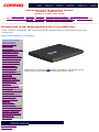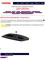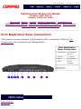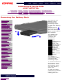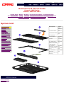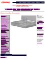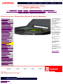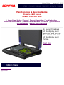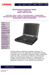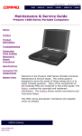
1
United States
January 2, 2003
Maintenance & Service Guide
Presario 1600 Series
Models: 1650 and 1655
| Home Page | Notice | Preface | Product Description | Troubleshooting
Illustrated Parts Catalog | Removal & Replacement Procedures | Specifications
Pin Assignments | Battery Pack Operations
Notice
Preface
Product
Description
Troubleshooting
Illustrated Parts
Catalog
Removal &
Replacement
Procedures
Specifications
Connector Pin
Assignments
Battery Pack
Operations
Welcome to the Maintenance & Service Guide (MSG). This online
guide is designed to serve the needs of those whose job it is to repair
Compaq products. Many of the components of the hardcopy MSG are
contained in this online guide. The Notice, contains the copyright and
trademark information. The Preface shows symbol conventions,
Technician Notes and Serial Number locations on the unit.
This MSG will be periodically maintained and updated online as
needed. For content comments or questions, contact the Editor.
To report a technical problem, contact your Regional Support Center
or IM Help Center.
privacy and legal statement
United States
January 2, 2003
Maintenance & Service Guide
Presario 1600 Series
Models: 1650 and 1655
| Home Page | Notice | Preface | Product Description | Troubleshooting
Illustrated Parts Catalog | Removal & Replacement Procedures | Specifications
Pin Assignments | Battery Pack Operations
Notice
The information in this guide is subject to change without notice.
COMPAQ COMPUTER CORPORATION SHALL NOT BE LIABLE FOR TECHNICAL OR
EDITORIAL ERRORS OR OMISSIONS CONTAINED HEREIN, NOR FOR INCIDENTAL
OR CONSEQUENTIAL DAMAGES RESULTING FROM THE FURNISHING,
PERFORMANCE, OR USE OF THIS MATERIAL.
This guide contains information protected by copyright. No part of this guide may be
photocopied or reproduced in any form without prior written consent from Compaq
Computer Corporation.
Ó 1998 Compaq Computer Corporation.
All rights reserved. Printed in the U.S.A.
Compaq, Presario Registered U. S. Patent and Trademark Office.
Microsoft, MS-DOS, and Windows are registered trademarks of Microsoft Corporation.
Windows 95 is a trademark of Microsoft Corporation.
The software described in this guide is furnished under a license agreement or
nondisclosure agreement. The software may be used or copied only in accordance with
the terms of the agreement.
Product names mentioned herein may be trademarks and/or registered trademarks of
their respective companies.
Maintenance and Service Guide
Compaq Presario 1600 Series Portable Computers
First Edition (June 1998)
Compaq Computer Corporation
privacy statement
legal notices
United States
January 2, 2003
Maintenance & Service Guide
Presario 1600 Series
Models: 1650 and 1655
| Home Page | Notice | Preface | Product Description | Troubleshooting
Illustrated Parts Catalog | Removal & Replacement Procedures | Specifications
Pin Assignments | Battery Pack Operations
Preface
This Maintenance and Service Guide is a troubleshooting guide that can be used for reference when
servicing the Compaq Presario 1600 Series Portable Computers.
Compaq Computer Corporation reserves the right to make changes to the Compaq Presario 1600
Series Portable Computers without notice.
Symbols
The following words and symbols mark special messages throughout this guide.
WARNING: Text set off in this manner indicates that failure to follow directions in the warning could result in bodily harm or loss of
life.
CAUTION: Text set off in this manner indicates that failure to follow directions could result in damage to equipment or loss of data.
IMPORTANT:
NOTE:
Text set off in this manner presents clarifying information or specific instructions.
Text set off in this manner presents commentary, sidelights, or interesting points of
information.
Technician Notes
WARNING: Only authorized technicians trained by Compaq should repair this equipment. All troubleshooting and repair procedures
are detailed to allow only subassembly/module level repair. Because of the complexity of the individual boards and subassemblies,
the user should not attempt to make repairs at the component level or to make modifications to any printed circuit board. Improper
repairs can create a safety hazard. Any indications of component replacement or printed circuit board modifications may void any
warranty
Serial Number
When requesting information or ordering spare parts, the computer serial number should be
provided to Compaq. The serial number is located on the bottom of the computer.
Locating Additional Information
The following documentation is available to support this product:
●
●
●
●
●
●
Compaq Presario 1600 Series Portable Computer documentation set
Introducing Windows 98 Guide
Service Training Guides
Compaq Service Advisories and Bulletins
Compaq QuickFind
Compaq Service Quick Reference Guide
privacy statement
legal notices
United States
January 2, 2003
Maintenance & Service Guide
Presario 1600 Series
Models: 1650 and 1655
| Home Page | Notice | Preface | Product Description | Troubleshooting
Illustrated Parts Catalog | Removal & Replacement Procedures | Specifications
Pin Assignments | Battery Pack Operations
Product Description
Models and
Features
Controls and
Lights
Left Side
Components
Right Side
Components
Bottom of
Unit
Rear
Connectors
Port
Replicator
Power
Management
for Windows
98
privacy statement
legal notices
Compaq
Presario
1600 Series
Portable
Computer is
a
continuation
of the new
generation
of
multimedia
portable
computers
with an
innovative
integrated
design,
outstanding
audio and
video,
advanced
core
features,
and
attractive
styling. This
fullfunction,
Pentium II based series
of portable
computers
allows full
desktop
functionality
and
additional
connectivity
via the
optional
port
replicator.
United States
January 2, 2003
Maintenance & Service Guide
Presario 1600 Series
Models: 1650 and 1655
| Home Page | Notice | Preface | Product Description | Troubleshooting
Illustrated Parts Catalog | Removal & Replacement Procedures | Specifications
Pin Assignments | Battery Pack Operations
Troubleshooting
Preliminary Steps
Clearing the Power-On
Password
Power-On Self Test
(POST)
Compaq Diagnostics
Diagnostic Error Codes
Troubleshooting
Without Diagnostics
Solving Minor
Problems
Contacting Compaq
Support
This section covers troubleshooting information for the
Compaq Presario 1600 Series Portable Computers. The
basic steps in troubleshooting include:
1. Follow the Preliminary Steps.
2. Run the Power-On Self-Test
(POST).
3. Follow the recommended
actions described in the
diagnostic tables, if you are
unable to run POST or if POST
displays an error message.
When following the recommended
actions in the Sections on POST
and Diagnostic Error Codes
perform them in the order listed.
Rerun POST after each
recommended action until the
problem is solved and no error
message occurs. Once the
problem is solved, do not
complete the remaining
recommended actions.
If the problem is
intermittent, check the
NOTE: computer several times to
verify that the problem is
solved.
privacy statement
legal notices
United States
January 2, 2003
Maintenance & Service Guide
Presario 1600 Series
Models: 1650 and 1655
| Home Page | Notice | Preface | Product Description | Troubleshooting
Illustrated Parts Catalog | Removal & Replacement Procedures | Specifications
Pin Assignments | Battery Pack Operations
Illustrated Parts Catalog
System Unit
Boards
Display
Assembly
Mass Storage
Devices
Miscellaneous
Cable Kit
Cables
Miscellaneous
Hardware and
Plastics Kit
Miscellaneous
Parts
Documentation
and Software
privacy statement
legal notices
This section provides an breakdown and identifies the spare parts
ordering number associated with each item(s) for the Compaq Presario
1600 Series Portable Computers.
United States
January 2, 2003
Maintenance & Service Guide
Presario 1600 Series
Models: 1650 and 1655
| Home Page | Notice | Preface | Product Description | Troubleshooting
Illustrated Parts Catalog | Removal & Replacement Procedures | Specifications
Pin Assignments | Battery Pack Operations
Removal and Replacement Procedures
This section explains the removal and replacement procedures for the
computer.
Serial Number Location
Disassembly
Sequence
Electrostatic
Discharge
Service
Considerations
Cables and
Connectors
Preparing the
Computer for
Disassembly
Battery Pack
Palmrest
Cover with
Touch Pad
Keyboard
Heatspreader
Modem
Processor
Status Panel
Interface
Board
Hard Drives
Battery
Charger Board
CD Drive
Display Panel
Assembly
Upper CPU
Cover
Speaker
Assembly
Diskette Drive
Fan Assembly
Audio Board
System Board
Memory
Module
privacy statement
legal notices
Report the computer
serial number to Compaq when
requesting information or ordering spare parts.
United States
January 2, 2003
Maintenance & Service Guide
Presario 1600 Series
Models: 1650 and 1655
| Home Page | Notice | Preface | Product Description | Troubleshooting
Illustrated Parts Catalog | Removal & Replacement Procedures | Specifications
Pin Assignments | Battery Pack Operations
Specifications
This chapter covers the following specifications of Compaq Presario 1600 Series Portable
Computers:
●
Computer models
●
Physical and environmental
●
System Interrupts
●
System DMA
●
System I/O Address
●
System Memory Catalog
●
Display
●
Memory expansion
●
Diskette drive
●
Hard drive
●
CD drive
●
Battery pack
Physical and Environmental
Computer Specifications
U.S.
Metric
1.97 in
12.20 in
10.08 in
4.95 cm
31.00 cm
25.40 cm
Model 1650
Model 1655
7.326 Ib
7.326 Ib
3.33 kg
3.33 kg
Stand-Alone (Battery Pack)
Power Requirements
NiMH
Li-ion
Nominal Operating
Maximum Average
Peak Operating
W @ 9.6 V
W @ 9.6 V
W @ 9.6 V
W @ 14.4 V
W @ 14.4 V
W @ 14.4 V
Dimensions
Height
Depth
Width
Weight
AC Power Requirements
Operating Voltage
Operating Current
Operating Frequency
100-240 V
0.8/0.4 A RMS
47-63 Hz
Meets IEC 801-4 and IEC801-5
1kV for 50 ns
Maximum Transient
Temperature
Operating
50° to 95 °F
10° to 35 °C
Nonoperating
-4° to 140 °F
-20° to 60 °C
Operating
10 to 90%
35°C to 90%
Nonoperating (tw = 38.7°C max)
5 to 95%
60°C to 95%
Operating
0 to 10,000 ft
0 to 3.15 km
Nonoperating
0 to 30,000 ft
0 to 9.14 km
Relative Humidity
(noncondensing)
Altitude
Shock
Operating
10 G, 11 ms, half sine
Non operating
240 G, 2 ms, half sine
Vibration
Operating
0.5 G
Nonoperating
1.5 G
NOTE: Applicable product safety standards specify thermal limits for plastic surfaces.
Compaq Presario 1600 Series Portable Computers operate well within this range of
temperatures.
System Interrupts
System Interrupts
Hardware IRQ
System Function
IRQ0
Timer Interrupt
IRQ1
Keyboard
IRQ2
Interrupt Controller Cascade
IRQ3
Internal Modem
IRQ4
Communication Port (COM1)
IRQ5
Audio Controller
IRQ6
Diskette Drive
IRQ7
Parallel Port (LPT 1) (default)
IRQ8
System CMOS/Real-Time Clock
IRQ9
IRQ Holder for PCI Steering
IRQ9
PCI-1131 CardBus Controller
IRQ9
IRQ Holder for PCI Steering
IRQ9
IRQ Holder for PCI Steering
IRQ9
PCI-1131 CardBus Controller
IRQ9
Video Controller
IRQ11
Intel PCI to USB Universal Host Controller
IRQ11
IRQ Holder for PCI Steering
IRQ12
PS/2 TouchPad/Mouse
IRQ13
Numeric data processor
IRQ14
Intel PCI Bus Master IDE Controller
IRQ14
Primary IDE Controller (dual fifo)
IRQ15
Intel PCI Bus Master IDE Controller
IRQ15
Secondary IDE Controller (dual fifo)
System DMA
System DMA
Hardware DMA
System Function
DMA 0
Audio Controller
DMA 1
Audio Controller
DMA 2
Diskette Drive
DMA 4
DMA Controller
System I/O Address
System I/O Address
I/O Address (Hex)
System Function (Shipping Configuration)
0000h-000Fh
DMA Controller
0020h-0021h
Interrupt Controller
0040h-0043h
System timer
0060h-0060h
Keyboard Controller
0061h-0061h
System speaker
0064h-0064h
Standard 101/102-Key or Microsoft Natural
Keyboard
0070h-0071h
System CMOS/real time clock
0080h-0080h
Motherboard resources
0081h-008Fh
DMA Controller
00A0h-00A1h
Programmable interrupt controller
00C0h-00DFh
DMA
00ECh-00EFh
Motherboard resources
00F0h-00FFh
Numeric data processor
0170h-0177h
Intel PCI Bus Master IDE Controller
0170h-0177h
Secondary IDE Controller (dual fifo)
01F0h-01F7h
Intel PCI Bus Master IDE Controller
01F0h-01F7h
Primary IDE Controller (dual fifo)
0201h-0201h
Gameport Joystick
0220h-022Fh
ES1869 Plug and Play AudioDrive
02F8h-02FFh
Compaq Presario 56K-DF
0330h-0331h
ES1869 Plug and Play AudioDrive
0376h-0376h
Secondary IDE controller (dual fifo)
0376h-0376h
Intel PCI Bus Master IDE Controller
0378h-037Fh
Printer Port (LPT1)
0388h-038Bh
ES1869 Plug and Play AudioDrive
03B0h-03BBh
Video Controller
03C0h-03DFh
Video Controller
03F0h-03F5h
Standard Floppy Disk Controller
03F6h-03F6h
Intel PCI Bus Master IDE Controller
03F6h-03F6h
Primary IDE controller (dual fifo)
03F7h-03F7h
Standard Floppy Disk Controller
03F8h-03FFh
Communications Port (COM1)
04D0h-04D1h
Motherboard resources
0800h-0807h
ES1869 Control Interface
0CF8h-0CFFh
PCI bus
2180h-218Fh
Motherboard resources
8000h-803Fh
Motherboard resources
FCD0h-FCD7h
Primary IDE controller (dual fifo)
FCD0h-FCDFh
Intel PCI Bus Master IDEController
FCD8h-FCDFh
Secondary IDE controller (dual fifo)
FCE0h-FCFFh
Intel PCI to USB Universal Host Controller
System Memory Catalog
System Memory Catalog
Memory Address
System Function
00000000h-0009FFFFh
System board extension for PnP BIOS
000A0000h-000AFFFFh
Graphics Controller
000B0000h-000BFFFFh
Graphics Controller
000C0000h-000CBFFFh
Graphics Controller
000DC000h-000FFFFFh
System board extension for PnP BIOS
00100000h-03FFFFFFh
System board extension for PnP BIOS
05000000h-05000FFFh
PCI-1131 CardBus Controller
05001000h-05001FFFh
PCI-1131 CardBus Controller
80000000h-803FFFFFh
Intel Pentium(r) II Processor to PCI bridge
FD000000h-FDFFFFFFh
Graphics Controller
FEA00000h-FEBFFFFFh
Graphics Controller
FED00000h-FEDFFFFFh
Graphics Controller
FFF80000h-FFFFFFFFh
Motherboard resources
Display (Information not available)
13.3" (Diagonal) TFT Display
U.S.
Metric
Information
not available
Information
not available
Information
not available
Information
not available
Weight
Information
not available
Information
not available
Contrast Ratio
Information
not available
Information
not available
Brightness
Information
not available
Information
not available
Total Power Consumption
Information
not available
Information
not available
Dimensions
Height
Width
Display Dimensions
Width
Height
Depth
12.1" (Diagonal) TFT Display
U.S.
Metric
Information
not available
Information
not available
Information
not available
Information
not available
Weight
Information
not available
Information
not available
Contrast Ratio
Information
not available
Information
not available
Brightness
Information
not available
Information
not available
Total Power Consumption
Information
not available
Information
not available
Dimensions
Height
Width
Display Dimensions
Width
Height
Depth
Memory Expansion
Memory Expansion
System Memory
Expansion Board
Memory
Total Memory
32-MB
16-MB
48-MB
32-MB
32-MB
64-MB
32-MB
64-MB
96-MB
Diskette Drive (Information not available)
Diskette Drive
Capacity per Diskette (High/Low)
Information not available
Diskette Size
Information not available
Number of LED Indicators
(Read/Write)
Information not available
Number of Drives Supported
Information not available
Drive Rotation (rpm)
Information not available
Transfer Rate (Kbps)
Information not available
Bytes per Sector
Information not available
Sectors per Track (High/Low)
Information not available
Tracks per Side (High/Low)
Information not available
Access Times
Information not available
Track-to-Track (ms)
Average (ms)
Setting Time (ms)
Latency Average (ms)
Cylinders (High/Low)
Information not available
Number of Read/Write Heads
Information not available
Hard Drive (Information not available)
Hard Drives
5.0-GB
4.0-GB
Capacity Per Drive
Information not available Information not available
Drive Type
Information not available Information not available
Logical Configuration
Cylinders
Heads
Sectors per track
Bytes per sector
Information not available Information not available
Seek Times
(Typical, Including settling in
ms)
Single track
Average
Full stroke
Information not available Information not available
Transfer Rate
At interface
Information not available Information not available
CD Drive (Information not available)
CD Drive
24× CD Drive
Dimensions
Information not available
Weight
Information not available
Rotational Speed
Information not available
Typical Transfer Rate
Sustained Data Transfer Rate
Information not available
Access Time
Average Random Access Time
Information not available
Spin Up time
Information not available
Data Buffer Capacity
Information not available
Battery Pack
Battery Pack
Nickel Metal Hydride (NiMH) Lithium Ion (Li ion) *
Dimensions
Height
Length
Width
0.8 in (20.3 mm)
5.7 in (145 mm)
3.1 in (78.7 mm)
0.8 in (20.3 mm)
5.7 in (145 mm)
3.1 in (78.7 mm)
Weight
1.01 Ib (458.1 g)
0.90 Ib (408.2 g)
Battery Pack Operating
Time
2:30 hr
3:00 hr
9.6 V
3200mAH
40 W
14.4 V
2500mAH
40 W
32° F (0-50° C)
-20° C -60° C
5° C-45° C
32° F (0-50° C)
-20° C -60° C
5° C-45° C
Energy
Nominal Open Circuit Voltage
Capacity
Power
Environmental
Requirements
Operating Temperature
Non-operating Temperature
Charging Temperature
privacy statement
legal notices
Maintenance & Service Guide
Presario 1600 Series
Models: 1650 and 1655
| Home Page | Notice | Preface | Product Description | Troubleshooting
Illustrated Parts Catalog | Removal & Replacement Procedures | Specifications
Pin Assignments | Battery Pack Operations
Connector Pin Assignments
This appendix provides connector pin assignment tables for Compaq Presario 1600
Series Portable Computers. For more information on connectors, refer to the section
on Rear Connectors.
NOTE: The signals in all tables of this appendix are considered active high unless
otherwise indicated by an asterisk (*).
Parallel Connector
Pin
Signal
Pin
Signal
1
Strobe*
10
Acknowledge*
2
Data Bit 0
11
Busy
3
Data Bit 1
12
Paper Out
4
Data Bit 2
13
Select
5
Data Bit 3
14
Auto Linefeed*
6
Data Bit 4
15
Error*
7
Data Bit 5
16
Initialize Printer*
8
Data Bit 6
17
Select In*
9
Data Bit 7
18-25
Signal Ground
* = Active low
Serial Connector
Connector
Pin
Signal
1
Carrier Detect
2
Receive Data
3
Transmit Data
4
Data Terminal Ready
5
Signal Ground
6
Data Set Ready
7
Ready to Send
8
Clear to Send
9
Ring Indicator
Keyboard/Mouse
Connector
Pin
Signal
1
Data
2
Not defined
3
Ground
4
+5 VDC
5
Clock
6
Not defined
External VGA Monitor
Connector
Pin
Signal
1
Red Analog
2
Green Analog
3
Blue Analog
4
Not connected
5
Ground
6
Ground Analog
7
Ground Analog
8
Ground Analog
9
Not connected
10
Ground
11
Monitor Detect
12
DDC2B Data
13
Horizontal Sync
14
Vertical Sync
15
DDC2B Clock
Universal Serial Bus
Connector
Pin
Signal
1
Ground
2 D+
3 D4 Power
Port Replicator
Pin Signal
Pin Signal
Pin Signal
Pin Signal
1
N.C.
21
Printer Data 0
41
N.C.
61
CTS
2
N.C.
22
Printer Data 1
42
N.C.
62
DCD
3
Kb Clk 1
23
Printer Data 2
43
Switch A
63
DSR
4
Joystick Data A 24
Printer Data 3
44
Switch B
64
TXD
5
Kb Data 1
25
Printer Data 4
45
Switch C
65
RTS
6
Joystick Data B 26
Printer Data 5
46
Switch D
66
N.C.
7
Kb Clk 2
27
Printer Data 6
47
N.C.
67
Detect
8
Joystick Data C 28
Printer Data 7
48
MIDI In
68
N.C.
9
Kb Data 2
USB 0 -
49
MIDI Out
69
V. Sync
10
Joystick Data D 30
USB 0 +
50
+5V
70
Ground
11
Lp Select In
31
USB 1 -
51
+5V
71
H. Sync
12
Lp Paper End
32
USB 1+
52
N.C.
72
Ground
13
Lp Initialize
33
Adapter In
53
N.C.
73
Blue
14
Lp Busy
34
Adapter In
54
N.C.
74
Ground
15
Lp Error
35
Adapter In
55
N.C.
75
Green
16
Lp Ack
36
Adapter In
56
Dock ID -
76
Ground
17
Lp Auto Feed
37
Adapter In
57
RXD
77
Red
18
Lp Strobe
38
Adapter In
58
Lp Select
78
Ground
19
DDC2BC
39
N.C.
59
RI
79
N.C.
20
DDC2BD
40
N.C.
60
DTR
80
N.C.
29
Modem
Connector
privacy statement
legal notices
Pin
Signal
1
Unused
2
Unused
3
Tip
4
Ring
5
Unused
6
Unused
United States
January 2, 2003
Maintenance & Service Guide
Presario 1600 Series
Models: 1650 and 1655
| Home Page | Notice | Preface | Product Description | Troubleshooting
Illustrated Parts Catalog | Removal & Replacement Procedures | Specifications
Pin Assignments | Battery Pack Operations
Battery Pack Operating Time
This appendix covers the following information concerning battery pack operating time:
●
●
●
Increase battery pack operating time
Conditioning a battery pack
Disposal of a used battery pack
Increasing Battery Pack Operating Time
Battery pack operating time differs depending on several variables. To avoid unnecessary
replacement, consider the following variables when determining how long a charged battery pack
should last:
●
Power management settings
●
Hardware configuration
●
Software applications
●
Installed options
●
Display brightness
●
Hard drive usage
●
Changes in operating temperature
●
Type and number of installed PC Cards
NOTE:
The power consumption requirements for PC Cards vary widely. Some cards drain
the battery pack very rapidly.
Battery pack operating time can be increased by as much as 50 percent by controlling the energy
required by the computer and the energy stored in the battery pack.
Minimizing the Energy Required
To minimize the energy required by the computer, follow these steps:
●
●
Set the power conservation levels in the Power Management utility to Maximum.
Customize the timeout value to work more efficiently with the applications. The
amount of battery life depends on the values selected.
Maximizing the Energy Stored
To maximize the energy stored in the battery pack, follow these guidelines:
●
●
●
Condition the battery pack at least every 30 days to improve overall battery
performance.
Keep a battery pack in the computer when using it with AC power to supply the
battery pack with a constant trickle charge.
Store the battery pack in a cool, dry place when not in use.
Conditioning a Battery Pack
CAUTION: To avoid a loss of data, ensure that all data is saved before discharging a
battery pack.
To condition a battery pack, complete the following steps:
1. Plug in the AC adapter and allow the battery to charge until the fast charge arrow on
the display disappears. Your battery gauge may read 100 percent for a period of time
before the arrow disappears. Do not unplug the AC adapter until the arrow disappears.
2. Unplug the AC adapter and allow the battery to drain until the computer reaches
hibernation and turns itself off. Do not plug in the AC adapter during this process
or you will need to restart with Step No. 1. You may use the computer while the
battery is draining.
3. Your battery is re- conditioned.
4. Plug in the AC adapter and begin using the computer.
The table below shows battery pack charge times by model.
Battery Charge Time
Computer
On Line
Off Line
Model 1/NiMH Battery Pack
4.0 hours premature termination
2:00 hr
Model 2/Li ion Battery Pack
4.5 hours premature termination
2:50 hr
Disposal of a Used Battery Pack
In the interest of safeguarding our environment. Compaq Computer Corporation recommends that
nickel metal hydride (NiMH) and lithium ion (Li ion) battery packs be recycled. Battery packs
should be handled in accordance with country, state, province, or local regulations.
CAUTION: Never attempt to open or service a battery pack. Opening a battery pack
not only damages the pack and makes it unusable, but also expose potentially harmful
battery components.
Top of Page
privacy statement
legal notices
United States
January 2, 2003
Maintenance & Service Guide
Presario 1600 Series
Models: 1650 and 1655
| Home Page | Notice | Preface | Product Description | Troubleshooting
Illustrated Parts Catalog | Removal & Replacement Procedures | Specifications
Pin Assignments | Battery Pack Operations
Models and Features
Compaq Presario 1600
Series Portable Computer Models
Models and
Features
Controls and
Lights
Left Side
Components
Right Side
Components
Bottom of
Unit
Rear
Connectors
Port
Replicator
Power
Management
for Windows
98
privacy statement
legal notices
Model
1650
Model
1655
Display
12. 1" TFT
13. 3" TFT
Processor
266 Pentium II
266 Pentium II
Hard Drive
4.0-GB
4.0-GB
CD Drive
24× MAX
24× MAX
Modem
M+-56.0 Kbps or K56.0 Kbps with ITU
V.90
K-56.0 Kbps with
ITU V.90
United States
January 2, 2003
Maintenance & Service Guide
Presario 1600 Series
Models: 1650 and 1655
| Home Page | Notice | Preface | Product Description | Troubleshooting
Illustrated Parts Catalog | Removal & Replacement Procedures | Specifications
Pin Assignments | Battery Pack Operations
Controls and Lights
Models and
Features
Controls and
Lights
Left Side
Components
Right Side
Components
Bottom of
Unit
Rear
Connectors
Port
Replicator
Power
Management
for Windows
98
Front of Unit
1. Display 9.CD
Previous
Track
2. Power
(On/Off)
Button
10. CD
Next
Track
3.
DisqPlay
Switch
11.
Keyboard
4.Volume
Control
Down
Button
12. Touch
Pad
5. Volume 13. Left
Control Up Touch Pad
Button
Button
6. Status
Panel
14. Right
Touch Pad
Button
7. CD
15.
Play/Pause Integrated
Speakers
8. CD
Stop
privacy statement
legal notices
United States
January 2, 2003
Maintenance & Service Guide
Presario 1600 Series
Models: 1650 and 1655
| Home Page | Notice | Preface | Product Description | Troubleshooting
Illustrated Parts Catalog | Removal & Replacement Procedures | Specifications
Pin Assignments | Battery Pack Operations
Left Side Components
Models and
Features
Controls and
Lights
Left Side
Components
Right Side
Components
Bottom of
Unit
Rear
Connectors
Port
Replicator
Power
Management
for Windows
98
privacy statement
legal notices
1.
Modem
Jack
2.
Diskette
Drive
Slot
3.
Diskette
Eject
Button
4.
Battery
Pack
5. Left
Speaker
Port
United States
January 2, 2003
Maintenance & Service Guide
Presario 1600 Series
Models: 1650 and 1655
| Home Page | Notice | Preface | Product Description | Troubleshooting
Illustrated Parts Catalog | Removal & Replacement Procedures | Specifications
Pin Assignments | Battery Pack Operations
Right Side Components
Models and
Features
Controls and
Lights
Left Side
Components
Right Side
Components
Bottom of
Unit
Rear
Connectors
Port
Replicator
Power
Management
for Windows
98
privacy statement
legal notices
1.
Headphone
Out
6. Manual
Eject Hole
2.Line-In Jack 7. PCMCIA
(Top Slot)
3. External
Microphone
Jack
8.PCMCIA
(Bottom Slot)
4. CD Drive
9.PCMCIA
Eject Levers
5. CD Drive
Eject Button
10. Right
Speaker Port
United States
January 2, 2003
Maintenance & Service Guide
Presario 1600 Series
Models: 1650 and 1655
| Home Page | Notice | Preface | Product Description | Troubleshooting
Illustrated Parts Catalog | Removal & Replacement Procedures | Specifications
Pin Assignments | Battery Pack Operations
Bottom of Unit
Models and
Features
Controls and
Lights
Left Side
Components
Right Side
Components
Bottom of
Unit
Rear
Connectors
Port
Replicator
Power
Management
for Windows
98
privacy statement
legal notices
1. Memory
2.
Compartment Feet
United States
January 2, 2003
Maintenance & Service Guide
Presario 1600 Series
Models: 1650 and 1655
| Home Page | Notice | Preface | Product Description | Troubleshooting
Illustrated Parts Catalog | Removal & Replacement Procedures | Specifications
Pin Assignments | Battery Pack Operations
Rear Connectors
Models and
Features
1.Keyboard/Mouse
Port
6. External Monitor
Port
Controls and
Lights
2. Parallel Printer
Port
7. USB
Left Side
Components
3. Port Replicator
8. AC Adapter
4. Fan Exhaust
9. Security Slot
Right Side
Components
Bottom of
Unit
Rear
Connectors
Port
Replicator
Power
Management
for Windows
98
privacy statement
legal notices
5. Serial Port
United States
January 2, 2003
Maintenance & Service Guide
Presario 1600 Series
Models: 1650 and 1655
| Home Page | Notice | Preface | Product Description | Troubleshooting
Illustrated Parts Catalog | Removal & Replacement Procedures | Specifications
Pin Assignments | Battery Pack Operations
Port Replicator
Models and
Features
Controls and
Lights
Left Side
Components
Right Side
Components
Bottom of
Unit
Rear
Connectors
Port
Replicator
Power
Management
for Windows
98
This section is an overview of the Compaq Presario 1600 Series Portable
Computer Port Replicator and covers the following topics:
■
■
■
■
System Overview
A manual docking mechanism on the Compaq Presario 1600 Series Portable
Computer Port Replicator docks Compaq Presario 1600 Series Portable
Computers. When the computer is docked, the 80-pin external options connector
handles the entire electrical interface (both power and signal connections)
between the computer and the Port Replicator Rear.
Features
The Compaq Presario 1600 Series Portable Computer Port Replicator provides
all the connectors supported by the Compaq Presario 1600 Series Portable
Computers. They include:
■
■
■
■
■
■
■
■
Revised: dd Month 1998
privacy statement
legal notices
System Overview
Features
Port Replicator Rear Connectors
80-Pin Connectors
External keyboard
External mouse
MIDI/game port
External monitor
Serial
Parallel
AC Adapter
Dual USB ports (Not supported on all models.)
United States
January 2, 2003
Maintenance & Service Guide
Presario 1600 Series
Models: 1650 and 1655
| Home Page | Notice | Preface | Product Description | Troubleshooting
Illustrated Parts Catalog | Removal & Replacement Procedures | Specifications
Pin Assignments | Battery Pack Operations
80-Pin Port Replicator Connector
The 80-pin Compaq Presario 1600 Series Portable Computer Port Replicator
connector handles the entire electrical interface between the port Replicator
and the computer.
CAUTION: Turn the computer power switch off before you connect or disconnect the
port Replicator. Damage may occur to the computer if it is "hot" plugged to the port
Replicator.
privacy statement
legal notices
United States
January 2, 2003
Maintenance & Service Guide
Presario 1600 Series
Models: 1650 and 1655
| Home Page | Notice | Preface | Product Description | Troubleshooting
Illustrated Parts Catalog | Removal & Replacement Procedures | Specifications
Pin Assignments | Battery Pack Operations
Port Replicator Rear Connectors
This section covers external input/output (I/O) connectors. Refer to Pin
Assignments for connector pin assignments.
Port Replicator
Rear Connectors
1. Keyboard
6. External
Monitor
2. Mouse
7. Serial
3. USB
8. Parallel
4. USB
9. AC
Adapter
5.
MIDI/Game
Pad/Joystick
privacy statement
legal notices
United States
January 2, 2003
Maintenance & Service Guide
Presario 1600 Series
Models: 1650 and 1655
| Home Page | Notice | Preface | Product Description | Troubleshooting
Illustrated Parts Catalog | Removal & Replacement Procedures | Specifications
Pin Assignments | Battery Pack Operations
Power Management for Windows 98
The following power management features are available for conserving AC power and extending
battery operating time:
Power Management Settings
Sleep
Hibernation
Battery operating time
Rebooting After a Lockup
Servicing Your Computer - Full Off Mode
●
●
●
●
●
●
Power Management Settings
Depending on your patterns of computer use, you can set different levels of power management.
These different power management levels can be activated based on the amount of time passed
since the last system activity. System activity examples, include keyboard or mouse movement,
CD (while under program control that monitors Sleep), and modem use.
You can select different conditions or power schemes through Power Management..The optional
settings are Home/Office Desk, Portable/ Laptop and Always On. From the default settings,
you can change the following settings.
●
●
●
the System goes to Sleep (Standby) mode
the screen times out and goes blank
the hard drive spins down
Each of these system components will go to sleep after the selected or default periods of inactivity.
(The setting for hard drive must be less than or equal to the setting for System.)
IMPORTANT:
If you're on a network, it's recommended that you set System Standby to
Never.
There are five categories of power management settings under the Control Panel. The default
setting for each feature is listed below in the tables.
Power Management Properties
Tab: Power Schemes:
Plugged in
Always on System
Standby:
Turn OFF Monitor
Always on System
Standby:
Never
Running on
Batteries
15 minutes
After 15 minutes
After 15 minutes
After 10 minutes
After 10 minutes
Power Management Properties
Tab: ALARMS::
Low Battery Alarm:
Critical Battery Alarm
Alarm Actions:
10%
0%
X Display Message Notification
Text Action
No Action
Power Management Properties
Tab: POWER METER:
Tab: ADVANCED
Default
Default
Display Properties
Tab: POWER METER: Monitor Laptop Display (Maximum resolution according to
unit display size)
System Properties
Tab: Device Manager
Default:
Disk Drives:
CD ROM:
X DMA
X DMA
Sleep
You can select Sleep mode instead of turning off the computer when you have finished using it.
This allows the computer to wake up faster than turning it completely off and saves power over the
active (On) mode. Compaq Presario Notebook computers have two levels of sleep, Hibernation and
Sleep.
Hibernation - by pushing the power button once your computer will perform a save to disk
followed by a shut down of the computer into Off mode.
Sleep - is a low power mode, also referred to as Standby mode. While in Sleep mode, your
computer will maintain system information and open files. Unsaved information will be lost if you
turn off your system prior to system wake-up, or if you lose power while using the AC adapter.
While in Sleep mode, your computer will maintain system information and open
files. Unsaved information will be lost if you turn off your system prior to system wakeup, or if you lose power while using the AC adapter.
CAUTION:
Hibernation Mode
Hibernation helps conserve battery life and protects your data. Hibernation can be a routine power
saving event, or can be the result of a low battery condition. As it enters Hibernation, your
computer will display a progress screen, as it automatically saves the machine state before it shuts
down and turns itself off. Your computer will automatically go into Hibernation, when the battery
has little power left, or when the system (operating on battery power) has been in Sleep mode for
more than an hour. You can also manually initiate Hibernation by pressing the power button once
while the system is active. To restore the computer's previous state, simply press the power button
once again. While waking up, the computer will display a progress screen.
The following table shows the conditions and indicators for getting in and out of the various power
management modes, Sleep, Hibernation and Off.
Mode
To Initiate
To End
Indicators
Sleep
Manual keys
combination
- Fn+F4
Press any key
Flashing green
Power LED
Press Power
Button once
No Power LED,
blank screen
Perform normal Press Power
Windows
Button once
shutdown via
the start
button, or press
and hold down
the power
button for 4
seconds
No Power LED,
blank screen
Time Out
Default 15
minutes. If on
Battery power
(system will not
go to Sleep if
on AC power)
Hibernate
Manual - Press
Power Button
once
Time Out
Default If low
battery or after
1 hour of sleep
(system will not
Hibernate if on
AC power)
Off
Servicing Your Computer - Full Off Mode
If you need to install or replace components in your system, you must turn the computer off
completely. Follow the instructions above for properly putting the computer into Off mode, unplug
from the outlet and remove the battery (see battery section for instruction on removing battery).
Rebooting After a Lockup
Occasionally you may encounter a frozen keyboard or a locked screen. To reboot your computer
(as if from a cold start) press and hold down the Power Button for at least four seconds, which will
cause a manual shutdown. Then, restart it with a single press of the Power Button. If it still doesn't
recover, press the Power Button and hold it for four seconds to shut it down, then, remove the
battery or unplug the AC power for at least 30 seconds. Reinsert the battery or reconnect AC
power and press the Power Button once to reboot.
Battery Operating Time
Battery operating time is affected by variables, such as the following:
●
Power conservation settings
●
Hardware configuration
●
Software applications
●
Installed options
●
Display brightness
●
Hard drive usage
●
Power button
●
Changes in operating temperature
●
Type and number of installed PC Cards
For more information on increasing battery pack operating time, conditioning the battery pack, and
disposing of a used battery pack, refer to the Battery Pack Operations.
privacy statement
legal notices
United States
January 2, 2003
Maintenance & Service Guide
Presario 1600 Series
Models: 1650 and 1655
| Home Page | Notice | Preface | Product Description | Troubleshooting
Illustrated Parts Catalog | Removal & Replacement Procedures | Specifications
Pin Assignments | Battery Pack Operations
Removing the Battery Pack
Electrostatic
Discharge
Service
Considerations
Cables and
Connectors
Preparing the
Computer for
Disassembly
Battery Pack
Palmrest
Cover with
Touch Pad
Keyboard
Heatspreader
Modem
Processor
Status Panel
Interface
Board
Hard Drives
Battery
Charger Board
CD Drive
Display Panel
Assembly
Upper CPU
Cover
Speaker
Assembly
Diskette Drive
Fan Assembly
Audio Board
System Board
Memory
Module
To remove the
battery pack,
complete the
following steps:
1.Slide the battery
pack
compartment
door down and
pull the battery
pack forward from
the chassis.
To replace the
battery pack,
reverse the
procedure.
The
replacement
battery
pack will
come with a
removable
door. To
NOTE:
properly
replace the
battery
pack follow
the
instructions
below.
To replace a
new battery pack,
complete the
following steps:
1. Push forward on
the battery pack
with tab to insert
the battery pack
into the battery
pack slot.
2. Slide the battery
pack door up onto the
opening for the
battery pack door.
privacy statement
legal notices
United States
January 2, 2003
Maintenance & Service Guide
Presario 1600 Series
Models: 1650 and 1655
| Home Page | Notice | Preface | Product Description | Troubleshooting
Illustrated Parts Catalog | Removal & Replacement Procedures | Specifications
Pin Assignments | Battery Pack Operations
Preliminary Steps
Before running POST, complete the following preliminary steps:
1. If a power-on password has been established, type the password and press the Enter key. If
the password is not known, clear the password.
2. Run Computer Checkup.
3. Turn off the computer and its external devices.
4. Disconnect any external devices that you do not want to test. Do not disconnect the printer if
you want to test it or use it to log error messages.
If the problem only occurs when an external device is connected
to the computer, the problem may be related to the external
IMPORTANT:
device or its cable. Verify this by running POST with and without
the external device connected.
5. Install loopback plugs in the serial and parallel connectors if you would like to test these ports.
6. Ensure the hard drive is installed in the computer.
7. Ensure that the battery pack is inserted in the computer and the computer is connected to an
external AC power source.
When the preliminary steps are completed, you are ready to run POST.
privacy statement
legal notices
United States
January 2, 2003
Maintenance & Service Guide
Presario 1600 Series
Models: 1650 and 1655
| Home Page | Notice | Preface | Product Description | Troubleshooting
Illustrated Parts Catalog | Removal & Replacement Procedures | Specifications
Pin Assignments | Battery Pack Operations
Power-On Self Test (POST)
Running POST
To run POST, complete the following steps:
Turn off the computer, then turn on the computer.
If POST does not detect any errors, the computer will not beep. This indicates successful
completion of POST test. POST has run successfully and boots from the hard drive (or from a
bootable diskette if one is installed in the diskette drive).
If POST detects errors, the errors are indicated by screen and/or audible messages. Refer to
"Power-On Self-Test (POST) Codes" in the tables for a list of POST codes and their relevant
descriptions.
NOTE:
If the system is not functioning well enough to run POST, or if the display is not functioning
well enough to show POST error messages, refer to the Troubleshooting tables.
Power-On Self-Test Messages
102-System Board Failure
Probable Cause
Recommended Action
DMA, timers, etc.
Replace the system board.
162-System Options Not Set
Probable Cause
Recommended Action
Configuration incorrect
Run Computer Setup.
CMOS reflects that an invalid
configuration has been set.
Run Computer Setup.
RAM failure
1. Replace the memory modules.
2. Replace the system board.
Memory test data error
1. Replace the memory modules.
2. Replace the system board.
XX000YZZ RAM failure
Replace the system board.
XX000YZZ 201-Memory Error
Probable Cause
Recommended Action
301-Keyboard Error
Probable Cause
Recommended Action
Keyboard failure
1. Ensure the keys are not depressed during POST.
2. Reconnect the keyboard with the computer off.
3. Replace the keyboard.
304-Keyboard or System Unit Error
Probable Cause
Recommended Action
Keyboard or system board error
1. Replace the keyboard.
2. Replace the TouchPad or mouse.
3. Replace the system board.
601-Diskette Controller Error
Probable Cause
Recommended Action
Mismatch in drive type or failure in the
diskette controller
1. Run Computer Checkup (TEST).
2. Check and/or replace cables.
3. Replace the system board.
605-Diskette Drive Error
Probable Cause
Recommended Action
Mismatch in drive type
Run Computer Setup.
1780-Primary Hard Drive 0 Failure
Probable Cause
Recommended Action
Disk 0 failed to respond
1. Run Computer Checkup (TEST).
2. Replace the hard drive.
Hard drive format error
1. Run Computer Checkup (TEST).
2. Replace the hard drive.
1782-Hard Drive Controller
Probable Cause
Recommended Action
Hard drive controller failure
1. Run Computer Setup.
2. Replace the hard drive.
privacy statement
legal notices
United States
January 2, 2003
Maintenance & Service Guide
Presario 1600 Series
Models: 1650 and 1655
| Home Page | Notice | Preface | Product Description | Troubleshooting
Illustrated Parts Catalog | Removal & Replacement Procedures | Specifications
Pin Assignments | Battery Pack Operations
Clearing the Power-on Password
Clearing the power-on password
requires removing all Setup
attributes that are programmed
in the CMOS.
If the password is not known,
clear it by performing the
following steps:
1. Turn off the computer.
2. Disconnect the power cord.
3. Remove the battery pack.
4. Remove the keyboard.
RTC battery for
5. Remove the
30 seconds. The password,
together with other Setup
attributes, will be cleared.
6. Reassemble the computer.
7. Turn on the computer to verify
that the power-on password has
been cleared. If it has not been
cleared, repeat Steps 1 through
7.
privacy statement
legal notices
United States
January 2, 2003
Maintenance & Service Guide
Presario 1600 Series
Models: 1650 and 1655
| Home Page | Notice | Preface | Product Description | Troubleshooting
Illustrated Parts Catalog | Removal & Replacement Procedures | Specifications
Pin Assignments | Battery Pack Operations
Compaq Diagnostics
Compaq Diagnostics is installed on the hard drive of the computer. Run the
Diagnostics utilities when you want to view or test system information and if
you have installed or connected devices. If you run Compaq Diagnostics from
a diskette, ensure that it is version 10.11 or later.
The Diagnostics menu includes the following utilities:
■
■
■
Computer Checkup (TEST)
View System Information (INSPECT)
Prepare Computer for a Compaq Service Call (RemotePaq)
If you have a problem you cannot solve, run the Diagnostics utilities before
you call for support. Run Computer Checkup and select to save the device list
to a file and to print or to save the log of errors. Run the View System
Information (INSPECT) utility and select to print or to save that information.
Have the files or the printed information available when you call for support.
Computer Checkup (TEST)
Computer Checkup (TEST) determines whether the various computer
components and devices are recognized by the system and are functioning
properly. You can display, print, or save the information generated by
Computer Checkup.
Follow these steps to run Computer Checkup:
1. Plug the computer into an external power source. (A low battery condition
could interrupt the program.)
2. Turn on the external devices that you want to test. Connect the printer if
you want to print a log of error messages.
3. Insert the Compaq Diagnostics diskette in drive A.
4. Turn on or restart the computer. The computer starts from drive A, and the
Diagnostics Welcome screen appears.
5. Press Enter to continue. The Diagnostics menu appears.
6. Select Computer Checkup from the Diagnostics menu. A Test Option
menu appears.
7. Select View the Device List from the Test Option menu. A list of the
installed Compaq devices appears.
8. If the list of installed devices is correct, select OK. The Test Option menu
appears.
NOTE:
If the list is incorrect, ensure that any new devices are installed
properly.
9. Select one of the following from the Test Option menu:
■
■
■
Quick Check Diagnostics. Runs a quick, general test on each device with
a minimal number of prompts. If errors occur, they display when the
testing is complete. You cannot print or save the error messages.
Automatic Diagnostics. Runs unattended, maximum testing of each
device with minimal prompts. You can choose how many times to run
the tests, to stop on errors, or to print or save a log of errors.
Prompted Diagnostics. Allows maximum control over testing the devices.
You can choose attended or unattended testing, decide to stop on
errors, or choose to print or save a log of errors.
10. Follow the instructions on the screen as the devices are tested. When
testing is complete, the Test Option menu appears.
11. Exit the Test Option menu.
12. Exit the Diagnostics menu.
View System Information (INSPECT)
The View System Information (INSPECT) utility provides information about
the computer and installed or connected devices. You can display, print, or
save the information.
Follow these steps to run View System Information (INSPECT) from the
Compaq Diagnostics diskette:
1. Turn on the external devices that you want to test. Connect the printer if
you want to print the information.
2. Insert the Compaq Diagnostics diskette in drive A.
3. Turn on or restart the computer. The computer starts from drive A, and the
Diagnostics Welcome screen appears.
4. Press Enter to continue. The Diagnostics menu appears.
5. Select View System Information (INSPECT) from the Diagnostics
menu.
6. Select the item you want to view from the following list:
System
Memory
ROM
Audio
Keyboard
Operating system
System ports
System files
System storage
Windows files
Graphics
7. Follow the instructions on the screen to cycle through the screens, to
return to the list and choose another item, or to print the information.
privacy statement
legal notices
United States
January 2, 2003
Maintenance & Service Guide
Presario 1600 Series
Models: 1650 and 1655
| Home Page | Notice | Preface | Product Description | Troubleshooting
Illustrated Parts Catalog | Removal & Replacement Procedures | Specifications
Pin Assignments | Battery Pack Operations
Contacting Compaq Support
Obtain the following information before contacting Compaq Reseller Support:
●
●
●
●
●
●
●
●
●
●
Product name
Product serial number
Purchase date
Conditions under which the problem occurred
Any error messages that have occurred
Hardware configuration
Type of printer connected
Hardware/software being used
Printed result of Computer Checkup (TEST)
Printed copies of CONFIG.SYS and AUTOEXEC.BAT files, if possible
Shipping Preparation
To ship the computer, complete the following steps:
1. Back up the critical hard drive files. Ensure that backup tapes/diskette are
not exposed to electrical or magnetic fields while stored in transit.
2. Turn off the computer and external devices.
3. Disconnect the external devices from their power sources, then from the
computer.
IMPORTANT:
Ensure that there is no diskette in the diskette drive and that
there are no PC Cards in the PC slots.
4. Close the display and all exterior doors of the computer.
5. Pack the computer with sufficient packing material to protect it. Use the
original packing box or similar packaging.
privacy statement
legal notices
United States
January 2, 2003
Maintenance & Service Guide
Presario 1600 Series
Models: 1650 and 1655
| Home Page | Notice | Preface | Product Description | Troubleshooting
Illustrated Parts Catalog | Removal & Replacement Procedures | Specifications
Pin Assignments | Battery Pack Operations
Diagnostic Error Codes
Diagnostic error codes occur if the system recognizes a problem while running the Compaq
Diagnostic program. These error codes help identify possibly defective subassemblies.
The following tables list error codes, a description of the error condition, and the action required
to resolve the error condition.
IMPORTANT:
Retest the system after completing each step. If the problem has been resolved,
do not proceed with the remaining steps.
For the removal and replacement of a particular subassembly, see Removal and Replacement
Procedures.
Select error codes by number or type:
101 through 114
Processor Test
200 through 215
Memory Test
300 through 304
Keyboard Test
401 through 403
Parallel Printer Test
600 through 699
Diskette Drive Test
1101
Serial Test
1701 through 1736
Hard Drive Test
501 through 516
Video Test
2402 through 2456
2458 through 2480
3206
Audio Test
8601 through 8602
Touch Pad Pointing Device Test
3301 through 6623
CD Test
Processor Test Error Codes
Error
Code
Description
Recommended Action
101-xx
CPU test failed
Replace the processor and retest.
102-xx
Coprocessor or Weitek Error
1. Run the Configuration and Diagnostics
Utilities.
2. Replace the processor board and retest.
103-xx
DMA page registers test failed
Replace the system board and retest.
104-xx
Interrupt controller master test failed
105-xx
Port 61 error
106-xx
Keyboard controller self-test failed
107-xx
CMOS RAM test failed
108-xx
CMOS interrupt test failed
109-xx
CMOS clock test failed
110-xx
Programmable timer load data test
failed
113-xx
Protected mode test failed
114-01
Speaker test failed
1. Check system configuration.
2. Verify cable connections to speaker.
3. Replace the system board and retest.
Memory Test Error Codes
200-xx
Memory machine ID test failed
202-xx
1. Flash the system ROM and retest.
Memory system ROM checksum failed 2. Replace the system board and retest.
203-xx
Write/Read test failed
204-xx
Address test failed
211-xx
Random pattern test failed
214-xx
Noise test failed
215-xx
Random address test failed
1. Remove the memory module and retest.
2. Install a new memory module and
retest.
Keyboard Test Error Codes
300-xx
Failed ID Test
301-xx
Failed Selftest/Interface Test
1. Check the keyboard connection. If
disconnected, turn off the computer and
connect the keyboard.
302-xx
Failed Individual Key Test
2. Replace the keyboard and retest.
304-xx
Failed Keyboard Repeat Test
3. Replace the system board and retest.
Parallel Printer Test Error Codes
401-xx
Printer failed or not connected
402-xx
Failed Port Test
403-xx
Printer pattern test failed
1. Connect the printer.
2. Check power to the printer.
3. Install the loop-back connector and
retest.
4. Check port and IRQ configuration.
5. Replace the system board and retest.
Diskette Drive Test
600-xx
Diskette ID drive types test
failed
601-xx
Diskette format failed
602-xx
Diskette read test failed
603-xx
Diskette write, read, compare test
failed
604-xx
Diskette random read test failed
605-xx
Diskette ID media failed
606-xx
Diskette speed test failed
609-xx
Diskette reset controller test failed
610-xx
Diskette change line test failed
697-xx
Diskette type error
698-xx
Diskette drive speed not within limits
699-xx
Diskette drive/media ID error
1. Replace the diskette media and retest.
2. Check and/or replace the diskette power
and signal cables and retest.
3. Replace the diskette drive and retest.
4. Replace the system board and retest.
1. Replace media.
2. Run the Configuration and Diagnostics
Utilities.
Serial Test Error Codes
1101-xx
Serial port test failed
1. Check port configuration
2. Replace the system board and retest.
Hard Drive Test Error Codes
1701-xx
Hard drive format test failed
1702-xx
Hard drive read test failed
1703-xx
Hard drive write/read/compare test
failed
1704-xx
Hard drive random seek test failed
1705-xx
Hard drive controller test failed
1706-xx
Hard drive ready test failed
1707-xx
Hard drive recalibration test failed
1708-xx
Hard drive format bad track test failed
1709-xx
Hard drive reset controller test failed
1710-xx
Hard drive park head test failed
1715-xx
Hard drive head select test failed
1716-xx
Hard drive conditional format test
failed
1717-xx
Hard drive ECC* test failed
1719-xx
Hard drive power mode test failed
1724-xx
Network preparation test failed
1736-xx
Drive monitoring test failed
1. Run the Configuration and Diagnostics
Utilities and verify drive type.
2. Verify that all secondary drives have
secondary drive capability.
3. Replace the hard drive and retest.
4. Replace the system board and retest.
* ECC = Error Correction Code
Video Test Error Codes
501-xx
Video controller test failed
502-xx
Video memory test failed
503-xx
Video attribute test failed
504-xx
Video character set test failed
505-xx
1. Disconnect external monitor and test
with internal LCD display.
Video 80 × 25 mode 9 × 14 character 2. Replace the display assembly and retest.
3. Replace the system board and retest.
cell test failed
506-xx
Video 80 × 25 mode 8 × 8 character
cell test failed
507-xx
Video 40 × 25 mode test failed
508-xx
Video 320 × 200 mode color set 0
test failed
509-xx
Video 320 × 200 mode color set 1
test failed
510-xx
Video 640 × 200 mode test failed
511-xx
Video screen memory page test failed
512-xx
Video gray scale test failed
514-xx
Video white screen test failed
516-xx
Video noise pattern test failed
2402-xx
Video memory test failed
2403-xx
Video attribute test failed
2404-xx
Video character set test failed
2405-xx
2406-xx
The following apply to error codes 501-xx
through 516-xx:
The following steps apply to error codes
2402-xx through 2456-xx:
1. Run the Configuration and Diagnostics
Video 80 × 25 mode 9 × 14 character Utilities.
cell test failed
2. Replace the display assembly and retest.
Video 80 × 25 mode 8 × 8 character 3. Replace the system board and retest.
cell test failed
2408-xx
Video 320 × 200 mode color set 0
test failed
2409-xx
Video 320 × 200 mode color set 1
test failed
2410-xx
Video 640 × 200 mode test failed
2411-xx
Video screen memory page test failed
2412-xx
Video gray scale test failed
2414-xx
Video white screen test failed
2416-xx
Video noise pattern test failed
2418-xx
ECG/VGC memory test failed
2419-xx
ECG/VGC ROM checksum test failed
2421-xx
ECG/VGC 640 × 200 graphics mode
test failed
2422-xx
ECG/VGC 640 × 350 16 color set test
failed
2423-xx
ECG/VGC 640 × 350 64 color set test
failed
2424-xx
ECG/VGC monochrome text mode test
failed
2425-xx
ECG/VGC monochrome graphics mode
test failed
2431-xx
640 × 480 graphics test failure
2432-xx
320 × 200 graphics (256 color mode)
test failure
2448-xx
Advanced VGA Controller test failed
2451-xx
132-column Advanced VGA test failed
2456-xx
Advanced VGA 256 Color
test failed
2458-xx
Advanced VGA BitBLT test
2468-xx
Advanced VGA DAC test
2477-xx
Advanced VGA data path test
2478-xx
Advanced VGA BitBLT test
2480-xx
Advanced VGA LineDraw test
1. Run the Configuration and Diagnostics
Utilities.
2. Disconnect external monitor and test
with internal LCD display.
3. Replace the display assembly and retest.
4. Replace the system board and retest.
The following step applies to error codes
2458-xx through 2480-xx:
Replace the system board and retest.
Audio Test Error Codes
3206-xx
Audio System Internal Error
Replace the system board and retest.
TouchPad/Pointing Device Interface Test Error Codes
8601-xx
Mouse test failed
8602-xx
Interface test failed
1. Replace the TouchPad and retest.
2. Replace the system board and retest.
CD Drive Test Error Codes
3301-xx
CD drive read test failed
3305-xx
CD drive seek test failed
6600-xx
ID test failed
6605-xx
Read test failed
6608-xx
Controller test failed
6623-xx
Random read test failed
Back to top
privacy statement
legal notices
1. Replace the CD and retest.
2. Verify that the speakers are connected.
3. Verify that drivers are loaded and
properly installed.
4. Replace the CD drive and retest.
5. Replace the system board and retest.
United States
January 2, 2003
Maintenance & Service Guide
Presario 1600 Series
Models: 1650 and 1655
| Home Page | Notice | Preface | Product Description | Troubleshooting
Illustrated Parts Catalog | Removal & Replacement Procedures | Specifications
Pin Assignments | Battery Pack Operations
Troubleshooting Without Diagnostics
This section provides information about how to identify and correct some common hardware, memory, and software
problems. It also explains several types of common messages that may be displayed on the screen. The following pages
contain troubleshooting information on:
Audio
Memory
Battery/Battery gauge
PC Card
CD drive
Power
Diskette/Diskette drive
Printer
Display
Touch Pad
Hard drive
Keyboard/Numeric keypad
Hardware Installation
Since symptoms can appear to be similar, carefully match the symptoms of the computer malfunction against the problem
description in the Troubleshooting tables to avoid a misdiagnosis.
WARNING: To avoid a potential shock hazard during troubleshooting procedures, disconnect all power
sources before removing the keyboard cover or the display bezel.
Before Replacing Parts
Verify that cables are connected properly to the suspected defective parts.
■
■
■
■
■
Run Computer Setup after connecting external devices.
Verify that all required device drivers are installed.
Verify that all required changes have been made to the CONFIG.SYS file.
Verify that all required changes have been made to the AUTOEXEC.BAT file.
Verify that all printer drivers have been installed for each application.
privacy statement
legal notices
United States
January 2, 2003
Maintenance & Service Guide
Presario 1600 Series
Models: 1650 and 1655
| Home Page | Notice | Preface | Product Description | Troubleshooting
Illustrated Parts Catalog | Removal & Replacement Procedures | Specifications
Pin Assignments | Battery Pack Operations
Solving Minor Problems
Some minor problems and possible solutions are outlined in the following tables. If the problem
appears related to a software application, check the documentation provided with the software.
Solving Audio Problems
Some common audio problems and solutions are listed in the following table.
Solving Audio Problems
Problem
Probable Cause
Solution(s)
Computer does not beep after the Power-On
Self-Test (POST).
This is typical; it indicates successful
completion of the Power-On Self-Test
(POST).
No action is required.
Solving Battery Pack and Battery Gauge Problems
Some common causes and solutions for battery pack problems are listed in the following table. The
"Solving Power Problems" section in this chapter may also be applicable.
Solving Battery Pack and Battery Gauge Problems
Problem
Probable Cause
Solution(s)
Computer won't turn on when battery
pack is inserted and power cord is
unplugged.
Battery pack is discharged.
Connect the computer to an external
power source and charge the battery
pack.
Replace the battery pack with a fully
charged battery pack.
Check the battery connectors on the
system board to verify they are evenly
spaced and that they are not bent or
broken.
Computer is beeping and battery LED
icon is blinking.
Battery charge is low.
Immediately save any open file(s). Then
do any one of the following:
●
●
Connect the computer to an
external power source to charge
the battery pack.
Turn off the computer or initiate
Hibernation until you can find
another power source or charge
the battery pack.
Computer battery LED icon (front on the Volume is turned down too low.
unit) blinks to indicate low battery
condition, but computer does not beep.
Adjust the volume.
Battery LED icon doesn't light and
battery pack won't fast charge.
Battery pack is already charged.
No action is necessary.
Battery pack was exposed to
temperature extremes.
Allow time for the battery pack to return
to room temperature.
Battery pack is at end of its life.
Replace battery pack.
You have to set the date and time every RTC battery is dead.
time you turn on the computer.
Replace the RTC battery.
Problem
Probable Cause
Solution(s)
Battery charge does not last as long
as expected.
Battery is being exposed to high
temperatures or extremely cold
temperatures.
Keep the battery pack within the
recommended operating temperature
range 50° F to 104° F (10° C to 40° C)
or recommended storage range
-4° F to 86° F (-20° C to 30° C ).
Recharge the battery pack.
Battery has partially self-discharged.
Recharge the battery. Discharge the
battery completely and then recharge it.
Power management is disabled.
Set a power management level in
Computer Setup.
An external device or PC Card is draining Turn off or disconnect external devices
the battery.
when not using them.
Battery pack is warm to the touch
after charging.
Normal warming has occurred due to
charging.
No action is required.
Battery pack operating time is far
less than the documented average
operating time.
Power management is turned off or
disabled.
Enable power management in Computer
Setup and in Windows Power Properties.
An external device or PC Card is draining Turn off or disconnect external devices
the battery.
when not using them.
Battery pack has partially selfdischarged.
Condition the battery pack by fully
charging, fully discharging, then fully
recharging it.
To maintain the charge, leave battery
packs in the computer when it is
connected to external power.
If the computer is disconnected from
external power for more than two
weeks, remove battery packs from the
computer to reduce the discharge rate.
Battery pack is being exposed to high
temperatures or extremely cold
temperatures.
Keep the battery pack within the
recommended temperature ranges.
Operating: 50° F to 104° F
(10° C to 40° C)
Storage: -4° F to 86° F
(-20° C to 30° C )
Recharge the battery pack.
Solving CD Drive Problems
Some common causes and solutions for CD drive problems are listed in the following table.
Solving CD Drive Problems
Problem
Probable Cause
Solution(s)
CD drive cannot read a compact disc.
Compact disc is upside down or is
improperly inserted in the CD drive.
Open the CD loading tray, lay the
compact disc in it (label side up), then
close the tray.
CD is CD Plus or Pregap/Track 0 type. Cannot read these type CDs in 24x.
Remove the CD.
Solving Diskette and Diskette Drive Problems
Some common causes and solutions for diskette and diskette drive problems are listed in the
following table.
Solving Diskette and Diskette Drive Problems
Problem
Probable Cause
Solution(s)
Diskette drive cannot write to a
diskette.
Diskette is write-protected.
Disable the diskette's writeprotect feature or use a
diskette that is not writeprotected.
Computer is writing to
the wrong drive.
Check the drive letter in the
path statement.
Not enough space is left
on the diskette.
Use another diskette.
Drive error has occurred.
Run Computer Checkup from
the Compaq Diagnostics
diskette.
Diskette is not formatted.
Format the diskette. At
the system prompt, enter
FORMAT A:
Diskette drive cannot read a
diskette.
The wrong type of diskette is
being used.
Use the type of diskette
required by the drive.
Diskette has a bad sector.
Copy files to hard drive or
another diskette. Reformat bad
floppy.
Drive error has occurred.
Run Computer Checkup from
the Compaq Diagnostics
diskette.
Diskette is not
formatted.
Format the diskette. At the
system prompt, enter
FORMAT A:
Cannot boot from diskette.
Bootable diskette is not in
drive A.
Put the bootable diskette in
drive A.
Diskette Boot has incorrect
setting in Computer Setup.
Run Computer Setup and set
diskette as first to boot.
Solving Display Problems
This section lists some common causes and solutions for computer display and external monitor
problems.
You can perform a monitor self-test on an external VGA color or monochrome monitor by
disconnecting the monitor from the computer. To do so, complete the following steps:
1. Turn off the monitor.
2. Turn off the computer.
3. Disconnect the monitor signal cable from the computer.
4. Turn on the monitor and allow it to warm up for one minute.
The display should be white. A narrow black border may also appear on the left and right sides of
the display. Either of these displays indicates that the monitor is working properly.
Solving Display Problems
Problem
Probable Cause
Screen is dim.
Control for brightness (if
Adjust the Brightness of the
applicable) is not set properly. display by using Fn + F7 (¯ )
or
Fn + F8 (- ).
Screen is blank.
Solution(s)
Computer screen is in direct
light.
Tilt display or move computer.
Screen save was initiated by
Power Management due to
lack of user activity.
Press any key or touch the
Touch Pad.
Display has overheated.
If computer is in direct sunlight,
move it and allow it to cool off.
Display is blank and the Suspend System is in Suspend mode.
icon is flashing.
Press any key or touch the
Touch Pad.
Internal display is blank and the Display function was switched
screen on an external monitor
to the external monitor.
displays information.
Use Fn + F2 to switch between
LCD or CRT.
Problem
Probable Cause
Solution(s)
Internal display flashes or has garbled
characters when computer is
connected to external monitor.
Using 1024 × 768 or
higher resolution on
external monitor and
have toggled back to
internal display, which
supports up to
800 × 600.
Restart the computer.
The light tubes on the edge of the display panel
do not light up at all and Power-On Self-Test
(POST) completes when the unit is powered
up.**
Improper backlight or display
cable connections
Replace the display assembly.
Defective inverter board.
Replace the display assembly.
Defective display cable.
Replace the display assembly.
Defective display panel.
Replace the display assembly.
Defective system board.
Replace the system board.
The light tubes on the edge of the display panel
do not light up at all and Power-On Self-Test
(POST) does not complete when the unit is
powered up.**
Defective system board.
Replace the system board.
Backlight (brightness) cannot be adjusted with
Fn + F7 (¯ ) or
Fn + F8 (- ).***
Improper display cable
connections.
1. Reseat the display cable to the
system board.
2. Replace the display assembly.
Defective inverter board.
Replace the display assembly.
Defective display cable.
Replace the display assembly.
Defective system board.
Replace the system board.
Defective inverter board.
Replace the display assembly.
Defective display cable.
Replace the display assembly.
Defective system board.
Replace the system board.
** This problem indicates that the backlight or its power circuitry has failed. Since you cannot observe the POST result on
the display panel when the backlight is not functioning, connect the unit to an external monitor before powering the unit
up. If an external monitor is not available, verify that POST completes by opening and closing the display, listening for the
single or double beep, and watching for the LEDs turn on at the front of the computer.
Problem
Probable Cause
Solution(s)
This display panel has a continuous pattern
across it (e.g., a "jailbars" pattern), has a
single color on it, or has garbled graphics
across the entire panel. This failure is for
patterns across the entire panel (not just on
one section).
Improper display cable
connections
Reseat the display cable to the following
until the problem is solved:
1. System board
2. Display assembly
Defective display cable.
Replace the display assembly.
Defective inverter board.
Replace the display assembly.
Defective system board.
Replace the system board.
To perform a "self-test" on an external VGA color monitor, complete the following steps: The screen should be
NOTE: white. A narrow black border may also appear on the left and right sides of the display. Either of these displays
indicates that the monitor is working properly.
Solving Hard Drive Problems
Some common causes and solutions for hard drive problems are listed in the following table.
CAUTION:
To prevent loss of information, always maintain an up-to-date backup of your hard drive at all
times, in case of errors or failures.
Solving Hard Drive Problems
Problem
Probable Cause
Solution(s)
Reading hard drive takes an unusually
long time after restarting the computer.
System entered Hibernation due to
low battery condition and is now
exiting from it.
Give the system time to restore the
previously saved data to its exact state
before Hibernation.
Hard drive error occurs.
Hard drive has bad sectors or has
failed.
Run Computer Checkup.
Hard drive does not work.
Hard drive is not seated properly.
Turn off and unplug the computer,
remove the battery pack, and remove
and then reinstall the hard drive.
Solving Hardware Installation Problems
Some common causes and solutions for hardware installation problems are listed in the following
table.
Solving Hardware Installation Problems
Problem
Probable Cause
A new device is not recognized as Cable(s) of new external
part of the computer system.
device are loose or
power cables are unplugged.
Power switch of new external
device is not turned on.
Solutions(s)
Ensure that all cables are
properly and securely
connected.
Turn off the computer, turn on
the external device, then turn
on the computer to integrate
the device with the computer
system.
Device is not seated properly. Turn off the computer and
reinsert the device.
Solving Keyboard/Numeric Keypad Problems
Some common causes and solutions for keyboard/numeric keypad problems are listed in the
following table.
Solving Keyboard/Numeric Keypad Problems
Problem
Probable Cause
Solution(s)
Embedded numeric keypad on
computer keyboard is disabled.
Num Lock function is not
enabled.
Press the Shift+NumLk keys
to enable the Num Lock
function and embedded
numeric keypad. The Num
Lock icon on the status panel
turns on.
Embedded numeric keypad is
disabled and Num Lock function is
on.
External numeric keypad is
connected to the computer.
Disconnect the external
numeric keypad from the
computer.
Solving Memory Problems
Some common causes and solutions for memory problems are listed in the following table.
Solving Memory Problems
Problem
Probable Cause
Solution(s)
Memory count during Power-On Self- Optional memory expansion Ensure that the optional
Test (POST) is incorrect.
card is installed incorrectly,
memory expansion card is
is incompatible with
installed correctly.
the computer, or is defective.
"Out of Memory" message is
displayed on the screen or
insufficient memory error occurs
during operation.
System ran out of
memory for the application.
Check the application
documentation for memory
requirements.
Install additional memory.
Too many TSR (terminateand stay-resident)
applications are running.
Solving Minor Problems (continued)
privacy statement
legal notices
Remove from memory any
TSR applications that you do
not need.
United States
January 2, 2003
Maintenance & Service Guide
Presario 1600 Series
Models: 1650 and 1655
| Home Page | Notice | Preface | Product Description | Troubleshooting
Illustrated Parts Catalog | Removal & Replacement Procedures | Specifications
Pin Assignments | Battery Pack Operations
Solving PC Card Problems
Some common causes and solutions for PC Card problems are listed in the following table.
Solving PC Card Problems
Problem
Probable Cause
Solution(s)
When turned on, the computer Card is not inserted properly. Ensure the card is inserted
does not beep when a PC Card
in the correct orientation.
is inserted.
PC Card beeps are disabled.
Double-click the PC Card
icon in the Control Panel,
click the Global Settings
tab, the enable PC Card
sound effects.
Speaker is turned off or
volume is turned down.
Press volume buttons to
turn the speaker on, then
increase the volume.
PC Card drivers are not
installed.
Double click the Add New
Hardware icon in the
Control Panel for installation
instructions.
If PC Card or drivers are not
compatible with Windows,
install drivers and use the
PC Card in MS-DOS mode.
Card or card driver is not
supported.
PC Card modem, fax, or
network card does not work.
Card is not fully inserted into Ensure the card is inserted
the slot or is not inserted
in the correct orientation.
properly.
PC Card modem or fax card
does not work.
Modem network PC Card
does not work.
Memory or storage card
does not work.
Contact your Compaq
authorized service provider
for a list of PC Cards tested
successfully in Compaq PC
Card platforms.
Telephone cord is not
plugged in all the way.
Check and secure telephone
connection.
Necessary drivers are not
installed (turned on).
Install drivers.
You are trying to access the
card using the wrong COM
port.
See Specifications to verify
COM port.
The card conflicts with a
serial device.
See Specifications to verify
address.
The card is not supported.
Use supported cards only.
Network driver is not installed or is
not set up properly.
Install driver.
Telephone cord is not properly
connected.
Verify telephone
connection.
SRAM and flash memory cards
require the memory card driver to be
loaded (turned on).
Install driver.
Flash memory cards require the
Microsoft FlashFile System to
be loaded.
Hard drives on flash mass storage
cards require the PC Card ATA driver
to be loaded.
You are trying to access the hard
drive card using the wrong drive
letter.
Double-click My
Computer to verify
the drive letter
assigned to the card.
The card is not
supported.
Contact your
Compaq authorized
service provider for a
list of PC Cards
tested successfully in
Compaq PC Card
platforms.
Solving Power Problems
Also see "Solving Battery and Battery Gauge Problems" in this section.
Solving Power Problems
Problem
Probable Cause
Solution(s)
Computer won't turn on and
battery pack is not inserted.
Computer is not connected to Insert battery or connect
a power source.
an external power source.
Power cords to the external
power source are unplugged.
Ensure that power cords
connecting the computer
and the external power
source are plugged in
properly.
Power adapter is defective.
Replace AC Adapter and
restart.
Computer turned off while it was
System board is defective.
left unattended and the power icon System initiated Hibernation
is off.
due to a critical low-battery
condition.
System initiated Hibernation
after a preset timeout.
Replace the system board.
Replace the battery pack
with a fully charged
battery pack or connect
the computer to an
external power source.
Then turn on the
computer.
Turn on the computer.
Solving Printer Problems
If you experience problems printing, run a printer self-test. Refer to the documentation provided with your printer for
instructions. If the self-test fails, it is a printer-specific problem. Also refer to the printing section of your application
documentation.
Solving Printer Problems
Problem
Probable Cause
Solution(s)
Printer will not turn on.
The signal cable may not be
connected properly, or the
printer is unplugged.
Ensure that the signal
cable is properly
connected and that the
power cord is connected to
the electrical outlet.
Printer will not print.
Printer is not turned on or is
off line.
Turn the printer on and set
it to on line.
The device drivers for your
application are not installed.
Refer to the printer
documentation to install
the correct printer driver.
Printer that is set up for a
network is not connected to
the network.
Connect the printer to the
network.
Printer cable is too long,
unshielded, or defective.
Replace the cable.
Paper tray is empty.
Fill the paper tray with
paper and set the printer
to online.
Correct printer drivers
are not installed.
Refer to the printer
documentation to install
the correct printer driver.
Cable is not
connected properly.
Ensure that the printer
signal cable is properly
connected to the
computer.
Cable is defective.
Replace the printer cable
and retest.
Printer prints garbled information.
Solving Touch Pad/Pointing Device Problems
Some common causes and solutions for Touch Pad/pointing device problems are listed in the
following table.
Solving Touch Pad/Pointing Device Problems
Problem
Cause
Touch Pad or mouse does not work. Incorrect or no device driver
is installed.
The device driver is not
installed in Windows.
External mouse does not work.
Solution(s)
Install the device driver
and add to the
AUTOEXEC.BAT file or
CONFIG.SYS file.
Install the Touch
Pad/mouse driver in
Windows.
Mouse is not securely
Ensure that the mouse is
connected or is connected to securely connected to the
an incorrect external
appropriate external
connector.
connector.
Touch Pad or mouse does not work Mouse is not enabled.
even though the device is enabled
in Windows.
Enter MOUSE at the
system prompt to activate
the mouse device driver.
Add a line in the
AUTOEXEC.BAT file to
automatically activate the
mouse device driver each
time computer is turned
on or restarted.
Cable not properly seated in
Touch Pad board.
Reseat cable.
Defective Touch Pad board.
Replace Touch Pad board.
Defective system board.
Replace system board.
Device driver is not correctly Install the appropriate
installed in Windows.
device driver in Windows.
Cursor skips or moves abnormally
when using the Touch Pad.
privacy statement
legal notices
The Touch Pad needs to be
cleaned.
Clean the Touch Pad with
a cloth dampened with
alcohol or an ammoniabased glass cleaner. Wipe
up liquid with a dry cloth.
United States
January 2, 2003
Maintenance & Service Guide
Presario 1600 Series
Models: 1650 and 1655
| Home Page | Notice | Preface | Product Description | Troubleshooting
Illustrated Parts Catalog | Removal & Replacement Procedures | Specifications
Pin Assignments | Battery Pack Operations
System Unit
System Unit
Description
Boards
Display
Assembly
Mass Storage
Devices
1. Status Panel
Spare
Part
Number
293737001
2. Palmrest Cover 332226001
3. Keyboard
United States
330981001
Canada
330981401
Miscellaneous
Hardware and
Plastics Kit
4. Upper CPU
Cover with Power
Switch Connector
(Top Plastics)
293739001
Miscellaneous
Parts
5. Speaker
293883Assembly w/Cable 001
Miscellaneous
Cable Kit
Cables
Documentation
and Software
privacy statement
legal notices
6. Battery Pack,
Li ion
330936001
7. CPU Base
331156Assembly
001
Enclosure,(Bottom
Plastics)
United States
January 2, 2003
Maintenance & Service Guide
Presario 1600 Series
Models: 1650 and 1655
| Home Page | Notice | Preface | Product Description | Troubleshooting
Illustrated Parts Catalog | Removal & Replacement Procedures | Specifications
Pin Assignments | Battery Pack Operations
Boards
System Unit
Description
Spare
Part
Number
1.Heatspreader
331164001
2.Processor
Pentium II/233
Processor
Pentium II/266
347556001
3. Audio Board
331010001
4. LCD
Interface
Board TFT
w/header
293156001
Boards
Display
Assembly
Mass Storage
Devices
Miscellaneous
Cable Kit
Cables
Miscellaneous
Hardware and
Plastics Kit
Miscellaneous
Parts
Documentation
and Software
330983001
5. Modem, M+- 56.0 Kbps
Data/Fax
138610001
Modem, K-56.0 Kbps
Data/Fax
138657001
6. Fan w/Cable
332228001
7. Voltage
Converter
331019001
8. System
Board, w/o
processor
331009001
9. Memory
Module
16-MB
32-MB
64-MB
privacy statement
legal notices
293726001
293727001
332208001
United States
January 2, 2003
Maintenance & Service Guide
Presario 1600 Series
Models: 1650 and 1655
| Home Page | Notice | Preface | Product Description | Troubleshooting
Illustrated Parts Catalog | Removal & Replacement Procedures | Specifications
Pin Assignments | Battery Pack Operations
System Unit
Boards
Display
Assembly
Mass Storage
Devices
Miscellaneous
Cable Kit
Description
Spare Part
Number
Display
Assembly
w/Cable, 12.1
inch TFT
331014-001
Cables
Miscellaneous
Hardware and
Plastics Kit
Miscellaneous
Parts
Documentation
and Software
privacy statement
legal notices
Display
Assembly
w/Cable, 13.3
inch
TFT
331012-001
United States
January 2, 2003
Maintenance & Service Guide
Presario 1600 Series
Models: 1650 and 1655
| Home Page | Notice | Preface | Product Description | Troubleshooting
Illustrated Parts Catalog | Removal & Replacement Procedures | Specifications
Pin Assignments | Battery Pack Operations
Mass Storage Devices
System Unit
Description
Boards
Display
Assembly
Spare
Part
Number
1. Diskette
Drive
w/Cable,
1.44 MB,
3.5 inch
331165001
2. Hard
Drive
w/Mounting
Bracket, 5.0GB
331011001
Miscellaneous
Parts
Hard Drive
w/Mounting
Bracket 4.0GB
330969001
Documentation
and Software
3. 24× MAX
CD Drive
330967001
Mass Storage
Devices
Miscellaneous
Cable Kit
Cables
Miscellaneous
Hardware and
Plastics Kit
privacy statement
legal notices
United States
January 2, 2003
Maintenance & Service Guide
Presario 1600 Series
Models: 1650 and 1655
| Home Page | Notice | Preface | Product Description | Troubleshooting
Illustrated Parts Catalog | Removal & Replacement Procedures | Specifications
Pin Assignments | Battery Pack Operations
Miscellaneous Cables Kit
System Unit
Boards
Display
Assembly
Mass Storage
Devices
Miscellaneous Cables Kit
Spare Part Number: 332234-001
Description
Quantity
Miscellaneous
Cable Kit
1a. Cable, Diskette Drive
1
Cables
1b. Cable, Hard Drive
1
Miscellaneous
Hardware and
Plastics Kit
1c. Cable, CD Drive
1
1d. Cable, TouchPad SW Board
1
1e. Cable, Fax/Modem
1
Miscellaneous
Parts
Documentation
and Software
privacy statement
legal notices
United States
January 2, 2003
Maintenance & Service Guide
Presario 1600 Series
Models: 1650 and 1655
| Home Page | Notice | Preface | Product Description | Troubleshooting
Illustrated Parts Catalog | Removal & Replacement Procedures | Specifications
Pin Assignments | Battery Pack Operations
System Unit
Boards
Display
Assembly
Power Cords
Description
Spare Part Number
Power Cord
Mass Storage
Devices
United States/ French Canada
International
293831-001
293831-002
Miscellaneous
Cable Kit
Cables
Miscellaneous
Hardware and
Plastics Kit
Miscellaneous
Parts
Documentation
and Software
privacy statement
legal notices
Modem Cables
Description
1. Modem
Spare Part Number
Asia Pacific
137256-001
Canada
137256-001
United States
January 2, 2003
Maintenance & Service Guide
Presario 1600 Series
Models: 1650 and 1655
| Home Page | Notice | Preface | Product Description | Troubleshooting
Illustrated Parts Catalog | Removal & Replacement Procedures | Specifications
Pin Assignments | Battery Pack Operations
Miscellaneous Hardware and Plastics Kit
System Unit
Boards
Display
Assembly
Mass Storage
Devices
Miscellaneous Hardware and Plastics Kit
Spare Part Number: 293761-001
Description
Quantity
1. Door, Battery Pack
1 each
2. Cover, Memory Module
1 each
Miscellaneous
Cable Kit
3. Door, PCMCIA
2 each
Cables
4. Hinge (Clutch) Cover, Left
1 each
5. Hinge (Clutch) Cover, Right
1 each
6. Rubber Foot
10 each
7. Stand Foot (plastic)
10 each
8. Hard Drive Mounting Bracket
1 each
9. Stiffener Bracket
1 each
Miscellaneous
Hardware and
Plastics Kit
Miscellaneous
Parts
Documentation
and Software
privacy statement
legal notices
United States
January 2, 2003
Maintenance & Service Guide
Presario 1600 Series
Models: 1650 and 1655
| Home Page | Notice | Preface | Product Description | Troubleshooting
Illustrated Parts Catalog | Removal & Replacement Procedures | Specifications
Pin Assignments | Battery Pack Operations
Miscellaneous Parts
System Unit
Boards
Display
Assembly
Mass Storage
Devices
Miscellaneous
Cable Kit
Cables
Miscellaneous
Hardware and
Plastics Kit
Miscellaneous
Parts
Documentation
and Software
privacy statement
legal notices
Description
Spare Part
Number
1. AC Adapter
298239-001
2. Port
Replicator
293857-001
Clock Battery
(Not Shown)
117099-001
Miscellaneous
Screw Kit (Not
Shown)
293760-001
Logo Kit (Not
Shown)
203727-001
Return Kit (Not
Shown)
293799-001
United States
January 2, 2003
Maintenance & Service Guide
Presario 1600 Series
Models: 1650 and 1655
| Home Page | Notice | Preface | Product Description | Troubleshooting
Illustrated Parts Catalog | Removal & Replacement Procedures | Specifications
Pin Assignments | Battery Pack Operations
Documentation and Software
System Unit
Description
Boards
Quick Restore CD
Spare Part Number
Display
Assembly
Not Available
Mass Storage
Devices
Not Available
Miscellaneous
Cable Kit
Cables
Miscellaneous
Hardware and
Plastics Kit
Miscellaneous
Parts
Documentation
and Software
privacy statement
legal notices
Not Available
Not Available
Not Available
Quick Reference Guide
QuickFind for Windows, North America, Latin America, Asia
Pacific
QuickFind for Windows, Europe, Middle East, Africa
*QuickFind is updated monthly. To complete the QuickFind part number, add the
suffix from the table below for the desired month. If you do not specify the 3-digit
suffix, the default is the current month in which the order is placed.
QuickFind Part Number Suffix
Suffix
Month
Suffix
Month
-001
January
-007
July
-002
February
-008
August
-003
March
-009
September
-004
April
-010
October
-005
May
-011
November
-006
June
-012
December
United States
January 2, 2003
Maintenance & Service Guide
Presario 1600 Series
Models: 1650 and 1655
| Home Page | Notice | Preface | Product Description | Troubleshooting
Illustrated Parts Catalog | Removal & Replacement Procedures | Specifications
Pin Assignments | Battery Pack Operations
Electrostatic Discharge
A sudden discharge of static electricity from a finger or other conductor can
destroy static-sensitive devices or microcircuitry. Often the spark is neither
felt nor heard, but damage occurs. An electronic device exposed to
electrostatic discharge (ESD) may not be affected at all and will work
perfectly throughout a normal cycle. Although, it may function normally for a
while, then degrade in the internal layers, reducing its life expectancy.
Networks built into many integrated circuits provide some protection, but in
many cases, the discharge contains enough power to alter device parameters
or melt silicon junctions.
Generating Static
The table shows how different activities generate static electricity and at
different electrostatic voltage levels.
Typical Electrostatic Voltages
Relative Humidity
Event
10%
40%
55%
Walking across carpet
35,000 V
15,000 V
7,500 V
Walking across vinyl floor
12,000 V
5,000 V
3,000 V
Motions of bench worker
6,000 V
800 V
400 V
Removing DIPS from plastic tubes
2,000 V
700 V
400 V
Removing DIPS from vinyl trays
11,500 V
4,000 V
2,000 V
Removing DIPS from Styrofoam
14,500 V
5,000 V
3,500 V
Removing bubble pack from PCBs
26,000 V
20,000 V
7,000 V
Packing PCBs in foam-lined box
21,000 V
11,000 V
5,000 V
NOTE: 700 volts can degrade a
product.
Return to Removal & Replacement Procedures
privacy statement
legal notices
United States
January 2, 2003
Maintenance & Service Guide
Presario 1600 Series
Models: 1650 and 1655
| Home Page | Notice | Preface | Product Description | Troubleshooting
Illustrated Parts Catalog | Removal & Replacement Procedures | Specifications
Pin Assignments | Battery Pack Operations
Service Considerations
Listed below are some of the considerations that you should keep in mind
during the disassembly and assembly of the computer.
Tool and Software Requirements
To service the computer, you need the following:
●
●
●
●
●
●
●
Compaq screwdriver kit (Spare Part No. 161946-001)
Torx T-9 screwdriver
5mm nut drivers (for screwlocks and standoffs)
Small, standard screwdriver
Small, Phillips screwdriver
Plastic shroud
Diagnostics software
Screws
The screws used in the computer are not interchangeable. If an incorrect
screw is used during the reassembly process, it can damage the unit. Compaq
strongly recommends that all screws removed during disassembly be kept
with the part that was removed, then returned to their proper locations.
IMPORTANT:
As each subassembly is removed from the computer, it should
be placed away from the work area to prevent damage.
Return to Removal & Replacement Procedures
privacy statement
legal notices
United States
January 2, 2003
Maintenance & Service Guide
Presario 1600 Series
Models: 1650 and 1655
| Home Page | Notice | Preface | Product Description | Troubleshooting
Illustrated Parts Catalog | Removal & Replacement Procedures | Specifications
Pin Assignments | Battery Pack Operations
Cables and Connectors
Most cables used throughout the unit are ribbon cables. Cables must be handled with
extreme care to avoid damage. Apply only the tension required to seat or unseat the
cables during insertion or removal from the connector. Handle cables by the connector
whenever possible. In all cases, avoid bending, twisting, or tearing the cables, and
ensure that the cables are routed in such a way that they cannot be caught or snagged
by parts being removed or replaced.
Cables
Use the following precautions when handling cables to avoid damage to the cable or
computer:
●
●
●
●
●
Always handle cables by their connectors.
Avoid bending, twisting, or pulling on the cables.
Apply minimum required force when seating or unseating the cables from their
connectors.
Place the cables in such a manner that they cannot be caught or snagged by parts being
removed or replaced.
Handle flex cables with extreme care; they can tear easily.
CAUTION: When serving these computers, ensure that cables are placed in their
proper location during the reassembly process. Improper cable placement can
cause severe damage to the unit.
Select the desired illustration.
Removing a Cable from a ZIF Connector.
The ribbon cable position for the 5.0-GB or 4.0 hard drive.
The ribbon cable position for the CD drive.
The ribbon cable position for the diskette drive.
The cable position for the speaker assembly.
Plastic Parts
Plastic parts can be damaged by the use of excessive force during disassembly and
reassembly. When handling the plastic parts, use care. Apply pressure only at the
points designated in the maintenance instructions.
Back to Top of Page
Return to Removal & Replacement Procedures
Revised: dd Month 1998
privacy statement
legal notices
United States
January 2, 2003
Maintenance & Service Guide
Presario 1600 Series
Models: 1650 and 1655
| Home Page | Notice | Preface | Product Description | Troubleshooting
Illustrated Parts Catalog | Removal & Replacement Procedures | Specifications
Pin Assignments | Battery Pack Operations
ZIF Connectors
The computer uses a zero insertion force
(ZIF) connector for the keyboard cable to the
system board. To remove a cable from a ZIF
connector, lift both corners of the ZIF
connector and slide simultaneously with
constant light force.
CAUTION: A ZIF connector and its
attached cable can be easily
damaged. Handle only the connector
slide when removing or replacing a
cable. Never pull or twist on the
cable while it is connected.
CAUTION: When servicing this
computer, ensure that cables are
placed in their proper location during
the reassembly process. Improper
cable placement can damage the
computer.
Back to Cables and Connectors.
privacy statement
legal notices
United States
January 2, 2003
Maintenance & Service Guide
Presario 1600 Series
Models: 1650 and 1655
| Home Page | Notice | Preface | Product Description | Troubleshooting
Illustrated Parts Catalog | Removal & Replacement Procedures | Specifications
Pin Assignments | Battery Pack Operations
The ribbon cable position for the 5.0-GB or 4.0-GB
hard drive.
Back to Cables and Connectors.
United States
January 2, 2003
Maintenance & Service Guide
Presario 1600 Series
Models: 1650 and 1655
| Home Page | Notice | Preface | Product Description | Troubleshooting
Illustrated Parts Catalog | Removal & Replacement Procedures | Specifications
Pin Assignments | Battery Pack Operations
The ribbon cable position for the CD drive.
Back to Cables and Connectors.
United States
January 2, 2003
Maintenance & Service Guide
Presario 1600 Series
Models: 1650 and 1655
| Home Page | Notice | Preface | Product Description | Troubleshooting
Illustrated Parts Catalog | Removal & Replacement Procedures | Specifications
Pin Assignments | Battery Pack Operations
The ribbon cable position for the diskette drive.
Back to Cables and Connectors.
United States
January 2, 2003
Maintenance & Service Guide
Presario 1600 Series
Models: 1650 and 1655
| Home Page | Notice | Preface | Product Description | Troubleshooting
Illustrated Parts Catalog | Removal & Replacement Procedures | Specifications
Pin Assignments | Battery Pack Operations
The cable position for the speaker assembly.
Back to Cables and Connectors.
privacy statement
legal notices
United States
January 2, 2003
Maintenance & Service Guide
Presario 1600 Series
Models: 1650 and 1655
| Home Page | Notice | Preface | Product Description | Troubleshooting
Illustrated Parts Catalog | Removal & Replacement Procedures | Specifications
Pin Assignments | Battery Pack Operations
Preparing the Computer for Disassembly
Electrostatic
Discharge
Before beginning removal and replacement procedures,
complete the following procedures:
Service
1. Disconnect AC power and any external devices.
Considerations
Cables and
Connectors
2. Remove the battery pack.
Preparing the
Computer for
Disassembly
3. Remove any PC Cards.
Battery Pack
Palmrest
Cover with
Touch Pad
Keyboard
Heatspreader
Modem
Processor
Status Panel
Interface
Board
The battery pack should be removed before
IMPORTANT: performing any internal maintenance on the
computer.
Metal objects can damage the battery pack
as well as the battery contacts in the battery
compartment. To prevent damage, do not allow
metal objects to touch the battery contacts. Place
only the battery pack for the Compaq Presario 1600
Series Portable Computers into the battery
compartment. Do not force the battery pack into the
bay if insertion does not occur easily.
WARNING:
Hard Drives
Battery
Charger Board
CD Drive
Display Panel
Assembly
Upper CPU
Cover
Speaker
Assembly
Diskette Drive
Fan Assembly
Audio Board
System Board
Memory
Module
privacy statement
legal notices
Do not crush, puncture, or incinerate the
battery pack. Do not open a battery pack, as this
damages the pack, makes it unusable, and exposes
potentially harmful battery components. There are
no field-serviceable parts located inside the battery
pack.
CAUTION:
The Compaq Presario 1600 Series Portable
Computers have several screws of various sizes
which are not interchangeable. Care must be taken
NOTE: during reassembly to ensure that the correct screws
are used in their correct location. During removal
please keep respective screws with their associate
sub-assembly.
United States
January 2, 2003
Maintenance & Service Guide
Presario 1600 Series
Models: 1650 and 1655
| Home Page | Notice | Preface | Product Description | Troubleshooting
Illustrated Parts Catalog | Removal & Replacement Procedures | Specifications
Pin Assignments | Battery Pack Operations
Removing the Palmrest Cover with Touch Pad
Electrostatic
Discharge
Service
Considerations
Cables and
Connectors
Preparing the
Computer for
Disassembly
Battery Pack
Palmrest
Cover with
Touch Pad
Keyboard
Heatspreader
Modem
Processor
Status Panel
Interface
Board
Hard Drives
Battery
Charger Board
CD Drive
Display Panel
Assembly
Upper CPU
Cover
Speaker
Assembly
Diskette Drive
Fan Assembly
Audio Board
System Board
Memory
Module
The palmrest
cover with touch
pad must be
removed to gain
access to any of
the interior
components of the
computer, and it is
the first
component that
has to be removed
to gain access to
the interior
components.
It is not
necessary
to remove
the display
panel
NOTE: assembly to
access the
interior
components
of the
computer.
To remove the
palmrest cover
with touch pad,
complete the
following steps:
1. Prepare the
computer for
disassembly.
2. Close the
computer and turn
the computer
upside down.
3. Remove three
screws from the
bottom of the
computer.
Next Step
privacy statement
legal notices
United States
January 2, 2003
Maintenance & Service Guide
Presario 1600 Series
Models: 1650 and 1655
| Home Page | Notice | Preface | Product Description | Troubleshooting
Illustrated Parts Catalog | Removal & Replacement Procedures | Specifications
Pin Assignments | Battery Pack Operations
4. Turn the computer over (right side up),
pull forward on the display latches to release
and open the display assembly.
5. Lift up front end of the palmrest cover
with touch pad and remove it from the
groove in the chassis.
6. Tilt the palmrest cover with touch pad,
allowing it to rest on top of the keyboard,
and disconnect the flex cable from the LIF
connector on the palmrest cover.
CAUTION: When replacing the
palmrest cover with touch pad, ensure
that the cable is fully inserted into the
LIF connector on the system board. If
the metal end should come in contact
with the keyboard, damage may occur
to the computer.
To replace the palmrest cover with touch
pad, reverse the previous procedures.
Return to Removal & Replacement
Procedures
United States
January 2, 2003
Maintenance & Service Guide
Presario 1600 Series
Models: 1650 and 1655
| Home Page | Notice | Preface | Product Description | Troubleshooting
Illustrated Parts Catalog | Removal & Replacement Procedures | Specifications
Pin Assignments | Battery Pack Operations
Removing the Keyboard
Electrostatic
Discharge
Service
Considerations
Cables and
Connectors
Preparing the
Computer for
Disassembly
Battery Pack
Palmrest
Cover with
Touch Pad
Keyboard
Heatspreader
Modem
To remove the
keyboard, complete
the following steps:
1. Prepare the
computer for
disassembly.
2. Remove the
palmrest cover with
touch pad.
3. Gently lift up the
front of the keyboard
and disconnect the
flex cable from the
ZIF connector on the
system board.
Processor
Status Panel
Interface
Board
Hard Drives
Battery
Charger Board
CD Drive
Display Panel
Assembly
Upper CPU
Cover
Speaker
Assembly
Diskette Drive
Fan Assembly
Audio Board
System Board
Memory
Module
privacy statement
legal notices
To remove a
cable from a
ZIF connector,
lift both
corners of the
ZIF connector
and slide
simultaneously
with constant
light force.
NOTE: Then remove
the cable.
Refer to the
section on
Cables and
Connectors for
more
information on
removing a
cable from the
ZIF connector.
Next Step
United States
January 2, 2003
Maintenance & Service Guide
Presario 1600 Series
Models: 1650 and 1655
| Home Page | Notice | Preface | Product Description | Troubleshooting
Illustrated Parts Catalog | Removal & Replacement Procedures | Specifications
Pin Assignments | Battery Pack Operations
4. Lift the keyboard out
of the chassis.
To replace the
keyboard, reverse the
previous procedures.
Return to Removal &
Replacement
Procedures
privacy statement
legal notices
United States
January 2, 2003
Maintenance & Service Guide
Presario 1600 Series
Models: 1650 and 1655
| Home Page | Notice | Preface | Product Description | Troubleshooting
Illustrated Parts Catalog | Removal & Replacement Procedures | Specifications
Pin Assignments | Battery Pack Operations
Removing the Heatspreader
Electrostatic
Discharge
Service
Considerations
Cables and
Connectors
Preparing the
Computer for
Disassembly
Battery Pack
Palmrest
Cover with
Touch Pad
Keyboard
Heatspreader
Modem
Processor
Status Panel
Interface
Board
Hard Drives
Battery
Charger Board
CD Drive
Display Panel
Assembly
Upper CPU
Cover
Speaker
Assembly
Diskette Drive
Fan Assembly
Audio Board
System Board
Memory
Module
privacy statement
legal notices
To remove
the
heatspreader,
complete the
following
steps:
1. Prepare
the computer
for
disassembly.
2. Remove
the palmrest
cover with
touch pad.
3. Remove
the keyboard.
4. Remove
three screws
from the
heatspreader
and lift out of
the chassis.
To replace
the
heatspeader,
reverse the
previous
procedures.
United States
January 2, 2003
Maintenance & Service Guide
Presario 1600 Series
Models: 1650 and 1655
| Home Page | Notice | Preface | Product Description | Troubleshooting
Illustrated Parts Catalog | Removal & Replacement Procedures | Specifications
Pin Assignments | Battery Pack Operations
Removing the Modem
Electrostatic
Discharge
Service
Considerations
Cables and
Connectors
Preparing the
Computer for
Disassembly
Battery Pack
Palmrest
Cover with
Touch Pad
Keyboard
Heatspreader
Modem
Processor
Status Panel
Interface
Board
Hard Drives
Battery
Charger Board
CD Drive
Display Panel
Assembly
Upper CPU
Cover
Speaker
Assembly
Diskette Drive
Fan Assembly
Audio Board
System Board
Memory
Module
privacy statement
legal notices
To remove
the modem
and shield,
complete the
following
steps:
1. Prepare
the computer
for
disassembly.
2. Remove
the palmrest
cover with
touch pad.
3. Remove
the keyboard.
4. Remove
the
heatspreader.
5. Remove
two screws
securing the
shield and
modem, lift
off the shield,
and pull the
modem off
the connector
on the
system
board.
Next Step
United States
January 2, 2003
Maintenance & Service Guide
Presario 1600 Series
Models: 1650 and 1655
| Home Page | Notice | Preface | Product Description | Troubleshooting
Illustrated Parts Catalog | Removal & Replacement Procedures | Specifications
Pin Assignments | Battery Pack Operations
6. Disconnect the modem
cable from the modem.
To replace the modem,
reverse the previous
procedures.
Return to Removal &
Replacement
Procedures
privacy statement
legal notices
United States
January 2, 2003
Maintenance & Service Guide
Presario 1600 Series
Models: 1650 and 1655
| Home Page | Notice | Preface | Product Description | Troubleshooting
Illustrated Parts Catalog | Removal & Replacement Procedures | Specifications
Pin Assignments | Battery Pack Operations
Removing the Processor
Electrostatic
Discharge
Service
Considerations
Cables and
Connectors
Preparing the
Computer for
Disassembly
Battery Pack
Palmrest
Cover with
Touch Pad
Keyboard
Heatspreader
Modem
Processor
Status Panel
Interface
Board
Hard Drives
Battery
Charger Board
CD Drive
Display Panel
Assembly
Upper CPU
Cover
Speaker
Assembly
Diskette Drive
Fan Assembly
Audio Board
System Board
Memory
Module
privacy statement
legal notices
To remove
the
processor,
complete the
following
steps:
1. Prepare
the computer
for
disassembly.
2. Remove
the palmrest
cover with
touch pad.
3. Remove
the keyboard.
4. Remove
the
heatspreader.
5. Remove
the modem.
6. Remove
two screws
securing the
processor
bracket.
Next Step
United States
January 2, 2003
Maintenance & Service Guide
Presario 1600 Series
Models: 1650 and 1655
| Home Page | Notice | Preface | Product Description | Troubleshooting
Illustrated Parts Catalog | Removal & Replacement Procedures | Specifications
Pin Assignments | Battery Pack Operations
7. Insert a small blade
screw driver under the
right side on the
processor and lift the
processor from the
chassis slot.
8. Lift the processor out
of the processor chassis
slot.
To replace the processor
complete the following
steps:
1. Insert the processor into
the chassis slot on the
system board and push
down into the slot.
2. Replace the
processor bracket.
Return to Removal &
Replacement
Procedures
privacy statement
legal notices
United States
January 2, 2003
Maintenance & Service Guide
Presario 1600 Series
Models: 1650 and 1655
| Home Page | Notice | Preface | Product Description | Troubleshooting
Illustrated Parts Catalog | Removal & Replacement Procedures | Specifications
Pin Assignments | Battery Pack Operations
Removing the Status Panel
Electrostatic
Discharge
Service
Considerations
Cables and
Connectors
Preparing the
Computer for
Disassembly
Battery Pack
Palmrest
Cover with
Touch Pad
Keyboard
Heatspreader
Modem
Processor
Status Panel
Interface
Board
Hard Drives
Battery
Charger Board
CD Drive
Display Panel
Assembly
Upper CPU
Cover
Speaker
Assembly
Diskette Drive
Fan Assembly
Audio Board
System Board
Memory
Module
To remove
the status
panel,
complete the
following
steps:
1. Prepare
the computer
for
disassembly.
2. Remove
the palmrest
cover with
touch pad.
3. Remove
the
keyboard.
4. Move the
lever (located
below the CD
Play button
on the status
panel) to the
right to
release the
status panel
cover.
5. Support
the front
bottom
corners of
the status
panel with
the thumb
and
forefinger.
Lift up the
status panel
off the
chassis.
Next Step
Revised: dd Month 1998
privacy statement
legal notices
United States
January 2, 2003
Maintenance & Service Guide
Presario 1600 Series
Models: 1650 and 1655
| Home Page | Notice | Preface | Product Description | Troubleshooting
Illustrated Parts Catalog | Removal & Replacement Procedures | Specifications
Pin Assignments | Battery Pack Operations
6. Disconnect the flex
cable from the connector
on the status panel
header.
When replacing
the status panel,
ensure all cables
are properly
replaced under
NOTE:
the status panel
and not
obstructing the
status panel
replacement.
To replace the status
panel, reverse the
previous procedures.
Return to Removal &
Replacement Procedures
Revised: dd Month 1998
privacy statement
legal notices
United States
January 2, 2003
Maintenance & Service Guide
Presario 1600 Series
Models: 1650 and 1655
| Home Page | Notice | Preface | Product Description | Troubleshooting
Illustrated Parts Catalog | Removal & Replacement Procedures | Specifications
Pin Assignments | Battery Pack Operations
Removing the Interface Board with Header
Electrostatic
Discharge
Service
Considerations
Cables and
Connectors
Preparing the
Computer for
Disassembly
Battery Pack
Palmrest
Cover with
Touch Pad
Keyboard
Heatspreader
Modem
Processor
Status Panel
Interface
Board
Hard Drives
Battery
Charger Board
CD Drive
Display Panel
Assembly
Upper CPU
Cover
Speaker
Assembly
Diskette Drive
Fan Assembly
Audio Board
System Board
Memory
Module
Revised: dd Month 1998
privacy statement
legal notices
To remove
the interface
board with
header,
complete the
following
steps:
1. Prepare
the computer
for
disassembly.
2. Remove
the palmrest
cover with
touch pad.
3. Remove
the
keyboard.
4. Remove
the status
panel.
5. Remove
the two
screws from
the interface
board.
Next Step
United States
January 2, 2003
Maintenance & Service Guide
Presario 1600 Series
Models: 1650 and 1655
| Home Page | Notice | Preface | Product Description | Troubleshooting
Illustrated Parts Catalog | Removal & Replacement Procedures | Specifications
Pin Assignments | Battery Pack Operations
6. Slightly lift the interface board,
disconnect the ZIF connector, and
backlight power cable from the interface
board.
Next Step
Revised: dd Month 1998
privacy statement
legal notices
United States
January 2, 2003
Maintenance & Service Guide
Presario 1600 Series
Models: 1650 and 1655
| Home Page | Notice | Preface | Product Description | Troubleshooting
Illustrated Parts Catalog | Removal & Replacement Procedures | Specifications
Pin Assignments | Battery Pack Operations
7. Lift the interface board up with the
header attached from the system board.
.
When removing the
interface board with
the header attached
occassionally the
header will remain
attached to the system
IMPORTANT: board. If this occurs
when removing the
interface board with
the header attached,
separate the header
from the connector on
the system board.
To replace the interface board, reverse
the previous procedures.
When replacing interface
board, ensure both
NOTE:
connectors on the board are
properly seated.
Next Step
Revised: dd Month 1998
privacy statement
legal notices
United States
January 2, 2003
The following illustration and table
indicates the locations of the connectors
on the interface board.
Interface Board Components
Designator
Connector
1. JP1
Backlight Switch
2. JP3
Display Interface ZIF
3. JP4
Inverter/Backlight LIF
Connector
4. None
Interface Header
Return to Removal &
Replacement Procedures
Revised: dd Month 1998
privacy statement
legal notices
United States
January 2, 2003
Maintenance & Service Guide
Presario 1600 Series
Models: 1650 and 1655
| Home Page | Notice | Preface | Product Description | Troubleshooting
Illustrated Parts Catalog | Removal & Replacement Procedures | Specifications
Pin Assignments | Battery Pack Operations
Removing the 5.0-GB or 4.0-GB Hard Drives
Electrostatic
Discharge
Service
Considerations
Cables and
Connectors
Preparing the
Computer for
Disassembly
Battery Pack
Palmrest
Cover with
Touch Pad
Keyboard
Heatspreader
Modem
Processor
Status Panel
Interface
Board
Hard Drives
Battery
Charger Board
CD Drive
Display Panel
Assembly
Upper CPU
Cover
Speaker
Assembly
Diskette Drive
Fan Assembly
Audio Board
System Board
Memory
Module
privacy statement
legal notices
To remove
the hard
drive with
the hard
drive
bracket
attached,
complete
the following
steps:
1. Prepare
the
computer
for
disassembly.
2. Remove
the palmrest
cover with
touch pad.
3. Remove
four screws
from the
hard drive
mounting
bracket and
lift up the
hard drive.
Next Step
United States
January 2, 2003
Maintenance & Service Guide
Presario 1600 Series
Models: 1650 and 1655
| Home Page | Notice | Preface | Product Description | Troubleshooting
Illustrated Parts Catalog | Removal & Replacement Procedures | Specifications
Pin Assignments | Battery Pack Operations
5. Disconnect the hard
drive data cable from
the hard drive and
remove from the
chassis.
Next Step
privacy statement
legal notices
United States
January 2, 2003
Maintenance & Service Guide
Presario 1600 Series
Models: 1650 and 1655
| Home Page | Notice | Preface | Product Description | Troubleshooting
Illustrated Parts Catalog | Removal & Replacement Procedures | Specifications
Pin Assignments | Battery Pack Operations
To remove the hard drive
mounting bracket,
complete the following
step:
Remove four screws from
the hard drive mounting
bracket.
To replace the hard drive
and hard drive mounting
bracket, reverse the
previous procedures.
Return to Removal &
Replacement
Procedures
privacy statement
legal notices
United States
January 2, 2003
Maintenance & Service Guide
Presario 1600 Series
Models: 1650 and 1655
| Home Page | Notice | Preface | Product Description | Troubleshooting
Illustrated Parts Catalog | Removal & Replacement Procedures | Specifications
Pin Assignments | Battery Pack Operations
Removing the Battery Charger Board
To remove the
battery charger
board, complete
the following
steps:
Electrostatic
Discharge
Service
Considerations
1. Prepare the
computer for
disassembly.
Cables and
Connectors
2. Remove the
palmrest cover
with touch pad.
Preparing the
Computer for
Disassembly
3. Remove the
keyboard.
Battery Pack
Palmrest
Cover with
Touch Pad
Keyboard
Heatspreader
Modem
Processor
Status Panel
Interface
Board
Hard Drives
Battery
Charger Board
CD Drive
Display Panel
Assembly
Upper CPU
Cover
Speaker
Assembly
Diskette Drive
Fan Assembly
Audio Board
System Board
Memory
Module
privacy statement
legal notices
4. Remove the
hard drive.
5. Remove the
stiffener
bracket.
6. Remove
screw from the
battery charger
board, unplug
the board from
the connector
on the system
board, and lift
out of the
chassis.
To replace the
battery charger
board, reverse
the previous
procedures.
When
replacing
the
battery
charger
board,
ensure
NOTE: the pins
are
aligned
with the
connector
on the
system
board.
United States
January 2, 2003
Maintenance & Service Guide
Presario 1600 Series
Models: 1650 and 1655
| Home Page | Notice | Preface | Product Description | Troubleshooting
Illustrated Parts Catalog | Removal & Replacement Procedures | Specifications
Pin Assignments | Battery Pack Operations
Removing the CD Drive
Electrostatic
Discharge
Service
Considerations
Cables and
Connectors
Preparing the
Computer for
Disassembly
Battery Pack
Palmrest
Cover with
Touch Pad
Keyboard
Heatspreader
Modem
Processor
Status Panel
Interface
Board
Hard Drives
Battery
Charger Board
CD Drive
Display Panel
Assembly
Upper CPU
Cover
Speaker
Assembly
Diskette Drive
Fan Assembly
Audio Board
System Board
Memory
Module
privacy statement
legal notices
To remove
the CD drive,
complete the
following
steps:
1. Prepare
the computer
for
disassembly.
2. Remove
the palmrest
cover with
touch pad.
3. Remove
the keyboard.
4 Remove
the
heatspreader.
4. Remove
the hard
drive.
5. Remove
the stiffener
bracket.
6. Remove
the battery
charger
board.
7. Remove
two screws
located at the
back CD
drive.
Next Step
United States
January 2, 2003
Maintenance & Service Guide
Presario 1600 Series
Models: 1650 and 1655
| Home Page | Notice | Preface | Product Description | Troubleshooting
Illustrated Parts Catalog | Removal & Replacement Procedures | Specifications
Pin Assignments | Battery Pack Operations
8. Disconnect the CD drive cable
from the system board.
To replace the CD drive, reverse the
previous procedures.
Return to Removal &
Replacement Procedures
Revised: dd Month 1998
privacy statement
legal notices
United States
January 2, 2003
Maintenance & Service Guide
Presario 1600 Series
Models: 1650 and 1655
| Home Page | Notice | Preface | Product Description | Troubleshooting
Illustrated Parts Catalog | Removal & Replacement Procedures | Specifications
Pin Assignments | Battery Pack Operations
Removing the Display Panel Assembly
Electrostatic
Discharge
Service
Considerations
Cables and
Connectors
Preparing the
Computer for
Disassembly
Battery Pack
Palmrest
Cover with
Touch Pad
To remove the display
panel assembly,
complete the
following steps:
1. Prepare the
computer for
disassembly.
2. Remove the
palmrest cover with
touch pad.
3. Remove the
keyboard.
Keyboard
Heatspreader
Modem
Processor
Status Panel
Interface
Board
Hard Drives
Battery
Charger Board
CD Drive
Display Panel
Assembly
Upper CPU
Cover
Speaker
Assembly
Diskette Drive
Fan Assembly
Audio Board
System Board
Memory
Module
privacy statement
legal notices
4. Remove the
heatspreader.
5. Remove the status
panel.
6. Remove the
interface board.
7. Grasp the hinge
covers, pull out and
lift the covers off the
chassis.
Carefully
remove
the
display
IMPORTANT:
panel
assembly
hinge
covers.
Next Step
United States
January 2, 2003
Maintenance & Service Guide
Presario 1600 Series
Models: 1650 and 1655
| Home Page | Notice | Preface | Product Description | Troubleshooting
Illustrated Parts Catalog | Removal & Replacement Procedures | Specifications
Pin Assignments | Battery Pack Operations
8. Support the back
of the display panel
assembly and remove
two screws from each
of the display panel
hinges.
Next Step
privacy statement
legal notices
United States
January 2, 2003
Maintenance & Service Guide
Presario 1600 Series
Models: 1650 and 1655
| Home Page | Notice | Preface | Product Description | Troubleshooting
Illustrated Parts Catalog | Removal & Replacement Procedures | Specifications
Pin Assignments | Battery Pack Operations
9. Disconnect the
backlight cable attached
to the display panel
assembly from the
connector on the
system board.
Disconnect the flex cable
attached to the display
panel assembly from the
ZIF connector on the
system board.
The flex
cable for
the 13.3''
TFT display
panel will
contain a
connector
which will
need to be
removed
IMPORTANT: before
pulling the
flex cable
attached to
the display
panel
assembly
through
the slot on
the Upper
CPU cover.
10. Gently pull the flex
cable attached to the
display panel assembly
through the slot on the
Upper CPU cover and
remove the display
panel assembly with
flex and backlight cable
attached.
To replace the display
panel assembly, reverse
the previous
procedures.
When removing
the display panel
assembly,
observe the
NOTE:
display panel
assembly flex
cable routing and
position.
Return to Removal &
Replacement
Procedures
privacy statement
legal notices
United States
January 2, 2003
Maintenance & Service Guide
Presario 1600 Series
Models: 1650 and 1655
| Home Page | Notice | Preface | Product Description | Troubleshooting
Illustrated Parts Catalog | Removal & Replacement Procedures | Specifications
Pin Assignments | Battery Pack Operations
Removing the Upper CPU Cover
To remove
the Upper
CPU cover
complete the
following
steps:
Electrostatic
Discharge
Service
Considerations
Cables and
Connectors
Preparing the
Computer for
Disassembly
Battery Pack
Palmrest
Cover with
Touch Pad
Keyboard
Heatspreader
1. Prepare
the computer
for
disassembly.
2. Remove
the screw
located under
the bottom of
the unit near
the battery
pack which
secures the
Upper CPU
cover to the
chassis.
Status Panel
3. Remove
the palmrest
cover with
touch pad.
Interface
Board
4. Remove
the keyboard.
Modem
Processor
Hard Drives
Battery
Charger Board
CD Drive
Display Panel
Assembly
Upper CPU
Cover
Speaker
Assembly
Diskette Drive
Fan Assembly
Audio Board
System Board
Memory
Module
5. Remove
the
heatspreader.
6. Remove
the display
panel
assembly.
7. Remove
three screws
located on
the top and
release the
snap located
in the left
corner of the
Upper CPU
cover.
To replace
the Upper
CPU cover,
reverse the
previous
procedures.
privacy statement
legal notices
United States
January 2, 2003
Maintenance & Service Guide
Presario 1600 Series
Models: 1650 and 1655
| Home Page | Notice | Preface | Product Description | Troubleshooting
Illustrated Parts Catalog | Removal & Replacement Procedures | Specifications
Pin Assignments | Battery Pack Operations
Removing the Speaker Assembly
To remove the
speaker
assembly,
complete the
following steps:
1. Prepare the
computer for
disassembly.
2. Remove the
palmrest cover
with touch pad.
Electrostatic
Discharge
Service
Considerations
3. Remove the
keyboard.
4. Remove the
heatspreader.
Cables and
Connectors
5. Remove the
hard drive.
Preparing the
Computer for
Disassembly
6. Remove the
stiffener bracket.
Battery Pack
Palmrest
Cover with
Touch Pad
Keyboard
Heatspreader
Modem
Processor
Status Panel
Interface
Board
Hard Drives
Battery
Charger Board
CD Drive
Display Panel
Assembly
Upper CPU
Cover
Speaker
Assembly
Diskette Drive
Fan Assembly
Audio Board
System Board
Memory
Module
7. Remove the
display panel
assembly.
8. Remove the CD
drive.
9. Disconnect the
speaker cables
from the system
board and
remove the
speaker assembly
from the chassis.
The
speaker
cables
must be
properly
routed
when
replacing
the
speaker
assembly.
Place the
cables in such
NOTE: a manner that
they cannot
be caught or
snagged by
screws.
For more
information
refer to the
section on
speaker
assembly
cable
position.
To replace the
speaker
assembly, reverse
the previous
procedures.
privacy statement
legal notices
United States
January 2, 2003
Maintenance & Service Guide
Presario 1600 Series
Models: 1650 and 1655
| Home Page | Notice | Preface | Product Description | Troubleshooting
Illustrated Parts Catalog | Removal & Replacement Procedures | Specifications
Pin Assignments | Battery Pack Operations
Removing the Diskette Drive
Electrostatic
Discharge
Service
Considerations
Cables and
Connectors
Preparing the
Computer for
Disassembly
Battery Pack
Palmrest
Cover with
Touch Pad
Keyboard
To remove the diskette drive, complete the following steps:
1. Prepare the computer for disassembly.
2. Remove the palmrest cover with touch pad.
3. Remove the keyboard.
4. Remove the heatspreader.
5. Remove the display panel assembly.
6. Remove the Upper CPU cover.
Next Step
Heatspreader
Modem
Processor
Status Panel
Interface
Board
Hard Drives
Battery
Charger Board
CD Drive
Display Panel
Assembly
Upper CPU
Cover
Speaker
Assembly
Diskette Drive
Fan Assembly
Audio Board
System Board
Memory
Module
privacy statement
legal notices
Ensure the diskette drive eject lever is properly
NOTE: inserted in the chassis slot, when replacing the
diskette drive.
United States
January 2, 2003
Maintenance & Service Guide
Presario 1600 Series
Models: 1650 and 1655
| Home Page | Notice | Preface | Product Description | Troubleshooting
Illustrated Parts Catalog | Removal & Replacement Procedures | Specifications
Pin Assignments | Battery Pack Operations
7. Disconnect the diskette
drive data cable from the
system board.
Next Step
privacy statement
legal notices
United States
January 2, 2003
Maintenance & Service Guide
Presario 1600 Series
Models: 1650 and 1655
| Home Page | Notice | Preface | Product Description | Troubleshooting
Illustrated Parts Catalog | Removal & Replacement Procedures | Specifications
Pin Assignments | Battery Pack Operations
8. Unscrew the diskette drive
standoff and screw (left corner)
from the system board. Lift the
diskette drive off the alignment
pegs and remove from the chassis.
To replace the diskette drive,
reverse the previous
procedures.
Return to Removal &
Replacement Procedures
Revised: dd Month 1998
privacy statement
legal notices
United States
January 2, 2003
Maintenance & Service Guide
Presario 1600 Series
Models: 1650 and 1655
| Home Page | Notice | Preface | Product Description | Troubleshooting
Illustrated Parts Catalog | Removal & Replacement Procedures | Specifications
Pin Assignments | Battery Pack Operations
Removing the Fan Assembly
To remove the fan
assembly, complete
the following steps:
1. Prepare the
computer for
disassembly.
Electrostatic
Discharge
Service
Considerations
2. Remove the
palmrest cover with
touch pad.
Cables and
Connectors
3. Remove the
keyboard.
Preparing the
Computer for
Disassembly
4. Remove the
heatspreader.
Battery Pack
Palmrest
Cover with
Touch Pad
Keyboard
Heatspreader
Modem
Processor
Status Panel
Interface
Board
Hard Drives
Battery
Charger Board
CD Drive
Display Panel
Assembly
Upper CPU
Cover
Speaker
Assembly
Diskette Drive
Fan Assembly
Audio Board
System Board
Memory
Module
5. Remove the display
panel assembly.
6. Remove the Upper
CPU cover.
7. Disconnect the fan
cable from the
connector on the
system board. Pull the
fan from the chassis
slot.
To remove the fan
gasket, complete the
following step:
Pull the gasket from
the fan.
Replace
the fan
gasket,
place the
fan at a
15 degree
IMPORTANT:
angle,
and push
forward
to replace
the fan
assembly.
To replace the fan
assembly, reverse the
previous procedures.
privacy statement
legal notices
United States
January 2, 2003
Maintenance & Service Guide
Presario 1600 Series
Models: 1650 and 1655
| Home Page | Notice | Preface | Product Description | Troubleshooting
Illustrated Parts Catalog | Removal & Replacement Procedures | Specifications
Pin Assignments | Battery Pack Operations
Removing the Audio Board
Electrostatic
Discharge
Service
Considerations
Cables and
Connectors
Preparing the
Computer for
Disassembly
Battery Pack
Palmrest
Cover with
Touch Pad
Keyboard
Heatspreader
Modem
To remove
the audio
board,
complete the
following
steps:
1. Prepare
the computer
for
disassembly.
2. Remove
the palmrest
cover with
touch pad.
3. Remove
the keyboard.
Processor
Status Panel
Interface
Board
Hard Drives
Battery
Charger Board
CD Drive
Display Panel
Assembly
Upper CPU
Cover
Speaker
Assembly
Diskette Drive
Fan Assembly
Audio Board
System Board
Memory
Module
privacy statement
legal notices
4. Remove
the
heatspreader.
5. Remove
the CD drive.
6. Remove
the display
panel
assembly.
7. Remove
the Upper
CPU cover.
8. Remove
the two
screws from
the audio
board.
Next Step
United States
January 2, 2003
Maintenance & Service Guide
Presario 1600 Series
Models: 1650 and 1655
| Home Page | Notice | Preface | Product Description | Troubleshooting
Illustrated Parts Catalog | Removal & Replacement Procedures | Specifications
Pin Assignments | Battery Pack Operations
9. Push to the right on the latch to
separate the audio board from the
base pan while disconnecting the
audio board from the connector on
the system board.
To replace the audio board,
reverse the previous
procedures.
Return to Removal &
Replacement Procedures
Revised: dd Month 1998
privacy statement
legal notices
United States
January 2, 2003
Maintenance & Service Guide
Presario 1600 Series
Models: 1650 and 1655
| Home Page | Notice | Preface | Product Description | Troubleshooting
Illustrated Parts Catalog | Removal & Replacement Procedures | Specifications
Pin Assignments | Battery Pack Operations
Removing the System Board
Electrostatic
Discharge
To remove the system board, complete the following steps:
1.
Service
Considerations
2.
Cables and
Connectors
3.
Preparing the
Computer for 4.
Disassembly
Prepare the computer for disassembly.
Remove the palmrest cover with touch pad.
Remove the keyboard.
Remove the heatspreader.
Battery Pack
5. Remove the processor.
Palmrest
Cover with
Touch Pad
6. Remove the status panel.
Keyboard
Heatspreader
Modem
Processor
Status Panel
Interface
Board
Hard Drives
7. Remove the interface board.
8. Remove the modem.
9. Remove the hard drive.
10. Remove the stiffener bracket.
11. Remove the battery charger board.
12. Remove the CD drive.
Battery
Charger Board
13. Remove the display panel assembly.
CD Drive
Display Panel
Assembly
14. Remove the Upper CPU Cover.
Upper CPU
Cover
15. Remove the diskette drive.
Speaker
Assembly
16. Remove the fan.
Diskette Drive 17. Remove the audio board.
Fan Assembly
Audio Board
System Board
Memory
Module
privacy statement
legal notices
18. Disconnect the speaker assembly cables.
Next Step
United States
January 2, 2003
Maintenance & Service Guide
Presario 1600 Series
Models: 1650 and 1655
| Home Page | Notice | Preface | Product Description | Troubleshooting
Illustrated Parts Catalog | Removal & Replacement Procedures | Specifications
Pin Assignments | Battery Pack Operations
19. Remove five
standoffs from the
system board.
Next Step
privacy statement
legal notices
United States
January 2, 2003
Maintenance & Service Guide
Presario 1600 Series
Models: 1650 and 1655
| Home Page | Notice | Preface | Product Description | Troubleshooting
Illustrated Parts Catalog | Removal & Replacement Procedures | Specifications
Pin Assignments | Battery Pack Operations
20. Remove three
screws from the system
board.
Next Step
privacy statement
legal notices
United States
January 2, 2003
Maintenance & Service Guide
Presario 1600 Series
Models: 1650 and 1655
| Home Page | Notice | Preface | Product Description | Troubleshooting
Illustrated Parts Catalog | Removal & Replacement Procedures | Specifications
Pin Assignments | Battery Pack Operations
21. Push in the PCMCIA eject levers, lift up the
front end of the system board, pull forward, and
remove the system board from the chassis.
To replace the system board, reverse the
previous procedures.
IMPORTANT:
Remove all cables from the
system board.
Return to Removal & Replacement Procedures
privacy statement
legal notices
United States
January 2, 2003
Maintenance & Service Guide
Presario 1600 Series
Models: 1650 and 1655
| Home Page | Notice | Preface | Product Description | Troubleshooting
Illustrated Parts Catalog | Removal & Replacement Procedures | Specifications
Pin Assignments | Battery Pack Operations
Removing the Memory Module
Electrostatic
Discharge
Service
Considerations
Cables and
Connectors
Preparing the
Computer for
Disassembly
Battery Pack
Palmrest
Cover with
Touch Pad
Keyboard
Heatspreader
Modem
Processor
Status Panel
Interface
Board
Hard Drives
Battery
Charger Board
CD Drive
Display Panel
Assembly
Upper CPU
Cover
Speaker
Assembly
Diskette Drive
Fan Assembly
Audio Board
System Board
Memory
Module
privacy statement
legal notices
To remove
the memory
module,
complete
the following
steps:
1. Prepare
the
computer
for
disassembly.
2. Close the
computer
and turn the
computer
upside
down.
3. Remove
the screw
from the
memory
module
door, and
slide the
memory
module door
to the right.
Next Step
United States
January 2, 2003
Maintenance & Service Guide
Presario 1600 Series
Models: 1650 and 1655
| Home Page | Notice | Preface | Product Description | Troubleshooting
Illustrated Parts Catalog | Removal & Replacement Procedures | Specifications
Pin Assignments | Battery Pack Operations
4. Pull
side levers to
release the memory
unplug
module and
the memory module
from the system board.
To replace the memory
module, reverse the
previous procedures.
Return to Removal &
Replacement
Procedures
privacy statement
legal notices