1
Electric Drives
and Controls
Hydraulics
Linear Motion and
Assembly Technologies
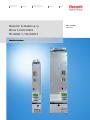
Rexroth IndraDrive C
Drive Controllers
HCS02.1, HCS03.1
Operating Instructions
Pneumatics
Service
R911314905
Edition 01
About this Documentation
Title
Rexroth IndraDrive
Rexroth IndraDrive C
Drive Controllers
HCS02.1, HCS03.1
Type of Documentation
Document Typecode
Internal File Reference
Purpose of Documentation
Record of Revisions
Copyright
Operating Instructions
DOK-INDRV*-FU*********-IB01-EN-P
Document Number, 120-2400-B327-01/EN; Mat. No.: R911314905
This documentation describes the mounting, installation, commissioning,
parameterization and troubleshooting of Rexroth IndraDrive controllers on
the basis of the power sections HCS02 or HCS03 and the control sections
BASIC OPENLOOP or BASIC PROFIBUS with comfort control panel.
Description
Release
Date
Notes
DOK-INDRV*-FU*********-IB01-EN-P
06-2006
First Release
Bosch Rexroth AG
2006
Copying this document, giving it to others and the use or communication
of the contents thereof without express authority, are forbidden. Offenders
are liable for the payment of damages. All rights are reserved in the event
of the grant of a patent or the registration of a utility model or design
(DIN 34-1).
Validity
Published by
The data specified above only serve to describe the product. No
statements concerning a certain condition or suitability for a certain
application can be derived from our information. The given information
does not release the user from the obligation of own judgement and
verification. It must be remembered that our products are subject to a
natural process of wear and aging.
Bosch Rexroth AG
Bgm.-Dr.-Nebel-Str. 2 • D-97816 Lohr a. Main
Telephone +49 (0)93 52/40-0 • Tx 68 94 21 • Fax +49 (0)93 52/40-48 85
http://www.boschrexroth.de/
Dept. EDY1 (RR/US/BB)
Note
This document has been printed on chlorine-free bleached paper.
DOK-INDRV*-FU*********-IB01-EN-P
Rexroth IndraDrive
Contents I
Contents
1
Introducing the Products
1.1
1-1
Introduction ................................................................................................................................... 1-1
Terms, Basic Principles ........................................................................................................... 1-1
1.2
Rexroth IndraDrive Hardware Platform ........................................................................................ 1-6
Drive Controllers ...................................................................................................................... 1-6
Motors and Measuring Systems .............................................................................................. 1-7
Master Communication............................................................................................................ 1-8
1.3
Rexroth IndraDrive Firmware Platform ......................................................................................... 1-8
Type Code ............................................................................................................................... 1-8
Functions Overview ................................................................................................................. 1-9
1.4
Rexroth IndraDyn Motors............................................................................................................ 1-12
Housing Motors...................................................................................................................... 1-12
Kit Motors............................................................................................................................... 1-12
1.5
Third-Party Motors at IndraDrive Controllers.............................................................................. 1-13
General Information on Third-Party Motors........................................................................... 1-13
Requirements on Third-Party Motors .................................................................................... 1-14
Requirements on the Encoder of the Third-Party Motor ....................................................... 1-17
Notes on Selection and Commissioning................................................................................ 1-17
1.6
Approval, Listing ......................................................................................................................... 1-18
Conformities........................................................................................................................... 1-18
C-UL-US-Listing..................................................................................................................... 1-18
2
Important Directions for Use
2.1
2-1
Appropriate Use............................................................................................................................ 2-1
Introduction .............................................................................................................................. 2-1
Areas of Use and Application .................................................................................................. 2-2
2.2
3
Inappropriate Use ......................................................................................................................... 2-2
Safety Instructions for Electric Drives and Controls
3.1
3-1
General Information ...................................................................................................................... 3-1
Using the Safety Instructions and Passing them on to Others................................................ 3-1
Instructions for Use.................................................................................................................. 3-1
Explanation of Warning Symbols and Degrees of Hazard Seriousness ................................. 3-3
Hazards by Improper Use........................................................................................................ 3-4
3.2
Instructions with Regard to Specific Dangers............................................................................... 3-5
Protection Against Contact with Electrical Parts ..................................................................... 3-5
Protection Against Electric Shock by Protective Low Voltage (PELV) .................................... 3-6
Protection Against Dangerous Movements ............................................................................. 3-7
DOK-INDRV*-FU*********-IB01-EN-P
II Contents
Rexroth IndraDrive
Protection Against Magnetic and Electromagnetic Fields During Operation and
Mounting .................................................................................................................................. 3-9
Protection Against Contact with Hot Parts ............................................................................ 3-10
Protection During Handling and Mounting............................................................................. 3-11
Battery Safety ........................................................................................................................ 3-11
Protection Against Pressurized Systems .............................................................................. 3-12
4
Identification, Transport, Storage, Installation Conditions
4.1
4-1
Identification.................................................................................................................................. 4-1
Type Code ............................................................................................................................... 4-1
Type Plates.............................................................................................................................. 4-4
4.2
Transport and Storage.................................................................................................................. 4-6
Transport of the Devices ......................................................................................................... 4-6
Storage of the Devices ............................................................................................................ 4-6
4.3
Installation Conditions................................................................................................................... 4-7
Ambient and Operating Conditions.......................................................................................... 4-7
Compatibility with Foreign Matters .......................................................................................... 4-9
5
Electrical Data
5.1
5-1
Power Sections ............................................................................................................................. 5-1
Type Current and Connected Load ......................................................................................... 5-1
Control Voltage Supply............................................................................................................ 5-2
Power Voltage Supply- Mains Connection .............................................................................. 5-3
Limited Length of Motor Power Cables ................................................................................... 5-4
5.2
Control Sections ........................................................................................................................... 5-6
Relay Contact Type 1 .............................................................................................................. 5-6
Relay Contact Type 2 .............................................................................................................. 5-6
Relay Contact Type 3 .............................................................................................................. 5-7
Digital Inputs/Outputs .............................................................................................................. 5-7
Analog Inputs/Outputs ............................................................................................................. 5-9
5.3
Additional Components............................................................................................................... 5-15
Mains Filter HNF.................................................................................................................... 5-15
Mains Filter (-Combination) HNK........................................................................................... 5-16
Mains Choke HNL01.1E (feeding)......................................................................................... 5-16
Mains Choke HNL01.1E-****-S (Current-Compensated) ...................................................... 5-17
Braking Resistor HLR ............................................................................................................ 5-17
Motor Filter HMF.................................................................................................................... 5-26
6
Mounting and Installation
6.1
6-1
Mounting ....................................................................................................................................... 6-1
Dimensions – Power Sections................................................................................................. 6-1
Dimensions – Mains Filter HNF............................................................................................... 6-7
Dimensions – Mains Choke HNL01.1E (infeeding) ................................................................. 6-9
Dimensions – Standard Braking Resistors HLR01.1............................................................. 6-12
Dimensions – Reinforced Braking Resistors HLR01.1.......................................................... 6-14
Dimensions – Motor Filter HMF............................................................................................. 6-17
Combination of Drive Controllers of the Rexroth IndraDrive C Product Range .................... 6-22
DOK-INDRV*-FU*********-IB01-EN-P
Rexroth IndraDrive
Contents III
Multiple-Line Arrangement of Drive Controllers .................................................................... 6-24
6.2
Electrical Installation ................................................................................................................... 6-25
Rules for Design of Installations with Drive Controllers in Compliance with EMC ................ 6-25
EMC-Optimal Installation in Facility and Control Cabinet...................................................... 6-26
Ground Connections.............................................................................................................. 6-32
Installing Signal Lines and Cables......................................................................................... 6-33
General Measures of Radio Interference Suppression for Relays, Contactors,
Switches, Chokes, Inductive Loads....................................................................................... 6-34
Installing the 24V Supply ....................................................................................................... 6-35
Connection Diagram .............................................................................................................. 6-36
Connections and Connectors ................................................................................................ 6-38
Accessories HAS ................................................................................................................... 6-67
7
Commissioning and Parameterization
7.1
7-1
Basics ........................................................................................................................................... 7-1
Control Panels ......................................................................................................................... 7-1
Parameters .............................................................................................................................. 7-1
Master Communication Interfaces........................................................................................... 7-3
Parameterization Mode / Operating Mode .............................................................................. 7-4
Default Settings in the Motor Encoder Data Memory ("Load Defaults Procedure") ................ 7-9
7.2
Parameterization......................................................................................................................... 7-12
Control Panels ....................................................................................................................... 7-12
Menu Structure ...................................................................................................................... 7-16
7.3
Overview of Parameters – Base Package.................................................................................. 7-36
S-0-0000 – S-0-0100 ............................................................................................................. 7-36
S-0-0101 – S-0-0200 ............................................................................................................. 7-41
S-0-0201 – S-0-0300 ............................................................................................................. 7-45
S-0-0301 – S-0-0400 ............................................................................................................. 7-47
S-0-0401 – S-0-1000 ............................................................................................................. 7-50
P-0-0001 – P-0-0689 (General Functions) ............................................................................ 7-51
P-0-0690 – P-0-0899 (Synchronization Mode)...................................................................... 7-85
P-0-1100 – P-0-1299 (Velocity Control) ................................................................................ 7-87
P-0-1500 – P-0-1599 (General Device Parameters) ............................................................. 7-96
P-0-2000 – P-0-2999 (General Device Parameters .............................................................. 7-96
P-0-3600 – P-0-4095 (General Device Parameters) ............................................................. 7-97
7.4
Basic Functions ........................................................................................................................ 7-108
Serial Communication ......................................................................................................... 7-108
Master Communication........................................................................................................ 7-110
Profile Types........................................................................................................................ 7-114
Motor Control ....................................................................................................................... 7-117
Scaling of Physical Data...................................................................................................... 7-118
7.5
Voltage-Controlled Operation (Open-Loop U/f Control) ........................................................... 7-121
Overview.............................................................................................................................. 7-121
Automatic Setting of Motor Control Parameters.................................................................. 7-122
7.6
Closed-Loop Axis Control (Closed-Loop Operation) ................................................................ 7-131
Automatic Setting of Axis Control ........................................................................................ 7-136
7.7
Positioning Block Mode ............................................................................................................ 7-137
DOK-INDRV*-FU*********-IB01-EN-P
IV Contents
8
Rexroth IndraDrive
Diagnostic and Service Functions
8.1
8-1
Diagnostic System ........................................................................................................................ 8-1
Diagnostic Status Messages ................................................................................................... 8-1
Diagnostic Command Messages............................................................................................. 8-1
Warnings.................................................................................................................................. 8-1
General Description of Error Messages and Error Reactions ................................................. 8-2
8.2
Recommended Actions for Operating States, Activities and Reactions of the Drive
Controller ...................................................................................................................................... 8-5
8.3
Troubleshooting .......................................................................................................................... 8-21
Check Drive Components...................................................................................................... 8-21
Replacing Devices ................................................................................................................. 8-21
Cables.................................................................................................................................... 8-23
Replacing the Firmware......................................................................................................... 8-24
Firmware Release Update..................................................................................................... 8-25
Firmware Version Upgrade.................................................................................................... 8-29
Possible Problems during Firmware Replacement ............................................................... 8-35
8.4
Service and Maintenance ........................................................................................................... 8-36
Deactivation ........................................................................................................................... 8-36
Dismantling ............................................................................................................................ 8-36
Disposal ................................................................................................................................. 8-37
Environmental Protection ...................................................................................................... 8-37
9
Service & Support
9-1
9.1
Helpdesk ....................................................................................................................................... 9-1
9.2
Service-Hotline ............................................................................................................................. 9-1
9.3
Internet.......................................................................................................................................... 9-1
9.4
Vor der Kontaktaufnahme... - Before contacting us... .................................................................. 9-1
9.5
Kundenbetreuungsstellen - Sales & Service Facilities ................................................................. 9-2
10 Index
10-1
DOK-INDRV*-FU*********-IB01-EN-P
Introducing the Products 1-1
Rexroth IndraDrive
1
Introducing the Products
1.1
Introduction
Terms, Basic Principles
Parameters
Communication between master and drive takes place, with a few
exceptions, by means of parameters.
Parameters are used for:
• determining the configuration
• parameterizing the control loop
• triggering and controlling drive functions and commands
• transmitting command values and actual values (according to
requirements, cyclically or acyclically)
All operating data are mapped to parameters!
The operating data stored in parameters can be identified by means of
the IDN. They can be read and transferred, if required. The user write
access to parameters depends on the properties of the respective
parameter and the current communication phase. Specific parameter
values (operating data) are checked for validity by the drive firmware.
Data Storage and Parameter Handling
Data Memory
Several non-volatile data memories are available in an IndraDrive device:
• in the controller
• in the motor encoder (depending on motor type)
In addition, a volatile data memory (working memory) is available in the
controller.
Condition As Supplied
Condition as supplied of the Rexroth drive components:
• The controller memory contains the drive firmware and the controllerspecific parameter values.
• The motor encoder memory contains the encoder-specific and,
depending on the motor type, the motor-specific parameter values.
Storing the Application-Specific
Parameter Values
Saving Parameter Values
The application-specific parameter values are stored in the controller. Due
to the limited number of writing cycles of non-volatile storage media,
application-specific parameter values can be stored in the working
memory (volatile memory), too.
Saving application-specific parameter values is required in the following
cases:
• after initial commissioning of the machine axis or the motor
• before replacing the controller for servicing (if possible)
Application-specific parameter values can be saved via:
• "IndraWorks D" commissioning tool → saving the parameter values on
external data carrier
• control master → saving the parameter values on master-side data
carrier
• comfort control panel
DOK-INDRV*-FU*********-IB01-EN-P
1-2 Introducing the Products
Parameter IDN Lists
Loading Parameter Values
Rexroth IndraDrive
The drive supports master-side saving of parameter values by listing
parameter identification numbers (IDNs). Using these lists guarantees
complete storage of the application-specific parameter values. It is also
possible to determine IDN lists defined by the customer.
Loading parameter values is required in the following cases:
• initial commissioning of the motor (loading basic parameter values and
motor-specific parameter values)
• serial commissioning of machine axes at series machines (loading the
values saved after initial commissioning)
• reestablishing a defined original status (repeated loading of the values
saved after initial commissioning)
• replacing the controller for servicing (loading the current parameter
values saved before servicing)
• Possibilities of loading parameter values to the controller:
• motor encoder data memory → loading the parameter values by
command or via the control panel during initial motor commissioning
• "IndraWorks D" commissioning tool → loading the parameter values
from external data carrier
• control master → loading the parameter values from master-side data
carrier
Checksum of Parameter Values
By means of checksum comparison, the control master can determine
whether the values of the application-specific parameter values currently
active in the drive correspond to the values saved on the master side.
Password
IndraDrive controllers provide the possibility to protect parameter values
against accidental or unauthorized change by means of a password. With
regard to write protection, there are 3 groups of parameters that can be
written:
• Parameters that are write-protected as a standard, such as motor
parameters, hardware code parameters, encoder parameters, error
memory etc. ("administration parameters"). The values of these
parameters guarantee correct function and performance of the drive.
• Parameters the customer can combine in groups and protect them
with a so-called customer password. This allows protecting parameter
values, that are used for adjusting the drive to the axis, after having
determined them.
• All other parameters that can be written and are not contained in the
above-mentioned groups. They are not write-protected.
Kinds of Passwords
The drive firmware allows activating and deactivating the write protection
for parameter values by means of three hierarchically different
passwords:
• Customer password
The parameter values of a parameter group combined by the
customer can be protected.
• Control password
Parameters protected by a customer password can be written;
"administration parameters" remain write-protected.
• Master password
All parameters that can be written, including "administration
parameters" and parameters protected by a customer password, can
be changed.
DOK-INDRV*-FU*********-IB01-EN-P
Introducing the Products 1-3
Rexroth IndraDrive
Commands
Commands are used to activate and control complex functions or
monitoring features in the drive. The higher-level master can start,
interrupt or clear commands.
Each command is assigned to a parameter by means of which the
execution of the command can be controlled. During the execution of the
command the display of the control panel reads "Cx", "C" representing the
diagnostic command message and "x" representing the number of the
command.
Note:
Each command that was started must be actively cleared
again.
All commands available in the drive are stored in the S-0-0025, IDN-list
of all procedure commands parameter.
Kinds of Commands
There are 3 different kinds of commands:
• Drive control commands
• can cause automatic drive motion,
• can be started only when drive enable has been set,
• deactivate the active operating mode during its execution.
• Monitoring commands
• activate or deactivate monitors or functions in the drive.
• Administration commands
• carry out administration tasks,
• cannot be interrupted.
See also "Command Processing" in chapter "Master Communication"
Operating Modes
The selection of operating modes defines which command values will be
processed in which way, in order to lead to the desired drive motion. The
operating mode does not determine how these command values are
transmitted from the master to the slave.
One of the four or eight (for SERCOS) operating modes defined in
parameters is always active when the following conditions have been
fulfilled:
• control section and power section are ready for operation
• drive enable signal sees a positive edge
• drive follows command value
• "Drive Halt" function has not been activated
• no drive control command is active
• no error reaction is carried out
The display of the control panel reads "AF" when an operating mode was
activated.
Note:
All implemented operating modes are stored in the S-0-0292,
List of all operating modes parameter.
See also chapter "Operating Modes"
DOK-INDRV*-FU*********-IB01-EN-P
1-4 Introducing the Products
Rexroth IndraDrive
Warnings
Depending on the active operating mode and the parameter settings,
many monitoring functions are carried out. If a status is detected that still
allows correct operation but in case this status persists will cause an error
to occur and therefore cause the drive to be automatically switched off,
the drive firmware generates a warning message.
Note:
Warning Classes
Warnings do not cause automatic shutdown (exception: fatal
warning).
Warnings are classified in different warning classes which determine
whether the drive, when the warning is generated, carries out an
automatic reaction or not.
Note:
The warning class can be recognized by the diagnostic
message.
The following classes of warnings are distinguished:
• without drive reaction → diagn. message no. E2xxx, E3xxx, E4xxx
• with drive reaction
Note:
→ diagn. message no. E8xxx
Warnings cannot be cleared. They persist until the condition
that activated the warning is no longer fulfilled.
Errors
Depending on the active operating mode and the parameter settings,
many monitoring functions are carried out. If a status is detected that
affects or prevents correct operation the drive firmware generates an
error message.
Error Classes
Errors are classified in different error classes. There are 6 error classes
with different drive error reactions.
Note:
The error class can be recognized by the diagnostic message
number.
Diagnostic message
number
Error class
F2xxx
non-fatal error
F3xxx
non-fatal safety technology error
F4xxx
interface error
F6xxx
travel range error
F7xxx
safety technology error
F8xxx
fatal error
F9xxx
fatal system error
E-xxxx
fatal system error "processor exception"
Fig. 1-1:
Overview of error classes
Note:
Apart from the mentioned error classes that can occur during
operation, errors can occur when the devices are booted and
DOK-INDRV*-FU*********-IB01-EN-P
Introducing the Products 1-5
Rexroth IndraDrive
during firmware download. These errors are not displayed at
the control panel with a diagnostic message number of the
"Fxxxx" pattern, but with a short text. Boot errors and firmware
download errors are separately described in the
documentation "Troubleshooting Guide" (diagnostic message
description).
Error Reactions of the Drive
If the drive controller is in control and an error status is detected, the
execution of a drive error reaction is automatically started. The diagnostic
message number "Fxxxx" flashes on the display of the control panel.
The drive reaction in the case of interface errors and non-fatal errors is
determined in parameter P-0-0119, Best possible deceleration At the
end of each error reaction, the drive is torque-free.
See also "Error Reactions" in chapter "Drive Functions"
Clearing Error Messages
Error messages are not cleared automatically but by the following action:
• activating the S-0-0099, C0500 Reset class 1 diagnostics command
- or • actuating the "Esc" button on the control panel
If the error status persists the error message is immediately generated
again.
Clearing Error Messages when
Drive Enable Was Set
If a drive error occurs while operating with drive enable having been set,
the drive carries out an error reaction. The drive automatically deactivates
itself at the end of each error reaction; in other words, the output stage is
switched off and the drive switches from an energized to a de-energized
state.
To reactivate the drive:
• clear the error message and
• input a positive edge for drive enable again.
Error Memory
The diagnostic message numbers of occurring errors are written to an
error memory. This memory contains the diagnostic message numbers of
the last 50 errors that occurred and the time when they occurred. Errors
caused by a shutdown of the control voltage (e.g. F8070 +24Volt DC
error) are not stored in the error memory.
The diagnostic message numbers in the error memory are mapped to the
P-0-0192, Diagnostic numbers of error memory parameter and can be
displayed by means of the control panel. By means of the "IndraWorks D"
commissioning tool it is possible to display the diagnostic message
numbers and the respective times at which the errors occurred.
DOK-INDRV*-FU*********-IB01-EN-P
1-6 Introducing the Products
1.2
Rexroth IndraDrive
Rexroth IndraDrive Hardware Platform
Drive Controllers
Overview
The drive controller consists of two essential parts:
Power section
Control section
•
power section
•
control section
The power section incorporates the control section and has the following
connections:
•
mains voltage connection (at supply modules and HCS devices)
•
motor connection (with optional motor holding brake and motor
temperature monitor)
•
24 V control voltage
•
DC bus connection
•
module bus connection
•
connection for external braking resistor (at HCS devices)
The control section is a separate component that is plugged into the
power section. The drive controller is supplied complete with factoryinstalled (possibly configured) control section.
Power Sections
IndraDrive C
300 mm Design
• HCS02.1E-W0012
• HCS02.1E-W0028
• HCS02.1E-W0054
• HCS02.1E-W0070
400 mm Design
• HCS03.1E-W0070
• HCS03.1E-W0100
• HCS03.1E-W0150
• HCS03.1E-W0210
Control Sections
• BASIC OPENLOOP (single axis; type CSB01.1N-FC-…)
• BASIC PROFIBUS (single axis CSB01.1N-PB-…)
Supported Control Section Configurations
The configurable control sections differ with regard to the scope of their
configurability. It basically depends on the control section type and the
corresponding firmware variant. The following abbreviations are used:
Options for master communication:
• PB
→ PROFIBUS-DP
• FC
→ FC Interface
DOK-INDRV*-FU*********-IB01-EN-P
Introducing the Products 1-7
Rexroth IndraDrive
Motors and Measuring Systems
Supported Motors
The table below contains an overview of the Rexroth motors which can be
operated at IndraDrive controllers.
Housing motors
synchronous
MHD
2AD
MKD
ADF
MKE
MAD (IndraDyn A)
MSK (IndraDyn S) MAF (IndraDyn A)
MAL
SF (Bosch)
Fig. 1-2:
Third party motors
Kit motors
asynchronous
synchronous
asynchr.
MLF (IndraDyn L)
MBS (Standard)
MBSxx2 (IndraDyn H)
MBT (IndraDyn T)
LSF
1MB
Appropriate Rexroth motors for IndraDrive
Third party motors must meet the specified requirements.
Supported Measuring Systems
Motor Encoders and External
Optional Encoders
In addition to the encoders integrated in the Rexroth motors, the
IndraDrive firmware can evaluate the following measuring systems as
motor encoders or as external optional control encoders:
• Bosch Rexroth GDS or GDM encoders (single-turn or multi-turn type)
• resolvers according to Rexroth signal specification (single-turn or
multi-turn type)
• encoders with sine signals and EnDat2.1 interface (1 Vpp)
• encoders with sine signals (1 Vpp)
• encoders with square-wave signals (TTL)
• Hall sensor box and encoder with sine signals (1 Vpp)
• Hall sensor box and encoder with square-wave signals (TTL)
• encoders with sine signals and HIPERFACE interface (1 Vpp)
Measuring Encoders
For measuring purposes the firmware can evaluate the following
measuring systems (measuring encoders, no control encoders):
• Bosch Rexroth GDS or GDM encoders (single-turn or multi-turn type)
• encoders with sine signals and EnDat2.1 interface (1 Vpp)
• encoders with sine signals (1 Vpp)
• encoders with square-wave signals (TTL)
• encoders with sine signals and HIPERFACE interface (1 Vpp)
• motor encoders of MSK, MHD, 2AD, ADF, MAD, MAF motors
• SSI encoders
Note:
DOK-INDRV*-FU*********-IB01-EN-P
Resolvers cannot be evaluated as measuring encoders!
1-8 Introducing the Products
Rexroth IndraDrive
Master Communication
PROFIBUS Interface
General Features
• cyclic data exchange of command and actual value (max. 32 byte
each direction; min. cycle time of 500 µs)
• parameter channel for parameterization and diagnosing via field bus
• safe process data channel (PROFIsafe), optional
• free configuration of telegram contents possible (many cyclic
configurable parameter IDN)
1.3
Rexroth IndraDrive Firmware Platform
Type Code
Fig. 1-3:
Alternative
expansion
packages
Additive
expansion
packages
VRS-
D5-
x-
xxx-
xx
Basic structure of the firmware type designation
Language
Open/closedloop
Alternative
functional
packages
IndraMotion
MLD-S
The following overview shows the available scope of functions of the
respective base package:
Release
Basic
single-axis
04
Version
Control
section
-MPB-
Base
package
Firmware Types That Can Be
Ordered
Open-/closedloop
FWA-INDRV*
Language
Basic single-axis
Release
IndraDrive-Firmware
Version
The individual functional packages can be combined to form the following
firmware types that can be ordered:
Base package of
variant …
(depending on
control section)
Structure of the Firmware Type
Designation
Scope of functional packages
FWA-INDRV*-
MPB-
04
VRS-
D5-
0-
NNN
-NN
base package (open-loop)
FWA-INDRV*-
MPB-
04
VRS-
D5-
0-
SNC
-NN
base package (open-loop) + synchronization
FWA-INDRV*-
MPB-
04
VRS-
D5-
0-
MSP
-NN
base package (open-loop) + main spindle
FWA-INDRV*-
MPB-
04
VRS-
D5-
0-
ALL
-NN
base package (open-loop) + all altern. functions
FWA-INDRV*-
MPB-
04
VRS-
D5-
0-
NNN
-ML
base package (open-loop) + IndraMotion MLD-S
FWA-INDRV*-
MPB-
04
VRS-
D5-
0-
***
-ML
base package (open-loop) + *** + IndraMotion MLD-S
FWA-INDRV*-
MPB-
04
VRS-
D5-
1-
NNN
-NN
base package (closed-loop)
FWA-INDRV*-
MPB-
04
VRS-
D5-
1-
SRV
-NN
base package (closed-loop) + servo function
FWA-INDRV*-
MPB-
04
VRS-
D5-
1-
SNC
-NN
base package (closed-loop) + synchronization
FWA-INDRV*-
MPB-
04
VRS-
D5-
1-
MSP
-NN
base package (closed-loop) + main spindle
FWA-INDRV*-
MPB-
04
VRS-
D5-
1-
ALL
-NN
base package (closed-loop) + all altern. functions
FWA-INDRV*-
MPB-
04
VRS-
D5-
1-
NNN
-ML
base package (closed-loop) + IndraMotion MLD-S
FWA-INDRV*-
MPB-
04
VRS-
D5-
1-
***
-ML
base package (closed-loop) + *** + IndraMotion MLD-S
Firmware
range
***
Fig. 1-4:
selected option "alternative functional packages" according to
availability
Overview of firmware types and functional packages they are
containing
DOK-INDRV*-FU*********-IB01-EN-P
Introducing the Products 1-9
Rexroth IndraDrive
Functions Overview
Supported Operating Modes
The drive firmware supports the following operating modes:
• torque/force control
• velocity control
• position control with cyclic command value input
• drive-internal interpolation
• drive-controlled positioning
• positioning block mode
• synchronization modes:
• velocity synchronization with real/virtual master axis
• phase synchronization with real/virtual master axis
• electronic cam shaft with real/virtual master axis
• electronic motion profile with real/virtual master axis
Note:
The operating modes supported by the firmware depend on
the hardware and firmware and are contained in parameter
S-0-0292, List of all operating modes.
Drive Functions
These are the most important drive functions of the MPX-04 firmware:
• Drive Halt
• establishing the position data reference
• drive-controlled homing
• setting absolute measuring
• shifting the position data reference
• drive error reactions
• best possible deceleration
• package reaction on error
• NC reaction on error
• E-Stop function
• compensation functions/corrections
• friction torque compensation
• encoder correction
• axis error correction
• quadrant error correction
• spindle positioning
• drive-integrated command value generator
• parameter set switching
• probe function
• encoder emulation
• programmable position switch
• drive-integrated PLC (IndraMotion MLD-S)
• integrated safety technology
DOK-INDRV*-FU*********-IB01-EN-P
1-10 Introducing the Products
Rexroth IndraDrive
• monitoring functions
• limitations that can be parameterized
• output of control signals
• numerous diagnostic possibilities
• drive-internal generation of diagnostic messages
• analog output
• status displays, status classes
• oscilloscope function
• monitoring function
• patch function
• code of optional card
• parameter value check
• operating hours counter, logbook function, error memory
Performance Data
Overview
For the control performance of the IndraDrive range we basically
distinguish three levels with regard to the clock rates (cycle times):
• Basic performance
→ standard control performance by medium internal clock rates for the
control loops and the signal processing of inputs/outputs or driveintegrated PLC (IndraMotion MLD-S)
In this documentation the clock rate data refer to the following
characteristic values:
• current loop clock
TA_current
• velocity loop clock
TA_velocity
• position loop clock
TA_position
• cycle time of PLC (IndraMotion MLD-S)
TMLD-S
• cycle time of master communication
TMastCom
The table below contains an overview of the clock rates depending on the
respective control performance. The detailed assignment of the clock rate
to control section design, performance level and parameter setting is
contained in the table in section "Control Section Design and
Performance" (see below).
Performance
Basic
Fig. 1-5:
Control
section type/
firmware
CSB01.1/MPB
Functional
packages
all, except for
"synchronization" and
"IndraMotion"
Perform.
level
Basic
Basic
TA_Strom
TA_Geschw
TA_Lage
62,5/83,3/125 µs
250 µs
500 µs
TMLD-S
TFKM
2000 µs 500/1000 µs
Clock rates (depending on the available performance)
TA_current
TA_velocity
TA_posit.
TMLD-S
TMastCom
Switching
frequency 1)
P-0-0556
bit 2 bit 5
125 µs
250 µs
500 µs
--
1000 µs
4000 Hz
0
0
125 µs
250 µs
500 µs
--
1000 µs
8000 Hz
0
0
1)
:
can be set via P-0-0001
P-0-0556:
config word of axis controller
Fig. 1-6:
Performance depending on the control section design
DOK-INDRV*-FU*********-IB01-EN-P
Introducing the Products 1-11
Rexroth IndraDrive
Selecting Performance via
Parameter P-0-0556
For certain applications it is necessary to use the same clock rates in all
axes so that the slowest drive sets the clock. It is therefore possible to
specifically reduce the performance via bit 2 and bit 5 of parameter
P-0-0556, Config word of axis controller.
• For BASIC control sections it is possible to select the performance
levels "Basic" or "Economy" via bit 5 of P-0-0556.
See also Parameter Description "P-0-0556, Config word of axis controller"
Note:
Restricted Performance with
Certain Functional Packages
The effective clock rates of the active performance level are
contained in the table "Performance depending on the control
section design" in section "Control Section Design and
Performance" (see above).
If you use extensive and complex functions, the internal clock rates for
BASIC control sections (CSB with firmware MPB and CDB with
firmware MPD) are automatically reduced. This applies to the use of the
following functional packages:
• drive-integrated PLC "IndraMotion MLD-S" (functional package "ML")
• expansion package "synchronization" (functional package "SNC")
If you use one of these functional packages for BASIC control sections,
the clock rates (position loop, velocity loop) are reduced to the lowest
performance level "Economy!"
DOK-INDRV*-FU*********-IB01-EN-P
1-12 Introducing the Products
1.4
Rexroth IndraDrive
Rexroth IndraDyn Motors
Housing Motors
Type Code S
Motor size
Motor length
Windings code
Housing design
Encoder
Electrical
Connection
Shaft
Holding brake
Other design
MSK030B-0900-NN-S1-UG0-NNNN
Product
Example
MSK
030
B
0900
NN
S1
U
G
0
NNNN
Fig. 1-7:
Basic structure of type code
Type Code IndraDyn A
Motor size
Motor length
Windings code
Cooling mode
Encoder
Electrical Connection
Shaft
Holding brake
Mounting style
Bearings
Vibration severity
grade
MAF130B-0150-FQ-M0-LH0-05-N1
Product
Example
MAF
130
B
0150
FQ
M0
L
H
0
05
N
1
Fig. 1-8:
Basic structure of type code
Kit Motors
Type Code IndraDyn L
Motor size
Motor length
Windings code
Cooling mode
Encapsulation
Encoder
Electrical
Connection
Other design
MLP100A-0120-FS-N0CN-NNNN
Product
Example
MLP
100
A
0120
F
S
N0
CN
NNNN
Fig. 1-9:
Basic structure of type code
DOK-INDRV*-FU*********-IB01-EN-P
Introducing the Products 1-13
Rexroth IndraDrive
Type Code IndraDyn H
Motor size
Motor length
Mounting style
Internal diameter
of the rotor
Other design
MRS102B-1N-0046-NNNN
Product
Example 1
MRS
102
B
1N
0046
NNNN
Fig. 1-10:
Motor size
Motor length
Windings code
Cooling mode
Cooling
connector
Encoder
Electrical
connection
Other design
MSS102B-0800-FA-N0CN-NNNN
Product
Example 2
Basic structure of type code
MSS
102
B
0800
F
A
N0
CN
NNNN
Fig. 1-11:
1.5
Basic structure of type code
Third-Party Motors at IndraDrive Controllers
General Information on Third-Party Motors
Why Use Third-Party Motors at IndraDrive?
Today machine axes are mainly moved with electric drives. Motors of
standard design are used in most cases as this is the most cost-efficient
solution.
Special Requirements
Due to special requirements at machine axes, constructional or safetyrelated aspects, it may be necessary for the machine manufacturer to use
a motor construction diverging from the standard.
Undeliverable Motor Design
For these cases there is the demand on the drive supplier to realize, apart
from the deliverable standard drive consisting of (standard) motor,
controller, cable and, if required, machine control unit, drives with motors
that are not included in his own product range due to the special design.
Check Before Using Third-Party
Motors
At Rexroth controllers of the IndraDrive range it is also possible to use
third-party motors. For this purpose, check whether the third-party motor
complies with the requirements of use.
Which are the Important Directives?
Additional Aspects to be
Observed
According to the legal requirements
• of the EU directives EMC89/336/EEC and
• the German EMC laws
installations and machines have to be designed and built according to the
present state of standardization. In order to comply with the machine
directives regarding "electromagnetic compatibility (EMC)", a conformity
test of the drive system (motor with controller and connection design) has
DOK-INDRV*-FU*********-IB01-EN-P
1-14 Introducing the Products
Rexroth IndraDrive
to be carried out. The test of the drive system and compliance with the
directives have to be guaranteed by the machine manufacturer.
Third-Party Motors to be Controlled
Motor Types
The following motor types can be controlled:
• asynchronous motors, rotary
• asynchronous motors, linear
• synchronous motors, rotary
• synchronous motors, linear
These motors can be operated within the scope of the technical data of
the selected IndraDrive controller. If motors have been provided with a
holding brake, it should be controlled via the controller. Make sure that the
relevant technical data of the motor holding brake are complying with
those of the holding brake output.
Note:
Synchronous Motors
For third-party motors Bosch Rexroth, as a matter of principle,
does not assume the guarantee for the power data at the
motor shaft!
In the case of synchronous motors, the commutation offset has to be set
during commissioning. The drive firmware provides several methods for
determining this offset so that it is possible to determine the value for
different motor characteristics.
Note:
Observe the restrictions in conjunction with the commutation
offset determination when using synchronous motors!
See Functional Description of firmware "Motor Control:
Commutation Setting" in chapter "Drive Control"
Possibly available reluctance property cannot be used for synchronous
third-party motors! For third-party motors it is impossible to determine failsafe motor parameter values for using the reluctance property; the
respective bit of P-0-4014, Type of construction of motor therefore
mustn't be set!
Requirements on Third-Party Motors
For successful and fail-safe use of a third-party motor check
• whether the third-party motor to be controlled satisfies the voltage
loads,
• which controller, including supply, is suitable due to the motor power to
be delivered,
• whether the third-party motor has the required minimum inductance,
• whether the motor can be protected against inadmissible temperature
rise in the case of overload (temperature evaluation),
• whether the mounted position measuring system can be evaluated by
the controller or which position measuring system can be selected for
kit motors.
Voltage Load of the Third-Party Motor
The voltage load of the insulation system of a motor occurring in practical
application is mainly influenced by the following characteristics:
• The output variables of the drive controller which is used (feed the
transmission distance).
DOK-INDRV*-FU*********-IB01-EN-P
Introducing the Products 1-15
Rexroth IndraDrive
• The cable parameters depending on cable design and length
(determine the properties of the transmission distance, such as the
attenuation).
• The motor design regarding capacitive and inductive properties (form
the end of the transmission distance).
As a result of the variables, the insulation system of the third-party motor,
as regards voltage, is loaded by the values
• peak voltage Upp and
• voltage change dv/dt.
The occurring peak voltages at the motor are caused by reflections in the
motor cable. The insulation of the motor is thereby loaded with other peak
voltages and voltage changes than the ones occurring at the output of the
power section.
Note:
Use of Voltage-Reducing
Components, Motor Filter HMF
Determine the occurring voltage load at the terminals of the
third-party motor in the application with all involved
components.
Use voltage-reducing components (e.g. motor filter HMF), if one of the
following criteria applies:
• allowed voltage change (dv/dt) of third-party motor smaller than
5 kV/µs
• allowed peak voltage (crest value) of third-party motor between phasephase and phase-housing smaller than 1500 V
• motor cable length smaller than 25 m
• mains voltage greater than AC440V
Note:
Apart from the nominal current IN, especially take the
maximum allowed switching frequency of the power output
stage (fs) into account with which the motor filter HMF may be
operated.
Verify the success of the voltage-reducing measure.
Minimum Inductance of Third-Party Motor
Depending on the controller used, the motor has to have a minimum
value for inductance. The actually available inductance of a motor can be
measured directly between two motor terminals by means of an
inductance measuring bridge. The measurement has to be made for a
complete motor wired for normal operation but not yet connected. During
the measurement one motor terminal remains open!
For asynchronous motors the measured value can only be used if the
rotor doesn't have closed slots!
Controller type
HCS with 3*AC230V
LU-V = 60* 4/(√2 * ITyp * fs) (in mH)
HMS, HMD at HMV (3*AC400V)
HMS, HMD at HCS (3*AC400V)
LU-V = 80* 4/(√2 * ITyp * fs) (in mH)
HMS, HMD at HMV (3*AC480V)
HMS, HMD at HCS (3*AC480V)
LU-V = 116* 4/( √2 * ITyp * fs) (in mH)
ITyp:
fs:
Fig. 1-12:
DOK-INDRV*-FU*********-IB01-EN-P
Minimum required motor inductance
maximum controller current acc. to type code (rms value)
desired switching frequency in kHz
Minimum inductances depending on controller data, supply units and
supply voltage
1-16 Introducing the Products
Rexroth IndraDrive
Use a three-phase choke in the motor feed wire, if the inductance of the
third-party motor is smaller than indicated in the table above. This choke
has to increase the inductance that can be measured between two motor
terminals to the minimum value.
Note:
When the inductance is measured, different inductance values
can be determined at different rotor positions within one pole
pair distance of the motor. The average value is relevant for
the check of the minimum value.
Correct values can only be determined when the motor is in
standstill!
Available third-party motor
LU-Vmin
LU-V
U
V
W
Motor
3x LDr
LDr = 0,5 * (LU-Vmin - LU-V)
(inductance measurement with 1 kHz)
Planned third-party motor
Calculating the leakage inductance
(asynchronous motor) or inductance
(synchronous motor) of the third-party
motor by means of the single-phase
equivalent circuit diagram
(manufacturer's specification!).
Determine choke by means of
calculation, if necessary.
It is recommended to contact Rexroth!
mounting of 3x LDr (three-phase choke)
Requirements on the choke:
- In_Dr ≥ In_Mot
The rated current of the choke has to be greater than or equal to
the rated motor current.
- Depending on the maximum speed, the choke is loaded with the respective
output frequency and the PWM frequency of the controller.
- The insulation class has to correspond at least to that of the motor or
has to be dimensioned for higher temperatures.
- The voltage load of the choke depends on the controller used.
Fig. 1-13: Data for possibly required choke
Temperature Evaluation of Third-Party Motor
Only operate such motors with incorporated temperature sensor at
IndraDrive controllers so that the motor can be thermally monitored by the
controller and protected against destruction by too high temperature rise
(see P-0-0512, Temperature sensor).
When, in exceptional cases, you want to operate third-party motors
without temperature sensor at IndraDrive controllers, you must determine
the thermal time constants of motor housing (P-0-4035) and motor
winding (P-0-4034, P-0-4037). The firmware-internal motor temperature
model can thereby reflect the cooling situation of the motor correctly.
Note:
In case the motor housing or blower is dirty, this worsens the
cooling situation of the motor and protection against thermal
overload is therefore insufficient!
DOK-INDRV*-FU*********-IB01-EN-P
Introducing the Products 1-17
Rexroth IndraDrive
Requirements on the Encoder of the Third-Party Motor
Motor Encoder of Asynchronous Third-Party Motor
Asynchronous motors can also be controlled by IndraDrive controllers in
"open-loop" operation (without motor encoder). In "closed-loop" operation
(with motor encoder) a relative measuring system is sufficient for
asynchronous motors.
Motor Encoder of Synchronous Third-Party Motor
For fail-safe drives with synchronous third-party motors at IndraDrive
controllers the following possible combinations or restrictions have to be
taken into account when selecting the measuring system:
Drive range
Motor measuring system
Synchronous thirdparty motor
absolute
+
relative
o
IndraDrive
+…
o…
advantageous combination
Combination is possible (restrictions specific to application),
commissioning may be more complicated!
Fig. 1-14: Possible combinations of synchronous third-party motor and motor
measuring system
Note:
The control section integrated in the controller can evaluate
measuring systems as a motor encoder if they are contained
in P-0-0074, Encoder type 1 (motor encoder) (see also
Project Planning Manual of the IndraDrive control sections).
For information on absolute and relative measuring systems
see section "Measuring Systems" of Functional Description of
firmware!
Notes on Selection and Commissioning
Selecting the Controller as Regards Continuous Current
The controller required for the respective motor and the supply unit are
determined by comparing the motor data to the data of these devices (see
documentation for HMS/HMD and HMV or HCS).
Note:
The continuous current of the controller should be greater than
that of the motor, the continuous power of the supply must be
greater than the sum of all average powers of the axes of the
drive system!
Selecting the Connection Technique
The available power and encoder cables are described in the
documentation "Connection Cables; Selection Data" (DOK-CONNECCABLE*STAND-AU...).
Notes on Commissioning
Note:
DOK-INDRV*-FU*********-IB01-EN-P
For further information, notes on commissioning and
supporting documents (e.g. forms for entering the required
data) see Functional Description of firmware.
1-18 Introducing the Products
1.6
Rexroth IndraDrive
Approval, Listing
Conformities
Declaration of Conformity
For Rexroth IndraDrive components there are declarations of conformity
available. These declarations confirm that the components are designed
according to valid EC directives. If required, you can ask your sales
representative for these declarations.
Low-Voltage Directive
The Rexroth products of a drive system mentioned in this documentation
comply with the requirements of the EC Directive 73/23/EEC (LowVoltage Directive), annex III B.
EMC Directive
The Rexroth products of a drive system mentioned in this documentation
comply with the requirements of the EC Directive 89/336/EEC (EMC
Directive) with the amendments 91/263/EEC and 93/68/EEC.
CE Label
CEf1.fh7
Fig. 1-15:
CE label
C-UL-US-Listing
Devices approved by the UL agency carry the following label:
Fig. 1-16:
C-UL-US label
DOK-INDRV*-FU*********-IB01-EN-P
Introducing the Products 1-19
Rexroth IndraDrive
Motors approved by the UL agency carry the following label:
C-UL-US Listed Components
Fig. 1-17:
C-UR-US label
Product
Component
HMS01.1N-
W0020, W0036, W0054, W0070, W0150, E 134201
W0210
HMS02.1N-
W0028, W0054
E 134201
HMD01.1N-
W0012, W0020, W0036
E 134201
HCS02.1E-
W0012, W0028, W0054, W0070
E 134201
HCS03.1E-
W0070, W0100, W0150, W0210
Manufacturer REFU
E254781
HMV01.1E-
W0030-A-07, W0075-A-07, W0120-A-07
E 134201
HMV01.1R-
W0018-A-07, W0045-A-07, W0065-A-07
E 134201
HMV02.1R-
W0015
E 134201
HLB01.1C-
01K0-N06R0-A-007-NNN
E 134201
HLB01.1D-
02K0-N03R4-A-007-NNN
E 134201
HLC01.1C-
01M0-A-007, 02M4-A-007
E 134201
HLC01.1D-
05M0-A-007
E 134201
NFD03.1-
-007, -016, -030, -055, -075, -130, -180
E 172117 and CSA
Cert. 1038841Master
Contr. 171321
HNL01.1-
.....
CSA Cert.
1492099Master
Contr. 222887
HNF01.1
In preparation
E 134201
HNK01.1
In preparation
E 134201
HLR01.1
In preparation
E 134201
Fig 1-18:
Note:
File Number
C-UL-US listed Rexroth IndraDrive components
The components are listed by the file number of „Underwriters
Laboratories Inc.®" (UL). The documented evidence of listing
can be seen in the internet: http://www.ul.com, "Certifications",
enter file number or "Company name: Rexroth.
The control sections are included in the listing of the power
sections. The control sections are not listed separately.
DOK-INDRV*-FU*********-IB01-EN-P
1-20 Introducing the Products
Rexroth IndraDrive
DOK-INDRV*-FU*********-IB01-EN-P
Important Directions for Use 2-1
Rexroth IndraDrive
2
Important Directions for Use
2.1
Appropriate Use
Introduction
Rexroth products represent state-of-the-art developments and
manufacturing. They are tested prior to delivery to ensure operating safety
and reliability.
The products may only be used in the manner that is defined as
appropriate. If they are used in an inappropriate manner, then situations
can develop that may lead to property damage or injury to personnel.
Note:
Rexroth as manufacturer is not liable for any damages
resulting from inappropriate use. In such cases, the guarantee
and the right to payment of damages resulting from
inappropriate use are forfeited. The user alone carries all
responsibility of the risks.
Before using Rexroth products, make sure that all the pre-requisites for
an appropriate use of the products are satisfied:
• Personnel that in any way, shape or form uses our products must first
read and understand the relevant safety instructions and be familiar
with appropriate use.
• If the products take the form of hardware, then they must remain in
their original state, in other words, no structural changes are permitted.
It is not permitted to decompile software products or alter source
codes.
• Do not mount damaged or faulty products or use them in operation.
• Make sure that the products have been installed in the manner
described in the relevant documentation.
DOK-INDRV*-FU*********-IB01-EN-P
2-2 Important Directions for Use
Rexroth IndraDrive
Areas of Use and Application
Drive controllers made by Bosch Rexroth are designed to control
electrical motors and monitor their operation.
Control and monitoring of the motors may require additional sensors and
actors.
Note:
The drive controllers may only be used with the accessories
and parts specified in this document. If a component has not
been specifically named, then it may not be either mounted or
connected. The same applies to cables and lines.
Operation is only permitted in the specified configurations and
combinations of components using the software and firmware
as specified in the relevant Functional Descriptions.
Every drive controller has to be programmed before commissioning,
making it possible for the motor to execute the specific functions of an
application.
The drive controllers have been developed for use in single- and multiaxis drive and control tasks.
To ensure an application-specific use, the drive controllers are available
with different drive power and different interfaces.
Typical applications of the drive controllers include:
• handling and mounting systems,
• packaging and food machines,
• printing and paper processing machines and
• machine tools.
The drive controllers may only be operated under the assembly and
installation conditions described in this documentation, in the specified
position of normal use and under the ambient conditions as described
(temperature, degree of protection, humidity, EMC, etc.).
2.2
Inappropriate Use
Using the drive controllers outside of the operating conditions described in
this documentation and outside of the indicated technical data and
specifications is defined as "inappropriate use".
Drive controllers must not be used, if
• ... they are subject to operating conditions that do not meet the
specified ambient conditions. This includes, for example, operation
under water, under extreme temperature fluctuations or extremely high
maximum temperatures.
• Furthermore, the drive controllers must not be used in applications
which have not been expressly authorized by Rexroth.
• Please carefully follow the specifications outlined in the general Safety
Instructions!
DOK-INDRV*-FU*********-IB01-EN-P
Safety Instructions for Electric Drives and Controls 3-1
Rexroth IndraDrive
3
Safety Instructions for Electric Drives and Controls
3.1
General Information
Using the Safety Instructions and Passing them on to Others
Do not attempt to install or commission this device without first reading all
documentation provided with the product. Read and understand these
safety instructions and all user documentation prior to working with the
device. If you do not have the user documentation for the device, contact
your responsible Bosch Rexroth sales representative. Ask for these
documents to be sent immediately to the person or persons responsible
for the safe operation of the device.
If the device is resold, rented and/or passed on to others in any other
form, then these safety instructions must be delivered with the device.
WARNING
Improper use of these devices, failure to follow
the safety instructions in this document or
tampering with the product, including disabling
of safety devices, may result in material
damage, bodily harm, electric shock or even
death!
Instructions for Use
Read these instructions before the initial startup of the equipment in order
to eliminate the risk of bodily harm or material damage. Follow these
safety instructions at all times.
• Bosch Rexroth AG is not liable for damages resulting from failure to
observe the warnings provided in this documentation.
• Read the operating, maintenance and safety instructions in your
language before starting up the machine. If you find that you cannot
completely understand the documentation for your product, please ask
your supplier to clarify.
• Proper and correct transport, storage, assembly and installation as
well as care in operation and maintenance are prerequisites for
optimal and safe operation of this device.
• Only assign trained and qualified persons to work with electrical
installations:
Only persons who are trained and qualified for the use and
operation of the device may work on this device or within its
proximity. The persons are qualified if they have sufficient
knowledge of the assembly, installation and operation of the
equipment as well as an understanding of all warnings and
precautionary measures noted in these instructions.
Furthermore, they must be trained, instructed and qualified to
switch electrical circuits and devices on and off in accordance
with technical safety regulations, to ground them and to mark
them according to the requirements of safe work practices.
They must have adequate safety equipment and be trained in
first aid.
• Only use spare parts and accessories approved by the manufacturer.
• Follow all safety regulations and requirements for the specific
application as practiced in the country of use.
DOK-INDRV*-FU*********-IB01-EN-P
3-2 Safety Instructions for Electric Drives and Controls
Rexroth IndraDrive
• The devices have been designed for installation in industrial
machinery.
• The ambient conditions given in the product documentation must be
observed.
• Only use safety-relevant applications that are clearly and explicitly
approved in the Project Planning Manual. If this is not the case, they
are excluded.
Safety-relevant are all such applications which can cause danger to
persons and material damage.
• The information given in the documentation of the product with regard
to the use of the delivered components contains only examples of
applications and suggestions.
The machine and installation manufacturer must
make sure that the delivered components are suited for his
individual application and check the information given in this
documentation with regard to the use of the components,
make sure that his application complies with the applicable safety
regulations and standards and carry out the required measures,
modifications and complements.
• Startup of the delivered components is only permitted once it is sure
that the machine or installation in which they are installed complies
with the national regulations, safety specifications and standards of the
application.
• Operation is only permitted if the national EMC regulations for the
application are met.
• The instructions for installation in accordance with EMC requirements
can be found in the documentation "EMC in Drive and Control
Systems".
• The machine or installation manufacturer is responsible for
compliance with the limiting values as prescribed in the national
regulations.
• Technical data, connections and operational conditions are specified in
the product documentation and must be followed at all times.
DOK-INDRV*-FU*********-IB01-EN-P
Safety Instructions for Electric Drives and Controls 3-3
Rexroth IndraDrive
Explanation of Warning Symbols and Degrees of Hazard Seriousness
The safety instructions describe the following degrees of hazard
seriousness. The degree of hazard seriousness informs about the
consequences resulting from non-compliance with the safety instructions:
Warning symbol with signal
word
Degree of hazard seriousness according
to ANSI Z 535
Death or severe bodily harm will occur.
DANGER
Death or severe bodily harm may occur.
WARNING
Bodily harm or material damage may occur.
CAUTION
Fig. 3-1:
DOK-INDRV*-FU*********-IB01-EN-P
Hazard classification (according to ANSI Z 535)
3-4 Safety Instructions for Electric Drives and Controls
Rexroth IndraDrive
Hazards by Improper Use
High electric voltage and high working current!
Risk of death or severe bodily injury by electric
shock!
DANGER
Dangerous movements! Danger to life, severe
bodily harm or material damage by
unintentional motor movements!
DANGER
High electric voltage because of incorrect
connection! Risk of death or bodily injury by
electric shock!
WARNING
Health hazard for persons with heart
pacemakers, metal implants and hearing aids in
proximity to electrical equipment!
WARNING
Hot surfaces on device housing! Danger of
injury! Danger of burns!
CAUTION
CAUTION
Risk of injury by improper handling! Risk of
bodily injury by bruising, shearing, cutting,
hitting, or improper handling of pressurized
lines!
Risk of injury by improper handling of batteries!
CAUTION
DOK-INDRV*-FU*********-IB01-EN-P
Safety Instructions for Electric Drives and Controls 3-5
Rexroth IndraDrive
3.2
Instructions with Regard to Specific Dangers
Protection Against Contact with Electrical Parts
Note:
This section only concerns devices and drive components with
voltages of more than 50 Volt.
Contact with parts conducting voltages above 50 Volts can cause
personal danger and electric shock. When operating electrical equipment,
it is unavoidable that some parts of the devices conduct dangerous
voltage.
High electrical voltage! Danger to life, electric
shock and severe bodily injury!
⇒
DANGER
Only those trained and qualified to work with or on
electrical equipment are permitted to operate,
maintain and repair this equipment.
Follow general construction and safety regulations
when working on electrical power installations.
Before switching on the device, the equipment
grounding conductor must have been nondetachably connected to all electrical equipment in
accordance with the connection diagram.
Do not operate electrical equipment at any time,
even for brief measurements or tests, if the
equipment grounding conductor is not permanently
connected to the mounting points of the components
provided for this purpose.
Before working with electrical parts with voltage
potentials higher than 50 V, the device must be
disconnected from the mains voltage or power
supply unit. Provide a safeguard to prevent
reconnection.
With electrical drive and filter components, observe
the following:
Wait 30 minutes after switching off power to allow
capacitors to discharge before beginning to work.
Measure the voltage on the capacitors before
beginning to work to make sure that the equipment is
safe to touch.
Never touch the electrical connection points of a
component while power is turned on.
Install the covers and guards provided with the
equipment properly before switching the device on.
Before switching the equipment on, cover and
safeguard live parts safely to prevent contact with
those parts.
A residual-current-operated circuit-breaker or r.c.d.
cannot be used for electric drives! Indirect contact
must be prevented by other means, for example, by
an overcurrent protective device according to the
relevant standards.
Secure built-in devices from direct touching of
electrical parts by providing an external housing, for
example a control cabinet.
European countries: according to EN 50178/ 1998,
⇒
⇒
⇒
⇒
⇒
⇒
⇒
⇒
⇒
DOK-INDRV*-FU*********-IB01-EN-P
3-6 Safety Instructions for Electric Drives and Controls
Rexroth IndraDrive
section 5.3.2.3.
USA: See National Electrical Code (NEC), National
Electrical Manufacturers' Association (NEMA), as well as
local engineering regulations. The operator must observe
all the above regulations at any time.
With electrical drive and filter components, observe the following:
High housing voltage and large leakage current!
Risk of death or bodily injury by electric shock!
⇒
DANGER
⇒
⇒
⇒
Before switching on, the housings of all electrical
equipment and motors must be connected or
grounded with the equipment grounding conductor to
the grounding points. This is also applicable before
short tests.
The equipment grounding conductor of the electrical
equipment and the units must be non-detachably
and permanently connected to the power supply unit
at all times. The leakage current is greater than
3.5 mA.
Over the total length, use copper wire of a cross
2
section of a minimum of 10 mm for this equipment
grounding connection!
Before start-up, also in trial runs, always attach the
equipment grounding conductor or connect with the
ground wire. Otherwise, high voltages may occur at
the housing causing electric shock.
Protection Against Electric Shock by Protective Low Voltage (PELV)
All connections and terminals with voltages between 5 and 50 Volt at
Rexroth products are protective extra-low voltage systems which are
provided with touch guard according to the product standards.
High electric voltage by incorrect connection!
Risk of death or bodily injury by electric shock!
⇒
WARNING
⇒
To all connections and terminals with voltages
between 0 and 50 Volt, only devices, electrical
components, and conductors may be connected
which are equipped with a PELV (Protective ExtraLow Voltage) system.
Connect only voltages and circuits which are safely
isolated from dangerous voltages. Safe isolation is
achieved for example by isolating transformers, safe
optocouplers or battery operation without mains
connection.
DOK-INDRV*-FU*********-IB01-EN-P
Rexroth IndraDrive
Safety Instructions for Electric Drives and Controls 3-7
Protection Against Dangerous Movements
Dangerous movements can be caused by faulty control of connected
motors. Some common examples are:
• improper or wrong wiring of cable connections
• incorrect operation of the equipment components
• wrong input of parameters before operation
• malfunction of sensors, encoders and monitoring devices
• defective components
• software or firmware errors
Dangerous movements can occur immediately after equipment is
switched on or even after an unspecified time of trouble-free operation.
The monitoring in the drive components will normally be sufficient to avoid
faulty operation in the connected drives. Regarding personal safety,
especially the danger of bodily harm and material damage, this alone
cannot be relied upon to ensure complete safety. Until the integrated
monitoring functions become effective, it must be assumed in any case
that faulty drive movements will occur. The extent of faulty drive
movements depends upon the type of control and the state of operation.
DOK-INDRV*-FU*********-IB01-EN-P
3-8 Safety Instructions for Electric Drives and Controls
Rexroth IndraDrive
Dangerous movements! Danger to life, risk of
injury, severe bodily harm or material damage!
⇒
DANGER
For the above reasons, ensure personal safety by
means of qualified and tested higher-level monitoring
devices or measures integrated in the installation.
They have to be provided for by the user according
to the specific conditions within the installation and a
hazard and fault analysis. The safety regulations
applicable for the installation have to be taken into
consideration. Unintended machine motion or other
malfunction is possible if safety devices are disabled,
bypassed or not activated.
To avoid accidents, bodily harm and/or material
damage:
⇒
Keep free and clear of the machine’s range of
motion and moving parts. Possible measures to
prevent people from accidentally entering the
machine’s range of motion:
- use safety fences
- use safety guards
- use protective coverings
⇒
⇒
⇒
⇒
⇒
- install light curtains or light barriers
Fences and coverings must be strong enough to
resist maximum possible momentum.
Mount the emergency stop switch in the immediate
reach of the operator. Verify that the emergency stop
works before startup. Don’t operate the device if the
emergency stop is not working.
Isolate the drive power connection by means of an
emergency stop circuit or use a safety related
starting lockout to prevent unintentional start.
Make sure that the drives are brought to a safe
standstill before accessing or entering the danger
zone.
Additionally secure vertical axes against falling or
dropping after switching off the motor power by, for
example:
- mechanically securing the vertical axes,
- adding an external braking/ arrester/ clamping
mechanism or
- ensuring sufficient equilibration of the vertical
axes.
The standard equipment motor brake or an external
brake controlled directly by the drive controller are
not sufficient to guarantee personal safety!
DOK-INDRV*-FU*********-IB01-EN-P
Safety Instructions for Electric Drives and Controls 3-9
Rexroth IndraDrive
⇒
Disconnect electrical power to the equipment using a
master switch and secure the switch against
reconnection for:
- maintenance and repair work
-
⇒
cleaning of equipment
- long periods of discontinued equipment use
Prevent the operation of high-frequency, remote
control and radio equipment near electronics circuits
and supply leads. If the use of such devices cannot
be avoided, verify the system and the installation for
possible malfunctions in all possible positions of
normal use before initial startup. If necessary,
perform a special electromagnetic compatibility
(EMC) test on the installation.
Protection Against Magnetic and Electromagnetic Fields During
Operation and Mounting
Magnetic and electromagnetic fields generated by current-carrying
conductors and permanent magnets in motors represent a serious
personal danger to those with heart pacemakers, metal implants and
hearing aids.
Health hazard for persons with heart
pacemakers, metal implants and hearing aids in
proximity to electrical equipment!
WARNING
⇒
⇒
⇒
DOK-INDRV*-FU*********-IB01-EN-P
Persons with heart pacemakers and metal implants
are not permitted to enter following areas:
- Areas in which electrical equipment and parts are
mounted, being operated or commissioned.
- Areas in which parts of motors with permanent
magnets are being stored, repaired or mounted.
If it is necessary for somebody with a pacemaker to
enter such an area, a doctor must be consulted prior
to doing so. The interference immunity of present or
future implanted heart pacemakers differs greatly, so
that no general rules can be given.
Those with metal implants or metal pieces, as well
as with hearing aids must consult a doctor before
they enter the areas described above. Otherwise
health hazards may occur.
3-10 Safety Instructions for Electric Drives and Controls
Rexroth IndraDrive
Protection Against Contact with Hot Parts
Hot surfaces at motor housings, on drive
controllers or chokes! Danger of injury! Danger
of burns!
CAUTION
⇒
⇒
⇒
⇒
⇒
⇒
⇒
Do not touch surfaces of device housings and
chokes in the proximity of heat sources! Danger of
burns!
Do not touch housing surfaces of motors! Danger of
burns!
According to operating conditions, temperatures can
be higher than 60 °C, 140 °F during or after
operation.
Before accessing motors after having switched them
off, let them cool down for a sufficiently long time.
Cooling down can require up to 140 minutes!
Roughly estimated, the time required for cooling
down is five times the thermal time constant
specified in the Technical Data.
After switching drive controllers or chokes off, wait
15 minutes to allow them to cool down before
touching them.
Wear safety gloves or do not work at hot surfaces.
For certain applications, the manufacturer of the end
product, machine or installation, according to the
respective safety regulations, has to take measures
to avoid injuries caused by burns in the end
application. These measures can be, for example:
warnings, guards (shielding or barrier), technical
documentation.
DOK-INDRV*-FU*********-IB01-EN-P
Safety Instructions for Electric Drives and Controls 3-11
Rexroth IndraDrive
Protection During Handling and Mounting
In unfavorable conditions, handling and assembling certain parts and
components in an improper way can cause injuries.
Risk of injury by improper handling! Bodily
injury by bruising, shearing, cutting, hitting!
CAUTION
⇒
⇒
⇒
⇒
⇒
⇒
⇒
⇒
Observe the general construction and safety
regulations on handling and assembly.
Use suitable devices for assembly and transport.
Avoid jamming and bruising by appropriate
measures.
Always use suitable tools. Use special tools if
specified.
Use lifting equipment and tools in the correct
manner.
If necessary, use suitable protective equipment (for
example safety goggles, safety shoes, safety
gloves).
Do not stand under hanging loads.
Immediately clean up any spilled liquids because of
the danger of skidding.
Battery Safety
Batteries consist of active chemicals enclosed in a solid housing.
Therefore, improper handling can cause injury or damages.
Risk of injury by improper handling!
⇒
CAUTION
Note:
DOK-INDRV*-FU*********-IB01-EN-P
⇒
⇒
⇒
⇒
Do not attempt to reactivate low batteries by heating
or other methods (risk of explosion and
cauterization).
Do not recharge the batteries as this may cause
leakage or explosion.
Do not throw batteries into open flames.
Do not dismantle batteries.
Do not damage electrical parts installed in the
devices.
Environmental protection and disposal! The batteries installed
in the product are considered dangerous goods during land,
air, and sea transport (risk of explosion) in the sense of the
legal regulations. Dispose of used batteries separate from
other waste. Observe the local regulations in the country of
assembly.
3-12 Safety Instructions for Electric Drives and Controls
Rexroth IndraDrive
Protection Against Pressurized Systems
According to the information given in the Project Planning Manuals,
motors cooled with liquid and compressed air, as well as drive controllers,
can be partially supplied with externally fed, pressurized media, such as
compressed air, hydraulics oil, cooling liquids, and cooling lubricating
agents. In these cases, improper handling of external supply systems,
supply lines, or connections can cause injuries or damages.
CAUTION
Note:
Risk of injury by improper handling of pressurized
lines!
Do not attempt to disconnect, open, or cut
pressurized lines (risk of explosion).
Observe the respective manufacturer's operating
instructions.
Before dismounting lines, relieve pressure and
empty medium.
Use suitable protective equipment (for example
safety goggles, safety shoes, safety gloves).
Immediately clean up any spilled liquids from the
floor.
⇒
⇒
⇒
⇒
⇒
Environmental protection and disposal! The agents used to
operate the product might not be economically friendly.
Dispose of ecologically harmful agents separate from other
waste. Observe the local regulations in the country of
assembly.
DOK-INDRV*-FU*********-IB01-EN-P
Identification, Transport, Storage, Installation Conditions 4-1
Rexroth IndraDrive
4
Identification, Transport, Storage,
Installation Conditions
4.1
Identification
Type Code
Basic
single-axis
IndraMotion
MLD-S
Alternative
functional
packages
Open/closedloop
Language
Release
Firmware
range
Version
Control
section
Base
package
Firmware MPB-04
Scope of functional packages
FWA-INDRV*-
MPB-
04
VRS-
D5-
0-
NNN
-NN
base package (open-loop)
FWA-INDRV*-
MPB-
04
VRS-
D5-
0-
SNC
-NN
base package (open-loop) + synchronization
FWA-INDRV*-
MPB-
04
VRS-
D5-
0-
MSP
-NN
base package (open-loop) + main spindle
FWA-INDRV*-
MPB-
04
VRS-
D5-
0-
ALL
-NN
base package (open-loop) + all altern. functions
FWA-INDRV*-
MPB-
04
VRS-
D5-
0-
NNN
-ML
base package (open-loop) + IndraMotion MLD-S
FWA-INDRV*-
MPB-
04
VRS-
D5-
0-
***
-ML
base package (open-loop) + *** + IndraMotion MLD-S
FWA-INDRV*-
MPB-
04
VRS-
D5-
1-
NNN
-NN
base package (closed-loop)
FWA-INDRV*-
MPB-
04
VRS-
D5-
1-
SRV
-NN
base package (closed-loop) + servo function
FWA-INDRV*-
MPB-
04
VRS-
D5-
1-
SNC
-NN
base package (closed-loop) + synchronization
FWA-INDRV*-
MPB-
04
VRS-
D5-
1-
MSP
-NN
base package (closed-loop) + main spindle
FWA-INDRV*-
MPB-
04
VRS-
D5-
1-
ALL
-NN
base package (closed-loop) + all altern. functions
FWA-INDRV*-
MPB-
04
VRS-
D5-
1-
NNN
-ML
base package (closed-loop) + IndraMotion MLD-S
FWA-INDRV*-
MPB-
04
VRS-
D5-
1-
***
-ML
base package (closed-loop) + *** + IndraMotion MLD-S
Power Sections HCS
Examples
HCS02.1E-W0012-A-03-NNNV (with integrated 24V supply);
Product
Line
Design
Power supply
Cooling mode
Maximum current
Protection mode
Mains connecting
voltage
Other design
HCS03.1E-W0100-A-05-NNBV (with integrated brake transistor)
HCS
02
1
E
W
0012
A
03
NNNV
Fig. 4-1:
DOK-INDRV*-FU*********-IB01-EN-P
Basic structure of type code
4-2 Identification, Transport, Storage, Installation Conditions
Rexroth IndraDrive
Control Sections BASIC CSB01.1N
CSB01.1.N-FC-NNN-NNN-NN-C-NN-FW
Product
Line
Design
Configuration option
Master communication
Option 1
Option 2
Safety option
Display
Other design
Firmware
(to be ordered extra)
Example
CSB
01
1
N
FC
NNN
NNN
NN
C
NN
FW
Fig. 4-2:
Basic structure of type code
Additional Components
Mains Choke HNL
Line
Design
Supply system
Nominal inductance
Additional option
Nominal current
Degree of protection
Mains connecting
voltage
Other design
HNL01.1E-0980-N0026-A-480-NNNN
Product
Example
HNL
01
1
E
0980
N
0026
A
480
NNNN
Fig. 4-3:
Basic structure of type code
Mains Filter HNF, HNK
Line
Design
EMC-area per
DIN 61800-3
Applications
Supply system
Nominal current
Degree of
protection
Mains connecting
voltage
Other design
HNF01.1A-F240-R0094-A-480-NNNN
Product
Example
HNF
01
1
A
F240
R
0094
A
480
NNNN
HNK
01
1
A
A075
E
0050
A
500
NNNN
Fig. 4-4:
Basic structure of type code
DOK-INDRV*-FU*********-IB01-EN-P
Identification, Transport, Storage, Installation Conditions 4-3
Rexroth IndraDrive
Motor Filter HMF
Line
Design
Mounting style
Filter class
Motor frequency
Switching frequency
Nominal current
Degree of protection
Voltage rating
Other design
HMF01.1A-N1K5-E0070-A-500-NNNN
Product
Example
HMF
01
1
A
N
1K5
E
0070
A
500
NNNN
Fig. 4-5:
Basic structure of type code
Braking Resistor HLR
Line
Design
Mounting style
Continuous output
Additional option
Resistance
Degree of protection
DC bus nominal
voltage
Other design
HLR01.1N-1K08-N05R0-A-007-NNNN
Product
Example
HLR
01
1
N
1K08
N
05R0
A
007
NNNN
Fig. 4-6:
Basic structure of type code
Accessories
HAS01.1
Line
Design
Device width
Bus-bar
Other design
HAS01.1-050-048-NN
Product
Example
HAS
01
1
050
048
NN
Fig. 4-7:
DOK-INDRV*-FU*********-IB01-EN-P
Basic structure of type code
4-4 Identification, Transport, Storage, Installation Conditions
Rexroth IndraDrive
HAS02.1
Line
Design
Device assignment
Other feature
Other design
HAS02.1-001-NNN-NN
Product
Example
HAS
02
1
001
NNN
NN
Fig. 4-8:
Basic structure of type code
Type Plates
Each drive component is marked by a type designation.
There is a type plate attached to all devices.
Type Plates at the Drive Controller
1
2
3
DG000023v01_nn.FH9
1:
Power section type plate
2:
Control section type plate
3:
Firmware type plate
Fig. 4-9: Type plates at the drive controller
DOK-INDRV*-FU*********-IB01-EN-P
Identification, Transport, Storage, Installation Conditions 4-5
Rexroth IndraDrive
Type Plates at the Control Section
Control Section Type Plate
Type
CSH01.1C-SE-EN1-EN2-MA1-L1-S-NN-FW
MNR: R911293808
FD: 05W24
(7260)
Part number
Production week
SN:CSH011-00123
0A01
0S01
Example: 05W24 means year 2005, week 24
Serial number
Hardware index
Barcode
DG000022v01_de.FH9
Fig. 4-10:
Control section type plate
Firmware Type Plate
Type
Barcode
MPH02V12D51
SRVNN
(7260)
05W24
R911
297901-04432
Production week
Example: 05W24 means year 2005, week 24
Serial number
DG000024v01_en.fh9
Fig. 4-11:
DOK-INDRV*-FU*********-IB01-EN-P
Firmware type plate (example)
4-6 Identification, Transport, Storage, Installation Conditions
4.2
Rexroth IndraDrive
Transport and Storage
Transport of the Devices
Conditions
temperature
-25…70 °C
relative humidity
5…95%;
climatic category 2K3
absolute humidity
1…60 g/m
climatic category 2K3
moisture condensation
not allowed
icing
not allowed
shock test out of operation according
to EN 60068-2-27
half sine in 3 axes: 10g / 11ms
Fig. 4-12:
3
Conditions for transport
Storage of the Devices
Conditions
temperature
-25…55 °C
relative humidity
5…95%;
climatic category 1K3
absolute humidity
1…29 g/m
climatic category 1K3
moisture condensation
not allowed
icing
not allowed
Fig. 4-13:
Extended Storage
3
Conditions for storage
Some devices contain electrolytic capacitors which may deteriorate during
storage.
Note:
When storing these devices for a longer period of time,
operate them once a year for at least 1 hour with power ON:
• devices HCS with mains voltage ULN
DOK-INDRV*-FU*********-IB01-EN-P
Identification, Transport, Storage, Installation Conditions 4-7
Rexroth IndraDrive
4.3
Installation Conditions
Ambient and Operating Conditions
The drive controllers and their additional components are designed for
control cabinet mounting!
Note:
The user must check that the ambient conditions, in particular
the control cabinet temperature, are complied with by
calculating the heat levels in the control cabinet and making
the corresponding measurements.
In the Technical Data the power dissipation is indicated as an
input value for calculating the heat levels.
Designation
Data
degree of protection
IP20 according to IEC529
ambient temperature
0…+40 °C
ambient temperature with power
reduction
0…+55 °C; see characteristic in Fig. 4-15
temperature during storage
see section 4.2 Transport and Storage
temperature during transport
see section 4.2 Transport and Storage
installation altitude with nominal data
<1000 m above sea level
installation altitude with power
reduction *
see characteristic in Fig. 4-16
maximum installation altitude *
4000 m
(upper temperature level reduced to 40 °C instead of 55 °C)
relative humidity
5%…95%
(operation)
Cl.3K5 with restriction, as not –5 °C
absolute humidity
1…29 g/m
climatic category
Cl. 3K3 according to IEC721
degree of dirt contamination
degree of dirt contamination 2 in accordance with EN50178
dust, steam
allowed according to EN 50178, table A.2
sine vibration during operation
according to EN 60068-2-6
amplitude and frequency:
0.15 mm (peak-peak)
at 10…57 Hz
acceleration and frequency:
1 g at 57…150 Hz
tolerance:
±15 %
frequency:
20…150 Hz
spectral acceleration density amplitude:
0.005 g /Hz
tolerance:
± 3 dB
rms value of the total acceleration:
1.0 g
noise vibration (random) during
operation according to IEC 68-2-36
*
Fig. 4-14:
DOK-INDRV*-FU*********-IB01-EN-P
3
2
For installation altitudes of more than 2000 m, an overvoltage limiter
for transient overvoltage 1.2/50 µs must be installed in the
installation or building in order to limit the voltage to 1.0 kV between
the outer conductors and to 2.5 kV between conductor-ground.
Ambient and operating conditions
4-8 Identification, Transport, Storage, Installation Conditions
Rexroth IndraDrive
Capacity Utilization
Where installation conditions differ, the following performance data are
reduced in accordance with the diagrams (see "Fig. 4-15: " and "Fig. 4-16:
"):
drive controller:
• allowed continuous DC bus power
• continuous power of braking resistor
• continuous current
motor:
• power
• continuous torque at standstill
• S1 continuous torques
• short-time service torque MKB
If differing ambient temperatures and higher installation altitudes occur
simultaneously, both capacity utilization factors must be multiplied. The
installation altitude must only be taken into account once, deviating
ambient temperatures must be taken into account separately for motor
and drive controller.
Load factor
1
0,7
5
40
45
50
55
Ambient temperature in °C
DK000073v01_en
Fig. 4-15: Capacity utilization at higher ambient temperature
DOK-INDRV*-FU*********-IB01-EN-P
Identification, Transport, Storage, Installation Conditions 4-9
Rexroth IndraDrive
1
Load factor
0,9
0,8
0,7
0,6
0
1000
2000
3000
4000
Installation altitude above sea level in meters
DK000074v01_en
Fig. 4-16: Capacity utilization at higher installation altitude
Compatibility with Foreign Matters
All Rexroth controls and drives are developed and tested according to the
state-of-the-art technology.
As it is impossible to follow the continuing development of all materials
(e.g. lubricants in machine tools) which may interact with our controls and
drives, it cannot be completely ruled out that any reactions with the
materials used by Bosch Rexroth might occur.
For this reason, before using the respective material a compatibility test
has to be carried out for new lubricants, cleaning agents etc. and our
housings/our housing materials.
DOK-INDRV*-FU*********-IB01-EN-P
4-10 Identification, Transport, Storage, Installation Conditions
Rexroth IndraDrive
DOK-INDRV*-FU*********-IB01-EN-P
Electrical Data 5-1
Rexroth IndraDrive
5
Electrical Data
5.1
Power Sections
Unless otherwise specified, the following data apply to
• Ta = Tamax
• ULN = 3AC400V
• use of HNL and HNK mains chokes
Type Current and Connected Load
Compact
converter
Type
current
Attached mains choke
HNL, HNK
Nominal
motor
power
(2)
Connected load
Mains
input
contin.
current
Nominal fuse
current / fuse
type
characteristic gL
Contin.
current
(1)
Peak
current
(1)
SLN
IL_cont
Type
Iout_cont1
Iout_max
[kW]
[kVA]
[A]
[A]
[A]
[A]
HCS02
W0012
HNL01.1E-1000-N0012
1,5
3,5
6
10
4
12
HCS02
W0028
HNL01.1E-1000-N0012
4,0
7,3
13
20
11
28
HCS02
W0054
HNL01.1E-1000-N0020
7,5
13,3
19
25
22
54
HCS02
W0070
HNL01.1E-0600-N0032
11
18,5
30
35
28
70
HCS03
W0070
HNL01.1E-0571-N0050
HNK01.1A-A075-E0080
18,5
35
50
3NA6820-4
45
70
HCS03
W0100
HNL01.1E-0362-N0080;
HNK01.1A-A075-E0080
30
55,2
80
3NA6824-4
73
100
HCS03
W0150
HNL01.1E-0240-N0106
HNK01.1A-A075-E0106
45
72,9
106
3NA6832-4
95
150
HCS03
W0210
HNL01.1E-0170-N0146
HNK01.1A-A075-E0146
75
99,3
146
3NA6836-4
145
210
(1)
(2)
Fig. 5-1:
DOK-INDRV*-FU*********-IB01-EN-P
at fs = 4 kHz; without overload
for standard motor, when using mains choke HNL01; at 3 AC 400 V
variable torque, low overload
Type current and connected load
5-2 Electrical Data
Rexroth IndraDrive
Control Voltage Supply
Note:
The control sections are supplied via the terminal connectors
24V and 0V at the power section (24V supply).
Note:
The isolated inputs/outputs at X31 and X32 are not supplied
via the connections of the 24V supply of the power section. A
separate voltage supply is required for these inputs/outputs.
Note:
Overvoltage of more than 33 V has to be discharged by
means of the appropriate electrical equipment of the machine
or installation.
This equipment includes:
• 24V power supply units that reduce incoming overvoltages
to the allowed value.
• Overvoltage limiters at the control cabinet input that limit
existing overvoltage to the allowed value. This, too, applies
to long 24V lines that have been run in parallel to power
cables and mains cables and can absorb overvoltages by
inductive or capacitive coupling.
Designation
Symbol
Unit
UN3
V
24V control voltage supply
HCS02.1E;
HCS03.1E
•
24 ± 20%
(if no motor holding brake has to be supplied)
•
If motor holding brakes are to be supplied, observe
the data of the motor documentation. The following
values are normally sufficient:
24 ± 5% at motor cable length < 50 m
26 ± 5% at motor cable length > 50 m
max. ripple content
max. allowed overvoltage
w
-
mustn't exceed the control voltage range
UN3max
V
33 (max. 1 ms)
Power consumption of power sections 1)
HCS02.1E-W0012
PN3
W
12
HCS02.1E-W0028
PN3
W
14
HCS02.1E-W0054
PN3
W
23
HCS02.1E-W0070
PN3
W
23
HCS03.1E-W0070
PN3
W
23
HCS03.1E-W0100
PN3
W
25
HCS03.1E-W0150
PN3
W
25
HCS03.1E-W0210
PN3
W
30
Power consumption of control sections 2)
CSB01.1N-FC…
PN3
W
7,5
CSB01.1N-PB…
PN3
W
7,5
Typ. inrush current of control sections
DOK-INDRV*-FU*********-IB01-EN-P
Electrical Data 5-3
Rexroth IndraDrive
CSB01.1N-FC…
IEIN3
A
1,5 (pulse width tEIN3lade ca. 120 ms)
CSB01.1N-PB…
IEIN3
A
5 (pulse width tEIN3lade ca. 40 ms)
Power consumption of optional modules according to type code 3), 4)
C
PN3
W
1,0
EN1
PN3
W
6,0
EN2
PN3
W
5,5
ENS
PN3
W
5,5
MA1
PN3
W
2,0
MD1
PN3
W
1,0
S
PN3
W
1,0
1)
2)
3)
4)
Fig. 5-2:
plus control section with optional modules
plus optional modules
code from the control section type code
at max. allowed output load without circuits to be supplied externally
Control voltage
Power Voltage Supply- Mains Connection
Designation
Symbol
Unit
HCS02.1E
HCS03.1E
allowed range of mains input
voltage, three-phase;
TN-S, TN-C, TT mains
ULN
V
3 * AC (200…500)
+-10%
3 * AC (400…500)
+10% -15%
allowed range of mains input
voltage, three-phase;
IT mains
ULN
V
3 * AC (200…230)
+-10%
not allowed
allowed range of mains input
voltage, single-phase
ULN
V
1 * AC (200…250) +-10%
not allowed
rotary field
allowed range of mains
frequency
max. allowed mains frequency
change
DOK-INDRV*-FU*********-IB01-EN-P
no rotary field condition
fLN
Hz
(50…60) + - 2
d fLN /t
Hz/s
2% * fLN
Fig. 5-3:
Extended range of power voltage
Note:
When using HCS02 and HCS03 devices in the mains voltage
range up to 3 * AC 500 V, make sure the additional
components you use may be operated in this mains voltage
range. NFD mains filters, for example, can only be used up to
3 * AC 480 V.
5-4 Electrical Data
Rexroth IndraDrive
Limited Length of Motor Power Cables
Keep in mind, that the allowed maximum motor cable length is depending
on the switching frequency of the power output stage. On principle, the
higher the switching frequency, the shorter the allowed cable length (in
order to protect the drive controllers against overload).
Note:
Always use switching frequencies supported by the
components of your drive system. Observe the technical data
of the drive controllers and motors.
See also Parameter Description "P-0-0001, Switching frequency of the
power output stage".
Limited Lengths of Motor Power
Cables
The lengths indicated in the table below are recommended as guide
values (at an ambient temperature of ≤ 40 °C in accordance with
EN 60 204).
Allowed line lengths for motor connection without filter measures at
motor output:
PWM frequency [kHz]
Max. allowed line length [m]
Shielded line
2
1)
2)
Fig. 5-4:
2)
Unshielded line
100
175
4
75
150
8
38
150
12
25
not allowed
16
18
not allowed
1)
only allowed at HCS drive controllers
depending on the drive controller
Line lengths
Operation with unshielded motor cables of up to 150 m
• aims at applications with "operation without encoder" (Open Loop)
• does not include the control voltage lines to the motor
• requires additional measures with regard to EMC on the part of the
operating company
Allowed line lengths for motor connection with additional components
HMF or HML:
PWM frequency [kHz]
Max. allowed line length [m]
Shielded line
4
1)
2)
Fig. 5-5:
Documentation Motor Power
Cables
2)
Unshielded line
75
1)
200
only allowed at HCS03 drive controllers
higher PWM frequencies are not allowed
Line lengths
The documentation "Rexroth Connection Cables; Selection Data" is
available for selecting the motor power cables and other connections,
such as encoder cables.
Rexroth IndraDrive drive systems have to be equipped with shielded
motor power cables of the RKL line.
DOK-INDRV*-FU*********-IB01-EN-P
Electrical Data 5-5
Rexroth IndraDrive
Third-Party Motor Power Cables
Requirements on third-party motor power cables:
Maximum allowed cable length at A1, A2, A3:
•
see description above
Maximum allowed capacitance per unit length at A1, A2, A3:
•
against ground, each: 0.5 nF/m
•
against each other: 0.5 nF/m
Maximum allowed inductance per unit length at A1, A2, A3:
•
100 nH/m each
Note:
If you use third-party motor power cables not corresponding to
the requirements, Rexroth's guarantee for the drive system will
expire.
Use ready-made Rexroth cables.
DOK-INDRV*-FU*********-IB01-EN-P
5-6 Electrical Data
5.2
Rexroth IndraDrive
Control Sections
Relay Contact Type 1
Data
Unit
Min.
Typ.
Max.
current load capacity
A
DC 1
AC 2
voltage load capacity
V
DC 30
AC 250
minimum contact load
mA
contact resistance at
minimum current
mOhm
switching actions at max. time
constant of load
10
1000
100.000
number of mechanical
switching cycles
1 * 10
6
time constant of load
ms
50
pick up delay
ms
10
drop out delay
ms
10
Fig. 5-6:
Relay contacts type 1
Relay Contact Type 2
Data
Unit
Min.
Typ.
Max.
current load capacity
A
DC 1
voltage load capacity
V
DC 30
minimum contact load
mA
contact resistance at
minimum current
mOhm
10
1000
switching actions at max. time
constant of load
1 * 10
6
number of mechanical
switching cycles
1 * 10
8
time constant of load
ms
pick up delay
ms
10
drop out delay
ms
10
Fig. 5-7:
ohmic
Relay contacts type 2
DOK-INDRV*-FU*********-IB01-EN-P
Electrical Data 5-7
Rexroth IndraDrive
Relay Contact Type 3
Data
Unit
Min.
Typ.
Max.
current load capacity
A
DC 1
voltage load capacity
V
DC 30
minimum contact load
mA
contact resistance at
minimum current
mOhm
10
1000
switching actions at max. time
constant of load
1 * 10
6
number of mechanical
switching cycles
1 * 10
7
time constant of load
ms
pick up delay
ms
10
drop out delay
ms
10
Fig. 5-8:
ohmic
Relay contacts type 3
Digital Inputs/Outputs
Digital Inputs
The digital inputs correspond to IEC 61131, type 1.
1
DA000022v01_nn.FH9
Fig. 5-9:
Symbol of digital input
Data
Unit
Min.
allowed input voltage
V
-3
On
V
15
Off
V
input current
input resistance
sampling frequency
probe input delay
DOK-INDRV*-FU*********-IB01-EN-P
mA
Typ.
Max.
30
5
2
5
kOhm
non-linear, varies depending on
input voltage
kHz
depending on firmware
us
1
Fig. 5-10:
Digital inputs
Note:
Probe inputs are fast inputs. For triggering use bounce-free
switches.
5-8 Electrical Data
Rexroth IndraDrive
Digital Outputs
The digital outputs correspond to IEC 61131.
Note:
Do not operate digital outputs at low-resistance sources.
Observe Functional Description of the firmware section "Notes
on Commisioning" particularly parameter P-0-0302, Digital I/O,
Direction.
1
DA000024v01_nn.FH9
Fig. 5-11:
Symbol of digital output
Data
Unit
Min.
Typ.
Max.
output voltage "ON"
V
Uext - 0,5
24
Uext
output voltage "OFF"
V
2,1
output current "OFF"
mA
0,05
allowed output current per
output
mA
500
allowed output current total
or per group
mA
1000
update interval
ns
depending on firmware
short circuit protection
present
overload protection
present
allowed energy content of
connected inductive loads,
e.g. relay coils; only allowed
as single pulse
mJ
400
Fig. 5-12:
Digital outputs
Note:
The digital outputs have been realized with so-called high-side
switches. This means that these outputs can actively supply
current but not drain it.
Note:
The energy absorption capacity of the outputs is used to limit
voltage peaks caused when inductive loads are switched off.
Limit voltage peaks by using free-wheeling diodes directly at
the relay coil.
DOK-INDRV*-FU*********-IB01-EN-P
Electrical Data 5-9
Rexroth IndraDrive
Analog Inputs/Outputs
The analog inputs correspond to IEC 61 131.
Analog Input Type 1
U+
U-
Ru
AD
Ru
GND
DA000025v01_nn.FH9
AD:
Fig. 5-13:
analog/digital converter
Analog voltage inputs
Data
allowed input voltage
voltage inputs
Unit
Min.
V
-10
kOhm
180
input bandwidth
kHz
6
common-mode range
V
common-mode rejection
dB
relative measuring error
at 90% Uemax
%
converter width A/D converter
incl. polarity sign
Bit
dynamic converter width with
oversampling
Max.
+10
input resistance
voltage input
oversampling
-20
+20
-1
+1
10
8-fold
Bit
12
mV/Ink
5,5
cyclic conversion
us
500 (depending on firmware)
conversion time
us
n.s.
resulting resolution
Fig. 5-14:
DOK-INDRV*-FU*********-IB01-EN-P
Typ.
Analog voltage inputs
5-10 Electrical Data
Rexroth IndraDrive
Analog Input Type 2
U+
U-
Ru
AD
Ru
GND
DA000025v01_nn.FH9
AD:
Fig. 5-15:
analog/digital converter
Analog voltage inputs
Data
Unit
Min.
V
-10
input resistance
voltage input
kOhm
1000
input bandwidth
kHz
allowed input voltage
voltage inputs
V
-50
common-mode rejection
dB
70
relative measuring error
at 90% Uemax
%
-0,3
converter width A/D converter
incl. polarity sign
Bit
dynamic converter width with
oversampling
Max.
+10
50
common-mode range
oversampling
Typ.
+50
+0,3
12
8-fold
Bit
14
mV/Ink
1,25
cyclic conversion
us
500 (depending on firmware)
conversion time
us
40
resulting resolution
Fig. 5-16:
Analog voltage inputs
DOK-INDRV*-FU*********-IB01-EN-P
Electrical Data 5-11
Rexroth IndraDrive
Analog Input Type 3
Ri
I+
Rs
Ri
I-
AD
GND
DA000026v01_nn.FH9
AD:
Fig. 5-17:
analog/digital converter
Analog current inputs
Data
Unit
Min.
allowed input current
mA
0
Ohm
200
input bandwidth
kHz
3
common-mode range
V
common-mode rejection
dB
relative measuring error
at 90% Uemax
%
converter width A/D converter
incl. polarity sign
Bit
dynamic converter width with
oversampling
Max.
+20
input resistance
oversampling
-20
+20
-1
+1
10
8-fold
Bit
12
µA/Ink
5,45
cyclic conversion
us
500 (depending on firmware)
conversion time
us
n.s.
resulting resolution
Fig. 5-18:
DOK-INDRV*-FU*********-IB01-EN-P
Typ.
Analog current inputs
5-12 Electrical Data
Rexroth IndraDrive
Analog Input Type 4
U+
U-
Ru
AD
Ru
GND
DA000025v01_nn.FH9
AD:
Fig. 5-19:
analog/digital converter
Analog voltage inputs
Data
allowed input voltage
voltage inputs
Unit
Min.
V
-10
Typ.
+10
input resistance
voltage input
kOhm
2
input resistance
voltage input CSH01.2C
kOhm
160
kHz
10
input bandwidth
common-mode range
V
common-mode rejection
dB
relative measuring error
at 90% Uemax
%
converter width A/D converter
incl. polarity sign
Bit
oversampling
dynamic converter width with
oversampling
Max.
-20
+20
-1
+1
12
8-fold
Bit
14
mV/Ink
1,23
cyclic conversion
us
500 (depending on firmware)
conversion time
us
n.s.
resulting resolution
Fig. 5-20:
Analog voltage inputs
DOK-INDRV*-FU*********-IB01-EN-P
Electrical Data 5-13
Rexroth IndraDrive
Analog Output Type 1
Data
Unit
Min.
V
0
kOhm
2
output current
mA
0
converter width digital/analog
converter incl. polarity sign
Bit
10
mV/Ink
9,8
conversion time
(incl. response time)
us
10
cyclic conversion
us
depending on firmware
output voltage
output load
resolution
Typ.
+10
+5
short circuit protection
present
overload protection
present
Fig. 5-21:
Max.
Analog outputs type 1
Analog Output Type 2
Data
Unit
Min.
V
0
kOhm
5
output current
mA
0
converter width digital/analog
converter incl. polarity sign
Bit
8
mV/Ink
19,5
accuracy at R=5 kOhm
%
5 of FMR
accuracy at R=10 kOhm
%
2,5 of FMR
conversion time
(incl. response time)
us
10
cyclic conversion
us
depending on firmware
output voltage
output load
resolution
+1
present
overload protection
present
final value of measuring range
Analog outputs type 2
Max.
+5
short circuit protection
FMR:
Fig. 5-22:
DOK-INDRV*-FU*********-IB01-EN-P
Typ.
5-14 Electrical Data
Rexroth IndraDrive
Analog Output Type 3
Data
Unit
Min.
V
-10
kOhm
1
output current
mA
0
converter width digital/analog
converter incl. polarity sign
Bit
12
mV/Ink
5
accuracy at R = 1 kOhm
%
1 of FMR
accuracy at R = 10 kOhm
%
0,2 of FMR
conversion time
(incl. response time)
us
10
cyclic conversion
us
depending on firmware
output voltage
output load
resolution
Typ.
+10
+1
short circuit protection
present
overload protection
present
FMR:
Fig. 5-23:
Max.
final value of measuring range
Analog outputs type 3
DOK-INDRV*-FU*********-IB01-EN-P
Electrical Data 5-15
Rexroth IndraDrive
5.3
Additional Components
Mains Filter HNF
Unit
F240-E0051
M900-E0051
F240-E0125
M900-E0125
F240-E0202
M900-E0202
F240-R0026
M900-R0026
F240-R0065
M900-R0065
F240-R0094
M900-R0094
HNF01.1A- … -A-480-NNNN
Power dissipation
W
< 89
< 91
< 127
< 174
< 238
< 373
< 73
< 77
< 163
< 157
< 135
< 146
Phase current (continuous
current)
A
51
51
125
125
202
202
26
26
65
65
94
94
Phase current (peak
current 1))
A
77
77
188
188
303
303
65
65
163
163
235
235
Leakage current at filters
input (line side)
A
<2
<2
< 2,2
< 2,2
< 2,5
< 2,5
<2
<2
<2
<2
< 2,2
< 2,2
Leakage current at filters
output (load side)
A
<2
<2
< 2,2
< 2,2
< 2,5
< 2,5
<2
<2
<2
<2
< 2,2
< 2,2
allowed THD (Total Harmonic
Distortion)
%
see Project Planning Manual "Rexroth IndraDrive Drive System"
Reduction of allowed
operating data due to
harmonic content
-
see Project Planning Manual "Rexroth IndraDrive Drive System"
Input supply voltage
V
3 x AC 380…480V ±10%, 50/60Hz ±2%
Sum of leakage currents at
filters input with power supply
unit switched off:
A
•
•
1 phase failed
•
< 0,83
2 phases failed
•
< 1,4
Leakage resistance (Phase –
Ground)
MOhm
> 15
Protection category
-
IP20
Materials
-
free of asbestos and silicone
Terminal L1, L2, L3 resp. L1.1, L2.1, L3.1:
Cross section flexible min.
mm2
0,5
0,5
16
16
50
50
0,5
0,5
10
10
16
16
Cross section flexible max.
mm
2
16
16
50
50
150
150
10
10
25
25
50
50
mm
2
0,5
0,5
16
16
35
35
0,5
0,5
6
6
16
16
Cross section rigid max.
mm
2
25
25
50
50
150
150
16
16
35
35
50
50
Cross section AWG min.
--
20
20
6
6
2
2
20
20
10
10
6
6
Cross section AWG max.
--
4
4
0
0
00/3
00/3
6
6
2
2
0
0
Nm
4,8
±0,5
4,8
±0,5
< 25
4,8
±0,5
4,8
±0,5
4,8
±0,5
4,8
±0,5
< 25
< 25
Cross section rigid min.
Tightening torque
1)
Fig. 5-24:
DOK-INDRV*-FU*********-IB01-EN-P
< 25
< 25
< 25
duration: 300 ms ;
cycle duration:
for feeding units: 0,67 s;
for regenerating units: 1,42 s;
base load: 60% (continuous current)
Data HNF
5-16 Electrical Data
Rexroth IndraDrive
Mains Filter (-Combination) HNK
Mains filter HNK01.1A-A075
Unit
E0050
E0080
E0106
E0146
Nominal voltage
V
Nominal current
A
50
80
106
146
µH
571
362
240
170
mm²
16 (AWG 6)
25 (AWG 3)
25 (AWG 3)
50 (AWG 1/0)
20
28
Inductance
Connection cross section
Protection category
Weight
3*AC400…500
-
IP20
kg
15
Fig. 5-25:
20
Data HNK
Mains Choke HNL01.1E (feeding)
Mains choke
UN
[V]
IN
[A]
LN
[µH]
PV
[W]
Imax
[A]
Lmin at Imax
Connection
cross section
[mm²]
HNL01.1E-1000-N0012-A-500-NNNN
500
12
3 x 1000
40
25
50% of LN
4 (a, b: 4)
HNL01.1E-1000-N0020-A-500-NNNN
500
20
3 x 1000
60
50
50% of LN
6 (a, b: 4)
HNL01.1E-0600-N0032-A-500-NNNN
500
32
3 x 600
75
80
50% of LN
10 (a, b: 4)
HNL01.1E-0571-N0050-A-500-NNNN
500
50
3 x 571
50
100
50% of LN
16 (a, b: -)
HNL01.1E-0400-N0051-A-480-NNNN
480
51
3 x 400
165
77
50% of LN
16 (a, b: 2,5)
HNL01.1E-0362-N0080-A-500-NNNN
500
80
3 x 362
80
160
50% of LN
35 (a, b: -)
HNL01.1E-0240-N0106-A-500-NNNN
500
106
3 x 240
100
212
50% of LN
50 (a, b: -)
HNL01.1E-0200-N0125-A-480-NNNN
480
125
3 x 200
170
188
50% of LN
70 (a, b: 2,5)
HNL01.1E-0170-N0146-A-500-NNNN
500
146
3 x 170
130
292
50% of LN
95 (a, b: -)
HNL01.1E-0100-N0202-A-480-NNNN
480
202
3 x 100
200
303
50% of LN
150 (a, b: 2,5)
Fig. 5-26:
Data HNL
Temperature Contact a, b
Switching Capacity
Switching Temperature
1 A / AC 250 V; DC 24 V
125 °C
Note:
HNL01.1E mains chokes of type 1 are equipped with a
temperature contact (a, b), types 2, 3 and 4 are not.
DOK-INDRV*-FU*********-IB01-EN-P
Electrical Data 5-17
Rexroth IndraDrive
Mains Choke HNL01.1E-****-S (Current-Compensated)
Unit
E-5700-S0051
E-2800-S0125
E-3400-S0202
R-4200-S0026
R-6300-S0065
R-3000-S0094
HNL01.1 … -A-480-NNNN
Weight
kg
11
26
30
12
14
24
Inductance LN
mH
3 x 5,7
3 x 2,8
3 x 3,4
3 x 4,2
3 x 6,3
3 x 3,0
Nominal current
A
51
125
202
26
65
94
1)
A
77
188
303
65
163
235
Total leakage current at power terminal
A
<2
< 2,2
< 2,2
<2
<2
<2
Allowed power dissipation at nominal current and
maximum leakage current
W
83
179
320
80
138
142
Peak current
Input supply voltage
3 x AC 380…480V ±10%, 50/60Hz ±2%
Minimum inductance Lmin
0,8*LN at Imax
Protection category
1)
IP20
duration: 300 ms ;
cycle duration:
for feeding units: 0,67 s;
for regenerating units: 1,42 s;
base load: 60%
Data HNL…S
Fig. 5-27:
Braking Resistor HLR
HLR01.1N-xxxx-Nxxxx-A-007-NNNN
Designation
Symbol
Unit
0300-N17R5
0470-N11R7
0780-N07R0
1K08-N05R0
nominal braking resistance
RDC_Bleeder
Ohm
17,5
11,7
7,0
5,0
braking resistor continuous
power, at Ta < 40 °C
PBD
kW
0,30
0,47
0,78
1,08
Ω
20,5
13,7
8,2
5,8
PBS
kW
35
52
88
124
W R_max
kWs
37
56
93
130
max. allowed duty cycle
t
s
1
1
1
1
min. allowed cycle time
t
s
120
120
120
120
s
780
780
780
780
kg
3
4,5
5,5
8
mm²
10
25
25
50
AWG
8
3
3
1/0
resistance value at PBD
braking resistor peak power
at UDC = 850 V
max. regenerative power that
can be absorbed
time constant
weight
m
connection cross section
Fig. 5-28:
DOK-INDRV*-FU*********-IB01-EN-P
Data
5-18 Electrical Data
Rexroth IndraDrive
Braking Resistors for HCS03.1E-W0070
HLR01.1N-xxxx-xxxxx-A-007NNNN
-01K6-N18R0
-03K5-N19R0
-04K5-N18R0
-06K5-N18R0
-10K0-N18R0
continuous power
kW
1,6
3,5
4,5
6,5
10
resistance value in
operating status
Ω
20,0
21,3
20,2
20,2
20,2
A5
B1
B2
B2
B3
type
Energy absorption at peak power, duty cycle t = x sec and load cycle T = 120 sec
energy absorption at peak
power
kWs
109
252
432
686
1080
peak power
kW
34
31
33
33
33
t
sec
3,3
8
13
21
32
%
2,7
6,7
11
17
27
duty cycle ED
Braking power at x % ED and a load cycle T = 120 sec
braking power
kW
15
14
14
14
15
t
sec
7,2
18
30
48
72
%
6
15
25
40
60
mm²
2,5
4
6
10
10
AWG
14
12
10
8
8
ED
Connection cross section
Fig. 5-29:
Technical data for braking resistors at HCS03.1E-W0070
DOK-INDRV*-FU*********-IB01-EN-P
Electrical Data 5-19
Rexroth IndraDrive
Braking resistors for HCS03 ... 0070
Peak power P_s and Energy absorption W
10000
W
[kWs]
Energy
HLR01.1N-10K0-N18R0
1000
HLR01.1N-06K5-N18R0
HLR01.1N-04K5-N18R0
HLR01.1N-03K5-N19R0
P_s [kW]
HLR01.1N-01K6-N18R0
100
10
Power
HLR01.1N-10K0-N18R0
HLR01.1N-06K5-N18R0
HLR01.1N-04K5-N18R0
HLR01.1N-03K5-N19R0
HLR01.1N-01K6-N18R0
1
1
10
100
Duty cycle [s]
Fig. 5-30:
DOK-INDRV*-FU*********-IB01-EN-P
Selection aid for braking resistors for HCS03.1E-W0070
1000
5-20 Electrical Data
Rexroth IndraDrive
Braking Resistors for HCS03.1E-W0100
HLR01.1N-xxxx-xxxxx-A-007NNNN
-02K0-N15R0
-05K0-N15R0
-07K0-N14R0
-09K5-N13R0
-14K5-N13R0
continuous power
kW
2
5
7
9,5
14,5
resistance value in
operating status
Ω
16,7
16,9
15,7
14,6
14,6
A6
B2
B3
B3
B4
type
Energy absorption at peak power, duty cycle t = x sec and load cycle T = 120 sec
energy absorption at
peak power
kWs
137
360
672
1003
1566
peak power
kW
40
40
43
46
46
t
sec
3,4
9
16
22
34
%
2,8
7,5
13
18
28
duty cycle ED
Braking power at x % ED and a load cycle T = 120 sec
braking power
kW
19
20
22
21
22
t
sec
7,2
18
30
48
72
%
6
15
25
40
60
mm²
4
6
10
10
16
AWG
12
10
8
8
6
ED
connection cross section
Fig. 5-31:
Technical data for braking resistors at HCS03.1E-W0100
DOK-INDRV*-FU*********-IB01-EN-P
Electrical Data 5-21
Rexroth IndraDrive
Braking resistors for HCS03 ... 0100
Peak power P_s and Energy absorption W
10000
W
[kWs]
Energy
HLR01.1N-14K5-N13R0
HLR01.1N-09K5-N13R0
1000
HLR01.1N-07K0-N14R0
HLR01.1N-05K0-N15R0
P_s [kW]
100
Power
HLR01.1N-14K5-N13R0
10
HLR01.1N-09K5-N13R0
HLR01.1N-07K0-N14R0
HLR01.1N-05K0-N15R0
1
1
10
100
Duty cycle [s]
Fig. 5-32:
DOK-INDRV*-FU*********-IB01-EN-P
Selection aid for braking resistors for HCS03.1E-W0100
1000
5-22 Electrical Data
Rexroth IndraDrive
Braking Resistors for HCS03.1E-W0150
HLR01.1N-xxxx-xxxxx-A-007NNNN
-04K5-N07R4
-08K5-N08R0
-11K0-N07R3
-15K0-N08R1
-24K0-N07R2
continuous power
kW
4,5
8,5
11
15
24
resistance value in
operating status
Ω
8,3
9,0
8,2
9,1
8,1
B1
B3
B3
B4
C3
type
Energy absorption at peak power, duty cycle t = x sec and load cycle T = 120 sec
energy absorption at
peak power
kWs
246
612
1056
1584
2592
peak power
kW
81
75
82
74
83
t
sec
3
8,2
13
21
31
%
2,5
6,8
11
18
26
duty cycle ED
Braking power at x % ED and a load cycle T = 120 sec
braking power
kW
34
34
35
33
36
t
sec
7,2
18
30
48
72
%
6
15
25
40
60
mm²
10
16
25
25
35
AWG
8
6
3
3
2
ED
connection cross section
Fig. 5-33 Technical data for braking resistors at HCS03.1E-W0150
DOK-INDRV*-FU*********-IB01-EN-P
Electrical Data 5-23
Rexroth IndraDrive
Braking resistors for HCS03 ... 0150
Peak power P_s and Energy absorption W
10000
W
Energy
HLR01.1N-24K0-N07R2
HLR01.1N-15K0-N08R1
HLR01.1N-11K0-N07R3
HLR01.1N-08K5-N08R0
[kWs]
1000
HLR01.1N-04K5-N07R4
P_s [kW]
100
Power
HLR01.1N-24K0-N07R2
HLR01.1N-15K0-N08R1
HLR01.1N-11K0-N07R3
HLR01.1N-08K5-N08R0
10
HLR01.1N-04K5-N07R4
1
1
10
100
Duty cycle [s]
Fig. 5-34:
DOK-INDRV*-FU*********-IB01-EN-P
Selection aid for braking resistors for HCS03.1-W0150
1000
5-24 Electrical Data
Rexroth IndraDrive
Braking Resistors for HCS03.1E-W0210
HLR01.1N-xxxx-xxxxx-A-007NNNN
-06K5-N06R1
-12K5-N05R5
-17K0-N05R1
-23K0-N05R5
-36K0-N05R4
continuous power
kW
6,5
12,5
17
23
36
resistance value in
operating status
Ω
7
6
6
6
6
B2
B4
B5
C2
C4
type
Energy absorption at peak power, duty cycle t = x sec and load cycle T = 120 sec
energy absorption at
peak power
kWs
356
900
1632
2429
3888
peak power
kW
98
109
117
109
111
t
sec
3,6
8,3
14
22
35
%
3
6,9
12
18
29
duty cycle ED
Braking power at x % ED and a load cycle T = 120 sec
braking power
kW
49
50
54
51
54
t
sec
7,2
18
30
48
72
%
6
15
25
40
60
mm²
16
35
35
50
50
AWG
6
2
2
1/0
1/0
ED
connection cross section
Fig. 5-35:
Technical data for braking resistors at HCS03.1E-W0210
DOK-INDRV*-FU*********-IB01-EN-P
Electrical Data 5-25
Rexroth IndraDrive
Braking resistors for HCS03 ... 0210
Peak power P_s and Energy absorption W
10000
Energy
HLR01.1N-36K0-N05R4
W
[kWs]
HLR01.1N-23K0-N05R5
HLR01.1N-17K0-N05R1
HLR01.1N-12K5-N05R5
HLR01.1N-06K5-N06R1
1000
P_s [kW]
100
Power
HLR01.1N-36K0-N05R4
HLR01.1N-23K0-N05R5
HLR01.1N-17K0-N05R1
HLR01.1N-12K5-N05R5
10
HLR01.1N-06K5-N06R1
1
1
10
100
1000
Duty cycle [s]
Fig. 5-36:
Selection aid for braking resistors for HCS03.1E-W0210
Line Cross Sections for Reinforced Braking Resistors
HLR01.1
According to the standards "Electronic equipment for use in power
installations" (EN 50178, chapter 5.3.2.1) and "Adjustable speed electrical
power drive systems" (EN 61800-5-1, chapter 4.2.5.4.2), a stationary
connection of the equipment grounding conductor is required. The
following requirement has to be complied with: cross section of equipment
2
grounding conductor at least 10 mm (mechanical stability).
Note:
For the equipment grounding conductor run lines with a cross
section corresponding to that of the lines for mains connection
2
at the drive controller HCS and having at least 10 mm .
Requirements for line routing:
• The cross sections are valid for one phase each in the case of
stranded wires and are specified according to the regulations of
VDE0298.
2
• Up to 50 mm , solid wires in the cable duct.
DOK-INDRV*-FU*********-IB01-EN-P
5-26 Electrical Data
Rexroth IndraDrive
Motor Filter HMF
Motor filter
IN
[A]
PV
[W]
LM
[µH]
fout_max
[Hz]
fp_max
[kHz]
du/dt at
output
[kV / us]
Uout_max
[kV]
HMF01.1A-N0K2-D0045-A-500-NNNN
45
120
3 x 160
200
4
<1
1,2
HMF01.1A-N0K2-D0073-A-500-NNNN
73
160
3 x 100
200
4
<1
1,2
HMF01.1A-N0K2-D0095-A-500-NNNN
95
190
3 x 78
200
4
<1
1,2
HMF01.1A-N0K2-D0145-A-500-NNNN
145
220
3 x 50
200
4
<1
1,2
Fig. 5-37:
Motor filter
Electrical data
Cross section
[mm²]
Cross section
flexible
[mm²]
Cross section
[AWG]
Tightening
torque
[Nm]
HMF01.1A-N0K2-D0045-A-500-NNNN
16
-
6
1,5
HMF01.1A-N0K2-D0073-A-500-NNNN
35
-
2
6
HMF01.1A-N0K2-D0095-A-500-NNNN
50
2*25
0
6
HMF01.1A-N0K2-D0145-A-500-NNNN
95
2*50
4/0
25
Fig. 5-38:
Terminal connector data
DOK-INDRV*-FU*********-IB01-EN-P
Mounting and Installation 6-1
Rexroth IndraDrive
6
Mounting and Installation
6.1
Mounting
Dimensions – Power Sections
Device Depths, Heights and Widths
Device
width
[mm]
Min.
mounting
width
[mm] 1)
HCS02.1E-W0012
65
70
290
HCS02.1E-W0028
65
70
352
HCS02.1E-W0054
105
110
352
HCS02.1E-W0070
105
110
352
HCS03.1E-W0070
125
125
440
HCS03.1E-W0100
225
225
440
HCS03.1E-W0150
225
225
440
HCS03.1E-W0210
350
350
440
Device
1)
2)
3)
Fig. 6-1:
DOK-INDRV*-FU*********-IB01-EN-P
Device
height Device depth
[mm] 2) [mm] 3)
265
for control cabinets with
at least 300 mm of
depth
322
for control cabinets with
at least 400 mm of
depth
incl. minimum distance between the components
device body without mounting flange on top and bottom, as well as
minimum distances for ventilation and installation
incl. touch guard, connector housing, bending radius of fiber optic
cable, control panel "C"
Mounting dimensions
6-2 Mounting and Installation
Rexroth IndraDrive
Drilling Pattern for the Mounting Plate
M
N
K
L
P
R
K
HNF_bohrbild.fh7
Fig. 6-2: Drilling pattern
Note:
The figure shows the back of the devices.
K
[mm]
L
[mm]
M
[mm]
P
[mm]
R
[mm]
HCS02.1E-W0012
0
316
32,5
13
7
observe additional distance to lateral
neighboring devices
HCS02.1E-W0028
0
378
32,5
13
7
observe additional distance to lateral
neighboring devices
HCS02.1E-W0054
55
378
25
13
7
observe additional distance to lateral
neighboring devices
HCS02.1E-W0070
55
378
25
13
7
observe additional distance to lateral
neighboring devices
HCS03.1E-W0070
75
466
25
13
7
HCS03.1E-W0100
175
466
25
13
7
HCS03.1E-W0150
175
466
25
13
7
HCS03.1E-W0210
250
466
50
13
7
HNL02.1
100
378
20
13
7
Device
Notes
Fig. 6-3: Drilling pattern
DOK-INDRV*-FU*********-IB01-EN-P
Mounting and Installation 6-3
Rexroth IndraDrive
Distances for Drive Controllers
In addition to the mounting dimensions, the components of the
Rexroth IndraDrive range require additional mounting clearance
• to ventilate the components
• to mount accessories and connections
• to take temperature limits of neighboring mounting parts, such as
cable ducts etc., into account
To determine the required mounting clearances in the control cabinet,
take additional distances between the components and on their tops and
bottoms into account.
Distance between Drive Controllers
Owing to power dissipation in the components, especially due to installed
braking resistors in compact devices, the temperatures of neighboring
components are rising. In the case of lateral mounting, trouble-free
operation therefore requires the following minimum distances in [mm]
between the components.
from
DOK-INDRV*-FU*********-IB01-EN-P
to
HCS02
HCS03 (HNK01,
HLR01)
HCS02.1E
5
--
HCS03.1E with HNK01 and HLR01
--
0
-Fig. 6-4:
not allowed
Minimum distance in [mm]
Note:
For arrangement of the components in the control cabinet,
take their dimension sheets and the required minimum
distances into account.
6-4 Mounting and Installation
Rexroth IndraDrive
Distances on Top and Bottom of Components
Owing to power dissipation in the components, the temperature of the
cooling air current at the device outlet is rising to values higher than
ambient temperature at device inlet.
Property damage due to temperatures higher
than 105 °C!
⇒
Comply with indicated minimum distances!
CAUTION
In order that drive controllers can discharge the power dissipation
generated inside of them, they need space on their top (A) and
bottom (B).
d
B
C
A
kuehlluft.FH7
A:
B:
C:
d:
Fig. 6-5:
air intake
air outlet
mounting surface in control cabinet
distance to top of device
Air intake and air outlet at drive controller
DOK-INDRV*-FU*********-IB01-EN-P
Mounting and Installation 6-5
Rexroth IndraDrive
Minimum distance for ventilation
For sufficient ventilation of the components you have to comply with the
minimum distances below. At components without integrated braking
resistor, there will be temperatures of up to 105 °C at the air outlet (B)
(with an air intake temperature of 45 °C).
Component
at the bottom
(A)
[mm] 1)
at the top
(B)
[mm] 2)
HCS02
80
80
HCS03
100
80
1)
2)
Fig. 6-6:
Note:
Minimum Distance to Braking
Resistor
Minimum distance for
ventilation
Notes
additionally take power
at braking resistor into
account
for additional mounting parts, such as HAS, see dimensional
drawings
integrated braking resistors require additional distance
Minimum distance for ventilation
If there are different minimum distances for the individual
components in a drive system, the greatest value determines
the minimum distance to be observed.
For components with integrated braking resistor (supply units, DC bus
resistor units, HCS02 drive controllers) their higher outlet temperatures
have to be taken into account.
To determine the required distances the resulting outlet temperatures are
indicated in diagrams in the technical data of the components.
Input value in the diagrams is the generated power of the braking
resistors or the individual output current. See exemplary diagram below:
DOK-INDRV*-FU*********-IB01-EN-P
6-6 Mounting and Installation
Rexroth IndraDrive
Input value in the diagrams is the generated power of the braking
resistors or the individual output current. See exemplary diagram below:
120
100
80
∆T [K]
60
40
20
0
0
50
100
150
200
250
300
PBD [W]
350
400
450
500
∆T @ d~0mm
∆T @ d~40mm
∆T @ d~80mm
∆T @ d~120mm
PBD:
d:
Fig. 6-7:
average continuous braking resistor power
distance to top of device
Exemplary diagram
The minimum distance for these mounting parts results from the
intersection of the input value with the allowed temperature rise.
DOK-INDRV*-FU*********-IB01-EN-P
Mounting and Installation 6-7
Rexroth IndraDrive
Dimensions – Mains Filter HNF
Drilling Pattern
M
N
K
L
P
R
K
HNF_bohrbild.fh7
Note:
Mains filter
The figure shows the back of the devices.
K [mm]
L [mm]
M [mm]
N [mm]
P [mm]
R [mm]
HNF01.1A-F240-E0051-A-480-NNNN
HNF01.1A-M900-E0051-A-480-NNNN
50
466
25
7
13
6,5
HNF01.1A-F240-E0125-A-480-NNNN
HNF01.1A-M900-E0125-A-480-NNNN
125
466
12,5
7
13
6,5
HNF01.1A-F240-E0202-A-480-NNNN
125
466
12,5
7
13
6,5
HNF01.1A-M900-E0202-A-480-NNNN
150
466
50
7
13
6,5
HNF01.1A-F240-R0026-A-480-NNNN
50
466
25
7
13
6,5
HNF01.1A-M900-R0026-A-480-NNNN
100
466
25
7
13
6,5
HNF01.1A-F240-R0065-A-480-NNNN
HNF01.1A-M900-R0065-A-480-NNNN
100
466
25
7
13
6,5
HNF01.1A-F240-R0094-A-480-NNNN
HNF01.1A-M900-R0094-A-480-NNNN
125
466
12,5
7
13
6,5
Fig. 6-8:
DOK-INDRV*-FU*********-IB01-EN-P
Drilling pattern
6-8 Mounting and Installation
Rexroth IndraDrive
Dimensions
F
G
L1
L2
L3
E
H
D
A
X3
Netz
Line
H
B
G
L1.1
L2.1
L3.1
Last
Load
X3.2
C
HNF_abmessungen.fh7
Mains filter
A
[mm]
B
[mm]
C
[mm]
D
[mm]
E
[mm]
F
[mm]
G
[mm]
H
max.
tightening
torque
[Nm]
HNF01.1A-F240-R0026-A-480-NNNN
480
262
100
440
-
-
26
M6x20
8.6
HNF01.1A-F240-E0051-A-480-NNNN
HNF01.1A-M900-E0051-A-480-NNNN
480
262
100
440
-
-
33
HNF01.1A-M900-R0026-A-480-NNNN
480
262
150
440
-
-
26
HNF01.1A-F240-R0065-A-480-NNNN
HNF01.1A-M900-R0065-A-480-NNNN
480
262
150
440
40
110
40
HNF01.1A-F240-R0094-A-480-NNNN
HNF01.1A-M900-R0094-A-480-NNNN
480
262
150
440
40
110
45
HNF01.1A-F240-E0125-A-480-NNNN
HNF01.1A-M900-E0125-A-480-NNNN
480
262
150
440
40
110
45
HNF01.1A-F240-E0202-A-480-NNNN
480
262
150
440
40
110
63.5
M10x30
25
HNF01.1A-M900-E0202-A-480-NNNN
480
262
250
440
40
110
63.5
M10x30
25
Fig. 6-9:
M6x16
M6x20
M6x16
M10x30
M10x30
2.3
8.6
4.8
25
25
Dimensions
DOK-INDRV*-FU*********-IB01-EN-P
Mounting and Installation 6-9
Rexroth IndraDrive
Dimensions – Mains Choke HNL01.1E (infeeding)
Dimensions Type 1:
Dimensions Type 2:
Dimensions Type 3:
DOK-INDRV*-FU*********-IB01-EN-P
6-10 Mounting and Installation
Rexroth IndraDrive
Dimensions Type 4:
Mains choke
Type
Dim.
[mm]
A
Weight
[kg]
B
C
D
D1
E
F 1)
G
H
HNL01.1E-1000-N0012-A-500-NNNN
1
120
61
164
81
-
44
6,4 x 11
2,7
HNL01.1E-1000-N0020-A-500-NNNN
1
150
66,5
184
113
-
49,5
6,4 x 11
3,8
HNL01.1E-0600-N0032-A-500-NNNN
1
150
66,5
185
113
-
49,5
6,4 x 11
4,5
HNL01.1E-0571-N0050-A-500-NNNN
4
153
100
238
127
-
80
HNL01.1E-0400-N0051-A-480-NNNN
1
180
112
225
125
80
87
HNL01.1E-0362-N0080-A-500-NNNN
3
175
205
180
145
-
185
8,5 x 12 350 ca. 12
13
HNL01.1E-0240-N0106-A-500-NNNN
3
193
205
210
145
-
185
8,5 x 12 380 ca. 12
15
HNL01.1E-0200-N0125-A-480-NNNN
1
230
148
295
180
-
122
HNL01.1E-0170-N0146-A-500-NNNN
3
205
250
230
152
-
230
8,5 x 12 400 ca. 12
22
HNL01.1E-0100-N0202-A-480-NNNN
1
265
152
350
215
-
126
15 x 11
33
1)
Fig. 6-10:
8,5 x 12 400
30
7 x 15
8 x 12
13
13,5
24
long hole in "B" direction
Mechanical data HNL
DOK-INDRV*-FU*********-IB01-EN-P
Mounting and Installation 6-11
Rexroth IndraDrive
Mains Choke
UN
[V]
IN
[A]
LN
[µH]
PV
[W]
Imax
[A]
Lmin at Imax
Connection
Cross Section
[mm²]
HNL01.1E-1000-N0012-A-500-NNNN
500
12
3 x 1000
40
25
50% of LN
4 (a, b: 4)
HNL01.1E-1000-N0020-A-500-NNNN
500
20
3 x 1000
60
50
50% of LN
6 (a, b: 4)
HNL01.1E-0600-N0032-A-500-NNNN
500
32
3 x 600
75
80
50% of LN
10 (a, b: 4)
HNL01.1E-0571-N0050-A-500-NNNN
500
50
3 x 571
50
100
50% of LN
16 (a, b: -)
AWG 8
HNL01.1E-0400-N0051-A-480-NNNN
480
51
3 x 400
165
77
50% of LN
16 (a, b: 2,5)
HNL01.1E-0362-N0080-A-500-NNNN
500
80
3 x 362
80
160
50% of LN
35 (a, b: -)
AWG 6
HNL01.1E-0240-N0106-A-500-NNNN
500
106
3 x 240
100
212
50% of LN
35 (a, b: -)
AWG 1/0
HNL01.1E-0200-N0125-A-480-NNNN
480
125
3 x 200
170
188
50% of LN
70 (a, b: 2,5)
HNL01.1E-0170-N0146-A-500-NNNN
500
146
3 x 170
130
292
50% of LN
50 (a, b: -)
AWG 1/0
HNL01.1E-0100-N0202-A-480-NNNN
480
202
3 x 100
200
303
50% of LN
150 (a, b: 2,5)
Fig. 6-11:
Electrical data HNL
Temperature Contact a, b
Switching Capacity
Switching Temperature
1 A / AC 250 V; DC 24 V
125 °C
Note:
DOK-INDRV*-FU*********-IB01-EN-P
HNL01.1E mains chokes of type 1 are equipped with a
temperature contact (a, b), types 2, 3 and 4 are not.
6-12 Mounting and Installation
Rexroth IndraDrive
Dimensions – Standard Braking Resistors HLR01.1
Note:
123
The standard braking resistors are intended to be mounted
above the drive controllers HCS03; otherwise, forced
convection (blower) with a volume stream of 200 m³/hour is to
be provided.
235
300
275
(M6)
75
19,5
1 2
1)
165
196
MBZU0032EN00.FH9
Fig. 6-12:
Dimensional drawing braking resistor HLR01.1N-0300-N17R5-A007-NNNN
DOK-INDRV*-FU*********-IB01-EN-P
Mounting and Installation 6-13
Rexroth IndraDrive
223
175
235
275
300
(M6)
19,5
1 2
165
210
1)
MBZU0033EN00.FH9
Fig. 6-13:
Dimensional drawing braking resistor
HLR01.1N-0470-N11R7-A-007-NNNN and
HLR01.1N-0780-N07R0-A-007-NNNN
350
300
235
300
275
(M6)
19,5
1 2
1)
165
220
MBZU0048EN00.FH9
Fig. 6-14:
Note:
DOK-INDRV*-FU*********-IB01-EN-P
Dimensional drawing braking resistor HLR01.1N-1K08-N05R0-A007-NNNN
The joint bar (ground strap) is contained in the scope of supply
of the standard braking resistors HLR01.
6-14 Mounting and Installation
Rexroth IndraDrive
Dimensions – Reinforced Braking Resistors HLR01.1
Fixed Resistors IP 20 Type A
Fig. 6-15:Type A5 – A6
Type
Dimensions in mm
Weight in kg
H
B
T
H1
B1
D
A5
586
185
120
526
150
M6
5,2
A6
686
185
120
626
150
M6
6,2
Fig. 6-16:
Dimensions table braking resistor type A
DOK-INDRV*-FU*********-IB01-EN-P
Mounting and Installation 6-15
Rexroth IndraDrive
Steel Grid Fixed Resistors IP 20 Type B
Fig.: 6-17
Type
Type B1 – B4
Dimensions in mm
Weight in kg
B
T
H
B1
T1
D
B1
490
300
270
380
270
M10
9,5
B2
490
400
270
380
370
M10
13
B3
490
600
270
380
570
M10
22
B4
490
800
270
380
770
M10
33
B5
490
1000
270
380
970
M10
44
Tab.: 6-1
DOK-INDRV*-FU*********-IB01-EN-P
Dimensions table braking resistor type B
6-16 Mounting and Installation
Rexroth IndraDrive
Steel Grid Fixed Resistors IP 20 Type C
Fig.: 6-18
Type
Type C1 – C7
Dimensions in mm
Weight in kg
B
T
H
B1
T1
D
C2
595
490
710
570
380
M10
56
C3
795
490
710
770
380
M10
80
C4
995
490
710
970
380
M10
93
Tab.: 6-2
Dimensions table braking resistor type C
Note:
Under consideration of the technical data for the minimum
braking resistance and the brake chopper, other braking
resistors can be used alternatively.
DOK-INDRV*-FU*********-IB01-EN-P
Mounting and Installation 6-17
Rexroth IndraDrive
Dimensions – Motor Filter HMF
104
270
305
U2 V2 W2 PE
330
277
75
125
MBZU0064EN00.FH9
Fig. 6-19:
Dimensions motor filter HMF01.1A-N0K2-D0045-A-500-NNNN
H
B1
B
T
MBZU0056EN00.fh9
Fig. 6-20:
Type
Dimensions motor filter HMF01.1A-N0K2-D0073-A-500-NNNN,
HMF01.1A-N0K2-D0095-A-500-NNNN and
HMF01.1A-N0K2-D0145-A-500-NNNN
Dimensions in mm
B
H
T
B1
H1
0073
225
315
270
175
257
0095
225
315
270
175
257
0145
350
400
260
250
310
Fig. 6-21:
DOK-INDRV*-FU*********-IB01-EN-P
Dimensions motor filter
6-18 Mounting and Installation
Rexroth IndraDrive
770
Arrangement of the Components HCS03.1 /
Motor Filter HMF
U2 V2 W2 PE
75
125
Fig. 6-22:
MBZU0066EN00.FH9
Sample mounting HCS03.1E-W0070 / HMF01.1A-N0K2-D0045
DOK-INDRV*-FU*********-IB01-EN-P
Mounting and Installation 6-19
Rexroth IndraDrive
B
B1
H
MBZU0057EN00.FH9
Fig. 6-23:
HCS03.1E-
H
B
B1
W0100
720
225
175
W0150
720
225
175
W0210
780
350
250
Fig. 6-24:
DOK-INDRV*-FU*********-IB01-EN-P
Sample mounting HCS03.1E-W0100 0150 0210 / motor filter
Dimensions table for sample mounting HCS03.1E-…/ motor filter
HMF
6-20 Mounting and Installation
Rexroth IndraDrive
1075
770
Arrangement of the Components HCS03.1 / Motor Filter
and Mains Filter
U2 V2 W2 PE
PE
X3 L3
L2
L1
L1 L2 L3 PE
PE
PE
75
125
MBZU0067EN00.FH9
Fig. 6-25:
Arrangement HCS03.1E-W0070 / motor filter and mains filter
+ HAS05.1-001 + HAS05.1-002
DOK-INDRV*-FU*********-IB01-EN-P
Mounting and Installation 6-21
Rexroth IndraDrive
B
B1
H
MBZU0068EN00.FH9
Fig. 6-26:
HCS03.1E-
H
B1
B
W0100
980
175
225
W0150
980
175
225
W0210
1090
250
350
Fig. 6-27:
DOK-INDRV*-FU*********-IB01-EN-P
Arrangement of device 0100, 0150, 0210 / motor filter and mains
filter
Dimensions table for sample mounting HCS03.1E-.. / mains filter /
motor filter
6-22 Mounting and Installation
Rexroth IndraDrive
Combination of Drive Controllers of the Rexroth IndraDrive C Product
Range
Fig. 6-28: Rexroth IndraDrive C components
Note:
Observe that using HAS04 accessory at the HCS arranged at
the utmost left position requires additional space of 30 mm.
Rexroth IndraDrive components are arranged in line to the
right starting from the supplying device. Arrange the drive
controllers with high capacity as close to the supplying unit as
possible.
The HAS02 accessories in the figure require additional
mounting clearance.
DOK-INDRV*-FU*********-IB01-EN-P
Mounting and Installation 6-23
Rexroth IndraDrive
Dimension Z is significantly determined by the involved components. The
table below contains the dimensions Z between the component arranged
to the left and the component arranged to the right.
Component left
Component right
HCS02.1E-W0012
HCS02.1E-W0012
HCS02.1E-W0028
HCS02.1E-W0028
HCS02.1E-W0054
HCS02.1E-W0054
HCS02.1E-W0070
HCS02.1E-W0070
HCS02.1E-W0070
HCS02.1E-W0028
HCS02.1E-W0054
HCS02.1E-W0012
HCS02.1E-W0070
HCS02.1E-W0028
HCS03.1E-W0070
HCS03.1E-W0070
HCS03.1E-W0100
HCS03.1E-W0100
HCS03.1E-W0150
HCS03.1E-W0150
HCS03.1E-W0210
75
(without distance
between the
components)
HCS03.1E-W0070
HCS03.1E-W0100
HCS03.1E-W0150
DOK-INDRV*-FU*********-IB01-EN-P
50
(without distance
between the
components)
HCS03.1E-W0210
HCS03.1E-W0150
Fig. 6-29: Table for dimension Z
62,5
100
(without distance
between the
components)
HCS03.1E-W0070
HCS03.1E-W0210
55
57,5
(without distance
between the
components)
HCS02.1E-W0012
HCS03.1E-W0100
70
50
(without distance
between the
components)
HCS02.1E-W0054
HCS03.1E-W0210
Dimension Z
[mm]
75
(without distance
between the
components)
6-24 Mounting and Installation
Rexroth IndraDrive
Multiple-Line Arrangement of Drive Controllers
Control Cabinet with Multiple-Line Structure
Note:
Particular attention should be paid to the maximum allowed air
intake temperature of components when they are arranged in
multiple lines in the control cabinet. Where necessary, cooling
air guides are to be provided with blowers specially used for
this purpose.
conveying direction of heated air
in flow-off area
outlet air to
cooling unit
intake area of cooling air for
upper device line
air guide
additional
blower
conveying direction of heated air
in flow-off area
intake area of cooling air for
lower device line
Fig. 6-30:
supply air
from cooling
unit
Example of arrangement for multiple-line structure with components
DOK-INDRV*-FU*********-IB01-EN-P
Mounting and Installation 6-25
Rexroth IndraDrive
6.2
Electrical Installation
Note:
For successful project planning of the electrical installation
with regard to EMC, also observe the Project Planning Manual
on the drive system Rexroth IndraDrive. The explanations
below will help you detect and remove malfunction.
Rules for Design of Installations with Drive Controllers in Compliance
with EMC
The following rules are the basics for designing and installing drives in
compliance with EMC.
Mains Filter
Correctly use a mains filter recommended by Rexroth for radio
interference suppression in the supply feeder of the AC drive system.
Control Cabinet Grounding
All metal parts of the cabinet have to be connected with one another over
the largest possible surface area to establish a good electrical connection.
This, too, applies to the mounting of the EMC filter. If required, use
serrated washers which cut through the paint surface. The cabinet door
should be connected to the cabinet using the shortest possible grounding
straps.
Line Routing
Avoid coupling routes between lines with high potential of noise and
noise-free lines, therefore signal, mains and motor lines and power cables
have to be routed separately from another (this eliminates mutual
interference!). Minimum clearance: 10 cm. Provide separating sheets
between power and signal lines. Separating sheets have to be grounded
at several points.
Lines with high potential of noise at the drive controller are lines for the
mains supply (incl. mains synchronization), lines at the motor connection
and DC bus connections.
Generally, interference injection are reduced by routing cables close to
grounded sheet steel panels. For this reason, cables and wires should not
be routed freely in the cabinet, but close to the cabinet housing or
mounting panels. The incoming and outgoing cables of the radio
interference suppression filter have to be separated.
Interference Suppression
Elements
Contactors, relays, solenoid valves, electromechanical operating hour
counters etc. in the control cabinet must be provided with interference
suppression combinations. These combinations must be connected
directly at each coil.
Twisted Wires
Non-shielded cables belonging to the same circuit (feeder and return
cable) have to be twisted or the surface between feeder and return cable
has to be kept as small as possible. Ground cables that are not used at
both ends.
Lines of Measuring Systems
Lines of measuring systems have to be shielded. The shield has to be
connected to ground at both ends and over the largest possible surface
area. The shield may not be interrupted, e.g. using intermediate terminals.
Digital Signal Lines
The shields of digital signal lines have to be grounded at both ends
(transmitter and receiver) over the largest possible surface area and with
low impedance. Bad ground connection between transmitter and receiver
requires additional routing of a bonding conductor (min. 10 mm²). Braided
shields are to be preferred to foil shields.
Analog Signal Lines
The shields of analog signal lines generally have to be grounded at one
end (transmitter or receiver) over the largest possible surface area and
DOK-INDRV*-FU*********-IB01-EN-P
6-26 Mounting and Installation
Rexroth IndraDrive
with low impedance, in order to avoid low-frequency interference current
(in the mains frequency range) on the shield.
Connection of Mains Choke to
Drive Controller
Keep connection lines of mains chokes as short as possible and twist
them.
Installation of Motor Power
Cable
• Preferably use the motor power cables with shield provided by
Rexroth. If you use other motor power cables, they have to be run in
shielded form.
• Keep length of motor power cable as short as possible.
• Ground shield of motor cable at both ends over the largest possible
surface area to establish a good electrical connection.
• Run motor lines in shielded form inside the control cabinet.
• Do not use any steel-shielded lines.
• The shield of the motor cable mustn't be interrupted by mounted
components, such as output chokes, sine filters, motor filters.
EMC-Optimal Installation in Facility and Control Cabinet
With regard to EMC-optimal installation, a spatial separation of the
interference-free area (mains connection) and the interferencesusceptible area (drive components) is recommended, as shown in the
figures below.
Note:
For EMC-optimal installation in the control cabinet use a
separate control cabinet panel for the drive components.
Division into Areas (Zones)
The arrangement in the control cabinet can be seen from Fig. 6-31.
There are three areas to be distinguished:
1. Interference-free area of control section (area A):
This includes:
•
supply feeder, input terminals, fuse, main switch, mains side of mains
filter for drives and corresponding connecting lines
•
control voltage or auxiliary voltage connection with power supply unit,
fuse and other parts unless connection is run via the mains filter of
the AC drives
•
all components that aren't electrically connected with the drive system
2. Interference-susceptible area (area B):
•
mains connections between drive system and mains filter for drives,
mains contactor
•
interface lines of drive controller
3. Strongly interference-susceptible area (area C):
•
motor cable including single strands
Never run lines of one of these areas in parallel with lines of another area
so that there isn't any unwanted interference injection from one area to
the other and that the filter is jumpered with regard to high frequency.
Keep connection lines as short as possible.
For complex systems it is recommended to put the drive components into
a cabinet and the controls into a separate second cabinet.
DOK-INDRV*-FU*********-IB01-EN-P
Mounting and Installation 6-27
Rexroth IndraDrive
Badly grounded control cabinet doors act as antennas. It is recommended
to connect the doors to the control section on top, in the middle and on
the bottom via short equipment grounding conductors with a cross section
2
of at least 6 mm or, even better, via grounding straps with the same
cross section. Make sure connection points have good contact.
Fig. 6-31:
DOK-INDRV*-FU*********-IB01-EN-P
Separation of interference-free area and interference-susceptible
area in control cabinet
6-28 Mounting and Installation
Rexroth IndraDrive
Design and Installation in Interference-Free Area of
Control Cabinet (Area A)
Arranging the Components in
the Control Cabinet
When arranging the components in the control cabinet, it is
recommended that you place the components and electrical elements
(switches, pushbuttons, fuses, terminal connectors) in the interferencefree zone A with a distance of at least d1 = 200 mm to the components in
both other zones B and C.
In particular, a distance of at least d2 = 500mm has to be kept in zone A
between magnetic components, such as transformers, line reactors and
DC-link reactors, that are directly connected to the power terminals of the
drive system and the interference-free components and lines between
supply system and filter including the mains filter. If this distance is not
kept, the magnetic leakage fields are injected to the interference-free
components and lines connected to the mains so that the limit values at
the supply connection are exceeded in spite of the installed filter.
Cable Routing of the
Interference-Free Lines to the
Mains Connection
The distance between the power input line and the lines between filter
and exit point from the control cabinet in area A and the lines in areas B
and C must be at least 200 mm (distances d1 and d3 in the figure) at all
points.
If this is impossible, there are two alternatives:
•
Install these lines with a shield and connect the shield, at several
points, but at least at the beginning and at the end of the line, to the
mounting plate or the control cabinet housing over a large surface
area, or:
•
Separate these lines from the other interference-susceptible lines in
zones B and C by means of a grounded distance plate vertically
attached to the mounting plate.
In addition, these lines have to be kept as short as possible within the
control cabinet and installed directly on the grounded metal surface of the
mounting plate or of the control cabinet housing.
Mains supply lines from zones B and C must not be connected to the
mains without a filter.
Note:
In case the information on cable routing given in this section is
not observed, the effect of the mains filter is totally or partly
neutralized. You must therefore expect the noise level of the
interference emission to be higher within the range of 150 kHz
to 40 MHz and the limit values at the connection points of the
machine or installation to be exceeded.
Routing and Connecting a
Neutral Conductor (N)
If a neutral conductor is used together with a three-phase connection, it
must not be installed unfiltered in zones B and C, in order to keep
interference off the mains.
Connecting Motor Blowers
Single-phase or three-phase supply lines of motor ventilators, that are
usually routed in parallel with motor cables or interference-susceptible
lines, also have to be provided with a filter. They either have to be filtered
via a separate single-phase filter (NFE type) or three-phase filter (HNF,
NFD type) near the supply connection of the control cabinet, or to be
connected at the load side of the existing three-phase filter for the power
connector of the drive system. When switching power off, make sure the
ventilator is not switched off.
DOK-INDRV*-FU*********-IB01-EN-P
Mounting and Installation 6-29
Rexroth IndraDrive
Shielding Mains Supply Lines in
Control Cabinet
Mains Filters for AC Drives
If there is a high degree of interference injection to the power input line
within the control cabinet, in spite of you having observed the above
instructions (to be found out by standard EMC measurement), the lines in
area A have to be routed in shielded form. In this case the shields have to
be connected to the mounting plate at the beginning and the end of the
line by means of clips. The same procedure may be required for long
cables of more than 2 m between the point of power supply connection of
the control cabinet and the filter within the control cabinet.
The mains filter ideally should be mounted on the parting line between
area A and B. Make sure the ground connection between filter housing
and housing of the drive controllers has good electrically conductive
properties. If single-phase loads are connected on the load side of the
filter, their current may only be a maximum of 10% of the three-phase
operating current. A highly imbalanced load of the filter would deteriorate
its interference suppression capacity.
If the mains voltage is more than 480 V, the filter has to be connected on
the output side of the transformer and not on its supply side.
Grounding
In the case of bad ground connections in the installation, the distance
between the lines to the grounding points E1, E2 in area A and the other
grounding points of the drive system should be at least d4 = 400 mm, in
order to minimize interference injection from ground and ground cables to
the power input lines.
Point of Connection for
Equipment Grounding
Conductor of Machine,
Installation, Control Cabinet
The equipment grounding conductor of the power cable of the machine,
installation or control cabinet of the has to be firmly connected at point
2
PE and have a cross section of at least 10 mm or to be complemented
by a second equipment grounding conductor via separate terminal
connectors (according to EN50178/ 1997, section 5.3.2.1). If the cross
section of the outer conductor is bigger, the cross section of the
equipment grounding conductor has to be adjusted accordingly.
Design and Installation in Interference-Susceptible Area
of Control Cabinet (Area B)
Arranging Components and
Lines
Modules, components and lines in area B should be placed at a distance
of at least d1 = 200 mm from modules and lines in area A or shielded by
distance plates mounted vertically on the mounting plate. As an
alternative, the lines can be shielded.
Power supply units for auxiliary or control voltage connections in the drive
system mustn't be directly connected to the mains, but have to be
connected to the mains via a mains filter, as indicated in Fig. 6-31.
Keep line length between drive controller and filter as short as possible.
Avoid unnecessary lengths.
Control Voltage or Auxiliary
Voltage Connection
Only in exceptional cases should a connection of power supply unit and
fusing for the control voltage connection be made at phase and neutral
conductor. In this case these components have to be mounted and
installed in area A, far away from the areas B and C of the drive system.
For details see chapter "Design and Installation in Interference-Free Area
of Control Cabinet (Area A)".
The connection between control voltage connection of the drive system
and power supply unit used has to be run through area B over the
shortest distance.
Line Routing
DOK-INDRV*-FU*********-IB01-EN-P
Run the lines along grounded metal surfaces, in order to minimize
radiation of interference fields to area A (transmitting antenna effect).
6-30 Mounting and Installation
Rexroth IndraDrive
Design and Installation in Strongly InterferenceSusceptible Area of Control Cabinet (Area C)
Area C mainly concerns the motor cables, especially at the connection
point at the device.
Influence of the Motor Power
Cable
The discharge capacitance is limited to ensure compliance with the limit
values. The calculation of the discharge capacitance can be found in the
"Calculations" chapter.
If the applications allows this, the cable length should always be kept
short. Avoid unnecessary line lengths.
Routing the Motor Cables
The motor cables have to be run in shielded form. Besides they are
always to be routed with a distance of d5 = 100 mm to the other
interference-free lines and to signal cables and lines, or to be separated
from them by a grounded distance plate. The latter is not required for the
feedback cables of Rexroth motors.
At the drive controller connection the motor cables and the (unfiltered)
power connection lines may only be routed in parallel for a distance of
300 mm. After that distance, motor cables and power supply cables have
to be routed in opposite directions in separate cables ducts, as illustrated
in the following figures (Fig. 6-32; Fig. 6-33) by the example of a drive
system with separate mains connection per drive axis IndraDrive HCS.
Area B
drive controllers
Area C
parallel routing:
length max. 300 mm
cable duct 1:
mains connection
lines
cable duct 2:
motor cable
motor cable:
shield contact via clips at least at one point:
alternatively at device or on mounting plate at
control cabinet outlet
with a distance of at least 100 mm
or separated by grounded
distance plate
Fig. 6-32: Option 1: separate routing of motor cable and mains connection lines
via 2 cable ducts
DOK-INDRV*-FU*********-IB01-EN-P
Mounting and Installation 6-31
Rexroth IndraDrive
Area B
drive controllers
Area C
parallel routing:
length max. 300 mm
cable duct 1:
mains connection
lines
cable duct 2:
motor cable
motor cable:
shield contact via clips at least at one
point: alternatively at device or on
mounting plate at control cabinet outlet
control cabinet outlet
motor cables
Fig. 6-33: Option 2: separate routing of motor cable and mains connection lines
Additional Recommendations on
Cable Routing
The motor cables should be routed along grounded metal surfaces, both
inside the control cabinet and outside of it, in order to minimize radiation
of interference fields. If possible the motor cables should be routed in
metal-grounded cable ducts.
The outlet of the motor cables at the control cabinet should ideally be
provided in a distance of at least d3 = 200 mm from the (filtered) power
supply cable.
DOK-INDRV*-FU*********-IB01-EN-P
6-32 Mounting and Installation
Rexroth IndraDrive
Ground Connections
Housing and Mounting Plate
By means of appropriate ground connections it is possible to avoid the
emission of interference, because interference is discharged to earth on
the shortest possible way. Ground connection of the metal housings of
EMC-critical components such as filters, devices of the drive system,
connection points of the cable shields, devices with microprocessor and
switching power supply units have to be over a large surface area and
well contacted. This also applies to all screw connections of between
mounting plate and control cabinet wall and to the mounting of a ground
bus to the mounting plate.
For this purpose it is recommended to use a zinc-coated or chromatized
mounting plate. Compared to a lacquered plate, the connections in this
case have a good long-time stability.
Connection Elements
For lacquered mounting plates always use screw connections with tooth
lock washers and zinc-coated, tinned screws as connection elements. At
the connection points selectively scratch off the lacquer so that there is
safe electrical contact over a large surface area. Contact over a large
surface area is established by means of bare connection surfaces or
several connection screws. For screw connections the contact to
lacquered surfaces is ensured by using tooth lock washers.
Metal Surfaces
In any case use connection elements with good electroconductive
surface.
Bare zinc-coated, tinned and chromatized metal surfaces have good
electroconductive properties. Anodized, yellow chromatized, black
gunmetal finish or lacquered metal surfaces have bad electroconductive
properties and therefore shouldn't be used for connection elements
(screws, nuts, plain washers).
Ground Wires and Shield
Connections
For connecting ground wires and shield connections it is not the cross
section but the size of contact surface that is important, as the highfrequency interference currents mainly flow on the surface of the
conductor.
Any connection of cable shields, especially of shields of the motor power
cables with ground potential (see section "Connection of Motor Cable to
Drive Controller") always has to be provided over a large surface area.
DOK-INDRV*-FU*********-IB01-EN-P
Mounting and Installation 6-33
Rexroth IndraDrive
Installing Signal Lines and Cables
Line Routing
For measures to prevent interference see the Project Planning Manuals
of the respective device. In addition, observe the following
recommendations:
Signal and control lines have to be routed separately from the power
cables with a minimum distance of d5 = 100 mm (see Fig. 6-31: ) or with
a grounded separating sheet. The optimum way is to route them in
separate cable ducts. If possible, lead signal lines into control cabinet at
one point only.
Exception: If there is no other way to do it, motor feedback cables can be
routed together with the motor power cables.
If signal lines are crossing power cables, they should be routed in an
angle of 90° in order to avoid interference injection.
Spare cables that are not used and have been connected should be
grounded at least at both ends so that they don't have any antenna effect.
Avoid unnecessary line lengths.
Run cables as close as possible to grounded metal surfaces (reference
potential). The ideal solution are closed, grounded cable ducts or metal
pipes which, however, is only obligatory for high requirements (sensitive
instrument leads).
Avoid suspended lines or lines routed along synthetic carriers, because
they are functioning both like good reception antennas (noise immunity)
and like good transmitting antennas (emission of interference).
Exceptional cases are trailing cable installations over short distance of a
max. of 5 m.
Shielding
The cable shield has to be connected immediately at the devices in the
shortest and most direct possible way and over the largest possible
surface area.
The shield of analog signal lines is connected at one end over a large
surface area, normally in the control cabinet at the analog device. Make
sure the connection to ground/housing is over a large surface area and
short.
The shield of digital signal lines is connected at both ends over a large
surface area and in short form. In the case of potential differences
between beginning and end of the line, run an additional bonding
2
conductor in parallel. The guide value for the cross section is 10 mm .
You absolutely have to equip separable connections with connectors with
grounded metal housing.
In the case of non-shielded lines belonging to the same circuit, twist
feeder and return cable.
DOK-INDRV*-FU*********-IB01-EN-P
6-34 Mounting and Installation
Rexroth IndraDrive
General Measures of Radio Interference Suppression for Relays,
Contactors, Switches, Chokes, Inductive Loads
If, in conjunction with electronic devices and components, inductive loads,
such as chokes, contactors, relays are switched by contacts or
semiconductors, appropriate interference suppression has to be provided
for them. In the case of d.c. operation, this is achieved by arranging freewheeling diodes and in the case of a.c. operation, by arranging usual RC
interference suppression elements depending on the contactor type,
immediately at the inductance. Only the interference suppression element
arranged immediately at the inductance serves this purpose. Otherwise
the emitted noise level is too high which can affect the function of the
electronic system and of the drive.
If possible, mechanical switches and contacts should only be realized as
snap contacts. Contact pressure and contact material must be suited for
the corresponding switching currents.
Slow-action contacts should be replaced by snap switches or by solidstate switches, because slow-action contacts strongly bounce and are in
an undefined switching status for a long time which emits electromagnetic
waves in the case of inductive loads. These waves are an especially
critical aspect in the case of manometric or temperature switches.
DOK-INDRV*-FU*********-IB01-EN-P
Mounting and Installation 6-35
Rexroth IndraDrive
Installing the 24V Supply
HCS02
HMS
HMD
HCS02
HMV
As a matter of principle, the 24V supply of the components of the drive
system Rexroth IndraDrive has to be installed in star-shaped form, i.e. for
each group of drive controllers or third-party components it is necessary
to run separate supply lines. This, too, applies to multiple-line
arrangement in the case of supply from a supply unit, for example.
24V
1)
2)
PE
DA000006v01_nn
1)
2)
Fig. 6-34:
third-party component (e.g. PLC, valve etc.)
connection to central ground point (e.g. earth-circuit connector)
Installing the 24V supply
Note:
If you use several power supply units for 24 V supply, make
sure that
• the reference conductors 0V of the individual power supply
units are interconnected with low impedance
• the output voltages of the power supply units are within the
allowed voltage range
• the power supply units are synchronously switched on and off.
DOK-INDRV*-FU*********-IB01-EN-P
6-36 Mounting and Installation
Rexroth IndraDrive
Connection Diagram
HCS02
shield connection
XS1
X1out
1-8
bus connection OUT
X1:In
bus connection IN
X13:1 0V
control voltage
X1in
X1:Out
1-8
X13:2 0V
X13:3 +24V
X13:4 +24V
DC bus
L+
L+
LLX3
mains connection
L1
L1
L2
L2
L3
L3
X5
motor connection
A1
A1
A2
A2
A3
A3
X6
1
MotTemp+
motor temperature monitoring
2
MotTemp-
3
+24VBr
motor holding brake
4
0VBr
X9
1
1
external braking resistor
2
2
XS2
shield connection
anschlussplan_w0054u70.fh7
X1, L+/L not available for HCS02.1E-W0012
X9 not available for HCS02.1E-W0012 and –W0028
Fig. 6-35: Complete connection diagram
Note:
Apart from the connections listed below, it is necessary to wire
the Bb contact at the control section for signaling the
readiness for operation of the drive controller.
DOK-INDRV*-FU*********-IB01-EN-P
Connection diagram
(terminal bar)
control voltage
(terminal bar)
DC bus
power voltage
ribbon cable
bus connection
..
..
0V
+24 V
L-
L+
X9 1
2
brakeresistor
X3
L1
L2
L3
power connection
X5
A1 A2 A3
drive controller
holding
brake
U
X6
0V
+24 V
L-
L+
encoder connection
optionaly
AC - Motor
shield support
Motor cable
control unit interface
PTC /
NTC /
KTY84
(in dependence of
motor type)
2
3
M
D
X1
A
3
B
Fig. 6-36:
1
C
+24VBr
F
DOK-INDRV*-FU*********-IB01-EN-P
0VBr
4
G
MotTemp+
E
MotTempH
from
drive control
(terminal bar)
control voltage
(terminal bar)
DC bus
X1
power voltage
ribbon cable
bus connection
to following
drive control
Rexroth IndraDrive
Mounting and Installation 6-37
HCS03
APHC0001EN00.FH9
6-38 Mounting and Installation
Rexroth IndraDrive
Connections and Connectors
Power Sections HCS02.1E-W0012
1 2 3 4
XS1
X6
XS2
1 2 3 4
X5
X3
X13
hcs0012_front.fh7
X3:
X5:
X6:
X13:
XS1:
XS2:
Fig. 6-37:
hcs0028_x3_x5_x6.fh7
Mains connection
Motor connection
Motor temperature monitoring and motor holding brake
Control voltage connection
Shield connection of signal cables
Shield connection of motor cable
HCS02.1E-W0012 power section connections (left: front,
right: bottom)
DOK-INDRV*-FU*********-IB01-EN-P
Mounting and Installation 6-39
Rexroth IndraDrive
Power Sections HCS02.1E-W0028, -W0054, -W0070
1 2 3 4
XS1
X6
XS2
X5
X1 in
1 2 3 4
X1 out
X13
L+
X3
L-
hcs0028_x3_x5_x6.fh7
1 2 3 4
hcs0028_front.fh7
X9
X6
XS2
X3
X5
hcs0054_x3_x5_x6_x9.fh7
X1:
X3:
X5:
X6:
X9:
X13:
XS1:
XS2:
Fig. 6-38:
DOK-INDRV*-FU*********-IB01-EN-P
Module bus
Mains connection
Motor connection
Motor temperature monitoring and motor holding brake
Braking resistor connection
Control voltage connection
Shield connection of signal cables
Shield connection of motor cable
HCS02.1E-W0028, -W0054, -W0070 power section connections (left
above: front, right above: bottom –W0028, below: bottom –W0054
and –W0070)
6-40 Mounting and Installation
Rexroth IndraDrive
Power Sections HCS03.1
9
1
1.1
2
24V
0V
3
PE
5
X5
A1
A2
X3
A3
L1
L2
L3
L+
L+
L-
L-
X6
4, 6
7
8
PE
1, 1.1:
2:
3:
4:
5:
6:
7:
8:
Fig. 6-39:
Module bus X1
Control voltage; +24 V and 0 V
DC bus; L+ and LConnection of equipment grounding conductor
Motor
Shield connection of motor cable
Motor temperature monitoring and motor holding brake (X6)
Mains connection
Connections at power section HCS03.1
DOK-INDRV*-FU*********-IB01-EN-P
Mounting and Installation 6-41
Rexroth IndraDrive
1 2 3 4
X6
A1 A2 A3 PE
X5
L1 L2 L3 PE
X3:
X5:
X6:
Fig. 6-40:
X3
Mains connection
Motor connection
Connection of motor temperature, motor holding brake
Connections at power section (bottom) HCS03.1E-W0070
X1, Module Bus
The module bus permits data exchange between the drive controllers.
Graphic Representation
X1 out
X1 in
X1f2.FH7
Fig. 6-41:
Design
Type
No. of poles
Type of design
Ribbon cable connector
8
Connector at device
Ribbon cable socket
8
Socket at ribbon cable
Fig. 6-42:
DOK-INDRV*-FU*********-IB01-EN-P
X1
Design
6-42 Mounting and Installation
Rexroth IndraDrive
X3, Mains Connection
High electrical voltage! Danger to life, severe
bodily harm by electric shock!
⇒
Always operate the drive controller with plugged on
connector!
DANGER
Design
HCS02.1E-
Type
Number of
poles
Type of design
W0012
Screw terminal
block
4
Pins on device
W0028
Screw terminal
block
4
Pins on device
W0054
Screw terminal
block
4
Pins on device
W0070
Screw terminal
block
4
Pins on device
HCS03.1E-
Type
No. of poles
Type of design
W0070
Connector
4
Screw connection
W0100
Terminal block
3
Screw connection for
M6 ring cable lugs
W0150
Terminal block
3
Screw connection for
M6 ring cable lugs
W0210
Terminal block
3
Screw connection for
M10 ring cable lug
Fig. 6-43:
Fig. 6-44:
Design
Design
Identification of the individual connections:
Identification
Significance
L1
phase 1
L2
phase 2
L3
phase 3
(PE)
Connection Cross Section
equipment grounding conductor
Fig. 6-45:
Identification of the individual connections mains connection
Note:
Only with single-phase operation: connect the connecting lines
of the mains voltage supply L1 and N with the connections L1
and L2.
HCS02.1E-
Cross section
single-wire
[mm²]
Cross section
multi-wire
[mm²]
Cross section
in AWG
W0012, W0028
0,2-4
0,2-4
24-10
W0054, W0070
0,5-10
0,5-10
20-8
Fig. 6-46: Connection cross section
DOK-INDRV*-FU*********-IB01-EN-P
Mounting and Installation 6-43
Rexroth IndraDrive
HCS03.1E-
Cross section
single-wire
[mm²]
Cross section
multi-wire
[mm²]
Cross section
in AWG
W0070
16
-
6
W0100
35
-
2
W0150
50
2*25
0
W0210
95
2*50
4/0
Fig. 6-47: Connection cross section
Tightening Torque
HCS02.1E-
Tightening torque [Nm]
W0012, W0028
0,5 – 0,6
W0054, W0070
1,2 – 1,5
Fig. 6-48: Tightening torques
HCS03.1E-
Tightening torque [Nm]
W0070
1,5
W0100, W0150
6
W0210
25
Fig. 6-49: Tightening torques
Damage to the drive controller
⇒
CAUTION
Note:
Strain relief for the motor power cable must be
provided within the control cabinet, or you can use
the optionally available connection accessory
HAS02.1.
Observe the following for use within the scope of C-UL:
• Use 60/75 °C copper wire only
• Use Class 1 wire only or equivalent
• Suitable for use on a circuit capable of delivering not more
than 8 kA (10 kA) rms symmetrical amperes for a
maximum voltage of 500 V (400 V)
X5, Motor Connection
High electrical voltage! Danger to life, severe
bodily harm by electric shock!
⇒
DANGER
Design
HCS02.1E-
Type
No. of
poles
Type of design
W0012..0070
Screw terminal
block
4
Pins on device
Fig. 6-50:
DOK-INDRV*-FU*********-IB01-EN-P
Always operate the drive controller with plugged on
connector!
Design
6-44 Mounting and Installation
Rexroth IndraDrive
HCS03.1E-
Type
No. of
poles
Type of design
W0070
Connector
4
Screw connection
W0100, W00150
Terminal block
3
Screw connection for
M6 ring cable lugs
W0210
Terminal block
3
Screw connection for
M10 ring cable lugs
Fig. 6-51:
Design
Identification of the individual connections:
Identification
Significance
A1
phase 1
A2
phase 2
A3
phase 3
(PE)
Fig. 6-52:
Short Circuit Protection
Connection Cross Section
equipment grounding conductor
Identification of the individual connections motor connection
The outputs A1, A2, A3 are short-circuit proof at the device output against
each other and against ground.
HCS02.1E-
Cross section
single-wire
[mm²]
Cross section
multi-wire
[mm²]
Cross section
in AWG
W0012, W0028
0,2-4
0,2-4
24-10
W0054, W0070
0,5-10
0,5-10
20-8
Fig. 6-53: Connection cross section
HCS03.1E-
Cross section
single-wire
[mm²]
Cross section
multi-wire
[mm²]
Cross section
in AWG
W0070
16
-
6
W0100
35
-
2
W0150
50
2*25
0
W0210
95
2*50
4/0
Fig. 6-54: Connection cross section
Tightening Torque
HCS02.1E-
Tightening torque [Nm]
W0012, W0028
0,5 – 0,6
W0054, W0070
1,2 – 1,5
Fig. 6-55: Tightening Torque
HCS03.1E-
Tightening torque [Nm]
W0070
1,5
W0100, W0150
6
W0210
25
Fig. 6-56: Tightening Torque
DOK-INDRV*-FU*********-IB01-EN-P
Mounting and Installation 6-45
Rexroth IndraDrive
Connection of the Motor Power
Cable
For the connection between drive controller and motor, use Rexroth motor
power cables (see documentation "Rexroth Connection Cables; Selection
Data", DOK-CONNEC-CABLE*STAND-AUxx-EN-P).
Damage to the drive controller!
⇒
CAUTION
Strain relief for the motor power cables cannot be
provided at the drive controller. Therefore, make
sure strain relief of the motor power cables is
provided in the control cabinet or cable use our
special accessories HAS02.1.
Connection of Motor Cable to Drive Controller
There are the following minimum requirements for connecting the motor
cables to the drive controller:
Shield Connection with
Accessory HAS02
•
Connect the shield of the motor cable over the largest possible
surface area (with low impedance) to the drive controller. The
connection of cable shields by means of round wires (so-called "pig
tails") at the cable ends to ground and housing is normally insufficient.
•
Make sure there is sufficient strain relief for the motor cable itself.
Optional accessory HAS02 to be used with connection over a large
surface area directly to the device. This is the best solution. The figure
below illustrates this by the example of HCS02 drive controllers:
DG000004v01_NN.tif
Fig. 6-57:
Shield Connection without
Accessory HAS02
Connecting HAS02 to HCS02
For shield connection without HAS02 accessory connect the cable shield
with the lowest possible impedance to the drive controller.
The following paragraphs describe two basic alternatives of this kind of
connection.
DOK-INDRV*-FU*********-IB01-EN-P
6-46 Mounting and Installation
Alternative 1
Rexroth IndraDrive
Connect cable shield to a ground bus. The maximum distance between
ground bus and device connection is 100 mm. For this purpose take the
given length of the single strands at the cable end into account for readymade Rexroth motor power cables.
1
6
5
4
3
2
7
motorkabel_schirmauflage_b.fh7
1:
2:
3:
4:
5:
6:
7:
Fig. 6-58:
drive controller
clip for shield contact
overall shield of the motor power cable folded back
ground bus in control cabinet
single strands of motor power cable
connection of ground bus to supplying device
strain relief (as near as possible to control cabinet outlet)
Shield contact, alternative 1
•
With a clip (2) connect overall shield of motor power cable (3) to
ground bus (4).
(If you use your own cable make sure the shields of the two inner
pairs of wires are in contact with the overall shield.)
•
With a cable (6) (line cross section at least 10 mm2) connect ground
bus (4) to ground connection at supplying device (Rexroth IndraDrive
supply unit or Rexroth IndraDrive drive controller HCS).
DOK-INDRV*-FU*********-IB01-EN-P
Mounting and Installation 6-47
Rexroth IndraDrive
Alternative 2
Connect cable shield to a ground bus. The cable length between device
and ground bus mustn't be more than a max. of 1 m. For this purpose
prepare the motor cable in accordance with the description below:
1
2
3
A
7
6
4
5
8
motorkabel_schirmauflage_a.fh7
1:
2:
3:
4:
5:
6:
7:
8:
A:
Fig. 6-59:
DOK-INDRV*-FU*********-IB01-EN-P
drive controller
cable tie
overall shield of the motor power cable folded back
ground bus in control cabinet
connection between overall shield of motor power cable laying bare
and ground bus
connection of ground bus to supplying device
strain relief (as near as possible to the drive-side cable end)
strain relief (as near as possible to control cabinet outlet)
cable length between ground bus and device: < 1m
Shield contact, alternative 2
•
With a cable tie (2) press the drive-side cable end in such a way that
the shields of the two inner pairs of wires (motor temperature, holding
brake) have good contact with the overall shield of the motor power
cable (3).
(If you use your own cable make sure the shields of the two inner
pairs of wires are in contact with the overall shield.)
•
On the level of the ground bus in the control cabinet remove a piece
of the cable sheath from the motor power cable in order to lay bare
the overall shield (5).
•
Connect overall shield (5) to ground bus in the control cabinet with an
appropriate connection (clip). The connection must have a cross
section of at least 10 mm2.
•
With a cable (6) (line cross section at least 10 mm2) connect ground
bus (4) to ground connection at supplying device (Rexroth IndraDrive
supply unit or Rexroth IndraDrive drive controller HCS).
•
Make sure there is sufficient strain relief for the motor power cable as
near as possible to the drive-side cable end (7).
6-48 Mounting and Installation
Rexroth IndraDrive
•
In addition, make sure there is sufficient strain relief for the motor
power cable as near as possible to the control cabinet outlet of the
motor power cable (8).
Note:
Do not remove the shield of the motor cable between ground
bus and device.
If the motor cables are routed to the control cabinet via flange boxes, the
shield is directly connected to the wall of the control cabinet over a large
surface area via the housing of the flange box. Make sure there is
sufficient separate strain relief.
Bonding Conductor
Bad ground connection between motor housing and control cabinet
housing, as well as long motor cables, can require additional routing of a
bonding conductor of a cross section of normally 10 mm² between control
cabinet housing and motor housing.
Note:
For cable lengths of more than 50 m the cross section should
2
be at least 35 mm .
Shield Connection of Kit Motors
For kit motors make sure that the connection lines are run in shielded
form or under metal between winding and terminal box, if the terminal box
is not directly mounted on the spindle case.
Shield Connection for Linear
Motors
For linear motors connect the shield of the connection cable between
primary part and terminal box via clips to machine housing or metal shell.
Shielding of Temperature
Monitor and Brake
The inner shields of temperature monitor and brake in the motor cable are
connected to the drive controller at one end.
X6, Motor Temperature Monitoring and
Motor Holding Brake
The drive controller is supplied with 24V for the motor holding brake via
the control voltage connection.
High electrical voltage! Danger to life, severe
bodily harm by electric shock!
⇒
DANGER
Design
Type
Number of poles
Type of design
Spring tension
4
Pins on device
1
MotTemp+
2
MotTemp-
Monitoring the motor
temperature
3
+24 V
4
0V
Fig. 6-60:
Connection
Always operate the drive controller with plugged on
connector, because high voltages can occur at the
connector at the end of the cable (coming from
motor)!
Design
Motor holding brake
DOK-INDRV*-FU*********-IB01-EN-P
Mounting and Installation 6-49
Rexroth IndraDrive
Connection Cross Section
HCS02.1N-W0012, -W0028, -W0054, -W0070:
Cross section
single-wire
[mm²]
Cross section
multi-wire
[mm²]
Cross section
in AWG
0.14-1.5
0.14-1.5
28-16
Fig. 6-61:
Connection cross section
HCS03.1E-W0070:
Cross section
single-wire
[mm²]
Cross section
multi-wire
[mm²]
Cross section
in AWG
1,5
1,5
16
Fig. 6-62:
Connection cross section X6 (HCS03.1E-W0070)
HCS03.1E-W0100, -W0150 and W0210:
Cross section
single-wire
[mm²]
Cross section
multi-wire
[mm²]
Cross section
in AWG
2,5
2,5
12
4
3
2
1
0VBr
Make sure the voltage supply for the motor holding brake is
sufficient. In this respect observe the lengths and cross
sections of the cables used.
+24VBr
Note:
MotTemp-
Connection cross section X6 (HCS03.1E-W0100…0210)
MotTemp+
Fig. 6-63:
A1 A2 A3
X5
X6
G
F
H
E
D
C
B
A
shield for
motor cable
AC motor
U
M
3
PTC /
NTC /
KTY84
(depends on motor type)
holding
brake
x6_kabel_anschluss.FH7
Fig. 6-64:
DOK-INDRV*-FU*********-IB01-EN-P
Motor cable, temperature monitor and holding brake connection
6-50 Mounting and Installation
Rexroth IndraDrive
Maximum allowed braking current:
• HCS02.1N-W0012…-W0070: 2.0 Aeff
• HCS03.1N-W0070…-W0210: 2.0 Aeff
CAUTION
Where braking currents are higher, the motor holding
brake must be activated by means of an external contact
element.
The contact elements used in the drive controller are
subject to wear. Guaranteed number of switching
actions at max. time constant of load < 50 ms
(LBrake/(24V/IBrake)): 250.000.
Maximum switching frequency: 0.5 Hz
Dangerous movements! Danger to personnel
from falling or slipping axes!
⇒ The standard motor holding brake provided or an
DANGER
⇒
external motor holding brake controlled directly by
the drive controller are not sufficient on their own to
guarantee the safety of personnel!
Personnel safety must be achieved using higherranking, fail-safe procedures:
Dangerous areas should be blocked off with
protective fences or grids.
Additionally secure vertical axes against falling or
sinking after switching off the motor power by, for
example:
- mechanically locking the vertical axis
- providing external braking/catching/clamping
mechanisms
- adequately counterbalancing the axis.
For the current consumption of the motor holding brake see the project
planning documentation for the AC motors.
The motor holding brake of the AC motors has not been designed as a
service brake. After approximately 20,000 motor revolutions against the
closed brake armature disc it will be worn.
Controlling the Motor Holding
Brake
The drive controller can assume the control of the motor holding brake.
X9, Connection of Braking Resistor
Lethal electric shock caused by live parts with
more than 50 V!
⇒
DANGER
Design
Exclusively operate the drive controller with plugged
on connector!
HCS02.1E-
Type
No. of
poles
Type of design
W0054, W0070
Screw terminal
block
2
Pins on device
Fig. 6-65:
Design
DOK-INDRV*-FU*********-IB01-EN-P
Mounting and Installation 6-51
Rexroth IndraDrive
HCS03.1E-
Type
No. of
poles
Type of design
W0070
Connector
2
Screw connection
W0100..0210
Screw terminal
block
2
Screw connection
Fig. 6-66:
Design
Identification of the individual connections::
Identification
1
Phase 1
2
Phase 2
Fig. 6-67:
Connection Cross Section
Significance
Identification of the individual connections
HCS02.1E-
Cross section
single-wire
[mm²]
Cross section
multi-wire
[mm²]
Cross section
in AWG
W0054, W0070
0,5-10
0,5-10
20-8
Fig. 6-68: Connection cross sections
HCS03.1E-
Cross section
in [mm²]
Cross section
in AWG
W0070
16
6
W0100, W0150
25
4
W0210
50
0
Fig. 6-69: Connection cross sections
Tightening Torque
HCS02.1E-
Tightening torque [Nm]
W0054, W0070
1,2 – 1,5
Fig. 6-70: Tightening torque
HCS03.1E-
Tightening torque [Nm]
W0070
1,5
W0100, W0150
2
W0210
8
Fig. 6-71: Tightening torque
Damage to the drive controller!
⇒
CAUTION
Note:
DOK-INDRV*-FU*********-IB01-EN-P
You have to provide strain relief for the connection
cable in the control cabinet or use the optionally
available connection accessory (shielding plate;
HAS02.1).
With twisted or shielded cable, the maximum cable length for
the braking resistor is 5 m.
6-52 Mounting and Installation
Rexroth IndraDrive
X13, Control Voltage (+24 V, 0 V)
The external 24V supply is applied via connection X13 for
• the power section of the drive controller
• brake control via X6 and
• the control section of the drive controller
With regard to control voltage supply, the HCS02.1 drive controllers are
available in two different designs.
•
Standard design HCS02.1E-W****-***N:
The control voltage is supplied by an external 24V power supply unit.
• Optional design HCS02.1E-W****-***V:
The control voltage is supplied by an integrated 24V power supply unit.
A power supply unit that makes available the control voltage supply for the
power section and the control section from the DC bus is integrated in the
drive controller.
Note:
• Falling short of the permissible control voltage leads to a
corresponding error message (=> refer also to firmware
function description).
• Interruption to the control voltage when the motor is
running leads to torque-free (brakeless) runout in the motor.
Note on design -***V:
• The brake supply has to be realized via an external power supply unit.
• Applying the external supply voltage for the purpose of buffering at nopower operation is allowed.
• Load at the terminal X13 is not allowed.
Dangerous movement caused by brakeless
motor coasting to stop in the event of an
interruption to the control voltage supply!
DANGER
⇒
⇒
Do not stay within the motional range of the
machine. Possible measures to prevent personnel
from accidentally accessing the machine:
– protective fencing
– protective grid
– protective cover
– light barrier.
Fencing and covers must be adequately secured
against the maximum possible force of movement.
DOK-INDRV*-FU*********-IB01-EN-P
Mounting and Installation 6-53
Rexroth IndraDrive
Design
Type
Number of poles
Type of design
Spring power
4
Pins on connector
Cross section
single-wire
[mm²]
Cross section
multi-wire
[mm²]
Cross section
in AWG
0.14-1.5
0.14-1.5
28-16
Fig. 6-72:
Connection Cross Section
Design
Fig. 6-73:
Connection
Connection Cross Section
3, 4
+24 V
1, 2
0V
Fig. 6-74:
Load Capacity
Lines +24 V and 0 V
Identification of the individual connections
looping through the power supply
up to max. 6 Aeff allowed
polarity reversal protection
over the allowed voltage range by
internal protective diode of +24V
circuit
Fig. 6-75:
Load capacity
Note:
The input 0 V connected in conductive form with the housing
potential. It is therefore impossible to use an insulation monitor
at +24 V and 0 V against housing.
line cross section
min. 1 mm²
line routing
preferably in parallel
max. allowed inductance between 24V 100 µH
supply source and X13
(corresponds to approx. 2*75 m)
Fig. 6-76:
DOK-INDRV*-FU*********-IB01-EN-P
Supply line 24 V
6-54 Mounting and Installation
Rexroth IndraDrive
The control voltage supply is routed to the connection X13 from above
(see following figure).
1: lines to control voltage supply
Fig. 6-77: Control voltage supply at X13
Optional Control Voltage (HCS03)
Control voltage is supplied by an external 24V power supply unit.
Note:
Design
Tightening Torque
Multiple-Line Arrangement
Technical data of control voltage: see section "Electrical Data"
The control voltage supply is connected via contact bars and screws (M6)
at the front of the drive controller. Depending on the width of the drive
controllers, there are contact bars of different lengths.
6 Nm
The following figures show the correct control voltage connection for
stacked drive controllers. The illustrated way of connection ensures that
the touch guard can be correctly mounted and the required clearances
and creepage distances can be complied with.
The cables have to be twisted. Observe the notes in chapter "Arranging
the Components in the Control Cabinet", section "Installing the 24V
Supply".
DOK-INDRV*-FU*********-IB01-EN-P
Mounting and Installation 6-55
Rexroth IndraDrive
Cable Routing to the Left:
device 1
(control voltage connection)
device 2
(control voltage connection)
device 1
(control voltage
connection)
device 2
(control voltage
connection)
correct
incorrect
steuerspg nach links
Fig. 6-78:
Control voltage connections for cable routing to the left
Cable Routing to the Right:
device 1
(control voltage connection)
device 2
(control voltage connection)
device 1
(control voltage
connection)
device 2
(control voltage
connection)
correct
incorrect
DC bus nach rechts_1f4.fh7
Fig. 6-79:
DOK-INDRV*-FU*********-IB01-EN-P
Control voltage connections for cable routing to the right
6-56 Mounting and Installation
Rexroth IndraDrive
DC Bus (L+, L-)
By means of the DC bus connection, the following components are linked:
• several drive controllers to one another, and
• drive controllers to additional components in order to
• increase the stored power by means of DC bus capacitor unit
• increase the permissible braking resistor continuous output by
means of DC bus resistor unit
Design
Tightening Torque
DC Bus Wiring
The DC bus is connected via contact bars and screws (M6) at the front of
the drive controller. Depending on the width of the drive controllers, there
are contact bars of different lengths.
6 Nm
If in special cases it is not possible to use the DC bus rails for connection,
connection must be established using the shortest possible twisted wires.
Length of twisted wire
HCS02: max. 2 m
HCS03: max. 4 m
Wire cross section
min. 10 mm²,
but not less than supply feeder
cross section
Wire protection
by means of fuses in the mains
supply
Dielectric strength of single strand against
ground
> 750 V
(e.g.: strand type - H07)
Damage caused by voltage arcing!
⇒
CAUTION
If drive controllers are stacked in the control cabinet,
the connections for the DC buses between the drive
controllers have to be correctly made.
The figures below illustrate the correct DC bus connection for stacked
drive controllers. The illustrated way of connection keeps bare wire
sections from being situated directly vis-à-vis. This avoids voltage arcing.
The cables have to be twisted.
Risk of damage!
⇒
Connect the devices both to the left and to the right
screw connection at the terminal block.
CAUTION
DOK-INDRV*-FU*********-IB01-EN-P
Mounting and Installation 6-57
Rexroth IndraDrive
Cable Routing to the Left:
Damage caused by voltage arcing!
⇒
CAUTION
Insulate ring terminals and connecting lines with a
heat-shrinkable sleeve. Afterwards only strip the
insulation of the contact surface of the ring terminal.
Realize connections according to figure.
device 1
(DC bus connection)
device 2
(DC bus connection)
device 1
(DC bus connection)
device 2
(DC bus connection)
correct
incorrect
DC bus nach links_1f4
Fig. 6-80:
DOK-INDRV*-FU*********-IB01-EN-P
DC bus connections for cable routing to the left
6-58 Mounting and Installation
Rexroth IndraDrive
Cable Routing to the Right:
Damage caused by voltage arcing!
⇒
CAUTION
Insulate ring terminals and connecting lines with a
heat-shrinkable sleeve. Afterwards only strip the
insulation of the contact surface of the ring terminal.
device 1
(DC bus connection)
device 2
(DC bus connection)
device 1
(DC bus connection)
device 2
(DC bus connection)
correct
incorrect
DC bus nach rechts_1f4.fh7
Fig. 6-81:
DC bus connections for cable routing to the right
Connection Point of Equipment Grounding Conductor
and Equipment Grounding Connections
Dangerous contact voltage at device housing!
Lethal electric shock!
⇒
DANGER
Connect the drive controller to the equipment
grounding system via connection X3 (mains).
Ground Connection of Housing
The ground connection of the housing is used to provide functional safety
of the drive controllers and protection against contact in conjunction with
the equipment grounding conductor.
Ground the housings of the drive controllers:
1. Connect the bare metal back panel of the drive controller in
conductive form to the mounting surface in the control cabinet. To do
this use the supplied mounting screws.
2. Connect the mounting surface of the control cabinet in conductive
form to the equipment grounding system.
DOK-INDRV*-FU*********-IB01-EN-P
Mounting and Installation 6-59
Rexroth IndraDrive
XS1, Shield Connection (Control Wires)
XS1
hcs_xs1.fh7
Fig. 6-82:
Shield connection XS1
Connection for shields of lines connected to the control section (only for
lines with connectors, which do not have their own shield connection).
Note:
Always connect shields of control lines with a large metal-tometal contact surface.
Risk of damage caused by high temperature of
outlet air!
⇒
CAUTION
DOK-INDRV*-FU*********-IB01-EN-P
Observe outlet temperatures at the top of the drive
controllers.
6-60 Mounting and Installation
Rexroth IndraDrive
XS2, Shield Connection HCS02 (Motor Cable)
XS2
XS2
hcs0054_XS2.fh7
hcs0028_XS2.fh7
Fig. 6-83:
XS2
XS2 is used for mounting the accessory HAS02.1 for shield connection of
the motor cable.
DOK-INDRV*-FU*********-IB01-EN-P
Mounting and Installation 6-61
Rexroth IndraDrive
Control Sections BASIC OPENLOOP - CSB01.1N-FC
Front View with Connections at Basic Circuit Board:
Front view
Connec
tion
point
Strande
d wire
[mm²]
AWG
X31 /
X32
0,08-1,5
28-14
Tighte Description
ning
torque
[Nm]
-
digital and
analog
inputs/outputs;
voltage input
(24V, 0V)
Figure
1
2
3
4
5
6
7
8
9
1
2
3
4
5
6
7
8
9
DA000051v01_nn.FH9
X31
X32
X11
X12
X35
X36
X11 /
X12
0,08-1,5
28-14
-
relay contacts
1
2
3
4
5
1
2
3
4
5
DA000050v01_nn.FH9
X35 /
X36
0,08-1,5
28-14
-
analog
inputs / outputs
;
voltage output
(24V, 0V)
1
2
3
4
1
2
3
4
DA000052v01_nn.FH9
X2
0,25-0,5
-
-
serial interface
5
8
2
X2
1
7
4
6
3
H1
DA000049v01_nn.FH9
H1
-
-
-
interface for
control panel
DG000010v01_nn.FH9
see also chapter "Connections with Spring Terminals"
Fig. 6-84: Connections BASIC OPENLOOP
DOK-INDRV*-FU*********-IB01-EN-P
-
6-62 Mounting and Installation
Rexroth IndraDrive
Functions
Note:
Factory settings depend on the firmware. Following settings
are valid for firmware MPx04.
Function
relay contact
Rel 3
Connec
tion
Factory setting
Nominal data Technical data
no Rel 3
X11.3
com Rel 3
X11.4
"speed reached",
S-0-0013
AC250V /2A
DC30V /1A
nc Rel 3
X11.5
no Rel 2
X12.3
com Rel 2
X12.4
"Ready",
P-0-0115
AC250V /2A
DC30V /1A
nc Rel 2
X12.5
no Rel 1
X12.1
ready for operation,
P-0-0115
AC250V /2A
DC30V /1A
no Rel 1
X12.2
E1
X31.3
"clear error",
S-0-0099
24 V / 3 mA
E2
X31.4
"drive ON",
P-0-4028
E3
X31.5
"velocity cmd value
from memory of fixed
values",
P-0-1200
E4
X31.6
"velocity cmd value
from memory of fixed
values",
P-0-1200
E5
X31.7
"velocity cmd value
from memory of fixed
values",
P-0-1200
E8
X32.6
"E-Stop",
P-0-0223
E9
X32.7
"velocity cmd value
from memory of fixed
values",
P-0-1200
E10
X32.8
"velocity cmd value
from memory of fixed
values",
P-0-1200
relay contact
type 1
DA000016v01_nn.FH9
relay contact
Rel 2
DA000016v01_nn.FH9
relay contact
Rel 1
DA000017v01_nn.FH9
digital inputs
1
DA000022v01_nn.FH9
digital inputs
DOK-INDRV*-FU*********-IB01-EN-P
Mounting and Installation 6-63
Rexroth IndraDrive
Function
Connec
tion
voltage input
EAn1+
X32.4
EAn1-
X32.5
EAn2+
X32.1
EAn2-
X32.2
AI1+
X36.1
AI1-
X36.2
AI2+
X36.3
AI2-
X36.4
voltage output
AN1
X32.9
reference potential
for analog voltage
output
A_GND
X32.3
voltage output
AN2
X35.3
reference potential
for analog voltage
output
A_GND
X35.4
+24V
X31.8
0V
X31.9
+24V
X35.1
0V
X35.2
voltage input
analog inputs
current input
current input
analog output
analog output
input for
voltage supply
of digital inputs
supply of digital
inputs
output (source)
for voltage
supply of digital
inputs
connect supply
(source) of digital
inputs with X31.8 or
X31.9
serial interface
X2
Fig. 6-85:
DOK-INDRV*-FU*********-IB01-EN-P
Factory setting
Functions BASIC OPENLOOP
Nominal data Technical data
+/- 10 V
analog inputs
type 1
0…20 mA
analog inputs
type 3
0…+10 V
analog outputs
type 1
0…+10 V
analog outputs
type 1
DC 19…30 V;
max. 0,1A
DC 19…30 V
max. 0,1A;
protected
against polarity
reversal; shortcircuit proof
corresponds
to RS232
6-64 Mounting and Installation
Rexroth IndraDrive
BASIC PROFIBUS - CSB01.1N-PB
Front View with Connections at Basic Circuit Board
Front view
Connec
tion
point
Strande
d wire
[mm²]
AWG
X8
0,25-0,5
-
Tighte Description
ning
torque
[Nm]
-
Figure
encoder
evaluation ENS
1
9
8
15
DA000053v01_nn.FH9
X31 /
X32
0,08-1,5
28-14
-
digital
inputs/outputs;
voltage input
(24V, 0V)
1
2
3
4
5
6
7
8
9
1
2
3
4
5
6
7
8
9
DA000051v01_nn.FH9
X41
0,25-0,5
-
optional:
starting lockout
1
6
9
5
DA000054v01_nn.FH9
X30
0,08-0,5
-
-
master
communication
PROFIBUS
1
6
9
5
DA000054v01_nn.FH9
X2
0,25-0,5
n.s.
-
serial interface
5
8
2
1
7
4
6
3
DA000049v01_nn.FH9
H1
-
-
-
interface for
control panel
-
see also chapter "Connections with Spring Terminals"
Fig. 6-86: BASIC PROFIBUS
DOK-INDRV*-FU*********-IB01-EN-P
Mounting and Installation 6-65
Rexroth IndraDrive
Functions
Note:
Factory settings depend on the firmware. Following settings
are valid for firmware MPx04.
Note:
Observe that the connections X32.6, X32.7 and X32.8 can be
configured as digital input (E8, E9, E10) or digital output (A8,
A9, A10).
Function
master
communication
encoder
interfaces
Connection
point
PROFIBUS
PB
ENS
relay contact
Factory setting
Nominal data Technical data
X30
12 MBaud
X8
DC11V6,
300 mA
see Technical
Data Optional
Module ENS
DC24V / 1A
relay contact
type 2
Rel 1
X31.1
Rel 1
X31.2
E1
X31.3
E2
X31.4
E3
X31.5
"travel range limit
switch"
P-0-0222
E4
X31.6
"travel range limit
switch"
P-0-0222
E5
X31.7
"home switch"
S-0-0400
E8
X32.6
"E-Stop"
P-0-0223
E9
X32.7
E10
X32.8
A8
X32.6
A9
X32.7
A10
X32.8
+24V
X31.8
0V
X31.9
"ready for operation"
P-0-0115
DA000017v01_nn.FH9
digital inputs
1
"probe 1"
S-0-0401
DA000022v01_nn.FH9
1
DA000022v01_nn.FH9
digital outputs
1
digital inputs
can be
configured as
probe;
24 V / 3 mA;
typ. 1us
24 V / 3 mA
digital inputs
24 V / 0,5 A
digital outputs
DA000024v01_nn.FH9
voltage supply
of digital
inputs/outputs
voltage supply of
digital inputs/outputs
serial interface
RS232
optional:
starting lockout
Fig. 6-87:
DOK-INDRV*-FU*********-IB01-EN-P
DC 19…30 V;
max. 1,1A
X2
serial interface
X41
see Optional
Module Starting
Lockout
Functions BASIC PROFIBUS
6-66 Mounting and Installation
Serial Interface (RS232)
Rexroth IndraDrive
The serial interface (RS232) is required for programming,
parameterization and diagnosis during commissioning and servicing.
Connection point
Type
No. of
poles
Stranded
wire
[mm²]
Description
X2
MiniDin,
female
(device)
8
0,25-0,5
serial
interface
Figure
5
2
1
4
3
8
7
6
DA000049v01_nn.FH9
Fig. 6-88:
Connections
Pin
Signal
1
RTS
Request to send
2
CTS
Clear to send
3
TxD
Transmit Data
4
GND
reference potential
5
RxD
Receive Data
6
Vcc
supply voltage
7
n.c.
n.c.
8
n.c.
n.c.
Fig. 6-89:
Function
Pin assignment of serial interface
Serial Interface to PC with 9-Pin SUB-D:
Fig. 6-90:
Connection of serial interface to PC with 9-pin SUB-D
Note:
For direct connection to the serial interface, use our cable
IKB 0041.
Fig. 6-91:
Connection of serial interface to PC with 25-pin SUB-D
DOK-INDRV*-FU*********-IB01-EN-P
Mounting and Installation 6-67
Rexroth IndraDrive
Accessories HAS
Overview
DOK-INDRV*-FU*********-IB01-EN-P
Fig. 6-92:
Accessories HAS01
Fig. 6-93:
Accessories HAS02
6-68 Mounting and Installation
Rexroth IndraDrive
Basic Accessories HAS01
Accessories for mounting and installation of drive controllers in
combination, i.e. next to each other.
Type Code:
Fig. 6-94:
Type code HAS01.1
As adjusted to the device widths, the basic accessories are supplied with
or without contact bars.
HAS01 without contact bars and HAS01 with contact bars.
• Example 1: Without contact bars (-NNN).
• Example 2: With contact bars to interconnect the DC buses (e.g. -048
or -072); the bars are adjusted to the device width.
• Example 3: With contact bars to interconnect the DC buses (e.g. -048
or -072); the bars are adjusted to the device width. In addition, the joint
bars for connecting the equipment grounding conductors are
contained in this case.
DOK-INDRV*-FU*********-IB01-EN-P
Mounting and Installation 6-69
Rexroth IndraDrive
Note:
Please observe that the contact bars of the basic accessories
HAS01 are used for connection to the drive controller to the
left side.
Applications
The HAS01 accessories are used to
• fasten the drive controllers on a mounting surface,
• interconnect the DC bus connections of drive controllers,
• connect the 24V supply
Rexroth IndraDrive M range,
of
drive
controllers
of
the
• establish the connection of the equipment grounding conductors from
drive controller to drive controller or supply module,
• increase the current carrying capacity of the contact bars in the DC
bus.
Scope of Supply
The basic accessories HAS01 without contact bars is contained in the
standard scope of supply of the HCS02 drive controllers.
Further Accessories
Note:
DOK-INDRV*-FU*********-IB01-EN-P
You find a complete overview of available accessories in the
Project Planning Manual "Rexroth IndraDrive Drive System".
6-70 Mounting and Installation
Rexroth IndraDrive
Accompanying Note
The accessories will be delivered with a accompanying note. The
accompanying note shows the parts of the accessories.
Fig. 6-95:
Accompanying note (example)
DOK-INDRV*-FU*********-IB01-EN-P
Mounting and Installation 6-71
Rexroth IndraDrive
Mounting the Parts "Bar" and "End Piece" from the HAS01
Accessories
The parts "bar" and "end piece" increase the current carrying capacity of
the DC bus connection by reducing the involved contact resistances.
1:
2:
3::
Fig. 6-96:
bar
end pieces (right end)
end pieces (left end)
Mounting bar and end piece from HAS01
• Ad 1: Use the bars contained in all HAS01.1-***-072-** at L+ and L- as
illustrated above.
• Ad 2 and 3: Use the end pieces contained in all HAS01.1-350-***-**
and HAS01.1-200-***-** at the right and left ends of the DC bus
connections in the drive system.
DOK-INDRV*-FU*********-IB01-EN-P
6-72 Mounting and Installation
Rexroth IndraDrive
Shield Connection HAS02
Accessories for appropriate connection of the motor cable to the drive
controller, especially the shield connection of the motor cable.
There are appropriate HAS02 available for the different connection cross
sections of the drive controllers.
Type Code
Fig. 6-97:
Type code HAS02.1
DOK-INDRV*-FU*********-IB01-EN-P
Mounting and Installation 6-73
Rexroth IndraDrive
Applications
The HAS02 accessories are used to
• provide the motor connection cables with a strain relief,
• connect the shield of the motor connection cables to the drive
controller.
Scope of Supply
The HAS02 accessories are available as an option, they are not part of
the standard scope of supply.
DOK-INDRV*-FU*********-IB01-EN-P
6-74 Mounting and Installation
Rexroth IndraDrive
Fig. 6-98:
Accompanying note
DOK-INDRV*-FU*********-IB01-EN-P
Mounting and Installation 6-75
Rexroth IndraDrive
Fig. 6-99:
DOK-INDRV*-FU*********-IB01-EN-P
Accompanying note
6-76 Mounting and Installation
Rexroth IndraDrive
Fig. 6-100: Accompanying note
DOK-INDRV*-FU*********-IB01-EN-P
Mounting and Installation 6-77
Rexroth IndraDrive
Fig. 6-101: Accompanying note
DOK-INDRV*-FU*********-IB01-EN-P
6-78 Mounting and Installation
Rexroth IndraDrive
Mounting the HAS02 Accessories
The sheet metal of the accessories is screwed to the bottom of the drive
controller (see also figure below):
•
Unscrew bottom or bottom left fixing screw of drive controller.
•
Put sheet metal of accessories to bottom of drive controller and screw
down fixing screw of drive controller again.
Risk of damage to the drive controller caused
by too long screws!
⇒
CAUTION
Exclusively use the supplied screws of a length of
12 mm for the thread of the shield connection XS2.
•
Screw second screw (M6 x 12) in thread XS2 at bottom of drive
controller.
•
Screw fixing device to sheet metal of accessories according to
desired cable routing of motor cable (45° or horizontal). (The figure
below illustrates cable routing with 45°.)
•
According to diameter of motor cable, fix motor cable to
corresponding support of fixing device (12-18 mm or 19-30 mm) with
a clip. Make sure that shield of motor cable has good contact with
fixing device.
1:
2:
3:
4:
5:
Fig. 6-102:
screw in thread XS2
sheet metal of accessories
fixing device
shield of motor cable
clip
Shield connection of motor cable
DOK-INDRV*-FU*********-IB01-EN-P
Mounting and Installation 6-79
Rexroth IndraDrive
Mounting Shield Connection
HAS02.1-004-NNN-NN to Drive
Controller HCS03.1E-W0070:
1. By means of supplied screws, fasten shield angle steel to bottom of
drive controller.
2. Fix support to shield angle steel as required.
PE
shield angle steel
hrau
support
clip
methode of installation,
for the motor cable selectable
MZZU0012EN00.FH9
Fig. 6-103: Shielding plate HAS02.1-004-NNN-NN at the bottom of the drive
controller HCS03.1E-W0070
3. Fix shield of motor cable to shielding plate with a clip.
Note:
Mounting Shield Connection
HAS02.1-005-NNN-NN to Drive
Controller HCS03.1E-W0100 /
150:
Adapt the size of the clip to the motor cable cross section.
1. Hang up support at guide section at bottom of drive controller and
fasten it by means of supplied screws.
2. Screw shielding plate to shield angle steel.
According to required motor cable routing, it is possible to mount angle
plate for shield connection in different positions:
• motor cable routed in parallel or
• 45° to bottom of drive controller.
DOK-INDRV*-FU*********-IB01-EN-P
6-80 Mounting and Installation
Rexroth IndraDrive
PE
PE
install the support on guide rail
with 2 screws
angle plate
Installation 2
Installation 1
clip
MZZU0009EN00.FH9
Fig. 6-104: Shielding plate HAS02.1-005-NNN-NN at the bottom of the drive
controller HCS03.1E-W0100 / 0150
3. Fix shield of motor cable to shielding plate with a clip.
Note:
Mounting Shield Connection
HAS02.1-008-NNN-NN to Drive
Controller HCS03.1E-W0210:
Adapt the size of the clip to the motor cable cross section.
1. By means of supplied screws (from the accessories kit SCHR-LINM6,0 x 12,0), fasten support to bottom of drive controller.
2. By means of supplied screws (from the accessories
SCREW...M6 x 12), fasten shielding plate between the supports.
kit
DOK-INDRV*-FU*********-IB01-EN-P
Mounting and Installation 6-81
Rexroth IndraDrive
According to required power supply cable and motor cable routing, it is
possible to mount shielding plate for shield connection in different
positions.
3. Fix shield of power supply cable and motor cable to shielding plate
with a clip.
Fig. 6-105: Shielding plate HAS02.1-008-NNN-NN at the bottom of the drive
controller HCS03.1E-W0210
Note:
Adapt the size of the clip to the power supply cable and motor
cable cross sections.
Shield Connection of Motor Cable via Mains Filter
For shield connection of the motor cable at the drive controller via the
mains filter, a special shielding plate is available:
Note:
Using the shielding plate guarantees optimum shield contact
of the motor cable. You should therefore always use the
shielding plate, where possible.
The shielding plate is only available as an option.
Shield Connection of Motor
Cable HAS02.1-006-NNN-NN with
Mains Filter Mounted:
1. Hang up shielding plate at bottom of mains filter at threaded bolts and
fasten with supplied nuts.
2. Screw support to shielding plate.
Clips can be mounted depending on motor cable cross section.
DOK-INDRV*-FU*********-IB01-EN-P
6-82 Mounting and Installation
Rexroth IndraDrive
PE
X3 L3
L2
L1
L1 L2 L3 PE
PE
PE
shielding plate
support
clip
MBZU0013EN01.FH9
Fig. 6-106: Shielding plate HAS02.1-006-NNN-NN at the bottom of the mains
filter (nominal current 50 A)
3. Fix shield of motor cable to shielding plate with a clip.
Note:
Shield Connection of Power
Supply Cable HAS02.1-007-NNNNN with Mains Filter Mounted
The shield terminals must not be used to provide strain relief.
1. Hang up support at bottom of mains filter and fasten it by means of
supplied screws.
2. Screw shielding plate of power supply cable to support.
According to required power supply cable routing, it is possible to mount
shielding plate in different positions:
• power supply cable routed in parallel or,
• 45° to bottom of mains filter or,
• 90° to bottom of mains filter.
DOK-INDRV*-FU*********-IB01-EN-P
Mounting and Installation 6-83
Rexroth IndraDrive
Fig. 6-107: Shielding plate HAS02.1-007-NNN-NN at the bottom of the mains
filter (nominal current 80 A / 106 A)
3. Fix shield of power supply cable to front side of mains filter with a clip.
For shield connection of the power supply cable at the mains filter, clips of
various sizes are available according to cross sections and number of
cables, which are hung up to the punched holes.
Note:
DOK-INDRV*-FU*********-IB01-EN-P
The shield terminals must not be used to provide strain relief.
6-84 Mounting and Installation
Rexroth IndraDrive
Accessories HAS05.1
Type code HAS05.1:
Fig. 6-108: Type code HAS05.1
DOK-INDRV*-FU*********-IB01-EN-P
Mounting and Installation 6-85
Rexroth IndraDrive
Applications:
HAS05-Typ
Application
HAS05.1-001-NNN-NN
is used for electrical connection between motor filter
HMF01.1A-D0K2-D0045 and HCS03.1E-W0070, as
well as between mains filter HNK01.1A-A075-E0050
and HCS03.1E-W0070
HAS05.1-002-NNN-NN
is used for electrical connection between mains filter
HNK01.1A-A075-E0050 and HCS03.1E-W0070, if a
motor filter has been mounted between HCS03.1
and mains filter
Fig. 6-109: HAS05 type
Scope of Supply:
The HAS05.1 accessories have to be ordered separately.
Accessories HAS05.1-001-NNN-NN
EKZU0001EN00.FH9
Fig. 6-110: Accessories HAS05.1-001
DOK-INDRV*-FU*********-IB01-EN-P
6-86 Mounting and Installation
Rexroth IndraDrive
HCS03.1E-W0070
HAS05.1-001
HMF01.1A-D0K2-D0045
MZZU0016EN00.FH9
Fig. 6-111: Arrangement HCS / HAS / HMF
When mounting the motor filter HMF01.1 to HCS03.1, connection from
filter to drive controller is established via connector X5 of HAS05.1-001.
When mounting the mains filter HNK01.1 to HCS03.1, connection from
filter to drive controller is established via connector X3 of HAS05.1-001.
Accessories HAS05.1-002-NNN-NN
HNK01.1
HMF01.1
X3
cable tie
(HCS03.1)
HAS05.1-002
HCS03.1
HAS05.1-001
MBZU0070EN00.FH9
Fig. 6-112: Sample mounting HCS03.1 / HMF01.1 / HNK01.1 with accessories
HAS05.1
DOK-INDRV*-FU*********-IB01-EN-P
Commissioning and Parameterization 7-1
Rexroth IndraDrive
7
Commissioning and Parameterization
7.1
Basics
Control Panels
IndraDrive controllers are equipped with a control panel; its front consists
of a display and keys located underneath it. The display shows operating
states, command and error diagnoses, as well as present warnings. By
means of the keys you can make settings, call information and trigger
some commands.
The control panel for IndraDrive controllers can be supplied in two
variants of different possibilities of display and performance:
• standard control panel
• comfort control panel
Via the serial interface of the controller it is additionally possible to
connect an independent operator terminal VCP that can, for example,
be integrated in the front of the control cabinet.
Parameters
Communication between master and drive takes place, with a few
exceptions, by means of parameters.
Parameters are used for:
• determining the configuration
• parameterizing the control loop
• triggering and controlling drive functions and commands
• transmitting command values and actual values (according to
requirements, cyclically or acyclically)
All operating data are mapped to parameters!
The operating data stored in parameters can be identified by means of
the IDN. They can be read and transferred, if required. The user write
access to parameters depends on the properties of the respective
parameter and the current communication phase. Specific parameter
values (operating data) are checked for validity by the drive firmware.
Data Storage and Parameter Handling
Data Memory
Several non-volatile data memories are available in an IndraDrive device:
• in the controller
• in the motor encoder (depending on motor type)
In addition, a volatile data memory (working memory) is available in the
controller.
Condition As Supplied
Condition as supplied of the Rexroth drive components:
• The controller memory contains the drive firmware and the controllerspecific parameter values.
• The motor encoder memory contains the encoder-specific and,
depending on the motor type, the motor-specific parameter values.
Storing the Application-Specific
Parameter Values
DOK-INDRV*-FU*********-IB01-EN-P
The application-specific parameter values are stored in the controller. Due
to the limited number of writing cycles of non-volatile storage media,
7-2 Commissioning and Parameterization
Rexroth IndraDrive
application-specific parameter values can be stored in the working
memory (volatile memory), too.
Saving Parameter Values
Saving application-specific parameter values is required in the following
cases:
• after initial commissioning of the machine axis or the motor
• before replacing the controller for servicing (if possible)
Application-specific parameter values can be saved via:
• "IndraWorks D" commissioning tool → saving the parameter values on
external data carrier
• control master → saving the parameter values on master-side data
carrier
• comfort control panel
Parameter IDN Lists
Loading Parameter Values
The drive supports master-side saving of parameter values by listing
parameter identification numbers (IDNs). Using these lists guarantees
complete storage of the application-specific parameter values. It is also
possible to determine IDN lists defined by the customer.
Loading parameter values is required in the following cases:
• initial commissioning of the motor (loading basic parameter values and
motor-specific parameter values)
• serial commissioning of machine axes at series machines (loading the
values saved after initial commissioning)
• reestablishing a defined original status (repeated loading of the values
saved after initial commissioning)
• replacing the controller for servicing (loading the current parameter
values saved before servicing)
• Possibilities of loading parameter values to the controller:
• motor encoder data memory → loading the parameter values by
command or via the control panel during initial motor commissioning
• "IndraWorks D" commissioning tool → loading the parameter values
from external data carrier
• control master → loading the parameter values from master-side data
carrier
• comfort control panel
Checksum of Parameter Values
By means of checksum comparison, the control master can determine
whether the values of the application-specific parameter values currently
active in the drive correspond to the values saved on the master side.
DOK-INDRV*-FU*********-IB01-EN-P
Commissioning and Parameterization 7-3
Rexroth IndraDrive
Master Communication Interfaces
The basic functions of master communication apply to each type of
master communication, in the case of IndraDrive devices to SERCOS
interface, field bus interface, parallel and analog interface.
Features
All variants of master communication supported by IndraDrive have the
following functional features in common:
• address assignment
→ communication address to be freely parameterized (via master
communication, serial and control panel) via parameter P-0-4025,
Drive address of master communication
• command processing
→ drive commands to be externally
communication, serial and control panel)
activated
(via
master
• device control (status machine)
→ individual status machines for master communication and device
• According to the variant of master communication, the master
communication status machine has different functionality and
complexity. The communication-specific states are distinguished
and mapped to the status words of the corresponding master
communication (e.g. for SERCOS: S-0-0014, S-0-0135).
• The device status machine is independent of the variant of master
communication and maps the device-specific states to parameter
S-0-0424, Status parameterization level. We always distinguish
operating mode (OM) and parameter mode (PM).
• extended possibilities of control
• signal control word/signal status word (S-0-0144, S-0-0145)
• multiplex channel
See section "Possibilities of Control/Additional Functions" in the same
chapter
Note:
DOK-INDRV*-FU*********-IB01-EN-P
The status machine of the master communications is briefly
outlined in this section; it will be described in detail, i.e.
including the individual status transitions, in the main chapter
of the respective master communication.
7-4 Commissioning and Parameterization
Rexroth IndraDrive
Parameterization Mode / Operating Mode
Communication Phases According to SERCOS
Specification
Note:
For drives of the IndraDrive range the communication phases
according to SERCOS specification are valid for all kinds of
master communication. The only restriction is that for field bus
and parallel/analog interface only the communication phases
2, 3 and 4 are supported.
communication phase 4
operating
mode
transition check
command
phase 3 to 4
communication phase 3
transition check
command
phase 2 to 3
communication phase 2
parameter
mode
communication phase 1
communication phase 0
communication phase -1
Fig. 7-1:
Communication phases of the drive according to SERCOS
specification
Note:
The currently valid communication phase is contained in
parameter S-0-0014, Interface status (bit 0...2). For field bus
drives there also is the parameter P-0-4078, Field bus: status
word (bit 0, 1) for this purpose.
The individual phases (states) have the following functions:
• P-1: After it is switched on, the drive goes to phase –1 and carries out
a baud rate scan. As soon as the drive receives valid SERCOS
telegrams from the master, it changes to phase 0.
• P0: The master checks the SERCOS ring by sending synchronization
telegrams. During phase 0 communication between master and drive
isn't possible yet.
• P1: When the ring is closed, the master changes to phase 1 and
scans the slaves. In addition, it checks the configuration of the ring.
• P2: In phase 2 the complete drive parameterization can be carried out.
The following kinds of parameters can only be changed in phase 2:
• communication parameters (according to SERCOS)
• configuration of axis control (sampling times)
DOK-INDRV*-FU*********-IB01-EN-P
Commissioning and Parameterization 7-5
Rexroth IndraDrive
• all factory-specific settings (can only be changed via master
password)
• P3: When changing from P2 → P3 only the parameters that can be
changed in phase 2 (see above) are checked.
In phase 3 the following parameters can be changed:
• parameters for operating mode configuration
• error reaction settings
• motor configuration parameters, holding brake parameters
• encoder configuration parameters
• mechanical transmission elements (gear, feed constant)
• scaling and polarity parameters, position data format, modulo value
• configuration of analog and digital inputs/outputs
• configuration of switch on / switch off sequence of drive enable
(waiting times, ...)
Note:
According to SERCOS specification, the parameterization
mode is divided into phases 2 and 3. In phase 3 the limit
values for all scaling-dependent parameters are not yet
known. When these parameters are written in phase 3, the
extreme value check is only carried out during phase switch to
phase 4.
• P4: In phase 4, the so-called operating mode, only the cyclic data can
be changed, the configuration parameters cannot. The switch to the
operating mode always causes a new initialization of all functions
available in the drive.
The supported communication phases, as well as the handling of the
switching between the communication phases (e.g. parameterization and
operating mode) are depending on the master communication that is
used. The control information preset for master communication is
displayed in parameter P-0-4086, Master communication status.
• SERCOS interface
For SERCOS devices all 5 communication phases (as well as
phase –1 → baud rate scan) are supported. According to SERCOS
specification, switching takes place by setting the communication
phase by the master.
• Field bus interface
For field bus devices only the communication phases 2 to 4 are
supported!
Switching takes place in the freely configurable operating mode
(P-0-4084 = 0xFFFE) by presetting the desired mode via bit 1 in
P-0-4077, Field bus: control word.
Switching can also take place by executing the transition check
commands (see below).
• Parallel/analog interface
For devices with analog or parallel interface only the communication
phases 2 to 4 are supported!
Switching always takes place when the transition check commands
(see below) are executed.
After the controller is switched on it does not automatically go to the
operating mode, but has to be switched to this mode by the master.
This switching of the drive controller to the operating mode is closely
connected to establishing the readiness for operation.
DOK-INDRV*-FU*********-IB01-EN-P
7-6 Commissioning and Parameterization
Rexroth IndraDrive
The procedure comprises several steps and is controlled by the master by
presetting communication phases –1 to 4 and starting/completing the
following commands:
• S-0-0127, C0100 Communication phase 3 transition check
• S-0-0128, C0200 Communication phase 4 transition check
.
When the drive has reached communication phase 4 without error, the
display reads "bb".
The corresponding diagnostic message is:
• A0013 Ready for power on
Transition Check Commands
To switch from communication phase 2 to 3 and from 3 to 4 it is
necessary to activate transition check commands in the drive:
•
S-0-0127, C0100 Communication phase 3 transition check
•
S-0-0128, C0200 Communication phase 4 transition check
Note:
Communication Phase 3
Transition Check
In order to get back from the operating mode to the
parameterization mode, there is the command P-0-4023,
C0400 Communication phase 2 transition.
By executing the command S-0-0127, C0100 Communication phase 3
transition check a number of checks and parameter conversions are
carried out that can possibly cause the listed command errors:
• Checking whether functional package selection was changed
• C0199 Functional package selection changed. Restart
→ drive has to be rebooted before it is possible to switch to
phase 3
• Checking validity of parameters required for switching to phase 3
If one of these parameters has never been written or the backup was
carried out incorrectly, the error message "C0101" is generated. The
IDNs of the faulty parameters are listed in parameter S-0-0021, IDN
list of invalid operating data for communication phase 2. These
parameters have to be set valid by writing correct values to them.
• C0101 Invalid parameters (-> S-0-0021)
• Checking device configuration
• C0132 Invalid settings for controller cycle times
• C0138 Invalid amplifier data (->S-0-0021)
• Checking telegram configuration, especially in the case of configured
telegrams
In this case a check is run to find out whether the parameters selected
for the configurable data block in the cyclic command value channel
(MDT) or actual value channel (AT) may be configured and whether
the allowed length of the configurable data blocks is complied with.
• C0104 Config. IDN for MDT not configurable
• C0105 Maximum length for MDT exceeded
• C0106 Config. IDNs for AT not configurable
• C0107 Maximum length for AT exceeded
• If necessary, checking timing parameters for SERCOS communication
in phases 3 and 4 for validity and compliance with requirements
• C0108 Time slot parameter > Sercos cycle time
• C0109 Position of data record in MDT (S-0-0009) even
DOK-INDRV*-FU*********-IB01-EN-P
Commissioning and Parameterization 7-7
Rexroth IndraDrive
• C0110 Length of MDT (S-0-0010) odd
• C0111 ID9 + Record length - 1 > length MDT (S-0-0010)
• C0112 TNcyc (S-0-0001) or TScyc (S-0-0002) error
• C0113 Relation TNcyc (S-0-0001) to TScyc (S-0-0002) error
• C0114 T4 > TScyc (S-0-0002) - T4min (S-0-0005)
• C0115 T2 too small
• C0116 T3 (S-0-0008) within MDT (S-0-0089 + S-0-0010)
• C0139 T2 (S-0-0089) + length MDT (S-0-0010) > TScyc (S-00002)
• If necessary, checking parameters for field bus communication for
validity and compliance with requirements
• C0154 Field bus: IDN for cycl. command val. not configurable
• C0155 Field bus: max. length for cycl. command val. exceeded
• C0156 Field bus: IDN for cycl. actual val. not configurable
• C0157 Field bus: length for cycl. actual values exceeded
• C0158 Field bus: Tcyc (P-0-4076) incorrect
• C0159 Field bus: P-0-4077 missing for cycl. command values
• Checking configuration of multiplex channel
• C0118 Order of MDT configuration incorrect
• C0151 IDN for command value data container not allowed
• C0152 IDN for actual value data container not allowed
• Limit value check of communication parameters and system
• C0102 Limit error in parameter (-> S-0-0021)
• C0103 Parameter conversion error (->S-0-0021)
• C0131 Switching to phase 3 impossible
Communication Phase 4
Transition Check
With the S-0-0128, C0200 Communication phase 4 transition check
command the following checks and initializations are carried out that can
possibly cause the listed command errors:
• Checking validity of parameters required for subsequent initializations
• C0201 Invalid parameters (->S-0-0022)
• C0212 Invalid control section data (->S-0-0022)
• Checking motor and encoder configuration
• C0219 Max. travel range too large
• C0270 Error when reading encoder data => motor encoder
• C0271 Incorrect parameterization of motor encoder (hardware)
• C0272 Incorr. parameteriz. of motor enc. (mechanical system)
• C0273 Modulo value for motor encoder cannot be displayed
• C0274 Motor encoder unknown
• C0275 Error when reading encoder data => optional encoder
• C0276 Incorrect parameterization of optional enc. (hardware)
• C0277 Incorr. parameteriz. of opt. enc. (mechanical system)
• C0278 Modulo value for optional encoder cannot be displayed
• C0279 Optional encoder unknown
• C0280 Maximum travel range cannot be displayed internally
• C0284 Invalid motor data in encoder memory (->S-0-0022)
DOK-INDRV*-FU*********-IB01-EN-P
7-8 Commissioning and Parameterization
Rexroth IndraDrive
• C0285 Type of construction of motor P-0-4014 incorrect
• C0286 Several motor encoders connected
• C0287 Error during initialization of motor data (->S-0-0022)
• C0288 Rotary scaling not allowed
• C0289 Error at init. of synchr. motor with reluctance torque
• C0290 Error when reading encoder data => measuring encoder
• C0291 Incorr. prarmeterization of measuring enc. (hardware)
• C0292 Measuring encoder unknown
• C0293 Modulo value for measuring encoder cannot be
displayed
• C0294 Incorrect measuring encoder configuration
• Checking modulo range
• C0244 Act. modulo value cycle greater than max. travel range
• Checks during encoder initialization
• C0220 Error when initializing position of encoder 1
• C0221 Initialization velocity encoder 1 too high
• C0224 Error when initializing position of encoder 2
• C0225 Initialization velocity encoder 2 too high
• C0227 Error when initializing position of measuring encoder
• C0228 Initialization velocity measuring encoder too high
• Initializing optional additional functions (digital I/Os)
• C0243 Brake check function not possible
• C0250 Probe inputs incorrectly configured
• C0260 Incremental enc. emulator resol. cannot be displayed
• Initializing integrated safety technology
• C0254 Configuration error PROFIsafe
• C0255 Safety command for system init. incorrect
• C0257 No encoder assigned to slot 1
• Limit value check
• C0202 Parameter limit error (->S-0-0022)
• C0203 Parameter calculation error (->S-0-0022)
• General system checks
• C0245 Operating mode configuration (->S-0-0022) not allowed
• Initializing fine interpolator
• C0258 Error in relation TNcyc (S-0-0001) to fine interpol.
• Initializing digital inputs/outputs
• C0246 Trav. range lim. switch not ass. to dig. input
• C0247 Dig. output already assigned to other axis
• C0248 Dig. input assigned differently to axes
• C0249 Dig. I/Os: bit number too large
• Checking interface configuration
• C0242 Multiple configuration of a parameter (->S-0-0022)
• Checking master communication
• C0251 Error during synchronization to master communication
DOK-INDRV*-FU*********-IB01-EN-P
Commissioning and Parameterization 7-9
Rexroth IndraDrive
Default Settings in the Motor Encoder Data Memory ("Load Defaults
Procedure")
Loading Basis Parameter
The following Rexroth housing motors are equipped with an encoder data
memory:
• MHD, MKE, MKD
• MSK, MSH, MAD, MAF, MAL
Note:
The Bosch motor with the type designation "SF..." that can be
operated with IndraDrive controllers is equipped with an
encoder data memory, too. As regards commissioning and
parameters, SF motors have the same behavior as Rexroth
housing motors with encoder data memory!
Notes on Commissioning
Initial Commissioning
In the case of Rexroth housing motors with encoder data memory, the
values for the motor parameters stored in the encoder, the measuring
system parameters and, where required, the motor holding brake
parameters are automatically loaded to the controller when the drive is
switched on.
At the initial commissioning of a drive the F2008 RL The motor type has
changed. error message will appear. This message only means that this
motor has not yet been connected to the controller.
By clearing this error message (reset via control panel or S-0-0099,
C0500 Reset class 1 diagnostics) S-0-0262, C07_x Load defaults
procedure command is automatically started. Default control loop
parameter values for this motor are thereby loaded.
Note:
Depending on the setting in P-0-4090, Index for C07 Load
defaults procedure, the following parameter values are
loaded with the "load defaults procedure" command
(S-0-0262):
- default control loop parameter values (default setting)
- basic parameter values (default parameter set) of the
firmware.
In the case of motors with integrated holding brake, the type of motor
holding brake and the activation of the brake control is automatically set in
P-0-0525, Holding brake control word.
In the case of motors with several cooling type variants (MHD, MKD), the
load data can be referred to the cooling type realized by entering the
corresponding value in P-0-0640, Cooling type.
Recommissioning
When the machine is repaired the motor can be replaced by a motor of
the same type without any problem. The adjustment to the controller does
not need to be repeated. In the case of an absolute motor encoder, it is
only necessary to make an adjustment to the machine axis by
establishing the position data reference.
If the motor type connected to the controller has changed, the controller
signals this with F2008 RL The motor type has changed. and requests
the default control loop parameter values and the motor type parameter to
be loaded. In the case of a desired motor change, initial commissioning of
the new axis motor is necessary. Otherwise there is an assembly error
that has to be corrected!
DOK-INDRV*-FU*********-IB01-EN-P
7-10 Commissioning and Parameterization
Diagnostic Messages
Rexroth IndraDrive
• While the default control loop parameter values and the motor type
parameter is loaded the controller signals:
C07_0 Load defaults procedure com. (load controller param.)
• If the parameter values in the encoder data memory cannot be read:
C0706 Error when reading the controller parameters
• If the motor type connected to the controller has changed:
F2008 RL The motor type has changed.
• If an invalid value for the commutation offset is contained in the
encoder memory, the controller signals:
F2104 Commutation offset invalid
Load Defaults Procedure
S-0-0262, C07_x Load defaults
procedure command
For all Rexroth motors of the series with motor encoder data memory
(e.g. MHD, MKD, MKE, MSK and possibly MAD and MAF), the basic
settings for the controllers are stored and can be loaded to the drive by
executing the "load defaults procedure" command (S-0-0262).
There are two ways to activate the S-0-0262, C07_x Load defaults
procedure command parameter:
• Automatically when running up the drive by recognizing that the motor
type (cf. parameter S-0-0141) has changed. The display then reads
"RL" and the "load defaults procedure" command is internally started
by pressing the "Esc" button on the control panel, unless this was
deactivated in P-0-0556, Control word of axis controller.
• Starting the command by writing "11b" to parameter S-0-0262.
See also "Loading, Storing and Saving Parameters" in chapter "Handling,
Diagnostic and Service Functions"
Note:
In order to start the "load defaults procedure" command the
value "0" (default setting) must have been set in parameter
P-0-4090, Index for C07 Load defaults procedure.
During the load defaults procedure, the following control loop parameters
are set to their default values optimized for the respective motor:
• S-0-0100, Velocity loop proportional gain
• S-0-0101, Velocity loop integral action time
• S-0-0104, Position loop Kv-factor
• S-0-0106, Current loop proportional gain 1
• S-0-0107, Current loop integral action time 1
• P-0-0004, Velocity loop smoothing time constant
Note:
The default settings for the current loop (cf. S-0-0106 and
S-0-0107) are automatically adjusted to the currently
parameterized PWM frequency (cf. P-0-0001) and
performance setting (cf. P-0-0556)!
In addition, the following control loop parameters are set to their firmwareside default values although there haven't been any default values stored
for them in the motor data memory:
• S-0-0348, Acceleration feedforward gain
• P-0-1125, Velocity control loop: average value filter clock
DOK-INDRV*-FU*********-IB01-EN-P
Commissioning and Parameterization 7-11
Rexroth IndraDrive
Note:
DOK-INDRV*-FU*********-IB01-EN-P
In the majority of cases, the controller settings stored in the
motor encoder data memory provide a useful and reliable
control loop setting. In exceptional cases, however, it may be
necessary to make the settings with regard to the specific
application.
7-12 Commissioning and Parameterization
7.2
Rexroth IndraDrive
Parameterization
Control Panels
Standard Control Panel
Can be used with control sections CSB01, CSH01, CDB01.
Fig. 7-2:
Possibilities of Display of
Standard Control Panel
Standard control panel
The standard control panel allows the following displays:
• status of the master communication
• operating status
• activated commands and command diagnoses
• warnings and error diagnoses
• extended displays such as contents of error memories, diagnostic
message memory, operating hours counter of control section,
operating hours counter of power section, type designation of firmware
active in the device, safety technology code (if safety technology option
available)
Possible Settings with Standard
Control Panel
The following settings can be made with the standard control panel:
• set the drive address (drive number in the bus system of the master
communication)
• set the length of the fiber optic cable
• activate the master communication mode "Easy Startup"
Command Activation with
Standard Control Panel
The following commands can be activated with the standard control
panel:
• activate S-0-0262, C07_x Load defaults procedure command (load
controller parameters or basic parameters)
• activate other commands, such as:
• C2200 Backup working memory procedure command
• C2300 Load working memory procedure command
• C2500 Copy IDN from optional memory to internal memory
• C2600 Copy IDN from internal memory to optional memory
DOK-INDRV*-FU*********-IB01-EN-P
Commissioning and Parameterization 7-13
Rexroth IndraDrive
Comfort Control Panel
Fig. 7-3:
Comfort control panel
Note:
The comfort control panel
• can be used with control sections CSB01.1N-FC
• requires firmware FWA-INDRV*-MPB-04V12 at least
• only supports voltage controlled operation (V/f control)
• must have been plugged in when the drive controller is
switched on so that it can be recognized
• is suited for hot plug, i.e. you may disconnect it when the
drive controller has been switched on
Compared to the standard control panel, the comfort control panel, due to
the fact that it can be programmed, provides additional settings, as well
as additional display and command functions.
Possibilities of Display of
Comfort Control Panel
Additional possibilities of display of the comfort control panel (compared
to the standard control panel), for example:
• cyclic parameter display
• measured value of motor temperature sensor
• message threshold or shutdown threshold for motor temperature
• active switching frequency (PWM)
Note:
Possible Settings with Comfort
Control Panel
To use this function you need a comfort control panel of
version VCP01.2BWA-TS-NN-FW (see type plate of comfort
control panel).
Additional possibilities of setting of the comfort control panel (compared to
the standard control panel), for example:
• language selection
• set/change single parameters
• input of motor data acc. to type plate data for asynchronous third-party
motors
Command Activation with
Comfort Control Panel
Activation of further commands with the comfort control panel (compared
to the standard control panel), for example:
• C3200 Command Calculate motor data
DOK-INDRV*-FU*********-IB01-EN-P
7-14 Commissioning and Parameterization
Rexroth IndraDrive
The comfort control panel in particular supports the commissioning of
asynchronous third-party motors – another commissioning tool is not
required for this purpose. The required steps are given by the display, the
corresponding input is made by means of the keys of the control panel.
Editing Mode
The editing mode is the status in which you can enter or change values by
pressing the key Prog+ or Mon at the control panel. The corresponding
field of the value then is highlighted in black on the display. To have the
value applied by the drive press the Enter key. If you do not want to apply
changed values, press the Esc key. By doing this you exit the editing
mode. The corresponding field then no longer is highlighted in black.
Keys
Key
Function
• return to previous menu item (without applying possibly
changed values)
• exit editing mode (without applying possibly changed
values)
• reset error
• Editing mode: reduce value
• Motor potentiometer: reduce speed
• go to monitor mode
• Editing mode: increase value
• Motor potentiometer: increase speed
Editing mode: apply displayed value
arrow key (e.g. navigation up)
arrow key (e.g. navigation down)
arrow key (e.g. navigation to previous display mask, cursor
to the left)
arrow key (e.g. navigation to subsequent display mask,
cursor to the right)
Fig. 7-4:
Keys
DOK-INDRV*-FU*********-IB01-EN-P
Commissioning and Parameterization 7-15
Rexroth IndraDrive
Display Mask
The figure below illustrates a typical display mask of the comfort control
panel.
1:
2:
3:
4:
5:
Fig. 7-5:
DOK-INDRV*-FU*********-IB01-EN-P
drive address of master communication
display text of diagnostic message (PM: Parameterization mode)
value which can be changed (changeable values are highlighted in
black [editing mode]; value can be changed with Prog+ or Mon
keys; changed value is applied with Enter key; with Esc key you can
exit the editing mode without applying the changed value)
parameter with its possible values (in this example, 0, 1, 3 or 4 can
be selected as value for parameter "P-0-0512, Temperature sensor")
displays the keys with which an action can be carried out
<:
go to previous display mask
Enter:
apply changed value
Esc:
exit the editing mode without applying the changed
value
>:
go to next display mask
Display mask
7-16 Commissioning and Parameterization
Rexroth IndraDrive
Menu Structure
The diagram below shows the complete menu structure of the control
panel. The individual modes (monitor, operating and parameter modes)
are described in the next sections.
Level 1
Level 2
Level 3
Main screen
Clear error
DE / EN / … (Language setting)
Mode selection
Mode selection
Monitor
Motor potentiometer
Torque/Force limit value
Parameterization
Parameter management
Monitor
Single parameter display
Cycl. parameter list display
History, error memory
Current configuration
(see description of monitor)
Single parameter display
(any parameter)
Cycl. parameter list display
P-0-4024 (Element 0…7)
History; error memory
Error memory
Diagnostic message memory
Operating hours: Control section
and power section
Current configuration
Firmware
Motor type
Control section
Power section
Motor potentiometer
(see description of motor
potentiometer)
Bipolar torque/force limit
value
S-0-0092
(see description of Bipolar
torque/force limit value)
DOK-INDRV*-FU*********-IB01-EN-P
Commissioning and Parameterization 7-17
Rexroth IndraDrive
Level 1
Level 2
Parameterization
Guided parameterization
Change single parameter
(see description of
"Parameterization")
Parameter management
Load basic parameters
Save/Load parameters
(see description of "Parameter
management")
Fig. 7-6:
DOK-INDRV*-FU*********-IB01-EN-P
Menu structure
Level 3
7-18 Commissioning and Parameterization
Start Screen
When you switch the drive controller on, the following start screen
appears after a boot sequence with various displays:
Fig. 7-7:
Main Screen
Rexroth IndraDrive
Start screen
After the start screen, the control panel automatically displays the main
screen:
Fig. 7-8:
Main screen
On the main screen you can:
• With Clear error, clear errors which are present:
First remove cause of error.
Then press Esc key.
• Set the language in which text is displayed. Main screen only shows
languages which are available (e.g. DE: German; EN: English;
FR: French; IT: Italian; SP: Spanish).
DE/EN/… (Language setting):
Press key :
Screen for setting the language is displayed.
◄
Press Prog+ or Mon key to set desired language:
0: German
1: English
2: French
3: Italian
4: Spanish
Press Enter key.
DOK-INDRV*-FU*********-IB01-EN-P
Commissioning and Parameterization 7-19
Rexroth IndraDrive
• Go to Mode selection:
Press key .
Selection list is displayed:
►
Fig. 7-9:
Mode selection
▲ ▼
►
With key
or
select desired menu item. Symbol ">" in left-most
position marks selected menu item.
Then press key .
• Go directly to Monitor:
Press Mon key.
Monitor
Go to Monitor
• Starting point: main screen;
several times you get to main screen. By means of
By pressing key
Esc key, you might possibly have to exit editing mode before.
◄
• By means of Mon key, go to monitor.
Selection list appears.
Fig. 7-10:
Monitor mode
▲ ▼
►
• With key
or
select desired menu item. Symbol ">" in left-most
position marks selected menu item.
Then press key .
DOK-INDRV*-FU*********-IB01-EN-P
7-20 Commissioning and Parameterization
Single Parameter Display
Rexroth IndraDrive
With Single parameter display it is possible to display the value of any
parameter.
How to select the parameter:
• Select Single parameter display.
►
• Press key .
Last selected parameter is displayed.
◄►
• With keys Prog+, Mon, Enter, , , enter desired parameter (see
also example below):
Prog+, Mon: change setting
Enter, , : move cursor to the left or to the right
◄►
Fig. 7-11:
Enter parameter
• Press Enter key.
• Press Esc key.
►
• Press key .
Value of parameter is displayed.
• Press Esc key.
▼
Press key ◄ to go to previous display.
• Press key .
Name and unit of parameter are displayed.
•
Example:
Last parameter displayed was S-0-0383.
Parameter P-0-1222 is to be displayed.
→ key Prog+ → P → key Enter
0 → key Enter
0 → key Prog+ → 1 → key ►
3 → key Mon → 2 → key ►
8 → key Mon → 7 … → key Mon → 2 → key ►
3 → key Mon → 2 → key ►
• S
•
•
•
•
•
• Press Enter key.
• Press Esc key.
►
• Press
key.
Value of parameter P-0-1222 is displayed.
• Press Esc key.
▼
key.
• Press
Name and unit of parameter are displayed.
DOK-INDRV*-FU*********-IB01-EN-P
Commissioning and Parameterization 7-21
Rexroth IndraDrive
Cyclic Parameter List Display
Up to 8 arbitrary parameters can be displayed. The parameters can be
displayed successively. Parameter P-0-4024 contains the IDNs of the
parameters which can be selected for cyclic parameter display.
Presetting of list in P-0-4024:
List element
Listed IDN
0
S-0-0040
Velocity feedback value
1
S-0-0084
Torque/force feedback value
2
P-0-0043
Torque-generating current, actual value
3
S-0-0382
DC bus power
4
S-0-0000
dummy ID
5
S-0-0000
dummy ID
6
S-0-0000
dummy ID
7
S-0-0000
dummy ID
Fig. 7-12:
Presetting of list in P-0-4024
The "dummy" S-0-0000 will be ignored during configuration, i.e. only
entries with valid IDNs are displayed (in this case: entries in list elements
0…3).
• From each display you can go to setting of list parameter P-0-4024 by
key.
pressing
▲
• Select IDN in table by pressing
• Modify IDN.
▲ or ▼ key.
• Press Enter key.
• Press Esc key.
►
key to restart cyclic parameter display.
• Press
At first, list entries are checked. Then first parameter of list is
displayed. Top right you see number of list element displayed.
Fig. 7-13:
Example of the first list element displayed
► key to go to next list element.
Press ◄ key to go to previous list element.
• Press
•
• Press Esc key to leave the Cyclic Parameter List Display
DOK-INDRV*-FU*********-IB01-EN-P
7-22 Commissioning and Parameterization
History, Error Memory
Rexroth IndraDrive
• Error memory (P-0-0192) with indication of time during which error is
present (P-0-0193)
• Press
► key.
• Diagnostic message memory (S-0-0375) with indication of time
during which diagnostic message is present (P-0-0105)
• Press
► key.
• Operating hours:
Control section (P-0-0190)
Power section (P-0-0191)
The operating hours are displayed as seconds.
Current Configuration
Current configuration of the drive controller:
• Firmware
display of firmware version (S-0-0030)
• Motor type
type designation of motor (S-0-0141)
• Press
► key.
• Control section
type designation of control section (P-0-1520)
• Power section
type designation of power section (S-0-0140)
Motor Potentiometer
Requirements
Motor Potentiometer Operation
To use the motor potentiometer you must have selected and
parameterized "Motor potentiometer" as velocity command value (see
description of "Guided Parameterization").
• Starting point: main screen
several times you get to main screen. By means of
By pressing key
Esc key, you might possibly have to exit editing mode before.
◄
►
• Press key .
Mode selection is displayed.
• Select Motor potentiometer.
►
• Press key .
Motor potentiometer display appears:
Fig. 7-14:
Motor potentiometer
• Reduce velocity of motor:
Press Mon key and keep it pressed.
• Increase velocity of motor:
Press Prog+ key and keep it pressed.
• Exit motor potentiometer:
Press Esc key.
DOK-INDRV*-FU*********-IB01-EN-P
Commissioning and Parameterization 7-23
Rexroth IndraDrive
Bipolar Torque/Force Limit Value
• Starting point: main screen
several times you get to main screen. By means of
By pressing key
Esc key, you might possibly have to exit editing mode before.
◄
►
• Press
key.
Mode selection is displayed.
• Select Bipol. torque/force limit val.
►
key.
• Press
Following display appears. Enter desired value for "bipolar torque/force
limit value" (parameter S-0-0092).
Fig. 7-15:
Data field in which you can make inputs is highlighted in black.
Bipolar torque/force limit value (S-0-0092)
• Data field in which you can make inputs is highlighted in black.
• Enter desired value:
, : move cursor to the left or to the right
Prog+, Mon: change setting
◄►
• Press Enter key to confirm your setting.
• Press Esc to leave editing mode.
S-0-0092
By this parameter it is possible to limit the torque/force command value to
allowed maximum values in order to protect the mechanical components.
The parameter acts in a bipolar way, i.e. positive and negative command
values are limited to the entered value. The limitation acts on the sum of
all torque command values, i.e. on the sum of the command value
components of the velocity controller output and the command value
components from acceleration-dependent feedforwards ("S-0-0348,
Acceleration feedforward gain"; "P-0-1126, Velocity control loop:
acceleration feedforward"). The unit of S-0-0092 depends on the scaling
that has been set.
Note:
The effective limit value is displayed in P-0-0049, Effective
torque/force command value. This value can be limited with
regard to S-0-0092, due to a lower value in "P-0-0109,
Torque/force peak limit" or due to a current limit by the
respective work load of amplifier or motor.
If in stationary operation (constant speed) a lower torque than
in the case of acceleration processes is to be made available
to the drive, this can be achieved by appropriate values of
"S-0-0082, Torque/force limit value positive" and "S-0-0083,
Torque/force limit value negative" in conjunction with
acceleration feedforward (S-0-0348 or P-0-1126).
The bipolar torque/force limit value also acts on "C1300 Positive stop
drive procedure command", the value of S-0-0092 is a criterion for the
acknowledgment of C1300.
DOK-INDRV*-FU*********-IB01-EN-P
7-24 Commissioning and Parameterization
Rexroth IndraDrive
Parameterization
• Go to main screen.
several times you get to main screen. By means of
By pressing key
Esc key, you might possibly have to exit editing mode before.
◄
►
• Press key .
Mode selection is displayed.
• Select Parameterization
►
• Press key .
Parameter mode is automatically displayed. Following display appears:
Fig. 7-16:
Display "Parameterization"
When drive controller was in status AF (drive enable), following display
appears:
Fig. 7-17:
Error message when switching operating mode/parameter mode
Switch off drive enable and repeat procedure.
DOK-INDRV*-FU*********-IB01-EN-P
Commissioning and Parameterization 7-25
Rexroth IndraDrive
Guided Parameterization
• Select Guided Parameterization.
►
• Press
key.
"Motor data" display appears:
Level 1
Level 2
Level 3
Enter motor data
(P-0-4032):
Rated current
Rated voltage
Rated frequency
Rated speed
Power factor cos φ
Rated power
(see description below)
Automatic calculation of
motor data
(P-0-4033, C3200 Command
Calculate motor data)
Motor peak current (Display)
(S-0-0109)
Aeff
Select temperature sensor
(P-0-0512):
0: without
1: PTC150
3: KTY84
4: PTC130
If you have selected a temperature sensor:
Enter motor warning temperature
(S-0-0201)
If you have selected a temperature sensor:
Enter motor shutdown
temperature
(S-0-0204)
Select switching frequency of
power output stage
(P-0-0001):
4000 Hz
8000 Hz
Velocity command value
Analog input
Motor potentiometer
Fixed cmd value
Analog input
Select analog mode I/O
(P-0-0218):
U signals
I signals
4…20 mA
DOK-INDRV*-FU*********-IB01-EN-P
7-26 Commissioning and Parameterization
Level 1
Rexroth IndraDrive
Level 2
Level 3
Enter scaling
(P-0-0214)
Enter offset
(P-0-0215)
Enter dead zone
(P-0-0216)
Enter time constant input filter
(P-0-0217)
continue with
Positive velocity limit value
(S-0-0038)
Motor potentiometer
Enter step size
(P-0-1217)
Enter acceleration
(P-0-1215)
Enter deceleration
(P-0-1216)
Fixed cmd value
(P-0-1206)
(see description below)
Enter positive velocity limit value
(S-0-0038)
Enter negative velocity limit value
(S-0-0039)
Enter ramp 2 pitch
(P-0-1203)
Enter deceleration ramp 2
(P-0-1213)
Enter velocity command filter
(P-0-1222)
Automatic switching from
parameter mode to
operating mode
P2 -> P3 -> P4
Fig. 7-18:
Settings (parameterizing the drive controller)
DOK-INDRV*-FU*********-IB01-EN-P
Commissioning and Parameterization 7-27
Rexroth IndraDrive
Enter Motor Data:
At the beginning of parameterization you must enter the motor data (see
type plate of motor).
Fig. 7-19:
Data field in which you can make inputs is highlighted in black.
Enter motor data (example)
List
element
Characteristic
value of motor
Unit
Definition
0
rated current
Aeff
rms value of the electric current in
the motor feed wire (motor phase) at
rated load
1
rated voltage
Veff
rms value of the phase-to-phase
voltage between the motor terminal
pins at rated load
2
rated frequency
Hz
frequency of the feeding, sinusoidal
electric voltage
3
rated speed
1/min
speed of motor output shaft at rated
load
4
power factor cos φ
1
5
rated power
kW
power factor at rated load
mechanical power that can be
continuously delivered at rated load
Fig. 7-20: List elements P-0-4032
• Data field in which you can make inputs is highlighted in black.
▲ or ▼ you can select a specific data field.
With keys ◄, ►, Prog+, Mon enter desired value:
◄, ►+: move cursor to the left or to the right
• With key
•
Prog , Mon: change setting
• With Enter key confirm entered value.
Next data field is automatically activated.
• When you have made all inputs:
Press Esc key.
DOK-INDRV*-FU*********-IB01-EN-P
7-28 Commissioning and Parameterization
Rexroth IndraDrive
Fixed Command Value (P-0-1206):
After selecting Fixed cmd value the following display appears (example):
Fig. 7-21:
Data field in which you can make inputs is highlighted in black
(editing mode).
Fixed command value (example)
• To display all fixed command values:
• In editing mode: Press
• Else: Press
Prog+
▲ or ▼ key
or Mon key
• To modify fixed command values (in editing mode only):
Press Prog+ or Mon key.
Press Enter key to confirm your setting.
Press Esc key to leave editing mode.
P-0-1206, Memory of velocity command values:
Function of the parameter:
Five velocity command values are stored in this list parameter. In contrast
to S-0-0036 this parameter cannot be cyclically written. It is used as a
fixed command value memory the individual values of which can be
selected via the control word P-0-1200 (switch function). The range of
values and unit of the parameter elements in P-0-1206 correspond to
those of the velocity command value S-0-0036.
See also Functional Description "Operating Modes - Velocity Control"
Parameter structure:
For selecting the command values there is the following assignment:
P-0-1206
Selection by P-0-1200
Priority
element 1
bit 0 = 1
1
element 2
bit 1 = 1
2
element 3
bit 2 = 1
3
element 4
bit 3 = 1
4
element 5
bit 4 = 1
5
If more than one bit has been set, the priority indicated in the right column
applies (1 = highest priority).
DOK-INDRV*-FU*********-IB01-EN-P
Commissioning and Parameterization 7-29
Rexroth IndraDrive
Change Single Parameter
• Go to main screen.
several times you get to main screen. By means of
By pressing key
Esc key, you might possibly have to exit editing mode before.
◄
►
• Press key .
Mode selection is displayed.
• Select Parameterization.
►
• Press key .
Parameter mode is automatically displayed. Following display appears:
Fig. 7-22:
Parameterization
When drive controller was in status AF (drive enable), following display
appears:
Fig. 7-23:
Error message when switching operating mode/parameter mode
Switch off drive enable and repeat procedure.
DOK-INDRV*-FU*********-IB01-EN-P
7-30 Commissioning and Parameterization
Rexroth IndraDrive
• Select Change single parameter
►
• Press
key.
The following display appears:
Fig. 7-24:
Select parameter
◄►
• With keys Prog+, Mon, Enter, , , enter desired parameter (see
also example below):
Prog+, Mon: change setting
Enter, , : move cursor to the left or to the right
◄►
Fig. 7-25:
Enter parameter
• After desired parameter has been entered:
Press Enter key.
• Press Esc key.
►
• Press key .
Value of parameter is displayed.
• Press Esc key.
To display name and unit of parameter:
▼
Press key ◄ to go to previous display.
• Press key .
Name and unit of parameter are displayed.
•
Example:
Last parameter displayed was S-0-0383.
Parameter P-0-1222 is to be displayed.
→ key Prog+ → P → key Enter
0 → key Enter
0 → key Prog+ → 1 → key ►
3 → key Mon → 2 → key ►
8 → key Mon → 7 … → key Mon → 2 → key ►
3 → key Mon → 2 → key ►
• S
•
•
•
•
•
• Press Enter key.
• Press Esc key.
►
• Press
key.
Value of parameter P-0-1222 is displayed.
• Press Esc key.
DOK-INDRV*-FU*********-IB01-EN-P
Commissioning and Parameterization 7-31
Rexroth IndraDrive
▼
• Press
key.
Name and unit of parameter are displayed.
Parameter Management
• Go to main screen.
several times you get to main screen. By means of
By pressing key
Esc key, you might possibly have to exit editing mode before.
◄
►
• Press key .
Mode selection is displayed.
• Select Parameter management
►
• Press key .
Parameter mode is automatically displayed. Following display appears:
PM:
Fig. 7-26:
parameter mode
Display "Load basic parameters"
When drive controller was in status AF (drive enable), following display
appears:
Fig. 7-27:
Error message when switching operating mode/parameter mode
Switch off drive enable and repeat procedure.
Load Basic Parameters
• Select Load basic parameters.
►
• Press
key.
Following display appears:
Fig. 7-28:
DOK-INDRV*-FU*********-IB01-EN-P
Load basic parameters
7-32 Commissioning and Parameterization
Rexroth IndraDrive
• Press Prog+ key.
Basic parameters are loaded.
• If you don't want to load basic parameters:
key.
Press
◄
Save/Load Parameters (Copying
Parameter Sets)
You can save the parameter set of a drive controller on the comfort
control panel and then the load the parameter set which was saved to
another drive controller. The parameter set which was saved contains the
parameters from the list of backup parameters.
Requirements
Note:
To use this function you need a comfort control panel of
version VCP01.2BWA-TS-NN-FW (see type plate of comfort
control panel).
1:
Fig. 7-29:
Type plate on the back of the comfort control panel
Type plate of the comfort control panel
To use this function
• the functional package "Open-Loop" must be active in the firmware
which is used and
• the drive controller with comfort control panel plugged must have
booted
Save Parameters
• Go to main screen.
several times you get to main screen. By means of
By pressing key
Esc key, you might possibly have to exit editing mode before.
◄
►
• Press key .
Mode selection is displayed.
• Select Parameter management
►
• Press key .
Parameter mode is automatically displayed. Following display appears:
DOK-INDRV*-FU*********-IB01-EN-P
Commissioning and Parameterization 7-33
Rexroth IndraDrive
Fig. 7-30:
Parameter management
When drive controller was in status AF (drive enable), following display
appears:
Fig. 7-31:
Error message when switching operating mode/parameter mode
Switch off drive enable and repeat procedure.
• Select Save/load parameters.
►
• Press key .
Following display appears:
Fig. 7-32:
DOK-INDRV*-FU*********-IB01-EN-P
Parameter management
7-34 Commissioning and Parameterization
Rexroth IndraDrive
• Press Mon key.
At start of process, Start Save is displayed (see following figure) and
parameter set is copied to comfort control panel. At the same time,
number of bytes already copied is displayed. By means of numbers,
Progress shows you current status of process (on the right there is
the end number; to the left of the end number there is the current
number).
Data Saved indicates successful end of process.
If an error occurred, the corresponding message is displayed in lowest
line. In this case you have to remove error first and then restart
process.
ErrCode: Displayed only in the case of an error (e.g. "Err at Init")
Fig. 7-33: Save parameters
Load Parameters
• Plug comfort control panel with copied parameter set on drive
controller to which parameter set is to be loaded.
• Reboot drive controller with comfort control panel plugged.
• Go to main screen.
several times you get to main screen. By means of
By pressing key
Esc key, you might possibly have to exit editing mode before.
◄
►
• Press key .
Mode selection is displayed.
• Select Parameter management
►
• Press key .
Parameter mode is automatically displayed. Following display appears:
Fig. 7-34:
Parameter management
When drive controller was in status AF (drive enable), following display
appears:
DOK-INDRV*-FU*********-IB01-EN-P
Commissioning and Parameterization 7-35
Rexroth IndraDrive
Fig. 7-35:
Error message when switching operating mode/parameter mode
Switch off drive enable and repeat procedure.
• Select Save/Load parameters
►
• Press key .
Following display appears:
Fig. 7-36:
Parameter management
• Press Prog+ key.
At start of process, Start Restore is displayed (see following figure)
and parameter set is loaded to drive controller. At the same time,
number of bytes already loaded is displayed. By means of numbers,
Progress shows you current status of process (on the right there is
the end number; to the left of the end number there is the current
number).
Data Restored indicates successful end of process.
If an error occurred, the corresponding message is displayed in lowest
line. In this case you have to remove error first and then restart
process.
ErrCode: Displayed only in the case of an error (e.g. "Err at Init")
Fig. 7-37: Load parameters
DOK-INDRV*-FU*********-IB01-EN-P
7-36 Commissioning and Parameterization
7.3
Rexroth IndraDrive
Overview of Parameters – Base Package
This chapter contains the parameters of firmware MPx-04 which are
relevant for open-loop or closed-loop applications.
S-0-0000 – S-0-0100
S-0-0030, Manufacturer version
MPB:
Function
Input min/max:
Default value:
Unit:
--- / ---
---
--
This parameter contains the drive firmware version in the form of a text
(ASCII format).
See also Functional Description "System Overview"
S-0-0032, Primary mode of operation
MPB:
Function
Input min/max:
Default value:
Unit:
--- / ---
2
--
The operating mode determined in this parameter is activated in the drive,
if:
• the primary mode of operation was selected in the master control word
•
(bits 8 and 9 = "00") and
• control and power sections are ready for operation and
• drive enable "RF" was set.
See also Functional Description "Selecting the Operating Mode"
S-0-0033, Secondary operation mode 1
MPB:
Function
Input min/max:
Default value:
Unit:
--- / ---
2
--
The operating mode determined in this parameter is activated in the drive,
if:
the secondary operating mode 1 was selected in the master control word
(bits 8 and 9 = "01"),
• control and power sections are ready for operation and
• drive enable "RF" was set.
See also Functional Description "Selecting the Operating Mode"
S-0-0034, Secondary operation mode 2
MPB:
Function
Input min/max:
Default value:
Unit:
--- / ---
2
--
The operating mode determined in this parameter is activated in the drive,
if:
DOK-INDRV*-FU*********-IB01-EN-P
Commissioning and Parameterization 7-37
Rexroth IndraDrive
• the secondary operating mode 2 was selected in the master control
word (bits 8 and 9 = "10"),
• control and power sections are ready for operation and
• drive enable "RF" was set.
See also Functional Description "Selecting the Operating Mode"
S-0-0035, Secondary operation mode 3
MPB:
Function
Input min/max:
Default value:
Unit:
--- / ---
2
--
The operating mode determined in this parameter is activated in the drive,
if:
• the secondary operating mode 3 was selected in the master control
word (bits 8 and 9 = "11"),
• control and power sections are ready for operation and
• drive enable "RF" was set.
See also Functional Description "Selecting the Operating Mode"
S-0-0036, Velocity command value
Input min/max:
MPB:
Function
Default value:
Unit:
0
S-0-0044
In the "velocity control" mode the control unit cyclically enters the
command value in this parameter.
Note:
The velocity command value actually effective (addition of all
components that generate the velocity command value) at the
input of the velocity loop is displayed in parameter P-0-0048.
See also Functional Description "Operating Modes - Velocity Control"
S-0-0037, Additive velocity command value
Input min/max:
MPB:
Function
Default value:
Unit:
0
S-0-0044
In velocity-controlled and position-controlled operating modes, the control
unit can cyclically enter an additive command value in this parameter in
case the control unit provides the respective value.
Note:
The velocity command value actually effective (addition of all
components that generate the velocity command value) at the
input of the velocity loop is displayed in parameter P-0-0048.
See also Functional Description "Operating Modes - Velocity Control"
S-0-0038, Positive velocity limit value
Input min/max:
DOK-INDRV*-FU*********-IB01-EN-P
Default value:
Unit:
7-38 Commissioning and Parameterization
Rexroth IndraDrive
MPB:
Function
---
S-0-0044
Depending on the application, this parameter indicates the value for the
maximum allowed positive velocity command value of the motor.
See also Functional Description "Velocity Limitation"
S-0-0039, Negative velocity limit value
Input min/max:
Default value:
Unit:
---
S-0-0044
MPB:
Function
Depending on the application, this parameter indicates the value for the
maximum allowed negative velocity command value of the motor.
See also Functional Description "Velocity Limitation"
S-0-0040, Velocity feedback value
MPB:
Function
Input min/max:
Default value:
Unit:
--- / ---
---
S-0-0044
The actual velocity value of the motor encoder can be transmitted by the
drive controller to the control unit either cyclically or via the service
channel.
Note:
In open-loop operation, parameter S-0-0040 contains the
actual velocity value estimated by means of a motor model.
See also Functional Description "Operating Modes - Velocity Control"
S-0-0044, Velocity data scaling type
MPB:
Function
Input min/max:
Default value:
Unit:
--- / ---
2
--
The scaling type of the velocity data determines in which format and
which reference the velocity data are exchanged between the drive and
the control unit or user interface.
See also Functional Description "Scaling of Physical Data"
S-0-0082, Torque/force limit value positive
Input min/max:
MPB:
Function
Default value:
Unit:
400,0
S-0-0086
This parameter allows determining a torque or force limit value for
positive torque/force command values. This limit value only takes effect
with regard to the torque command value of the velocity controller
(P-0-0049) and not with regard to command values from the acceleration
feedforwards (S-0-0348, P-0-1126). Positive torque takes effect in the
case of:
• motive operation at positive velocity
DOK-INDRV*-FU*********-IB01-EN-P
Commissioning and Parameterization 7-39
Rexroth IndraDrive
• regenerative operation at negative velocity
See also Functional Description "Torque/Force Limitation"
S-0-0083, Torque/force limit value negative
Input min/max:
Default value:
Unit:
---
S-0-0086
MPB:
Function
This parameter allows determining a torque or force limit value for
negative torque/force command values. This limit value only takes effect
with regard to the torque command value of the velocity controller
(P-0-0049) and not with regard to command values from the acceleration
feedforwards (S-0-0348, P-0-1126). Negative torque takes effect in the
case of:
• motive operation at negative velocity
• regenerative operation at positive velocity
See also Functional Description "Torque/Force Limitation"
S-0-0084, Torque/force feedback value
MPB:
Function
Input min/max:
Default value:
Unit:
--- / ---
---
S-0-0086
Display parameter for the actual torque/force value currently effective.
Calculating the actual torque/force value
actual torque/force value = torque-generating current, actual value
(P-0-0043) * torque factor
Fig. 7-38:
Relation for calculating the actual torque/force value
Note:
The value displayed in S-0-0084 is only an approximation of
the torque or the force of the motor actually generated!
See also Functional Description "Torque/Force Limitation"
S-0-0085, Torque/force polarity parameter
MPB:
Function
Input min/max:
Default value:
Unit:
0/7
0
--
In this parameter it is possible to invert the polarities of the indicated
torque/force data with regard to the application. The polarities are
changed outside of the controlled system, i.e. at the input and output of
the controlled system.
The following applies to rotary motors:
A clockwise turn of the motor output shaft in the case of positive torque
and positive polarity.
The following applies to linear motors:
A move of the primary part in the direction of the cable connection side in
the case of positive force and positive polarity.
DOK-INDRV*-FU*********-IB01-EN-P
7-40 Commissioning and Parameterization
Rexroth IndraDrive
See also Functional Description "Scaling of Physical Data"
S-0-0086, Torque/force data scaling type
MPB:
Function
Input min/max:
Default value:
Unit:
--- / ---
0
--
The unit and reference of the torque/force data of a drive are set by this
parameter:
• percentage-based scaling (% of reference value, see below)
• rotary scaling (Nm, inlbf)
• linear scaling (N, lbf)
See also Functional Description "Scaling of Physical Data"
S-0-0091, Bipolar velocity limit value
Input min/max:
MPB:
Function
Default value:
Unit:
10000000
S-0-0044
Depending on the application, this parameter indicates the value for the
maximum allowed velocity command value of the motor, independent of
the sense of rotation.
The maximum value for S-0-0091 is the value of "S-0-0113, Maximum
motor speed". This value also is the maximum value for all other velocity
parameters.
Depending on the sense of rotation, the maximum velocity limit van be
influenced by the parameters "S-0-0038, Positive velocity limit value" and
"S-0-0039, Negative velocity limit value". These two parameters have the
default value "0" and thereby are switched off, only S-0-0091 takes effect.
See also Functional Description "Velocity Limitation"
S-0-0092, Bipolar torque/force limit value
Input min/max:
MPB:
Function
Default value:
Unit:
400,0
S-0-0086
By this parameter it is possible to limit the torque/force command value to
allowed maximum values in order to protect the mechanical components.
See also Functional Description "Torque/Force Control"
S-0-0093, Torque/force data scaling factor
MPB:
Function
Input min/max:
Default value:
Unit:
--- / ---
---
--
This parameter is always adapting itself to the selected preferred scaling.
The parameter cannot be changed!
Note:
Freely parameterizable scaling (parameter
impossible for the torque/force data!
scaling)
is
DOK-INDRV*-FU*********-IB01-EN-P
Commissioning and Parameterization 7-41
Rexroth IndraDrive
See also Functional Description "Torque/Force Control"
S-0-0094, Torque/force data scaling exponent
Input min/max:
Default value:
Unit:
--- / ---
---
--
MPB:
Function
This parameter is always adapting itself to the selected preferred scaling.
The parameter cannot be changed!
Note:
Freely parameterizable scaling (parameter
impossible for the torque/force data!
scaling)
is
S-0-0095, Diagnostic message
Input min/max:
Default value:
Unit:
--- / ---
---
--
MPB:
Function
This parameter contains the operating status of the drive at present
relevant in the form of a text.
Preceding the text is the respective content of parameter S-0-0390,
Diagnostic message number.
Example:
"A0010 Drive HALT"
See also Functional Description "Coded Diagnostic Drive Messages"
S-0-0100, Velocity loop proportional gain
MPB:
Function
Input min/max:
Default value:
Unit:
0,000 / 2147483,647
0,050
P-0-4014
The speed loop generates a torque/force command value (P-0-0049)
from the difference of velocity command value and actual velocity value
(= S-0-0347, Velocity error).
See also Functional Description "Control Loop Structure"
See also Functional Description "Operating Modes - Velocity Control"
S-0-0101 – S-0-0200
S-0-0101, Velocity loop integral action time
MPB:
Function
Input min/max:
Default value:
Unit:
0,0 / 6553,5
100,0
ms
The speed controller generates a torque/force command value (P-0-0049)
from the difference of velocity command value and actual velocity value
(= S-0-0347, Speed deviation).
See also Functional Description "Operating Modes - Velocity Control"
DOK-INDRV*-FU*********-IB01-EN-P
7-42 Commissioning and Parameterization
Rexroth IndraDrive
S-0-0106, Current loop proportional gain 1
MPB:
Function
Input min/max:
Default value:
Unit:
0,00 / 500,00
8,00
V/A
This parameter is used to define the P-gain for the current loop (for the Id
and Iq control loop). Parameterization of the current loop proportional gain
depends on the control performance (current loop clock TA,i) and the
selected switching frequency (cf. P-0-0001).
S-0-0107, Current loop integral action time 1
MPB:
Function
Input min/max:
Default value:
Unit:
0,0 / 429496729,5
2,0
ms
The value for the current loop integral action time 1 is motor-specific and
is determined individually for each motor type.
S-0-0109, Motor peak current
MPB:
Function
Input min/max:
Default value:
Unit:
0,000 / 1000,000
5,000
A eff
Maximum allowed current that may temporarily flow in the motor.
See also Functional Description "Limitations"
S-0-0110, Amplifier peak current
MPB:
Function
Input min/max:
Default value:
Unit:
--- / ---
---
A eff
Peak current of the controller. The value is set automatically by the
device. This current is only available temporarily.
See also Functional Description "Current Limitation"
S-0-0111, Motor current at standstill
MPB:
Function
Input min/max:
Default value:
Unit:
0,000 / 500,000
1,000
A eff
The value of this parameter is the torque-/force-generating component of
the continuous motor current when the motor is loaded with the least
allowed cooling type, with the continuous torque ensured at standstill or
with the ensured continuous force (see motor data sheet).
See also Functional Description "Rexroth Motors"
S-0-0112, Amplifier nominal current
MPB:
Input min/max:
Default value:
Unit:
--- / ---
---
A eff
DOK-INDRV*-FU*********-IB01-EN-P
Commissioning and Parameterization 7-43
Rexroth IndraDrive
Function
This parameter displays the maximum possible continuous current of the
drive.
Note:
In the case of rotary field frequencies smaller than 3 Hz, the
possible amplifier continuous current is reduced by means of a
temperature model (see Technical Data in hardware Project
Planning Manual!).
See also Functional Description "Current Limitation"
S-0-0113, Maximum motor speed
Input min/max:
MPB:
Function
Default value:
Unit:
3000,0000
S-0-0044
Value for the maximum allowed velocity command value of the motor.
The actual velocity value may be a maximum of 12.5% higher than the
value of S-0-0113, with higher actual values the drive reacts with torque
disable and generates the error message F8079 Velocity limit S-0-0091
exceeded.
See also Functional Description "Limitations"
S-0-0127, C0100 Communication phase 3 transition
check
MPB:
Function
Input min/max:
Default value:
Unit:
--- / ---
---
--
When executing the S-0-0127, C0100 Communication phase 3
transition check command, all interface parameters are checked for
validity.
See also Functional Description "Device Control (Status Machine)"
S-0-0128, C5200 Communication phase 4 transition
check
MPB:
Function
Input min/max:
Default value:
Unit:
--- / ---
---
--
When executing the command S-0-0128, C0200 Communication phase
4 transition check is executed, all parameters are checked for validity
and possible limit value violations.
See also Functional Description "Device Control (Status Machine)"
S-0-0134, Master control word
MPB:
Function
DOK-INDRV*-FU*********-IB01-EN-P
Input min/max:
Default value:
Unit:
--- / ---
---
--
For drives with SERCOS interface the master control word is cyclically
transmitted from master to drive.
7-44 Commissioning and Parameterization
Rexroth IndraDrive
There is important control information defined in the master control word,
like for example:
• drive enable
• Drive Halt
• selection of command operating mode
See also Functional Description "Device Control (Status Machine)"
See also Functional Description "System Overview - Master
Communication - SERCOS interface"
See also Functional Description "Drive Functions – Drive Halt"
S-0-0135, Drive status word
MPB:
Function
Input min/max:
Default value:
Unit:
--- / ---
---
--
For drives with SERCOS interface the master status word is cyclically
transmitted from drive to master. There is important status information
contained in the master status word, like for example:
•
readiness for operation of control and power sections
•
drive error
•
change bits class 2 and 3 diagnostics
•
current operating mode
See also Functional Description "Device Control (Status Machine)"
See also Functional Description
Communication - SERCOS interface"
"System
Overview
-
Master
See also Functional Description "Drive Functions – Drive Halt"
S-0-0140, Controller type
MPB:
Function
Input min/max:
Default value:
Unit:
--- / ---
---
--
The power section type is contained in the operating data of this
parameter in the form of a text (e.g. HCS02.1).
See also Functional Description "Controller Design"
S-0-0141, Motor type
MPB:
Function
Input min/max:
Default value:
Unit:
--- / ---
---
--
The type designation of the motor is entered in this parameter.
See also Functional Description "Motor, Mechanical Axis System,
Measuring Systems"
S-0-0142, Application type
MPB:
Input min/max:
Default value:
Unit:
--- / ---
---
--
DOK-INDRV*-FU*********-IB01-EN-P
Commissioning and Parameterization 7-45
Rexroth IndraDrive
Function
A descriptive name (text) for the drive or the axis (e.g. swiveling axis) can
be stored in this parameter.
Note:
It does not have any influence on the function.
S-0-0144, Signal status word
MPB:
Function
Input min/max:
Default value:
Unit:
--- / ---
---
--
By means of the signal status word it is possible to transmit signals in real
time from the drive to the control unit.
See also Functional Description "Configurable Signal Status Word"
S-0-0145, Signal control word
MPB:
Function
Input min/max:
Default value:
Unit:
--- / ---
---
--
By means of the signal control word it is possible to transmit signals in
real time from the control unit to the drive.
See also Functional Description "Configurable Signal Control Word"
S-0-0160, Acceleration data scaling type
MPB:
Function
Input min/max:
Default value:
Unit:
--- / ---
2
--
As described below, it is possible to set different scaling types for the
acceleration data in the drive.
The scaling type of the acceleration data determines in which format and
which reference the acceleration data are exchanged between the drive
and the control unit or user interface. The values of the acceleration data
parameters (e.g. S-0-0138, Bipolar acceleration limit value) are
displayed by the drive with the scaling that has been set. The scaling
setting is normally preset by the control unit.
See also Functional Description "Scaling of Physical Data"
S-0-0201 – S-0-0300
S-0-0201, Motor warning temperature
Input min/max:
MPB:
Function
DOK-INDRV*-FU*********-IB01-EN-P
Default value:
Unit:
145,0
S-0-0208
If the motor temperature exceeds the motor warning temperature, the
drive sets bit 2 (motor overtemperature warning) in S-0-0012, Class 2
diagnostics and the warning E2051 Motor overtemp. prewarning is
output. In the case of MHD and MKD motors, the drive sets this
parameter to 145 °C, in the case of MKE motors to 125 °C.
7-46 Commissioning and Parameterization
Rexroth IndraDrive
See also Functional Description "Motor Temperature Monitoring"
S-0-0204, Motor shutdown temperature
Input min/max:
Default value:
Unit:
155,0
S-0-0208
MPB:
Function
If the motor temperature exceeds the motor shutdown temperature, the
drive sets bit 2 (motor overtemperature shutdown) in S-0-0011, Class 1
diagnostics and the error F2019 Motor overtemperature shutdown is
generated.
In the case of MHD and MKD motors, the drive sets this parameter to
155 °C, in the case of MKE motors to 135 °C.
See also Functional Description "Motor Temperature Monitoring"
S-0-0208, Temperature data scaling type
Input min/max:
Default value:
Unit:
--- / ---
0
--
MPB:
Function
By means of this parameter the unit of the temperature data of the drive is
determined. The values are displayed with the first decimal place.
S-0-0265, Language selection
Input min/max:
Default value:
Unit:
0 / var.
0
--
MPB:
Function
All parameter names, units and diagnostic/error messages are stored in
the drive controller in several languages. This parameter determines the
language of the texts to be output.
• 0: German
• 1: English
• 2: French
• 3: Italian
• 4: Spanish
See also Functional Description "Language Selection"
S-0-0292, List of all operating modes
MPB:
Function
Input min/max:
Default value:
Unit:
--- / ---
---
--
All operating modes that are supported by the drive firmware used are
listed in this parameter.
The codes (hexadecimal) of those operating modes are displayed that
can be entered in the parameters S-0-0032 … S-0-0035 and
S-0-0284 … S-0-0287 (primary mode of operation and secondary
operation modes) in the form of binary values.
See also Functional Description "Operating Modes"
DOK-INDRV*-FU*********-IB01-EN-P
Commissioning and Parameterization 7-47
Rexroth IndraDrive
S-0-0301 – S-0-0400
S-0-0328, Assign list signal status word
MPB:
Function
Input min/max:
Default value:
Unit:
0 / 31
---
--
In this list parameter the assignment is made which bit of the respective
parameter entered in S-0-0026, Configuration list signal status word is
to be mapped to S-0-0144,Signal status word.
See also Functional Description "Configurable Signal Status Word"
S-0-0329, Assign list signal control word
MPB:
Function
Input min/max:
Default value:
Unit:
0 / 31
---
--
In this list parameter the assignment is made which bit of the respective
parameter entered in S-0-0027, Configuration list signal control word
is written via the signal control word (S-0-0145).
See also Functional Description "Configurable Signal Control Word"
S-0-0330, Message 'n_actual = n_command'
MPB:
Function
Input min/max:
Default value:
Unit:
--- / ---
---
--
This parameter displays whether the actual velocity value has reached the
command value within a tolerance window (message "n_actual =
n_command").
|S-0-0040 – S-0-0036 – S-0-0037| <= S-0-0157
S-0-0331, Status 'n_feedback = 0'
MPB:
Function
Input min/max:
Default value:
Unit:
--- / ---
---
--
This parameter displays whether the actual velocity value has fallen below
a threshold value that can be set, below which the controller recognizes
motor or axis standstill ("n_feedback = 0" message).
See also Functional Description "Status Classes"
S-0-0332, Message 'nactual < nx'
MPB:
Function
Input min/max:
Default value:
Unit:
--- / ---
---
--
This parameter displays whether the actual velocity value has fallen below
a threshold value that can be set ("n_actual = nx" message).
See also Functional Description "Status Classes"
DOK-INDRV*-FU*********-IB01-EN-P
7-48 Commissioning and Parameterization
Rexroth IndraDrive
S-0-0333, Message 'T >= Tx'
MPB:
Function
Input min/max:
Default value:
Unit:
--- / ---
---
--
This parameter indicates whether the actual torque or force value has
exceeded a threshold value ("T >= Tx" message) that can be set.
See also Functional Description "Status Classes"
S-0-0334, Message 'T >= Tlimit'
MPB:
Function
Input min/max:
Default value:
Unit:
--- / ---
---
--
This parameter indicates whether the actual torque or force value has
reached the limit value ("T >= Tlimit" message).
The limit value is generated by the smallest value of
• P-0-0109, Torque/force peak limit
• S-0-0092, Bipolar torque/force limit value
• S-0-0082, Torque/force limit value positive
• S-0-0083, Torque/force limit value negative
• work load-dependent limits by motor and controller.
See also Functional Description "Velocity Limitation"
S-0-0335, Message 'n command > n limit'
MPB:
Function
Input min/max:
Default value:
Unit:
--- / ---
---
--
This parameter displays when the absolute velocity command value is
greater than the velocity limit value that can be set ("'n command > n limit"
message).
See also Functional Description "Velocity Limitation"
S-0-0337, Message 'P >= Px'
MPB:
Function
Input min/max:
Default value:
Unit:
--- / ---
---
--
This parameter indicates whether the absolute value of the actual power
value has exceeded a threshold value that can be set ("P >= Px"
message). Bit 0 of this parameter becomes "1" when the absolute value
of S-0-0382, DC bus power is greater than or equal to the value of
S-0-0158, Power threshold Px.
This message also appears in S-0-0013, Class 3 diagnostics.
DOK-INDRV*-FU*********-IB01-EN-P
Commissioning and Parameterization 7-49
Rexroth IndraDrive
S-0-0349, Jerk limit bipolar
Input min/max:
MPB:
Function
Default value:
Unit:
0
S-0-0160
The bipolar jerk limit value, in the operating modes listed below, describes
the maximum allowed acceleration change per time (= jerk),
symmetrically in both directions (acceleration and deceleration).
The limit value takes effect in the following operating modes:
• Position control
• drive-internal interpolation
• drive-controlled positioning
Note:
The bipolar jerk limit value limits the change in acceleration
per time for "Drive Halt", the error reaction quick stop (velocity
command value reset with filter and ramp) and the commands
that are generating their own position command values. The
value "0" switches the jerk filter off!
See also Functional Description "Establishing the Position Data
Reference (Drive Controlled Homing)"
See also Functional Description "Spindle Positioning"
See also Functional Description "Drive Functions - Drive Halt"
S-0-0375, List of diagnostic numbers
MPB:
Function
Input min/max:
Default value:
Unit:
--- / ---
---
--
The drive enters every change of parameter S-0-0390, Diagnostic
message number in this list. The list is organized as a ring buffer; it can
contain up to 50 diagnostic message numbers. When the list is read, the
st
last diagnostic message number displayed is displayed in the 1 element
of the parameter.
See also Functional Description "Diagnostic System"
S-0-0380, DC bus voltage
MPB:
Function
Input min/max:
Default value:
Unit:
--- / ---
---
V
This parameter is used to display the DC bus voltage currently measured.
S-0-0382, DC bus power
MPB:
Function
DOK-INDRV*-FU*********-IB01-EN-P
Input min/max:
Default value:
Unit:
--- / ---
---
Watt
This parameter displays the DC bus power currently demanded by the motor.
7-50 Commissioning and Parameterization
Rexroth IndraDrive
S-0-0383, Motor temperature
MPB:
Function
Input min/max:
Default value:
Unit:
--- / ---
---
S-0-0208
This parameter indicates the measured value of the winding temperature
of the motor, if the temperature sensor incorporated in the motor allows
analog temperature evaluation!
Note:
In the case of MHD, MKD, MKE and LSF motors, the values
indicated by S-0-0383 do not allow, due to the temperature
sensor characteristic (switching performance), drawing a
conclusion regarding the actual motor temperature!
See also Functional Description "Motor Temperature Monitoring"
S-0-0384, Amplifier temperature
MPB:
Function
Input min/max:
Default value:
Unit:
--- / ---
---
S-0-0208
Display parameter for the measured temperature of the controller power
output stage (heat sink temperature).
S-0-0401 – S-0-1000
S-0-0520, Control word of axis controller
MPB:
Function
Input min/max:
Default value:
Unit:
--- / ---
4
--
The control word of axis controller takes effect in all position-controlled
operating modes and allows influencing the axis control.
See also Functional Description "Operating Modes"
S-0-0521, Status word of position loop
MPB:
Function
Input min/max:
Default value:
Unit:
--- / ---
---
--
The status word of position loop displays current information relevant to
position control of the active operating mode.
See also Functional Description "Operating Modes"
S-0-0822, Torque/force ramp
Input min/max:
MPB:
Function
Default value:
Unit:
0,0
S-0-0086
With the torque/force ramp time (S-0-0823) the torque/force ramp defines
an increase for the torque/force command value (S-0-0080) in the
operating mode "torque/force control".
DOK-INDRV*-FU*********-IB01-EN-P
Commissioning and Parameterization 7-51
Rexroth IndraDrive
Note:
Parameter S-0-0822 replaces the previously available filtering
by means of the PT1 filter (cf. P-0-0176)!
See also Parameter Description "S-0-0822, Torque/force ramp"
See also Parameter Description "S-0-0824, Message torque/force
command value reached"
See also Functional Description "Operating Modes - Torque/Force
Control"
S-0-0823, Torque/force ramp time
MPB:
Function
Input min/max:
Default value:
Unit:
0,0 / 6553,5
0,0
ms
The torque/force ramp time (S-0-0823) is the reference time for the
torque/force ramp. In the operating mode torque/force control, the
parameter S-0-0823, together with the torque/force ramp (S-0-0822),
defines an increase for the torque/force command value (S-0-0080).
See also Parameter Description "S-0-0822, Torque/force ramp"
See also Parameter Description "S-0-0824, Message torque/force
command value reached"
See also Functional Description "Operating Modes - Torque/Force
Control"
S-0-0824, Message torque/force command value reached
MPB:
Function
Input min/max:
Default value:
Unit:
--- / ---
---
--
In the operating mode "torque/force control", the message "S-0-0824,
Message torque/force command value reached" indicates that the
internal "S-0-0080, Torque/force command value" has reached the
preset value.
See also Functional Description "Operating Modes"
P-0-0001 – P-0-0689 (General Functions)
P-0-0001, Switching frequency of the power output stage
MPB:
Function
DOK-INDRV*-FU*********-IB01-EN-P
Input min/max:
Default value:
Unit:
4000 / 8000
4000
Hz
The switching frequency of the power output stage can be set. The max.
switching frequency is determined by P-0-4058, Amplifier type data, list
element 16. Depending on the device type, the following values can be
set, for example:
Device type / switching frequ. fs [kHz]
2
4
8
12
16
HCS02
O
X
X
X
X
HCS03
O
X
X
X
X
7-52 Commissioning and Parameterization
Rexroth IndraDrive
HCS04 (as of MPx04)
X
X
X
X
O
HMS01
O
X
X
X
X
HMS02 (as of MPx04)
O
X
X
O
O
HMD01
O
X
X
O
O
O
X
Fig. 7-39:
not allowed
allowed
Switching frequency
Note:
Only set such switching frequencies which are supported by
the involved components! Observe the Technical Data for
drive controllers and motors.
See also Functional Description "Current Controller"
P-0-0004, Velocity loop smoothing time constant
Input min/max:
Default value:
Unit:
0 / 65500
800
us
MPB:
Function
The time constant that can be activated in this parameter takes effect in
the velocity controller and is suited for suppressing quantization effects
and limiting the bandwidth of the velocity control loop.
See also Functional Description "Velocity Control Mode"
The limit frequency results from the smoothing time constant by means of
the following relationship:
fg =
Fig. 7-40:
1
2 ⋅π ⋅T
Bandwidth
By inputting the minimum input value the filter is switched off.
P-0-0007, Display text of diagnostic message
Input min/max:
Default value:
Unit:
--- / ---
---
--
MPB:
Function
This parameter contains the display text currently displayed on the control
panel of the drive.
Example:
" AF" or " PL"
See also Functional Description "Coded Diagnostic Drive Messages"
P-0-0008, Activation E-Stop function
MPB:
Input min/max:
Default value:
Unit:
0/7
0
--
DOK-INDRV*-FU*********-IB01-EN-P
Commissioning and Parameterization 7-53
Rexroth IndraDrive
Function
This parameter is used for activating the E-Stop input and selecting a
reaction for the shutdown of the drive.
See also Functional Description "E-Stop Function"
See also Functional Description "Activation and Polarity of the E-Stop
Input"
P-0-0009, Error number
MPB:
Function
Input min/max:
Default value:
Unit:
--- / ---
---
--
When the drive diagnoses a class 1 diagnostics error, a bit is set in
parameter S-0-0011, Class 1 diagnostics. Bit 13 for "Error in class 1
diagnostics" is then set in the drive status word.
See also Functional Description "Error Memory (Power Section and
Control Section)"
P-0-0018, Number of pole pairs/pole pair distance
MPB:
Function
Input min/max:
Default value:
Unit:
1 / var.
3
P-0-4014
The following settings can be made depending on bit 9 of parameter
P-0-4014, Type of construction of motor:
• number of pole pairs in the case of rotary motors
• pole pair distance/pole pair length in the case of linear motors
Note:
Writing the correct value to this parameter:
• In the case of MHD, MKD, MKE, automatically at initial
commissioning.
• In the case of 2AD, ADF, linear and rotary kit motors, by
loading the motor parameters with the IndraWorks D
commissioning tool.
• In the case of other motors, manual input according to
manufacturer's specification.
See also Functional Description "Motor, Mechanical Axis System,
Measuring Systems"
P-0-0043, Torque-generating current, actual value
MPB:
Function
DOK-INDRV*-FU*********-IB01-EN-P
Input min/max:
Default value:
Unit:
--- / ---
---
A eff
Display parameter for the torque-generating component of the measured
actual current value. The value is updated with the current loop cycle
time.
7-54 Commissioning and Parameterization
Note:
Rexroth IndraDrive
The phase currents of the three-phase AC motor are
measured. The resulting torque-generating content of the total
current is calculated internally and displayed by means of this
parameter.
P-0-0044, Flux-generating current, actual value
MPB:
Function
Input min/max:
Default value:
Unit:
--- / ---
---
A eff
Display parameter for the content of the measured actual current value
that generates the magnetic flux in the motor. The value is updated with
current loop cycle time.
Note:
The phase currents of the three-phase AC motor are
measured. The resulting flux-generating content of the total
current is calculated internally and displayed by means of this
parameter.
P-0-0045, Control word of current controller
MPB:
Function
Input min/max:
Default value:
Unit:
--- / ---
0
--
This parameter is used to configure the current controller. This means
that with this parameter you can activate and deactivate extended
functions.
See also Functional Description "Motor Control"
P-0-0046, Status word of current controller
MPB:
Function
Input min/max:
Default value:
Unit:
--- / ---
---
--
This parameter displays states that affect the correct behavior of the
current loop.
P-0-0048, Effective velocity command value
MPB:
Function
Input min/max:
Default value:
Unit:
--- / ---
---
S-0-0044
By means of this parameter it is possible to display the velocity command
value at the summing point of the velocity controller.
Note:
At the summing point the actual velocity value is subtracted
from the effective velocity command value. The result of this
calculation (control difference) is the input of the speed
controller.
DOK-INDRV*-FU*********-IB01-EN-P
Commissioning and Parameterization 7-55
Rexroth IndraDrive
See also the functional description: "Velocity Loop"
See also the functional description: "Synchronization Modes"
P-0-0051, Torque/force constant
MPB:
Function
Input min/max:
Default value:
Unit:
0,01 / 21474836,47
1,00
P-0-4014
The torque/force constant indicates the relation of the motor torque/force
and the associated torque-generating current of the motor, if the motor is
not in the field weakening range.
If the motor is in the field weakening range, the actually effective
torque/force constant is reduced depending on the speed/velocity. The
value in this parameter, however, remains unchanged (relation to
operation without field weakening).
Note:
Writing the correct value to this parameter:
• In the case of MHD, MKD, MKE, automatically at initial
commissioning.
• In the case of 2AD, ADF, linear and rotary kit motors, by
loading the motor parameters with the IndraWorks D
commissioning tool.
• In the case of other motors, manual input according to
manufacturer's specification.
See also Functional Description "Torque/Force Control"
See also Functional Description "Motor, Mechanical Axis System,
Measuring Systems
P-0-0059, Additive position command value, controller
Input min/max:
MPB:
Function
Default value:
Unit:
0
S-0-0076
By means of this parameter an additional position command value can be
added, directly at the input of the position loop, to the position command
value generated by command value adjustment. The value is neither
limited nor changed. This is why the user has to make sure that absolute
value, characteristic and the derived values are within their allowed
ranges of values!
Note:
The actually effective position command value (addition of
position command value from command value adjustment of
current operating mode and "additive position command value,
controller") is displayed in parameter P-0-0434, Position
command value of controller.
This parameter is used, for example, by the drive firmware in order to set
command values from the firmware-internal command value generator
without limitation and deformation (noise generator for control loop
analysis). It can also be used by the control master for adding
feedforward values, for example!
DOK-INDRV*-FU*********-IB01-EN-P
7-56 Commissioning and Parameterization
Rexroth IndraDrive
See also Functional Description "Position Control with Cyclic Command
Value Input"
P-0-0063, Torque-generating voltage, actual value
MPB:
Function
Input min/max:
Default value:
Unit:
--- / ---
---
V eff
Display parameter for the torque-generating component of the voltage
output by the current loop. The value is updated with the current loop
cycle time.
P-0-0064, Flux-generating voltage, actual value
MPB:
Function
Input min/max:
Default value:
Unit:
--- / ---
---
V eff
Display parameter for the flux-generating component of the voltage output
by the current loop. The value is updated with the current loop cycle time.
P-0-0065, Absolute voltage value, actual value
MPB:
Function
Input min/max:
Default value:
Unit:
--- / ---
---
V eff
This parameter displays the absolute value of the voltage output by the
current loop which consists of the voltage components Ud and Uq.
Note:
The displayed voltage value corresponds to the measured
value available at the motor terminals (conductor reference)
and is updated with the current loop cycle time!
See also Functional Description "Motor Control"
P-0-0067, Phase current U, actual value
MPB:
Function
Input min/max:
Default value:
Unit:
--- / ---
---
A
This parameter is used to display the actual current value in the motor
phase U measured in the current loop clock (TA, current).
See also Functional Description "Performance Data"
P-0-0068, Phase current V, actual value
MPB:
Function
Input min/max:
Default value:
Unit:
--- / ---
---
A
This parameter is used to display the actual current value in the motor
phase V measured in the current loop clock (TA, current).
See also Functional Description "Performance Data"
DOK-INDRV*-FU*********-IB01-EN-P
Commissioning and Parameterization 7-57
Rexroth IndraDrive
P-0-0081, Parallel output 1
MPB:
Function
Input min/max:
Default value:
Unit:
--- / ---
---
--
The content of P-0-0081, Parallel output 1 is output at the digital outputs
of the optional cards "MD1" (7 outputs) or "MD2" (16 outputs).
Note:
By writing P-0-0081 (e.g. by means of MLD) the digital outputs
can be directly addressed.
See also Functional Description "Digital Inputs/Outputs"
P-0-0082, Parallel input 1
MPB:
Function
Input min/max:
Default value:
Unit:
--- / ---
---
--
The content of P-0-0082, Parallel input 1 maps the digital inputs of the
option MD1 (11 inputs) or MD2 (16 inputs).
Note:
By reading P-0-0082 (e.g. by means of MLD) the digital inputs
can be directly detected.
See also Functional Description "Digital Inputs/Outputs"
P-0-0090, Travel range limit parameter
MPB:
Function
Input min/max:
Default value:
Unit:
0/7
0
--
This parameter defines the signal behavior of the travel range limit switch
inputs and the behavior of the drive with regard to exceeded travel
ranges.
See also Functional Description "Position Limitation/Travel Range Limit
Switch"
P-0-0101, Configuration for starting lockout selector
MPB:
Function
Input min/max:
Default value:
Unit:
--- / ---
0
--
In parameter P-0-0101, Configuration for starting lockout selector it is
possible to configure the selection of the activation circuit of the starting
lockout.
Parameter structure:
DOK-INDRV*-FU*********-IB01-EN-P
Bit
Designation/function
0
0: N/C-N/O combination
1: N/C-N/C combination
Comment
7-58 Commissioning and Parameterization
Fig. 7-41:
Rexroth IndraDrive
P-0-0101, Configuration for starting lockout selector
P-0-0102, Oper. hours power section at last activat. of
start. lockout
MPB:
Function
Input min/max:
Default value:
Unit:
--- / ---
0,0
s
Parameter P-0-0102, Oper. hours power section at last activat. of
start. lockout displays the operating hours of the power section since the
last time the starting lockout function was deselected.
P-0-0105, Time stamp for list of diagnostic message
numbers
MPB:
Function
Input min/max:
Default value:
Unit:
--- / ---
---
s
This parameter contains a list of the points of time at which the diagnostic
drive message was changed. At each change of S-0-0390, Diagnostic
message number the respective point of time (value from P-0-0190,
Operating hours control section) is recorded. The last point of time at
which the diagnostic message was changed is entered in the first line of
the list, all entries already existing are moved down by one line. The list is
full after 50 entries, each other entry causes the oldest value to get lost.
The list from P-0-0105 corresponds with S-0-0375, List of diagnostic
numbers. These parameters in the same line contain the diagnostic
message number corresponding to the respective point of time.
Note:
The numbers of the diagnostic error messages and the
respective points of time of the error events are only accepted
in S-0-0375 and P-0-0105 by clearing the error message!
P-0-0109, Torque/force peak limit
Input min/max:
MPB:
Function
Default value:
Unit:
400,0
S-0-0086
Torque/force limit value that acts on the sum of all torque/force command
values:
• command values from the acceleration feedforwards (S-0-0348,
P-0-1126)
• command values from the velocity controller (P-0-0049)
See also Functional Description "Torque/Force Limitation"
P-0-0114, Undervoltage threshold
MPB:
Input min/max:
Default value:
Unit:
0 / 500
0
V
DOK-INDRV*-FU*********-IB01-EN-P
Commissioning and Parameterization 7-59
Rexroth IndraDrive
Function
With this parameter it is possible to determine and activate an individual
undervoltage threshold, differing from the standard value, for the DC bus
voltage.
P-0-0115, Device control: status word
MPB:
Function
Input min/max:
Default value:
Unit:
--- / ---
---
--
By means of this parameter it is possible to read the drive status (
device control) independent of the master communication that is used.
See also Functional Description "Master Communication"
See also Functional Description "Drive Functions - Drive Halt"
P-0-0116, Device control: control word
MPB:
Function
Input min/max:
Default value:
Unit:
--- / ---
---
--
This parameter indicates whether the master communication has
activated the drive.
P-0-0117, Activation of NC reaction on error
MPB:
Function
Input min/max:
Default value:
Unit:
--- / ---
0
--
This parameter allows activating an error reaction controlled by the control
unit. When error reaction controlled by the control unit is active, the
control unit (external control/NC or local MLD) still can input command
values for the drive for 30 s. This allows realizing an error reaction
coordinated by the control unit in the case of error.
Note:
When the 30 seconds are over, the error reaction set in
P-0-0119, Best possible deceleration is carried out.
See also Functional Description "NC Reaction on Error"
P-0-0118, Power supply, configuration
MPB:
Function
Input min/max:
Default value:
Unit:
--- / ---
3
--
In parameter P-0-0118 settings with regard to error messages and error
reactions are made for drives that are interconnected via the DC bus and
the module bus ("drive system"). In addition, the handling of DC bus
undervoltage is determined.
Note:
The DC bus voltage (power bus) for the "drive system" in
operation is not switched off in the case of non-fatal drive
errors!
See also Functional Description "Power Supply"
DOK-INDRV*-FU*********-IB01-EN-P
7-60 Commissioning and Parameterization
Rexroth IndraDrive
P-0-0119, Best possible deceleration
MPB:
Function
Input min/max:
Default value:
Unit:
0/3
0
--
This parameter determines the way the drive is shut down in case
• non-fatal errors occur
• interface errors occur
• communication phase is reset
• drive enable is disabled
See also Functional Description "Best Possible Deceleration"
P-0-0139, Analog output 1
MPB:
Function
Input min/max:
Default value:
Unit:
0,000 / 10,000
0,000
V
This parameter indicates the voltage value that is output via the analog
output 1 of the drive controller.
See also Functional Description "Analog Outputs"
P-0-0140, Analog output 2
MPB:
Function
Input min/max:
Default value:
Unit:
0,000 / 10,000
0,000
V
This parameter indicates the voltage value that is output via the analog
output 2 of the drive controller.
See also Functional Description "Analog Outputs"
P-0-0141, Thermal drive load
MPB:
Function
Input min/max:
Default value:
Unit:
0,0 / 100,0
---
%
The P-0-0141, Thermal drive load parameter is used to check the
thermal load of the amplifier, 0% of the chip overtemperature
corresponding to 0 Kelvin, 100% corresponding to the maximum chip
overtemperature. Given the correct dimensioning of the drive, the thermal
load should not exceed the value of 80% for the intended processing
cycles.
P-0-0180, Acceleration feedforward smoothing time
constant
MPB:
Function
Input min/max:
Default value:
Unit:
0 / 10000
0
us
This parameter allows filtering the
DOK-INDRV*-FU*********-IB01-EN-P
Commissioning and Parameterization 7-61
Rexroth IndraDrive
• double differentiated position command value (cyclic position control)
• differentiated velocity command value (velocity control)
st
with a 1 order low pass in order to realize an acceleration feedforward
which avoids an unduly high excitation of the system even in the case of
poor position or velocity resolution. For the double differentiation can
cause a highly noisy feedforward value which in turn is added as an
additive torque command value.
P-0-0040
S-0-0348
x com
P-0-1126
n com
P-0-0180
+
+
Mcom
Fcom
DF0018v1.fh7
Fig. 7-42: Parameterizable filter cascade
See also Functional Description "Drive Control - Axis Control (ClosedLoop Operation)"
P-0-0190, Operating hours control section
MPB:
Function
Input min/max:
Default value:
Unit:
--- / ---
---
s
This parameter displays the operating time of the drive's control section.
By means of this parameter it is possible to display the total duty cycle of
the control electronics since the delivery of the device. If a class 1
diagnostics error occurs, the content of this parameter at this point of time
is stored at the first place in the P-0-0193, Error memory operating
hours of control section parameter.
Note:
The value is displayed in seconds and is stored on the control
section!
See also Functional Description "Operating Hours Counter"
P-0-0191, Operating hours power section
MPB:
Function
Input min/max:
Default value:
Unit:
--- / ---
---
s
This parameter displays the operating hours of the power section since
the delivery of the device. These operating hours are the time during
which the drive has been operated with drive enable switched on.
Note:
The value is displayed in seconds and is stored on the power
section!
See also Functional Description "Operating Hours Counter"
DOK-INDRV*-FU*********-IB01-EN-P
7-62 Commissioning and Parameterization
Rexroth IndraDrive
P-0-0192, Error memory of diagnostic numbers
MPB:
Function
Input min/max:
Default value:
Unit:
--- / ---
---
--
When the drive diagnoses a class 1 diagnostics error, a bit is set in
parameter S-0-0011, Class 1 diagnostics. Bit 13 for "Error in class 1
diagnostics" is then set in the drive status word.
See also Functional Description "Error Memory (Power Section and
Control Section)"
P-0-0193, Error memory operating hours of control
section
MPB:
Function
Input min/max:
Default value:
Unit:
--- / ---
---
s
When the drive diagnoses a class 1 diagnostics error, a bit is set in
parameter S-0-0011, Class 1 diagnostics. Bit 13 for "Error in class 1
diagnostics" is then set in the drive status word.
See also Functional Description "Error Memory (Power Section and
Control Section)"
P-0-0194, Error memory power section
MPB:
Function
Input min/max:
Default value:
Unit:
0 / 4294967295
---
--
When the drive diagnoses a class 1 diagnostics error, a bit is set in
parameter S-0-0011, Class 1 diagnostics. Bit 13 for "Error in class 1
diagnostics" is then set in the drive status word.
See also Functional Description "Error Memory (Power Section and
Control Section)"
P-0-0196, Build date and time
MPB:
Function
Input min/max:
Default value:
Unit:
--- / ---
---
--
The build date and build time of the drive firmware can be read from this
parameter as a text.
See also Functional Description "System Overview"
P-0-0197, System time
MPB:
Function
Input min/max:
Default value:
Unit:
--- / ---
---
--
Parameter P-0-0197 contains a system time of the drive with a resolution
of 100 ns. It can be used in conjunction with the parameters P-0-0198 and
DOK-INDRV*-FU*********-IB01-EN-P
Commissioning and Parameterization 7-63
Rexroth IndraDrive
P-0-0199 to establish an axis-comprehensive time reference in the case
of error.
Note:
In the case of drive errors, the drive stores the system time in
parameter P-0-0198, System time error memory.
See also Functional Description "Diagnostic and Service Functions"
See also Parameter Description "P-0-0198, System time error memory"
See also Parameter Description "P-0-0199, System time error code"
P-0-0198, System time error memory
MPB:
Function
Input min/max:
Default value:
Unit:
--- / ---
---
--
The count of parameter P-0-0197, System time at the time the error is
detected is stored in parameter P-0-0198, System time error memory. It
can be used in conjunction with the parameters P-0-0197 and P-0-0199 to
establish an axis-comprehensive time reference in the case of error.
Note:
P-0-0198 is stored together with P-0-0199 as customer data;
in this way the system time error memory and the system time
error code remain in the system when parameter download
takes place via the master communication or the serial
interface or the MMC.
See also Functional Description "Diagnostic and Service Functions"
See also Parameter Description "P-0-0197, System time"
See also Parameter Description "P-0-0199, System time error code"
P-0-0199, System time error code
MPB:
Function
Input min/max:
Default value:
Unit:
--- / ---
---
--
Parameter P-0-0199 contains the error code consistent with P-0-0197,
System time. It can be used in conjunction with the parameters P-0-0197
and P-0-0198 to establish an axis-comprehensive time reference in the
case of error.
P-0-0208, Analog input 5
MPB:
Function
Input min/max:
Default value:
Unit:
--- / ---
---
V
The input voltage currently provided at the analog input 5 can be read and
displayed in Volt by means of this parameter.
Note:
Analog input 5 is only available in conjunction with a doubleaxis device with configuration of 2 optional cards MA1!
See also Functional Description "Analog Interface"
See also Functional Description "Analog Inputs"
DOK-INDRV*-FU*********-IB01-EN-P
7-64 Commissioning and Parameterization
Rexroth IndraDrive
P-0-0209, Analog input 6
MPB:
Function
Input min/max:
Default value:
Unit:
--- / ---
---
V
The input voltage currently provided at the analog input 6 can be read and
displayed in Volt by means of this parameter.
Note:
Analog input 6 is only available in conjunction with a doubleaxis device with configuration of 2 optional cards MA1!
See also Functional Description "Analog Interface"
See also Functional Description "Analog Inputs"
P-0-0210, Analog input 1
MPB:
Function
Input min/max:
Default value:
Unit:
--- / ---
---
V
The input voltage currently provided at the analog input 1 can be read and
displayed in Volt by means of this parameter.
See also Functional Description "Analog Interface"
See also Functional Description "Analog Inputs"
P-0-0211, Analog input 2
MPB:
Function
Input min/max:
Default value:
Unit:
--- / ---
---
V
The input voltage currently provided at the analog input 2 can be read and
displayed in volt by means of this parameter.
See also Functional Description "Analog Interface"
See also Functional Description "Analog Inputs"
P-0-0212, Analog input, list of assignable parameters
MPB:
Function
Input min/max:
Default value:
Unit:
--- / ---
---
--
This list parameter contains the IDNs of the parameters that can be
entered in P-0-0213, Analog input, assignment A, target parameter
and P-0-0236, Analog input, assignment B, target parameter. These
parameters are available for assigning an analog input value.
See also Functional Description "Analog Interface"
See also Functional Description "Analog Inputs"
P-0-0213, Analog input, assignment A, target parameter
Input min/max:
Default value:
Unit:
DOK-INDRV*-FU*********-IB01-EN-P
Commissioning and Parameterization 7-65
Rexroth IndraDrive
MPB:
Function
--- / ---
0
--
In this parameter the IDN of that parameter is entered to which a value
corresponding to the voltage at the respective analog input is to be
written. The scaling is made via P-0-0214, Analog input, assignment A,
scaling per 10V full scale!
Note:
Only such IDNs can be entered in P-0-0213 that are contained
in P-0-0212, Analog input, list of assignable parameters.
See also Functional Description "Analog Interface"
See also Functional Description "Analog Inputs"
P-0-0214, Analog input, assignment A, scaling per 10V
full scale
MPB:
Function
Input min/max:
Default value:
Unit:
--- / ---
0
--
By means of this parameter the analog input for assignment A (range of
values per 10 V) is scaled.
Unit, decimal places and data type are determined by the parameter
assigned in P-0-0213, Analog input, assignment A, target parameter.
See also Functional Description "Analog Interface"
See also Functional Description "Analog Inputs"
P-0-0215, Analog input, assignment A, signal value at 0V
MPB:
Function
Input min/max:
Default value:
Unit:
--- / ---
0
--
In this parameter the reference of the analog input for assignment A
(value with a voltage of 0 V at the analog input) is defined. This allows
compensating a possible offset of the voltage at the analog input for
assignment A.
Unit, decimal places and data type are determined by the parameter
assigned in P-0-0213, Analog input, assignment A, target parameter.
See also Functional Description "Analog Interface"
See also Functional Description "Analog Inputs"
P-0-0216, Analog input, assignment A, dead zone
MPB:
Function
Input min/max:
Default value:
Unit:
0,000 / 10,000
0,000
V
By means of this parameter it is possible to define, for the analog input
voltage (assignment A), a range of values that is interpreted as voltage
value 0 V ("dead zone") by the drive controller.
See also Functional Description "Analog Interface"
DOK-INDRV*-FU*********-IB01-EN-P
7-66 Commissioning and Parameterization
Rexroth IndraDrive
See also Functional Description "Analog Inputs"
P-0-0217, Analog input 1, time constant input filter
MPB:
Function
Input min/max:
Default value:
Unit:
0,250 / 60,000
0,250
ms
The analog input 1 can be read by the drive firmware via a digital lowpass filter. The limit frequency of this filter is set by this parameter, if
necessary the filter can also be deactivated.
flimit = 1000 / (2 * π * Tinput.)
flimit:
Tinput.:
Fig. 7-43:
limit frequency in Hz
time constant of input filter in ms
Calculating the limit frequency of the analog input filter
Performance (P-0-0556)
Input filter
Tinput in µs
standard (bit 2 = 0)
inactive
500 µs
active
>500 µs
inactive
250 µs
active
>250 µs
high (bit 2 = 1)
Fig. 7-44:
Settings of the analog input filter
See also Functional Description "Analog Interface"
See also Functional Description "Analog Inputs"
P-0-0218, Analog input, control parameter
MPB:
Function
Input min/max:
Default value:
Unit:
--- / ---
0
--
This parameter is used
• for controlling the command "analog input adjust"
• for assigning the analog channels for "assignment analog channel A"
or "assignment analog channel B"
• for selecting current input or voltage input
• for selecting the measuring range
• for selecting the kind of reaction in the case of wire break
Note:
It is possible to adjust both analog voltage and current inputs!
See also Functional Description "Analog Interface"
See also Functional Description "Analog Inputs"
P-0-0219, Analog input, maximum value for adjust
MPB:
Input min/max:
Default value:
Unit:
--- / ---
0
--
DOK-INDRV*-FU*********-IB01-EN-P
Commissioning and Parameterization 7-67
Rexroth IndraDrive
Function
This parameter makes available a defined command value for
determining the values of
• P-0-0214, Analog input, assignment A, scaling per 10V full scale or
• P-0-0237, Analog input, assignment B, scaling per 10V full scale
See also Functional Description "Analog Interface"
See also Functional Description "Analog Inputs"
P-0-0220, C2800 Analog input adjust command
MPB:
Function
Input min/max:
Default value:
Unit:
--- / ---
---
--
By means of this command, together with
• P-0-0218, Analog input, control parameter
• P-0-0219, Analog input, maximum value for adjust
it is possible to carry out a zero point and gain adjust for the respective
selected analog input (cf. P-0-0218).
See also Functional Description "Analog Interface"
See also Functional Description "Analog Inputs"
P-0-0222, Travel range limit switch inputs
MPB:
Function
Input min/max:
Default value:
Unit:
--- / ---
0
--
In this parameter the signals of the travel range limit switch inputs are
displayed. It is used to diagnose the travel range limit switch inputs.
See also Functional Description "Position Limitation/Travel Range Limit
Switch"
P-0-0223, E-Stop input
MPB:
Function
Input min/max:
Default value:
Unit:
--- / ---
---
--
The status of the E-Stop input is mapped to this parameter. The
parameter can be used to check the E-Stop input or for visualization by a
commissioning program.
See also Functional Description "E-Stop Function"
P-0-0228, Analog input 3
MPB:
Function
Input min/max:
Default value:
Unit:
--- / ---
---
V
The input voltage currently provided at the analog input 3 can be read and
displayed in Volt by means of this parameter.
See also Functional Description "Analog Interface"
DOK-INDRV*-FU*********-IB01-EN-P
7-68 Commissioning and Parameterization
Rexroth IndraDrive
See also Functional Description "Analog Inputs"
P-0-0229, Analog input 4
MPB:
Function
Input min/max:
Default value:
Unit:
--- / ---
---
V
The input voltage currently provided at the analog input 4 can be read and
displayed in Volt by means of this parameter.
See also Functional Description "Analog Interface"
See also Functional Description "Analog Inputs"
P-0-0231, Analog input 2, time constant input filter
MPB:
Function
Input min/max:
Default value:
Unit:
0,250 / 60,000
0,250
ms
The analog input 2 can be read by the drive firmware via a digital lowpass filter. The limit frequency of this filter is set by this parameter, if
necessary the filter can also be deactivated.
fgrenz = 1000 / (2 * π * TEing.)
fgrenz: limit frequency in Hz
TEing.:
time constant of input filter in ms
Fig. 7-45: Calculating the limit frequency of the analog input filter
See also Functional Description "Analog Interface"
See also Functional Description "Analog Inputs"
P-0-0232, Analog input 3, time constant input filter
MPB:
Function
Input min/max:
Default value:
Unit:
0,250 / 60,000
0,250
ms
The analog input 3 can be read by the drive firmware via a digital lowpass filter. The limit frequency of this filter is set by this parameter, if
necessary the filter can also be deactivated.
flimit = 1000 / (2 * π * Tinput)
flimit: limit frequency in Hz
Tinput:
time constant of input filter in ms
Fig. 7-46: Calculating the limit frequency of the analog input filter
See also Functional Description "Analog Interface"
See also Functional Description "Analog Inputs"
P-0-0233, Analog input 4, time constant input filter
MPB:
Input min/max:
Default value:
Unit:
0,250 / 60,000
0,250
ms
DOK-INDRV*-FU*********-IB01-EN-P
Commissioning and Parameterization 7-69
Rexroth IndraDrive
Function
The analog input can be uploaded/downloaded by the drive firmware via a
digital low-pass filter. The limit frequency of this filter is set by this
parameter, if necessary the filter can also be deactivated.
fgrenz = 1000 / (2 * π * TEing.)
flimit: limit frequency in Hz
Tinput:
time constant of input filter in ms
Fig. 7-47: Calculating the limit frequency of the analog input filter
See also Functional Description "Analog Interface"
See also Functional Description "Analog Inputs"
P-0-0234, Analog input 5, time constant input filter
MPB:
Function
Input min/max:
Default value:
Unit:
0,250 / 60,000
0,250
ms
The analog input 5 can be read by the drive firmware via a digital lowpass filter.
Note:
Analog input 5 is only available in conjunction with a doubleaxis device with configuration of 2 optional cards MA1!
See also Functional Description "Performance Data"
See also Functional Description "Analog Interface"
See also Functional Description "Analog Inputs"
P-0-0235, Analog input 6, time constant input filter
MPB:
Function
Input min/max:
Default value:
Unit:
0,250 / 60,000
0,250
ms
The analog input 6 can be read by the drive firmware via a digital lowpass filter.
Note:
Analog input 6 is only available in conjunction with a doubleaxis device with configuration of 2 optional cards MA1!
See also Functional Description "Performance Data"
See also Functional Description "Analog Interface"
See also Functional Description "Analog Inputs"
P-0-0236, Analog input, assignment B, target parameter
MPB:
Function
Default value:
Unit:
--- / ---
0
--
In this parameter the IDN of that parameter is entered to which a value
corresponding to the voltage at the respective analog input is to be
written. The scaling is made via P-0-0237, Analog input, assignment A,
scaling per 10V full scale!
v
DOK-INDRV*-FU*********-IB01-EN-P
Input min/max:
7-70 Commissioning and Parameterization
Note:
Rexroth IndraDrive
Only such IDNs can be entered in P-0-0213 that are contained
in P-0-0212, Analog input, list of assignable parameters.
See also Functional Description "Analog Interface"
See also Functional Description "Analog Inputs"
P-0-0237, Analog input, assignment B, scaling per 10V
full scale
MPB:
Function
Input min/max:
Default value:
Unit:
--- / ---
0
--
By means of this parameter the analog input for assignment B (range of
values per 10 V) is scaled.
Unit, decimal places and data type are determined by the parameter
assigned in P-0-0236, Analog input, assignment B, target parameter.
See also Functional Description "Analog Interface"
See also Functional Description "Analog Inputs"
P-0-0238, Analog input, assignment B, signal value at 0V
MPB:
Function
Input min/max:
Default value:
Unit:
--- / ---
0
--
In this parameter the reference of the analog input for assignment B
(value with a voltage of 0 V at the analog input) is defined. This allows
compensating a possible offset of the voltage at the analog input.
Unit, decimal places and data type are determined by the parameter
assigned in P-0-0236, Analog input, assignment B, target parameter.
See also Functional Description "Analog Interface"
See also Functional Description "Analog Inputs"
P-0-0239, Analog input, assignment B, dead zone
MPB:
Function
Input min/max:
Default value:
Unit:
0,000 / 10,000
0,000
V
By means of this parameter it is possible to define a range of values for
the analog input voltage (assignment B). The controller interprets this
range of values as voltage value 0 V ("dead zone").
P-0-0300, Digital I/Os, assignment list
MPB:
Function
Input min/max:
Default value:
Unit:
--- / ---
---
--
Via parameter P-0-0300 drive signals are assigned to the digital
inputs/outputs of the control section by configuring the corresponding IDN
in the list parameter.
DOK-INDRV*-FU*********-IB01-EN-P
Commissioning and Parameterization 7-71
Rexroth IndraDrive
Note:
Apart from the IDN, the bit number desired for the input or
output (cf. P-0-0301, Digital I/Os, bit numbers) and the
output direction (cf. P-0-0302, Digital I/Os, direction) have to
be defined!
See also Functional Description "Digital Inputs/Outputs"
P-0-0301, Digital I/Os, bit numbers
MPB:
Function
Input min/max:
Default value:
Unit:
--- / ---
---
--
This parameter is used to configure the digital inputs/outputs of the
control section.
In P-0-0301, Digital I/Os, bit numbers the desired bit number which is to
be assigned to the digital input or output is indicated for each assigned
parameter (cf. P-0-0300, Digital I/Os, assignment list).
Note:
Apart from determining the bit number, the IDN desired for the
output or input has to be defined via P-0-0300, Digital I/Os,
assignment list.
See also Parameter Description "P-0-0300, Digital I/Os, assignment list"
See also Functional Description "Digital Inputs/Outputs"
P-0-0302, Digital I/Os, direction
MPB:
Function
Input min/max:
Default value:
Unit:
--- / ---
---
--
This parameter is used to configure the digital inputs/outputs of the
control section.
In parameter P-0-0302, Digital I/Os, direction the desired function
(direction) is indicated for each assigned parameter (cf. P-0-0300, Digital
I/Os, assignment list). This means that parameter P-0-0302 sets the
digital input or output.
• "0" for "input" function
• "1" for "output" function
Note:
Apart from determining the "digital I/Os, direction", the desired
IDN and bit number for the output or input has to be defined
via P-0-0300, Digital I/Os, assignment list or P-0-0301,
Digital I/Os, bit numbers.
See also Functional Description "Digital Inputs/Outputs"
P-0-0303, Digital I/Os, status display
MPB:
DOK-INDRV*-FU*********-IB01-EN-P
Input min/max:
Default value:
Unit:
--- / ---
---
--
7-72 Commissioning and Parameterization
Function
Rexroth IndraDrive
This parameter displays the current states of the digital inputs. This
means that the current signal level or switch status (only for MP*02VRS!)
is displayed.
The table below illustrates the different significance of the individual bits
depending on control section and firmware:
P-0-0304, Digital I/Os, outputs
MPB:
Function
Input min/max:
Default value:
Unit:
--- / ---
---
--
This parameter displays the states of the digital outputs and relay outputs.
This means that the current signal level or switch status is displayed; the
following cases have to be distinguished for inputs/outputs that can be
switched:
• With configuration as output, the output signal status is displayed in
P-0-0304.
• With configuration as input, the input signal status is displayed in
P-0-0303, Digital I/Os, inputs.
Note:
Configuration
direction.
takes
place
via
P-0-0302,
Digital
I/Os,
See also Functional Description "Digital Inputs/Outputs"
P-0-0414, Analog Output 3
MPB:
Function
Input min/max:
Default value:
Unit:
-10,000 / 10,000
0,000
V
This parameter indicates the voltage value that is output via the analog
output 3 of the drive controller.
See also Functional Description "Analog Outputs"
P-0-0415, Analog Output 4
MPB:
Function
Input min/max:
Default value:
Unit:
-10,000 / 10,000
0,000
V
This parameter indicates the voltage value that is output via the analog
output 4 of the drive controller.
See also Functional Description "Analog Outputs"
P-0-0416, Analog Output 5
MPB:
Function
Input min/max:
Default value:
Unit:
-10,000 / 10,000
0,000
V
This parameter displays the voltage value that is output via the analog
output 5 of the drive controller.
DOK-INDRV*-FU*********-IB01-EN-P
Commissioning and Parameterization 7-73
Rexroth IndraDrive
Note:
Analog output 5 is only available in conjunction with a doubleaxis device with configuration of 2 optional cards MA1!
See also Functional Description "Analog Outputs"
P-0-0417, Analog Output 6
MPB:
Function
Input min/max:
Default value:
Unit:
-10,000 / 10,000
0,000
V
This parameter displays the voltage value that is output via the analog
output 6 of the drive controller.
Note:
Analog output 6 is only available in conjunction with a doubleaxis device with configuration of 2 optional cards MA1!
See also Functional Description "Analog Outputs"
P-0-0418, Analog output, assignment A, signal value at
0V
MPB:
Function
Input min/max:
Default value:
Unit:
--- / ---
0
--
In this parameter the reference of the analog output of assignment A
(value with an output of 0 V) is defined. The unit is determined by the
parameter assigned in P-0-0420, Analog output, assignment A, signal
selection.
When assigning parameters with the "binary" display attribute, the
parameter is not active.
See also Functional Description "Analog Outputs"
P-0-0419, Analog output, assignment B, signal value at
0V
MPB:
Function
Input min/max:
Default value:
Unit:
--- / ---
0
--
In this parameter the reference of the analog output of assignment B
(value with an output of 0 V) is defined. The unit is determined by the
parameter assigned in P-0-0423, Analog output, assignment B, signal
selection.
When assigning parameters with the "binary" display attribute, the
parameter is not active.
See also Functional Description "Analog Outputs"
P-0-0420, Analog output, assignment A, signal selection
MPB:
DOK-INDRV*-FU*********-IB01-EN-P
Input min/max:
Default value:
Unit:
--- / ---
---
--
7-74 Commissioning and Parameterization
Function
Rexroth IndraDrive
By means of this parameter it is possible to assign a parameter IDN to the
analog outputs 1 and 3 of the drive controller. The current parameter
value is output as voltage at the analog output, if the mode of the analog
output in P-0-0427, Control parameter of analog output has been set to
output of assignment A. The output voltage can be made visible with an
oscilloscope, for example.
It is only possible to assign those IDNs that have been entered in the
P-0-0426, Analog output IDN list of assignable parameters list.
See also Functional Description "Analog Outputs"
P-0-0422, Analog output, assignment A, scaling [1/V]
MPB:
Function
Input min/max:
Default value:
Unit:
--- / ---
0
--
This parameter is used to scale the voltage output by analog output 1 and
3. The unit is determined by the parameter assigned in P-0-0420, Analog
output, assignment A, signal selection.
When assigning parameters with the "binary" display attribute, the number
of the bit to be output at the analog output is defined in this parameter.
When the respective bit has not been set, the output voltage is 0 V. When
the bit has been set, 1 V is output.
See also Functional Description "Analog Outputs"
P-0-0423, Analog output, assignment B, signal selection
MPB:
Function
Input min/max:
Default value:
Unit:
--- / ---
---
--
By means of this parameter it is possible to assign a parameter IDN to the
analog outputs 2 and 4 of the drive controller. The current parameter
value is output as voltage at the analog output, if the mode of the analog
output in P-0-0427, Control parameter of analog output has been set to
output of assignment B. The output voltage can be made visible with an
oscilloscope, for example.
It is only possible to assign those IDNs that have been entered in the
P-0-0426, Analog output IDN list of assignable parameters list.
See also Functional Description "Analog Outputs"
P-0-0425, Analog output, assignment B, scaling [1/V]
MPB:
Function
Input min/max:
Default value:
Unit:
--- / ---
0
--
This parameter is used to scale the voltage output by analog output 2 and
4. The unit is determined by the parameter assigned in P-0-0423, Analog
output, assignment B, signal selection.
When assigning parameters with the "binary" display attribute, the number
of the bit to be output at the analog output is defined in this parameter.
When the respective bit has not been set, the output voltage is 0 V. When
the bit has been set, 1 V is output.
DOK-INDRV*-FU*********-IB01-EN-P
Commissioning and Parameterization 7-75
Rexroth IndraDrive
See also Functional Description "Analog Outputs"
P-0-0426, Analog output IDN list of assignable
parameters
MPB:
Function
Input min/max:
Default value:
Unit:
--- / ---
---
--
This parameter contains a list of all parameter IDNs that can be assigned
via
• P-0-0420, Analog output, assignment A, signal selection and
• P-0-0423, Analog output, assignment B, signal selection
See also Functional Description "Analog Outputs"
P-0-0427, Control parameter of analog output
MPB:
Function
Input min/max:
Default value:
Unit:
--- / ---
---
--
This configuration parameter determines the signal source and conditions
for the analog outputs.
See also Functional Description "Analog Outputs"
P-0-0440, Actual output current value (absolute value)
MPB:
Function
Input min/max:
Default value:
Unit:
--- / ---
---
A eff
Display parameter for the measured actual current value which is the rms
value of the motor phase current.
The phase currents are scanned in the current controller cycle, converted
as a current vector and the rms value is calculated from these data. This
parameter displays the value averaged during 2 ms and is used as the
input value for the overload models of amplifier and motor.
P-0-0441, Overload warning
MPB:
Function
Input min/max:
Default value:
Unit:
0 / 100
80
%
Parameter for determining a threshold value for thermal controller work
load.
If the value displayed in P-0-0141, Thermal drive load exceeds the
determined threshold, the warning E2061 Amplifier overload
prewarning is generated.
The unit of the threshold value corresponds to the one of P-0-0141 (%).
Note:
DOK-INDRV*-FU*********-IB01-EN-P
When 100% is entered, E2061 Amplifier overload
prewarning is not displayed. Instead, the warning E8057
Amplifier overload, current limit active is already generated
with approx. 97% of the thermal work load.
7-76 Commissioning and Parameterization
Rexroth IndraDrive
P-0-0442, Actual value torque limit positive (stationary)
MPB:
Function
Input min/max:
Default value:
Unit:
--- / ---
---
S-0-0086
Display parameter for the effective positive torque limit value. The value
displayed is the lowest value of
• S-0-0092, Bipolar torque/force limit value
• P-0-0109, Torque/force peak limit
• S-0-0082, Torque/force limit value positive
• work load-dependent limits by motor and controller
• motor depending limits.
P-0-0443, Actual value torque limit negative (stationary)
MPB:
Function
Input min/max:
Default value:
Unit:
--- / ---
---
S-0-0086
Display parameter for the effective negative torque limit value. The value
displayed is the lowest value of
• S-0-0092, Bipolar torque/force limit value
• P-0-0109, Torque/force peak limit
• S-0-0083, Torque/force limit value negative
• work load-dependent limits by motor and controller
• motordepending limits.
See also Functional Description "Torque/Force Limitation"
P-0-0444, Actual value peak torque limit
MPB:
Function
Input min/max:
Default value:
Unit:
--- / ---
---
S-0-0086
Display parameter for the maximum drive torque or the maximum drive
force. The value is the limit value for positive and negative torque/force
command values.
The value displayed is the lower value of
• P-0-0109, Torque/force peak limit
• S-0-0092, Bipolar torque/force limit value
• work load-dependent limits by motor and controller
• motor-dependent limits.
The unit for the values of this parameter depends on the scaling that has
been set (S-0-0086, Torque/force data scaling type).
See also Functional Description "Torque/Force Limitation"
DOK-INDRV*-FU*********-IB01-EN-P
Commissioning and Parameterization 7-77
Rexroth IndraDrive
P-0-0445, Status word torque/current limit
MPB:
Function
Input min/max:
Default value:
Unit:
--- / ---
---
--
This parameter contains the status messages (bits) for the torque/current
limitation.
See also Functional Description "Torque/Force and Current Limitation"
P-0-0512, Temperature sensor
MPB:
Function
Input min/max:
Default value:
Unit:
0 / var.
1
--
The controller monitors the motor temperature by means of temperature
sensors installed in the motor. The controller can directly evaluate
standard temperature sensors because the characteristics of the sensors
are stored in the firmware.
See also Functional Description "Motor Temperature Monitoring"
P-0-0513, Temperature sensor characteristic
MPB:
Function
Input min/max:
Default value:
Unit:
0 / 4294967295
---
Ohm
If a temperature sensor is to be evaluated the characteristic of which has
not been stored in the firmware, the characteristic has to be entered in
this parameter in the form of a value table.
See also Functional Description "Motor Temperature Monitoring"
P-0-0525, Holding brake control word
MPB:
Function
Input min/max:
Default value:
Unit:
--- / ---
0
--
By this parameter the controller is informed of the type of motor holding
brake and the way it is controlled:
• self-releasing or self-holding brake
• main drive brake or servo brake
• automatic brake check when switching drive enable on and off
• enabling the "release holding brake" command
Note:
• For Rexroth motors with encoder data memory, MHD,
MKD, MKE and MSK, bit 0 and bit 2 are automatically set!
• For motors without encoder data memory, bit 0 and bit 2,
depending on whether a holding brake is available, have to
be manually set to the appropriate value!
• For motors without integrated holding brake, an external
holding brake can be controlled by the controller (set bit 2
to "1"). Set bit 0 according to type of holding brake!
DOK-INDRV*-FU*********-IB01-EN-P
7-78 Commissioning and Parameterization
Rexroth IndraDrive
See also Functional Description "Motor Holding Brake"
P-0-0528, Flux control loop proportional gain
MPB:
Function
Input min/max:
Default value:
Unit:
0,00 / 100,00
1,00
--
For asynchronous motors, the gain of the flux loop is entered in this
parameter.
See also Functional Description "Field-Oriented Closed-Loop Current
Control"
P-0-0529, Scaling of stall current limit
MPB:
Function
Input min/max:
Default value:
Unit:
10 / 150
100
%
The stall current limit is the limit for the torque-generating current of
asynchronous motors.
See also Functional Description "Field-Oriented Closed-Loop Current
Control"
P-0-0530, Slip increase
MPB:
Function
Input min/max:
Default value:
Unit:
1,00 / 2,00
1,50
1/100K
This parameter is only used for asynchronous motors. In the
asynchronous motor the rotor resistance and therefore the rotor time
constant change as the temperature changes.
See also Functional Description "Field-Oriented Closed-Loop Current
Control"
P-0-0532, Premagnetization factor
MPB:
Function
Input min/max:
Default value:
Unit:
var. / var.
100
%
With this parameter it is possible to reduce the magnetizing current of an
asynchronous motor and therefore the rotor flux. The factor is referring to
P-0-4004, Magnetizing current.
See also Functional Description "Motor, Mechanical Axis System,
Measuring Systems"
P-0-0533, Voltage loop proportional gain
MPB:
Input min/max:
Default value:
Unit:
0,000 / 4294967,295
0,500
A/V
DOK-INDRV*-FU*********-IB01-EN-P
Commissioning and Parameterization 7-79
Rexroth IndraDrive
Function
By means of this parameter the proportional gain of the voltage loop is
entered. The voltage loop is used to control the motor voltage in the fieldweakening range.
Note:
Writing the correct value to this parameter:
• In the case of MAD and MAF with encoder data memory
automatically during initial commissioning.
• In the case of 2AD, ADF, linear and rotary kit motors, by
loading the motor parameters with the commissioning
software (e.g. IndraWorks).
• In the case of other motors: default value or manual input.
See also Functional Description "Third-Party Motors at IndraDrive
Controllers"
P-0-0534, Voltage loop integral action time
MPB:
Function
Input min/max:
Default value:
Unit:
0,0 / 429496729,5
600,0
ms
By means of this parameter the integral action time of the voltage loop is
entered. The voltage loop is used to control the motor voltage in the fieldweakening range.
Note:
Writing the correct value to this parameter:
• In the case of MAD and MAF with encoder data memory
automatically during initial commissioning.
• In the case of 2AD, ADF, linear and rotary kit motors, by
loading the motor parameters with the commissioning
software (e.g. IndraWorks).
• In the case of other motors: default value or manual input.
See also Functional Description "Determining the Motor Parameter
Values"
P-0-0535, Motor voltage at no load
MPB:
Function
Input min/max:
Default value:
Unit:
0,0 / 100,0
80,0
%
As a matter of principle, this parameter only takes effect in field
weakening operation. It defines a voltage that is indicated in percent of
the maximum converter output voltage.
See also Functional Description "Determining the Motor Parameter
Values"
P-0-0536, Maximum motor voltage
Input min/max:
DOK-INDRV*-FU*********-IB01-EN-P
Default value:
Unit:
7-80 Commissioning and Parameterization
MPB:
Function
Rexroth IndraDrive
50,0 / 100,0
90,0
%
This parameter defines the command voltage of the voltage loop. It is
indicated in percent of the maximum converter output voltage.
Note:
Writing the correct value to this parameter:
• In the case of MAD and MAF with encoder data memory
automatically during initial commissioning.
• In the case of 2AD, ADF, linear and rotary kit motors, by
loading the motor parameters with the commissioning
software (e.g. IndraWorks).
• In the case of other motors: Default value or manual input,
set a maximum of 90% because of the required control
margin!
See also Functional Description "Third-Party Motors at IndraDrive
Controllers"
P-0-0539, Holding brake status word
MPB:
Function
Input min/max:
Default value:
Unit:
--- / ---
---
--
This parameter displays the current status of the holding brake.
See also Functional Description "Motor Holding Brake"
P-0-0542, C2000 Command Release motor holding brake
MPB:
Function
Input min/max:
Default value:
Unit:
--- / ---
---
--
By means of this parameter it is possible to release the motor holding
brake when the drive enable has been switched off. At the start of the
command the motor holding brake is released, when the command is
terminated the brake is applied again.
If drive enable is set with the command being active, the holding brake
remains released, when drive enable is switched off, the brake is
automatically applied.
Note:
The command has to be activated via bit 5 in P-0-0525,
Holding brake control word.
See also Functional Description "Motor Holding Brake"
P-0-0551, Current load torque
MPB:
Function
Input min/max:
Default value:
Unit:
--- / ---
---
S-0-0086
In this parameter, the maximum occurring load torque of the axis in
standstill is displayed and cyclically compared to P-0-0547, Nominal load
DOK-INDRV*-FU*********-IB01-EN-P
Commissioning and Parameterization 7-81
Rexroth IndraDrive
of holding system. When P-0-0547, Nominal load of holding system
is exceeded, the error message F3116 Nominal load torque of holding
system exceeded is output.
P-0-0555, Status word of axis controller
MPB:
Function
Input min/max:
Default value:
Unit:
--- / ---
---
--
This parameter contains the following status information (messages)
regarding axis control in the form of individual status bits:
•
velocity messages
•
limits that have been reached, i.e. information regarding an active
limitation
See also Functional Description "Limitations"
See also Functional Description "Axis Control"
P-0-0556, Config word of axis controller
MPB:
Function
Input min/max:
Default value:
Unit:
--- / ---
32769
--
This parameter is used for configuring functions specific to axis control
and setting the control performance.
See also Functional Description "Drive Control - Axis Control (ClosedLoop Operation)"
See also Functional Description "Performance Data"
P-0-0568, Voltage boost
MPB:
Function
Input min/max:
Default value:
Unit:
0,00 / 50,00
0,00
V eff
By means of this parameter it is possible to increase the voltage at the
base point of the U/f characteristic (in the case of standstill or very low
speed of an asynchronous motor). The voltage required at the base point
is determined on the basis of the motor data and provided by the
controller.
P-0-0569, Maximum stator frequency change
MPB:
Function
Input min/max:
Default value:
Unit:
0,01 / 3000,00
200,00
Hz/s
The maximum change of velocity with which the drive can follow the
command values is determined by the motor and the sampling time of the
stall protection loop. The limit value can be set with this parameter.
P-0-0570, Stall protection loop proportional gain
MPB:
DOK-INDRV*-FU*********-IB01-EN-P
Input min/max:
Default value:
Unit:
0,00 / 500,00
100,00
%
7-82 Commissioning and Parameterization
Function
Rexroth IndraDrive
This parameter presets the P-gain of the stall protection loop.
The enable signal of the stall protection loop is controlled via bit 12 in
P-0-0045, Control word of current controller.
P-0-0571, Stall protection loop integral action time
MPB:
Function
Input min/max:
Default value:
Unit:
0,0 / 6500,0
1,0
ms
By means of this parameter it is possible to set the integral action time of
the stall protection loop.
The enable signal of the stall protection loop is controlled via a bit in
P-0-0045, Control word of current controller.
P-0-0572, Slip compensation factor
MPB:
Function
Input min/max:
Default value:
Unit:
0,00 / 320,00
0,00
%
By means of this parameter it is possible to trim the slip compensation
feedforward. With the setting 0.00% the feedforward is switched off
completely.
P-0-0573, IxR boost factor
MPB:
Function
Input min/max:
Default value:
Unit:
0,00 / 320,00
0,00
%
By means of this parameter it is possible to trim the feedforward of the
IxR boost. With the setting 0.00% the feedforward is switched off
completely.
P-0-0574, Oscillation damping factor
MPB:
Function
Input min/max:
Default value:
Unit:
-320,00 / 320,00
0,00
%
By means of this parameter it is possible to trim the oscillation damping
feedforward. With the setting 0.00% the feedforward is switched off
completely.
P-0-0575, Search mode: search current factor
MPB:
Function
Input min/max:
Default value:
Unit:
1,00 / 320,00
60,00
%
Via P-0-0045, Control word of current controller the search mode function
can be selected. During the search process a search current is generated
in the still turning machine that is to be searched.
Search current = magnetizing current * P-0-0575 / 100%
DOK-INDRV*-FU*********-IB01-EN-P
Commissioning and Parameterization 7-83
Rexroth IndraDrive
P-0-0576, Search mode: finding point slip factor
MPB:
Function
Input min/max:
Default value:
Unit:
-320,00 / 320,00
100,00
%
The search mode function is selected via P-0-0045, Control word of
current controller. As soon as the machine has been found the rated slip
is added to the speed at the "finding point". 100% are corresponding to
the rated slip of the machine.
With clockwise rotating field:
V = Vfinding point + (Vslip * P-0-0576 / 100%)
With anti-clockwise rotat. field: V = Vfinding point - (Vslip * P-0-0576 / 100%)
P-0-0577, Square characteristic: lowering factor
MPB:
Function
Input min/max:
Default value:
Unit:
0,00 / 100,00
50,00
%
The square characteristic is selected via P-0-0045, Control word of
current controller. The degree of lowering in the basic range of setting is
trimmed with this parameter.
The value of 100% corresponds to the original square curve. When the
percentage value becomes lower, this lowering factor is reduced until the
setting 0% has been reached which corresponds to the linear
characteristic.
P-0-0590, Motor model frequency loop proportional gain
MPB:
Function
Input min/max:
Default value:
Unit:
0,00 / 655,35
10,00
%
This parameter only takes effect in conjunction with field-oriented current
control without encoder. Together with P-0-0591, Motor model
frequency loop integral action time, parameter P-0-0590 is used to
parameterize the "frequency loop".
By means of the differences between motor model and measured
currents, the frequency loop determines the current rotational frequency
of the motor shaft. The output of the frequency loop supplies parameter
S-0-0040, Velocity feedback value and is transmitted according to the
velocity loop.
Note:
Field-oriented current control without encoder is activated via
P-0-0045, Control word of current controller. If the
functional package "closed-loop" is active, "operation without
encoder" has to be set in P-0-0074, Encoder type 1 (motor
encoder)!
See also Functional Description "Field-Oriented Current Control"
See also Functional Description "Automatic Setting of Motor Control
Parameters"
P-0-0591, Motor model frequency loop integral action
time
MPB:
DOK-INDRV*-FU*********-IB01-EN-P
Input min/max:
Default value:
Unit:
0,0 / 100,0
5,0
ms
7-84 Commissioning and Parameterization
Function
Rexroth IndraDrive
This parameter only takes effect in conjunction with field-oriented current
control without encoder. Together with P-0-0590, Motor model
frequency loop proportional gain, parameter P-0-0591 is used to
parameterize the "frequency loop".
By means of the differences between motor model and measured
currents, the frequency loop determines the current rotational frequency
of the motor shaft. The output of the frequency loop supplies parameter
S-0-0040, Velocity feedback value and is transmitted according to the
velocity loop.
Note:
Field-oriented current control without encoder is activated via
P-0-0045, Control word of current controller. If the
functional package "closed-loop" is active, "operation without
encoder" has to be set in P-0-0074, Encoder type 1 (motor
encoder)!
See also Functional Description "Field-Oriented Current Control"
See also Functional Description "Automatic Setting of Motor Control
Parameters"
P-0-0592, Motor model adjust factor
MPB:
Function
Input min/max:
Default value:
Unit:
0,000 / 1,000
0,100
--
This parameter only takes effect in conjunction with field-oriented current
control without encoder.
The drive-internal motor model calculation carried out in the current loop
clock is corrected by means of the adjust factor entered in P-0-0592 so
that the motor currents determined by means of the motor model and the
rotor flux comply with the real values.
Note:
Field-oriented current control without encoder is activated via
P-0-0045, Control word of current controller. If the
functional package "closed-loop" is active, "operation without
encoder" has to be set in P-0-0074, Encoder type 1 (motor
encoder)!
See also Functional Description "Field-Oriented Current Control"
See also Functional Description "Automatic Setting of Motor Control
Parameters"
P-0-0640, Cooling type
MPB:
Function
Input min/max:
Default value:
Unit:
0/4
0
--
The motors of the MSK, MHD and MKD series can be operated in
different cooling types. Depending on the motor type, cooling can be
realized as
• standard cooling (natural convection, non-ventilated)
• surface ventilation
• liquid cooling
DOK-INDRV*-FU*********-IB01-EN-P
Commissioning and Parameterization 7-85
Rexroth IndraDrive
• improved nat. cooling
• reduced nat. cooling
See also Functional Description "Motor, Mechanical Axis System,
Measuring Systems" and "Current and Torque Limitation (Closed-Loop)"
P-0-0690 – P-0-0899 (Synchronization Mode)
P-0-0690, Additive velocity command value, process
loop
Input min/max:
MPB:
Function
Default value:
Unit:
0
S-0-0044
In addition to S-0-0037, parameter P-0-0690 is used to set an additive
velocity command value.
Note:
P-0-0690 can preferably be used for drive-based process
loops (by means of MLD)!
P-0-0806, Current mains voltage crest value
Input min/max:
Default value:
Unit:
--- / ---
---
V
MPB:
Function
This parameter for HCS03 devices (converters) displays the current crest
value of the mains voltage.
P-0-0810, Minimum mains crest value
Input min/max:
Default value:
Unit:
0 / 780
---
V
MPB:
Function
For HCS converters, in this parameter it is possible to set an individual
minimum value for the crest value of the mains voltage. The value is only
effective, if it is greater than the minimum value of the mains connection
voltage range!
For HCS02
If the mains crest value, when the converter is switched on, is lower than
the value in P-0-0810, the diagnostic message E2814 Undervoltage in
mains is generated.
For HCS03
If the mains crest value, when the converter is switched on or is in
operation, is lower than the value in P-0-0810, the diagnostic message
E2814 Undervoltage in mains is generated.
Note:
DOK-INDRV*-FU*********-IB01-EN-P
The mains voltage crest value detected when switching on, for
HCS devices is displayed in P-0-0815, Nominal mains
voltage crest value!
7-86 Commissioning and Parameterization
Rexroth IndraDrive
P-0-0815, Nominal mains voltage crest value
MPB:
Function
Input min/max:
Default value:
Unit:
--- / ---
---
V
This parameter for HCS converters displays the mains voltage crest value
that was measured when the mains voltage was switched in the first time.
From this value the standard value for the undervoltage threshold
(P-0-0114), the standard minimum value of the mains voltage crest value
(P-0-0810) and the standard switch-on threshold of a braking resistor
(P-0-0858) are derived.
P-0-0819, Energy counter
Input min/max:
MPB:-20000000,00 / 20000000,00
Function
Default value:
Unit:
0,00
kWh
This parameter displays the energy which was supplied to the drive. The
energy is determined by means of the operating time as the sum of the
effective power.
P-0-0833, Braking resistor threshold
MPB:
Function
Input min/max:
Default value:
Unit:
--- / ---
---
V
The braking resistor is only switched on via the firmware if this is required
for braking. This means that it is switched on whenever the DC bus
voltage is higher than the voltage threshold P-0-0833, Braking resistor
threshold.
P-0-0844, Braking resistor load
MPB:
Function
Input min/max:
Default value:
Unit:
--- / ---
---
%
This parameter indicates the thermal energy in percent, in relation to its
maximum allowed energy content, currently stored in the braking resistor.
P-0-0858, Data of external braking resistor
MPB:
Function
Input min/max:
Default value:
Unit:
--- / ---
---
--
For HCS02/HCS03 converters the type data of an externally connected
braking resistor are entered in this list parameter.
Note:
For HCS03 devices there is only an optional external braking
resistor available!
See also Functional Description "Power Supply"
DOK-INDRV*-FU*********-IB01-EN-P
Commissioning and Parameterization 7-87
Rexroth IndraDrive
P-0-0859, Data of internal braking resistor
MPB:
Function
Input min/max:
Default value:
Unit:
--- / ---
---
--
For converters the type data of the device-internal braking resistor are
displayed in this list parameter. The parameter is stored in non-volatile
form in the power section.
P-0-0860, Converter configuration
MPB:
Function
Input min/max:
Default value:
Unit:
--- / ---
---
--
In this parameter basic settings are made especially for converters.
Parameter P-0-0860 is specifically used for configuring the power section
of converters (HCS02.1, HCS03.1,...).
See also Functional Description "Power Supply"
P-0-0861, Power supply status word
MPB:
Function
Input min/max:
Default value:
Unit:
--- / ---
---
--
This parameter is used for status display of the power supply.
See also Functional Description "Power Supply"
P-0-1100 – P-0-1299 (Velocity Control)
P-0-1120, Velocity control loop filter: filter type
MPB:
Function
Input min/max:
Default value:
Unit:
0/8
---
--
This parameter allows activating and selecting up to 4 different filters
nd
(2 order).
See also Functional Description "Velocity Loop"
P-0-1121, Velocity control loop filter: limit frequency of
low pass
MPB:
Function
Input min/max:
Default value:
Unit:
4,0 / 4000,0
---
Hz
This parameter is used to parameterize the corner frequency of the
4 filters that can be selectively activated via P-0-1120. The input value is
in Hz, i.e. the actual frequency (f=1/T) is input at which it is intended to
obtain an attenuation of –3dB (attenuation of the amplitude to 0.707 of the
input amplitude!).
See also Functional Description "Velocity Loop"
DOK-INDRV*-FU*********-IB01-EN-P
7-88 Commissioning and Parameterization
Rexroth IndraDrive
P-0-1122, Velocity control loop filter: bandwidth of bandstop filter
MPB:
Function
Input min/max:
Default value:
Unit:
10,0 / 1000,0
---
Hz
This parameter is used to parameterize the bandwidth of the 4 band-stop
filters that can be selectively activated via P-0-1120 [n] = 2. The input
value is in Hz, i.e. the actual frequency (f=1/T) is input. Notes on how to
parameterize the band-stop filter are contained in the Functional
Description.
See also Functional Description "Velocity Loop"
P-0-1123, Vel. cont. loop filter: center frequency of bandstop filter
MPB:
Function
Input min/max:
Default value:
Unit:
4,0 / 4000,0
---
Hz
This parameter is used to parameterize the center frequency of the 4
band-stop filters that can be selectively activated via P-0-1120 [n] = 2. The
input value is in Hz, i.e. the actual frequency (f=1/T) is input. Notes on
how to parameterize the band-stop filter are contained in the Functional
Description.
See also Functional Description "Velocity Loop"
P-0-1125, Velocity control loop: average value filter clock
MPB:
Function
Input min/max:
Default value:
Unit:
1 / 16
1
--
This parameter allows filtering the velocity control loop deviation with a
moving average filter. In the case of this filter type and with constant input
value, the output is always:
∆Y =
X
M
This means that the filter output, with constant input value, increases in a
linear way and has reached its final value at the filter output after the time
t = M ⋅ TA .
Note:
This filter type therefore does not show the typical "creep
behavior" (filter output increases and decreases according to
an e-function!) of the usual VZ1 and VZ2 filters.
See also Functional Description "Velocity Loop"
P-0-1126, Velocity control loop: acceleration feedforward
MPB:
Input min/max:
Default value:
Unit:
0,0000 / 214748,3647
0,0000
P-0-4014
DOK-INDRV*-FU*********-IB01-EN-P
Commissioning and Parameterization 7-89
Rexroth IndraDrive
Function
This parameter is used for activating and setting a variable acceleration
feedforward in the "velocity control" mode.
See also Functional Description "Velocity Loop"
See also Functional Description "Position Loop (with Respective
Feedforward Functions)"
P-0-1150, Command value generator output
MPB:
Function
Input min/max:
Default value:
Unit:
--- / ---
---
--
This parameter displays the output value of the command value
generator. The output value is displayed in the format of the assigned
parameter.
P-0-1151, Command value generator, list of possible
target parameters
MPB:
Function
Input min/max:
Default value:
Unit:
--- / ---
---
--
This list parameter contains the IDNs of the parameters that can be
entered in P-0-1152, Command value generator, target parameter
assignment. These parameters are available for assigning the command
value generator command value.
P-0-1152, Command value generator, target parameter
assignment
MPB:
Function
Input min/max:
Default value:
Unit:
--- / ---
0
--
In this parameter the IDN of that parameter is entered to which the result
of the command value generator is to be written.
P-0-1153, Command value generator, control word
MPB:
Function
Input min/max:
Default value:
Unit:
--- / ---
0
--
This parameter is used for configuring the integrated command value
generator and provides the following possible settings.
See also Functional Description "Drive-Integrated Command Value
Generator"
P-0-1154, Command value generator, offset
Input min/max:
MPB:-214748,3647 / 214748,3647
DOK-INDRV*-FU*********-IB01-EN-P
Default value:
Unit:
0,0000
--
7-90 Commissioning and Parameterization
Function
Rexroth IndraDrive
This parameter is used for setting the direct component (offset) for the
selected signal (sine, square-wave, noise). The display, i.e. unit and
scaling of the parameter, are set according to the assigned parameter.
P-0-1155, Command value generator, amplitude
MPB:
Function
Input min/max:
Default value:
Unit:
0,0001 / 214748,3647
10,0000
--
This parameter is used for setting the amplitude (double crest value,
peak-to-peak value). The range of values of the selected signal shape
(sine, square-wave, noise) is between half the plus/minus amplitude. The
display, i.e. unit and scaling of the parameter, are set according to the
assigned parameter.
P-0-1156, Command value generator, duration 1
MPB:
Function
Input min/max:
Default value:
Unit:
0,000 / 4294967,295
0,000
s
This parameter is used for setting the square-wave signal. For the
duration P-0-1156, Command value generator, duration 1 the
command value generator output P-0-1150, Command value generator,
command value is set to half the positive amplitude P-0-1155,
Command value generator, amplitude plus offset P-0-1154, Command
value generator, offset.
When the duration 1 is over, the output of the command value generator
is set to half the negative amplitude P-0-1155, Command value
generator, amplitude plus offset P-0-1154, Command value generator,
offset. Duration 2 starts as of this point of time.
P-0-1157, Command value generator, duration 2
MPB:
Function
Input min/max:
Default value:
Unit:
0,000 / 4294967,295
0,000
s
This parameter is used for setting the square-wave signal for command
value generator.
When duration 1 is over, duration 2 starts. For this duration P-0-1157,
Command value generator, duration 2 the command value generator
output P-0-1150, Command value generator, command value is set to
half the negative amplitude P-0-1155, Command value generator,
amplitude plus offset P-0-1154, Command value generator, offset.
When duration 2 is over, the output signal is set to the offset P-0-1154,
Command value generator, offset until the periodic time has been
reached.
P-0-1200, Control word 1 velocity control
MPB:
Function
Input min/max:
Default value:
Unit:
0 / 0x3FF
0
--
In the "velocity control" mode this parameter is used to control or
configure the following functions:
DOK-INDRV*-FU*********-IB01-EN-P
Commissioning and Parameterization 7-91
Rexroth IndraDrive
• channel for velocity command value input (memory of fixed values or
S-0-0036)
• behavior of ramp generator (run-up stop)
• command value generator (motor potentiometer)
Note:
The control word can be cyclically written, the assignment of
individual bits from signal control word or digital inputs is
possible, too. In contrast to P-0-1214, parameter P-0-1200 is
stored in the drive in volatile form!
See also Functional Description "Operating Mode: Velocity Control/Motor
Potentiometer"
P-0-1201, Ramp 1 pitch
Input min/max:
Default value:
Unit:
0
S-0-0160
MPB:
Function
The acceleration entered in P-0-1201, Ramp 1 pitch takes effect in the
"velocity control" mode during acceleration.
See also Functional Description "Operating Modes - Velocity Control"
P-0-1202, Final speed ramp 1
Input min/max:
MPB:
Function
Default value:
Unit:
0
S-0-0044
The parameter P-0-1202, Final speed ramp 1 takes effect in the "velocity
control" mode during acceleration and deceleration.
When exceeding (acceleration) or falling below (deceleration) the velocity
indicated in P-0-1202, Final speed ramp 1, the pitch of the drive-internal
speed command value ramp changes as follows:
• from the value indicated in P-0-1201, Ramp 1 pitch to the value
indicated in P-0-1203, Ramp 2 pitch (acceleration)
• or from the value indicated in P-0-1211, Deceleration ramp 1 to the
value indicated in P-0-1213, Deceleration ramp 2 (deceleration).
See also Functional Description "Velocity Command Value Reset with
Filter and Ramp (Quick Stop)"
P-0-1203, Ramp 2 pitch
Input min/max:
MPB:
Function
Default value:
Unit:
0
S-0-0160
The acceleration entered in P-0-1203, Ramp 2 pitch takes effect in the
"velocity control" mode during acceleration.
With the acceleration entered in this parameter, the acceleration takes
place from the last effective command value to the new preset command
value as soon as the velocity at the ramp output is greater than the value
entered in P-0-1202, Final speed ramp 1.
Influence of P-0-1209
DOK-INDRV*-FU*********-IB01-EN-P
7-92 Commissioning and Parameterization
Rexroth IndraDrive
If the function "speed masking in command value channel" is used
(P-0-1207, P-0-1208, P-0-1209), the content of P-0-1201 is multiplied with
the content of P-0-1209 and this influences the effective acceleration.
Note:
If the value in parameter P-0-1203, Ramp 2 pitch = 0, the
ramp 2 is not active.
See also Functional Description "Velocity Control Mode"
P-0-1206, Memory of velocity command values
Input min/max:
MPB:
Function
Default value:
Unit:
---
S-0-0044
This list parameter is used as a memory of fixed command values for
velocity command values. The individual values can be selected via the
control word P-0-1200.
Note:
As of MP*04VRS, selection via P-0-1200 takes place in
binarily coded form!
See also Functional Description "Operating Modes - Velocity Control"
See also Parameter Description "P-0-1200, Control word 1 velocity
control"
P-0-1207, Lower limit of velocity masking window
Input min/max:
MPB:
Function
Default value:
Unit:
---
S-0-0044
The list parameter "P-0-1207", in conjunction with the parameter
"P-0-1208" (upper limit of velocity masking window), defines four velocity
ranges (velocity windows).
The ranges apply to positive and negative velocities, the definitions of the
ranges are mirrored with regard to speed zero.
Note:
• The function "velocity masking window" is only effective in
the "velocity control" mode.
• The parameter "P-0-1210, Status word of velocity control
mode" contains information on the status of the current
command value with regard to a velocity masking window.
See also Functional Description "Velocity Loop"
P-0-1208, Upper limit of velocity masking window
Input min/max:
MPB:
Default value:
Unit:
---
S-0-0044
DOK-INDRV*-FU*********-IB01-EN-P
Commissioning and Parameterization 7-93
Rexroth IndraDrive
Function
The list parameter "P-0-1208", in conjunction with the parameter
"P-0-1207" (lower limit of velocity masking window), defines four velocity
ranges (velocity windows).
The ranges apply to positive and negative velocities, the definitions of the
ranges are mirrored with regard to speed zero.
Note:
• The function "velocity masking window" is only effective in
the "velocity control" mode.
• The parameter "P-0-1210, Status word of velocity control
mode" contains information on the status of the current
command value with regard to a velocity masking window.
See also Functional Description "Velocity Loop"
P-0-1209, Acceleration factors for velocity masking
window
MPB:
Function
Input min/max:
Default value:
Unit:
1,00 / 100,00
---
--
The list parameter P-0-1209 contains the acceleration factors that take
effect in the velocity ranges defined with P-0-1207 and P-0-1208.
The ramp generator passes the range of the velocity window (P-0-1207
and P-0-1208). But the acceleration factors indicated in P-0-1209 have a
multiplying effect on the acceleration and deceleration values or, in the
case of alternative scaling of the acceleration, on the ramp times of the
ramp generator (P-0-1201, P-0-1203, P-0-1211 and P-0-1213).
See also Functional Description "Velocity Loop"
P-0-1210, Status word of velocity control mode
MPB:
Function
Input min/max:
Default value:
Unit:
--- / ---
---
--
For the velocity control mode the parameter P-0-1210 contains
information on the current status of the ramp generator and the current
command value.
Note:
The parameter P-0-1210 can be configured in the cyclic actual
value channel (e.g. AT with SERCOS) in S-0-0144, Signal
status word and assigned to the digital outputs.
See also Functional Description "Velocity Loop"
P-0-1211, Deceleration ramp 1
Input min/max:
MPB:
Function
DOK-INDRV*-FU*********-IB01-EN-P
Default value:
Unit:
0
S-0-0160
The deceleration entered in P-0-1211, Deceleration ramp 1 only takes
effect in the "velocity control" mode.
7-94 Commissioning and Parameterization
Rexroth IndraDrive
With the deceleration entered in this parameter, the deceleration takes
place from the last effective velocity command value to the new velocity
command value as soon as the velocity at the ramp output is smaller than
the value in P-0-1202, Final speed ramp 1.
See also Functional Description "Velocity Command Value Reset with
Filter and Ramp (Quick Stop)"
P-0-1213, Deceleration ramp 2
Input min/max:
MPB:
Function
Default value:
Unit:
0
S-0-0160
The deceleration entered in P-0-1213, Deceleration ramp 2 takes effect
in the "velocity control" mode during the deceleration process.
With the deceleration entered in this parameter, the deceleration takes
place from the last effective velocity command value to the new velocity
command value as long as the velocity at the ramp output is greater than
the value in P-0-1202, Final speed ramp 1.
See also Functional Description "Velocity Control Mode"
P-0-1214, Control word 2 velocity control
MPB:
Function
Input min/max:
Default value:
Unit:
--- / ---
0
--
Via this parameter it is possible to influence, i.e. to control, the execution
of a velocity control mode in the operating mode.
Note:
P-0-0088 can be configured in the cyclic command value
telegram!
See also Functional Description "Operating Modes - Velocity Control"
P-0-1215, Motor potentiometer, acceleration
Input min/max:
MPB:
Function
Default value:
Unit:
100000
S-0-0160
In conjunction with the motor potentiometer available in the "velocity
control" mode, this parameter is used for the following purposes:
• For linear velocity change:
Definition of the velocity change by which the ramp velocity changes
when setting P-0-1214, bit8 ("ramp+")
∆P-0-1218 = activation time * [P-0-1215]
• For square velocity change:
Definition of the acceleration change by which the ramp velocity
changes within 2 s when setting P-0-1214, bit8 ("ramp+")
∆acceleration = activation time * ( [P-0-1215] / 2 s)
Note:
With the input activated the velocity is increased in linear or
square form (see P-0-1214, Motor potentiometer, control
DOK-INDRV*-FU*********-IB01-EN-P
Commissioning and Parameterization 7-95
Rexroth IndraDrive
parameter) until the effective positive velocity limit value, i.e.
minimum value (S-0-0091, S-0-0038), has been reached.
See also Functional Description "Operating Modes - Velocity Control"
P-0-1216, Motor potentiometer, deceleration
Input min/max:
MPB:
Function
Default value:
Unit:
100000
S-0-0160
In conjunction with the motor potentiometer available in the "velocity
control" mode, this parameter is used for the following purposes:
• For linear velocity change:
definition of the velocity change by which the ramp velocity changes
when setting P-0-1214, bit9 ("ramp-")
∆P-0-1218 = activation time * [P-0-1216]
• For square velocity change:
definition of the acceleration change by which the ramp velocity
changes within 2s when setting P-0-1214, bit9 ("ramp-")
∆deceleration = activation time * ([P-0-1216] / 2s)
Note:
With the input activated the velocity is reduced in linear or
square form (see P-0-1214, Motor potentiometer, control
parameter) until the effective negative velocity limit value, i.e.
minimum value (S-0-0091, S-0-0039), has been reached.
See also Functional Description "Operating Modes - Velocity Control"
P-0-1217, Motor potentiometer, step size
Input min/max:
MPB:
Function
Default value:
Unit:
500000
S-0-0044
This parameter takes effect when bit 4 "change by constant velocity step"
is one in P-0-1214, Motor potentiometer, control parameter.
P-0-1218, Motor potentiometer, command value, i.e. the velocity
command value, is increased by the velocity value with every positive
edge at the ramp input ramp+ until the positive velocity limit value
S-0-0038 has been reached. With every negative edge at the ramp input
ramp- it is reduced by the velocity value until the negative velocity limit
value S-0-0039 has been reached.
See also Functional Description "Command Value Adjustment in Velocity
Control"
P-0-1218, Motor potentiometer, command value
MPB:
Function
DOK-INDRV*-FU*********-IB01-EN-P
Input min/max:
Default value:
Unit:
--- / ---
---
S-0-0044
Parameter P-0-1218, Motor potentiometer, command value is used to
display the velocity command value generated by the motor
7-96 Commissioning and Parameterization
Rexroth IndraDrive
potentiometer. This value is then processed in the ramp generator and
transmitted to P-0-0048, Effective velocity command value.
Note:
The value of parameter P-0-1218 is stored in case the control
voltage fails so that it is possible to reuse the value.
See also Functional Description "Operating Modes - Velocity Control"
P-0-1222, Velocity command filter
MPB:
Function
Input min/max:
Default value:
Unit:
0 / 16
0
ms
This parameter is used to round acceleration jumps in the velocity
command value characteristics in order to have a smooth initialization or
deceleration of the drive in velocity control.
See also Functional Description "Velocity Command Value Reset with
Filter and Ramp (Quick Stop)"
P-0-1500 – P-0-1599 (General Device Parameters)
P-0-1520, Control section type
MPB:
Function
Input min/max:
Default value:
Unit:
--- / ---
---
--
This parameter displays the type designation of the control section. By
means of circuit board code parameters the controller firmware identifies
all circuit boards incorporated in the control section and thus generates
the type designation.
The type designation of the control section also implies firmware
dependencies.
P-0-2000 – P-0-2999 (General Device Parameters
P-0-2004, Active functional packages
MPB:
Function
Input min/max:
Default value:
Unit:
--- / ---
---
--
his parameter contains the active functional packages.
When booting the functional packages selected in P-0-2003 are activated
and then the respective bits are set or cleared in P-0-2004. This allows
recognizing at any time which functional packages are actually active.
Note:
This parameter can neither be written nor stored. It is for
display only.
See also Functional Description "Enabling of Functional Packages"
See also Functional Description "Functional Packages"
DOK-INDRV*-FU*********-IB01-EN-P
Commissioning and Parameterization 7-97
Rexroth IndraDrive
P-0-3600 – P-0-4095 (General Device Parameters)
P-0-4004, Magnetizing current
MPB:
Function
Input min/max:
Default value:
Unit:
0,000 / var.
1,000
A eff
In the case of asynchronous motors, the nominal magnetizing current
defined by Bosch Rexroth is entered in this parameter. The actually
flowing magnetizing current in the base speed range results by
multiplication of the value of P-0-4004 with P-0-0532, Premagnetization
factor. In the field weakening range the magnetizing current, with
increasing speed, is reduced by the flux loop based on the value of this
product.
Note:
Writing the correct value to this parameter:
• In the case of Rexroth motors of the 2AD, ADF lines and in
the case of linear and rotary kit motors, by loading the
motor parameters with the commissioning software (e.g.
IndraWorks).
• In the case of other asynchronous motors: manual input
according to manufacturer's specification.
• In the case of synchronous motors, the parameter is not
used and automatically set to Aeff = 0.
See also Functional Description "Motor, Mechanical Axis System,
Measuring Systems"
P-0-4005, Flux-generating current, limit value
MPB:
Function
Input min/max:
Default value:
Unit:
var. / 0,000
0,000
A eff
In this parameter a negative limit value for the flux-generating current can
be entered.
This limit value is available for field weakening operation of synchronous
motors and therefore exclusively takes effect for synchronous motors for
which field weakening operation was allowed (see parameter P-0-0045,
Control word of current controller).
Note:
Writing the correct value to this parameter:
• In the case of Rexroth motors of the MHD, MKD, MKE and
MSK lines, automatically at initial commissioning.
• In the case of linear and rotary synchronous kit motors by
loading the motor parameters with the commissioning
software (e.g. IndraWorks).
• In the case of other synchronous motors: manual input
according to manufacturer's specification.
• In the case of asynchronous motors, this parameter is
automatically set to Aeff = 0.
See also Functional Description "Limitations"
DOK-INDRV*-FU*********-IB01-EN-P
7-98 Commissioning and Parameterization
Rexroth IndraDrive
P-0-4014, Type of construction of motor
MPB:
Function
Input min/max:
Default value:
Unit:
--- / ---
---
--
By this parameter the controller is informed of control-relevant features of
the connected motor, such as
• functional principle
• type of construction
• encoder data memory
See also Functional Description "General Information on the Operation of
Motors with IndraDrive"
P-0-4022, Drive address of serial interface
MPB:
Function
Input min/max:
Default value:
Unit:
1 / 99
256
--
By means of this parameter it is possible to set the address for the serial
interface. This can be done via the control panel, the serial interface or
the master communication interface.
Note:
The effective address can be directly taken from P-0-4022 or
from the list P-0-4031, Overview of device addresses!
See also Functional Description "Serial Communication"
See also Parameter Description "P-0-4031, Overview of device
addresses"
P-0-4025, Drive address of master communication
MPB:
Function
Input min/max:
Default value:
Unit:
1 / 99
---
--
By means of this parameter it is possible to set the address for the master
communication (e.g. SERCOS, Profibus...). This can be done via the
control panel, the serial interface or the master communication interface
itself.
Note:
The currently effective address can be directly taken from
parameter S-0-0096, Slave arrangement (SLKN) or
P-0-4031, Overview of device addresses!
See also Functional Description "Serial Communication"
P-0-4028, Device control word
MPB:
Input min/max:
Default value:
Unit:
--- / ---
---
--
DOK-INDRV*-FU*********-IB01-EN-P
Commissioning and Parameterization 7-99
Rexroth IndraDrive
Function
This parameter is used to control the drive in the following cases:
• for devices with analog or parallel master communication
• When the drive is switched to the "easy startup mode" via the control
panel.
Note:
In the case of master communication via field bus or
SERCOS, P-0-4077, Field bus: control word and S-0-0134,
Master control word are used accordingly for controlling the
drive!
See also Functional Description "Master Communication"
See also Functional Description "Operating Modes"
P-0-4031, Overview of device addresses
MPB:
Function
Input min/max:
Default value:
Unit:
--- / ---
---
--
This parameter is used to display the following addresses in clearly
structured and holistic form which is particularly important for multi-axis
devices:
• effective drive address of master communication that was set via
parameter P-0-4025
• effective drive address of serial interface that was set via parameter
P-0-4022
Note:
Especially for multi-axis devices (e.g. HMD01.1) the parameter
P-0-4031 provides a clear overview as regards the axis
addresses effective in the device.
P-0-4032, Motor type plate data
MPB:
Function
Input min/max:
Default value:
Unit:
0,000 / 250000,000
---
--
For asynchronous third-party motors it is possible via C3200 Command
Calculate motor data to calculate the values for motor parameters from
the type plate data and then the values of the motor control parameters.
The activation of C3200 first requires manual input of the motor data from
the type plate of the asynchronous motor in the list parameter P-0-4032,
Motor type plate data.
Note:
When a Rexroth motor is used, the content of P-0-4032 and
the command C3200 are irrelevant as for these motors all
parameters required for operation are stored in the data base
for motor data (DriveBase).
See also Functional Description "Automatic Setting of Motor Control
Parameters"
P-0-4033, C3200 Command Calculate motor data
Input min/max:
DOK-INDRV*-FU*********-IB01-EN-P
Default value:
Unit:
7-100 Commissioning and Parameterization
MPB:
Function
Rexroth IndraDrive
--- / ---
---
--
For asynchronous third-party motors it is possible via C3200 Command
Calculate motor data to calculate the values for motor parameters from
the type plate data and then the values of the motor control parameters.
The activation of C3200 first requires manual input of the motor data from
the type plate of the asynchronous motor in the list parameter P-0-4032,
Motor type plate data.
Note:
When a Rexroth motor is used, the content of P-0-4032 and
the command C3200 are irrelevant as for these motors all
parameters required for operation are stored in the data base
for motor data (DriveBase).
See also Functional Description "Automatic Setting of Motor Control
Parameters"
P-0-4036, Rated motor speed
MPB:
Function
Input min/max:
Default value:
Unit:
0,0000 / 429496,7295
1000,0000
Rpm
This parameter defines the speed that begins above the field weakening
range. Voltage reference value is DC bus voltage DC540V (uncontrolled
supply at 3xAC400V –5%).
Note:
Writing the correct value to this parameter:
• for Rexroth motors of the MAD and MAF lines, if an
encoder data memory is available, automatically at initial
commissioning
• for linear and rotary asynchronous kit motors by loading the
motor parameters with the "IndraWorks D" commissioning
tool
• for other asynchronous motors manual input according to
manufacturer's specification (see completed form for the
output data of asynchronous motors!)
• The parameter is not used for synchronous motors.
See also Functional Description "Motor Control"
P-0-4039, Stator leakage inductance
MPB:
Function
Input min/max:
Default value:
Unit:
0,001 / 4294967,295
5,000
mH
This parameter is only used for operating asynchronous motors and takes
effect for current control of the motor.
For Rexroth motors this value is stored in the DriveBase.
For third-party motors this parameter is calculated via the command
C3200 Command Calculate data for asynchronous motor that is
started with P-0-4033.
DOK-INDRV*-FU*********-IB01-EN-P
Commissioning and Parameterization 7-101
Rexroth IndraDrive
P-0-4040, Rotor leakage inductance
MPB:
Function
Input min/max:
Default value:
Unit:
0,001 / 4294967,295
5,000
mH
This parameter is only used for operating asynchronous motors and takes
effect for current control of the motor.
For Rexroth motors this value is stored in the DriveBase.
For third-party motors this parameter is calculated via the command
C3200 Command Calculate data for asynchronous motor that is
started with P-0-4033.
P-0-4041, Motor magnetizing inductance
MPB:
Function
Input min/max:
Default value:
Unit:
0,010 / 4294967,295
50,000
mH
This parameter is only used for operating asynchronous motors and takes
effect for current control of the motor.
For Rexroth motors this value is stored in the DriveBase. For third-party
motors this parameter is calculated via the command C3200 Command
Calculate data for asynchronous motor that is started with P-0-4033.
See also Functional Description "Determining the Motor Parameter
Values"
P-0-4042, Characteristic of motor magnetizing
inductance
MPB:
Function
Input min/max:
Default value:
Unit:
0,500 / 2,000
---
--
This list parameter is only used for operating asynchronous motors and
takes effect for current control of the motor.
• For Rexroth motors the characteristic values are made available by
the manufacturer, either by means of a data sheet or the
commissioning software (e.g. IndraWorks).
• For third-party motors the characteristic in the majority of cases is
unknown. Via the command C3200 Command Calculate data for
asynchronous motor that is started with P-0-4033 the list is neutrally
assigned.
• Via the command C3600 Command Motor data identification that is
started with P-0-0565 the characteristic of the asynchronous motor is
determined and entered in this list.
See also Functional Description "Motor Control"
P-0-4043, Rotor time constant
MPB:
Function
DOK-INDRV*-FU*********-IB01-EN-P
Input min/max:
Default value:
Unit:
0,100 / 10000,000
100,000
ms
This parameter is only active for asynchronous motors. It has a
considerable influence on the torque generation of the motor, as it
decisively determines the so-called "slip" in the case of load.
7-102 Commissioning and Parameterization
Note:
Rexroth IndraDrive
"Slip" is the difference of the rotational frequency of the electric
rotary field in the stator divided by the number of pole pairs of
the motor and the mechanical rotational frequency of the rotor.
The value for P-0-4043 is motor-specific and for asynchronous Rexroth
motors is made available via the commissioning software (e.g.
IndraWorks) or via the Intranet output of the manufacturer-side data base
DriveBase!
P-0-4045, Maximum possible continuous current
MPB:
Function
Input min/max:
Default value:
Unit:
--- / ---
---
A eff
This parameter indicates how much current the controller can
continuously provide in the present load situation. At the same time, this
current is the current to which the continuous current limitation would
reduce, if the load situation would continue.
See also Functional Description "Current Limitation"
P-0-4046, Effective peak current
MPB:
Function
Input min/max:
Default value:
Unit:
--- / ---
---
A eff
This parameter displays the maximum current that the controller can
temporarily supply to the motor in the active load condition. This is the
rms value of the total current, i.e. torque-generating and magnetic-fieldgenerating components are contained!
See also Functional Description "Current Limitation"
P-0-4065, Non-volatile memory active
MPB:
Function
Input min/max:
Default value:
Unit:
--- / ---
2
--
This parameter contains information on the active, non-volatile memory.
The parameter values and, in the case of control voltage failure, the retain
data are stored in the active memory.
Meaning of the value:
• 1: MultiMediaCard (MMC) is the active, non-volatile memory
• 2: internal, non-volatile memory is active
See also Functional Description "Parameters, Basics"
P-0-4068, Field bus: control word IO
MPB:
Input min/max:
Default value:
Unit:
--- / ---
0
--
DOK-INDRV*-FU*********-IB01-EN-P
Commissioning and Parameterization 7-103
Rexroth IndraDrive
Function
The parameter P-0-4068, Field bus: control word IO is used as field
bus control word (16 bits) in the I/O mode. We distinguish the two
following profile types with freely expandable real-time data and
configurable field bus status word:
• "I/O mode positioning" (P-0-4084, Field bus: Profile type = 0xFF82)
• "I/O mode preset velocity" (P-0-4084, Field bus: Profile type =
0xFF82)
See also Functional Description "Profile Types - I/O Mode"
P-0-4069, Field bus: module diagnosis
MPB:
Function
Input min/max:
Default value:
Unit:
--- / ---
---
--
Parameter for reading master communication settings and states (with
field buses).
Note:
This parameter is only relevant for the development staff! It is
irrelevant for the application side!
See also Functional Description "PROFIBUS-DP"
P-0-4071, Field bus: length of cyclic command value data
channel
MPB:
Function
Input min/max:
Default value:
Unit:
0 / 32
2
Byte
This parameter indicates the number of bytes of the process data channel
parameterized in P-0-4081, Field bus: config. list of cyclic command
value data ch.
This length does not contain the length parameterized in P-0-4083, Field
bus: length of parameter channel of a possibly available parameter
channel. The graduation takes place in word boundaries, i.e. possible
values are 2, 4, 6, ... 32.
Note:
For communication via Interbus it is obligatory, due to the bus
structure (shift register), that P-0-4071 = P-0-4082.
See also Functional Description "PROFIBUS-DP"
P-0-4072, C2900 Command Firmware update from MMC
MPB:
Function
Input min/max:
Default value:
Unit:
--- / ---
---
--
With this command, the firmware is copied from the MultiMediaCard
plugged in the controller to the controller and to possibly available
firmware-carrying additional components.
The command can be started via the control panel or via a commissioning
tool ("IndraWorks D" or "SynTop"). After successful firmware update the
message "End C29" is displayed. The user now has to switch the drive off
and on again so that the new firmware becomes active.
DOK-INDRV*-FU*********-IB01-EN-P
7-104 Commissioning and Parameterization
Note:
Rexroth IndraDrive
If you make an attempt of phase progression without the drive
having been rebooted, either a switching command error will
occur or a system error (F8xxx) entered before the firmware
update will be displayed.
See also Functional Description "MultiMediaCard (MMC)"
P-0-4073, Field bus: diagnostic message
MPB:
Function
Input min/max:
Default value:
Unit:
--- / ---
---
--
This parameter contains the status of the field bus status machine in plain
text. The diagnostic messages depends on the field bus used and is
according to the designations used in the standard.
See also Functional Description "PROFIBUS-DP"
P-0-4074, Field bus: data format
MPB:
Function
Input min/max:
Default value:
Unit:
0/1
0
--
Parameter P-0-4074, Field bus: data format describes the arrangement
of 32-bit-values in the telegram (process data channel).
32-bit values (bus)
P-0-4074 = 0
16-bit low
P-0-4074 = 1
16-bit high
16-bit high
16-bit low
P-0-4074, Field bus: data format
See also Functional Description "PROFIBUS-DP"
P-0-4075, Field bus: watchdog
MPB:
Function
Input min/max:
Default value:
Unit:
--- / ---
0
ms
In this parameter the watchdog time transmitted by the master in the
parameterization telegram is stored in ms. If the master communication is
interrupted for more than this time, a communication error is generated.
See also Functional Description "PROFIBUS-DP"
P-0-4076, Field bus: cycle time (Tcyc)
MPB:
Input min/max:
Default value:
Unit:
500 / 65000
2000
us
DOK-INDRV*-FU*********-IB01-EN-P
Commissioning and Parameterization 7-105
Rexroth IndraDrive
Function
The content of P-0-4076, Field bus: cycle time (Tcyc) defines the time
intervals in which the cyclic real-time data (command values and actual
values) are processed in the field bus drive.
See also Functional Description "PROFIBUS-DP"
P-0-4077, Field bus: control word
MPB:
Function
Input min/max:
Default value:
Unit:
--- / ---
0
--
This parameter is used as field bus control word for all BRC profiles such
as "freely configurable mode" (0xFFFE).
Note:
The significance and function of the control bits cannot be
configured and is defined by the profile selection!
See also Functional Description "Profile Types - Rexroth Profile Types"
P-0-4078, Field bus: status word
MPB:
Function
Input min/max:
Default value:
Unit:
--- / ---
0
--
In the case of field bus drives that are operated in the freely configurable
profile type (P-0-4084 = 0xFFFE), the parameter P-0-4078, Field bus:
status word is used as status word for feedback of the drive status to the
field bus master.
Note:
The configuration of P-0-4078, Field bus: status word cannot
be changed, i.e. the bit assignment is fixed and cannot be
parameterized.
See also Functional Description "Supported Profile Types"
P-0-4079, Field bus: baud rate
MPB:
Function
Input min/max:
Default value:
Unit:
--- / ---
0,00
kBaud
Parameter P-0-4079 contains the active baud rate of the field bus
interface. You have to distinguish the following cases:
• PROFIBUS-DP and PROFInet:
The baud rate used by the field bus is automatically determined and
only displayed in this parameter.
• DeviceNet and CanOpen:
The baud rate used by the field bus is set in parameter P-0-4079.
Note:
DOK-INDRV*-FU*********-IB01-EN-P
By inputting "0" as baud rate it is possible to activate automatic
baud rate detection. In some cases this however might not
work correctly so that it is recommended to make a manual
input.
7-106 Commissioning and Parameterization
Rexroth IndraDrive
See also Functional Description "PROFIBUS-DP"
See also Functional Description "PROFInet"
See also Functional Description "CANopen"
See also Functional Description "DeviceNet"
P-0-4080, Field bus: config. list of cyclic actual value
data ch.
MPB:
Function
Input min/max:
Default value:
Unit:
--- / ---
---
--
With this parameter the process input data channel (slave-master, i.e.
"AT") is configured independent of the field bus used.
See also Functional Description "PROFIBUS-DP"
P-0-4081, Field bus: config. list of cyclic command value
data ch.
MPB:
Function
Input min/max:
Default value:
Unit:
--- / ---
---
--
With this parameter the process output data channel (master-slave, i.e.
"MDT") is configured independent of the field bus used.
See also Functional Description "PROFIBUS-DP"
P-0-4082, Field bus: length of cyclic actual value data
channel
MPB:
Function
Input min/max:
Default value:
Unit:
0 / 32
2
Byte
This parameter indicates the number of bytes of the process data channel
parameterized in P-0-4080, Field bus: config. list of cyclic actual value
data ch..
This length does not contain the length parameterized in P-0-4083, Field
bus: length of parameter channel of a possibly available parameter
channel. The graduation takes place in word boundaries, i.e. possible
values are 2, 4, 6, ... 32.
Note:
For communication via Interbus it is obligatory, due to the bus
structure (shift register), that P-0-4071 = P-0-4082.
See also Functional Description "PROFIBUS-DP"
P-0-4083, Field bus: length of parameter channel
MPB:
Function
Input min/max:
Default value:
Unit:
0 / 16
---
Byte
Apart from the transmission of real-time data (also called process data),
communication via a field bus also requires the transmission of
DOK-INDRV*-FU*********-IB01-EN-P
Commissioning and Parameterization 7-107
Rexroth IndraDrive
parameters that are not linked to a real-time cycle. In the case of
PROFIBUS, for which not all control units are supporting acyclic access,
these data can be exchanged via a parameter channel.
See also Functional Description "PROFIBUS-DP"
P-0-4084, Field bus: profile type
MPB:
Function
Input min/max:
Default value:
Unit:
--- / ---
0xFF82
--
The setting of P-0-4084, Field bus: profile type influences
• the profile-dependent interpretation of the control and status words
• the preselection of the primary mode of operation set in the drive
• the configuration of the real-time data channel (unless freely
configurable).
See also Functional Description "PROFIBUS-DP"
P-0-4085, C4700 Command Activate easy startup mode
MPB:
Function
Input min/max:
Default value:
Unit:
--- / ---
---
--
This parameter is used for activating the easy startup mode via the serial
interface. With the start of this command the drive switches master
communication (SERCOS or Profibus) off. The drive automatically
switches to the parameter mode, makes the parameter setting for the
"easy startup mode" and switches to the operating mode. The parameter
setting is stored in volatile form. The easy startup mode can only be
deactivated by switching control voltage off and on.
P-0-4086, Master communication status
MPB:
Function
Input min/max:
Default value:
Unit:
--- / ---
---
--
This parameter contains important status information regarding the
current status of master communication or device control. Independent
thereof some control information for handling the communication phase
switch, as well as for enabling the hardware inputs for drive enable and
Drive Halt, is controlled.
Note:
Users cannot write this parameter, it is only used for
diagnostic purposes.
See also Functional Description "Initial Start in "Easy Startup" Mode"
See also Functional Description "Device Control (Status Machine)"
See also Functional Description "Master Communication"
P-0-4090, Configuration for loading default values
MPB:
DOK-INDRV*-FU*********-IB01-EN-P
Input min/max:
Default value:
Unit:
--- / ---
---
--
7-108 Commissioning and Parameterization
Function
Rexroth IndraDrive
The effects of the command S-0-0262, C07_x Load defaults procedure
command depend on the configuration available in P-0-4090 at the
command start.
See also Functional Description "Loading Default Values"
See also Parameter Description "S-0-0262, C07_x Load defaults
procedure command"
P-0-4091, C2500 Copy IDN from optional memory to
internal memory
MPB:
Function
Input min/max:
Default value:
Unit:
--- / ---
---
--
By means of this command the parameter values are copied from the
MultiMediaCard (MMC) to the internal, non-volatile memory (flash).
P-0-4092, C2600 Copy IDN from internal memory to
optional memory
MPB:
Function
Input min/max:
Default value:
Unit:
--- / ---
---
--
By means of this command the parameter values are copied from the
internal, non-volatile memory (flash) to the MultiMediaCard (MMC).
P-0-4095, RS-232/485 Parity
MPB:
Function
Input min/max:
Default value:
Unit:
0/2
0
--
By means of this parameter it is possible to set several parities for the
communication via the serial interface.
Parity
Setting in P-0-4095
none
0
odd
1
even
Fig. 7-48:
2
Coding of the parity in P-0-4095
The initial setting is no parity (default value).
See also Functional Description "Serial Communication"
7.4
Basic Functions
Serial Communication
The serial interface of the drive controller is used as a universal medium
of communication for different services. It can be used for master
communication (in addition to SERCOS), for reading and writing
DOK-INDRV*-FU*********-IB01-EN-P
Commissioning and Parameterization 7-109
Rexroth IndraDrive
parameters, for replacing the firmware, for locating errors and for other
services. The physical standard used is RS232 (with accessory
HAS05.1-005 "RS232/RS485 converter", RS485 is possible, too).
Two protocols are supported for serial communication:
• ASCII-based protocol
• SIS protocol (Rexroth-standard serial binary protocol)
Note:
The protocol is automatically recognized by the drive!
The following functions are made possible via the serial interface:
• reading and writing parameters via terminal or commissioning tool in
parallel with the existing master communication
• connecting a control terminal (BTV04)
• downloading firmware via the "IndraWorks D" program
The maximum baud rate is 115 kB.
General Information on the Parameter Structure
All parameters of the drive controller are stored in a uniform parameter
structure. Each parameter consists of 7 elements. The table below
describes the individual elements and the possibilities of access. The
following sections will also refer to the parameter structure below.
Element No.
Data block element
Possibility of access
1
IDN
read
2
name
read
3
attribute
read
4
unit
read
5
min. input value
read
6
max. input value
read
7
operating data
read / write
Fig. 7-49:
Parameter structure
Interface Mode
The serial interface can optionally be operated in the
• RS232 mode or
• RS485 mode.
Note:
Communication via RS485 is only possible in conjunction with
an external RS232/RS485 converter (e.g. with accessory
module HAS05.1-005 by Bosch Rexroth).
Depending on the mode, it is necessary to use different cables
(see Project Planning Manual).
Transmission Protocols
Two different protocols are supported on the drive side:
• ASCII protocol
• SIS protocol
DOK-INDRV*-FU*********-IB01-EN-P
7-110 Commissioning and Parameterization
Rexroth IndraDrive
When switching on the 24 V supply voltage an automatic protocol
detection is activated when receiving signals via the serial interface.
A soon as either
• a valid ASCII start sequence
- or • a valid SIS telegram
was received the drive internally switches to the respective kind of
protocol.
Properties of ASCII Protocol
• transmission rates of 9600 and 19200 baud
• 8-bit ASCII protocol
• no parity bit
• one stop bit
Note:
Properties of SIS Protocol
There isn't any telegram frame used but the transmitted ASCII
signs are converted and interpreted. It is only necessary to
comply with a certain order.
• binary protocol
• checksum test (higher Hamming distance D)
• all telegrams are identified by an unequivocal start character ("0x02")
• defined structure of the telegram frame
• it is possible to activate motions (e.g. jogging)
Master Communication
General
• address assignment
→ communication address to be freely parameterized (via master
communication, serial and control panel) via parameter P-0-4025,
Drive address of master communication
• Baud rate PROFIBUS-DP
P-0-4079, Field bus: Baud rate
The baud rate used by the field bus is automatically determined and only
displayed in this parameter.
Note:
By inputting "0" as baud rate it is possible to activate automatic
baud rate detection. In some cases this however might not
work correctly so that it is recommended to make a manual
input.
Open Loop
In operation without encoder (open-loop operation) the velocity control
loop is not closed in the drive, but the drive is operated in a velocitycontrolled way (without feedback) via open-loop U/f control.
Note:
The method of open-loop/closed-loop motor control can be
selected via bit 14 of parameter P-0-0045, Control word of
current controller.
DOK-INDRV*-FU*********-IB01-EN-P
Commissioning and Parameterization 7-111
Rexroth IndraDrive
drive controller
cmd. value adjustment
(depending on oper. mode)
open-loop drive control
open-loop
motor control
(U/f)
oper. mode 2
oper. mode 1
master
- without encoder -
limitation
torque/current
DF000090v01_en.fh7
Fig. 7-50:
Features
Principle of drive control in open-loop operation
The velocity control has the following features:
• fine interpolation of the velocity command value (can be switched off)
• monitoring of the velocity control loop (can be switched off via
P-0-0556, bit 1)
• filtering of actual velocity value to be parameterized
• additive velocity command value (S-0-0037)
• display of resulting command value (in P-0-0048)
• monitoring and limitation of the maximum stator frequency change
that results from the command velocity change
• stall protection loop (PI loop that can be optionally activated to
prevent breakdown of the machine when the torque limits are attained)
• slip compensation (feedforward of estimated slip of the machine by
means of rotor time constant and slip compensation factor)
• calculation of output voltage by means of a U/f characteristic based
on motor model data
• subsequent trimming of magnetization via premagnetization factor
(linear or square characteristic to be selected)
• IxR boost (adjustable load-dependent feedforward of the output
voltage due to the voltage drop on the motor winding resistance)
• oscillation damping (adjustable load-dependent feedforward to
prevent velocity oscillations in the partial load and idling ranges)
• current limitation loop to protect the output stage
• velocity search mode of a coasting machine after switching drive
enable on (can be set for one or both rotational directions)
Profibus Interface
Overview
Drive controllers of the IndraDrive range have a master communication
module with PROFIBUS interface. Via this module it is possible to
exchange real-time data with a PROFIBUS-DP master.
Using the master communication "PROFIBUS-DP" requires the following
control section design:
• single-axis BASIC PROFIBUS (not configurable)
(CSB01.1N-PB)
In addition it is possible to use the following configurable control sections
if they have been designed with the optional module PB:
DOK-INDRV*-FU*********-IB01-EN-P
• single-axis BASIC UNIVERSAL
(CSB01.1C)
• single-axis ADVANCED
(CSH01.1C)
7-112 Commissioning and Parameterization
Rexroth IndraDrive
• double-axis BASIC UNIVERSAL
(CDB01.1C)
The following communication channels are distinguished:
• cyclic data channel (PROFIBUS-DP)
The field bus provides data containers in which useful data can be
cyclically transmitted. This section is called cyclic data channel. The
cyclic data channel is divided into
• a device-specific parameter channel (optional) for reading and
writing all parameters via PROFIBUS-DP,
Note:
This parameter channel does not fulfill "real-time
properties"!
• an (optional) safety related, axis-specific process data channel
(PROFIsafe) that allows transmitting safety-relevant signals
depending on firmware and hardware (see also "Drive-Integrated
Safety Technology" in chapter "Drive Functions"),
• an axis-specific process data channel (real-time channel)
containing firmly specified information that can be directly
interpreted by the receiver.
• acyclic data channel (DPV1 parameter communication)
The following are supported:
• one class-1 connection
• two class-2 connections
safety related
not safety related
master ® slave
param. channel
PROFIsafe
ctrl word, cmd values
slave ® master
param. channel
PROFIsafe
status word, act. val.
DF000156v01_en.fh7
Fig. 7-51:
Overview cyclic data channel
Note:
To simplify field bus communication Bosch Rexroth makes
available function blocks for different programmable logic
controllers (PLCs). The principles applied can be easily used
for other field bus masters.
The slave PROFIBUS-DP circuit with master communication module PL
has the following functional features:
Features
• support of RS485 interfaces according to IEC61158-2
• support of all data rates according to IEC61158-2, with exclusive use
of PROFIBUS-DP (9.6 kBaud, 19.2 kBaud, 45.45 kBaud, 93.75 kBaud,
187.5 kBaud, 500 kBaud, 1.5 MBaud, 3 MBaud, 6 MBaud, 12 Mbaud)
• automatic baud rate detection
• configurable cyclic data up to 10 parameters (incl. field bus control
word and field bus status word) in both data directions
(max. 40 bytes or 20 words)
• additional optional parameter channel in the cyclic channel with up to
16 bytes (8 words)
• monitoring of the cyclical data exchange (watchdog function)
• LED for diagnosing the PROFIBUS interface
DOK-INDRV*-FU*********-IB01-EN-P
Commissioning and Parameterization 7-113
Rexroth IndraDrive
• supported DPV0 services:
• Slave_Diag (read diagnostic data)
• Get_Cfg (read configuration data)
• Set_Prm (send parameterization data)
• Chk_Cfg (check configuration data)
• Data Exchange (transfer I/O data)
• Global Control (synchronization)
• RD_Outp (read output data)
• RD_Inp (read input data)
• parameter access with DPV1-class-1 services
• DDLM_Initiate (establishment of connection)
• DDLM_Read (acyclic read access)
• DDLM_Write (acyclic write access)
• DDLM_Abort (abortion of connection)
• DDLM_Idle (connection monitoring)
• support of up to two DPV1-class-2 connections
• supported field bus profiles:
• 0xFF82: I/O mode "positioning" with configurable real-time data
• 0xFF92: I/O mode "preset velocity" with configurable real-time data
• 0xFFFE: freely configurable mode
• access to all device parameters according to PROFIdrive specification
Pertinent Parameters
Communication Parameters
Specific parameters for communication via PROFIBUS-DP:
• P-0-3290, PROFIsafe: F_Destination_Address
• P-0-4069, Field bus: module diagnosis
Parameters for general communication via field bus interfaces:
• P-0-4073, Field bus: diagnostic message
• P-0-4074, Field bus: data format
• P-0-4075, Field bus: watchdog
• P-0-4076, Field bus: cycle time (Tcyc)
• P-0-4079, Field bus: baud rate
Profile Type Parameters
Apart from mere communication parameters, we use parameters in
conjunction with the profile types.
See also section "Profile Types (with Field Bus Interfaces)" in the same
chapter
Parameters for Extended
Communication
We use additional parameters for extended communication.
See the following sections under "Possibilities of Control/Additional
Functions" in the same chapter:
• "Configurable Signal Control Word"
• "Configurable Signal Status Word"
• "Multiplex Channel"
DOK-INDRV*-FU*********-IB01-EN-P
7-114 Commissioning and Parameterization
Rexroth IndraDrive
Profile Types
IO Mode - Supported Profile Types
When a field bus interface is used for master communication, IndraDrive
controllers support the following profile types (modes):
• I/O mode positioning
• I/O mode preset velocity
• freely configurable mode (Rexroth profile type)
The table below contains an overview of the most important properties
and features of the 3 profile types:
Content of
P-0-4084, Profile
type
Master
communication
Field bus or drive
operating mode
Features
Profile type: I/O mode positioning
FF82h
PROFIBUS,
CANopen,
DeviceNet
I/O mode positioning
(positioning block mode,
encoder 1, lagless)
- up to 64 positioning blocks can be
controlled via field bus
- apart from control and status word,
other real-time data can be configured (in P-0-4080 and P-0-4081)
- bits can be freely defined in signal
status word via function "configurable
signal status word"
I/O mode preset velocity
- fixed velocity command values can be
controlled and ramp generator can be
operated via field bus
- apart from control and status word,
other real-time data can be configured (in P-0-4080 and P-0-4081)
- bits can be freely defined in signal
status word via function "configurable
signal status word"
freely configurable mode
(default assignment is
"drive-controlled positioning" with corresponding
required cyclic data)
- possible use of complete drive functionality
by free configuration of real-time data
and operating mode selection
- control and status word have a Rexrothspecific structure
- selection suited for operation with
analog command values in
commissioning phase
Profile type: I/O mode preset velocity
FF92h
PROFIBUS,
CANopen,
DeviceNet
Profile type: freely configurable mode
FFFEh
PROFIBUS,
CANopen,
DeviceNet
FFFDh
like profile FFFEh, but reduced field bus control word
(relevant for MLD applications, for example)
Fig. 7-52:
Supported profile types for IndraDrive firmware
Basic Principles and Terms
Drive Profile
The drive profile defines
• the structure of the field bus control word (P-0-4077) and of the field
bus status word (P-0-4078),
• the structure and content of real-time channel (P-0-4080, P-0-4081),
• the active operating mode (S-0-0032, S-0-0033, S-0-0034, S-0-0035)
• the drive states and their transitions (status machine of I/O mode or
Rexroth profile type).
DOK-INDRV*-FU*********-IB01-EN-P
Commissioning and Parameterization 7-115
Rexroth IndraDrive
By selecting a profile type, the commissioning of field bus drives becomes
very easy for the user. The advantage of the profile selection is that all
important basic settings for the desired drive function are thereby made
automatically in the drive. As the profile types are defined independently
of the bus, the transfer of applications from one field bus to the other is
also facilitated.
Status Machine
Abbreviations
A status (e.g. Drive Halt, drive error, ...) represents a specific internal and
external behavior. The status can be exited by defined events (e.g. drive
commands, switching of operating modes, ...). Corresponding status
transitions are assigned to the events. The interaction of control and
status bits or the status transitions are called status machine.
i16:
16-bit variable with sign (1 word) in Intel format
i32:
32-bit variable with sign (2 words) in Intel format
u16:
16-bit variable without sign (1 word) in Intel format
u32:
32-bit variable without sign (2 words) in Intel format
ZKL1:
class 1 diagnostics
ZKL2:
class 2 diagnostics
I/O Mode (Positioning and Preset Velocity)
We distinguish the following variants of the profile type "I/O mode":
• I/O mode positioning (functionality similar to parallel interface)
• I/O mode preset velocity
(e.g. for open-loop applications)
The I/O mode has the following features:
General Features
• optional parameter channel can be activated, if required, via P-0-4083,
Field bus: length of parameter channel (max. 8 words)
(default: P-0-4083 = 0 → without parameter channel)
• real-time channel consists of at least one word (16 bits), the field bus
control word (P-0-4068) and the signal status word (S-0-0144)
Data direction
Word1
Format
master --> slave
P-0-4068, Field bus: control
word IO
u16 (1 word)
slave --> master
S-0-0144, Signal status word
u16 (1 word)
• freely expandable real-time channel by configuration of real-time data:
• Master → slave (drive)
configuration of P-0-4081, Field bus: config. list of cyclic
command value data ch.
• Slave (drive) → master
configuration of P-0-4080, Field bus: config. list of cyclic actual
value data ch.
• freely configurable field bus status word (cf. S-0-0144)
• Relationship between profile type selection and operating mode which
takes effect:
• In the I/O modes there is a determined relationship between profile
type and predefined primary mode of operation (S-0-0032).
• The freely configurable mode allows free selection of the
operating modes (S-0-0032, S-0-0033, …).
DOK-INDRV*-FU*********-IB01-EN-P
7-116 Commissioning and Parameterization
Note:
Features of "I/O Mode
Positioning"
Rexroth IndraDrive
The respective default settings are activated by selecting the
profile type and subsequent action "load default
communication parameters" (see also P-0-4090 and
S-0-0262).
Specific features of "I/O mode positioning":
• The drive is operated in "positioning block mode, lagless, encoder 1"
(see also "Positioning Block Mode" in chapter "Operating Modes").
• In this operating mode, 64 programmable positioning blocks can be
selected and started via 6 bits (in the 16 bit wide control word).
• The jog function can be activated in P-0-4068, Field bus: control
word IO. "Drive-controlled positioning" was set as the 1st secondary
operating mode (see also "Drive-Controlled Positioning" in chapter
"Operating Modes").
Features of "I/O Mode Preset
Velocity"
Specific features of "I/O mode preset velocity":
• The drive is operated in the "velocity control" mode (see also "Velocity
Control" in chapter "Operating Modes").
• In this operating mode you can, for example, select and start
5 programmable fixed velocity command values (in the 16 bit wide
control word) and operate the ramp generator function.
Freely Configurable Mode (Rexroth Profile Type)
To use the extensive and numerous functions of a Rexroth drive with field
bus interface it is necessary, in addition to the I/O modes, to define
another profile, the freely configurable mode. This implies the use of a
specific control and status word (P-0-4077, Field bus: control word and
P-0-4078, Field bus: status word).
Features
• The structure (content) of the real-time data channel must be defined
via the configuration parameters P-0-4080 and P-0-4081. No profiledependent settings and checks are carried out!
• In this profile type it is the Rexroth-specific definitions for the field bus
control and status words which apply. Some bits in the parameters
P-0-4077, Field bus: control word and P-0-4078, Field bus: status
word can only be used in conjunction with certain operating modes.
• This profile type allows using the entire drive functionalities (e.g.
velocity synchronization, drive-controlled positioning, ...).
• The primary mode of operation and the secondary operating modes
can be freely determined in the parameters S-0-0032, S-0-0033 etc.
• The operating mode "drive-controlled positioning" is set as default
setting with the command values S-0-0282, S-0-0259 and 2x S-0-0000
and the actual values S-0-0386, S-0-0040, S-0-0390 (see also below
"Exemplary Configurations: Drive-Controlled Positioning").
Note:
Real-Time Channel
The parameter P-0-4077, Field bus control word or
P-0-4078, Field bus status word must always be contained
st
in the 1 place in the configuration parameters P-0-4080 and
P-0-4081.
In the real-time channel of the field bus the data configured in P-0-4081,
Field bus: config. list of cyclic command value data ch. and
DOK-INDRV*-FU*********-IB01-EN-P
Commissioning and Parameterization 7-117
Rexroth IndraDrive
P-0-4080, Field bus: config. list of cyclic actual value data ch. are
transmitted between master and drive.
Data direction
Word1
Format
master --> slave
P-0-4077, Field bus: control word
u16 (1 word)
optional command values
:
P-0-4078, Field bus: status word
u16 (1 word)
optional actual values
:
slave --> master
Note:
The IDNs of the parameters of the cyclically configurable
command values or actual values are listed in S-0-0188, List
of configurable data in the MDT and S-0-0187, List of
configurable data in the AT.
Content and order of data in real-time channel:
Data direction
Word1
Word2
...
master --> slave
P-0-4077
cmd value 1
...
slave --> master
P-0-4078
actual value 1
...
Word n
Motor Control
Open-Loop/Closed-Loop Operation
The IndraDrive firmware supports the following two basic principles of
motor control:
• motor control (U/f control) in open-loop operation
→ open-loop-controlled operation without encoder information
• motor control in closed-loop operation
• with encoder feedback
→ closed-loop-controlled operation (position, velocity and current)
• without encoder feedback
→ closed-loop-controlled operation with motor model (velocity and
current)
Via bit 14 and bit 15 of parameter P-0-0045, Control word of current
controller the method of motor control is selected.
Cycle Times and PWM Frequencies
Depending on the firmware variant (MPH, MPD or MPB) and the
respective control section (CSH01.1, CDB01.1, CSB01.1), there are the
following possible cycle times and PWM frequencies:
DOK-INDRV*-FU*********-IB01-EN-P
TA_current
P-0-0001
FWA variant
P-0-0556, bit 2
Performance
62,5 µs
16000
MPH
0
Basic
83,3 µs
12000
MPH
0
Basic
125 µs
8000
MPH
MPB
MPD
0
Basic
125 µs
4000
MPH
MPB
MPD
0
Basic
7-118 Commissioning and Parameterization
Rexroth IndraDrive
250 µs
2000
62,5 µs
1)
MPH
MPB
0
Basic
16000
MPH
1
Advanced
83,3 µs
12000
MPH
1
Advanced
62,5 µs
8000
MPH
1
Advanced
125 µs
4000
MPH
1
Advanced
TA_current: sampling time of current loop
P-0-0001: Switching frequency of power output stage (in Hz)
P-0-0556: Configuration of axis controller
1):
only with power section HCS04.1… and MAD/MAF
Fig. 7-53: Cycle times and switching frequencies that can be set
Note:
Via bit 2 and bit 5 of parameter P-0-0556, Configuration of
axis controller it is possible to select the performance options
depending on the control section design.
See "Overview of Functions: Performance Data" in chapter
"System Overview"
Scaling of Physical Data
The controller via data maps the drive to an internal mathematical model.
The status variables of the drive are determined on the basis of:
• position measurement,
• current measurement and
• temperature measurement.
The measured values collected in this way are converted into physical
data:
• position, velocity, acceleration and jerk data
• current data, torque and force data
• temperature data and load data
The master transmits command values to the drive that are used by the
controller for transforming them at the motor output shaft or mechanical
axis system. The drive in return registers and transmits actual values,
signals operating and command states and, if necessary, generates error
messages and warnings.
Communication between drive and master also takes place by
exchanging data.
Scaling
An operating data (numeric value) can only be evaluated as a physical
value, when the numeric value is connected to a physical unit and the
position of the decimal point (decimal places). The data thereby is
"scaled" in a qualitative and quantitative way.
Parameters
All data are stored in parameters and transmitted as parameter values
(for explanations on parameters see chapter "Parameters, Basics" in
chapter "Handling, Diagnostic and Service Functions"). The scaling of the
parameters containing data of the following physical values can be
defined by the customer:
• position
• velocity
• acceleration
• torque/force
DOK-INDRV*-FU*********-IB01-EN-P
Commissioning and Parameterization 7-119
Rexroth IndraDrive
• temperature
Preferred Scaling/
Parameter Scaling
To simplify the scaling definition so-called "preferred scalings" were
predefined. But physical data can also be exchanged in the controlinternal format, i.e. without concrete reference to physical units. To do
this, the scaling for certain data can be freely set ("parameter scaling").
Linear and Rotary Data
Depending on the kind of motion of motor or load, the data can be
displayed
• in linear form (linear axis or motor motion)
- or • in rotary form (rotary axis or motor motion)
Motor Reference/Load Reference
In the drive firmware there are mechanical transfer elements between
motor and load mapped by means of mathematical models. The physical
data can thereby be referred to
• the point where the load takes effect (load-side data reference)
- or • the point where the force is input (motor-side data reference).
Absolute/Modulo Evaluation
For technical reasons, the value range of the position data the controller
can display is limited.
In the case of axes with limited travel range (e.g. linear axes), the current
axis position within the controller-side value range can be unequivocally
displayed (see "Measuring Systems: "Basics on Measuring Systems,
Resolution" in chapter "Motor, Mechanical Axis System, Measuring
Systems").
In the case of axes with unlimited travel range (e.g. rotary axes) it is
useful to limit the infinite value range of the position data to a finite value.
With continuous motion the value range is recurrently run from minimum
to maximum value ("modulo" evaluation of the actual position value).
Basic Scaling Settings
First make the basic scaling settings for position, velocity, acceleration
and torque/force data. This is only possible in the parameter mode
(communication phase 2).
You have to determine:
• scaling type (rotary/linear/without scaling/percentage-based, if
necessary)
• unit of measurement and unit of time, if necessary
• data reference (motor/load)
• absolute/modulo format for position data
• preferred scaling (predefined) or parameter scaling (can be individually
defined)
To do this, set the respective bits in the following parameters:
• S-0-0076, Position data scaling type
• S-0-0044, Velocity data scaling type
• S-0-0160, Acceleration data scaling type
• S-0-0086, Torque/force data scaling type
Settings and Tips for Modulo
Scaling
When selecting "modulo format" the value range limit has to be set in
parameter S-0-0103, Modulo value.
Note:
DOK-INDRV*-FU*********-IB01-EN-P
For "modulo format" enter a value greater than or equal to the
value of parameter S-0-0103 in parameter S-0-0278,
Maximum travel range!
7-120 Commissioning and Parameterization
WARNING
Rexroth IndraDrive
Danger of incorrect actual position value of
encoders evaluated in absolute form after
switching the drive on, when the mechanical
drive system, with the drive switched off, was
moved in the case of modulo scaling!
⇒
Temperature Scaling
Make sure that the mechanical drive system, with the
drive switched off, is as a maximum moved by a
distance or angle corresponding to half the absolute
encoder range (S-0-0378, Absolute encoder range
of motor encoder or S-0-0379, Absolute encoder
range of optional encoder)!
In addition, make the scaling setting for temperature data in parameter
S-0-0208, Temperature data scaling type.
Individual Settings for Parameter Scaling
Further Settings for Parameter
Scaling
position data:
• S-0-0077, Linear position data scaling factor position data
• S-0-0078, Linear position data scaling exponent
- or • S-0-0079, Rotational position resolution
velocity data:
• S-0-0045, Velocity data scaling factor
• S-0-0046, Velocity data scaling exponent
acceleration data:
• S-0-0161, Acceleration data scaling factor
• S-0-0162, Acceleration data scaling exponent
Diagnostic Messages of Scaling Setting
If inadmissible scaling settings were made, they are detected when
switching from parameter mode (communication phase 2) to operating
mode (communication phase 4). The drive in this case does not reach the
operating mode and, according to setting, displays the following
command errors:
• C0122 Incorr. parameteriz. of motor enc. (mechanical system)
• C0123 Modulo value for motor encoder cannot be displayed
• C0127 Incorr. parameteriz. of opt. enc. (mechanical system)
• C0128 Modulo value for optional encoder cannot be displayed
• C0140 Rotary scaling not allowed
• C0101 Invalid parameters (see S-0-0021)
• C0102 Limit error in parameter (-> S-0-0021)
• C0103 Parameter conversion error (->S-0-0021)
Example of Scaling Settings
There are many possibilities to make settings for the scaling type. The
table below shows useful settings for which there aren't any command
errors to be expected:
DOK-INDRV*-FU*********-IB01-EN-P
Commissioning and Parameterization 7-121
Rexroth IndraDrive
Mechanical system
Encoder
Useful scaling type settings
Motorr
Load gear
Feed spindle
Motor
encoder
External
encoder
Motor
reference
Load
reference
Modulo
rotary
available
not available
rotary
no
rotary
rotary
possible
rotary
available/
not available
available
rotary
no
rotary
---
possible
rotary
available/
not available
available
rotary
no
---
linear
possible
rotary
available
not available
rotary
rotary
rotary
rotary
possible
rotary
available/
not available
available
rotary
rotary
rotary
---
possible
rotary
available/
not available
available
rotary
rotary
---
linear
possible
rotary
available/
not available
available
rotary
linear
rotary
---
possible
rotary
available/
not available
available
rotary
linear
---
linear
possible
linear
not available
not available
linear
---
---
linear
not possible
Fig. 7-54:
7.5
Useful scaling type settings depending on mechanical drive system
and measuring systems
Voltage-Controlled Operation (Open-Loop U/f Control)
Overview
The drive function "voltage-controlled operation of asynchronous motors
without encoder in open-loop U/f control" is made available in the base
package "open-loop" in the "velocity control" mode. When the expansion
package "synchronization" has been enabled, the operating mode
"velocity synchronization with real/virtual master axis" is additionally
available.
drive controller
cmd. value adjustment
(depending on oper. mode)
open-loop drive control
open-loop
motor control
(U/f)
oper. mode 2
oper. mode 1
master
- without encoder -
limitation
torque/current
DF000090v01_en.fh7
Fig. 7-55:
Principle of open-loop U/f control
Open-loop U/f motor control is characterized by the following features or
core functions:
Features
DOK-INDRV*-FU*********-IB01-EN-P
• monitoring and limitation of the maximum stator frequency change
that results from the command velocity change
7-122 Commissioning and Parameterization
Rexroth IndraDrive
• stall protection loop (PI loop that can be optionally activated to
prevent breakdown of the machine when the torque limits are attained)
• slip compensation (feedforward of estimated slip of the machine by
means of slip compensation factor)
• calculation of output voltage by means of a U/f characteristic based
on motor model data
• subsequent trimming of magnetization via premagnetization factor, as
well as linear or square characteristic to be selected
• IxR boost (adjustable load-dependent feedforward of the output
voltage due to the voltage drop on the motor winding resistance)
• oscillation damping (adjustable load-dependent feedforward to
prevent velocity oscillations in the partial load and idling ranges)
• current limitation loop to protect the output stage of the drive
controller, as well as limitation to the effective peak current
• velocity search mode of a coasting machine after switching drive
enable on (can be set for the preset rotational direction or both
rotational directions)
• user-side torque/force limitation via enabled stall protection loop
Automatic Setting of Motor Control Parameters
For operating motors it is necessary to collect the values for motor
parameters (resistance values, inductances, ...), in order to determine the
motor control parameters (flux loop, voltage loop, current loop) with these
values.
Depending on the manufacturer and type of the motor to be controlled,
the values for motor parameters and motor control parameters are made
available to the controller in different ways:
Motors by Bosch Rexroth
For Rexroth motors the values for the motor and motor control
parameters are optimized and made available by the manufacturer. The
automatic setting of the motor control parameters by the drive firmware is
not required and not allowed for Rexroth motors!
• for motors with motor encoder data memory:
→ automatic loading of the parameters when drive is switched on (see
"Overview: Default Settings in the Motor Encoder Data Memory ("load
defaults procedure") in section "Closed-Loop Axis Control (ClosedLoop Operation)")
• for motors without motor encoder data memory:
• loading the parameters via the commissioning tool "IndraWorks D"
from the motor data base (DriveBase)
- or • manually writing the individual parameters via the serial interface or
the master communication interface by means of a motor
parameter list
Third-Party Motors
For third-party motors the drive firmware possesses commands by means
of which the values for the motor and motor control parameters are
generated depending on the available output data and the functional
principle of the motor.
The following commands are available for calculating values for the motor
and motor control parameters:
• C3200 Command Calculate motor data
1. calculating the motor parameter values for asynchronous motors
from the data on the type plate
DOK-INDRV*-FU*********-IB01-EN-P
Commissioning and Parameterization 7-123
Rexroth IndraDrive
2. calculating the values to be set for the motor control parameters
• C3600 Command Motor data identification
1. identifying (or optimizing) the motor parameter values for
asynchronous motors
Note:
Appropriate start values already have to be available!
2. calculating the values of the motor control parameters
• C4600 Command Calculate motor control parameters
calculating the values of the motor control parameters from the motor
parameters for synchronous motors and, if necessary, for
asynchronous motors (after manual input of motor data in motor
parameters)
Note:
Overview
DOK-INDRV*-FU*********-IB01-EN-P
The prerequisite basically is the "Form for Output Data of
Asynchronous Motors/Synchronous Motors" to be completed
by the motor manufacturer (see "Third-Party Motors at
IndraDrive Controllers" in chapter "Motor, Mechanical Axis
System, Measuring Systems")!
The figure below illustrates an overview of the possibilities of determining
the motor and motor control parameters for motors without motor encoder
data memory:
7-124 Commissioning and Parameterization
Rexroth IndraDrive
third-party motors
motor data
on
type plate
motor data
from
data sheet
1. manual input of data from
type plate in parameter
P-0-4032
2. automatic calculation of
motor parameters via
command
A
optimizing the
available motor
parameter values
via command
B
Rexroth motors
manual input of
parameter values from
data sheet
DriveBase
(motor data base)
loading of motor parameters and
motor control parameters via
commissioning tool
motor parameters
(S-0-0109, P-0-4016, P-0-4039, P-0-4048, ...)
automatic calculation
of motor control parameters
via command
C
motor control parameters
(S-0-0106, S-0-0107, P-0-0532, ...)
command execution includes:
· C3200 Command Calculate motor data
® steps A and C
· C3600 Command Motor data identification
® steps B and C
· C4600 Command Calculate motor control parameters
® step C
DF000159v01_en.fh7
P-0-4032:
motor type plate data
Fig. 7-56: Determining the motor and motor control parameters for motors
without motor encoder data memory
Note:
Apart from collecting or determining the motor and motor
control parameters, further data on measuring system,
temperature sensor, motor temperature model, motor holding
brake and, if necessary, position and velocity loop are
required.
See also "Closed-Loop Axis Control (Closed-Loop Operation)"
in the same chapter
See "Third-Party Motors at IndraDrive Controllers: Notes on
Commissioning" in chapter "Motor, Mechanical Axis System,
Measuring Systems"
Overview of Motor and Motor Control Parameters
Motor Parameters
The table below contains an overview of the motor parameters for
synchronous and asynchronous motors:
DOK-INDRV*-FU*********-IB01-EN-P
Commissioning and Parameterization 7-125
Rexroth IndraDrive
Motor parameters
Synchronous motor
Asynchronous motor
P-0-4014, Type of construction of motor
S-0-0109, Motor peak current
S-0-0111, Motor current at standstill
S-0-0113, Maximum motor speed
P-0-0018, Number of pole pairs/pole pair distance
P-0-0051, Torque/force constant
P-0-0510, Rotor inertia
P-0-4048, Stator resistance
P-0-4013, Current limit value of demagnetization
P-0-0530, Slip increase
P-0-4016, Direct-axis inductance of motor
P-0-4004, Magnetizing current
P-0-4017, Quadrature-axis inductance of motor
P-0-4036, Rated motor speed
P-0-4002, Charact. of quadrature-axis induct. of motor,
inductances
P-0-4039, Stator leakage inductance
P-0-4003, Charact. of quadrature-axis inductance of motor,
currents
P-0-4040, Rotor leakage inductance
P-0-4005, Flux-generating current, limit value
P-0-4041, Motor magnetizing inductance
P-0-4042, Characteristic of motor magnetizing
inductance
P-0-4043, Rotor time constant
Fig. 7-57:
Motor Control Parameters
Overview of motor parameters for synchronous and asynchronous
motors
The following table contains an overview of the motor control parameters
for synchronous and asynchronous motors that are used for field-oriented
current control (with and without encoder) and the voltage-controlled
operation:
Motor control parameters
Synchronous motor
Asynchronous motor
Field-oriented current control (FOC)
S-0-0106, Current loop proportional gain 1
S-0-0107, Current loop integral action time 1
P-0-0533, Voltage loop proportional gain
P-0-0534, Voltage loop integral action time
P-0-0535, Motor voltage at no load
P-0-0536, Maximum motor voltage
P-0-0528, Flux control loop proportional gain
P-0-0529, Scaling of stall current limit
P-0-0532, Premagnetization factor
P-0-0590, Frequency loop proportional gain
P-0-0591, Frequency loop integral action time
P-0-0592, Motor model adjust factor
DOK-INDRV*-FU*********-IB01-EN-P
7-126 Commissioning and Parameterization
Rexroth IndraDrive
Voltage-controlled operation (U/f)
S-0-0106, Current loop proportional gain 1
S-0-0107, Current loop integral action time 1
P-0-0532, Premagnetization factor
P-0-0568, Voltage boost
P-0-0569, Maximum stator frequency change
P-0-0570, Stall protection loop proportional gain
P-0-0571, Stall protection loop integral action time
P-0-0572, Slip compensation factor
P-0-0573, IxR boost factor
P-0-0574, Oscillation damping factor
P-0-0575, Search mode: search current factor
P-0-0576, Search mode: finding point slip factor
P-0-0577, Square characteristic: lowering factor
Fig. 7-58:
Overview of motor control parameters for synchronous and
asynchronous motors
Determining Parameters by Means of Type Plate Data
Command "Calculate motor
data" (C3200)
For asynchronous motors it is possible via C3200 Command Calculate
motor data to calculate the values for motor parameters from the type
plate data and then the values of the motor control parameters. The
activation of C3200 first requires manual input of the motor data from the
type plate of the asynchronous motor in parameter P-0-4032, Motor type
plate data.
See Parameter Description "P-0-4032, Motor type plate data"
Note:
The command C3200 can only be used for asynchronous
motors and can only be activated in communication phases
"P2" or "P3"!
The figure below illustrates the scope of functions of the command
C3200:
DOK-INDRV*-FU*********-IB01-EN-P
Commissioning and Parameterization 7-127
Rexroth IndraDrive
third-party motors (asynchronous)
motor data
on
type plate
1. manual input of data from
type plate in parameter
P-0-4032
2. automatic calculation of
motor parameters via
command C3200
motor parameters
(S-0-0109, P-0-4016, P-0-4039, P-0-4048, ...)
automatic calculation of motor control
parameters via already activated
command C3200
motor control parameters
(S-0-0106, S-0-0107, P-0-0532, ...)
DF000162v01_en.fh7
Internally Calculated Parameter
Values
Fig. 7-59:
Functions of C3200 Command Calculate motor data
Note:
The type plate does not contain the complete information
required for safe operation of the third-party motor!
All required data are part of the form of manufacturer-side
motor data which has to be available in completed form. The
additional data, however, are not required for executing the
command C3200.
By activating the command C3200 (P-0-4033) the following parameter
values are calculated from the data of the asynchronous motor entered in
list parameter P-0-4032:
• motor parameters
• motor parameters, general (for synchronous and asynchronous
motors)
• specific motor parameters for asynchronous motors
• motor control parameters
• motor control parameters for field-oriented current control (FOC) of
synchronous and asynchronous motors
• motor control parameters for field-oriented current control (FOC) of
asynchronous motors
• motor control parameters for voltage-controlled operation (U/f) of
asynchronous motors without encoder
Annotations
DOK-INDRV*-FU*********-IB01-EN-P
As regards the operating principle of the command C3200, observe the
following points:
7-128 Commissioning and Parameterization
Rexroth IndraDrive
• Input in parameter P-0-4032 is irrelevant unless the command C3200
has been started.
• When the command was processed without error, the calculated
values of motor and motor control parameters are operational.
Identifying and Optimizing the Motor Parameter Values
Command "Motor data
identification" (C3600)
For asynchronous motors it is possible via C3600 Command Motor data
identification to automatically identify and optimize the optimum motor
and motor control parameters on the basis of appropriate start values.
Note:
The command C3600 can only be used for asynchronous
motors and can only be activated in the operating mode
(communication phase "P4")!
The figure below illustrates the scope of functions of the command
C3600:
third-party motors (asynchronous)
optimizing the
existing motor
parameter values via
command C3600
motor parameters
(S-0-0109, P-0-4016, P-0-4039, P-0-4048, ...)
automatic calculation of motor control
parameters via already activated
command C3600
motor control parameters
(S-0-0106, S-0-0107, P-0-0532, ...)
DF000163v01_en.fh7
Fig. 7-60:
Requirements
Function of C3600 Command Motor data identification
To execute the command C3600 the following requirements have to be
fulfilled:
• manual input of motor data from type plate in parameter P-0-4032,
Motor type plate data and then execution of C3200 Command
Calculate motor data
- or • manual input of all motor data in the motor parameters according to
manufacturer's specification in completed motor data form
Sequence of Actions
In status "ready for power output" ("Ab"), current and voltage test signals
are transmitted to the motor with the execution of command C3600. In
this way the motor parameters for asynchronous motors (see above) are
checked and, if necessary, optimized.
A possibly available holding brake continues remaining in the status of
control as existing in the operating status "Ab".
After having successfully completed the command execution, the motor
and motor control parameters have been optimized and stored.
The following parameters are recalculated:
• motor control parameters for field-oriented current control (FOC) of
synchronous and asynchronous motors
DOK-INDRV*-FU*********-IB01-EN-P
Commissioning and Parameterization 7-129
Rexroth IndraDrive
• motor control parameters for field-oriented current control (FOC) of
asynchronous motors
• motor control parameters for voltage-controlled operation (U/f) of
asynchronous motors without encoder
Annotations
As regards the operating principle of the command C3600, observe the
following points:
• Motor motion is not required; the motor holding brake possibly applied
at "Ab" remains applied. The motor does not generate torque. With
little friction and inertial mass, little motion can however occur!
• When the command was processed without error, the calculated
values of motor and motor control parameters are operational. If the
command execution is aborted during the measurement, all motor and
motor control parameters remain unchanged.
Calculating the Motor Control Parameters from the Motor
Parameters
Command "Calculate motor
control parameters" (C4600)
For synchronous motors and in special cases (see "Requirements" below)
for asynchronous motors it is possible via C4600 Command Calculate
motor control parameters to calculate the motor control parameters
from the motor parameters.
Note:
The command C4600 can only be activated in the parameter
mode (communication phase "P2" or "P3")!
The figure below illustrates the scope of functions of the command
C4600:
third-party motors
motor parameters
(S-0-0109, P-0-4016, P-0-4039, P-0-4048, ...)
automatic calculation
of motor control parameters
via command C4600
motor control parameters
(S-0-0106, S-0-0107, P-0-0532, ...)
DF000164v01_en.fh7
Fig. 7-61:
Requirements
Function of C4600 Command Calculate motor control parameters
To execute the command C4600 the following requirements have to be
fulfilled:
• Synchronous third-party motors require manual input of the motor
data in the motor parameters (see "Third-Party Motors at IndraDrive
Controllers" in chapter "Motor, Mechanical Axis System, Measuring
Systems").
• For asynchronous third-party motors the command C4600 is only
useful if the motor control parameters are to be generated from
specific, manually input motor parameters (e.g. from equivalent circuit
diagram data, see "Third-Party Motors at IndraDrive Controllers" in
chapter "Motor, Mechanical Axis System, Measuring Systems"). The
DOK-INDRV*-FU*********-IB01-EN-P
7-130 Commissioning and Parameterization
Rexroth IndraDrive
calculated values for the motor control parameters thereby might
possibly be more exact! It is easier, however, to use the commands
C3200 and C3600 (see above) for asynchronous motors.
Annotations
As regards the operating principle of the command C4600, observe the
following points:
• When the command was processed without error, the calculated
values of motor and motor control parameters are operational.
Notes on Commissioning
Motor connected to controller
Motor
manufacturer
Motor design
Bosch Rexroth
housing
third-party motor
Parameter values made available
Motor type
Encoder
data memory Motor parameters
Motor control
parameters
MHD, MKD, MKE, MSK,
SF, MAD, MAF
yes
A
A
2AD, ADF, MSD
no
M/D
M/D
kit
1MB, MBS, MBT,
MBW, LSF, MLF,
MBSxx2 (high speed)
no
M/D
M/D
housing or kit
asynchronous third-party
motor
no
M/C
C
housing or kit
synchronous third-party
motor
no
M
C
A:
D:
M:
C:
Fig. 7-62:
Rexroth Motors
For Rexroth motors both the motor and motor control parameters are
optimized by the manufacturer via the encoder data memory of the motor
encoder or, for motors without encoder memory, via the commissioning
tool.
Note:
Third-Party Motors
automatically after drive switched on
download via commissioning tool
manual input via control master
automatic determination via drive command
Making available values for motor parameters and motor control
parameters
For Rexroth motors it is not required to determine the motor or
motor control parameters! The commands C3200, C3600 and
C4600 mustn't be started for drives with Rexroth motors
because otherwise the values of motor and motor control
parameters optimized by the manufacturer are overwritten with
the values calculated by means of command. This can modify
the drive characteristics in a disadvantageous way!
The commissioning of a third-party motor is similar to the commissioning
of a Rexroth motor without motor encoder data memory. The major
difference is that the motor and motor control parameters cannot be
loaded from the motor parameter data base of the commissioning tool,
but are determined by the controller via command after manual input of
the type plate data and the motor parameter values (see "Third-Party
Motors at IndraDrive Controllers" in chapter "Motor, Mechanical Axis
System, Measuring Systems").
DOK-INDRV*-FU*********-IB01-EN-P
Rexroth IndraDrive
Commissioning and Parameterization 7-131
Diagnostic and Status Messages
If the command execution cannot be carried out successfully, diagnostic
messages will be signaling the respective errors. The description of the
respective command error contains information on the causes and
suggests measures for remedy. If necessary, the manufacturer-side
motor data have to be questioned and the motor and motor control
parameters determined again!
See descriptions of diagnostic messages in the separate
documentation "Troubleshooting Guide"
7.6
Closed-Loop Axis Control (Closed-Loop Operation)
Control Loop Structure
The drive controller has a cascade structure, i.e. the individual loops
(position, velocity and current) are connected into one another.
Depending on the operating mode there are different control loop
structures with different points of input and paths of the command values.
Depending on the active operating mode it is only possible to close the
torque control loop, the torque and velocity control loop or additionally the
position control loop in the drive. The overall structure of the control loops
is illustrated below.
DOK-INDRV*-FU*********-IB01-EN-P
Performance (Controller Cycle
Times)
S-0-0081
S-0-0037
actual
position
S-0-0051
S-0-0053
S-0-0104
IPO
S-0-0091
F8079
-
actual velocity
velocity
loop
P-0-1119
S-0-0082
S-0-0083
P-0-0109
S-0-0092
J,t
P-0-0001 S-0-0109
P-0-0640 S-0-0110
S-0-0111
1/P-0-0051
-
PWM
act. current
P-0-0043
S-0-0106 P-0-0001 S-0-0380
S-0-0107
current
loop
current control loop
DF0001v2.fh7
P-0-0001, Switching frequency of the power output stage
P-0-0004, Velocity loop smoothing time constant
P-0-0040, Velocity feedforward evaluation
P-0-0043, Torque-generating current, actual value
P-0-0051, Torque/force constant
P-0-0109, Torque/force peak limit
P-0-0180, Acceleration feedforward smoothing time constant
P-0-0640, Cooling type
P-0-1119, Velocity mix factor feedback 1 & 2
P-0-1120, Velocity control loop filter: filter type
P-0-1121, Velocity control loop filter: limit frequency low pass
P-0-1122, Velocity control loop filter: band-stop filter of band width
P-0-1123, Vel. cont. loop filter: band-stop filter of center frequen
P-0-1125, Velocity control loop: average value filter clock
P-0-1126, Velocity control loop: acceleration feedforward
vact_ext. encoder
vact_motor
S-0-0100
S-0-0101
filter cascade
(N = 8)
P-0-0180
velocity control loop
S-0-0124
S-0-0155
P-0-1125 P-0-0004 P-0-1120
P-0-1121
P-0-1122
P-0-1123
P-0-1126
S-0-0032, Primary mode of operation
S-0-0037, Additive velocity command value
S-0-0051, Position feedback 1 value
S-0-0053, Position feedback 2 value
S-0-0081, Additive Torque/Force command
S-0-0082, Torque/force limit value positive
S-0-0083, Torque/force limit value negative
S-0-0091, Bipolar velocity limit value
S-0-0092, Bipolar torque/force limit value
S-0-0100, Velocity loop proportional gain
S-0-0101, Velocity loop integral action time
S-0-0104, Position loop Kv-factor
S-0-0106, Current loop proportional gain 1
S-0-0107, Current loop integral action time 1
S-0-0109, Motor peak current
S-0-0110, Amplifier peak current
S-0-0111, Motor current at standstill
S-0-0124, Standstill window
S-0-0155, Friction compensation
S-0-0348, Acceleration feedforward gain
S-0-0380, Intermediate DC bus voltage
-
S-0-0032,
bit 3 posit.
loop
P-0-0040
S-0-0348
position control loop
7-132 Commissioning and Parameterization
Rexroth IndraDrive
sampling times (TA) see section below
Fig. 7-63: Overall structure of control loop
Features of the Control Loops
For simplifying parameterization of the control loops and increasing the
capacity, some standardizations and structural modifications were made.
The internal controller cycle times (current, velocity and position) depend
on the following requirements and parameters:
• control section design (CSH, CSB or CDB)
• activation of functional packages
• P-0-0001, Switching frequency of the power output stage
DOK-INDRV*-FU*********-IB01-EN-P
Commissioning and Parameterization 7-133
Rexroth IndraDrive
• P-0-0556, Config word of axis controller (bits 2 and 5)
With IndraDrive and ADVANCED control sections (and firmware) the
following cycle and switching times can be obtained:
• PWM switching frequency
max. 16 kHz
• current loop clock
TA_current = 62.5 µs
• velocity loop clock
TA_velocity = 125 µs
• position loop clock
TA_position = 250 µs
With IndraDrive and BASIC control sections (and firmware) the following
cycle and switching times can be obtained:
• PWM switching frequency
max. 8 kHz
• current loop clock
TA_current = 125 µs
• velocity loop clock
TA_velocity = 250 µs
• position loop clock
TA_position = 500 µs
Note:
Position Loop
All data on performance are contained in section "Overview of
Functions: Performance Data" in chapter "System Overview".
• Jerk limitation in the "cyclic position control" mode by introducing the
S-0-0349, Jerk limit bipolar parameter. The filter degree of the
smoothing filter (moving average) can be set in parameter P-0-0042,
Current position command average value filter order.
• velocity feedforward to be set, i.e. the feedforward degree can be set
via parameter P-0-0040, Velocity feedforward evaluation
(0 % … 100 %)
• input value for parameter S-0-0348, Acceleration feedforward gain
can be the respective inertia in kg*m^2 (for rotary motor) or the mass
in kg (for linear motor)
Velocity Loop
• Standardization of the output value at the velocity loop to Newton (N)
or Newton meter (Nm). According to the motor type, there are the
following units for parameter S-0-0100 for IndraDrive:
• rotary motor
→ Nm * s/rad
• linear motor
→ N * min/mm
• Extending the possibilities for filtering resonance frequencies. There
nd
are 4 filters of 2 degree available that can be set via the parameters
P-0-1120, P-0-1121, P-0-1122 and P-0-1123.
• limiting the acceleration in velocity control by setting in parameter
S-0-0138, Bipolar acceleration limit value
Possibilities of Accessing Outer Control Loops
It is possible to access the outer control loops when operating in a higherlevel mode. Depending on the basic operating mode, the following
parameters are available to do this.
In position control:
• P-0-0059, Additive position command value, controller
• S-0-0037, Additive velocity command value
• S-0-0081, Additive torque/force command value
In velocity control:
• S-0-0037, Additive velocity command value
DOK-INDRV*-FU*********-IB01-EN-P
7-134 Commissioning and Parameterization
Rexroth IndraDrive
• S-0-0081, Additive torque/force command value
In current control:
• S-0-0081, Additive torque/force command value
master
multiple-axis
interpolation
position
cmd value
compensation or
feedforward algorithm
additive
position
cmd val.
additive
current
cmd val.
additive
velocity
cmd val.
controller
setting
interface for master communication
master
communication
drive
controller
interface for master communication
P-0-0059 S-0-0104 S-0-0037 S-0-0100 S-0-0081
S-0-0101
S-0-0047
output stage
fine
interpolator
+
-
position
loop
+
dx/dt
velocity
loop
+
-
current
loop
PWM
encoder
motor
DF000043v03_en.fh7
S-0-0037:
additive velocity command value
S-0-0047:
position command value
S-0-0081:
additive torque/force command value
S-0-0100:
velocity loop proportional gain
S-0-0101:
velocity loop integral action time
S-0-0104:
position loop Kv-factor
P-0-0059:
additive position command value, controller
Fig. 7-64: Structural overview (incl. possibilities of access)
Command Value Processing Depending on Operating
Mode
Position Control
In the case of the following operating modes, the position control loop,
apart from the velocity and current control loop, is closed internally (in the
drive), too:
• position control with cyclic command value input
• drive-internal interpolation
• drive-controlled positioning
See also description of the respective operating mode in chapter
"Operating Modes"
Velocity Control
In the "velocity control" mode the velocity control loop, apart form the
current control loop, is closed in the drive, too.
See also "Velocity Control" in chapter "Operating Modes"
Torque/Force Control
The "torque/force control" mode actually isn't torque or force control but
current control. Therefore, only the current control loop is closed in the
drive.
See also "Torque/Force Control" in chapter "Operating Modes"
DOK-INDRV*-FU*********-IB01-EN-P
Commissioning and Parameterization 7-135
Rexroth IndraDrive
Notes on Commissioning for Control Loop Setting
The control loop settings in a digital drive controller are very important for
the features of the servo axis.
To optimize the control loop setting, application-specific controller
parameters are available for all digital Rexroth drives.
Order of Manual Control Loop
Setting
Due to the cascade structure of the control loops it is necessary to
parameterize them "from the inside to the outside". The resulting order for
setting the control loops is as follows:
1. Current control loop
For Rexroth motors with motor encoder data memory (MHD,
MKD and MKE series), optimizing the current loop is not required
because the corresponding parameter values (S-0-0106 and
S-0-0107) are read from the motor encoder data memory.
For all Rexroth motors without motor encoder data memory (e.g.
linear motors), the parameter settings can be taken from a central
motor data base via the "IndraWorks D" commissioning tool.
The commissioning of third-party motors (incl. control loop setting)
is described in the respective sections on third-party motors in this
documentation (see "Third-Party Motors at IndraDrive Controllers" in
chapter "Motor, Mechanical Axis System, Measuring Systems").
2. Velocity control loop
The settings of the velocity loop (S-0-0100 and S-0-0101) with the
respective filters (P-0-0004 and P-0-1120, P-0-1121, P-0-1122,
P-0-1123) on the one hand depend on the motor parameters (inertia
and torque/force constant), on the other hand they strongly depend on
the mechanical properties (load inertia/mass, friction, stiffness of the
connection, ...). Therefore, manual or automatic optimization is often
required.
3. Position control loop
In general, the position control loop only has to be adjusted to the
dynamics of the outer velocity loop, as well as to the kind of preset
command values (jerk, acceleration and interpolation procedure).
Default Settings in the Motor Encoder Data Memory
("Load Defaults Procedure")
S-0-0262, C07_x Load defaults
procedure command
For all Rexroth motors of the series with motor encoder data memory
(e.g. MHD, MKD, MKE, MSK and possibly MAD and MAF), the basic
settings for the controllers are stored and can be loaded to the drive by
executing the "load defaults procedure" command (S-0-0262).
There are two ways to activate the S-0-0262, C07_x Load defaults
procedure command parameter:
• Automatically when running up the drive by recognizing that the motor
type (cf. parameter S-0-0141) has changed. The display then reads
"RL" and the "load defaults procedure" command is internally started
by pressing the "Esc" button on the control panel, unless this was
deactivated in P-0-0556, Config word of axis controller.
• Starting the command by writing "11b" to parameter S-0-0262.
See also "Loading, Storing and Saving Parameters" in chapter "Handling,
Diagnostic and Service Functions"
Note:
DOK-INDRV*-FU*********-IB01-EN-P
In order to start the "load defaults procedure" command the
value "0" (default setting) must have been set in parameter
P-0-4090, Configuration for loading default values.
7-136 Commissioning and Parameterization
Rexroth IndraDrive
During the load defaults procedure, the following control loop parameters
are set to their default values optimized for the respective motor:
• S-0-0100, Velocity loop proportional gain
• S-0-0101, Velocity loop integral action time
• S-0-0104, Position loop Kv-factor
• S-0-0106, Current loop proportional gain 1
• S-0-0107, Current loop integral action time 1
• P-0-0004, Velocity loop smoothing time constant
Note:
The default settings for the current loop (cf. S-0-0106 and
S-0-0107) are automatically adjusted to the currently
parameterized PWM frequency (cf. P-0-0001) and
performance setting (cf. P-0-0556)!
In addition, the following control loop parameters are set to their firmwareside default values although there haven't been any default values stored
for them in the motor data memory:
• S-0-0348, Acceleration feedforward gain
• P-0-1125, Velocity control loop: average value filter clock
Note:
In the majority of cases, the controller settings stored in the
motor encoder data memory provide a useful and reliable
control loop setting. In exceptional cases, however, it may be
necessary to make the settings with regard to the specific
application.
Automatic Setting of Axis Control
To facilitate drive parameterization, the IndraDrive firmware provides
automatic control loop setting in closed-loop operation. Parameters
P-0-0163, Damping factor for autom. controller adjust and P-0-0164,
Application for autom. controller adjust can be used to influence the
result of the control loop setting (obtained control loop dynamics).
Note:
Features
To carry out the automatic control loop setting it is necessary
to move the drive. The velocity and position control loops are
optimized.
• definition of a travel range for movement control for the automatic
control loop setting by
• absolute travel limits
- or • entering a travel distance based on the current actual position
• use of drive-internal interpolation and its parameters
• possible settings in P-0-0165, Selection for autom. controller adjust
for:
• velocity loop
• position loop
• acceleration feedforward
• determination of load inertia
• determination of maximum acceleration
DOK-INDRV*-FU*********-IB01-EN-P
Commissioning and Parameterization 7-137
Rexroth IndraDrive
• oscillation movement/unipolar movement
• absolute travel limits/relative movement around the starting position
7.7
Positioning Block Mode
In the "positioning block mode" it is possible to run up to 64 programmed
positioning blocks. The drive moves to the target position in position
control, while maintaining velocity, acceleration, deceleration and jerk
limits as defined in the respective positioning block.
positioning
block
positioning
generator
cmd value
interpolation
target
position
position
controller
effective
pos. cmd value
velocity
controller
velocity cmd
value
current
controller
M
torque/force
cmd value
DF000087v01_en.fh7
Fig. 7-65:
Features
"Positioning block mode" block diagram
• parameterization of up to 64 positioning blocks; each with target
position/travel distance, velocity, acceleration, deceleration and jerk
• defined block acceptance by toggling bit 0 in S-0-0346 with reaction
time t_R_Strobe = t_position
Note: With field bus drives, the I/O mode and control via the parallel
interface are exceptions. In these cases acceptance takes place by a
0-1 edge of bit 0 in P-0-4060.
• block selection and acknowledgment via separate parameters
(→ handshake principle)
• positioning modes to be freely parameterized
• relative positioning
• absolute Positioning
• infinite travel (positive or negative)
• single-block or sequential block mode with different conditions for
advance:
• block advance with switch cams
• block advance at defined position value
• block transition with "old" or "new" positioning velocity
• positioning block transition with freely definable delay time (P-0-4018)
• positioning while taking command value mode into account
(shortest distance, positive direction, ...)
• residual path processing can be activated (→ no loss of incremental
dimension)
• "slow travel" mode can be activated
• velocity override to be set
Fields of Application
Sequential block processing allows executing several positioning blocks
processed in direct sequence without having to give a new start signal
each time. Typical fields of application are:
• There is none or only a very simple higher-level control unit available
and control is realized via digital I/Os only or a field bus control word
(I/O mode with field bus interface).
DOK-INDRV*-FU*********-IB01-EN-P
7-138 Commissioning and Parameterization
Rexroth IndraDrive
• There are quick reaction times or block advances required. The
required motion profiles can be represented in the drive by the
maximum possible 64 positioning blocks.
• There are positioning processes required which cover long distances
at high speeds (rapid traverse) and then position at the end position at
low speed without any intermediate stops; for example:
• taking up or putting down transport goods in handling robots
• execution of joining processes in assembly facilities
DOK-INDRV*-FU*********-IB01-EN-P
Diagnostic and Service Functions 8-1
Rexroth IndraDrive
8
Diagnostic and Service Functions
8.1
Diagnostic System
Diagnostic Status Messages
The diagnostic status messages display the phases of communication
build-up and initialization (boot phase), operating states or the currently
active operating mode.
Note:
In the case of some diagnostic status messages the
diagnostic message number contained in parameter S-0-0390,
Diagnostic message number differs from the display at the
drive controller.
Diagnostic Command Messages
Commands are used to control complex functions in the drive. The
command execution is displayed in a diagnostic message.
By means of the respective parameter that is assigned to the command, a
higher-level control unit can start, interrupt and clear commands. In
addition, some selected commands can be directly started via the control
panel of the drive controller.
There are 3 command types:
Drive Control Commands
Drive control commands can only be started when drive enable was set.
They might possibly cause automatic drive motion and deactivate the
active operating mode during its execution.
Monitoring Commands
Executing monitoring commands activates or deactivates monitors and
functions.
Administration Commands
Administration commands execute administration tasks. They cannot be
interrupted.
Note:
Command errors are displayed with a diagnostic message,
too. By means of the first three digits (Cxx) of the diagnostic
message number it is possible to recognize which command
caused the command error.
Each command started by a control unit must be actively cleared (see
also "Basic Functions of Master Communication", "Command
Processing").
A command error cannot be removed by "clearing errors", but only by
completing the corresponding command.
Warnings
While in operation the drive controller carries out monitoring functions.
Some monitoring functions depend on the operating mode that is used
and/or parameter settings. If a status is detected that still allows correct
operation but persists, which would then cause an error to be generated,
a warning is generated.
Note:
DOK-INDRV*-FU*********-IB01-EN-P
Some warnings won't result in an error if they are ignored.
8-2 Diagnostic and Service Functions
Warning Classes
Rexroth IndraDrive
Warnings can be divided into two classes:
• without drive reaction (diagnostic message numbers E1xxx .. E7xxx)
• with drive reaction (diagnostic message number E8xxx)
Warnings cannot be cleared externally.
Warnings (E2xxx)
In the case of warnings of category E2xx, the drive normally does not
carry out any drive reaction, unless the warning was generated due to a
mains or undervoltage error. In this case the behavior of the drive can be
determined via the parameter P-0-0118, Power off on error.
A second group of warnings within this category signals that a limit value
determined (parameterized) by the user has been exceeded.
Fatal Warnings (E8xxx)
In the case of warnings of category E8xxx, the drive carries out a drive
reaction. In the case of warnings that were generated due to a mains or
undervoltage error, the behavior of the drive can be determined via the
parameter P-0-0118, Power off on error.
General Description of Error Messages and Error Reactions
Depending on the operating mode that is used and some parameter
settings, the drive controller carries out monitoring functions. An error
message is generated by the drive controller, if a status is detected that
no longer allows correct operation.
Error Classes
Diagnostic
message
number
F2xxx
Errors can be divided into several error classes. The error class is
represented by the first two digits of the diagnostic message number.
Error class
Drive reaction
non-fatal error
as set in P-0-0119, Best possible deceleration
F3xxx
non-fatal safety
technology errors
as set in P-0-0119, Best possible deceleration
F4xxx
interface error
as set in P-0-0119, Best possible deceleration
F6xxx
travel range error
closed Loop: velocity command value reset
open Loop: shutdown in compliance with P-0-0569, Maximum stator
frequency change
F7xxx
safety technology error
velocity command value reset
F8xxx
fatal error
torque disable
F9xxx and E-xxxx fatal system error
torque disable
Fig. 8-1:
Error classes and drive reaction
Note:
These Operating Instructions do not list all the errors which
can occur during the operation of one of our IndraDrive
controllers / supply units; the documentation "Troubleshooting
Guide" contains descriptions of all possible kinds of
malfunction.
DOK-INDRV*-FU*********-IB01-EN-P
Diagnostic and Service Functions 8-3
Rexroth IndraDrive
Non-Fatal Errors (F2xxx)
Non-fatal errors are errors that are still allowing a freely definable, variable
error reaction.
Drive Behavior
Putting the Drive into Operation
The user can define the drive behavior for the case of non-fatal errors
occurring via the setting of the parameters P-0-0117, Activation of NC
reaction on error and P-0-0119, Best possible deceleration.
The drive can only be put into operation again when:
1. the error reaction has been completed, i.e. the drive has stopped
(v=0!).
2. the error message was cleared by the error clearing command (cf.
S-0-0099, C0500 Reset class 1 diagnostics).
3. the cause of the error was removed.
4. drive enable was switched on again (0-1 edge).
Interface Errors (F4xxx)
The user can influence the drive behavior in the case of interface errors
by means of the parameterization of P-0-0119, Best possible
deceleration (see also Functional Description "Error Reaction").
Note:
In the case of an interface error, activating the NC reaction via
P-0-0117, Activation of NC reaction on error is no longer
possible!
At the end of each error reaction, the drive goes torque-free.
Putting the Drive into Operation
The drive can only be put into operation again when:
1. the error reaction has been completed, i.e. the drive has stopped
(v=0!).
2. the error message was cleared by the error clearing command (cf.
S-0-0099, C0500 Reset class 1 diagnostics).
3. the cause of the error was removed.
4. the drive is in the operating mode again and power was switched on
("Ab").
5. drive enable was switched on again (0-1 edge).
Travel Range Errors (F6xxx)
Travel range errors are errors associated with exceeding a travel range
previously defined via hardware or software switches; independent of the
settings in P-0-0119, Best possible deceleration and P-0-0117,
Activation of NC reaction on error the drive therefore is stopped as fast
as can.
The kind of deceleration depends on the control mode:
• closed-loop: velocity command value reset
• open-loop: under compliance with P-0-0569, Maximum stator
frequency change
See also Functional Description "Error Reaction"
Note:
In the case of travel range errors, the settings in P-0-0118,
Power supply, configuration still are taken into account.
At the end of each error reaction, the drive goes torque-free.
DOK-INDRV*-FU*********-IB01-EN-P
8-4 Diagnostic and Service Functions
Putting the Drive into Operation
Rexroth IndraDrive
The drive can only be put into operation again when:
1. the error reaction has been completed, i.e. the drive has stopped
(v=0!).
2. the error message was cleared by the error clearing command (cf.
S-0-0099, C0500 Reset class 1 diagnostics).
3. the cause of the error was removed.
4. the drive is in the operating mode again and power was switched on
("Ab").
5. drive enable was switched on again (0-1 edge).
Fatal Errors (F8xxx)
Basically there are 2 kinds of fatal errors (F8 errors):
• fatal errors during initialization (initialization errors) (e.g. F8201 and
F8203, F8118, F8120, ...)
• fatal errors during operation (e.g. F8060, F8022, ...)
Note:
Fatal initialization errors cannot be cleared, they require the
drive to be switched off completely.
In addition to completely switching off the drive, fatal errors
associated with the safety technology (e.g. F8201 and F8203)
require safety technology to be completely recommissioned.
Drive Behavior
In the case of fatal errors, closed-loop control (or open-loop U/f control) of
the drive is no longer ensured; with these errors the drive, independent of
the setting in P-0-0119, Best possible deceleration and P-0-0117,
Activation of NC reaction on error, therefore is immediately switched
off, i.e. it goes torque-free (see also Functional Description "Error
Reaction").
Note:
Putting the Drive into Operation
In the case of fatal errors, the settings in P-0-0118, Power
supply, configuration still are taken into account.
After a fatal error has occurred, the drive can only be commissioned again
when:
1. the error message was cleared by the error clearing command (cf.
S-0-0099, C0500 Reset class 1 diagnostics) [to do this it might
possibly be necessary to switch to the parameter mode or switch the
drive off completely].
2. the actual cause of the error was recognized and removed. This
might possibly imply the replacement of an entire component (e.g.
motor or drive controller).
3. the drive is in the operating mode again and power was switched on
again ("Ab").
4. drive enable was switched on again (0-1 edge).
Note:
In case fatal errors are occurring repeatedly, contact our
service department as operating the drive then is no longer
possible.
DOK-INDRV*-FU*********-IB01-EN-P
Diagnostic and Service Functions 8-5
Rexroth IndraDrive
Fatal System Errors (F9xxx and E-xxxx)
In the case of fatal system errors there is a grave problem in the drive
system (e.g. watchdog error, processor crash, ...) which does no longer
allow regular operation of the drive. Due to a hardware or firmware error,
the drive firmware is no longer operable; clearing an error is no longer
possible.
In this case the drive reacts automatically as follows:
Drive Behavior
• All digital outputs are set to "0".
Safety technology: safety related feedback is deactivated!
• The "ready for operation" relay opens, this also switches power off in
case the wiring is correct.
• The output stage is locked, this disables the drive torque.
• The brake output is deactivated; if a self-holding brake is used, it is
applied!
• One of the following diagnostic messages is output at the display:
• F9xxx (fatal system errors),
• E8xxx (exceptions),
• or E-xxxx (processor error), e.g. E-0800 (detailed information in the
English language is output via the serial interface).
Putting the Drive into Operation
After a fatal system error has occurred, the drive can only be put into
operation again when:
1. the 24 V supply is completely switched off and on so that a restart of
the drive is carried out (incl. booting process and initialization).
2. the drive is run up to the operating mode again.
3. power is switched on again.
Note:
8.2
In case fatal system errors are occurring repeatedly, contact
our service department as operating the drive then is no
longer possible.
Recommended Actions for Operating States, Activities
and Reactions of the Drive Controller
The following table lists operating states, activities and reactions of the
drive controller. If an error, for example, occurs during operation, take the
actions in the given order until the error has been limited / cleared.
DOK-INDRV*-FU*********-IB01-EN-P
P0
A0000 Communication phase 0
1
P1
A0001 Communication phase 1
1
P2
A0002 Communication phase 2
1
P3
A0003 Communication phase 3
1
P -1
A0009 Automatic baud rate detection for
SERCOS interface
1
AH
A0010 Drive HALT
1
AS
A0011 Starting lockout active
1
Ab
A0012 Control and power sections ready
for operation
1
bb
A0013 Ready for power on
1
ASP
A0014 Drive interlock active
1
SH
A0015 Safety related standstill active
1
SBH
A0016 Safety related operational stop
active
1
SBB
A0017 Special mode motion active
1
SBB1
A0018 Special mode motion 1 active
1
SBB2
A0019 Special mode motion 2 active
1
SBB3
A0020 Special mode motion 3 active
1
SBB4
A0021 Special mode motion 4 active
1
PM
A0050 Parameterization level 1 active
1
AF
A0100 Torque control
1
AF
A0101 Velocity control
1
AF
A0102 Position mode, encoder 1
1
AF
A0103 Position mode, encoder 2
1
AF
A0104 Position mode lagless, encoder 1
1
AF
A0105 Position mode lagless, encoder 2
1
AF
A0106 Drive controlled interpolation,
encoder 1
1
AF
A0107 Drive controlled interpolation,
encoder 2
1
AF
A0108 Drive controlled interpolation,
lagless, encoder 1
1
AF
A0109 Drive controlled interpolation,
lagless, encoder 2
1
AF
A0110 Velocity synchronization, virtual
master axis
1
AF
A0111 Velocity synchronization, real
master axis
1
Check mechanical system (stiffness, loose
connection,...)
Check control circuit for mains connection
Check connection of master communication
Check wiring of inputs and outputs and their 24V
power supply
Check motor cabling
Check encoder cabling
Check encoder function and mounting (motor encoder
and external encoder))
Switch drive controller off and on again
Switch supply unit off and on again
Check motor incl. holding brake, battery, encoder and
cooling system
Contact machine manufacturer / installation
programmer
Contact our sales and service facility
Rexroth IndraDrive
See documentation "Troubleshooting Guide"
Display at comfort control panel
S-0-0095, Diagnostic message text
8-6 Diagnostic and Service Functions
DOK-INDRV*-FU*********-IB01-EN-P
A0112 Phase synchronization, encoder 1, 1
virtual master axis
AF
A0113 Phase synchronization, encoder 2, 1
virtual master axis
AF
A0114 Phase synchronization, encoder 1, 1
real master axis
AF
A0115 Phase synchronization, encoder 2, 1
real master axis
AF
A0116 Phase synchr. lagless, encoder 1,
virtual master axis
1
AF
A0117 Phase synchr. lagless, encoder 2,
virtual master axis
1
AF
A0118 Phase synchr. lagless, encoder 1,
real master axis
1
AF
A0119 Phase synchr. lagless, encoder 2,
real master axis
1
AF
A0128 Cam shaft, encoder 1, virtual
master axis
1
AF
A0129 Cam shaft, encoder 2, virtual
master axis
1
AF
A0130 Cam shaft, encoder 1, real master
axis
1
AF
A0131 Cam shaft, encoder 2, real master
axis
1
AF
A0132 Cam shaft, lagless, encoder 1,
virt. master axis
1
AF
A0133 Cam shaft, lagless, encoder 2,
virt. master axis
1
AF
A0134 Cam shaft, lagless, encoder 1,
real master axis
1
AF
A0135 Cam shaft, lagless, encoder 2,
real master axis
1
AF
A0150 Drive-controlled positioning,
encoder 1
1
AF
A0151 Drive-controlled positioning,
encoder 1, lagless
1
AF
A0152 Drive-controlled positioning,
encoder 2
1
AF
A0153 Drive-controlled positioning,
encoder 2, lagless
1
AF
A0154 Position mode drive controlled,
encoder 1
1
DOK-INDRV*-FU*********-IB01-EN-P
Check mechanical system (stiffness, loose
connection,...)
Check control circuit for mains connection
Check connection of master communication
Check wiring of inputs and outputs and their 24V
power supply
Check motor cabling
Check encoder cabling
Check encoder function and mounting (motor encoder
and external encoder))
Switch supply unit off and on again
Check motor incl. holding brake, battery, encoder and
cooling system
Contact machine manufacturer / installation
programmer
Contact our sales and service facility
See documentation "Troubleshooting Guide"
S-0-0095, Diagnostic message text
Display at comfort control panel
AF
Switch drive controller off and on again
Diagnostic and Service Functions 8-7
Rexroth IndraDrive
AF
A0155 Position mode drive controlled,
encoder 2
1
AF
A0156 Position mode lagless, encoder 1
drive controlled
1
AF
A0157 Position mode lagless, encoder 2
drive controlled
1
AF
A0206 Positioning block mode, encoder 1 1
AF
A0207 Positioning block mode lagless,
encoder 1
AF
A0210 Positioning block mode, encoder 2 1
AF
A0211 Positioning block mode lagless,
encoder 2
1
AC
A4000 Automatic drive check and
adjustment
1
AE
A4001 Drive deceleration to standstill
1
AU
A4002 Drive in automatic mode
1
C01
C0100 Communication phase 3 transition
check
1
Check mechanical system (stiffness, loose
connection,...)
Check control circuit for mains connection
Check connection of master communication
Check wiring of inputs and outputs and their 24V
power supply
Check motor cabling
Check encoder cabling
Check encoder function and mounting (motor encoder
and external encoder))
Switch drive controller off and on again
Switch supply unit off and on again
Check motor incl. holding brake, battery, encoder and
cooling system
Contact machine manufacturer / installation
programmer
Contact our sales and service facility
Rexroth IndraDrive
See documentation "Troubleshooting Guide"
S-0-0095, Diagnostic message text
Display at comfort control panel
8-8 Diagnostic and Service Functions
1
C0101
C0101 Invalid parameters (-> S-0-0021)
1
3
2
C0102
C0102 Limit error in parameter (-> S-00021)
1
3
2
C0103
C0103 Parameter conversion error (->S0-0021)
1
3
2
C0104
C0104 Config. IDN for MDT not
configurable
1
3
2
C0105
C0105 Maximum length for MDT
exceeded
1
3
2
C0106
C0106 Config. IDNs for AT not
configurable
1
3
2
C0107
C0107 Maximum length for AT exceeded
1
3
2
C0108
C0108 Time slot parameter > Sercos
cycle time
1
3
2
C0109
C0109 Position of data record in MDT (S0-0009) even
1
3
2
C0110
C0110 Length of MDT (S-0-0010) odd
1
3
2
C0111
C0111 ID9 + Record length - 1 > length
MDT (S-0-0010)
1
3
2
C0112
C0112 TNcyc (S-0-0001) or TScyc (S-00002) error
1
3
2
C0113
C0113 Relation TNcyc (S-0-0001) to
TScyc (S-0-0002) error
1
3
2
DOK-INDRV*-FU*********-IB01-EN-P
C0114 T4 > TScyc (S-0-0002) - T4min
(S-0-0005)
1
3
2
C0115
C0115 T2 too small
1
3
2
C0116
C0116 T3 (S-0-0008) within MDT (S-00089 + S-0-0010)
1
3
2
C0119
C0119 Max. travel range too large
1
3
2
C0120
C0120 Error when reading encoder data
=> motor encoder
C0121
C0121 Incorrect parameterization of
motor encoder (hardware)
1
3
2
C0122
C0122 Incorr. parameteriz. of motor enc.
(mechanical system)
1
3
2
C0123
C0123 Modulo value for motor encoder
cannot be displayed
1
3
2
C0124
C0124 Motor encoder unknown
4
C0125
C0125 Error when reading encoder data
=> optional encoder
4
C0126
C0126 Incorrect parameterization of
optional enc. (hardware)
1
3
2
C0127
C0127 Incorr. parameteriz. of opt. enc.
(mechanical system)
1
3
2
C0128
C0128 Modulo value for optional encoder
cannot be displayed
1
3
2
C0129
C0129 Optional encoder unknown
C0130
C0130 Maximum travel range cannot be
displayed internally
4
3
3
1
2
3
1
3
2
1
3
2
1
2
C0131
C0131 Switching to phase 3 impossible
1
3
2
C0132
C0132 Invalid settings for controller cycle
times
1
3
2
C0134
C0134 Invalid motor data in encoder
memory (->S-0-0021)
4
5
2
3
1
C0135
C0135 Type of construction of motor P-04014 incorrect
4
5
2
3
1
C0136
C0136 Several motor encoders
connected
1
2
C0137
C0137 Error during initialization of motor
data (->S-0-0021)
4
5
2
3
1
C0138
C0138 Invalid control section data (->S-00021)
C0139
C0139 T2 (S-0-0089)+length MDT (S-00010)>TScyc (S-0-0002)
1
3
2
C0140
C0140 Rotary scaling not allowed
1
3
2
DOK-INDRV*-FU*********-IB01-EN-P
2
1
Check mechanical system (stiffness, loose
connection,...)
Check control circuit for mains connection
Check connection of master communication
Check wiring of inputs and outputs and their 24V
power supply
Check motor cabling
Check encoder cabling
Check encoder function and mounting (motor encoder
and external encoder))
2
4
1
Switch supply unit off and on again
Check motor incl. holding brake, battery, encoder and
cooling system
Contact machine manufacturer / installation
programmer
Contact our sales and service facility
See documentation "Troubleshooting Guide"
S-0-0095, Diagnostic message text
Display at comfort control panel
C0114
Switch drive controller off and on again
Diagnostic and Service Functions 8-9
Rexroth IndraDrive
C0153
C0153 Error at init. of synchr. motor with
reluctance torque
1
3
2
C0154
C0154 Field bus: IDN for cycl. command
val. not configurable
1
3
2
C0155
C0155 Field bus: max. length for cycl.
command val. exceeded
1
3
2
C0156
C0156 Field bus: IDN for cycl. actual val.
not configurable
1
3
2
C0157
C0157 Field bus: length for cycl. actual
values exceeded
1
3
2
C0158
C0158 Field bus: Tcyc (P-0-4076)
incorrect
1
3
2
C0159
C0159 Field bus: P-0-4077 missing for
cycl. command values
1
3
2
C0160
C0160 Error when reading encoder data
=> measuring encoder
C0161
C0161 Incorr. prarmeterization of
measuring enc. (hardware)
1
3
C0162
C0162 Measuring encoder unknown
4
5
C0163
C0163 Modulo value for measuring
encoder cannot be displayed
1
3
2
C0164
C0164 Incorrect measuring encoder
configuration
1
3
2
C0199
C0199 Functional package selection
changed. Restart
2
3
C02
C0200 Exit parameterization level
procedure command
1
C0201
C0201 Invalid parameters (->S-0-0423)
1
3
2
C0202
C0202 Parameter limit error (->S-0-0423)
1
3
2
C0203
C0203 Parameter calculation error (->S0-0423)
1
3
2
C0212
C0212 Invalid control section data (->S-00423)
2
C0220
C0220 Error when initializing position of
encoder 1
4
C0221
C0221 Initialization velocity encoder 1 too 1
high
2
C0224
C0224 Error when initializing position of
encoder 2
4
C0225
C0225 Initialization velocity encoder 2 too 1
high
2
C0227
C0227 Error when initializing position of
measuring encoder
4
4
3
2
1
3
2
1
Check mechanical system (stiffness, loose
connection,...)
Check control circuit for mains connection
Check connection of master communication
Check wiring of inputs and outputs and their 24V
power supply
Check motor cabling
Check encoder cabling
Check encoder function and mounting (motor encoder
and external encoder))
Switch drive controller off and on again
Switch supply unit off and on again
Check motor incl. holding brake, battery, encoder and
cooling system
Contact machine manufacturer / installation
programmer
Contact our sales and service facility
Rexroth IndraDrive
See documentation "Troubleshooting Guide"
S-0-0095, Diagnostic message text
Display at comfort control panel
8-10 Diagnostic and Service Functions
2
1
1
2
3
1
3
2
1
3
2
1
DOK-INDRV*-FU*********-IB01-EN-P
C0228 Initialization velocity measuring
encoder too high
1
2
C0242
C0242 Multiple configuration of a
parameter (->S-0-0423)
1
3
C0243 Brake check function not possible
1
3
2
C0244
C0244 Act. modulo value cycle greater
than max. travel range
1
3
2
C0245
C0245 Operating mode configuration (>S-0-0423) not allowed
1
3
2
C0246
C0246 Trav. range lim. switch not ass. to
dig. input
1
3
2
C0247
C0247 Dig. output already assigned to
other axis
1
3
2
C0248
C0248 Dig. input assigned differently to
axes
1
3
2
C0249
C0249 Dig. I/Os: bit number too large
1
3
2
C0250
C0250 Probe inputs incorrectly
configured
1
3
2
C0251
C0251 Error during synchronization to
master communication
C0255
C0255 Safety command for system init.
incorrect
1
3
C0256
C0256 Safety technology configuration
error
1
3
C0257
C0257 No encoder assigned to slot 1
1
3
C0258
C0258 Error in relation TNcyc (S-0-0001)
to fine interpol.
1
3
C03
C0300 Command Set absolute
measuring
1
C0301
C0301 Measuring system unavailable
1
3
2
C0302
C0302 Absolute evaluation of measuring
system impossible
1
3
2
C0303
C0303 Absolute encoder offset cannot be 4
saved
5
C04
C0400 Activate parameterization level 1
procedure command
C0401
C0401 Drive active, switching not allowed 1
C0403
C0403 Switching to CCD phase 2
impossible
C05
C0500 Reset class 1 diagnostics, error
reset
3
1
1
2
1
2
2
2
2
2
2
3
2
1
Check mechanical system (stiffness, loose
connection,...)
Check control circuit for mains connection
Check connection of master communication
Check wiring of inputs and outputs and their 24V
power supply
Check motor cabling
Check encoder cabling
Check encoder function and mounting (motor encoder
and external encoder))
Switch supply unit off and on again
2
C0243
DOK-INDRV*-FU*********-IB01-EN-P
Check motor incl. holding brake, battery, encoder and
cooling system
Contact machine manufacturer / installation
programmer
Contact our sales and service facility
See documentation "Troubleshooting Guide"
S-0-0095, Diagnostic message text
Display at comfort control panel
C0228
Switch drive controller off and on again
Diagnostic and Service Functions 8-11
Rexroth IndraDrive
1
C0501
C0501 Error clearing only in parameter
mode
C06
C0600 Drive-controlled homing procedure 1
command
C0601
C0601 Homing only possible with drive
enable
1
3
2
C0602
C0602 Distance home switch - reference
mark erroneous
1
3
2
C0604
C0604 Homing of absolute encoder not
possible
1
3
2
Check mechanical system (stiffness, loose
connection,...)
Check control circuit for mains connection
Check connection of master communication
Check wiring of inputs and outputs and their 24V
power supply
Check motor cabling
Check encoder cabling
Check encoder function and mounting (motor encoder
and external encoder))
Switch drive controller off and on again
Switch supply unit off and on again
Check motor incl. holding brake, battery, encoder and
cooling system
Contact machine manufacturer / installation
programmer
Contact our sales and service facility
Rexroth IndraDrive
See documentation "Troubleshooting Guide"
S-0-0095, Diagnostic message text
Display at comfort control panel
8-12 Diagnostic and Service Functions
2
C0606
C0606 Reference mark not detected
4
5
C0607
C0607 Home switch input not assigned
1
3
2
3
C0702
C0702 Default parameters not available
1
2
C0703
C0703 Default parameters invalid
3
C0704
C0704 Parameters not copyable
1
C0706
C0706 Error when reading the controller
parameters
4
C0722
C0722 Parameter default value incorrect
(-> S-0-0423)
1
2
C0723
C0723 Safety command for load defaults
procedure incorrect
1
3
2
C0724
C0724 Timeout of safety command for
load defaults procedure
1
3
2
C0751
C0751 Parameter default value incorrect
(-> S-0-0423)
1
2
C0752
C0752 Locked with password
1
3
C0799
C0799 An invalid index was set
1
2
C09
C0900 Position spindle command
1
C0902
C0902 Spindle positioning requires drive
enable
1
3
2
C0903
C0903 Error during initialization
1
3
2
C0906
C0906 Error during search for zero pulse
2
4
3
C12
C1200 Commutation offset setting
command
1
C1204
C1204 Error in offset calculation
C1208
C1208 No adjustment with asynchronous
motor
1
2
C1209
C1209 Proceed to phase 4
1
2
C1214
C1214 Command only possible with
linear synchronous motor
1
2
C1215
C1215 Command only possible in 'bb'
1
2
2
1
2
2
3
1
1
2
2
1
1
DOK-INDRV*-FU*********-IB01-EN-P
C1216 Commutation determination not
selected
1
2
C1217
C1217 Setting only possible in 'Ab'
1
2
C1218
C1218 Automatic commutation: current
too low
1
2
C1219
C1219 Automatic commutation:
overcurrent
1
2
C1220
C1220 Automatic commutation: timeout
2
3
C1221
C1221 Automatic commutation: iteration
without result
3
4
2
1
C1222
C1222 Error when writing offset
parameters
4
5
2
2
C13
C1300 Positive stop drive procedure
command
1
C1301
C1301 Class 1 diagnostics error at
command start
1
C14
C1400 Command Get marker position
1
C17
C1700 Command measuring wheel mode 1
C1701
C1701 Measuring wheel mode not
possible
1
C18
C1800 Command automatic control loop
setting
1
C1801
C1801 Start requires drive enable
1
2
2
C1802 Motor feedback data not valid
2
3
C1803
C1803 Inertia detection failed
1
2
C1804
C1804 Automatic controller setting failed
1
2
C1805
C1805 Travel range invalid
1
2
C1806
C1806 Travel range exceeded
1
2
C1807
C1807 Determining travel range only via
travel distance
1
2
C20
C2000 Command Release motor holding
brake
1
C2001
C2001 Command not enabled
1
1
2
C21
C2100 Brake check command
1
C2101
C2101 Brake check only possible with
drive enable
1
C2103
C2103 Brake torque too low
1
3
C2104
C2104 Command execution not possible
1
2
C22
C2200 Backup working memory
procedure command
1
DOK-INDRV*-FU*********-IB01-EN-P
1
2
C1802
2
2
1
Check mechanical system (stiffness, loose
connection,...)
Check control circuit for mains connection
Check connection of master communication
Check wiring of inputs and outputs and their 24V
power supply
Check motor cabling
Check encoder cabling
Check encoder function and mounting (motor encoder
and external encoder))
Switch supply unit off and on again
Check motor incl. holding brake, battery, encoder and
cooling system
Contact machine manufacturer / installation
programmer
Contact our sales and service facility
See documentation "Troubleshooting Guide"
S-0-0095, Diagnostic message text
Display at comfort control panel
C1216
Switch drive controller off and on again
Diagnostic and Service Functions 8-13
Rexroth IndraDrive
C2202
C2202 Error when writing data to nonvolatile memory
1
C23
C2300 Load working memory command
1
C2301
C2301 Error when reading non-volatile
memory
1
C2302
C2302 Error when converting parameters
1
2
C24
C2400 Selectively backup working
memory procedure command
1
2
C2402
C2402 Error when saving parameters
1
2
C25
C2500 Copy IDN from optional memory
to internal memory
1
C2502
C2502 Error when accessing the MMC
1
2
C2504
C2504 Error when writing data to internal
memory
1
2
C26
C2600 Copy IDN from internal memory to 1
optional memory
2
C2602
C2602 Error when accessing the MMC
1
2
C2604
C2604 Error when reading the internal
memory
1
2
C28
C2800 Analog input adjust command
1
C2801
C2801 Analog input not configured
C2802
C2802 Oscillations of input signal outside
tolerance range
1
2
C2803
C2803 Measured values at zero point and 1
max. value identical
2
C2804
C2804 Automatic adjust failed
1
2
C29
C2900 Command Firmware update from
MMC
1
Check mechanical system (stiffness, loose
connection,...)
Check control circuit for mains connection
Check connection of master communication
Check wiring of inputs and outputs and their 24V
power supply
Check motor cabling
Check encoder cabling
Check encoder function and mounting (motor encoder
and external encoder))
Switch drive controller off and on again
Switch supply unit off and on again
Check motor incl. holding brake, battery, encoder and
cooling system
Contact machine manufacturer / installation
programmer
Contact our sales and service facility
Rexroth IndraDrive
See documentation "Troubleshooting Guide"
S-0-0095, Diagnostic message text
Display at comfort control panel
8-14 Diagnostic and Service Functions
2
2
C2903
C2903 Error when accessing the MMC
1
2
C2904
C2904 Error when accessing the flash
2
3
C2905
C2905 Programmed firmware defective
1
2
C31
C3100 Recalculate actual value cycle
1
C3101
C3101 Act. modulo value cycle greater
than max. travel range
1
3
C3102
C3102 Drive is still in drive enable
1
2
C32
C3200 Command Calculate motor data
1
C3201
C3201 Incorrect input for current
1
3
2
C3202
C3203 Incorrect input for voltage
1
3
2
C3203
C3202 Incorrect input for frequency
1
3
2
C3204
C3204 Incorrect input for speed
1
3
2
1
2
DOK-INDRV*-FU*********-IB01-EN-P
C3205 Incorrect input for power factor
1
3
2
C3206
C3206 Incorrect input for power
1
3
2
C3207
C3207 Type plate list incomplete
1
3
2
C3208
C3208 Error when writing parameters
1
2
C33
C3300 Set coordinate system procedure
command
1
C34
C3400 Shift coordinate system procedure 1
command
C35
C3500 Command Determine encoder
correction values
1
C3501
C3501 Acquisition velocity not allowed
1
3
2
C3502
C3502 Motor encoder not available
1
3
2
C3503
C3503 Optional encoder not available
1
3
2
C3504
C3504 Measuring encoder not available
1
3
2
C3505
C3505 No encoder selected
1
3
2
C3506
C3506 Correction value table cannot be
stored
1
2
C38
C3800 Command Apply motor holding
brake
1
C39
C3900 Command Abrasion of brake
1
C3901
C3901 Abrasion of brake only possible
with drive enable
1
Check mechanical system (stiffness, loose
connection,...)
Check control circuit for mains connection
Check connection of master communication
Check wiring of inputs and outputs and their 24V
power supply
Check motor cabling
Check encoder cabling
Check encoder function and mounting (motor encoder
and external encoder))
Switch supply unit off and on again
2
C3902
C3902 Error during abrasion of brake
1
2
C3903
C3903 Command execution impossible
1
3
EXXXX
E-0000 Processor exception error
E2011
E2011 PLC - Warning no. 1
1
E2012
E2012 PLC - Warning no. 2
1
E2013
E2013 PLC - Warning no. 3
1
E2014
E2014 PLC - Warning no. 4
E2021
E2021 Motor temperature outside of
measuring range
1
E2026
E2026 Undervoltage in power section
1
E2040
E2040 Device overtemperature 2
prewarning
E2047
E2047 Interpolation velocity = 0
1
3
2
E2048
E2048 Interpolation acceleration = 0
1
3
2
E2049
E2049 Positioning velocity >= limit value
1
3
2
E2050
E2050 Device overtemp. Prewarning
DOK-INDRV*-FU*********-IB01-EN-P
Check motor incl. holding brake, battery, encoder and
cooling system
Contact machine manufacturer / installation
programmer
Contact our sales and service facility
See documentation "Troubleshooting Guide"
S-0-0095, Diagnostic message text
Display at comfort control panel
C3205
Switch drive controller off and on again
Diagnostic and Service Functions 8-15
Rexroth IndraDrive
2
2
1
1
4
3
3
3
2
2
1
2
1
E2051
E2051 Motor overtemp. prewarning
3
4
E2053
E2053 Target position out of travel range
1
3
E2054
E2054 Not homed
1
3
2
E2055
E2055 Feedrate override S-0-0108 = 0
1
3
2
E2056
E2056 Torque limit = 0
1
3
2
E2058
E2058 Selected process block is not
programmed.
1
3
2
E2061
E2061 Device overload prewarning
3
2
E2063
E2063 Velocity command value > limit
value
3
2
E2064
E2064 Target position out of num. range
E2069
E2069 Brake torque too low
3
2
E2074
E2074 Encoder 1: encoder signals
disturbed
3
2
E2075
E2075 Encoder 2: encoder signals
disturbed
3
2
1
E2076
E2076 Measuring encoder: encoder
signals disturbed
3
2
1
E2086
E2086 Prewarning supply module
overload
4
E2802
E2802 HW control of braking resistor
E2810
E2810 Drive system not ready for
operation
E2814
E2814 Undervoltage in mains
E2815
E2815 Overvoltage in mains
E2816
E2816 Undervoltage in power section
E2818
E2818 Phase failure
1
2
Check mechanical system (stiffness, loose
connection,...)
Check control circuit for mains connection
Check connection of master communication
Check wiring of inputs and outputs and their 24V
power supply
Check motor cabling
Check encoder cabling
Check encoder function and mounting (motor encoder
and external encoder))
Switch drive controller off and on again
Switch supply unit off and on again
Check motor incl. holding brake, battery, encoder and
cooling system
Contact machine manufacturer / installation
programmer
Contact our sales and service facility
Rexroth IndraDrive
See documentation "Troubleshooting Guide"
Display at comfort control panel
S-0-0095, Diagnostic message text
8-16 Diagnostic and Service Functions
1
2
1
1
1
1
3
2
1
2
1
1
2
2
1
2
1
1
E2819
E2819 Mains failure
2
E2820
E2820 Braking resistor overload
prewarning
2
E2829
E2829 Not ready for power on
E3110
E3110 Time interval of forced
dynamization exceeded
E8025
E8025 Overvoltage in power section
E8026
E8026 Undervoltage in power section
E8028
E8028 Overcurrent in power section
E8029
E8029 Positive position limit exceeded
1
3
2
E8030
E8030 Negative position limit exceeded
1
3
2
E8034
E8034 Emergency-Stop
2
3
1
3
2
4
2
3
1
1
3
1
4
2
3
2
1
1
DOK-INDRV*-FU*********-IB01-EN-P
Check mechanical system (stiffness, loose
connection,...)
Check control circuit for mains connection
Check connection of master communication
Check wiring of inputs and outputs and their 24V
power supply
Check motor cabling
Check encoder cabling
Check encoder function and mounting (motor encoder
and external encoder))
Switch supply unit off and on again
Check motor incl. holding brake, battery, encoder and
cooling system
Contact machine manufacturer / installation
programmer
Contact our sales and service facility
See documentation "Troubleshooting Guide"
S-0-0095, Diagnostic message text
Display at comfort control panel
Switch drive controller off and on again
Diagnostic and Service Functions 8-17
Rexroth IndraDrive
E8040
E8040 Torque/force actual value limit
active
2
E8041
E8041 Current limit active
4
E8043
E8043 Positive travel range limit switch
activated
2
1
E8044
E8044 Negative travel range limit switch
activated
2
1
E8055
E8055 Motor overload, current limit active
5
3
4
2
1
E8057
E8057 Device overload, current limit
active
5
3
4
2
1
E8058
E8058 Drive system not ready for
operation
E8260
E8260 Torque/force command value limit
active
F2005
F2005 Cam shaft invalid
1
3
F2006
F2006 MMC was removed
1
2
F2007
F2007 Switching to non-initialized
operating mode
1
3
2
RL
F2008 RL The motor type has changed.
1
PL
F2009 PL Load parameter default values
1
F2010
F2010 Error when initializing digital
inputs/outputs
1
3
2
F2011
F2011 PLC - Error nr. 1
2
1
F2012
F2012 PLC - Error nr. 2
2
1
F2013
F2013 PLC - Error nr. 3
2
1
1
1
1
2
3
1
2
2
1
2
F2014
F2014 PLC - Error nr. 4
2
F2018
F2018 Device overtemperature shutdown
3
F2019
F2019 Motor overtemperature shutdown
5
3
4
2
F2021
F2021 Motor temperature monitor
defective
4
2
3
1
F2022
F2022 Device temperature monitor
defective
2
F2026
F2026 Undervoltage in power section
1
4
F2028
F2028 Excessive deviation
2
3
F2031
F2031 Encoder 1 error: signal amplitude
incorrect
F2032
F2032 Validation error during
commutation fine adjust
3
4
F2033
F2033 External power supply X10 error
2
3
F2036
F2036 Excessive position feedback
difference
2
5
DOK-INDRV*-FU*********-IB01-EN-P
2
1
1
1
3
2
1
2
1
1
4
3
1
F2037
F2037 Excessive position command
difference
1
3
2
F2039
F2039 Maximum acceleration exceeded
2
4
3
F2040
F2040 Device overtemperature 2
shutdown
3
2
F2042
F2042 Encoder 2: encoder signals
incorrect
4
3
2
1
F2043
F2043 Measuring encoder: encoder
signals incorrect
4
3
2
1
F2044
F2044 External power supply X15 error
F2048
F2048 Low battery voltage
2
3
F2050
F2050 Overflow of target position preset
memory
1
3
2
F2051
F2051 No sequential block in target
position preset memory
1
3
2
F2053
F2053 Incr. encoder emulator: pulse
frequency too high
2
1
F2054
F2054 Incr. encoder emulator: hardware
fault
3
2
F2067
F2067 Synchronization to master
communication incorrect
2
F2069
F2069 Error when releasing the motor
holding brake
4
3
F2074
F2074 Actual pos. value 1 outside
absolute encoder window
1
4
3
F2075
F2075 Actual pos. value 2 outside
absolute encoder window
1
4
3
2
F2076
F2076 Actual pos. value 3 outside
absolute encoder window
1
4
3
2
1
3
2
1
F2077 Current measurement trim wrong
F2086
F2086 Error supply module
F2087
F2087 Module group communication
error
2
F2100
F2100 Incorrect access to command
value memory
2
F2101
F2101 It was impossible to address MMC
1
2
F2102
F2102 It was impossible to address I2C
memory
1
2
F2103
F2103 It was impossible to address
EnDat memory
1
2
F2104
F2104 Commutation offset invalid
3
4
Check mechanical system (stiffness, loose
connection,...)
Check control circuit for mains connection
Check connection of master communication
Check wiring of inputs and outputs and their 24V
power supply
1
1
3
F2077
Check motor cabling
Check encoder cabling
Check encoder function and mounting (motor encoder
and external encoder))
Switch drive controller off and on again
Switch supply unit off and on again
Check motor incl. holding brake, battery, encoder and
cooling system
Contact machine manufacturer / installation
programmer
Contact our sales and service facility
Rexroth IndraDrive
See documentation "Troubleshooting Guide"
S-0-0095, Diagnostic message text
Display at comfort control panel
8-18 Diagnostic and Service Functions
1
1
1
2
1
2
2
1
2
1
1
2
1
DOK-INDRV*-FU*********-IB01-EN-P
F2110
F2110 Error in non-cyclical data
communic. of power section
F2174
F2174 Loss of motor encoder reference
1
4
F2175
F2175 Loss of optional encoder reference 1
4
3
2
F2176
F2176 Loss of measuring encoder
reference
4
3
2
F2177
F2177 Modulo limitation error of motor
encoder
1
F2178
F2178 Modulo limitation error of optional
encoder
1
F2179
F2179 Modulo limitation error of
measuring encoder
1
F2816
F2816 Softstart fault power supply unit
2
1
F2819
F2819 Mains failure
3
2
F2820
F2820 Braking resistor overload
3
2
F2821
F2821 Error in control of braking resistor
3
2
F2825
F2825 Switch-on threshold braking
resistor too low
F2836
F2836 DC bus balancing monitor error
F4001
F4001 Double MST failure shutdown
1
1
3
Check mechanical system (stiffness, loose
connection,...)
Check control circuit for mains connection
2
1
1
1
2
2
4
F4002
F4002 Double MDT failure shutdown
2
4
F4003
F4003 Invalid communication phase
shutdown
1
3
F4004
F4004 Error during phase progression
1
3
2
F4005
F4005 Error during phase regression
1
3
2
F4006
F4006 Phase switching without ready
signal
1
3
2
F4009
F4009 Bus failure
3
4
F4012
F4012 Incorrect I/O length
1
3
F4014
F4014 PLC watchdog
3
1
2
1
3
1
2
1
2
2
2
1
F4034
F4034 Emergency-Stop
2
4
F6024
F6024 Maximum braking time exceeded
2
3
F6029
F6029 Positive travel limit exceeded
1
3
2
F6030
F6030 Negative travel limit exceeded
1
3
2
F6034
F6034 Emergency-Stop
2
4
3
1
F6043
F6043 Positive travel range limit switch
activated
1
4
3
2
F6044
F6044 Negative travel range limit switch
activated
1
4
3
2
F8xxx
F8000 Fatal hardware error
1
DOK-INDRV*-FU*********-IB01-EN-P
Check connection of master communication
Check wiring of inputs and outputs and their 24V
power supply
1
4
3
Check motor cabling
Check encoder cabling
Check encoder function and mounting (motor encoder
and external encoder))
Switch supply unit off and on again
Check motor incl. holding brake, battery, encoder and
cooling system
Contact machine manufacturer / installation
programmer
Contact our sales and service facility
S-0-0095, Diagnostic message text
Display at comfort control panel
See documentation "Troubleshooting Guide"
2
Switch drive controller off and on again
Diagnostic and Service Functions 8-19
Rexroth IndraDrive
3
1
1
F8013
F8013 Automatic commutation: current
too low
2
3
F8014
F8014 Automatic commutation:
overcurrent
1
2
F8015
F8015 Automatic commutation: timeout
2
3
F8016
F8016 Automatic commutation: iteration
without result
3
4
2
F8022
F8022 Enc. 1: enc. signals incorr. (can be
cleared in ph. 2)
4
2
F8023
F8023 Error mechanical link of encoder
or motor connection
3
4
2
F8027
F8027 Safety related standstill while drive 1
enabled
3
F8060
F8060 Overcurrent in power section
F8064
F8064 Interruption of motor phase
F8070 +24Volt DC error
2
F8078
F8078 Speed loop error
6
3
Check mechanical system (stiffness, loose
connection,...)
Check control circuit for mains connection
Check connection of master communication
Check wiring of inputs and outputs and their 24V
power supply
Check motor cabling
Check encoder cabling
1
3
1
1
2
2
3
1
4
1
1
4
5
F8079
F8079 Velocity limit value exceeded
F8091
F8091 Power section defective
3
F8100
F8100 Error when initializing the
parameter handling
2
1
F8102
F8102 Error when initializing power
section
2
1
F8118
F8118 Invalid power section/firmware
combination
1
2
F8120
F8120 Invalid control section/firmware
combination
1
2
F8122
F8122 Control section defective
F8129
F8130
F8838
F8838 Overcurrent external braking
resistor
2
F9001
F9001 Error internal function call
1
F9002
F9002 Error internal RTOS function call
1
F9003
F9003 Watchdog
1
2
1
3
2
2
1
2
1
F8129 Incorrect optional module firmware 1
3
2
F8130 Firmware of option 2 of safety
technology defective
3
2
1
Check encoder function and mounting (motor encoder
and external encoder))
1
3
F8070
1
Switch drive controller off and on again
1
5
2
Switch supply unit off and on again
Check motor incl. holding brake, battery, encoder and
cooling system
Contact machine manufacturer / installation
programmer
Contact our sales and service facility
Rexroth IndraDrive
See documentation "Troubleshooting Guide"
Display at comfort control panel
S-0-0095, Diagnostic message text
8-20 Diagnostic and Service Functions
3
1
DOK-INDRV*-FU*********-IB01-EN-P
Diagnostic and Service Functions 8-21
Rexroth IndraDrive
8.3
Troubleshooting
Check Drive Components
Motor
• brake
• battery of encoder
• cooling system
• cable
Supply Unit
• wiring
• 24V supply voltage
• mains voltage 3 * 400V
Drive Controller
• note down error number
• wiring
• 24V supply voltage
• mains voltage 3 * 400V
Encoder
• You can check the encoder signals by means of the oscilloscope
function of the firmware
Cables
• encoder cable
• motor cable
• input and output cables incl. 24V supply voltage
• cables of the master communication
Peripheral Equipment
• mains connection / switch-on logic
• mechanics (rough running, loose connections, …)
• transition resistances within the emergency circuit
Replacing Devices
Note:
For replacing devices you absolutely have to observe the
safety instructions contained in chapter 3!
Replacing the Motor
• Eventually note down the last absolute value.
• open main switch
• make sure main switch cannot be switched on again
• disconnect plug-in connectors
DOK-INDRV*-FU*********-IB01-EN-P
8-22 Diagnostic and Service Functions
Note:
Rexroth IndraDrive
When replacing the motor, cover the open mating sites of
power lines with protective caps if sprinkling with cooling
liquid/lubricant or soiling may occur (allowed degree of soiling
according to EN50178: 2).
• replace motor
Note:
To mechanically replace the AC servo motor, observe the
instructions of the machine manufacturer.
• connect plug-in connectors
Risk of accident due to accidental axis
movement!
⇒
WARNING
Servo axes with indirect distance measuring system
via the motor encoder will loose the position data
reference when the motor is replaced!
This position data reference to the machine
coordinate system must therefore be reestablished
after replacement.
• for servo axes with absolute motor encoder, reestablish the position
data reference
Replacing the Supply Unit
Note:
Replacing the unit requires, depending upon unit weight, a
lifting device and an identical replacement unit.
Electrical shock due to voltage-containing parts
of more than 50 V!
⇒
DANGER
Note:
The unit may only be replaced by qualified
personnel, which have been trained to perform the
work on or with electrical devices.
Prior to the replacement of the unit please check according to
the type plates, whether these units are of the same types.
Replace only units of the same types.
Proceed as follows:
1. Switch voltage to installation off and secure it against being switched
back on.
2. Using an appropriate measuring device, check whether the
installation is power free. Wait the discharge time.
3. Motors must be standing still.
4. Secure vertical axes against motion.
5. Release all connections from the defective unit.
6. Release the fixing bolts and remove the unit from the control cabinet.
Use the lifting device, if necessary.
7. Hang replacement unit into mounting rails. Use the lifting device, if
necessary.
DOK-INDRV*-FU*********-IB01-EN-P
Diagnostic and Service Functions 8-23
Rexroth IndraDrive
8. Reconnect the unit as per the terminal diagram of the machine
manufacturer.
9. If vertical axes have been mechanically secured prior to replacement,
then remove these devices at this point.
10. While reading out the fault memories of the connected drive
controllers make sure that the device fault has not been triggered by
the drive controllers.
The unit replacement is completed. The system can be put back into
operation.
Replacing the Drive Controller
• save parameter set
• open main switch
• make sure main switch cannot be switched on again
• make sure drive controller is completely de-energized
Lethal electric shock caused by contact to live
parts!
⇒
DANGER
Before touching live parts allow the capacitors to
discharge! Only then start working on the connection
cables!
• remove touch guard and separate connecting lines from drive
controller
• unscrew screws on top and bottom of housing
• take drive controller out of drive system
• mount new drive controller
• connect new drive controller as specified in machine circuit diagram
• mount touch guard
• copy firmware and parameter set to new drive controller (see firmware
documentation)
Cables
Replacing Cables
Lethal electric shock caused by live parts with
more than 50 V!
⇒
WARNING
Note:
Power connectors of the cables may only be
separated or connected if the installation has been
de-energized!
When replacing cables, observe the instructions of the
machine manufacturer.
If you do not use ready-made Rexroth cables, check to ensure
that the cables match the terminal diagram of the machine
manufacturer!
• open main switch
• make sure main switch cannot be switched on again
• disconnect plug-in connectors
DOK-INDRV*-FU*********-IB01-EN-P
8-24 Diagnostic and Service Functions
Note:
Rexroth IndraDrive
When replacing cables, cover the open mating sites of power
lines with protective caps if sprinkling with cooling
liquid/lubricant or soiling may occur (allowed degree of soiling
according to EN50178: 2).
• replace cable
Property damage caused by bad power
connectors!
⇒
CAUTION
Only separate or connect clean and dry power
connectors.
• connect plug-in connectors
Replacing the Firmware
Basic Principles
Explanation of Terms
For firmware replacement we distinguish the following cases:
• Release
update
An old firmware release (e.g. MPH04V06) contained in the device is
replaced by a new firmware release (e.g. MPH04V08).
• Version
upgrade
The old firmware version (e.g. MPH03V20) contained in the device is
replaced by a new firmware version (e.g. MPH04V08).
Note:
The paragraphs below describe the recommended options
firmware replacement by higher releases ("update")
versions ("upgrade"). The same conditions and sequences
actions apply to firmware replacement by older releases
older firmware versions.
of
or
of
or
Firmware for IndraDrive is replaced using the following hardware and
software:
• MultiMediaCard (MMC)
• PC with software "IndraWorks D"
Note:
The commissioning software "IndraWorks D" can be ordered
from one of our sales and service facilities under the
designation
SWA-IWORKS-D**-03VRS-D0-CD650-COPY
(part no. R911312495). The scope of supply of
"IndraWorks D" contains a documentation which describes the
operation of the program.
Preparations and Conditions for Firmware Replacement
Preparing the Firmware
Replacement
You have to make the following preparations for firmware replacement:
1. Drive controller must be on (24 V supply).
2. Be absolutely sure to save parameter values before any firmware
version upgrade (for release update this is recommended).
See section "Loading, Storing and Saving Parameters"
3. Drive controller mustn't be in operating mode (communication
phase 4) [cf. P-0-0115].
DOK-INDRV*-FU*********-IB01-EN-P
Diagnostic and Service Functions 8-25
Rexroth IndraDrive
General Notes on How to Carry
Out Firmware Replacement
You have to observe the following points when carrying out the firmware
replacement:
• Do not switch off the 24 V control voltage while replacing the firmware.
• Firmware replacement always must be carried out completely, i.e.
firmware on optional safety technology module must be replaced, too.
• For firmware replacement we distinguish between release update and
version upgrade.
Note:
When firmware is replaced in conjunction with the option
starting lockout ("L1"), this does not require any specific
measure, i.e. the additional measures described below only
apply to the use of option "S1"!
Firmware Release Update
When firmware in a drive controller is replaced by firmware of a new
release, this is called firmware release update (e.g. FWA-INDRV*MPH-04V06-D5 replaced by FWA-INDRV*-MPH-04V08-D5).
The described sequences of the firmware release update depend on the
configuration of the control section and the hardware (MMC or PC) used
for update. The basically recommended sequence of the firmware release
update is illustrated in the scheme below:
DOK-INDRV*-FU*********-IB01-EN-P
8-26 Diagnostic and Service Functions
Rexroth IndraDrive
Control section
type ?
CSH0x.x
CDB0x.x
MMC
as active
memory?
yes
MMC plugged in
operation
® MMC with old
firmware
Request new
firmware (ibf file)!
CSB0x.x
no
Firmware update
without PC?
no
yes
Request MMC with
new firmware!
Request new
firmware (ibf file)!
Load new firmware
to MMC!
MMC with new
firmware
Variant 1
Variant 2
Release Update
with MMC
Release Update
with IndraWorks D
DC000032v01_en.fh
CSH0x.x:
ADVANCED single-axis control section
CDB0x.x:
BASIC double-axis control section
CSB0x.x:
BASIC single-axis control section
active memory:
"programming module" operation of MMC (see P-0-4065)
Fig. 8-2:
Schematic sequence of firmware release update
Note:
The action instructions marked with dark background in the
illustration are described in the paragraphs below.
Loading New Firmware to MMC
Requirements
The following requirements must have been fulfilled for loading firmware
to the MMC of the drive:
• new firmware available (ibf file)
• PC with MMC reader
• MMC with old firmware in drive
Loading Firmware to MMC
The following steps are required for loading the firmware to the MMC:
1. Switch drive off and remove MMC.
2. Plug MMC into MMC reader and open folder "Firmware" on MMC.
3. Delete old firmware (e.g. FWA-INDRV_-MPH-04V06-D5.ibf).
4. Copy new firmware (e.g. FWA-INDRV_-MPH-04V08-D5.ibf) to folder
"Firmware".
DOK-INDRV*-FU*********-IB01-EN-P
Diagnostic and Service Functions 8-27
Rexroth IndraDrive
Note:
Only one firmware file may be stored in the folder "Firmware"
on the MMC. With several firmware files, the message
"MMC not correct" appears on the display of the drive after
booting.
5. Remove MMC from MMC reader after writing process has been
completed.
Variant 1: Release Update with MMC
Selection Criterion
Carrying out the firmware release update with MMC makes sense when
the controller has not been equipped with a BASIC single-axis control
section.
Firmware Update with MMC
The optional MultiMediaCard (MMC) allows transmitting drive firmware to
the drive controller in a quick and uncomplicated way.
Note:
As the MMC is a storage medium that can be written in a
simple way (e.g. via PC), it is recommended that you check
the MMC content before downloading the firmware. You have
to make sure that the MMC really contains the appropriate
firmware type.
An MMC with the current release of the required firmware can be ordered
from one of our sales and service facilities.
Carrying out the firmware release update with MMC requires the following
steps:
1. Load firmware
⇒
⇒
⇒
⇒
Switch drive off.
Plug MMC with new firmware into corresponding slot at controller.
Restart drive with MMC plugged.
After drive has been booted, the following message appears:
• "Firmware update?"
Acknowledge this message by pressing "Enter" key of control panel.
By doing this, firmware is loaded from plugged MMC to controller.
If drive before firmware replacement was operated without MMC
plugged, the following message appears:
• "Load new param.?"
→ Switch drive off, remove MMC and restart drive.
2. Put machine into ready-for-operation status
⇒
⇒
DOK-INDRV*-FU*********-IB01-EN-P
Put machine into ready-for-operation status again according to
machine manufacturer's instructions.
Check functions of drive.
8-28 Diagnostic and Service Functions
Rexroth IndraDrive
3. Check safety technology parameters (only when safety technology
has been activated in drive)
In the case of a release update, safety technology parameters are
retained. With safety technology activated, the following steps are
additionally required:
⇒
Check whether correct safety technology parameters for drive are still
available.
To do this, check the following points:
• data in P-0-3205, Safety technology device identifier
• status of safety technology via P-0-3207, Safety technology
password level (in the case of active and locked safety
technology, level is 2)
• change counter of safety technology memory (P-0-3201, Change
counter of safety technology memory)
• operating hours at last change of memory (P-0-3202, Operating
hours at last change of memory)
Variant 2: Release Update with IndraWorks D
Selection Criterion
The following requirements should have been fulfilled in order that
carrying out the firmware release update with IndraWorks D makes
sense:
• Controller is operated without MMC.
- or • Controller has been equipped with BASIC single-axis control section.
Firmware Upgrade with
IndraWorks D
Carrying out the firmware release update with IndraWorks D requires the
following steps:
1. Load firmware
⇒
⇒
⇒
⇒
⇒
⇒
Call IndraWorks D.
Load project for corresponding axis or create new project; to do this,
address axis via a serial connection.
Switch project "online".
Select/highlight controller and call "Firmware management" in context
menu.
→A new window opens and firmware currently available in drive is
displayed on its right side. On left side of window, firmware available
in current firmware directory is displayed.
Highlight new firmware (*.ibf file) on left side and start firmware
download via "Download" button.
→ Firmware download runs automatically and all required firmware
components are loaded to drive.
After firmware download has been completed, close "Firmware
management" window.
2. Put machine into ready-for-operation status
⇒
⇒
Put machine into ready-for-operation status again according to
machine manufacturer's instructions.
Check functions of drive.
DOK-INDRV*-FU*********-IB01-EN-P
Diagnostic and Service Functions 8-29
Rexroth IndraDrive
3. Check safety technology parameters (only when safety technology
has been activated in drive)
In the case of a firmware release update, safety technology parameters
are retained. With safety technology activated, the following steps are
additionally required:
⇒
Check whether correct safety technology parameters for drive are still
available.
To do this, check the following points:
• data in P-0-3205, Safety technology device identifier
• status of safety technology via P-0-3207, Safety technology
password level (in the case of active and locked safety
technology, level is 2)
• change counter of safety technology memory (P-0-3201, Change
counter of safety technology memory)
• operating hours at last change of memory (P-0-3202, Operating
hours at last change of memory)
Firmware Version Upgrade
When firmware in a drive controller is replaced by firmware of a new
version,
this
is
called
firmware
version
upgrade
(e.g.
FWA-INDRV*-MPH-03V20-D5
replaced
by
FWA-INDRV*-MPH04V08-D5).
Note:
Before carrying out the firmware version upgrade, you must
save all parameters (e.g. with IndraWorks D). After firmware
replacement the parameters must be restored because the
command "C07_1 Load defaults procedure command" is
carried out automatically. After the desired parameter file was
loaded, the drive controller is ready for operation again.
The described sequences of the firmware version upgrade depend on the
configuration of the control section and the firmware used. The basically
recommended sequence of the firmware version upgrade is illustrated in
the scheme below:
DOK-INDRV*-FU*********-IB01-EN-P
8-30 Diagnostic and Service Functions
Rexroth IndraDrive
Save parameters!
Control section
type?
CSH0x.x
CDB0x.x
MMC
as active
memory?
CSB0x.x
no
yes
MMC plugged in
operation
® MMC with old
firmware
Request new
firmware (ibf file)!
Request MMC with
new firmware!
Request new
firmware (ibf file)!
Load new firmware
to MMC!
MMC with new
firmware
Option
"safety technology
I/O" (S1)?
no
yes
Variant 1
Version Upgrade
with MMC
(with safety techn.)
Variant 2
Variant 3
Version Upgrade
with MMC
(without safety techn.)
Version Upgrade
with
IndraWorks D
DC000033v01_en.fh
CSH0x.x:
ADVANCED single-axis control section
CDB0x.x:
BASIC double-axis control section
CSB0x.x:
BASIC single-axis control section
active memory:
"programming module" operation of MMC (see P-0-4065)
Fig. 8-3:
Schematic sequence of firmware version upgrade
Note:
The action instructions marked with dark background in the
illustration are described in the paragraphs below.
DOK-INDRV*-FU*********-IB01-EN-P
Diagnostic and Service Functions 8-31
Rexroth IndraDrive
Saving Parameters
Before firmware upgrade all application-specific parameters must be
saved on a data carrier. Parameter backup can be carried out by means
of:
• commissioning software "IndraWorks D"
→ saving parameter values on external data carrier
- or • control master
→ saving parameter values on master-side data carrier
Note:
Saving the parameters on the MMC available in the drive is
without effect, as this backup will be deleted during the
firmware upgrade.
Loading New Firmware to MMC
Requirements
The following requirements must have been fulfilled for loading firmware
to the MMC of the drive:
• new firmware available (ibf file)
• PC with MMC reader
• MMC with old firmware in drive
Loading Firmware to MMC
The following steps are required for loading the firmware to the MMC:
1. Switch drive off and remove MMC.
2. Plug MMC into MMC reader and open folder "Firmware" on MMC.
3. Delete old firmware (e.g. FWA-INDRV*-MPH-03V20-D5.ibf).
4. Copy new firmware (e.g. FWA-INDRV*-MPH-04V08-D5.ibf) to folder
"Firmware".
Note:
Only one firmware file may be stored in the folder "Firmware"
on the MMC. With several firmware files, the message
"MMC not correct" appears on the display of the drive after
booting.
5. Remove MMC from MMC reader after writing process has been
completed.
Variant 1: Version Upgrade with MMC (without Safety
Technology)
Selection Criterion
The following requirements should have been fulfilled in order that
carrying out the firmware version upgrade with MMC makes sense
(without safety technology):
• Controller has not been equipped with BASIC single-axis control
section.
• Optional slot for safety technology has not been equipped with option
"safety technology I/O" (S1).
• Current parameter setting of axis was saved.
DOK-INDRV*-FU*********-IB01-EN-P
8-32 Diagnostic and Service Functions
Firmware Upgrade with MMC
(without Safety Technology)
Rexroth IndraDrive
Carrying out the firmware version upgrade with MMC requires the
following steps (without safety technology):
1. Load firmware
⇒
⇒
⇒
⇒
Switch drive off.
Plug MMC with new firmware into corresponding slot at controller.
Restart drive with MMC plugged.
After drive has been booted, the following message appears:
• "Firmware update?"
Acknowledge this message by pressing "Enter" key of control panel.
By doing this, firmware is loaded from plugged MMC to controller.
If drive before firmware replacement was operated without MMC
plugged, the following message appears:
• "Load new param.?"
→ Switch drive off, remove MMC and restart drive.
2. Put drive into ready-for-operation status
⇒
As number of parameters to be buffered has changed, "PL" appears
on display (in case errors are present, remove them first). If you now
press "Esc" key, all buffered parameters are set to their default
values. During this time, message "C07 Load default parameters"
appears on display.
3. Load parameter values
⇒
⇒
Load parameter file which was saved.
Switch drive off and restart it (only if drive was operated with MMC
plugged).
4. Put machine into ready-for-operation status
⇒
⇒
Put machine into ready-for-operation status again according to
machine manufacturer's instructions.
Check functions of drive.
Variant 2: Version Upgrade with MMC (with Safety
Technology)
Selection Criterion
The following requirements should have been fulfilled in order that
carrying out the firmware version upgrade with MMC makes sense (with
safety technology):
• Controller has not been equipped with BASIC single-axis control
section.
• Optional slot for safety technology has been equipped with option
"safety technology I/O" (S1).
• Current parameter setting of axis was saved.
Firmware Upgrade with MMC
(with Safety Technology)
Carrying out the firmware version upgrade with MMC requires the
following steps (with safety technology):
1. Load firmware
⇒
⇒
⇒
Switch drive off.
Plug MMC with new firmware into corresponding slot at controller.
Restart drive with MMC plugged.
After drive has been booted, the following message appears:
• "Firmware update?"
DOK-INDRV*-FU*********-IB01-EN-P
Diagnostic and Service Functions 8-33
Rexroth IndraDrive
⇒
Acknowledge this message by pressing "Enter" key of control panel.
By doing this, firmware is loaded from plugged MMC to controller.
If drive before firmware replacement was operated without MMC
plugged, the following message appears:
• "Load new param.?"
→ Switch drive off, remove MMC and restart drive.
2. Put drive into ready-for-operation status
⇒
As number of parameters to be buffered has changed, "PL" appears
on display (in case errors are present, remove them first). If you now
press "Esc" key, all buffered parameters are set to their default
values. During this time, message "C07 Load default parameters"
appears on display.
3. Load parameter values
⇒
Load parameter file which was saved.
If drive before firmware replacement was operated with MMC
plugged:
→ Switch drive off, remove MMC and restart drive.
4. Complete commissioning of integrated safety technology
⇒
⇒
⇒
⇒
Switch drive to operating mode (communication phase 4).
If drive before firmware replacement was operated without MMC
plugged, error message "F3152 Incorrect backup of safety technology
data" appears as safety technology parameter set between firmware
versions 02, 03 and 04 has changed.
→ Clear error message.
Activate command "synchronize and store safety technology IDN"
(C3000).
Activate safety technology by inputting safety technology password
(P-0-3206).
Carry out new acceptance test.
See sections "Activating the safety technology" and "Acceptance
Test" in the separate documentation "Rexroth IndraDrive: Integrated
Safety Technology" (DOK-INDRV*-SI*-**VRS**-FK**-EN-P; part no.
R911297838)
Note:
⇒
After a firmware version upgrade for drive controllers with
optional safety technology module ("S1"), you have to carry out
a complete acceptance test.
Make safety technology parameter backup, compile acceptance test
protocol and add it to safety-relevant documentation of machine.
5. Put machine into ready-for-operation status
⇒
⇒
DOK-INDRV*-FU*********-IB01-EN-P
Put machine into ready-for-operation status again according to
machine manufacturer's instructions.
Check functions of drive.
8-34 Diagnostic and Service Functions
Rexroth IndraDrive
Variant 3: Version Upgrade with IndraWorks D
Selection Criterion
The following requirements should have been fulfilled in order that
carrying out the firmware version upgrade with IndraWorks D makes
sense:
• Controller has been equipped with BASIC single-axis control section.
• Current parameter setting of axis was saved.
Firmware Upgrade with
IndraWorks D
Carrying out the firmware version upgrade with IndraWorks D requires the
following steps:
1. Load firmware
⇒
⇒
⇒
⇒
⇒
⇒
Call IndraWorks D.
Load project for corresponding axis or create new project. To do this,
address axis via a serial connection.
Switch project "online".
Select/highlight controller and call "Firmware management" in context
menu.
→A new window opens and firmware currently available in drive is
displayed on its right side. On left side of window, firmware available
in current firmware directory is displayed.
Highlight new firmware (*.ibf file) on left side and start firmware
download via "Download" button.
→ Firmware download runs automatically and all required firmware
components are loaded to drive.
After firmware download has been completed, close "Firmware
management" window.
2. Put drive into ready-for-operation status
⇒
⇒
⇒
Switch project "offline" and then "online" again.
→ After project has been switched online, a message signals that
IndraWorks D could not establish communication to drive via serial
interface, as drive-internal settings for serial communication were
reset.
Reconfigure communication via button "Search for devices".
As firmware in drive no longer complies with version stored in project,
a corresponding message is displayed. To adjust firmware version in
project, first select option "Repair" and then options "Delete existing
drive from project" and "Add new drive to project".
As number of parameters to be buffered has changed, "PL" appears
on display (in case errors are present, clear them first). If you now
press "Esc" key, all buffered parameters are set to their default
values. During this time, message "C07 Load default parameters"
appears on display.
3. Load parameter values
⇒
Load parameter file which was saved.
4. Put machine into ready-for-operation status
⇒
⇒
Put machine into ready-for-operation status again according to
machine manufacturer's instructions.
Check functions of drive.
DOK-INDRV*-FU*********-IB01-EN-P
Diagnostic and Service Functions 8-35
Rexroth IndraDrive
Possible Problems during Firmware Replacement
Problematic Situations
Firmware replacement is carried out incompletely if one of the following
situations occurs during the sequence of firmware replacement:
• 24V supply of control section is switched off
• connection to drive is interrupted (e.g. defective interface cable)
• software crashes
The drive controller then possibly is no longer operable because the
firmware contained in the components is no longer compatible.
If there isn't any valid firmware available in the control section in this case,
the loader is started. The drive display signals "LOADER". The loader only
allows updating the firmware of the control section. Optional cards, such
as "safety technology I/O" (S1) or "cross communication" (CCD) cannot
be programmed in this status. This must be done, after successful
firmware replacement in the control section, in a second run according to
the descriptions of the firmware replacement variants.
In this situation, replacement of the control section firmware is only
supported by IndraWorks D.
Note:
Requirements for Loading the
Firmware
Upon successful firmware replacement in the control section,
a restart has to be carried out. Then all available components
have to be updated, too.
The following requirements must have been fulfilled for loading firmware
to the drive:
• serial connection to drive available
• drive display signals "LOADER"
Firmware Replacement in
Control Section in the Case of
Error
The following steps are required for loading the firmware to the control
section in the case of error:
1. Call IndraWorks D.
2. In
menu
call
firmware
management
Extras → Drive → Firmware management".
under
"Extras →
3. Select device and COM interface.
→ A new window opens and firmware available in current firmware
directory is displayed on its left side.
4. Highlight new firmware (*.ibf file) on left side and start firmware
download via "Download" button.
→ Firmware download runs automatically and all required firmware
components are loaded to drive.
5. After firmware download has been completed, close "Firmware
management" window.
6. Restart drive.
If drive has not been equipped with optional cards, such as "safety
technology I/O" (S1) or "cross communication" (CCD), continue following
instructions for release update or version upgrade! Otherwise, carry out
release update or version upgrade again to program optional cards.
DOK-INDRV*-FU*********-IB01-EN-P
8-36 Diagnostic and Service Functions
8.4
Rexroth IndraDrive
Service and Maintenance
Deactivation
In the case of malfunctions, maintenance measures or to deactivate the
motors, proceed as follows:
1. Observe the instructions of the machine documentation.
2. Use the machine-side control commands to bring the drive to a
controlled standstill.
3. Switch off the power and control voltage of the drive controller.
4. Only at motors with fan unit: Switch off the motor protection switch
for the motor fan.
5. Switch off the main switch of the machine.
6. Secure the machine against accidental movements and against
unauthorized operation.
7. Wait for the discharge time of the electrical systems to expire and
then disconnect all electrical connections.
8. Before dismantling, secure the motor and blower unit against falling
or movements before disconnecting the mechanical connections.
Dismantling
Fatal injury due to errors in trigger motors and
moving elements!
DANGER
⇒
⇒
⇒
Do not work on unsecured and operating machines.
Secure the machine against accidental movements
and against unauthorized operation.
Before dismantling, secure the motor and power
supply against falling or movements before
disconnecting the mechanical connections.
Combustion via hot surface with temperatures
over 100°C
⇒
WARNING
⇒
⇒
Let the motor cool down, before maintenance. The
stated thermal time constant in the technical data is
a measure for the cooling time. A cooling time up to
140 minutes can be necessary!
Do not work on hot surfaces.
Use safety gloves.
1. Observe the instructions of the machine documentation.
2. Please heed the safety notes and carry out all steps as described in
the anterior instructions in the chapter ”Deactivation”.
3. Before dismantling, secure the motor and power supply against falling
or movements before disconnecting the mechanical connections.
4. Dismantle the motor from the machine. Store the motor properly!
DOK-INDRV*-FU*********-IB01-EN-P
Diagnostic and Service Functions 8-37
Rexroth IndraDrive
Disposal
Products
Our products can be returned to us free of charge for disposal. It is a
precondition, however, that the products are free of oil, grease or other
dirt.
In addition, when returned the products mustn't contain any undue foreign
matter or foreign component.
Please send the products free domicile to the following address:
Bosch Rexroth AG
Electric Drives and Controls
Bürgermeister-Dr.-Nebel-Straße 2
D-97816 Lohr am Main
Packaging Materials
The packaging materials consist of cardboard, wood and polystyrene.
They can be easily recycled. For ecological reasons you should not return
the empty packages to us.
Environmental Protection
No Release of Hazardous
Substances
Materials Contained in the
Products
Our products do not contain any hazardous substances that they can
release in the case of appropriate use. Normally there aren't any negative
effects on the environment to be expected.
Electronic devices mainly contain:
• steel
• aluminum
• copper
• synthetic materials
• electronic components and modules
Motors mainly contain:
• steel
• aluminum
• copper
• brass
• magnetic materials
• electronic components and modules
Recycling
Due to their high content of metal most of the product components can be
recycled. In order to recycle the metal in the best possible way it is
necessary to disassemble the products into individual modules.
The metals contained in the electric and electronic modules can also be
recycled by means of specific separation processes.
The synthetic materials remaining after these processes can be thermally
recycled.
DOK-INDRV*-FU*********-IB01-EN-P
8-38 Diagnostic and Service Functions
Rexroth IndraDrive
DOK-INDRV*-FU*********-IB01-EN-P
Service & Support 9-1
Rexroth IndraDrive
9
Service & Support
9.1
Helpdesk
Unser Kundendienst-Helpdesk im Hauptwerk Lohr
am Main steht Ihnen mit Rat und Tat zur Seite.
Sie erreichen uns
-
telefonisch - by phone:
Our service helpdesk at our headquarters in Lohr am
Main, Germany can assist you in all kinds of inquiries.
Contact us
+49 (0) 9352 40 50 60
über Service Call Entry Center Mo-Fr 07:00-18:00 Central European Time
- via Service Call Entry Center
Mo-Fr 7:00 am - 6:00 pm CET
+49 (0) 9352 40 49 41
-
per Fax - by fax:
-
per e-Mail - by e-mail: [email protected]
9.2 Service-Hotline
Außerhalb der Helpdesk-Zeiten ist der Service
Deutschland direkt ansprechbar unter
After helpdesk hours, contact the German service
experts directly at
+49 (0) 171 333 88 26
oder - or
+49 (0) 172 660 04 06
Hotline-Rufnummern anderer Länder entnehmen
Sie bitte den Adressen in den jeweiligen Regionen.
Hotline numbers of other countries to be seen in
the addresses of each region.
9.3 Internet
Unter www.boschrexroth.com finden Sie
ergänzende Hinweise zu Service, Reparatur und
Training sowie die aktuellen Adressen *) unserer
auf den folgenden Seiten aufgeführten Vertriebsund Servicebüros.
At www.boschrexroth.com you can find
additional notes about service, repairs and training.
The current addresses *) for our sales and service
facilities locations around the world are on the
following pages.
Verkaufsniederlassungen
sales agencies
Niederlassungen mit Kundendienst
sales agencies providing service
Außerhalb Deutschlands nehmen Sie bitte zuerst Kontakt mit
unserem für Sie nächstgelegenen Ansprechpartner auf.
*) Die Angaben in der vorliegenden Dokumentation können
Please contact our sales / service office in your area first.
*) Data in the present documentation may have become
obsolete since printing.
seit Drucklegung überholt sein.
9.4
Vor der Kontaktaufnahme... - Before contacting us...
Wir können Ihnen schnell und effizient helfen wenn Sie
folgende Informationen bereithalten:
For quick and efficient help, please have the following
information ready:
1.
detaillierte Beschreibung der Störung und der
Umstände.
1.
Detailed
description
circumstances.
2.
Angaben auf dem Typenschild der betreffenden
Produkte, insbesondere Typenschlüssel und
Seriennummern.
2.
Information on the type plate of the affected
products, especially type codes and serial numbers.
3.
Tel.-/Faxnummern und e-Mail-Adresse, unter denen
Sie für Rückfragen zu erreichen sind.
3. Your phone/fax numbers and e-mail address,
so we can contact you in case of questions.
DOK-INDRV*-FU*********-IB01-EN-P
of
the
failure
and
9-2 Service & Support
9.5
Rexroth IndraDrive
Kundenbetreuungsstellen - Sales & Service Facilities
Deutschland – Germany
Vertriebsgebiet Mitte
Germany Centre
Bosch Rexroth
Electrice Drives and Controls GmbH
Bgm.-Dr.-Nebel-Str. 2 / Postf. 1357
97816 Lohr am Main / 97803 Lohr
Kompetenz-Zentrum Europa
Tel.:
Fax:
+49 (0)9352 40-0
+49 (0)9352 40-4885
SERVICE AUTOMATION
CALL ENTRY CENTER
Helpdesk
MO – FR
von 07:00 - 18:00 Uhr
from 7 am – 6 pm
vom Ausland:
from abroad:
(0) nach Landeskennziffer weglassen!
don’t dial (0) after country code!
SERVICE AUTOMATION
ERSATZTEILE / SPARES
verlängerte Ansprechzeit
- extended office time ♦ nur an Werktagen
- only on working days -
HOTLINE 24 / 7 / 365
außerhalb der Helpdesk-Zeit
out of helpdesk hours
♦ von 07:00 - 18:00 Uhr
- from 7 am - 6 pm Tel. +49 (0) 9352 40 42 22
Tel.: +49 (0)172 660 04 06
Tel. +49 (0) 9352 40 50 60
Fax +49 (0) 9352 40 49 41
[email protected]
SERVICE AUTOMATION
oder / or
Tel.: +49 (0)171 333 88 26
Vertriebsgebiet Süd
Germany South
Vertriebsgebiet West
Germany West
Gebiet Südwest
Germany South-West
Bosch Rexroth AG
Landshuter Allee 8-10
80637 München
Bosch Rexroth AG
Regionalzentrum West
Borsigstrasse 15
40880 Ratingen
Bosch Rexroth AG
Service-Regionalzentrum Süd-West
Siemensstr. 1
70736 Fellbach
Tel.: +49 (0)89 127 14-0
Fax: +49 (0)89 127 14-490
Tel.:
Fax:
Tel.: +49 (0)711 51046–0
Fax: +49 (0)711 51046–248
Vertriebsgebiet Nord
Germany North
Vertriebsgebiet Mitte
Germany Centre
Vertriebsgebiet Ost
Germany East
Vertriebsgebiet Ost
Germany East
Bosch Rexroth AG
Walsroder Str. 93
30853 Langenhagen
Bosch Rexroth AG
Regionalzentrum Mitte
Waldecker Straße 13
64546 Mörfelden-Walldorf
Bosch Rexroth AG
Beckerstraße 31
09120 Chemnitz
Bosch Rexroth AG
Regionalzentrum Ost
Walter-Köhn-Str. 4d
04356 Leipzig
Tel.: +49 (0) 61 05 702-3
Fax: +49 (0) 61 05 702-444
Tel.:
Fax:
Tel.:
Fax:
Tel.:
+49 (0) 511 72 66 57-0
Service: +49 (0) 511 72 66 57-256
Fax:
+49 (0) 511 72 66 57-93
Service: +49 (0) 511 72 66 57-783
+49 (0)2102 409-0
+49 (0)2102 409-406
+49 (0)2102 409-430
+49 (0)371 35 55-0
+49 (0)371 35 55-333
+49 (0)341 25 61-0
+49 (0)341 25 61-111
DOK-INDRV*-FU*********-IB01-EN-P
Service & Support 9-3
Rexroth IndraDrive
Europa (West) - Europe (West)
vom Ausland: (0) nach Landeskennziffer weglassen,
from abroad: don’t dial (0) after country code,
Italien: 0 nach Landeskennziffer mitwählen
Italy: dial 0 after country code
Austria - Österreich
Austria – Österreich
Belgium - Belgien
Denmark - Dänemark
Bosch Rexroth GmbH
Electric Drives & Controls
Stachegasse 13
1120 Wien
Tel.:
+43 (0) 1 985 25 40
Fax:
+43 (0) 1 985 25 40-1459
Bosch Rexroth GmbH
Electric Drives & Controls
Industriepark 18
4061 Pasching
Tel.:
+43 (0)7221 605-0
Fax:
+43 (0)7221 605-1220
Bosch Rexroth NV/SA
Henri Genessestraat 1
1070 Bruxelles
BEC A/S
Zinkvej 6
8900 Randers
Tel: +32 (0) 2 451 26 08
Fax: +32 (0) 2 451 27 90
[email protected]
[email protected]
Tel.:
Fax:
Denmark - Dänemark
Great Britain – Großbritannien
Finland - Finnland
France - Frankreich
Bosch Rexroth A/S
Engelsholmvej 26
8900 Randers
Bosch Rexroth Ltd.
Electric Drives & Controls
Broadway Lane, South Cerney
Cirencester, Glos GL7 5UH
Bosch Rexroth Oy
Electric Drives & Controls
Ansatie 6
01740 Vantaa
Tel.:
+44 (0)1285 863-000
Fax:
+44 (0)1285 863-030
[email protected]
[email protected]
Tel.:
Fax:
Bosch Rexroth SAS
Electric Drives & Controls
Avenue de la Trentaine
(BP. 74)
77503 Chelles Cedex
Tel.:
+33 (0)164 72-63 22
Fax:
+33 (0)164 72-63 20
Hotline: +33 (0)608 33 43 28
France – Frankreich
France – Frankreich
Italy - Italien
Bosch Rexroth SAS
Electric Drives & Controls
ZI de Thibaud, 20 bd. Thibaud
(BP. 1751)
31084 Toulouse
Tel.: +33 (0)5 61 43 61 87
Fax: +33 (0)5 61 43 94 12
Bosch Rexroth SAS
Electric Drives & Controls
91, Bd. Irène Joliot-Curie
69634 Vénissieux – Cedex
Tel.: +33 (0)4 78 78 53 65
Fax: +33 (0)4 78 78 53 62
Tightening & Press-fit:
Globe Techniques Nouvelles
143, Av. du Général de Gaulle
92252 La Garenne Colombes
Bosch Rexroth S.p.A.
Strada Statale Padana
Superiore 11, no. 41
20063 Cernusco S/N.MI
Tel.:
+39 02 92 365 1
Service: +39 02 92 365 300
Fax:
+39 02 92 365 500
Service: +39 02 92 365 516
Italy - Italien
Italy - Italien
Italy - Italien
Italy - Italien
Bosch Rexroth S.p.A.
Via Paolo Veronesi, 250
10148 Torino
Bosch Rexroth S.p.A.
Via Mascia, 1
80053 Castellamare di Stabia NA
Bosch Rexroth S.p.A.
Via del Progresso, 16 (Zona Ind.)
35020 Padova
Bosch Rexroth S.p.A.
Via Isonzo, 61
40033 Casalecchio di Reno (Bo)
Tel.:
Fax:
Tel.:
Fax:
Tel.:
Fax:
Tel.:
Fax:
Tel.:
+45 36 77 44 66
Fax:
+45 70 10 03 20
[email protected]
France - Frankreich
+39 011 224 88 11
+39 011 224 88 30
+39 081 8 71 57 00
+39 081 8 71 68 85
Tel.:
+358 10 3441 000
+358 10 3441 506
+33 (0)1 41 19 33 33
+39 049 8 70 13 70
+39 049 8 70 13 77
+45 87 11 90 60
+45 87 11 90 61
+39 051 29 86 430
+39 051 29 86 490
Italy - Italien
Netherlands – Niederlande/Holland
Netherlands - Niederlande/Holland
Norway - Norwegen
Tightening & Press-fit:
TEMA S.p.A. Automazione
Via Juker, 28
20025 Legnano
Bosch Rexroth B.V.
Kruisbroeksestraat 1
(P.O. Box 32)
5281 RV Boxtel
Bosch Rexroth AS
Electric Drives & Controls
Berghagan 1
or: Box 3007
1405 Ski-Langhus
1402 Ski
Tel.:
Tel.:
+31 (0) 411 65 16 40
Fax:
+31 (0) 411 65 14 83
www.boschrexroth.nl
Bosch Rexroth Services B.V.
Technical Services
Kruisbroeksestraat 1
(P.O. Box 32)
5281 RV Boxtel
Tel.:
+31 (0) 411 65 19 51
Fax:
+31 (0) 411 67 78 14
Hotline: +31 (0) 411 65 19 51
[email protected]
+39 0 331 4671
Tel.:
Fax:
Hotline:
+47 64 86 41 00
+47 64 86 90 62
+47 64 86 94 82
arnt.kristian.barsten @boschrexroth.no
Spain – Spanien
Spain - Spanien
Spain - Spanien
Sweden - Schweden
Goimendi Automation S.L.
Parque Empresarial Zuatzu
C/ Francisco Grandmontagne no.2
20018 San Sebastian
Bosch Rexroth S.A.
Electric Drives & Controls
Centro Industrial Santiga
Obradors 14-16
08130 Santa Perpetua de Mogoda
Barcelona
Tel.:
+34 9 37 47 94-00
Fax:
+34 9 37 47 94-01
Bosch Rexroth S.A.
Electric Drives & Controls
c/ Almazara, 9
28760 Tres Cantos (Madrid)
Bosch Rexroth AB
Electric Drives & Controls
- Varuvägen 7
(Service: Konsumentvägen 4, Älfsjö)
125 81 Stockholm
Sweden - Schweden
Switzerland East - Schweiz Ost
Switzerland West - Schweiz West
Bosch Rexroth AB
Electric Drives & Controls
Ekvändan 7
254 67 Helsingborg
Tel.:
+46 (0) 4 238 88 -50
Fax:
+46 (0) 4 238 88 -74
Bosch Rexroth Schweiz AG
Electric Drives & Controls
Hemrietstrasse 2
8863 Buttikon
Tel.
+41 (0) 55 46 46 111
Fax
+41 (0) 55 46 46 222
Bosch Rexroth Suisse SA
Av. Général Guisan 26
1800 Vevey 1
Tel.:
+34 9 43 31 84 21
- service: +34 9 43 31 84 56
Fax:
+34 9 43 31 84 27
- service: +34 9 43 31 84 60
[email protected]
DOK-INDRV*-FU*********-IB01-EN-P
Tel.:
+34 91 806 24 79
Fax:
+34 91 806 24 72
[email protected]
Tel.:
Fax:
+41 (0)21 632 84 20
+41 (0)21 632 84 21
Tel.:
Fax:
+46 (0) 8 727 92 00
+46 (0) 8 647 32 77
9-4 Service & Support
Rexroth IndraDrive
Europa (Ost) - Europe (East)
vom Ausland: (0) nach Landeskennziffer weglassen
from abroad: don’t dial (0) after country code
Czech Republic - Tschechien
Czech Republic - Tschechien
Hungary - Ungarn
Poland – Polen
Bosch -Rexroth, spol.s.r.o.
Hviezdoslavova 5
627 00 Brno
Tel.:
+420 (0)5 48 126 358
Fax:
+420 (0)5 48 126 112
Tightening & Press-fit:
Bosch -Rexroth, spol.s.r.o.
Stetkova 18
140 68 Praha 4
Bosch Rexroth Kft.
Angol utca 34
1149 Budapest
Tel.:
+36 (1) 422 3200
Fax:
+36 (1) 422 3201
Bosch Rexroth Sp.zo.o.
ul. Staszica 1
05-800 Pruszków
Tel.:
+48 (0) 22 738 18 00
– service: +48 (0) 22 738 18 46
Fax:
+48 (0) 22 758 87 35
– service: +48 (0) 22 738 18 42
Poland – Polen
Romania - Rumänien
Romania - Rumänien
Russia - Russland
Bosch Rexroth Sp.zo.o.
Biuro Poznan
ul. Dabrowskiego 81/85
60-529 Poznan
Tel.:
+48 061 847 64 62 /-63
Fax:
+48 061 847 64 02
East Electric S.R.L.
Bdul Basarabia no.250, sector 3
73429 Bucuresti
Tel./Fax:: +40 (0)21 255 35 07
+40 (0)21 255 77 13
Fax:
+40 (0)21 725 61 21
[email protected]
Bosch Rexroth Sp.zo.o.
Str. Drobety nr. 4-10, app. 14
70258 Bucuresti, Sector 2
Tel.:
+40 (0)1 210 48 25
+40 (0)1 210 29 50
Fax:
+40 (0)1 210 29 52
Bosch Rexroth OOO
Tschschjolkowskoje Chaussee 100
105523 Moskau
Tel.:
+7-495-783 30 60 + 64
Fax:
+7-495 783 30 68 + 69
brcschrexroth.ru
Turkey - Türkei
Turkey - Türkei
Slowakia - Slowakei
Slowenia - Slowenien
Bosch Rexroth Otomasyon
San & Tic. A..S.
Fevzi Cakmak Cad No. 3
34295 Sefaköy Istanbul
Servo Kontrol Ltd. Sti.
Perpa Ticaret Merkezi B Blok
Kat: 11 No: 1609
80270 Okmeydani-Istanbul
Tightening & Press-fit:
DOMEL
Otoki 21
64 228 Zelezniki
Tel.:
+90 212 411-13 00
Fax:
+90 212 411-13 17
www.boschrexroth.com.tr
Tel:
+90 212 320 30 80
Fax:
+90 212 320 30 81
[email protected]
www.servokontrol.com
Tel.:
+420 (0)241 406 675
MTS, spol .s.r.o.
02755 Kriva 53
Tel.:
+421 43 5819 161
Tel.:
+386 5 5117 152
Fax:
+386 5 5117 225
[email protected]
Australien, Süd-Afrika - Australia, South Africa
Australia - Australien
AIMS - Australian Industrial
Machinery Services Pty. Ltd.
28 Westside Drive
Laverton North Vic 3026
Melbourne
Tel.:
+61 3 93 14 3321
Fax:
+61 3 93 14 3329
Hotlines: +61 3 93 14 3321
+61 4 19 369 195
[email protected]
Australia - Australien
Bosch Rexroth Pty. Ltd.
No. 7, Endeavour Way
Braeside Victoria, 31 95
Melbourne
Tel.:
+61 3 95 80 39 33
Fax:
+61 3 95 80 17 33
[email protected]
South Africa - Südafrika
South Africa - Südafrika
TECTRA Automation (Pty) Ltd.
100 Newton Road, Meadowdale
Edenvale 1609
Tightening & Press-fit:
Jendamark Automation
76A York Road, North End
6000 Port Elizabeth
Tel.:
+27 11 971 94 00
Fax:
+27 11 971 94 40
Hotline: +27 82 903 29 23
[email protected]
Tel.:
+27 41 391 4735
DOK-INDRV*-FU*********-IB01-EN-P
Service & Support 9-5
Rexroth IndraDrive
Asien - Asia (incl. Pacific Rim)
China
China
China
China
Shanghai Bosch Rexroth
Hydraulics & Automation Ltd.
No.122, Fu Te Dong Yi Road
Waigaoqiao, Free Trade Zone
Shanghai 200131 - P.R.China
Shanghai Bosch Rexroth
Hydraulics & Automation Ltd.
4/f, Marine Tower
No.1, Pudong Avenue
Shanghai 200120 - P.R.China
Bosch Rexroth (China) Ltd.
Satellite Service Office Changchun
Rm. 1910, Guangming Building
No.336 Xi’an Rd., Chao Yang Distr.
Changchun 130061 - P.R.China
Tel.:
+86 21 58 66 30 30
Fax:
+86 21 58 66 55 23
[email protected]
Tel:
Fax:
+86 21 68 86 15 88
+86 21 68 86 05 99
+86 21 58 40 65 77
[email protected]
Tel.+Fax: +86 431 898 1129
Mobile:
+86 139 431 92 659
[email protected]
n
Bosch Rexroth (China) Ltd.
Satellite Service Office Wuhan
No. 22, Pinglanju, Milanyuan,
Golden Harbor
No. 236 Longyang Avenue
Economic & Technology
Development Zone
Wuhan 430056 - P.R.China
China
China
China
China
Bosch Rexroth (China) Ltd.
Beijing Representative Office
Xi San Qi Dong, De Sheng Mei Wai
Hai Dian District
Beijing 100096, P.R.China
Bosch Rexroth (China) Ltd.
Guangzhou Repres. Office
Room 3710-3716, Metro Plaza,
Tian He District, 183 Tian He Bei Rd
Guangzhou 510075, P.R.China
Bosch Rexroth (China) Ltd.
Dalian Representative Office
Room 2005,Pearl River Int. Building
No.99 Xin Kai Rd., Xi Gang District
Dalian, 116011, P.R.China
Tel.:
+86 10 82 91 22 29
Fax:
+86 10 82 91 81 09
[email protected]
Tel.:
+86 20 87 55 00 30
+86 20 87 55 00 11
Fax:
+86 20 87 55 23 87
[email protected]
Tel.:
+86 411 83 68 26 02
Fax:
+86 411 83 68 27 02
[email protected]
Tightening & Press-fit:
C. Melchers GmbH & Co
Shanghai Representation
13 Floor Est Ocean Centre
No.588 Yanan Rd. East
65 Yanan Rd. West
Shanghai 200001
Tel.:
+86 21 63 52 88 48
Fax:
+86 21 63 51 31 38
[email protected]
Hongkong
India - Indien
India - Indien
India - Indien
Bosch Rexroth (China) Ltd.
6th Floor,
Yeung Yiu Chung No.6 Ind Bldg.
19 Cheung Shun Street
Cheung Sha Wan,
Kowloon, Hongkong
Bosch Rexroth (India) Ltd.
Electric Drives & Controls
Plot. No.96, Phase III
Peenya Industrial Area
Bangalore – 560058
Bosch Rexroth (India) Ltd.
Electric Drives & Controls
Advance House, II Floor
Ark Industrial Compound
Narol Naka, Makwana Road
Andheri (East), Mumbai - 400 059
Tightening & Press-fit:
Tel.:
+852 27 86 46 32
Fax:
+852 27 42 60 57
[email protected]
Tel.:
+91 80 41 17 0211
Fax:
+91 80 83 97 374
[email protected]
Tel.: +91 22 28 56 32 90
+91 22 28 56 33 18
Fax: +91 22 28 56 32 93
[email protected]
Tel.:
India - Indien
Indonesia - Indonesien
Japan
Japan
Bosch Rexroth (India) Ltd.
S-10, Green Park Extension
New Delhi – 110016
Tel.:
+91 11 26 56 65 25
+91 11 26 56 65 27
Fax:
+91 11 26 56 68 87
[email protected]
PT. Bosch Rexroth
Building # 202, Cilandak
Commercial Estate
Jl. Cilandak KKO, Jakarta 12560
Bosch Rexroth Corporation
Service Center Japan
2125-1 atsukawado-cho
Kasugai-shi Aichi-ken
486-0932, Japan
Bosch Rexroth Corporation
Electric Drives & Controls
BOSCH Bldg. 4F, 3-6-7 Shibuya
Shibuya-ku, Tokyo
150-0002, Japan
Tel.: +81 568 35 7701
Fax: +81 568 35 7705
Tel : +81 354 85 7240
Fax: +81 354 85 7241
Korea
Korea
Korea
Korea
Bosch Rexroth-Korea Ltd.
Electric Drives & Controls
1515-14 Dadae-Dong, Saha-gu
Pusan Metropolitan City, 604-050
Bosch Rexroth-Korea Ltd.
Electric Drives and Controls
Bongwoo Bldg. 7FL, 31-7, 1Ga
Jangchoong-dong, Jung-gu
Seoul, 100-391
Bosch Rexroth-Korea Ltd.
Electric Drives & Controls
1515-14 Dadae-Dong, Saha-gu
Ulsan, 680-010
Tel.: +62 21 7891169 (5 lines)
Fax: +62 21 7891170 - 71
[email protected]
MICO
Hosur Road Adugodi
560 030 Bangalore Karnataki
+91 80 22 99 28 86
Tightening & Press-fit:
KVT Co., Ltd.
901, Daeryung Techno Town 8
481-11 Gasan-Dong
Geumcheon-Gu
Seoul, 153-775
Tel.: +82 2 2163 0231 9
Tel.:
+82 51 26 00 741
Fax:
+82 51 26 00 747
[email protected]
Tel.:
Fax:
Malaysia
Singapore - Singapur
Taiwan
Taiwan
Bosch Rexroth Pte Ltd
15D Tuas Road
Singapore 638520
Bosch Rexroth Co., Ltd.
Taichung Industrial Area
No.19, 38 Road
Taichung, Taiwan 407, R.O.C.
Tel :
+886 - 4 -235 08 383
Fax:
+886 - 4 -235 08 586
[email protected]
[email protected]
Bosch Rexroth Co., Ltd.
Tainan Branch
No. 17, Alley 24, Lane 737
Chung Cheng N.Rd. Yungkang
Tainan Hsien, Taiwan, R.O.C.
Bosch Rexroth Sdn.Bhd.
11, Jalan U8/82, Seksyen U8
40150 Shah Alam
Selangor, Malaysia
Tel.:
+60 3 78 44 80 00
Fax:
+60 3 78 45 48 00
[email protected]
+82 234 061 813
+82 222 641 295
Tel.:
+65 68 61 87 33
Fax:
+65 68 61 18 25
[email protected]
Thailand
NC Advance Technology Co. Ltd.
59/76 Moo 9, Ramintra road 34
Tharang, Bangkhen,
Bangkok 10230
Tel.:
+66 2 943 70 62
+66 2 943 71 21
Fax:
+66 2 509 23 62
Hotline
+66 1 984 61 52
[email protected]
DOK-INDRV*-FU*********-IB01-EN-P
Tel.:
+82 52 256-0734
Fax:
+82 52 256-0738
[email protected]
Tel.+Fax: +86 27 84 23 23 92
Mobile:
+86 139 71 58 89 67
[email protected]
Tel :
+886 - 6 –253 6565
Fax:
+886 - 6 –253 4754
[email protected]
9-6 Service & Support
Rexroth IndraDrive
Nordamerika – North America
USA
Headquarters - Hauptniederlassung
USA Central Region - Mitte
USA Southeast Region - Südost
Bosch Rexroth Corporation
Electric Drives & Controls
1701 Harmon Road
Auburn Hills, MI 48326
Bosch Rexroth Corporation
Electric Drives & Controls
2810 Premiere Parkway, Suite 500
Duluth, GA 30097
Tel.:
+1 847 645-3600
Fax:
+1 847 645-6201
[email protected]
[email protected]
Tel.:
Fax:
Tel.:
Fax:
USA Northeast Region – Nordost
USA West Region – West
Canada East - Kanada Ost
Canada East - Kanada Ost
Bosch Rexroth Corporation
Electric Drives & Controls
99 Rainbow Road
East Granby, CT 06026
Bosch Rexroth Corporation
Electric Drives & Controls
7901 Stoneridge Drive, Suite 220
Pleasanton, CA 94588
Bosch Rexroth Canada Corporation
5345 Outer Drive unit 5
Windsor, Ontario
Canada N9A 6J3
Tel.:
Fax:
Tel.:
Fax:
Tel.:
Fax.:
Bosch Rexroth Canada Corporation
Automation Division
3426 Mainway Drive
Burlington, Ontario
Canada L7M 1A8
Bosch Rexroth Corporation
Electric Drives & Controls
5150 Prairie Stone Parkway
Hoffman Estates, IL 60192-3707
+1 860 844-8377
+1 860 844-8595
+1 248 393-3330
+1 248 393-2906
+1 925 227-1084
+1 925 227-1081
USA SERVICE-HOTLINE
- 7 days week/ 24 hrs day +1-800-REXROTH
+1 800 739 7684
+1 678 957-4050
+1 678 417-6637
+1 519 737 7393
+1 519 737 9999
Tel.:
Fax:
+1 905 335 5511
+1 905 335 4184 (Main)
+1 905 335 9803 (Serv.)
[email protected]
a
[email protected]
Canada West - Kanada West
Bosch Rexroth Canada Corporation
5345 Goring St.
Burnaby, British Columbia
Canada V7J 1R1
CANADA SERVICE HOTLINE
- 7 days week/ 24 hrs day +1 905 335 5511
Tel.
Fax
+1 604 205 5777
+1 604 205 6944
[email protected]
a
[email protected]
Mexico
Mexico
Bosch Rexroth Mexico S.A. de C.V.
Calle Neptuno 72
Unidad Ind. Vallejo
07700 Mexico, D.F.
Bosch Rexroth S.A. de C.V.
Calle Argentina No 3913
Fracc. las Torres
64930 Monterrey, N.L.
Tel.:
+52 55 57 54 17 11
Fax:
+52 55 57 54 50 73
[email protected]
x
Tel.:
Fax:
+52 81 83 49 80 91
+52 81 83 49 80 92
+52 81 83 49 80 93
+52 81 83 65 52 80
Südamerika – South America
Argentina - Argentinien
Argentina - Argentinien
Brazil - Brasilien
Brazil - Brasilien
Bosch Rexroth S.A.I.C.
"The Drive & Control Company"
Rosario 2302
B1606DLD Carapachay
Provincia de Buenos Aires
NAKASE SRL
Servicio Tecnico CNC
Calle 49, No. 5764/66
B1653AOX Villa Balester
Provincia de Buenos Aires
Bosch Rexroth Ltda.
Av. Tégula, 888
Ponte Alta, Atibaia SP
CEP 12942-440
Bosch Rexroth Ltda.
R. Dr.Humberto Pinheiro Vieira, 100
Distrito Industrial [Caixa Postal 1273]
89220-390 Joinville - SC
Tel.:
Tel.:
+54 11 4768 42 42
Fax:
+54 11 4768 42 42 111
Hotline: +54 11 155 307 6781
[email protected]
Tel.:
Tel./Fax:
Mobil:
+54 11 4756 01 40
+54 11 4756 02 40
+54 11 4756 03 40
+54 11 4756 04 40
Fax:
+54 11 4756 01 36
+54 11 4721 91 53
[email protected]
+55 11 4414 -56 92
+55 11 4414 -56 84
Fax sales: +55 11 4414 -57 07
Fax serv.: +55 11 4414 -56 86
[email protected]
+55 47 473 58 33
+55 47 9974 6645
[email protected]
Columbia - Kolumbien
Reflutec de Colombia Ltda.
Calle 37 No. 22-31
Santafé de Bogotá, D.C.
Colombia
Tel.:
+57 1 208 65 55
Fax:
+57 1 269 97 37
[email protected]
DOK-INDRV*-FU*********-IB01-EN-P
Index 10-1
Rexroth IndraDrive
10
Index
2
24V supply 5-2
installation 6-35
A
Absolute voltage value, actual value 7-56
Acceleration data scaling type 7-45
Acceleration factors for velocity masking window 7-93
Acceleration feedforward smoothing time constant 7-60
accessories
HAS01 6-68
HAS02 6-72
HAS05 6-84
Activation E-Stop function 7-52
Activation of NC reaction on error 7-59
Active functional packages 7-96
Actual output current value (absolute value) 7-75
Actual value peak torque limit 7-76
Actual value torque limit negative (stationary) 7-76
Actual value torque limit positive (stationary) 7-76
additional components 5-15
Additive position command value, controller 7-55
Additive velocity command value 7-37
Additive velocity command value, process loop 7-85
administration commands 1-3
ambient conditions 4-7
Amplifier nominal current 7-42
Amplifier peak current 7-42
Amplifier temperature 7-50
Analog input 1 7-64
Analog input 1, time constant input filter 7-66
Analog input 2 7-64
Analog input 2, time constant input filter 7-68
Analog input 3 7-67
Analog input 3, time constant input filter 7-68
Analog input 4 7-68
Analog input 4, time constant input filter 7-68
Analog input 5 7-63
Analog input 5, time constant input filter 7-69
Analog input 6 7-64
Analog input 6, time constant input filter 7-69
Analog input, assignment A, dead zone 7-65
Analog input, assignment A, scaling per 10V full scale 7-65
Analog input, assignment A, signal value at 0V 7-65
Analog input, assignment A, target parameter 7-64
Analog input, assignment B, dead zone 7-70
Analog input, assignment B, scaling per 10V full scale 7-70
Analog input, assignment B, signal value at 0V 7-70
Analog input, assignment B, target parameter 7-69
Analog input, control parameter 7-66
Analog input, list of assignable parameters 7-64
Analog input, maximum value for adjust 7-66
Analog inputs
technical data 5-9
type 1 5-9
type 3 5-11
type 4 5-12
Analog output 1 7-60
Analog output 2 7-60
Analog Output 3 7-72
Analog Output 4 7-72
Analog Output 5 7-72
Analog Output 6 7-73
Analog output IDN list of assignable parameters 7-75
DOK-INDRV*-FU*********-IB01-EN-P
10-2 Index
Rexroth IndraDrive
Analog output, assignment A, scaling [1/V] 7-74
Analog output, assignment A, signal selection 7-73
Analog output, assignment A, signal value at 0V 7-73
Analog output, assignment B, scaling [1/V] 7-74
Analog output, assignment B, signal selection 7-74
Analog output, assignment B, signal value at 0V 7-73
Analog outputs
technical data 5-13
type 1 5-13
type 2 5-13
type 3 5-14
Application type 7-44
appropriate use 2-1
areas (zones)
of control cabint 6-26
ASCII protocol
properties 7-110
Assign list signal control word 7-47
Assign list signal status word 7-47
axis control
automatic setting 7-136
B
basic performance 1-10
BASIC PROFIBUS 6-64
best possible deceleration
drive error reactions 1-5
Best possible deceleration 7-60
bipolar torque/force limit value 7-23
Bipolar torque/force limit value 7-40
Bipolar velocity limit value 7-40
boring dimensions
for the mounting plate 6-2
Brake supply 6-52
Braking resistor
connection 6-50
braking resistor HLR 5-17
braking resistor HLR01
dimesions 6-12
Braking resistor load 7-86
Braking resistor threshold 7-86
Build date and time 7-62
C
C0100 Communication phase 3 transition check 7-43
C2000 Command Release motor holding brake 7-80
C2500 Copy IDN from optional memory to internal memory 7-108
C2600 Copy IDN from internal memory to optional memory 7-108
C2800 Analog input adjust command 7-67
C2900 Command Firmware update from MMC 7-103
C3200 Command Calculate motor data 7-99
C4700 Command Activate easy startup mode 7-107
C5200 Communication phase 4 transition check 7-43
cable
replace 8-23
Cable
IKB 0041 6-66
Cables
motor 6-45
capacity utilization 4-8
CE label 1-18
change single parameter 7-29
Characteristic of motor magnetizing inductance 7-101
checksum of parameter values 1-2, 7-2
clear error 7-18
clearing error messages 1-5
closed-loop axis control (closed-loop operation) 7-131
comfort control panel 7-13
DOK-INDRV*-FU*********-IB01-EN-P
Index 10-3
Rexroth IndraDrive
basic parameters 7-31
bipolar torque/force limit value 7-23
change single parameter 7-29
clear error 7-18
current configuration 7-22
cyclic parameter list display 7-21
diagnostic message memory 7-22
display mask 7-15
editing mode 7-14
enter motor data 7-27
enter parameter 7-20
error memory 7-22
fixed command value 7-28
guided parameterization 7-25
keys 7-14
language setting 7-18
load basic parameters 7-31
main screen 7-18
menu structure 7-16
mode selection 7-19
monitor mode 7-19
motor potentiometer 7-22
operating hours 7-22
parameter management 7-31
parameter selection 7-30
parameterization 7-24
save/load parameters 7-32
single parameter display 7-20
start screen 7-18
status switching OM > PM 7-24, 7-29, 7-31, 7-33
Command value generator output 7-89
Command value generator, amplitude 7-90
Command value generator, control word 7-89
Command value generator, duration 1 7-90
Command value generator, duration 2 7-90
Command value generator, list of possible target parameters 7-89
Command value generator, offset 7-89
Command value generator, target parameter assignment 7-89
commands 1-3
command types 8-1
commissioning 7-1
communication phases 7-4
compatibility with foreign matters 4-9
conditions
ambient 4-7
for installation 4-7
storage 4-6
transport 4-6
Config word of axis controller 7-81
Configuration for loading default values 7-107
Configuration for starting lockout selector 7-57
configurations of the control section 1-6
connection
control sections BASIC OPENLOOP 6-61
control sections BASIC PROFIBUS 6-64
HCS03.1 6-40
Connection
braking resistor 6-50
control voltage 6-52
control voltage (HCS03) 6-54
DC bus 6-56
diagram 6-36
mains (X3) 6-42
motor 6-43
motor holding brake 6-48
motor temperature monitoring 6-48
connection diagram
HCS02 6-36
HCS03 6-37
Connection point of equipment grounding conductor 6-58
connections
HCS02.1E-W0012 6-38
DOK-INDRV*-FU*********-IB01-EN-P
10-4 Index
Rexroth IndraDrive
HCS02.1E-W0028, -W0054, -W0070 6-39
control cabinet
grounding 6-25
with multiple-line structure 6-24
control loop features 7-132
control loop setting 7-135
control loop structure 7-131
control panels 7-12
Control parameter of analog output 7-75
control section
connections BASIC OPENLOOP 6-61
Control section
type plate 4-5
control section configurations 1-6
Control section type 7-96
control sections
connections BASIC PROFIBUS 6-64
control voltage
data 5-2
Control voltage
connection 6-52
Control wires
shield connection 6-59
Control word 1 velocity control 7-90
Control word 2 velocity control 7-94
Control word of axis controller 7-50
Control word of current controller 7-54
Controller type 7-44
Converter configuration 7-87
Cooling type 7-84
copy
parameter set 7-32
current configuration 7-22
Current load torque 7-80
Current loop integral action time 1 7-42
Current loop proportional gain 1 7-42
Current mains voltage crest value 7-85
cyclic parameter list display 7-21
D
data
ambient 4-7
electrical, additional components 5-15
electrical, power section 5-1
Data of external braking resistor 7-86
Data of internal braking resistor 7-87
data storage 1-1, 7-1
DC bus 6-56
DC bus power 7-49
DC bus voltage 7-49
Deceleration ramp 1 7-93
Deceleration ramp 2 7-94
declaration of conformity 1-18
definitions of terms 1-1, 7-1
degree of protection 4-7
derating 4-8
Device control
control word 7-59
status word 7-59
Device control word 7-98
devices
depths 6-1
heights 6-1
materials 8-37
replacing 8-21
widths 6-1
Diagnostic message 7-41
diagnostic message memory 7-22
diagnostic system 8-1
Digital I/Os, assignment list 7-70
DOK-INDRV*-FU*********-IB01-EN-P
Index 10-5
Rexroth IndraDrive
Digital I/Os, bit numbers 7-71
Digital I/Os, direction 7-71
Digital I/Os, outputs 7-72
Digital I/Os, status display 7-71
Digital inputs
technical data 5-7
Digital outputs
technical data 5-8
Dimensions 6-1
Display text of diagnostic message 7-52
disposal 8-37
distances
for drive controllers 6-3
minimum 6-3
Drive address of master communication 7-98
Drive address of serial interface 7-98
drive control commands 1-3
drive controller
distances 6-3
replace 8-23
drive controllers
overview 1-6
power sections 1-6
drive functions
overview 1-9
drive profile 7-114
Drive status word 7-44
dust, steam 4-7
E
editing mode 7-14
Effective peak current 7-102
Effective velocity command value 7-54
electrical data 5-1
EMC
optimal arrangement 6-26
rules for design of installations 6-25
Energy counter 7-86
enter motor data 7-27
environmental protection 8-37
Equipment grounding connections 6-58
error classes 1-4, 8-2
error memory 1-5, 7-22
Error memory of diagnostic numbers 7-62
Error memory operating hours of control section 7-62
Error memory power section 7-62
Error number 7-53
error reaction
drive error reactions 1-5
errors 1-4
drive error reactions 1-5
E-Stop input 7-67
E-xxxx errors
putting into operation 8-5
F
F2xxx errors
putting into operation 8-3
F4xxx errors
putting into operation 8-3
F6xxx errors
putting into operation 8-3
F8xxx errors
putting into operation 8-4
F9xxx errors
putting into operation 8-5
fatal errors
putting into operation 8-4
DOK-INDRV*-FU*********-IB01-EN-P
10-6 Index
Rexroth IndraDrive
fatal system errors
putting into operation 8-5
Field bus
baud rate 7-105
config. list of cyclic actual value data ch. 7-106
config. list of cyclic command value data ch. 7-106
control word 7-105
control word IO 7-102
cycle time (Tcyc) 7-104
data format 7-104
diagnostic message 7-104
length of cyclic actual value data channel 7-106
length of cyclic command value data channel 7-103
length of parameter channel 7-106
module diagnosis 7-103
profile type 7-107
status word 7-105
watchdog 7-104
Final speed ramp 1 7-91
Firmware
type plate 4-5
firmware release update 8-25
firmware replacement
possible problems 8-35
firmware version upgrade 8-29
fixed command value 7-28
Flux control loop proportional gain 7-78
Flux-generating current, actual value 7-54
Flux-generating current, limit value 7-97
Flux-generating voltage, actual value 7-56
freely configurable mode 7-116
G
Ground connection
of housing 6-58
ground connections 6-32
guided parameterization 7-25
H
HAS 6-67
HAS01 6-68
HAS02 6-72
HAS02.1
XS2 6-60
HAS05 6-84
history 7-22
Holding brake 6-52
Holding brake control word 7-77
Holding brake status word 7-80
Housing
ground connection 6-58
I
I/O mode (positioning and preset velocity) 7-115
inappropriate use 2-2
installation
24V supply 6-35
EMC-optimal 6-26
in interference-free area of control cabinet (area A) 6-28
in strongly interference-susceptible area of control cabinet (area C) 6-30
Installation 6-1, 6-25
connection diagram 6-36
installation altitude 4-7
installation conditions 4-7
interface errors
putting into operation 8-3
interface mode 7-109
DOK-INDRV*-FU*********-IB01-EN-P
Index 10-7
Rexroth IndraDrive
interference suppression elements 6-25
interference-susceptible area 6-26
IxR boost factor 7-82
J
Jerk limit bipolar 7-49
K
kinds of commands 1-3
L
L+, L- 6-56
language
setting 7-18
Language selection 7-46
line routing 6-25
List of all operating modes 7-46
List of diagnostic numbers 7-49
load basic parameters 7-31
load defaults procedure 7-9, 7-10, 7-135
loading parameter values, general 1-2, 7-2
Lower limit of velocity masking window 7-92
M
Magnetizing current 7-97
main screen 7-18
Mains
connection (X3) 6-42
Mains choke
HNL01.1E-****-S (current-compensated) 5-17
mains choke HNL01.1E (feeding) 5-16
mains chokes HNL01.1E
dimensions 6-9
Mains Filter (-Combination) HNK 5-16
mains filter HNF 5-15
dimensions 6-7
Manufacturer version 7-36
Marking the components 4-4
master communication 7-110
interfaces 7-3
Master communication status 7-107
Master control word 7-43
materials
of products 8-37
Maximum motor speed 7-43
Maximum motor voltage 7-79
Maximum possible continuous current 7-102
Maximum stator frequency change 7-81
measuring systems
supported measuring systems 1-7
Memory of velocity command values 7-92
menu structure 7-16
Message 'n command > n limit' 7-48
Message 'n_actual = n_command' 7-47
Message 'nactual < nx' 7-47
Message 'P >= Px' 7-48
Message 'T >= Tlimit' 7-48
Message 'T >= Tx' 7-48
Message torque/force command value reached 7-51
Minimum mains crest value 7-85
mode
monitor 7-19
mode selection 7-19
Module bus 6-41
monitor 7-19
DOK-INDRV*-FU*********-IB01-EN-P
10-8 Index
Rexroth IndraDrive
monitoring commands 1-3
motor
motor inductance 1-15
replace 8-21
requirements on third-party motors 1-14
temperature evaluation of third-party motor 1-16
third-party, encoder of third-party motor 1-17
third-party, notes on commissioning 1-17
third-party, notes on selection 1-17
third-party, selecting connection technique 1-17
third-party, selecting controller 1-17
voltage load 1-14
Motor
cables 6-45
connection 6-43
holding brake 6-48
temperature monitoring 6-48
Motor cable
shield connection 6-60
motor control
automatic setting of parameters 7-122
motor control parameters 7-125
Motor current at standstill 7-42
motor encoder data memory 7-9, 7-135
motor filter HMF 1-15, 5-26
dimensions 6-17
Motor holding brake 6-48
Motor magnetizing inductance 7-101
Motor model adjust factor 7-84
Motor model frequency loop integral action time 7-83
Motor model frequency loop proportional gain 7-83
motor parameters 7-124
Motor peak current 7-42
motor potentiometer 7-22
Motor potentiometer, acceleration 7-94
Motor potentiometer, command value 7-95
Motor potentiometer, deceleration 7-95
Motor potentiometer, step size 7-95
motor power cable
connection to drive controller 6-32, 6-45
limited length 5-4
shield connection 6-81
third-party cables 5-5
Motor shutdown temperature 7-46
Motor temperature 7-50
Motor temperature monitoring 6-48
Motor type 7-44
Motor type plate data 7-99
Motor voltage at no load 7-79
Motor warning temperature 7-45
motors
supported motors 1-7
third-party motors 1-13
Mounting 6-1
mounting plate
boring dimensions 6-2
N
Negative velocity limit value 7-38
Nominal mains voltage crest value 7-86
non-fatal errors
putting into operation 8-3
non-volatile data memories 1-1, 7-1
Non-volatile memory active 7-102
Number of pole pairs/pole pair distance 7-53
O
Oper. hours power section at last activat. of start. lockout 7-58
DOK-INDRV*-FU*********-IB01-EN-P
Index 10-9
Rexroth IndraDrive
operating conditions 4-7
operating hours 7-22
Operating hours control section 7-61
Operating hours power section 7-61
operating mode 7-4, 7-5
operating modes
basics 1-3
positioning block mode 7-137
Oscillation damping factor 7-82
overall structure of control loop (illustration) 7-132
Overload warning 7-75
Overview of device addresses 7-99
P
packaging
materials 8-37
Parallel input 1 7-57
Parallel output 1 7-57
parameter handling, general 1-1, 7-1
parameter management 7-31
parameter selection 7-30
parameter set
copy 7-32
parameterization 7-1, 7-12, 7-24
parameterization mode 7-4, 7-5
parameters 7-1
definitions of terms 1-1, 7-1
load 7-32
save 7-32
Parameters 1-1
performance data 1-10
Phase current U, actual value 7-56
Phase current V, actual value 7-56
positioning block mode 7-137
Positive velocity limit value 7-37
power reduction 4-8
power section
type current and type power 5-1
power sections
dimensions 6-1
Power supply status word 7-87
Power supply, configuration 7-59
power voltage
supply 5-3
power voltage supply 5-3
Premagnetization factor 7-78
Primary mode of operation 7-36
products
materials 8-37
profile types
freely configurable mode 7-116
I/O mode (positioning and preset velocity) 7-115
putting into operation
after fatal error has occurred (F8xxx errors) 8-4
after interface error has occurred (F4xxx errors) 8-3
after non-fatal error has occurred (F2xxx errors) 8-3
after travel range error has occurred (F6xxx errors) 8-3
nach after fatal system error has occurred (F9xxx or E-xxxx errors) 8-5
R
radio interference suppression
general measures 6-34
Ramp 1 pitch 7-91
Ramp 2 pitch 7-91
Rated motor speed 7-100
Recycling 8-37
reinforced barking resistors HLR01.1
dimensions 6-14
DOK-INDRV*-FU*********-IB01-EN-P
10-10 Index
Rexroth IndraDrive
Relay contacts
type 1 5-6
type 2 5-6
type 3 5-7
release update 8-24
replace
cable 8-23
drive controller 8-23
motor 8-21
replacing the firmware 8-24
basic principles, terms 8-24
Rotor leakage inductance 7-101
Rotor time constant 7-101
RS-232/485 Parity 7-108
S
safety instructions for electric drives and controls 3-1
saving parameter values, general 1-1, 7-2
Scaling of stall current limit 7-78
Search mode
finding point slip factor 7-83
search current factor 7-82
Secondary operation mode 1 7-36
Secondary operation mode 2 7-36
Secondary operation mode 3 7-37
shield connection
accessories HAS02 6-72
motor cable 6-81
with accessory HAS02 6-45
without accessory HAS02 6-45
Shield connection
control wires 6-59
motor cable 6-60
shielding plate 6-81
motor cable 6-81
Signal control word 7-45
signal lines 6-25
Signal status word 7-45
single parameter display 7-20
SIS protocol
properties 7-110
Slip compensation factor 7-82
Slip increase 7-78
Square characteristic
lowering factor 7-83
Stall protection loop integral action time 7-82
Stall protection loop proportional gain 7-81
standard control panel 7-12
start screen 7-18
Stator leakage inductance 7-100
status machine 7-115
Status 'n_feedback = 0' 7-47
status switching OM > PM 7-33
Status word of axis controller 7-81
Status word of current controller 7-54
Status word of position loop 7-50
Status word of velocity control mode 7-93
Status word torque/current limit 7-77
storage 4-6
extended storage 4-6
strongly interference-susceptible area 6-26
Switching frequency of the power output stage 7-51
System time 7-62
System time error code 7-63
System time error memory 7-63
T
Technical data
DOK-INDRV*-FU*********-IB01-EN-P
Index 10-11
Rexroth IndraDrive
analog inputs 5-9
analog outputs 5-13
digital inputs 5-7
digital outputs 5-8
temperature
ambient 4-7
storage 4-6
transport 4-6
Temperature data scaling type 7-46
Temperature sensor 7-77
Temperature sensor characteristic 7-77
Thermal drive load 7-60
third-party motors 1-13
directives 1-13
third-party motors to be controlled 1-14
Time stamp for list of diagnostic message numbers 7-58
Torque/force constant 7-55
Torque/force data scaling exponent 7-41
Torque/force data scaling factor 7-40
Torque/force data scaling type 7-40
Torque/force feedback value 7-39
Torque/force limit value negative 7-39
Torque/force limit value positive 7-38
Torque/force peak limit 7-58
Torque/force polarity parameter 7-39
Torque/force ramp 7-50
Torque/force ramp time 7-51
Torque-generating current, actual value 7-53
Torque-generating voltage, actual value 7-56
transition check commands 7-6
transmission protocols 7-109
transport 4-6
travel range errors
putting into operation 8-3
Travel range limit parameter 7-57
Travel range limit switch inputs 7-67
Type of construction of motor 7-98
Type plates 4-4
U
Undervoltage threshold 7-58
Upper limit of velocity masking window 7-92
use
appropriate 2-1
inappropriate 2-2
V
Vel. cont. loop filter
center frequency of band-stop filter 7-88
Velocity command filter 7-96
Velocity command value 7-37
Velocity control loop
acceleration feedforward 7-88
average value filter clock 7-88
Velocity control loop filter
bandwidth of band-stop filter 7-88
filter type 7-87
limit frequency of low pass 7-87
Velocity data scaling type 7-38
Velocity feedback value 7-38
Velocity loop integral action time 7-41
Velocity loop proportional gain 7-41
Velocity loop smoothing time constant 7-52
version upgrade 8-24
vibration
noise 4-7
sine 4-7
vibrations 4-7
DOK-INDRV*-FU*********-IB01-EN-P
10-12 Index
Rexroth IndraDrive
Voltage boost 7-81
voltage load of the motor 1-14
Voltage loop integral action time 7-79
Voltage loop proportional gain 7-78
W
warning classes 1-4, 8-2
warnings 1-4
X
X1 6-41
X13 6-52
X3 6-42
X5 6-43
X6 6-48
X9 6-50
XS1 6-59
XS2 6-60
Z
Zubehör
Übersicht 6-67
DOK-INDRV*-FU*********-IB01-EN-P
Bosch Rexroth AG
Electric Drives and Controls
P.O. Box 13 57
97803 Lohr, Germany
Bgm.-Dr.-Nebel-Str. 2
97816 Lohr, Germany
Phone +49 (0)93 52-40-50 60
Fax
+49 (0)93 52-40-49 41
[email protected]
www.boschrexroth.com
R911314905
Printed in Germany
DOK-INDRV*-FU*********-IB01-EN-P


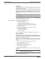

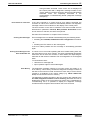
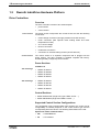

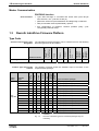
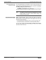

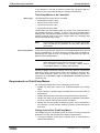
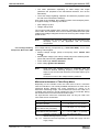
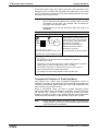
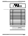


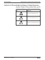
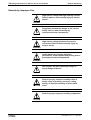


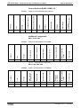

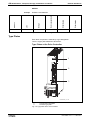
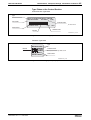


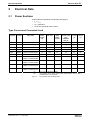

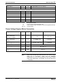
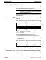


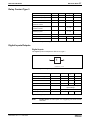
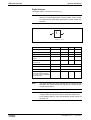


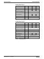
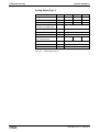
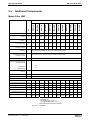

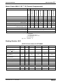
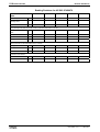
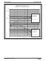


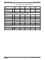

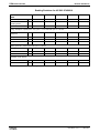
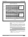
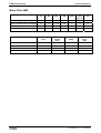
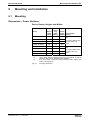

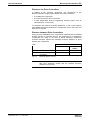
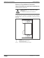


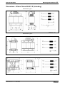
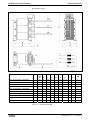
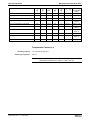

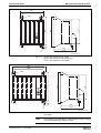
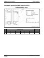
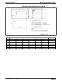

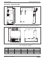

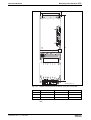

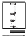
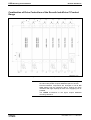
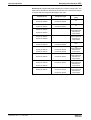


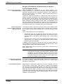
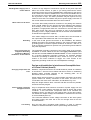


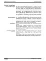
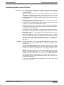

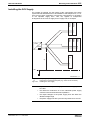
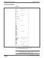

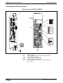
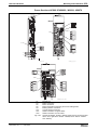
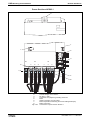

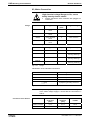
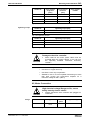

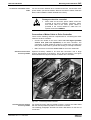

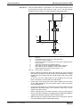


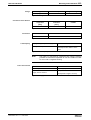
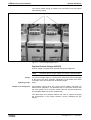


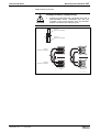
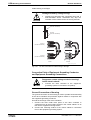


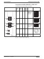
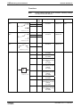


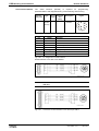
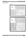


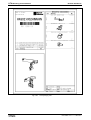

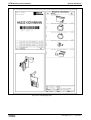
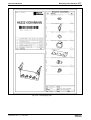
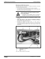
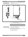
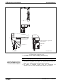

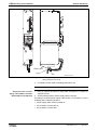


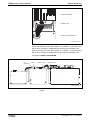


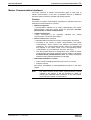


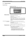

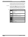


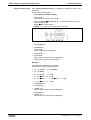

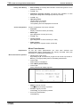
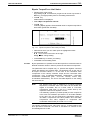
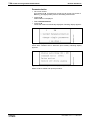
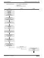
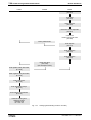
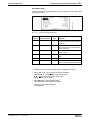
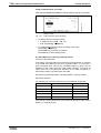
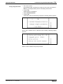

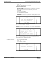

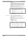
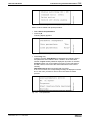


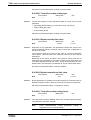
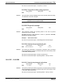


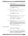
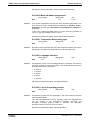


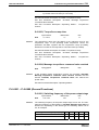

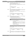

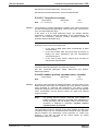
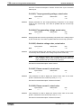
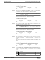
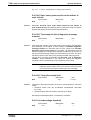

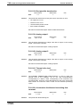

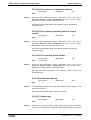
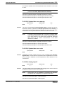

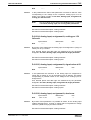

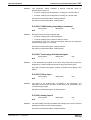


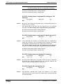
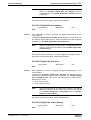
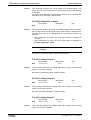

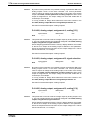
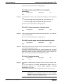
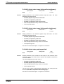
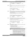

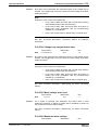
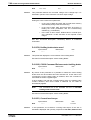


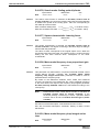
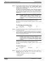


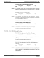
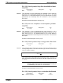


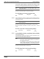
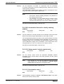

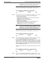
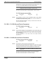


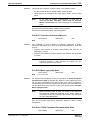
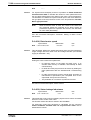
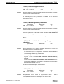
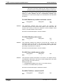

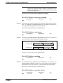

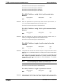
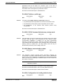

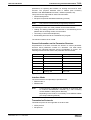
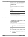

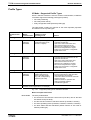
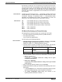
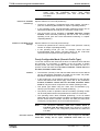
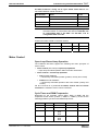


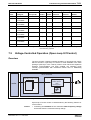

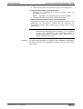

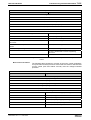
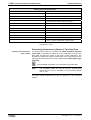
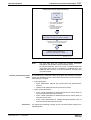
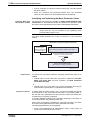
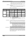

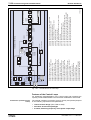

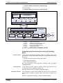
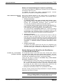
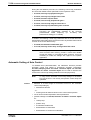
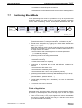

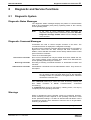
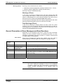
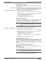


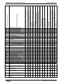
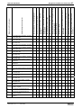

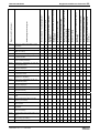


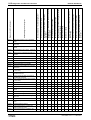
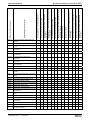

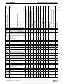
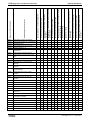


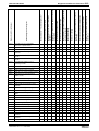
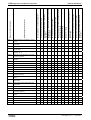
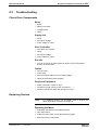


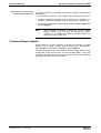
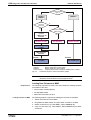
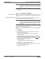
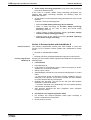
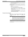

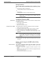

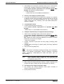
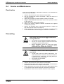

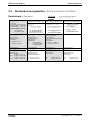

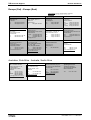


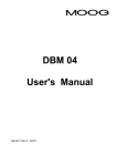
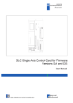

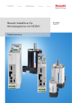
![[Download] azionamenti-hcs01](http://vs1.manualzilla.com/store/data/006141009_1-1242967de3765f3b826dc0b688197751-150x150.png)