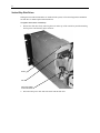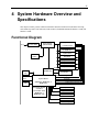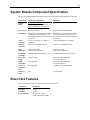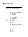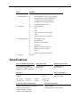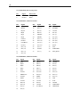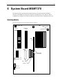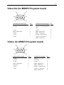
1
Rack-Mount Workstation/Server System Reference November 1997 DHAF02430 Warranties and Liabilities The information and the software discussed in this document are subject to change without notice and should not be considered commitments by Intergraph Corporation. Intergraph Corporation assumes no responsibility for any errors in this document. The software discussed in this document is furnished under a license and may be used or copied only in accordance with the terms of the license. No responsibility is assumed by Intergraph for the use or reliability of software on equipment that is not supplied by Intergraph or its affiliated companies. All warranties given by Intergraph Corporation about equipment or software are set forth in your purchase contract, and nothing stated in, or implied by, this document or its contents shall be considered or deemed a modification or amendment of such warranties. Copyright 1997, Intergraph Corporation including this documentation, and any software and its file formats and audiovisual displays described herein; all rights reserved; may only be used pursuant to the applicable software license agreement; contains confidential and proprietary information of Intergraph and/or other third parties which is protected by copyright, trade secret and trademark law and may not be provided or otherwise made available without prior written authorization. Restricted Rights Legend Use, duplication, or disclosure by the United States Government is subject to restrictions as set forth in subdivision (c)(1)(ii) of the rights in technical data and computer software clause at DFARS 252.227-7013. Unpublished rights reserved under the copyright laws of the United States. Intergraph Corporation, Huntsville AL 35894-0001 Trademarks Intergraph and the Intergraph logo are registered trademarks, and StudioZ, RenderRAX, and InterServe are trademarks, of Intergraph Corporation. Other brands and product names are trademarks of their respective owners. FCC/DOC Compliance This equipment has been tested and found to comply with the limits for a Class A digital device, pursuant to part 15 of the FCC Rules. These limits are designed to provide reasonable protection against harmful interference when the equipment is operated in a commercial environment. This equipment generates, uses, and can radiate radio frequency energy. If the equipment is not installed and used in accordance with the instruction manual, it may cause harmful interference to radio communications. Operation of this equipment in a residential area is likely to cause harmful interference in which case the user will be required to correct the interference at his own expense. This digital apparatus does not exceed the Class A limits for radio noise emissions from digital apparatus set out in the Radio Interference Regulations of the Canadian Department of Communications. Warnings To reduce the risk of electrical shock, do not attempt to open the equipment unless instructed. Do not use a tool for purposes other than instructed. There is a danger of explosion if the battery is incorrectly replaced. Replace the battery only with the same or equivalent type as recommended by the manufacturer. Dispose of used batteries according to the manufacturer’s instructions. Notes Read all operating instructions before using this device. Keep these instructions for future reference. Follow all warnings on the device or in the operating instructions. v Contents Introduction.....................................................................................................................................ix Document Conventions .....................................................................................................................ix Additional System Information .........................................................................................................ix 1 Accessing the System....................................................................................................................1 Tools..................................................................................................................................................1 Opening the Base Unit .......................................................................................................................1 Protecting Against Electrostatic Discharge .........................................................................................2 Removing the Face Plate ....................................................................................................................2 Attaching the Face Plate.....................................................................................................................2 Closing the Base Unit.........................................................................................................................2 2 Servicing the System ....................................................................................................................3 Peripheral Drives ...............................................................................................................................4 Floppy Disk Drive ................................................................................................................4 CD-ROM Drive....................................................................................................................6 Vertical Bay Disk Drives ......................................................................................................8 Internal Bay Disk Drives ....................................................................................................11 Power Supply...................................................................................................................................12 Riser Card........................................................................................................................................13 P6 Bus Termination Card .................................................................................................................15 Processor Module for MSMT353 and MSMT359.............................................................................15 Processor Module for MSMT378......................................................................................................15 System Board...................................................................................................................................16 Fans .................................................................................................................................................17 Power Supply Fan...............................................................................................................17 System Fans .......................................................................................................................18 Internal Bay Fan .................................................................................................................18 Vertical Bay Fan.................................................................................................................18 Speaker ............................................................................................................................................19 Lithium (CMOS/Clock) Battery .......................................................................................................19 AC Line Filter..................................................................................................................................21 Keyswitch and LEDs........................................................................................................................21 3 Upgrading the System ................................................................................................................23 Adding Memory...............................................................................................................................23 Adding Processors to MSMT353 or MSMT359................................................................................24 Single to Dual Upgrade ......................................................................................................24 Dual to Quad Upgrade ........................................................................................................25 Adding Processors to MSMT378......................................................................................................26 Single to Dual Upgrade ......................................................................................................26 Pentium Pro to Pentium II Upgrade ....................................................................................26 Adding Option Boards .....................................................................................................................28 Installing an Option Board .................................................................................................28 Assigning System Resources...............................................................................................29 Adding Internal SCSI Drives ...........................................................................................................31 vi Adding External SCSI Drives ..........................................................................................................34 SCSI Cable Guidelines .......................................................................................................35 Connecting the Drive..........................................................................................................35 Disabling Sync Negotiation ................................................................................................35 4 System Hardware Overview and Specifications........................................................................37 Functional Diagram .........................................................................................................................37 System Board Combinations.............................................................................................................38 System Board Feature Summary.......................................................................................................38 System Boards Component Specification..........................................................................................39 Riser Card Features ..........................................................................................................................39 System Model Number.....................................................................................................................40 Specifications...................................................................................................................................41 Optional Hardware...........................................................................................................................42 5 System Board MSMT353 and MSMT359 ..................................................................................43 Connectors.......................................................................................................................................43 Jumpers..............................................................................................................................44 Cable Routing and Pinouts .................................................................................................46 Sound Controller..............................................................................................................................49 Address Resources for MSMT353 and MSMT359............................................................................50 DMA Channels ..................................................................................................................50 Input/Output Addresses ......................................................................................................50 Memory Address Map ........................................................................................................50 PCI to ISA Bus Interrupt Mapping .....................................................................................51 PCI Bus Configuration Space .............................................................................................51 ISA Bus..............................................................................................................................52 6 System Board MSMT378 ............................................................................................................53 Connectors.......................................................................................................................................53 Jumpers..............................................................................................................................54 Cable Routing and Pinouts .................................................................................................55 Sound Controller..............................................................................................................................58 Address Resources ...........................................................................................................................59 DMA Channels ..................................................................................................................59 Input/Output Addresses ......................................................................................................59 Memory Address Map ........................................................................................................59 PCI to ISA Bus Interrupt Mapping .....................................................................................60 ISA Bus..............................................................................................................................60 7 External Port Pinouts..................................................................................................................61 MIDI/Game .....................................................................................................................................62 Parallel ............................................................................................................................................62 SCSI ................................................................................................................................................63 Serial (COM) ...................................................................................................................................63 Ethernet 10/100 Base-TX .................................................................................................................64 Mouse and Keyboard........................................................................................................................64 Universal Serial Bus (for MSMT378 system board) ............................................................................65 Video (for MSMT353 or MSMT359 system board)..........................................................................65 VGA In (for MSMT353 or MSMT359 system board).......................................................................66 Video Out (for MSMT378 system board)..........................................................................................67 VGA In (for MSMT378 system board).............................................................................................67 vii 8 Riser Card MSMT463.................................................................................................................69 Expansion Slots ...............................................................................................................................69 Internal SCSI Controller ..................................................................................................................69 SCSI Connector ...............................................................................................................................70 Power Connector..............................................................................................................................70 Graphics Option Card Slot Assignments ..........................................................................................70 9 Peripherals ..................................................................................................................................73 SCSI CD-ROM Drive (CDSK178)...................................................................................................74 Disk Drives......................................................................................................................................74 CDSK111 (1 GB) ...............................................................................................................75 CDSK094 (2 GB) ...............................................................................................................76 CDSK098 (4 GB) ...............................................................................................................76 CDSK123, CDSK164, CDSK165, CDSK166, CDSK167 (4 GB)........................................77 Floppy Disk Drive (CDSK146).........................................................................................................77 Combo Drive (MESAM86) ..............................................................................................................78 EIDE CD-ROM Drive (CDSK177) ..................................................................................................79 10 Power Supply and Fans............................................................................................................81 Power Supply (MPWS145)...............................................................................................................81 DC Output Specifications ...................................................................................................81 Cable Connectors ...............................................................................................................82 P1 Pinout............................................................................................................................82 P2 - P7 Pinout ....................................................................................................................83 P9 Pinout............................................................................................................................83 P10 Pinout..........................................................................................................................83 System Fans.....................................................................................................................................83 Power Supply Fan (MCBLZ52 or CFAN1170) ...................................................................83 System Fans (MCBLY690).................................................................................................83 Vertical Bay Disk Drive Fan (MCBLY690) ........................................................................84 Internal Bay Disk Drive Fan (MCBLY690) ........................................................................84 Index ...............................................................................................................................................85 viii ix Introduction This System Reference provides the information necessary to service the following systems: u TDZ-425 RAX and TDZ-612 RAX workstations u StudioZ RenderRAX u InterServe 615R and 625R servers Document Conventions Bold Commands, words, or characters that you key in literally. Italic Variable values that you supply, or cross-references. Monospace Output displayed on the screen. SMALL CAPS Key names on the keyboard, such as D, ALT or F3. Names of files and directories. You can type filenames and directory names in the dialog boxes or the command line in lowercase unless directed otherwise. CTRL+D Press a key while simultaneously pressing another key; for example, press CTRL and D simultaneously. Additional System Information A System Setup is shipped with each system, and provides detailed information about: u u u u Configuring the operating system and associated system software Using the system Using the AMIBIOS Setup program Installing system software A System Introduction is delivered with the system, and provides information about: u Intergraph Support u System hardware features u Available hardware option x 1 1 Accessing the System This chapter lists hand tools and describes servicing restrictions, opening the base unit, avoiding electrostatic discharge, removing and attaching the face plate, and closing the base unit. This system features a telescoping chassis that provides increased serviceability and access to internal components. The telescoping section, to which the system board is mounted, is secured by five screws and slides out from the rear. NOTE “Right side” and “left side” are as seen from the front of the base unit. CAUTION Follow all warnings and cautions in servicing instructions. Personal injury and damage to equipment can occur if documented procedures are not followed. CAUTION Use an antistatic wrist strap for all ser vicing procedures to avoid the possibility of electrostatic discharge. Tools You will need the following tools to service the system: u u u u u u Antistatic wrist strap Quarter-inch nutdriver No. 1 and No. 2 Phillips screwdrivers Three-sixteenth-inch nutdriver Five-sixteenth-inch or 8 mm nutdriver Small single-slot screwdriver Opening the Base Unit CAUTION Shut the system down and turn the system power off. Use caution to avoid injury when removing covers and other hardware. CAUTION If the system is installed in a free-standing rack, ensure front and side stabilizers are fully extended. To open the base unit: 1. Remove the screws that secure the face plate to the rack. 2. Slide the system out of the rack until it locks in the extended position. 3. Remove the following eight screws that secure the cover to the chassis: One at right and left top corners of face plate; two at top, back of cover; and two at right and left sides, back of cover. 4. Slide the cover back about an inch, then lift the cover off. 5. Attach grounding clip from antistatic wrist strap to bare metal. 2 Protecting Against Electrostatic Discharge Sensitive components inside the base unit can be damaged by static electricity. To protect against this possibility, take the following precautions when working with the system’s internal components. u Touch the bare metal of the base unit to ensure it and your body are at the same electric potential. u Handle all printed circuit boards as little as possible and by the edges only. Leave new parts in their protective packaging until you install them. u Use a disposable or reusable antistatic wrist strap when servicing or upgrading the system. Once a disposable wrist strap is used, it cannot be used again. A reusable antistatic wrist strap can be attached to any bare metal part of the base unit. The metal conductor bead in the elastic sleeve of reusable antistatic straps must contact bare skin. Removing the Face Plate To remove the face plate: 1. Remove the cover. 2. Remove one lower screw on each side of system front that secures handle to the base unit. 3. Remove the six screws that secure face plate to the base unit. 4. Pull the face plate toward you to remove it. Note how the bottom lip of the face plate attaches to the cutout in front of the power supply. Attaching the Face Plate To attach the face plate: 1. Push the face plate onto the base unit. Ensure that the top part of the lip at bottom slides over the cutout in front of the power supply. 2. Adjust the face plate as needed to ensure all components are flush. 3. Secure the face plate to the base unit. 4. Close the cover. Closing the Base Unit CAUTION After servicing the system, always replace the covers that were removed. The covers ensure the system maintains proper air flow, so internal components do not overheat and fail. The covers also ensure that electromagnetic interference (EMI) emissions remain below the standard requirements. To close the base unit: 1. Remove the antistatic wrist strap from the base unit. 2. Replace the cover. 3. Slide the base unit into the rack. 4. Secure the base unit with screws at each corner of the face plate. 3 2 Servicing the System This chapter describes how to replace the standard parts within the system. NOTE Refer to Chapter 1 for details on opening the system and protecting against electrostatic discharge. CAUTION Follow all warnings and cautions in servicing instructions. Personal injury and damage to equipment can occur if documented procedures are not followed. CAUTION Use an antistatic wrist strap for all servicing procedures to avoid the possibility of electrostatic discharge. The following shows the location of major parts in the system. Unit with MSMT353 system board is shown. Internal Drive Bay Riser Card Brace Horizontal Drive Bay Disk Drive Fan Vertical Drive Bay Riser Card System Board Processor Module or P6 Bus Termination Card (MSMT353 or MSMT359 only) Floppy Drive Memory Power Supply PCI Card Guide 4 Peripheral Drives Floppy Disk Drive To replace the floppy disk drive: 1. Disconnect the power cable and floppy cable from the drive as shown in the following figure. Note the position of the red stripe on the floppy cable. 2. Remove the two screws securing the drive bracket to the power supply. Power Cable Floppy Cable Screw (One each side) 5 3. Remove the four screws securing the bracket to the drive as shown in the following figure. Screws (Two each side) 4. Attach the new drive to the bracket and attach it to the power supply. Connect the power cable and floppy cable. Ensure the red stripe on the floppy cable is oriented correctly. 5. Close the base unit. 6 CD-ROM Drive Depending on system options, the CD-ROM drive may be a SCSI drive or an EIDE drive. Refer to Chapter 9, “Peripherals,” for details. To replace the CD-ROM drive: 1. Disconnect the power cable, data cable, and audio cable from the CD-ROM drive as shown in the following figure. Note the position of the stripe on the data cable. 2. Remove the screws securing the horizontal bay to the base unit. Screw Horizontal Bay Screw Audio Cable Data Cable Power Cable 7 3. Remove the four screws securing the drive to the drive bay as shown in the following figure. Screws (Two each side) 4. Set the SCSI ID on a new SCSI drive to the same ID as the old drive. On a new EIDE drive, set the mode select header to “master.” Refer to Chapter 9, “Peripherals,” for details. 5. Attach the new drive to the horizontal bay and attach it to the base unit. Connect the power cable, data cable, and audio cable. Ensure the stripe on the data cable is oriented correctly. 6. Close the base unit. 8 Vertical Bay Disk Drives If Kingston removable disk modules are installed in the system, refer to the Kingston documentation for disk drive or module replacement instructions. To replace drives in the vertical bay: 1. Remove the disk drive fan by removing the screw at the top of the vertical bay and disconnecting the fan power cable from the inline connector. Screw Fan Fan Power Cable In-line Connector 2. Disconnect the power cable and SCSI cable from the disk drive. 9 3. Remove the screws securing the disk drive at the top of the vertical bay as shown in the following figure. Screws 4. Pull out the black disk drive tray through the front of the system. The disk drive is attached to the tray. 10 5. Remove the slot filler by removing screws as shown in the following figure; then remove the four screws securing the disk drive to the tray. Screws Drive Tray Slot Filler Screws (Two each side) 6. Set the SCSI ID on the new disk drive to the same SCSI ID as on the old disk drive. 7. Attach the new disk drive to the tray and slide it into the vertical bay. 8. Secure the drive to the bay. 9. Connect the SCSI cable and power cable to the disk drive. 10. Replace the disk drive fan and connect the fan power cable. 11. Close the base unit. 11 Internal Bay Disk Drives To replace drives in the internal bay: 1. Disconnect the SCSI cable and power cable from the disk drive as shown in the following figure. 2. Disconnect the fan cable. Note the location where the fan cable connects to the system board. 3. Remove the two screws that secure the internal bay to the base unit. 4. Slide the internal bay toward the front until it disengages; then lift it out of the system. Screws Internal Bay SCSI Cable Fan Cable Power Cable Screws 5. Remove the screws that secure the disk drive to the internal bay. Two screws are on top, as shown, and two are on the bottom. 6. Remove the disk drive from the bay. 7. Set the SCSI ID on the new disk drive to the same SCSI ID as on the old disk drive. 8. Attach the new disk drive to the internal bay. 9. Place the internal bay into the base unit, and slide it toward the rear until it engages. 10. Attach the bay to the base unit. 11. Connect the SCSI cable and power cable to the disk drive. 12. Connect the fan cable to the system board. 13. Close the base unit. 12 Power Supply To replace the power supply: 1. Open the unit and remove the face plate as described in Chapter 1. 2. Disconnect all power cables from the internal devices (riser card, floppy disk drive, internal disk drive bay, vertical and horizontal disk drive bays, and speaker). Power Supply Screw Riser Card Brace 3. Disconnect the AC power cable from the rear of the power supply. (The AC power cable is routed from the line filter). 4. Remove the floppy drive and the horizontal drive bay. Refer to the respective procedures earlier in this chapter. 5. Disconnect the speaker cable and remove the speaker. (Any system with the MSMT378 system board does not have a speaker). Refer to the “Speaker” procedure later in this chapter. 6. Remove the screw securing the power supply to the base unit. 7. Pull the power supply forward until it disengages; lift up to remove it. 13 8. Place the new power supply into the base unit, and push it forward until it engages. 9. Secure the power supply to the base unit. 10. Connect the power cables to the internal devices. 11. Connect the AC power cable to the power supply. 12. Attach the floppy drive and horizontal drive bay. 13. Install the speaker and connect the speaker cable. 14. Install the face plate and cover. Riser Card To replace the riser card: 1. Open the base unit as described in Chapter 1. 2. Remove all installed option boards. If ISA boards are installed, remove the internal disk drive bay, and then remove the ISA cards. Refer to “Internal Bay Disk Drives” earlier in this chapter. 3. Disconnect the SCSI cable and power cable from the riser card. 4. Remove the screw that secures the riser card brace to the top of the PCI card guide. 5. Loosen the two screws that secure the riser card brace to the PCI card guide, slide the card guide back, and remove the card guide. Note how the PCI card guide fits over the lip on the rear of the power supply. Screw Riser Card Riser Card Screws PCI Card Guide Screws Power Supply 14 6. Remove the two screws securing the riser card brace to the back of the system. Screws Riser Card (PCI Card Slots) Riser Card Brace 7. Remove the two screws that secure the riser card to the brace. 8. Remove the riser card brace. 9. Grasp the riser card firmly on both ends, and carefully pull straight up until the card disengages. 10. Insert the new riser card into the system board connector. Press firmly over the center of the PCI connectors to fully seat the card. CAUTION Do not rock the riser card back and forth; pins inside the connector may be damaged as a result. Press firmly so the card connector slides evenly into the slot. 11. Install the riser card brace, and install the two screws securing the card to the brace. 12. Place the PCI card guide on the two screws attached to the riser card. Slide the guide over the lip on the rear of the power supply, then tighten the screws. 13. Attach the top of the riser card brace to the PCI card guide. 14. Replace the two screws securing the rear of the riser card brace to the back of the system. 15. Connect the power and SCSI cable to the riser card. 16. Replace any PCI or ISA option boards, and the internal drive bay (if removed). 17. Close the base unit. 15 P6 Bus Termination Card The P6 bus termination card, MSMT311, is used only in systems with the MSMT353 or MSMT359 system board that has one or two processors. Refer to Chapter 5, “System Board MSMT353 and MSMT359,” for details. To replace the P6 Bus termination card: 1. Open the base unit. 2. Remove the installed PCI cards. The termination card is attached to the system board adjacent to the memory modules. 3. Remove the screws securing the termination card to the system board. 4. Carefully disengage the card from the system board and remove it. 5. Attach the new card to the system board, and secure the card with the screws. 6. Replace the PCI cards. 7. Close the base unit. Processor Module for MSMT353 and MSMT359 The replacement processor module, MSMT364 or MSMT310, for the MSMT353 and MSMT359 system board, includes pre-installed voltage regulator modules(VRMs) and processors. To replace the processor module: 1. Open the base unit. 2. Remove the installed PCI cards. The processor module is attached to the system board adjacent to the memory modules. 3. Remove the left VRM to access mounting screw. 4. Remove the screws securing the processor module to the system board. 5. Carefully disengage the module from the system board and remove it. 6. Attach the new processor module to the system board, and secure it with the screws. 7. Reinstall the left VRM. 8. Replace the PCI cards. 9. Close the base unit. Processor Module for MSMT378 The Pentium Pro and Pentium II processors for the MSMT378 system board are housed in plastic processor modules, which have heat sinks attached to one side. When a Pentium II module is installed into an S1 slot, the heat sinks are supported at the bottom by a black plastic bar, which runs between the two bottom-most rows of heat sink fins. The support bar is connected to a support assembly via four posts. 16 WARNING Setting processor voltage incorrectly may destroy the processor! Refer to Chapter 6, “System Board MSMT378,” for details. To replace the processor module: 1. NOTE Remove ISA cards if installed. Pentium Pro processor modules do not require heat sink support. 2. Remove the top section of the heat sink support, if necessary. The plastic support bar has a tab on each end. Press both tabs inward, towards each other, while using a pulling motion to pull the bar away from the heat sink fins. The support assembly is permanently connected to the system board, and need not be removed. 3. Remove the processor module. Grasp both tabs on the top corners of the processor module and press them inward, towards each other. Then pull the entire module upward, keeping the tabs pressed inward. Heat sinks are permanently connected to the module, and need not be removed. 4. If necessary, set the frequency for the new processor by adjusting jumpers J47 through J50. Refer to Chapter 6, “System Board MSMT378,” for more information. 5. Align the new processor module over the S1 slot and firmly press it down into the slot. 6. If necessary, replace the top section of the heat sink support. Gently push the plastic support bar toward the four posts on the heat sink support assembly, until the bar snaps into place. 7. Reinstall the ISA cards. System Board Replacement system boards contain pre-installed voltage regulator modules and processors. However, you must swap the memory modules and P6 bus termination card (on MSMT353 or MSMT359) or processor module from the old system board to the new one. NOTE Steps 10 and 14 apply only to the the MSMT353 or MSMT359 system board. The telescoping (modular) chassis makes it easier for you to replace the system board. You must remove the unit from the rack before replacing the system board. WARNING Two people must remove the unit from the rack. Failure to do so can result in personal injury and equipment damage. The unit is heavy and difficult to handle. To replace the system board: 1. Disconnect all external cables from the unit and remove it from the rack. Use a helper! 2. Open the base unit as described in Chapter 1. 3. Remove the riser card and any installed option cards as described earlier in this chapter. 4. Remove the five screws securing the telescoping section to the base unit. There are two screws on the right and three on the left. 5. Pull the telescoping section toward you a few inches. 6. Disconnect all internal cables attached to the system board. Note the locations where the cables are connected. 7. Remove the telescoping section from the base unit. 8. Remove the jackscrews from the parallel and serial ports, and from the three audio jacks. 17 9. Remove the memory modules from the system board, and place them on an antistatic surface. 10. Remove the processor module (for quad processor systems) or the P6 bus termination card (for dual processor systems) from the MSMT353 or MSMT359 system board as described earlier in this chapter. 11. Remove the eight screws securing the system board to the telescoping section. 12. Lift the system board out of the unit. 13. Install the new system board and secure it with the eight screws. 14. Attach the processor module or P6 bus termination card to the MSMT353 system board. 15. Install the memory modules on the system board. 16. Connect the internal cables to the system board. If you need help identifying cable connections, refer to Chapter 5 for the MSMT353 or MSMT359 system board or Chapter 6 for the MSMT378 system board. 17. Secure the parallel and serial ports and audio jacks with the jackscrews. 18. Slide the telescoping section into the base unit. Ensure that all tabs engage correctly. 19. Install the five screws that secure the telescoping section to the base unit. 20. Install the riser card and option cards, and connect the internal SCSI cable to the riser card. 21. Reinstall the unit in the rack. Use a helper! 22. Close the base unit and reconnect the external cables. Fans Refer to Chapter 10, “Power Supply and Fans,” for details on fans. NOTE Airflow in the system is front to back. Arrows on the fan indicate airflow direction and rotation. Ensure that you install fans with arrows pointing to the back of the system. Power Supply Fan To replace the power supply fan: 1. Open the base unit. 2. Remove the power supply as described earlier in this chapter. 3. Disconnect the fan power cable. 4. Note the airflow direction of the fan, and then remove the four screws securing the fan to the power supply housing. 5. Install the new fan on the power supply housing. 6. Reinstall the power supply and connect the fan power cable. 7. Close the base unit. 18 System Fans To replace a system fan: 1. Open the base unit. 2. Remove the power supply as described earlier in this chapter. 3. Disconnect the fan power cables. 4. Note the airflow direction of the fan, and then remove the four screws securing the fan to the power supply housing. 5. Install the new fan on the power supply housing and connect the fan power cable. 6. Reinstall the power supply and close the base unit. Internal Bay Fan To replace the internal disk drive bay fan: 1. Open the base unit. 2. Disconnect the internal disk drive fan power cable. 3. Remove the four screws securing the fan to the internal disk drive bay at the rear of the unit. Note the airflow direction of the fan. Fan Screws 4. Install the new fan and connect the fan power cable. 5. Close the base unit. Vertical Bay Fan To replace the vertical disk drive bay fan: 1. Open the base unit. 2. Disconnect the fan power cable and remove the screw from the top of the fan bracket. For an illustration, refer to the “Vertical Bay Disk Drives” procedure earlier in this chapter. 3. Remove the fan from the fan bracket. Note the orientation of the fan. 4. Install the new fan on the bracket and install the bracket on the vertical disk drive bay. 5. Connect the fan power cable and close the base unit. 19 Speaker A speaker is not installed in systems with the MSMT378 system board. To replace the speaker: 1. Remove the face plate. Six screws on the front and one screw on each lower side secure the face plate to the system. 2. Remove the two screws securing the floppy drive to the power supply, and set the drive aside carefully. 3. Note the position of the red wire and disconnect the speaker cable connector from the system board. 4. Remove the screws that secure the speaker retaining ring to the power supply, and remove the ring and speaker. Access holes are provided on top of the power supply housing. 5. Place the retaining ring on top of the new speaker, insert the assembly into the power supply housing, and secure the ring with the screws. 6. Connect the speaker cable. 7. Attach the floppy disk drive. 8. Attach the face plate. Lithium (CMOS/Clock) Battery On the MSMT353 or MSMT359 system board, the battery is located to the right of the riser card, near the back. On the MSMT378 system board, the battery is located near the memory modules on the left side. WARNING There is a danger of explosion if the battery is incorrectly replaced. WARNING Replace the battery with the same or equivalent type only, as recommended by the manufacturer. Dispose of used batteries according to the manufacturer’s instructions. To replace the battery (on MSMT353 or MSMT359 system board): 1. Remove the ISA cards, if installed. (You must remove the internal drive bay if ISA cards are installed. Refer to “Installing an Option Board ” in Chapter 3 for details). 2. Note the positive orientation of the battery. Carefully remove the discharged battery by grasping it firmly and lifting upward. 3. Install the new battery in the same orientation as the old battery. 4. Install the ISA cards and install the internal drive bay. 5. Dispose of the battery according to the manufacturer’s instructions. 20 Battery ISA Card Slots To replace the battery (on MSMT378 system board): 1. Remove any PCI cards that interfere with access to the battery. Battery 2. Carefully remove the discharged battery by grasping it firmly and lifting upward. 3. Install the new battery in the same orientation as the discharged battery. 4. Replace the PCI cards that you removed in step 1 above. 21 AC Line Filter You must remove the unit from the rack before replacing the AC line filter. This component ordinarily does not require replacement unless it has been damaged by current surges or other AC power problems. WARNING Two people must remove the unit from the rack. Failure to do so can result in personal injury and equipment damage. The unit is heavy and difficult to handle. To replace the AC line filter: 1. Remove the unit from the rack. Use a helper! 2. Open the cover. 3. Disconnect the power cable from the top of the line filter. 4. Remove the right rail from the base unit. 5. Remove the four screws securing the line filter to the base unit. 6. Lift the line filter from the base unit. 7. Install the new line filter in the base unit and connect the power cable. 8. Install the right rail. 9. Install the cover. 10. Install the unit into the rack. Use a helper! Keyswitch and LEDs To replace the keyswitch: 1. Open the cover and remove the face plate as described in Chapter 1. 2. Remove the two screws securing the keyswitch and LED bracket to the base unit. The screws are underneath the base unit. Screws 22 3. Pull the bracket forward slightly, note the location of the LED cables, and disconnect the cables. 4. Remove the keyswitch from the bracket. 5. Remove the keyswitch cable from the cable clip near the front of the system board, and disconnect the cable at the inline connector. 6. Install the new keyswitch with the arrow pointing up, place the keyswitch cable into the cable clip, and connect the cable at the inline connector. 7. Connect the LED cables and secure the bracket to the base unit. 8. Attach the face plate and install the cover. To replace the LEDs: 1. Perform steps 1 through 4 above. 2. Remove both LEDs. 3. Install the two new LEDs. 4. Connect the LED cables and secure the bracket to the base unit. 5. Attach the face plate and install the cover. 23 3 Upgrading the System This chapter describes adding memory, processors, option boards, internal SCSI drives, and external SCSI drives for all rack-mount systems. NOTE Refer to Chapter 1 for details on opening the base unit and protecting against electrostatic discharge. CAUTION Follow all warnings and cautions in servicing instructions. Personal injury and damage to equipment can occur if documented procedures are not followed. CAUTION Use an antistatic wrist strap for all servicing procedures to avoid electrostatic discharge. Adding Memory You can upgrade memory on the MSMT353 or MSMT359 system board in 32 MB, 64 MB, 128 MB, and 256 MB increments; and the MSMT378 system board in 32 MB, 64 MB, and 128 MB increments. RenderRAX systems ship with all eight SIMM sockets populated. Memory upgrade kits from Intergraph contain two SIMMs and a disposable antistatic wrist strap. CAUTION System memory modules available from Intergraph have been certified for use with Intergraph computers at extremes of temperature and system load to ensure reliable performance. System memory modules available from other vendors may not function properly or reliably in your Intergraph computer. To avoid damaging the SIMMs and voiding the warranty, take the following precautions. u Do not bend, twist, drop, or otherwise handle the SIMMs carelessly. u Do not expose the SIMMs to moisture or extreme temperatures. u Do not remove the SIMMs from the antistatic bag until installation. Follow these SIMM population rules to correctly install the SIMMs. u Each bank has two slots. Fill both slots in a bank. u Use the same size SIMM in both slots in a bank. u After adding or replacing SIMMs, restart the computer. The new memory configuration is detected automatically. The following table shows valid memory configurations. Each bank contains two sockets, and both sockets must be populated. Memory density must be the same in all populated sockets. NP designates the bank is not populated. Supported Memory Bank 0 Bank 1 Bank 2 Bank 3 64 MB 2 x 32 MB NP NP NP 128 MB 2 x 64 MB 2 x 32 MB 2 x 128 MB NP 2 x 32 MB NP NP NP NP NP NP NP 256 MB 24 Supported Memory Bank 0 Bank 1 Bank 2 Bank 3 2 x 64 MB 2 x 32 MB 2 x 64 MB 2 x 32 MB NP 2 x 32 MB NP 2 x 32 MB 512 MB 2 x 128 MB 2 x 64 MB 2 x 128 MB 2 x 64 MB NP 2 x 64 MB NP 2 x 64 MB 1 GB 2 x 128 MB 2 x 128 MB 2 x 128 MB 2 x 128 MB To install the memory upgrade: 1. Open the base unit and remove the necessary parts as described in Chapter 1. 2. Remove the graphics boards and other installed PCI option boards. 3. Remove the existing SIMMs from their sockets before adding new ones. 4. Remove the SIMMs from the antistatic bag and install them in the following order: − For system board MSMT353 or MSMT359, if the total number of installed SIMMs will be four, install the SIMMs in the Bank 1 sockets first, then in the Bank 0 sockets. − For system board MSMT353 or MSMT359, if the total number of installed SIMMs will be eight, install the first SIMM in socket J58. Install the remaining SIMMs in the next empty socket until socket J51 is the last socket populated. − For system board MSMT378, install the first SIMM in the first available socket. 5. Position the SIMM in the next available socket so that the notch faces the back of the base unit. 6. Insert the SIMM at a 60 degree angle, pressing it firmly into the socket. 7. Push on the top edge of the SIMM until it snaps into the metal clips. The socket tabs must fit inside the mounting holes of the SIMM. 8. Repeat steps 5 through 7 for the remaining SIMMs. 9. Replace the graphics and PCI option boards and close the base unit. 10. Restart the system. The new memory is recognized automatically. Adding Processors to MSMT353 or MSMT359 You cannot add processors to the MSMT353 system board, since it ships with quad processors. The MSMT359 system board allows you to upgrade a single processor to dual processors and dual processors to quad processors. For the MSMT378 system board, you can upgrade a single processor to dual processors and Pentium Pro to Pentium II. 25 Single to Dual Upgrade Single to dual processor upgrade kits include a CPU with attached heat sink, a voltage regulator module (VRM), and a metal clip. To upgrade a single processor system: 1. NOTE Open the base unit and remove the necessary parts as described in Chapter 1. If full-length ISA option boards are installed, they must be removed to access the CPU sockets. 2. Find the empty processor socket (adjacent to the existing CPU) on the system board. Raise the lever on the empty socket to open the socket. 3. Install the new CPU into the socket. The CPU socket is keyed to ensure proper insertion. 4. Lower the lever to lock the CPU in the socket. 5. Attach the metal clip over the new CPU. Examine how the clip on the first CPU is installed to see how it should fit on the new CPU. Ensure each end of the clip fully engages the socket tabs. 6. Attach the VRM into the empty VRM socket. Ensure the release tabs in the VRM socket fully engage the VRM. The following figure shows the completed upgrade with the new CPU and VRM installed. CPU VRM Socket Socket Metal Clip 7. Replace any full-length ISA option boards and close the base unit. Dual to Quad Upgrade Dual to quad upgrade kits contain a processor module with two pre-installed processors and voltage regulator modules (VRMs), and screws. 26 To upgrade a dual processor system: 1. NOTE Open the base unit and remove the necessary parts as described in Chapter 1. If PCI option boards are installed, remove to access the quad processor sockets. 2. Remove the P6 bus termination card. The processor module will be installed in this location. 3. Align the processor module with the sockets and carefully insert the module. 4. Press the processor module firmly into the sockets. 5. Remove the left VRM. 6. Secure the processor module with screws supplied in the kit. 7. Install the left VRM. 8. Install any PCI option boards and close the base unit. 9. Return the P6 bus termination card to the Intergraph Repair Depot. Adding Processors to MSMT378 The MSMT378 system board allows you to upgrade the system from single to dual processors, and from Pentium Pro processors to Pentium II processors. Single to Dual Upgrade To install a new processor module: 1. Open the base unit and remove the ISA cards. 2. Set the frequency, if necessary, for the new processor by adjusting jumpers J47 through J50. Refer to Chapter 6, “System Board MSMT378,” for more information. 3. Align the new processor module over the S1 slot and firmly press it down into the slot. 4. If necessary, replace the top section of the heat sink support. Gently push the plastic support bar toward the four posts on the heat sink support assembly, until the bar snaps into place. 5. Reinstall the ISA cards and close the base unit. Pentium Pro to Pentium II Upgrade The Pentium Pro and Pentium II processors for the MSMT378 system board are housed in plastic processor modules, which have heat sinks attached to one side. When a Pentium II module is installed into an S1 slot, the heat sinks are supported at the bottom by a black plastic bar, which runs between the two bottom-most rows of heat sink fins. The support bar is connected to a support assembly via four posts. WARNING Setting processor voltage incorrectly may destroy the processor! Refer to Chapter 6, “System Board MSMT378,” for details. To upgrade Pentium Pro module with Pentium II module: 1. Open the base unit and remove ISA cards if installed. 2. Remove the top section of the heat sink support, if necessary. The plastic support bar has a tab on each end. Press both tabs inward, towards each other, while using a pulling motion to pull the 27 bar away from the heat sink fins. The support assembly is permanently connected to the system board, and need not be removed. 3. Remove the Pentium Pro processor module. Grasp both tabs on the top corners of the processor module and press them inward, towards each other. Then pull the entire module upward, keeping the tabs pressed inward. Heat sinks are permanently connected to the module, and need not be removed. 4. Remove the voltage jumper from J19, and place it on jumper J39. Refer to the following figure. Also refer to Chapter 6, “System Board MSMT378,” for details on jumper settings. 5. Install the heat sink support assembly to the system board. The assembly snaps into place in two of the indicated holes. Refer to the following figure. CPU 0 Socket for CPU 1 Clock Voltage J39 SCSI J39 J34 J33 Host Bus Frequency J33, J34 J49 J50 J47 J48 J19 CPU Frequency Holes for Heat Sink Supports Clock Voltage J23 J24 Host Bus Frequency 6. Reinstall the ISA cards and close the base unit. 28 Adding Option Boards Peripheral Component Interconnect (PCI), non-compliant PCI, Industry Standard Architecture (ISA), and Plug-n-Play (PnP) option boards may be installed in the system. A general description of the types of boards is provided below. u PCI boards contain configuration registers that define resource information to the system during startup. PCI boards do not require manual system configuration when installing the board. The system BIOS detects the board’s presence during startup and reads information from the board’s configuration registers to assign the necessary system resources. The system’s PCI slots are limited to 25 Watts power dissipation per the Peripheral Component Interconnect Specification, 2.1. Installed PCI boards must draw less than 25 Watts of power. Also, the total power consumed by all PCI boards in the system should be less than 180 Watts. NOTE All PCI option boards sold by Intergraph fully comply with the Peripheral Component Interconnect Specification, 2.1. u Non-compliant PCI boards mechanically comply with the Peripheral Component Interconnect Specification 2.1, but do not contain configuration registers that allow the system to automatically assign the necessary resources. These boards install in PCI slots, but you assign system resources manually using the System Configuration Utility (SCU) before installing the board. In this regard, they are like ISA boards, as described below. u ISA boards do not contain registers that define the resource information to the system during startup. Therefore, you must run the SCU to define the board to the system before installing the ISA board. This reserves system resources for the board and prevents conflicts with ISA option boards already installed. Refer to the section, “Assigning System Resources” later in this chapter. u PnP boards are ISA boards that contain configuration registers like PCI boards. During startup, the system BIOS automatically detects the installed board and assigns the necessary system resources. Since PnP boards are ISA-based boards, they must be installed in the ISA slots. PCI slots are on Side One of the riser card; ISA slots are on Side Two. NOTE Assign system resources for ISA and non-compliant PCI boards before installation. Refer to the section, “Assigning System Resources” later in this chapter. Installing an Option Board To install option boards: 1. Open the base unit as described in Chapter 1. If installing an ISA card, the internal disk drive bay must be removed to access ISA slots. Refer to “Internal Bay Disk Drives” in Chapter 2 for instructions on removing the internal disk drive bay. 2. Using a quarter-inch nutdriver, remove the blanking plate from an available slot. If installing a PCI card, loosen the two screws securing the board clip to the PCI card guide (just behind the power supply), and slide the board clip forward. 3. Install the option board. Press firmly to ensure the board seats completely into the slot. 4. Secure the board to the chassis using the screw removed previously. If installing a PCI card, slide the board clip back and tighten the two screws. 5. Connect any cables to the board as required by the manufacturer. 6. Close the base unit and restart the system. 29 NOTE For PnP boards, notice when the following message displays: Hit DEL if you want to run SETUP. Press DELETE to run AMIBIOS Setup, and enable the Boot to PnP Operating System parameter under PnP Setup menu. Exit AMIBIOS Setup and restart the system. Assigning System Resources Some option boards include a configuration diskette that you can use to reserve the system resources required for the board. Other option boards do not include a diskette, but require that you manually enter the configuration information. The next two sections describe how to reserve the resources for both types. The System Configuration Utility (SCU) is an MS-DOS utility that will not run in the Windows NT environment. Use the System Utilities (SYSUTIL) diskette delivered with your system to boot the system into MS-DOS. The system must be set to boot from the floppy disk drive (normally drive A) to use the SCU. If necessary, refer to “Changing the System Boot Sequence” in the System Setup. NOTE For a list of available system address resources (DMA, I/O, memory) refer to Chapter 5 or 6. NOTE Treat non-compliant PCI boards and PC Cards as ISA boards for assigning system resources. Option Boards with a Configuration File Some ISA boards are shipped with a diskette containing a configuration file. The configuration file can be loaded to the system so that the BIOS reads this file to assign resources during startup. If you install ISA boards that are shipped with a configuration diskette, follow this procedure. NOTE If a configuration diskette is not delivered with the option board, refer to “Option Boards without a Configuration File.” To configure option boards with a configuration file: 1. Shut down and power off the system. 2. Insert the SYSUTIL diskette into the floppy diskette slot of the combo drive; then restart the system. 3. When the MS-DOS Startup menu displays, select option 1 to run the SCU. 4. Use the arrow keys or the mouse to select Step 2 from the SCU Main Menu. Then press to add a board that was not detected or has not been installed. INSERT A prompt displays requesting you to copy the configuration files needed to configure the system. The configuration file is on a diskette provided by the ISA board manufacturer. 5. Press ENTER to accept A:\ as the path to the configuration file. 6. Select the slot where the board will be installed. Slots 1 through 4 are valid for ISA boards, slots 1 through 12 are valid for PCI boards. 7. When prompted to insert the source disk, insert the diskette containing the configuration file and press ENTER. 8. When prompted to insert the destination disk, insert the SYSUTIL diskette and press ENTER. The configuration file from the option board manufacturer will be installed to the system and to the SYSUTIL diskette. 9. Press ESC to return to the SCU Main Menu. 30 10. Select Step 4 of the SCU Main Menu to save the configuration, and then select Step 6 of the SCU Main Menu to exit the SCU. 11. Remove the diskette from the combo drive and shutdown the system. 12. Install the option board as described in “Installing an Option Board” previously in this chapter. 13. Restart the system. Option Boards without a Configuration File Some board vendors do not include configuration files with their boards. For these boards, you must use the System Configuration Utility (SCU) to define the board to the system. To configure option boards without a configuration file: 1. Shut down and power off the system. 2. Insert the SYSUTIL diskette into the floppy diskette slot of the combo drive; then restart the system. 3. When the MS-DOS Startup menu displays, select option 1 to run the SCU. 4. From the SCU Main Menu, select Step 2, then press F6. The ISA Board Definition Menu displays as shown in the following figure. ISA Board Definition Board Name: Manufacturer: Board Type: ( ) Video Board ( ) Multifunction Board ( ) Mass Storage Device DMA IRQ Slot Type: ( ) 16 Bit ( ) 8 Bit ( ) 8 or 16 Bit Ports Memory [Save - F10] [Load - F9] [New - F2] [Delete - F4] [Quit - ES] 5. NOTE Enter the data specified in the manufacturer’s configuration instructions. Use the TAB and arrow keys to move the cursor from field to field. Once inside the DMA, IRQ, and Ports fields, press ENTER to display the sub-fields for entering the information. 6. Press F10 to save the data to the system. 7. Press ENTER to return to the ISA Board Definition Menu. 8. Press ESC to return to the SCU Main Menu. 9. Select Step 2 of the SCU Main Menu. The Add and Remove Boards Menu displays. 10. Select the required slot number and press INSERT. 11. Select INSERT again to add the board. The ISA Board Database Menu displays. 12. Select the correct board name and press ENTER. 31 13. When the Slot Selection Menu displays, select the required slot and press ENTER. 14. Press ESC to return to the SCU Main Menu. 15. Select Step 4 of the SCU Main Menu to save the configuration. 16. Select Step 6 of the SCU Main Menu to exit the SCU. 17. Remove the diskette from the combo drive and shutdown the system. 18. Install the option board as described in “Installing an Option Board” previously in this chapter. 19. Restart the system. NOTE If you assign resources for a new board that are assigned to a previously installed board, then the message Static Resource Conflict displays during boot up. Use AMIBIOS Setup to change the resources so the boards do not conflict with each other. Adding Internal SCSI Drives The front of the system allows four 5.25-inch drives to be installed—two drives in the horizontal bay and two in the vertical bay. There is also an internal bay that accepts two 3.5-inch drives. u In StudioZ RenderRAX workstations and InterServe 615R and 625R servers, one disk drive is installed in the left slot of the vertical bay. A CD-ROM is installed in the lower slot of the horizontal bay. The two internal drive bays are empty. The disk drive uses SCSI ID 0 and the CD-ROM drive uses SCSI ID 4. u In the TDZ-425 RAX and TDZ-612 RAX, one removable disk drive module is installed in the left vertical bay. A CD-ROM drive is installed in the lower horizontal bay. The two internal drive bays are empty. The disk drive uses SCSI ID 0, the SCSI CD-ROM drive in the TDZ-612 RAX drive uses ID 4, and the EIDE CD-ROM in the TDZ-425 RAX uses the primary EIDE bus and the mode select header is set to “Master.” The Adaptec AIC-7880 controller on the riser card provides Ultra Wide SCSI for internal drives in all rack-mounted systems. When installing a SCSI drive, have the vendor’s documentation available to follow instructions for setting SCSI IDs for SCSI drives, installing device drivers when required, and configuring other drive attributes necessary for operation. If installing a drive that connects to an adapter card (such as an EIDE drive), refer to the vendor’s documentation for installing the adapter card and required cables. The previous section, “Adding Option Boards,” provides information about PCI and ISA slot locations in the system. If installing a Kingston removable disk drive module, refer to the vendor’s documentation for installing the module, removing terminators, and setting the SCSI ID. If installing a Fast SCSI (Narrow) drive, use the 68 pin to 50 pin adapter (CCON401B), provided with the system. If you install a non-Wide SCSI device, the data transfer rate is limited to that device's speed. Refer to Chapter 9, “Peripherals,” for details on drive configurations, jumpers, and cables. NOTE Internal SCSI drives are not terminated. The internal SCSI cable provides termination. You must remove termination from any drive that you install in the system. 32 SCSI IDs should be set for the drives using the following guidelines: Slot Location Drive SCSI ID Left Vertical Right Vertical Left Internal Right Internal Lower Horizontal Upper Horizontal System disk drive Add-on disk drive Add-on disk drive Add-on disk drive CD-ROM drive Other drive type 0 1 2 3 4 5 or 6 To install a drive into the internal drive bay: 1. For SCSI devices, disable the SCSI termination, and set the SCSI ID for the drive to an unused number. 2. Remove the top cover from the base unit as described in Chapter 1. 3. Disconnect the fan power cable. Note the location where the fan power cable connects to the system board. 4. Remove the two screws that secure the internal bay to the base unit. 5. Slide the internal bay toward the front until it disengages; then lift it out of the system. 6. Install the disk drive and secure it with four screws (two on top and two on bottom). Refer to “Disk Drives in the Internal Bay,” in Chapter 2, for an illustration. 7. Place the internal bay into the base unit, and slide it toward the rear until it engages. 8. Attach the bay to the base unit. 9. Connect the fan power cable to the system board. 10. Connect the power cable and SCSI cable to the disk drive. The connectors are keyed to ensure proper insertion. 11. Close the base unit. To install a drive into the front vertical slots: 1. For SCSI devices, disable the SCSI termination, and set the SCSI ID for the drive to an unused number. 2. Remove the top cover from the base unit as described in Chapter 1. 3. Remove the drive tray from the slot. Two screws on top of the vertical bay secure the drive tray. 4. If installing a 3.5-inch drive that uses removable media (such as a 4 mm DAT drive), mount the drive to an adapter that increases the mounting size to 5.25 inches. 5. Disk drives are mounted to the drive tray removed in step 3. Remove the slot filler from the drive tray as shown in the following figure. 33 Screws Drive Tray Slot Filler 6. Set the drive into the tray and secure it with two screws on each side. Screws (Two each side) 7. Attach the slot filler to the drive tray. 8. Slide the drive into the slot and secure it to the vertical bay. 9. Remove the disk drive fan. 10. Connect the power cable and SCSI cable to the drive. 11. Replace the disk drive fan. 12. Close the base unit and restart the system. 13. If necessary, install the appropriate device driver and configure the device according to the vendor’s instructions. To install a drive into the front horizontal slots: 1. For SCSI devices, disable the SCSI termination, and set the SCSI ID for the drive to an unused number. 2. Remove the top cover from the base unit as described in Chapter 1. 34 3. Remove the two screws that secure the horizontal bay to the system. Refer to “CD-ROM Drive” in Chapter 2 for an illustration. 4. Pull the horizontal bay back about an inch and lift it out of the system. 5. Remove the two screws that secure the top drive tray on each side of the horizontal bay, and remove the tray. Refer to “CD-ROM Drive” in Chapter 2 for an illustration. 6. If installing a 3.5-inch drive that uses removable media (such as a 4 mm DAT drive), mount the drive to an adapter that increases the device size to 5.25 inches. 7. Disk drives are mounted to the drive tray removed in step 5. 8. Place the drive into the tray and secure it with two screws on each side. Screws (Two each side) 9. Slide the tray into the drive bay and secure it with two screws on each side. 10. Place the drive bay into the system and secure it with the screws. 11. Connect the SCSI cable and power cable to the new drive. 12. Close the base unit. Adding External SCSI Drives You can add single-ended external SCSI drives to the system by connecting them to the SCSI port on the back of the base unit. Additional SCSI option boards (adapters) can be installed to support external SCSI drives as well. The section “Adding Option Boards” earlier in this chapter describes installing new boards. The Adaptec AIC-7860 SCSI controller (on MSMT353, MSMT359 and MSMT378 system boards) provides the Ultra SCSI bus for external devices. 35 SCSI Cable Guidelines If you are using a SCSI adapter card, this information also applies. The number of drives and length of the cables used to connect the drives becomes a factor when using SCSI-1, Fast SCSI (SCSI-2), Ultra SCSI, and Ultra Wide SCSI drives. Fast SCSI, Ultra SCSI, and Ultra Wide SCSI impose shorter cable restrictions than SCSI-1. The total length of the SCSI cabling must not exceed the following: NOTE Drives SCSI-1 Fast SCSI-2 Ultra SCSI Ultra Wide SCSI 1 to 4 5 to 7 19.8 feet (6 meters) 9.9 feet (3 meters) 9.9 feet (3 meters) 9.9 feet (3 meters) 9.9 feet (3 meters) 4.5 feet (1.5 meters) 9.9 feet (3 meters) 4.5 feet (1.5 meters) The SCSI controller (on the system board or an adapter card) counts as one device. The total length of the SCSI cabling is the sum of the following: u u u u SCSI cable inside the base unit - 6.0 inches (15 cm) SCSI cable inside each device - average 8 inches, (20 cm) SCSI cable between the base unit and the first device SCSI cable between each device Connecting the Drive To add an external SCSI drive: 1. Connect the SCSI cable to the SCSI port on the base unit and to the device. 2. Set the drives SCSI ID to an unused number (1, 2, 3, 5, or 6). By default, the following devices use these SCSI IDs: − System disk drive uses ID 0. − CD-ROM drive uses ID 4. − SCSI bus uses ID 7. 3. Disable or enable the drive’s SCSI termination according to the vendor’s instructions. The last external drive on the SCSI cable chain must have SCSI termination enabled. All other external drives must have SCSI termination disabled. 4. If necessary, install the software drivers and configure the drive according to the vendor’s instructions. Disabling Sync Negotiation Use the following instructions if you need to disable the sync negotiation, which forces the controller to transfer data at a specified rate (slower than its capability) for the target drives. To disable sync negotiation: 1. Power off the system and reboot into DOS using the SYSUTIL diskette. 2. From the SYSUTIL main menu, select SCSISelect Utility. 3. From the Options box, select Configure/View Host Adapter Settings. 36 4. Select the SCSI Device Configuration option. 5. Change the Initiate Sync Negotiation values for all the attached SCSI drives (represented by their SCSI ID number) to no. 6. Set the Maximum Sync Transfer Rate values for the drives to the desired settings. If changing these settings to extend cable lengths or add more devices, set Fast SCSI-2 drives to 8.0. (or less if available). 7. Press ESC until the Exit Utility dialog displays. Select Yes and press ENTER. 8. Press any key to restart the system. 37 4 System Hardware Overview and Specifications This chapter contains general, technical information about the hardware included in the following rack-mounted systems: TDZ-425 RAX, TDZ-612 RAX, StudioZ RenderRAX, InterServe 615R, and InterServe 625R. Functional Diagram AC Line Filter AC In Floppy Disk Drive Power Supply (MPWS1450) or Combo Drive CD-ROM Drive Option Drive Power switch Disk Drive Option Drive Option Drive Option Drive SCSI Port External Ports MIDI Port Riser Card (MSMT463) SCSI Graphics Accelerator EIDE (MSMT378 only) Audio System Board (MSMT353, MSMT359, or MSMT378) Processor Module or P6 Bus Termination Card (MSMT353 or MSMT359 only) Floppy Data PCMCIA Data (Combo drive only) Speaker(MSMT353) System Fans Disk Drive Fan Power On LED Disk Activity LED 38 System Board Combinations The following table differentiates the rack mount workstation and server systems. All use the same chassis, but are configured with a different system board. RenderRAX TDZ-612 RAX TDZ-425 RAX InterServe 615R/625R MSMT359 system board MSMT463 riser card MSMT353 system board MSMT463 riser card MSMT378 system board MSMT463 riser card MSMT359 system board MSMT463 riser card System Board Feature Summary The following table summarizes the SCSI, memory, and processor features of the system boards. Refer to Chapter 5 for details on MSMT353 or MSMT359 and Chapter 6 for MSMT378. Board SCSI Memory Processors MSMT353 or MSMT359 system board Adaptec AIC-7860 controller (external) Ultra SCSI Dual or Quad 200 MHz Intel Pentium Pro MSMT378 system board Adaptec AIC-7860 controller (external) Ultra SCSI 1 GB Maximum 8 slots in 4 banks 70 ns DRAM 4-way interleave 512 MB Maximum 8 slots in 4 banks 60 ns ECC EDO No interleave Single or Dual 266 MHz Intel or 300 MHz Intel Pentium II or 200 MHz Intel Pentium Pro 39 System Boards Component Specification The following table summarizes the main component specifications of the available system boards. Component MSMT353 or MSMT359 MSMT378 System BIOS Quad-processor systems: American Megatrends BIOS core 782 Single and dual processor systems: American Megatrends BIOS core 752 American Megatrends BIOS core 800 Processor(s) Host Bridge Intel Pentium Pro Intel P6 Bus-to-PCI Bridge chip (OPB) and memory controller (OMC). PCI bus compliant to PCI Bus Specification revision 2.0 Intel Pentium Pro or Pentium II Sound Controller Ethernet Controller SCSI Controller Peripheral Controller PCI-to-ISA Bridge EIDE Controller Universal Serial Bus Ports Onboard Video Creative Labs Vibra 16C, MPC 2.0 compliant Intel 82557 10/100BaseTX PCI Intel 82557 10/100BaseTX PCI Adaptec AIC-7860 (Ultra SCSI external port) Standard Microsystems FDC37C932 Adaptec AIC-7860 (Ultra SCSI external port) Standard Microsystems FDC37C932 Intel 82379AB Not Applicable Intel 82371SB PCI/ISA IDE Xccelerator (PIIX3) Intel 82371SB PCI/ISA IDE Xccelerator (PIIX3) 12 MBit per second transfer rate G95 Not Applicable Not Applicable Intel P6 Bus-to-PCI Bridge chip (OPB) and memory controller (OMC). PCI bus compliant to PCI Bus Specification revision 2.0 Crystal CS4236B, PC97 compliant Riser Card Features The following table summarizes the main features of the riser card. Component MSMT463 PCI Slots ISA Slots SCSI Controller 6 (side 1) 4 (side 2) Adaptec AIC-7880P (Wide Ultra SCSI internal) 40 System Model Number The model number on the back of the base unit identifies the system hardware configuration. The following table defines the individual digits. Digit Meaning 1: Series 2: Processor Type Y: F: G: H: J: N: P: Q: V: 0: 5: Q: R: S: T: U: V: Y: 0: 1: N: Q: V: W: X: Rack-mount system Quad P6 200 MHz CPU; 256 KB cache Dual P6 200 MHz CPU (Quad ready); 256 KB cache Single P6 200 MHz CPU; 256 KB cache Dual P6 200 MHz CPU; 256 KB cache Single 200 MHz CPU (Quad ready); 512 KB cache Dual P6 200 MHz CPU (Quad ready); 512 KB cache Quad P6 200 MHz CPU (Quad ready); 512 KB cache Dual PII 266 MHz CPU No graphics G95, 2 MB WRAM Z13 Z25 Z13 with 32 MB texture memory Z25GT with 64 MB RAM G76 with 1 MB RAM G76 with 2 MB RAM V25 Workstation InterServe TDZ-610 with Internal RAID disk array StudioZ with Kingston Removable Drive Module StudioZ RenderRAX with Kingston Removable Ultra Wide Drive Module 0: 2: 3: 4: 6: 7: 9: A: B: C: No memory 8 MB 16 MB 32 MB 64 MB 128 MB 256 MB 24 MB 512 MB 1 GB 3. Graphics 4: Chassis 5: Memory 41 Digit Meaning 6: Peripheral Drives 0: 1: 2: 3: 4: 0: 3: 4: 7: 9: L: 7: Disk Drives 8: Operating System 9: Revision No CD-ROM drive and no floppy disk drive Floppy disk drive and no CD-ROM drive Combo drive and no CD-ROM drive CD-ROM drive and floppy disk drive CD-ROM and combo drive No hard disk drive 2 GB 4 GB 2 GB w/4 GB AV drive (StudioZ) 9 GB 4 GB w/4 GB AV drive (StudioZ) 0: No operating system 1: DOS/Windows 2: Windows NT Workstation 3: Windows 95 4: Windows NT Server, phase III 7: Windows NT Server, phase II 9: Solaris A: Windows NT Workstation/Solaris Variable Specifications Base Unit Dimension (HxWxD) Base Unit Weight Maintenance Clearance 8.75 x 16.65 x 25.25 inches (22.2 cm x 42.3 cm x 64.1 cm) without rails, handles, and cables 64 lb (140.8 kg) without rails 36 inches (91.4 cm) front and back Power Consumption Electrical AC line voltage: Frequency: Phase: Rated receptacle current: 90-132 VAC 180-264 VAC 47-63 Hz 47-63 Hz 1-phase 1-phase 15-amp, 125V 15-amp, 250V 539 Watts (based on 120 VAC, 60 Hz) Environmental Recommendations Environmental Impact Ambient room temperature, operating: 50° to 80° F (10° to 26° C) Heat Dissipation: 1878 BTUs/hour (7.88 kcals/min) Relative Humidity, operating: 20 to 80% (non-condensing) 42 Optional Hardware If your system includes any of the following hardware, refer to the documentation delivered with that hardware for additional information: u u u u u Monitors Concentrator Removable disk drives Uninterruptible power supply RealiZm graphics (TDZ-425 RAX and TDZ-612 RAX only); G95 card (RenderRAX only) 43 5 System Board MSMT353 and MSMT359 This chapter provides information about board connectors, the sound controller, and address resources for the MSMT353 and MSMT359 system boards, which use Pentium Pro processors. Refer to “Board Combinations” in Chapter 4 for information on which system boards are used in the various workstations and servers. Connectors The following figure shows the internal connector locations. J74 CPU 0 J68 CPU 1 VRM 0 VRM 1 SCSI J43 Floppy J30 ISA Bus J32 Memory Sockets ISA Bus J33 Riser Card Connectors Audio - J22 MIDI - J17 J71 44 Jumpers The system board uses jumpers to set the CPU frequency, enable or disable G95 VGA mode (MSMT359 only), and clear the BIOS password. Memory Sockets CPU 0 CPU 1 VRM VRM CPU Frequency Jumpers J25 VGA Mode Jumper J16 BIOS Jumper CPU Frequency The 180 MHz CPU uses a 60 MHz P6 bus, with jumpers installed to obtain the 3x multiplier. The 200 MHz CPU uses a 66.67 MHz P6 bus, with jumpers installed to obtain the 3x multiplier. CAUTION Do not change the jumper settings in an attempt to change CPU speed. The CPUs will only operate properly when the jumpers are installed in their default settings. 45 The following tables show jumper settings for CPU frequency multipliers. Settings are identical for 180 MHz and 200 MHz CPUs. IN denotes the jumper is installed on both pins. CPU 0 Frequency CPU 1 Frequency Jumper Setting Jumper Setting J63 J62 J61 J60 OUT IN IN IN J49 J50 J47 J48 IN IN IN OUT The following figure shows the detail of the CPU frequency jumpers. CPU 0 CPU 1 VRM Jumpers for CPU 0 J63 J62 J61 J60 Jumpers for CPU 1 J49 J50 J47 J48 VGA Mode J25 on the system board enables or disables the VGA mode for the graphics accelerator. If the jumper is not installed (default), the VGA mode is enabled. If the jumper is installed, the VGA mode is disabled. You must remove the PCI option boards and the processor module (or P6 bus termination card) to access J25. NOTE The jumper is absent if the system board does not feature onboard G95. BIOS Password Clear J16 on the system board enables or disables the BIOS password stored in CMOS RAM. If the jumper is not installed (default), the password (if present) is enabled. If the jumper is installed, the password is cleared, allowing the AMIBIOS Setup program to be accessed without a password. You must remove the PCI option boards and the processor module (or P6 bus termination card) to access J16. 46 Cable Routing and Pinouts NOTE From Cable To J12, Fan Power J17, MIDI J22, Audio J30, Floppy MCBLZ660 MCBL038A MCBLZ630 MCBLZ380 J43, SCSI MCBLZ176A Internal bay disk drive fan External MIDI port CDSK132 CD-ROM drive CDSK102 Floppy disk drive or MESAM86 Combo drive External SCSI drives J68, Fan Power J69, Fan Power J71, Speaker J72, Power On LED J73, Disk Activity LED MCBLZ530 MCBLZ660 MCBLW660 MCBLZ610 MCBLZ620 System Fans (2) Vertical bay disk drive fan Speaker Power On LED Disk Activity LED The following connectors and cables are used if the combo drive MESAM86 is installed in the system, in place of the floppy disk drive CDSK102. From Cable To J32, ISA Bus (PCMCIA) J33, ISA Bus (PCMCIA) MCBL084A MCBL084A MESAM86 Combo drive, J6 MESAM86 Combo drive, J3 J17, MCBL038A, MIDI Pin Signal Pin Signal Pin Signal 1 2 3 4 5 +5V Fire button 0 X-axis, joystick 1 Ground Ground 6 7 8 9 10 Y-axis, joystick 1 Fire button 1 +5V +5V Fire button 2 11 12 13 14 15 X-axis, joystick 2 MIDI out Y-axis, joystick 2 Fire button 3 MIDI in J22, MCBLZ630, Audio NOTE Pin Signal 1 2 3 4 Right Sound Channel Ground Left Sound Channel Ground The MCBLZ630 cable is used when the Panasonic CD-ROM drive is used in the system. If the Sony CD-ROM drive is used, then the cable MCBLZ220 is installed. The pinout for the cables is the same. 47 J30, MCBLZ380, Floppy NOTE Pin Signal Pin Signal Pin Signal 2 4 6 8 10 12 RPM No connect DRATE0 INDEXMTR0DRV1- 14 16 18 20 22 24 DRV0MTR1DIR STEPWDATAWGATE- 26 28 30 32 34 TRK0WRPRTRDATAHDSEL DSKCHG All odd-numbered pins of J30 are connected to ground, except pin 29 (MID1) and pin 33 (MID0). J43, MCBLZ176A, SCSI Pin Signal Pin Signal Pin Signal 26 27 28 29 30 31 32 CD0 CD1 CD2 CD3 CD4 CD5 CD6 33 34 38 41 43 44 45 CD7 CD Parity TPWR ATTN BSY ACK RST 46 47 48 49 50 Remaining MSG SCT CMD REQ I/O Ground J68, MCBLZ530, Fan power Pin Signal Color 1 2 +12V Ground Red Black J12 and J69, MCBLZ660, Fan power Pin Signal Color 1 +12V Red 2 Ground Black J71, MCBLY520, Speaker Pin Signal Color 1 2 + 5.1 V Ground Red White J72, MCBLZ610, Power On LED Pin Signal Wire Color 1 2 Pwrgood Ground Red Black 48 J73, MCBLZ620, Disk Activity LED Pin Signal Wire Color 1 2 DiskActive Ground Orange Black J32, MCBL084A, PCMCIA ISA Bus Pin Signal Pin Signal Pin Signal 1 2 3 4 5 6 7 8 9 10 11 12 13 IRQ15 IRQ14 IRQ10 IRQ3 IRQ7 IRQ9 IOCS16Ground IOCHRDY+ Ground SD+(14) SD+(15) SD+(11) 15 16 17 18 19 20 21 22 23 24 25 26 27 SD+(0) SD+(1) SD+(4) SD+(5) MEMWMEMRSA+(17) SA+(18) SA+(21) SA+(22) SA+(1) Ground SA+(3) 28 29 30 31 32 33 34 35 36 37 38 39 40 Ground RSTDRV Ground SA+(6) SA+(7) SA+(10) SA+(11) SA+(14) SA+(15) BALE IORD7BUFDIR PWR_DWN 14 SD+(10) J33, MCBL084A, PCMCIA ISA Bus Pin Signal Pin Signal Pin Signal 1 2 3 4 Spare IRQ11 IRQ4 IRQ5 15 16 17 18 SD+(2) SD+(3) SD+(6) SD+(7) 28 29 30 31 Ground SA+(4) SA+(5) SA+(8) 5 6 7 8 9 10 11 12 13 14 0WSGround MEMCS16Ground SPKRGround SD+(13) SD+(12) SD+(9) SD+(8) 19 20 21 22 23 24 25 26 27 SA+(19) SA+(20) SA+(23) SBHESA+(0) Ground SA+(2) Ground ISA BCLK 32 33 34 35 36 37 38 39 40 SA+(9) SA+(12) SA+(13) SA+(16) AEN IOWGround LOBUFDIR HIBUFDIR 49 Sound Controller The sound controller is the Vibra 16C chip from Creative Labs. Integrated onto the system board, the controller is a complete, full-featured MPC 2.0 compliant sound implementation, providing full Sound Blaster Pro functionality and compatibility. The sound controller has the following features and specifications: Feature Specification Sound Controller Audio Resolution Sound Blaster Compatibility Creative Labs Vibra 16C 16-bit Sound Blaster Pro, with Sound Blaster 16 register compatibility Roland MPU401 MIDI/UART Mode/ Compatibility Bus Interface CODEC CODEC FIFO FM Synthesizer External Audio Inputs Internal Audio Inputs Audio Outputs MIDI/Joystick ADPCM Audio Compression Sampling Rate Range Selectable Microphone AGC Microphone Support 16-bit ISA 16-bit Sigma Delta Stereo 4 Samples Yamaha OPL3 Microphone (Monaural), Stereo Line-In Stereo FM Synthesis, Stereo Wave Data, Stereo CD, Monaural PC Speaker Stereo Line-Out MIDI In, MIDI Out, up to 4 fire buttons 4:1, 3:1, and 2:1 5 KHz - 44.1 KHz in 228 selectable steps Yes Low-Impedance (600 Ohms) Dynamic, Electek The Vibra 16C sound controller is configured entirely through I/O port accesses. When the system is powered up, the hardware forces the Vibra 16C to respond to default I/O port addresses, interrupt request (IRQ) level, and direct memory access (DMA) request and acknowledge. The following table shows the default sound controller configurations and available programmable settings. Parameter Default Other Available Base I/O Address / MPU-401 220/330 240/300 8-bit DMA Req / Ack Level 16-bit DMA Req / Ack Level 1 5 3 7 Interrupt Request Level 10 5, 7 The settings above may be changed in AMIBIOS Setup (see “Chipset Setup” in the Setup and Maintenance Guide, delivered with the system) so the Vibra 16C internal registers respond to custom settings. 50 Address Resources for MSMT353 and MSMT359 DMA Channels The system board uses Direct Memory Address (DMA) channels to exchange data without accessing the CPU. Some channels are assigned for specific use by the system, as defined below. Each DMA channel or MSMT359 appropriates full 32-bit processing. For an ISA bus, channels 0 through 3 are 8-bit and channels 4 through 7 are 16-bit channels. DMA Assignment DMA Assignment 0 1 2 3 Spare Vibra 16C Controller I/O Controller Parallel Port 4 5 6 7 Cascade input for 0-3 Vibra 16C Controller Spare Spare Input/Output Addresses The following table lists a small subset of the reserved I/O or MSMT359 addresses. Address Device 0278 - 027F 02E8 - 02EF 02F8 - 02FF 0378 - 037F 03B0 - 03BF 03C0 - 03CF 03D0 - 03DF 03E8 - 03EF 03F0 - 03F7 03F8 - 03FF Parallel Port LPT2 Serial Port COM4 Serial Port COM2 Parallel Port LPT1 Monochrome Display/Printer Adapter Enhanced Graphics Adapter (EGA/VGA) Color/Graphics Monitor Adapter (CGA/MCGA) Serial Port COM3 I/O Controller Serial Port COM1 Memory Address Map The following table lists the memory address map or MSMT359 assignments. Memory Address Size Assignment 00000000 - 0009FFFF 000A0000 - 000BFFFF 000C0000 - 000C7FFF 000C8000 - 000DFFFF 000E0000 - 000EFFFF 000F0000 - 000FFFFF 00100000 - 0FFFFFFF 10000000 - 3FFFFFFF 640K 128K 32K 96K 64K 64K 256M ----- System board memory Video memory Video ROM Available I/O Adapter ROM BIOS ROM and PCMCIA BIOS ROM Expansion memory Reserved 51 PCI to ISA Bus Interrupt Mapping The ISA bridge (Intel 82379AB) or MSMT359 the sixteen conventional ISA interrupts, plus four interrupt request pins for PCI peripheral interrupts (PIRQ0 through PIRQ3). For PC-AT architecture compatibility reasons, the PCI interrupts are routed to the ISA interrupts within the ISA bridge. The assertion of a PCI interrupt concludes in an ISA interrupt being asserted. The 8-bit PIRQ Route Control Registers in the ISA bridge determine to which ISA interrupt a PIRQ or MSMT359 is routed. Four PIRQ Route Control Registers are used for the PCI interrupts, located at the ISA bridge address offsets defined below. PCI Interrupt Request Address Offset (Hex) PIRQ0 PIRQ1 PIRQ2 PIRQ3 60 61 62 63 Bit 7 of each PIRQ registers enable (Low) or disable (High) the routing of the PIRQ to an ISA interrupt. The lowest four bits (3:0) of each PIRQ register determines to which ISA interrupt the PIRQ will be routed, as defined below. Bits (3:0) of PIRQ ISA Interrupt Bits (3:0) of PIRQ ISA Interrupt 0000 0001 0010 0011 0100 0101 0110 0111 Reserved Reserved Reserved IRQ3 IRQ4 IRQ5 IRQ6 IRQ7 1000 1001 1010 1011 1100 1101 1110 1111 Reserved IRQ9 IRQ10 IRQ11 IRQ12 Reserved IRQ14 IRQ15 PCI Bus Configuration Space The table below lists the configuration space used for the primary PCI bus. The PCI bus uses type 1 configuration access, which specifies two 32-bit I/O ports used as the index register (0CF8h) and the data register (0CFCh). Device Device Number 0CF8h Value Host-to-PCI Bridge (PCMC) PCI-to-ISA Bridge Graphics Accelerator Ethernet Controller SCSI Controller PCI Slot 1 PCI Slot 2 PCI Slot 3 0 2 5 6 7 D E F 800000XX 800010XX 800028XX 800030XX 800038XX 800068XX 800070XX 800078XX 52 Each PCI slot on the riser card has four available or MSMT359 interrupt lines: INTA, INTB, INTC, and INTD. These are connected to the PCI interrupts, PIRQ0 through PIRQ3, as shown below: Interrupt Line Slot 1 Slot 2 Slot 3 Slot 4 Slot 5 Slot 6 INTA INTB INTC INTD PIRQ0 PIRQ1 PIRQ2 PIRQ3 PIRQ1 PIRQ2 PIRQ3 PIRQ0 PIRQ2 PIRQ3 PIRQ0 PIRQ1 PIRQ3 PIRQ0 PIRQ1 PIRQ2 PIRQ0 PIRQ1 PIRQ2 PIRQ3 PIRQ1 PIRQ2 PIRQ3 PIRQ0 ISA Bus The ISA slots on the riser card MSMT463 accommodate ISA based option boards and a 16-bit wide expansion bus. The ISA bus or MSMT359 interrupt (IRQ) assignments are defined below. IRQ Name IRQ Name 0 1 2 3 4 5 6 7 System Timer 0 Keyboard Full Cascade input for IRQ8 - IRQ15 COM2, COM4 COM1, COM3 Spare I/O Controller Parallel Port 8 9 10 11 12 13 14 15 Real Time Clock Spare Vibra 16C Controller Spare Mouse Not Available Spare Spare The spare interrupts listed above may be assigned to PCI and ISA devices. When you add a PCI device to the system, the interrupt will be automatically assigned by the system BIOS. However, at least one interrupt must be available for the PCI bus. For increased performance, one interrupt should be left available for each PCI based controller used in the system. When you add a ISA board, you must assign the interrupt using the System Configuration Utility and jumpers on the option board. 53 6 System Board MSMT378 This chapter provides information about board connectors, the sound controller, and address resources for the MSMT378 system board, which uses Pentium II processors. Refer to “Board Combinations” in Chapter 4 for details on board types used in the various workstations and servers. Connectors The following figure shows the internal connector locations. Fan Power - J70 Fan Power - J64 CPU 0 Power On LED - J72 Disk Activity LED - J73 Socket for CPU 1 Fan Power - J68 SCSI J43 J51 Memory Sockets VRM Riser Card Connectors Fan Power - J14 Fan Power - J12 IDE - J32 Floppy - J30 MIDI - J17 Audio - J22 J58 54 Jumpers The system board uses jumpers to set the CPU frequency and clock voltage. CPU 0 Socket for CPU 1 Clock Voltage J39 SCSI J39 J34 J33 Host Bus Frequency J33, J34 J49 J50 J47 J48 J19 CPU Frequency Clock Voltage J23 Host Bus Frequency J24 55 CPU Frequency and Host Bus Frequency The following table shows the jumper settings for the CPU frequency and its corresponding host bus frequency. IN denotes the jumper is installed on both pins. CPU Frequency Jumper 200 MHz 233 MHz 266 MHz 300 MHz J48 J47 J50 J49 OUT IN IN IN OUT IN OUT IN IN OUT IN IN IN OUT OUT IN Host Bus Frequency Jumper 66 MHz 66 MHz 66 MHz 60 MHz J23 J24 J33 J34 IN IN IN IN IN IN IN IN CPU Voltage The 200 MHz CPU uses a clock voltage of 3.3 volts, and the 266 MHz and 300 MHz CPU use a clock voltage of 2.5 volts. WARNING Double-check voltage jumper settings before starting the system! Setting a high voltage for a 266 MHz or 300 MHz processor will destroy the processor. The following table shows voltage jumper settings. IN denotes the jumper is installed on both pins. Jumper 200 MHz/3.3v 266 MHz/2.5v 300 MHz/2.5v J19 J39 IN OUT OUT IN OUT IN BIOS Password Clear J16 on the system board (near the parallel port) enables or disables the BIOS password stored in CMOS RAM. By default, the jumper is not installed, and the password (if present) is enabled. If the jumper is installed, the password is cleared, allowing the AMIBIOS Setup program to be accessed without entering a password. You may need to remove the PCI option boards (if installed) to access J16. Cable Routing and Pinouts From Cable To J12, Fan Power J17, MIDI J22, Audio J22, Audio J30, Floppy J32, Primary EIDE MCBLZ660 MCBL038A MCBLZ630 MCBL122A MCBLZ380 MCBL121 Internal bay disk drive fan External MIDI port SCSI CD-ROM drive EIDE CD-ROM drive Floppy disk drive EIDE CD-ROM drive 56 From Cable To J43, SCSI J68, Fan Power J64, Fan Power J72, Power On LED J73, Disk Activity LED MCBL176A MCBLZ177 MCBLZ660 MCBLZ610 MCBLZ620 External SCSI drives System Fans Vertical bay disk drive fan Power On LED Disk Activity LED J17, MCBL038A, MIDI Pin Signal Pin Signal Pin Signal 1 2 3 4 5 +5V Fire button 0 X-axis, joystick 1 Ground Ground 6 7 8 9 10 Y-axis, joystick 1 Fire button 1 +5V +5V Fire button 2 11 12 13 14 15 X-axis, joystick 2 MIDI out Y-axis, joystick 2 Fire button 3 MIDI in J22, MCBLZ630 (for SCSI drive) or MCBL122A (for EIDE drive), Audio Pin Signal 1 2 3 4 Right Sound Channel Ground Left Sound Channel Ground J30, MCBLZ380, Floppy NOTE Pin Signal Pin Signal Pin Signal 2 4 6 8 10 12 RPM No connect DRATE0 INDEXMTR0DRV1- 14 16 18 20 22 24 DRV0MTR1DIR STEPWDATAWGATE- 26 28 30 32 34 TRK0WRPRTRDATAHDSEL DSKCHG All odd-numbered pins of J30 are connected to ground, except pin 29 (MID1) and pin 33 (MID0). 57 J43, MCBL176A, SCSI Pin Signal Pin Signal Pin Signal 26 27 28 29 30 31 32 CD0 CD1 CD2 CD3 CD4 CD5 CD6 33 34 38 41 43 44 45 CD7 CD Parity TPWR ATTN BSY ACK RST 46 47 48 49 50 Remaining MSG SCT CMD REQ I/O Ground J68, MCBLZ177, Fan power Pin Signal Color 1 2 +12V Ground Red Black J12 and J64, MCBLZ660, Fan power Pin Signal Color 1 2 +12V Ground Red Black J72, MCBLZ610, Power On LED Pin Signal Wire Color 1 2 Pwrgood Ground Red Black J73, MCBLZ620, Disk Activity LED Pin Signal Wire Color 1 2 DiskActive Ground Orange Black J32, MCBL121, Primary EIDE Bus Pin Signal Pin Signal Pin Signal 1 2 3 4 5 6 7 8 BRSTDRVGround D01+(7) D01+(8) D01+(6) D01+(9) D01+(5) D01+(10) 15 16 17 18 19 20 21 22 D01+(1) D01+(14) D01+(0) D01+(15) Ground ------D0RQ0Ground 28 29 30 31 32 33 34 35 VCC DOAK0Ground IRQ14 IOCS6DA1 ------DA0 58 Pin Signal Pin Signal Pin Signal 9 10 11 12 13 14 D01+(4) D01+(11) D01+(3) D01+(12) D01+(2) D01+(13) 23 24 25 26 27 DOIOWGround D0IORGround IORDY 36 37 38 39 40 DA2 CS1PCS3PIDEACTVPGround Sound Controller The sound controller is the Crystal CS4236B from Crystal Labs. Integrated onto the system board, the controller is a complete, full-featured PC 97 compliant sound implementation. The sound controller has the following features and specifications: Feature Specification Sound Controller Audio Resolution Sound Blaster Compatibility MIDI/UART Mode/Compatibility Bus Interface CODEC CODEC FIFO FM Synthesizer External Audio Inputs Internal Audio Inputs Crystal Labs CS4236B 16-bit PC 97 Roland MPU401 16-bit ISA Delta Sigma-based Windows Sound System 16 Samples Crystal internal FM synthesis Microphone (Monaural), Stereo Line-In Stereo FM Synthesis, Stereo Wave Data, Stereo CD, Monaural PC Speaker Stereo Line-Out MIDI In, MIDI Out, up to 4 fire buttons 4:1, 3:1, and 2:1 5 KHz - 44.1 KHz in 228 selectable steps Audio Outputs MIDI/Joystick ADPCM Audio Compression Sampling Rate Range The Crystal CS4236B sound controller is configured entirely through I/O port accesses. When the system is powered up, the hardware forces the Crystal CS4236B to respond to default I/O port addresses, interrupt request (IRQ) level, and direct memory access (DMA) request and acknowledge. The following table shows the default sound controller configurations and available programmable settings. Parameter Default Base I/O Address / MPU-401 8-bit Playback DMA 220/330 1 8-bit Capture DMA Base IRQ / MPU IRQ 3 5/15 59 Address Resources DMA Channels The system board uses Direct Memory Address (DMA) channels to exchange data without accessing the CPU. Some channels are assigned for specific use by the system, as defined below. Each DMA channel appropriates full 32-bit processing. For an ISA bus, channels 0 through 3 are 8-bit and channels 4 through 7 are 16-bit channels. DMA Assignment DMA Assignment 0 1 2 3 LPT Crystal CS4236B Controller Floppy Controller Crystal CS4236B Controller 4 5 6 7 Cascade input for 0-3 Spare Spare Spare Input/Output Addresses The following table lists a small subset of the reserved I/O addresses. Address Device 0278 - 027F 02E8 - 02EF 02F8 - 02FF 0378 - 037F 03B0 - 03BF 03C0 - 03CF 03D0 - 03DF 03E8 - 03EF 03F0 - 03F7 03F8 - 03FF Parallel Port LPT2 Serial Port COM4 Serial Port COM2 Parallel Port LPT1 Monochrome Display/Printer Adapter Enhanced Graphics Adapter (EGA/VGA) Color/Graphics Monitor Adapter (CGA/MCGA) Serial Port COM3 I/O Controller Serial Port COM1 Memory Address Map The following table lists the memory address map assignments. Memory Address Size Assignment 00000000 - 0009FFFF 000A0000 - 000BFFFF 000C0000 - 000C7FFF 000C8000 - 000DFFFF 000E0000 - 000EFFFF 000F0000 - 000FFFFF 00100000 - 1FFFFFFF 20000000 - 3FFFFFFF 640K 128K 32K 96K 64K 64K 511M ----- System board memory Video memory Video ROM Available I/O Adapter ROM BIOS ROM and PCMCIA BIOS ROM Expansion memory Reserved 60 PCI to ISA Bus Interrupt Mapping The ISA bridge (Intel 82371SB) provides the sixteen conventional ISA interrupts, plus four interrupt request pins for PCI peripheral interrupts (PIRQ0 through PIRQ3). For PC-AT architecture compatibility reasons, the PCI interrupts are routed to the ISA interrupts within the ISA bridge. The assertion of a PCI interrupt concludes in an ISA interrupt being asserted. Bit 7 of each PIRQ registers enable (Low) or disable (High) the routing of the PIRQ to an ISA interrupt. The lowest four bits (3:0) of each PIRQ register determines to which ISA interrupt the PIRQ will be routed. The PIRQs can be mapped to the following ISA interrupts: IRQ 5, 9, 10, 11, and 15. Each PCI slot on the riser card has four available interrupt lines: INTA, INTB, INTC, and INTD. These are connected to the PCI interrupts, PIRQ0 through PIRQ3, as shown below: Interrupt Line Slot 1 Slot 2 Slot 3 Slot 4 Slot 5 Slot 6 INTA INTB INTC INTD PIRQ0 PIRQ1 PIRQ2 PIRQ3 PIRQ1 PIRQ2 PIRQ3 PIRQ0 PIRQ2 PIRQ3 PIRQ0 PIRQ1 PIRQ3 PIRQ0 PIRQ1 PIRQ2 PIRQ0 PIRQ1 PIRQ2 PIRQ3 PIRQ1 PIRQ2 PIRQ3 PIRQ0 ISA Bus The ISA slots on the MSMT463 riser card accommodate ISA based option boards and a 16-bit wide expansion bus. The ISA bus interrupt (IRQ) assignments are defined below. IRQ Name IRQ Name 0 1 2 3 4 5 6 7 System Timer Keyboard Cascade input for IRQ8 - IRQ15 COM2, COM4 COM1, COM3 Crystal CS4236B Controller Floppy Controller Parallel Port 8 9 10 11 12 13 14 15 Real Time Clock H/W Monitor Spare Spare Mouse Floating Point Unit EIDE CDROM MIDI Port The spare interrupts listed above may be assigned to PCI and ISA devices. When you add a PCI device to the system, the interrupt will be automatically assigned by the system BIOS. However, at least one interrupt must be available for the PCI bus. For increased performance, one interrupt should be left available for each PCI based controller used in the system. When you add a ISA board, you must assign the interrupt using the System Configuration Utility and jumpers on the option board. The Sound Controller can be configured for either IRQs 5, 7, 9, 11, 12, or 15. The MIDI Port can be configured for either IRQs 9, 10, 11, 15, or no interrupt, in which case it will act as a write-only device. 61 7 External Port Pinouts This chapter describes the external port pinouts for the MSMT353 or MSMT359 and MSMT378 system boards. The pinouts are the same for both systems, except where noted. The following figure shows the external ports on the back of the base unit. SCSI Ethernet MIDI Universal Serial Bus (MSMT378) Keyboard Mouse Serial Parallel Video (MSMT359) 62 MIDI/Game 8 1 15 9 Signal Pin Signal Pin +5V Fire button 0 X-axis, joystick 1 Ground Ground Y-axis, joystick 1 Fire button 1 +5V 1 2 3 4 5 6 7 8 +5V Fire button 2 X-axis, joystick 2 MIDI out Y-axis, joystick 2 Fire button 3 MIDI in 9 10 11 12 13 14 15 Parallel 13 1 25 14 Signal Pin Signal Pin Strobe Data 0 Data 1 Data 2 Data 3 1 2 3 4 5 ACK - Acknowledge Busy PE - Paper Empty +Select Auto FDXT - Auto Feed 10 11 12 13 14 Data 4 Data 5 6 7 Error Init - Start 15 16 Data 6 Data 7 8 9 SLCTIN - Select Ground 17 18-25 63 SCSI 50 1 NOTE 26 25 Signal Pin Signal Pin Command Data-0 Command Data-1 Command Data-2 Command Data-3 Command Data-4 Command Data-5 Command Data-6 Command Data-7 Command Data Parity Terminator Power 26 27 28 29 30 31 32 33 34 38 Attention Busy Acknowledge Reset Message Select Command Request Input/Output 41 43 44 45 46 47 48 49 50 Pins 12, 13, 14, 37, and 39 are not connected; all other pins not listed are connected to ground. Serial (COM) 1 6 5 9 Signal Pin DCD - Data Carrier Detect RD - Receive Data TD - Transmit Data DTR - Data Terminal Ready Ground DSR - Data Set Ready RTS - Request to Send CTS - Clear to Send RI - Ring Indicator 1 2 3 4 5 6 7 8 9 64 Ethernet 10/100 Base-TX 1 8 Signal Pin TD+ - Transmit Data TD– - Transmit Data RD+ - Receive Data Reserved Reserved RD– - Receive Data Reserved Reserved 1 2 3 4 5 6 7 8 Mouse and Keyboard 6 5 3 4 2 1 Mouse Signal Pin Keyboard Signal Pin MDATA - Mouse Data Reserved Ground Fused VCC - +5V MCLK - Mouse Clock Reserved 1 2 3 4 5 6 KDATA - Keyboard Data Reserved Ground Fused VCC - +5V KCLK - Keyboard Clock Reserved 1 2 3 4 5 6 65 Universal Serial Bus (for MSMT378 system board) 1 2 3 4 Signal Contact VCC (Cable Power) Negative Data Positive Data Ground 1 2 3 4 Video (for MSMT353 or MSMT359 system board) 5 1 6 10 15 11 Z10 Signal G95/I3D/Z13/Z25 Signal Pin R - Red G - Green B - Blue Ground Ground Ground Ground Ground No Connect Ground Ground R - Red G - Green B - Blue MID2 - Monitor ID2 Ground Ground Ground Ground Supply +5V (No Connect on G95) Ground MID0 - Monitor ID0 1 2 3 4 5 6 7 8 9 10 11 Ground HSYNC - Horizontal Sync MID1 - Monitor ID1 HSYNC - Horizontal Sync 12 13 VSYNC - Vertical Sync Ground VSYNC - Vertical Sync MID3 - Monitor ID3 14 15 66 VGA In (for MSMT353 or MSMT359 system board) 5 1 6 10 15 11 Z10 Signal I3D/Z13/Z25 Signal Pin R - Red G - Green B - Blue Ground Ground Ground Ground Ground No Connect Ground Ground Ground HSYNC - Horizontal Sync VSYNC - Vertical Sync Ground R - Red G - Green B - Blue MID2 - Monitor ID2 Cable Sense Ground Ground Ground No Connect Ground MID0 - Monitor ID0 MID1 - Monitor ID1 HSYNC - Horizontal Sync VSYNC - Vertical Sync MID3 - Monitor ID3 1 2 3 4 5 6 7 8 9 10 11 12 13 14 15 67 Video Out (for MSMT378 system board) 11 15 10 6 1 5 G95/I3D/Z13/Z25/V25 Signal Pin G95/I3D/Z13/Z25/V25 Signal Pin R - Red G - Green 1 2 8 9 B - Blue MID2 - Monitor ID2 Ground Ground Ground 3 4 5 6 7 Ground Supply +5V (No Connect on G95) Ground MID0 - Monitor ID0 MID1 - Monitor ID1 HSYNC - Horizontal Sync VSYNC - Vertical Sync MID3 - Monitor ID3 VGA In (for MSMT378 system board) 11 15 10 6 1 5 I3D/Z13/Z25/V25 Signal Pin I3D/Z13/Z25/V25 Signal Pin R - Red G - Green B - Blue MID2 - Monitor ID2 Cable Sense 1 2 3 4 5 Ground No Connect Ground MID0 - Monitor ID0 MID1 - Monitor ID1 8 9 10 11 12 Ground Ground 6 7 HSYNC - Horizontal Sync VSYNC - Vertical Sync 13 14 MID3 - Monitor ID3 15 10 11 12 13 14 15 68 69 8 Riser Card MSMT463 This chapter describes the components on the riser card MSMT463 and the graphics card configurations. The following figure shows the riser card. Power Connector SCSI Connector Side One Side Two PCI 1 PCI 2 ISA 1 PCI 3 ISA 2 PCI 4 ISA 3 PCI 5 ISA 4 PCI 6 Programmable Part (Secondary PCI Bus) Internal SCSI Controller (AIC-7880) Expansion Slots The riser card has six PCI slots and four ISA slots. PCI slots 5 and 6 are on the primary PCI bus, supported by the PCI bridge on the system board. PCI slots 1 through 4 (secondary) are supported by an Intergraph programmable part on the riser card. Some PCI option boards must be installed in a primary PCI slot, as stated in the documentation delivered with the option board. Systems with the MSMT359 system board have onboard G95 video. Other systems that do not use onboard G95, such as RenderRAX, use the G95 card (MSMT340) in PCI slot 5, or other graphics board in specified slots (see below). NOTE Full-length PCI cards cannot be installed in PCI slot 6 if the processor module is installed on system board MSMT353. The processor module is used in quad-processor systems only. Internal SCSI Controller The system’s internal SCSI controller is the Adaptec AIC-7880. All internal SCSI devices use the AIC-7880. 70 SCSI Connector The SCSI connector is on side 2 of the riser card. The cable MCBL234A connects to the SCSI connector and to the internal SCSI devices. The following shows the cable pinout. Pins not listed in the table are connected to Ground. Pin Signal Pin Signal 26 27 28 29 30 31 32 33 34 38 Command Data-0 Command Data-1 Command Data-2 Command Data-3 Command Data-4 Command Data-5 Command Data-6 Command Data-7 Command Data Parity Terminator Power 41 43 44 45 46 47 48 49 50 Attention Busy Acknowledge Reset Message Select Command Request Input/Output Power Connector The power supply cable P1 connects to the power connector. Graphics Option Card Slot Assignments Graphics cards are installed in specific PCI slots on the riser card. The following chart specifies the slots where graphics boards are located. NOTE Slot 4 Slot 5 Slot 3 Slot 4 Slot 5 Slot 1 Slot 2 Slot 3 Slot 4 Systems with onboard graphics use G95 accelerator on the system board, rather than an installed PCI card. G95 G95, Dual Screen (DS) G95 card G95 card (first screen) G95 card (second screen) Intense 3D 1000 (I3D) I3D, DS I3D card I3D card I3D card Z13 Z13, DS Z13 card VGA card Z13 card VGA card Z13 card VGA card I3D with Geometry (G) I3D-G, DS I3D card Geometry accelerator I3D card I3D card Geometry accelerator Z13-G Z13-G, DS Z13 card VGA card Z13 card VGA card Z13 card VGA card 71 Slot 5 Slot 1 Slot 2 Slot 3 Slot 4 Slot 5 Slot 1 Slot 2 Slot 3 Slot 4 Slot 5 Z25 Z25 Dual Screen Z25 card VGA card Z25 card VGA card Z25 card VGA card V25 V25 Dual Screen V25 card VGA card V25 card VGA card V25 card VGA card Geometry accelerator Geometry accelerator Z25-G Z25-G Dual Screen Z25 card VGA card Geometry accelerator Z25 card VGA card Z25 card VGA card Geometry accelerator V25-G V25-G Dual Screen V25 card VGA card Geometry accelerator V25 card VGA card V25 card VGA card Geometry accelerator 72 73 9 Peripherals This chapter provides information on configuring peripherals in all rack-mount systems. Up to six SCSI devices may be added to the system drive bays. The following table defines the standard drive locations when drives are factory installed. NOTE Location Drive SCSI ID 1 - Left Vertical 2 - Right Vertical 3 - Left Internal 4 - Right Internal 5 - Lower Horizontal 6 - Upper Horizontal System disk drive Add-on disk drive Add-on disk drive Add-on disk drive CD-ROM drive Other drive type 0 1 2 3 4 5 or 6 The SCSI cable MCBL234A provides active termination. All SCSI devices installed in the system must have termination disabled. The following figure shows the physical drive locations in the system. Location 3 Location 4 Location 2 Location 1 Location 6 Location 5 74 SCSI CD-ROM Drive (CDSK178) The following figure shows the back of the CD-ROM drive. SCSI Connector Audio Connector Mode Select Header Terminator Sockets Power Connector u The audio connector uses MCBLZ630 and connects to J22 on the system board. Refer to Chapter 5 or 6 for the cable pinout. u The SCSI connector uses MCBL234A and connects to the riser card. u Settings for mode select header, which sets SCSI ID, parity, and other drive functionality are printed on the CD-ROM drive. u Terminator resistors are installed in the terminator sockets only when active termination is required. By default, these sockets are empty since termination is provided by the SCSI cable. u The power connector uses power supply cable P6 from the power supply. Refer to Chapter 10, “Power Supply and Fans,” for the cable pinout. Disk Drives Any of the following disk drives can be used in the system. Part Number Vendor Number Capacity CDSK098 CDSK111 CDSK094 CDSK123 CDSK164 CDSK167 CDSK165 CDSK166 Conner CFP4207S Seagate ST51080N Seagate ST32155N Seagate ST34371N Seagate ST34501N Seagate ST34501W Seagate ST19101N Seagate ST19101W 4 GB 1 GB 2 GB 4 GB 4 GB 4 GB 9 GB 9 GB 75 SCSI ID selection is defined in the following table. Each disk drive has a connector which uses jumpers to set the SCSI ID. Where Seagate uses ID1, ID2, and ID4 to identify how to set the SCSI ID, Conner uses 0E1, 0E2, and 0E3. SCSI ID ID1/0E1 ID2/0E2 ID4/0E3 0 1 2 3 4 5 6 Off On Off On Off On Off Off Off On On Off Off On Off Off Off Off On On On u The SCSI connector uses MCBL234A and connects to the riser card. u The power connector uses any of the P2 through P7 power supply cables from the power supply. Refer to Chapter 10, “Power Supply and Fans” for the cable pinout. CDSK111 (1 GB) The following figure shows the jumper connector J8 on the back of the Seagate 1 GB disk drive. ID1 ID2 ID4 Pin 2 Pin 1 ooooooooooooooooo ooooooooooooooooo Parity Enable J8 Term Power Term Disable u SCSI ID selection uses the ID1, ID2, and ID4 jumpers on connector J8. To enable SCSI termination, remove the Term Disable jumper and install both Term Power jumpers onto J8 To disable SCSI termination, install the Term Disable jumper and remove both Term Power jumpers from connector J8.. 76 CDSK094 (2 GB) The following figure shows the jumper connectors J6 and J2 on the Seagate 2 GB disk drive. SCSI ID selection uses the ID1, ID2, and ID4 jumpers on connector J6. To disable SCSI termination, remove the TE jumper from connector J2. ID1 ID2 J6 ID4 SCSI Connector Pin 1 J2 Power Connector oooooooo oooooooo TE TP CDSK098 (4 GB) The following figure shows the jumper connector J5 and SCSI terminator sockets on the Conner 4 GB disk drive. Connectors 0E1 through 0E3 are also available on a jumper block near the SCSI terminator sockets; do not install jumpers on these connectors. To enable SCSI termination, install the proper resistors into both terminator sockets. To disable SCSI termination, remove both resistors from the sockets. SCSI Terminator Sockets 0E1 0E2 J5 0E3 77 CDSK123, CDSK164, CDSK165, CDSK166, CDSK167 (4 GB) The following figure shows the jumper connectors J6 and J2 on the Seagate 4 GB and 9 GB disk drives. SCSI ID selection uses the ID1, ID2, and ID4 jumpers on connector J6. To disable SCSI termination, remove the TE jumper from connector J2. ID1 ID2 J2 J6 oooooooo oooooooo TE ID4 SCSI Connector Pin 1 Power Connector Floppy Disk Drive (CDSK146) The following figure shows the cable connectors on the back of the floppy disk drive. Power Connector Floppy Connector u The power connector uses power supply cable P9 from the power supply. Refer to Chapter 10, “Power Supply and Fans,” for the cable pinout. u The floppy connector uses cable MCBLZ380 and connects to J30 on the system board. Refer to Chapter 5 or 6 for the cable pinout. 78 Combo Drive (MESAM86) The following figure shows the cable connectors on the combo drive MESAM86. Converter Connector Power Connector Floppy Connector J2 J5 J4 J6 J3 ISA Bus Connectors u The power connector uses power supply cable P9 from the power supply. Refer to Chapter 10, “Power Supply and Fans,” for the cable pinout. u The ISA bus connector J3 uses MCBL084A and connects to J33 on the MSMT353 system board. Refer to the table “J33, MCBL084A, PCMCIA ISA Bus” in Chapter 5 for the cable pinout. u The ISA bus connector J6 uses MCBL084A and connects to J32 on the MSMT353 system board. Refer to the table “J32, MCBL084A, PCMCIA ISA Bus” in Chapter 5 for the cable pinout. u The floppy connector uses cable MCBLZ380 and connects to J30 on the system board. Refer to Chapter 5 or 6 for the cable pinout. The floppy connector also uses cable MCBLZ230 to connect to the converter connector J4 on the combo drive. The following table shows the pinout of MCBLZ230. Pin Signal Pin Signal Pin Signal 1 2 3 4 5 VCC INDEXVCC DRV1VCC 10 11 12 13 14 MTR1No connect DIR No connect STEP- 19 20 21 22 23 Ground TRK0Ground WRPRTGround 6 7 DSKCHG No connect 15 16 Ground WDATA- 24 25 RDATAGround 8 9 No connect RPM 17 18 Ground WGATE- 26 HDSEL 79 EIDE CD-ROM Drive (CDSK177) The following figure shows the back of the EIDE CD-ROM drive for the TDZ-425 RAX system. Install jumpers as shown. Audio Connector Mode Select 2 IDE Connector Mode Select 1 Power Connector u The power connector uses power supply cable P6 from the power supply. Refer to Chapter 10, “Power Supply and Fans,” for the cable pinout. u The audio connector uses MCBL122A and connects to J22 on the system board. Refer to Chapter 6 for the cable pinout. u The IDE connector uses cable MCBL121A and connects to the Primary IDE Bus on the MSMT378 system board. Refer to Chapter 6 for the cable pinout. u The Mode Select 1 header is jumpered “master” as shown. Settings for the mode select header are printed on the CD-ROM drive. 80 81 10 Power Supply and Fans This chapter describes the 539-watt power supply and cooling fans used in all rack-mount systems. Differences among systems are noted. Power Supply (MPWS145) MPWS145 is a 539 watt autoranging supply, that switches between 90-132 VAC or 180-264 VAC, depending on the location. The input frequency is 47-63 Hz, single phase. At full load, the power supply has a minimum efficiency of 65 percent. DC Output Specifications The following table details the DC output specifications for the power supply. Output #1 Output #2 4 4 +5.1 Output #3 Output #4 Output #5 Unit −12.0 −5.0 VDC 12 4 0.5 0.5 ADC Nominal Output Voltages 1, 5 +3.3 Continuous Load (Maximum.) 1 Continuous Load (Minimum.) 1 48 3, 4 76 0 6 0 0 0 ADC Noise and Ripple (PARD) (DC to 30 MHz) Initial Setting Tolerance 2, 5 50 50 100 250 100 mVp-p Max ±3% ±3% ±5% ±10% ±10% Max Regulation Line/Load 2, 5 ±3% ±3% ±5% ±10% ±10% Max Overshoot (Turn on/off) 5% 5% 10% 10% 10% Max 3, 4 +12.0 4 The following items apply to the table of DC output specifications. 1. The power supply meets or exceeds these specifications. For the noted specifications, the maximum values describe the smallest acceptable maximum load, and the minimum values describe the largest acceptable minimum load. 2. These outputs are measured at the user end of an unloaded peripheral cable. 3. +3.3 V and +5.1 V will never draw over 400 Watts combined. 4. Any combination of +3.3 V, +5.1 V, and +12 V do not exceed their maximum or 539 watts of total power. 5. The sum of Initial Setting Tolerance and Line/Load Regulation do not exceed 3% for the +3.3 V and +5.1 V outputs, 5% for the +12 V output, and 10% for the negative output voltages. 82 Cable Connectors The following table shows the cable connectors from the power supply that connect to the riser card and to the devices in the system. Connector Device SCSI ID P1 P2 P3 P4 P5 P6 P7 P8 P9 P10 Riser Card (Main Power) System disk drive Add-on disk drive Add-on disk drive Add-on disk drive CD-ROM drive Tape drive/Other drive Not used Floppy disk or combo drive System key switch (MCBL166A) 0 1 2 3 4 5 P1 Pinout Pin Signal Wire Color Pin Signal Wire Color 1 2 3 4 5 6 7 8 9 10 11 +3.3V +3.3V +3.3V Ground Ground Ground +3.3V +3.3V +5V Ground +5V Orange Orange Orange Black Black Black Orange Orange Red Black Red 13 14 15 16 17 18 19 20 21 22 23 +5V Ground Ground +5V Ground -12V +5V -5V Ground +12V Ground Red Black Black Red Black Blue Red Red Black Yellow Black 12 Ground Black 24 Power Good Green 83 P2 - P7 Pinout Pin Signal Wire Color 1 2 3 4 +12V Return Return +5V Yellow Black Black Red Pin Signal Wire Color 1 2 3 4 +5V Return Return +12V Red Black Black Yellow P9 Pinout P10 Pinout Pin Signal Wire Color 1 2 3 4 System Reset No Connect Ground System On Yellow Black Black Red System Fans Refer to Chapter 5 or 6 for fan cable pinouts and system board connector locations. NOTE Airflow in the system is front to back. Arrows on the fan indicate airflow direction and rotation. Ensure fans are installed with airflow direction arrows pointing to the back of the system. Power Supply Fan (MCBLZ52 or CFAN1170) The power supply fan is a single, 119 mm fan (MCBLZ52), mounted on the rear left of the power supply housing. The power cable connects to MCBLZ530, which connects to J68 on the MSMT353 or MSMT359 system board. On systems with the MSMT378 system board only, the power supply fan is a single, temperaturecontrolled, 119 mm fan (CFAN1170), mounted on the rear left of the power supply housing. The three-conductor power cable connects to the extension cable MCBL177, which connects to J68 on the MSMT378 system board. System Fans (MCBLY690) The system fans are two 80 mm (MCBLY690) fans, attached to the right rear of the power supply housing. The fan power cables connect to MCBL530, which connects to J68 on the MSMT353 or MSMT359 system board. On systems with the MSMT378 system board, the fan power cables connect to the extension cable MCBL177, which connects to J68 on the MSMT378 system board. 84 Vertical Bay Disk Drive Fan (MCBLY690) The disk drive fan is MCBLY690, an 80 mm fan mounted to the vertical drive bay. The fan power cable connects to MCBLZ660, which connects to J69 on the MSMT353 or MSMT359 system board or connects to MCBL284A and to J64 on the MSMT378 system board. Internal Bay Disk Drive Fan (MCBLY690) The disk drive fan is MCBLY690, an 80 mm fan mounted to the internal drive bay. A hole on the back of the chassis provides access to the fan screws and grille. The fan power cable connects to MCBLZ660, which connects to J12 on the MSMT353 or MSMT359 system board or connects to MCBL284A and to J12 on the MSMT378 system board. 85 Index 1 1 GB disk drive, 75 2 2 GB disk drive, 76 4 4 GB and 9 GB disk drives (Seagate), 77 4 GB disk drive (Conner), 76 6 68 pin to 50 pin SCSI adapter (CCON401B), 31 SCSI (CDSK178), 74 Closing the base unit, 2 Combo drive (MESAM86), 78 converter cable (MCBLZ230) pinout, 78 Connectors MSMT353 or MSMT359 system board, 43 MSMT378 system board, 53 Conventions document, ix CPU frequency jumper connectors, 44, 55 CPU voltage jumper connectors, 55 Crystal CS4236B, 58 D A AC line filter replacing, 21 Address resources (MSMT353 for MSMT353 and MSMT359, 50 (MSMT378), 59 Assigning system resources for option boards, 29 Attaching face plate, 2 Audio cable MCBLZ630 and MCBL122A pinout, 56 MCBLZ630 pinout, 46 DC output specifications power supply (MPWS145), 81 Disabling sync negotiation external SCSI device, 35 Disk activity LED cable (MCBLZ620) pinout, 48, 57 Disk drives, 74 DMA channels MSMT353 or MSMT359, 50 DMA channels MSMT378, 59 Document conventions, ix Dual to quad processor upgrade (MSMT359), 25 B E Base unit closing, 2 EIDE controller, 39 Electrostatic discharge protecting against, 2 Ethernet 10/100 Base-TX port pinout, 64 Ethernet controller, 39 Expansion slots riser card, 69 External port pinouts, 61 External SCSI drive connecting, 35 External SCSI drives adding, 34 C Cable connectors power supply (MPWS145), 82 Cable lengths external SCSI drives, 35 Cable routing and pinouts MSMT353 system board, 46 MSMT378 system board, 55 CD-ROM drive EIDE (CDSK177), 79 replacing, 6 86 F Face plate attaching, 2 removing, 2 Fan power cable (MCBLZ177) pinout, 57 Fan power cable (MCBLZ530) pinout, 47 Fan power cable (MCBLZ660) pinout, 47, 57 Fans, 81 replacing, 17 system, 83 Floppy cable (MCBLZ380) pinout, 47, 56 disk drive (CDSK146), 77 Floppy disk drive replacing, 4 MSMT378, 60 ISA bus MSMT353 or MSMT359, 52 MSMT378, 60 ISA option boards, 28 J Jumper connectors BIOS password clear (MSMT378), 55 BIOS password clear (MSMT353 or MSMT359), 45 G95 VGA mode disable/enable (MSMT353), 45 MSMT353 or MSMT359 CPU frequency, 44 MSMT378 CPU frequency, 55 MSMT378 CPU voltage, 55 MSMT378 host bus frequency, 55 G Graphics option card slot assignments riser card, 70 H Hardware optional, 42 overview and specifications, 37 Host bridge, 39 Host bus frequency jumper connectors, 55 K Keyboard port pinout, 64 Keyswitch replacing, 21 L LEDs replacing, 21 Lithium battery replacing, 19 I Information system, ix Input/output addresses MSMT353 or MSMT359, 50 Input/output addresses MSMT378, 59 Installing an option board, 28 Internal bay disk drive fan, 84 Internal bay disk drives replacing, 11 Internal bay fan replacing, 18 Internal drive locations, 73 Internal SCSI controller riser card, 69 Internal SCSI drives adding, 31 Interrupt lines MSMT353 or MSMT359, 52 MSMT378, 60 Interrupt mapping M Memory adding, 23 Memory address map MSMT353 or MSMT359, 50 Memory addresses MSMT378, 59 Memory upgrade installing, 24 MIDI cable (MCBL038A) pinout, 46, 56 MIDI/Game port pinout, 62 Model number system, 40 Mouse port pinout, 64 MSMT353 or MSMT359 sound controller features, 49 87 MSMT353 or MSMT359 system board, 43 MSMT353 or MSMT359 system board jumper connectors, 44 MSMT378 sound controller features, 58 MSMT378 system board, 53 MSMT378 system board jumper connectors, 54 MSMT463 (riser card) description, 69 N Non-compliant PCI option boards, 28 O Onboard video, 39 Opening the base unit, 1 Option board installing, 28 Option boards adding, 28 with a configuration file, 29 without a configuration file, 30 Optional hardware, 42 P P1 pinout power supply connector, 82 P10 pinout power supply connector, 83 P2 - P7 pinout power supply connectors, 83 P6 bus termination card replacing, 15 P9 pinout power supply connector, 83 Parallel port pinout, 62 PCI bus configuration space (MSMT353 or MSMT359), 51 PCI option boards, 28 PCI to ISA bus interrupt mapping, 60 PCI-to-ISA bridge, 39 PCMCIA ISA cable (MCBL084A) pinout, 48 Pentium Pro to Pentium II processor upgrade (MSMT378), 26 Peripheral conttroller, 39 Peripheral drives replacing, 4 Peripherals, 73 Pinouts Ethernet 10/100 Base-TX port, 64 GA in port (for MSTM378 system board), 67 keyboard port, 64 MIDI/Game port, 62 mouse port, 64 parallel port, 62 SCSI port, 63 serial (COM) port, 63 universal serial bus port (for MSMT378 system board), 65 VGA in port (for MSMT353 or MSMT359 system board), 66 video out port (for MSMT378 system board), 67 video port (for MSMT353 or MSMT359), 65 PIRQ MSMT353 or MSMT359, 51 MSMT378, 60 PnP option boards, 28 Power connector riser card, 70 Power on LED cable (MCBLZ610) pinout, 47, 57 Power supply replacing, 12 Power supply (MPWS145), 81 Power supply fan, 83 replacing, 17 Primary EIDE cable (MCBL121) pinout, 57 Processor Pentium II, 26 Pentium Pro, 26 Processor module replacing on MSMT353 or MSMT359 system board, 15 replacing on MSMT378 system board, 15 Processor(s), 39 Processors adding to MSMT353 or MSMT359, 24 adding to MSMT378, 26 Protecting against electrostatic discharge, 2 R Removing the face plate, 2 Riser card 88 description, 69 features, 39 replacing, 13 S SCSI cable (MCBL176A) pinout, 57 cable (MCBLZ176A) pinout, 47 cable lengths, 35 disk drive termination, 75, 76, 77 port pinout, 63 SCSI cable guidelines, 35 SCSI CD-ROM drive (CDSK178), 74 SCSI connector riser card, 70 SCSI controller, 39 Serial (COM) port pinout, 63 SIMMs installation rules, 23 Single processor to dual upgrade (MSMT378), 26 Single to dual processor upgrade (MSMT359), 25 Slots primary PCI, 69 secondary PCI, 69 Sound controller, 39 (MSMT353, 49 (MSMT378), 58 Speaker replacing, 19 Speaker cable (MCBLZ520) pinout, 47 Specifications, 37, 41 Sync negotiation disabling, 35 System accessing, 1 attaching face plate, 2 BIOS, 39 closing the base unit, 2 functional diagram, 37 hardware overview, 37 information, ix maintenance tools required, 1 model number, 40 opening the base unit, 1 removing the face plate, 2 servicing, 3 specifications, 37 upgrading, 23 System board combinations, 38 component specification, 39 feature summary, 38 MSMT353 and MSMT359, 43 MSMT378, 53 replacing, 16 System Configuration Utility assigning system resources for option boards, 29 System fans, 83 replacing, 18 T Tools, 1 U Universal serial bus (for MSMT378 system board) port pinout, 65 Universal serial bus ports, 39 V Vertical bay disk drive fan, 84 Vertical bay disk drives replacing, 8 Vertical bay fan replacing, 18 VGA in (for MSMT353 or MSMT359 system board) port pinout, 66 VGA in (for MSMT378) port pinout, 67 Video (for MSMT353 for MSMT359 system board) port pinout, 65 Video out (for MSMT379 system board) port pinout, 67 W Wide to narrow SCSI adapter (CCON401B), 31