1
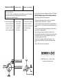
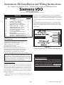
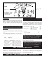
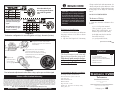
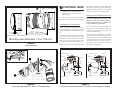
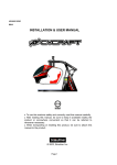
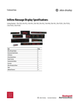
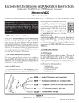
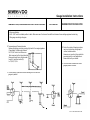
Gauge Installation Instructions TEMPERATURE, PRESSURE AND FUEL LEVEL GAUGES VOLTMETER RUDDER POSITION INDICATOR A. Disconnect battery. B. Cut 2-3/32" hole in a suitable position in dash. Make sure rear of instrument has sufficient clearance from existing equipment and wiring. C. Wire gauge according to diagram. D. Temperature and Pressure Senders Remove blind plug or existing warning light switch from engine/gearbox (If applicable). Install sender instead. Cut 2-5/16" hole in tank. Make sure float movement will not be obstructed. Remove all metal burrs. Adjust sender length (L) and float radius (R): L= 1/2 H, R" 2/3 H. D. Due to the variety of steering systems, we do not include any linkage parts without rudder senders. However, our mounting kit provides the necessary parts for most applications. Please check with your dealer. E. For dual station Installation wire two gauges parallel to sender. E. For dual station installation use dual sending unit and wire two gauges in parallel. 0-511-011-063 rev.01-05 Engine Hour Meter Quartz Clock Power Trim Gauge A. Disconnect battery. B. Cut 2 - 3/32" hole in a suitable position in dash. Make sure rear of instrument has sufficient clearance from existing equipment and wiring. C. Wire gauge according to diagram. D. Positive Gauge terminal D. Positive Gauge D. For electrical connection must be connected to Terminal must of sender unit refer to +12 V only if engine is be connected power trim manufacturer running (i.e. ignition to unswitched instruction (owners switch, pressure switch) 12 V source. manual) If you should not get proper readings from Siemens VDO Gauge: DO NOT attempt to open, as this voids any warranty! Check wiring, especially for proper ground. All gauges are floating grounds: you have to run a separate ground connection from terminal "-" to ground. If sender is standard ground, make sure the engine/gearbox has common ground, i.e. is grounded to same battery negative as gauges. In case of sender being floating ground, ground terminal has to be connected to gauge negative. Not for Voltmeter, Engine Hour Meter and Quartz Clocks: Pull sender lead from sending unit. Pointer must now move fully to one side of scale. Then, ground sender lead. Pointer must now peg to opposite side of scale. If both occurs, your gauge and wiring is basically o.k., the problem will be a defective or improperly grounded sending unit. Siemens VDO Instruments are repairable. Permanent +12V Dash Light Switch ALLENTOWN, PA USA 1-800-265-1818 http://sso-usa.siemensvdo.com/ Instrument Kit Installation and Wiring Instructions For Cockpit, Cockpit Royal, Series 1, Heritage Gold, Contour and Millennum Series Siemens VDO Allentown, Pennsylvania USA USE IS RESTRICTED TO 12 VOLT NEGATIVE GROUND ELECTRICAL SYSTEMS. Parts List Item 1. 2. 3. 4. 5. 6. 7. 8. 9 10. 11. 12. 13. 14. Description Quantity Programmable Speedometer (3 1/8" or 3 3/8" diameter) Voltmeter (2 1/16" diameter Fuel Gauge (2 1/16" diameter) Pressure Gauge (2 1/16" diameter) Temperature Gauge (2 1/16" diameter) Pressure Sender (1/8" – 27 NPT) Temperature Sender (3/8" – 18 NPT) Fuel Level Sender & Float Arm 3/8"-18 NPT to 1/2"-14 NPT adapter Speed Sensor, Hall Effect Spin-Lok Mounting Clamp for gauges and speedometer Instrument Kit Installation Instruction 2. Using a hole saw cut mounting holes in panel. All small gauges require a 2 1/16" (52mm) hole for mounting. Speedometer are 3 3/8" (85mm) or 3 1/8" (80mm) depending upon which kit you purchased. If in dout measure the back of the instrument priop to cutting any Holes. 1 1 1 1 1 1 1 1 1 1 3. Hand tighten the gauges using the spin-Loc mounting clamps until the gauge can be no longer rotated in the panel. (Note) If the gauge can not be tighten fully remove and reverse spin-loc clamp and re-install. 5 1 Speedometer Programmable Installation Instructions 1 Wire Harness (Millenimum Kit ONLY) 1 Minimum mounting depth 2 7/8" (73mm) Additional Material That Maybe Required For Installation: 16 Gauge stanard insulated wire (P/N: 240-023) Insulated female 1/4" spade terminals Gauge connectors for 2 1/16" gauge (one per gauge P/N: 240-026) Speedometer connector (P/N: 240-053) Fuel Sender Bolt on Installation Kit ( P/N: 226-451) Fuel Sender Weld on Installation Kit ( P/N: 226-901) Stud Mounting Kits 2 1/16" gauges ( P/N: 600-402) Stud Mounting Kit, Speedometer ( P/N: 600-401) Fuel Sender Ford application: 1935-1956 ( P/N: 226-902) Diagram A Proper mounting using VDOs Spin-Lok Mounting Clamp CAUTION: Read these instructions thoroughly before making installation. Do not deviate from assembly or wiring instructions. Always disconnect battery ground before making any electrical connections. If in doubt, please contact your dealer or VDO Instruments at 1-800-265-1818. General Information: These kits come with VDOs Spin-Lok Mounting Clamps for easy installation. Optional VDO mounting brackets are available from your VDO dealer, should you require them. Note that the programmable speedometer included in this kit has a special set of installation and operation instructions. These instructions must be followed carefully to insure proper performance of the speedometer. Speedometer Installation: PLEASE REFER TO THE SEPARATE PROGRAMMABLE SPEEDOMETER INSTALLATION AND OPERATING INSTRUCTIONS FOR PROPER MOUNTING AND OPERATION OF THE SPEEDOMETER. SEE PAGE 3 FOR INSTRUCTIONS ON INSTALLING SPEED SENSORS. Gauge Installation: 1. Select mounting locations for all gauges which provide good visibility for the driver. Lay out center points for each instrument on the panel. Page 1 Part #0 515 010 396 Rev. 09/03 Page 2 CAUTION: Before drilling any holes into the tank, place the sender assembly on top of the tank to judge the proper hole placementone that will allow the float arm clearance inside the tank. SAFETY PRECAUTION: When making modifications to fuel tanks, it is essential that the tank be removed from the vehicle, and that it is empty, clean and dry. After drilling, make sure all chips and other foreign matter have been removed from the tank. Clean the tank thoroughly. If no holes exist in the fuel tank (see CAUTION, above): 1. Carefully mark an area to be cut open so you can insert the sender. The key to this step is to position the float as close as possible to the center of the tank. This provides the most stable and accurate reading when the fuel sloshes back and forth. Make sure you have allowed enough clearance for the float arm before you cut the hole. Remember, you only get one chance to do it right! 2. Cut a 1.697" (43 mm) hole in the top of the tank. 3. With the gasket in place below the flange, carefully feed the float arm and sender body into the 1.697" (43 mm) hole in the tank. Make certain the float arm has free motion within the tank. Using the sender flange as a template, locate the positions of the five mounting holes. Depending on the thickness of the tank, either self-tapping screws or #8-32 machine screws may be used, drilling and tapping accordingly. If threaded holes already exist, check the thread size and use the appropriate hardware. 4. Insert the fuel sender assembly into the tank and apply gas-proof sealant. Align the holes and thread in the ½" mounting screws through the holes in the sender flange and tank. Check to make sure that all screws are secure. AVOID OVERTIGHTENING! When you have done this, the installation of the fuel level sender unit is complete. Diagram E Fuel Sender Assembly and Hole Pattern Dimensions Temperature and Pressure Sender Installation: Check the OEM engine manual for the correct location for these senders. Temperature senders are most accurate when installed in an aftermarket intake manifold. Installing the sender into the cylinder head can cause high readings due to exhaust manifold heat. NOTE: This kit contains a 3/8 " 18 NPT temperature sender, and a 3/8 " 18 NPT to ½ " 14 NPT adapter should you need it. CAUTION: Do not use tee, angle or reducing adapters for temperature senders, as the tip may not be immersed in the water flow. Do not use teflon tape on sender threads. It will interfere with the electrical ground. Senders have self-sealing, tapered pipe threads. Speed Sensor Installation: The speed sender included for use with the programmable speedometer in this VDO Instrument Kit is a standard, closed Hall-effect sender. It is a closed sender with 7/8" 18 NPT fittings for GM and many other transmissions. It sends a 16 pulse-per-revolution signal in a three-wire configuration. (A standard, through Hall-effect sender for use with cruise control is available from your VDO dealer (Part Number 340-012). Other senders which can be used with the programmable sender include Ford [through or closed] Hall-effect senders or almost any inductive sender.) 1. If you are replacing an existing speedometer: Remove the cable that went to the old speedometer. 2. Install the new sender in the place where the old cable was bolted onto the transmission. or, in a new installation: 1. Bolt the sender onto the transmission at the location specified by the OEM for speedometer cable installation. 2. Run the eight foot length of wire to the new speedometer. 3. Cut it to length, and attach it to the new speedometer according to the instructions in the separate, enclosed speedometer installation and operation instructions. Diagram F Standard, closed, 3-wire Hall-effect sender included in kit VOLTAGE W IRING OF POWER AND GROUND TO EACH GAUGE LEGEND Sender Wire: “S” or “G” Ground Wire: or 12 Volt Wire: (+) Ground Diagram G Wiring Diagram I LLUMINATION WIRING AND WIRING OF SENDERS TO EACH GAUGE Ground fuse dash light switch pressure sender temperature sender Electrical Wiring: Refer to the wiring diagram, Diagram G. Wire gauges in series from a positive (+) accessory to a source which is not already overloaded with fans, air conditioning, and such. The ground () wire is also run in series, including the light socket ground. The final ground run, using 14-gauge wire, should be connected to a good ground such as the engine block ground strap or directly to the negative battery post. III. Senders can be tested with an ohmmeter that measures from 10 Ω to 2000 Ω. Connect the positive (+) lead from the tester to the sender terminal, and the negative () lead to a good ground. The following readings should occur if the sender is operating properly: Temperature sender engine cold: engine approximately 180°: Pressure sender engine off: engine running 40 psi: engine running 60 psi: System Testing: IV. Voltmeter: 12 13.7 14.3 13.0 14.0 NOTE: These readings are approximate, depending on the regulator system and engine speed. Lower readings indicate a bad battery, regulator, or alternator; or incorrect wiring. II. Turn on the ignition key. Gauges should read: a) With the key on, pull the sender wire off of the sender: Fuel and pressure gauges: needle to the right-hand position Temperature gauge: needle to the left-hand position 700Ω 68Ω 10 Ω 105 Ω 152 Ω Volts: Key on, engine off: Engine running, no accessories or lights: Engine running with accessories, lights: I. Turn on the dash light switch to see if all gauges light up. If not, check your wiring, the ground, and all bulbs. Reconnect or replace as necessary. Pressure: Needle to 0 Fuel: Needle to amount of fuel in the tank Temperature: Needle to the temperature of the engine water fuel sender NOTE: All VDO electrical gauge pointers will peg full lefthand position when the key is off. NOTE: See the separate Speedometer Installation and Operation Instructions for information on wiring the speedometer. When installation and wiring has been completed, the following tests should be performed to ensure that all systems are functioning properly. Ground V. With VDO fuel tank senders (Part #226 001), an empty tank will read 10Ω. As fuel is added, the resistance reading will rise until the tank is full, when it will read 180 Ω. NOTE: If you already have a fuel level sender in your tank, check the resistance readings. If they do not match the readings above, VDO manufactures a number of fuel gauges which should match your sender. REMEMBER: The ohm range of the sender and the gauge MUST MATCH! b) With the key on, ground the sender wire to the engine block: Fuel and Pressure Gauges: needle to the left-hand position Temperature Gauge: needle to the right-hand position Siemens VDO Automotive Limited Warranty Siemens VDO Automotive warrants all merchandise against defects in factory workmanship and materials for a period of 24 months after purchase. This warranty applies to the first retail purchaser and covers only those products exposed to normal use or service. Provisions of this warranty shall not apply to a VDO product used for a purpose for which it is not designed, or which has been altered in any way that would be detrimental to the performance or life of the product, or misapplication, misuse, negligence or accident. On any part or product found to be defective after examination by Siemens VDO Automotive, Siemens VDO . Siemens VDO Automotive will only repair or replacethe merchandise through the oringinal dealer or on direct basis. Siemens VDO Automotive assumes no responsibility for diagnosis, removal and/or installation labor, loss of vehicla use, loss of time, inconvenience or any other consequential expenses. The warranties herin are in lieu of any other expressed or implied warranties, including any implied warranty of merchantabilty or fitness, and any other obligation on the part of Siemens VDO Automotive, or selling dealer. http://sso-usa.siemensvdo.com/. Page 4 Phone: 1-800-265-1818 ➊ Use this table if you are using your tachometer with an ignition coil. Use this table if your ignition is the type that provides a pulse-per-revolution type signal. BEGIN HERE CAUTION: Read these instructions thoroughly before making installation. Do not deviate from assembly or wiring instructions. Always disconnect battery ground before making any electrical connections. If in doubt, please contact your dealer or VDO Instruments at (800) 265-1818. Clamp over the back of the instrument. Its direction depends on the thickness of the panel (Diagram B). Tighten the clamp until the gauge can no longer be rotated by hand. DO NOT OVERTIGHTEN. Tachometer Wiring: 1. Run wires from the tachometer location to: a) A +12 volt power terminal. 4000 RPM Alternator Tach 2:1 ratio set for 6 cyl. gas; use pot to calibrate. (This positive power source MUST BE SWITCHED, and should be protected with a fuse); Tachometer Installation: Diagram D Tachometer configuration for use with ignition coil (top); alternator (bottom) 1. Select the location where you will mount the gauge, and cut a 2 ¹⁄₁₆" hole as shown in Diagram A. b) the light switch (also after the fuse in the fuse box); c) a good ground location; 2. Slip the VDO Spin-Lok Mounting ➊ Compare the VDO Tachometer [text continues at # Ë] reading with that of a reference tachometer. ➌ ➋ Adjust the potentiometer on the side of the gauge. The pointer will move clockwise or counterclockwise as you adjust. When the VDO Tachometer reading matches that of the reference tachometer, the adjustment is complete. Diagram E Fine tachometer adjustment needed when using a pulse-per-revolution signal Siemens VDO Limited Warranty VDO North America warrants all merchandise against defects in factory workmanship and materials for a period of 24 months after purchase. This warranty applies to the first retail purchaser and covers only those products exposed to normal use or service. Provisions of this warranty shall not apply to a VDO product used for a purpose for which it is not designed, or which has been altered in any way that would be detrimental to the performance or life of the product, or misapplication, misuse, negligence or accident. On any part or product found to be defective after examination by VDO North America, VDO North America will only repair or replace the merchandise through the original selling dealer or on a direct basis. VDO North America assumes no responsibility for diagnosis, removal and/or installation labor, loss of vehicle use, loss of time, inconvenience or any other consequential expenses. The warranties herin are in lieu of any other expressed or implied warranties, including any implied warranty of merchantability or fitness, and any other obligation on the part of VDO North America, or selling dealer. (NOTE: This is a Limited Warranty as defined by the Magnuson-Moss Warranty Act of 1975.) Siemens VDO http://sso-usa.siemensvdo.com Parts List CAUTION!!! The bezel diameter is only a few millimeters larger than the gauge itself. With that in mind, measure and precisely mark the gauge location before cutting any holes! Tools and Materials Needed For Installation: 16 Gauge stranded, insulated wire Non-insulated ¼" spade connectors 2 ¹⁄₁₆" hole saw Drill and drill bit set Half-round file Tape measure or ruler Small tools: wrench or nut driver, utility knife, pliers, etc. Ù Item Description Quantity 1. Tachometer (2 ¹⁄₁₆" [52 mm] diameter) 2. Lamp Socket (Push in, wedge-type) 1 3. Light Bulb (12-volt / G.E. #158 or equivalent) 1 4. VDO Spin-Lok™ Clamp 1 5. Installation Instructions 1 1 S i e m e n s ® VDO Tachometer Installation Instructions Instruction Sheet #0 515 012 044 Rev. 03/00 INSTRUCTIONS FOR THE INSTALLATION OF THE TACHOMETER ARE CONTAINED HEREIN. USE IS RESTRICTED TO 12-VOLT NEGATIVE GROUND ELECTRICAL SYSTEMS. LIGHT BULB, IF SUPPLIED, IS 12 VOLT. To Begin, go to #➊ PP PP é PP PD[ PP PP Mounting hole dimension = 2¹⁄₁₆" (52 mm) Diagram A ➋ CONTINUE HERE d) the location of the signal source (alternator, coil or other ignition signal source). 2. Connect the wiring to the appropriate tachometer terminals as shown in Diagram C. Configuring the Tachometer: Before your VDO Tachometer will function properly with your engine, you will need to configure it as shown in Diagram D. The table at the top of Diagram D shows how to set the DIP switches for use with an ignition coil; the table at the bottom shows how to set the DIP switches when using the tachometer with an alternator. When using the VDO Tachometer with Gauge dimensions another type of ignition system, determine the number of pulses per revolution the ignition signal provides, and set the DIP switches as shown in the bottom table. Adjusting the Tachometer Pointer: Use of the VDO Tachometer with an alternator or other type of ignition that provides a signal in pulses per revolution may requre calibration of the pointer. This can be done as show in Diagram E. Please note that this calibration is designed to adjust the reading between 30% and 100% of the RPM range. At this point, the installation and wiring of your new VDO Tachometer is complete. Turn on the ignition and the lights in the car and check to see that the instrument and light work properly. If they dont, recheck your wiring, referring to the wiring description in Diagram C. DQSX_]UdUb DQSX_]UdUb 7b_e^T 13DQ` 7b_e^T 7b_e^T 7b_e^T <YWXd CgYdSX DUb]Y^Q\!_b° <YWXd CgYdSX 6ecU 2_h &2,/ Mounting Nut direction depends on panel width A: B: 2QddUbi CgYdSXUT !"f 9W^YdY_^3_Y\ 2QddUbi 0 .4" (0 10 mm) .4" .8" (10 20 mm) Diagram B Proper mounting using VDOs CgYdSXUT !"f 1\dUb^Qd_b Spin-Lokä Mounting Clamp Diagram C Tachometer wiring with Alternator AC Tap (left); and with Ignition Coil (right)