1
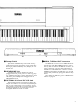
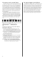
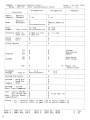
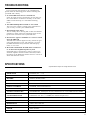
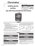
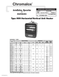
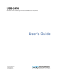
SPECIAL MESSAGE SECTION PRODUCT SAFETY MARKINGS: Yamaha electronic products may have either labels similar to the graphics shown below or molded/stamped facsimiles of these graphics on the enclosure. The explanation of these graphics appears on this page. Please observe all cautions indicated on this page and those indicated in the safety instruction section. CAUTION RISK OF ELECTRIC SHOCK DO NOT OPEN CAUTION: TO REDUCE THE RISK OF ELECTRIC SHOCK. DO NOT REMOVE COVER (OR BACK). NO USER-SERVICEABLE PARTS INSIDE. REFER SERVICING TO QUALIFIED SERVICE PERSONNEL. See bottom of Keyboard enclosure for graphic symbol markings The exclamation point with the equilateral triangle is intended to alert the user to the presence of important operating and maintenance (servicing) instructions in the literature accompanying the product. The lightning flash with arrowhead symbol within the equilateral triangle is intended to alert the user to the presence of uninsulated “dangerous voltage” within the product’s enclosure that may be of sufficient magnitude to constitute a risk of electrical shock. IMPORTANT NOTICE: All Yamaha electronic products are tested and approved by an independent safety testing laboratory in order that you may be sure that when it is properly installed and used in its normal and customary manner, all foreseeable risks have been eliminated. DO NOT modify this unit or commission others to do so unless specifically authorized by Yamaha. Product performance and/or safety standards may be diminished. Claims filed under the expressed warranty may be denied if the unit is/has been modified. Implied warranties may also be affected. SPECIFICATIONS SUBJECT TO CHANGE: The information contained in this manual is believed to be correct at the time of printing. However, Yamaha reserves the right to change or modify any of the specifications without notice or obligation to update existing units. ENVIRONMENTAL ISSUES: Yamaha strives to produce products that are both user safe and environmentally friendly. We sincerely believe that our products and the production methods used to produce them, meet these goals. In keeping with both the letter and the spirit of the law, we want you to be aware of the following: Battery Notice: This product MAY contain a small nonrechargeable battery which (if applicable) is soldered in place. The average life span of this type of battery is approximately five years. When replacement becomes necessary, contact a qualified service representative to perform the replacement. Warning: Do not attempt to recharge, disassemble, or incinerate this type of battery. Keep all batteries away from children. Dispose of used batteries promptly and as regulated by applicable laws. Note: In some areas, the servicer is required by law to return the defective parts. However, you do have the option of having the servicer dispose of these parts for you. Disposal Notice: Should this product become damaged beyond repair, or for some reason its useful life is considered to be at an end, please observe all local, state, and federal regulations that relate to the disposal of products that contain lead, batteries, plastics, etc. NOTICE: Service charges incurred due to lack of knowledge relating to how a function or effect works (when the unit is operating as designed) are not covered by the manufacturer’s warranty, and are therefore the owners responsibility. Please study this manual carefully and consult your dealer before requesting service. NAME PLATE LOCATION: The graphic below indicates the location of the name plate. The model number, serial number, power requirements, etc., are located on this plate. You should record the model number, serial number, and the date of purchase in the spaces provided below and retain this manual as a permanent record of your purchase. Model _____________________________________ Serial No. __________________________________ Purchase Date _____________________________ 92-469-q CONTENTS KEYBOARD STAND ASSEMBLY ......................... 2 TRANSPOSITION ................................................. 7 THE CONTROLS AND CONNECTORS ................. 4 PITCH CONTROL ................................................. 7 LISTEN TO THE DEMONSTRATION.................... 6 MIDI FUNCTIONS ................................................ 8 PLAYING THE PDP-300 ...................................... 6 MIDI DATA FORMAT ......................................... 11 DUAL MODE ........................................................ 7 TROUBLESHOOTING ......................................... 13 TOUCH SENSITIVITY .......................................... 7 SPECIFICATIONS............................................... 13 TAKING CARE OF YOUR PDP-300 PREPARATION Your PDP-300 is a fine musical instrument, and deserves the most careful treatment. Observe the following points and your PDP-300 will sound and look great for many years. 1. Never open the case and touch or tamper with the internal circuitry. • Check your power supply Make sure that your local AC mains voltage matches the voltage specified on the name plate on the bottom panel. Make sure that the voltage selector is set for the voltage in your area. 2. Always turn the POWER switch OFF after use, and cover the instrument with the dust cover provided. 3. Clean the cabinet and keys of your PDP-300 only with a clean, slightly damp cloth. A neutral cleanser may be used if desired. Never use abrasive cleansers, waxes, solvents or chemical dust cloths since these can dull or damage the finish. 4. Never place any vinyl products on your PDP-300. Contact with vinyl can cause irreversible damage to the finish. 5. Install your PDP-300 in a place that is away from direct sunlight, excessive humidity or heat. 6. Never apply excessive force to the controls, connectors or other parts of your PDP-300, and avoid scratching or bumping it with hard objects. • The music stand If you will be using sheet music with your PDP-300, raise the music stand built into it’s top panel by lifting the rear edge of the music stand until it clicks into place. The music stand can be lowered after slightly lifting the stand and pressing the two brackets which support it inward. FCC INFORMATION (U.S.A.) 1. IMPORTANT NOTICE: DO NOT MODIFY THIS UNIT! This product, when installed as indicated in the instructions contained in this manual, meets FCC requirements. Modifications not expressly approved by Yamaha may void your authority, granted by the FCC, to use the product. 2. IMPORTANT : When connecting this product to accessories and/or another product use only high quality shielded cables. Cable/s supplied with this product MUST be used. Follow all installation instructions. Failure to follow instructions could void your FCC authorization to use this product in the USA. 3. NOTE: This product has been tested and found to comply with the requirements listed in FCC Regulations, Part 15 for Class “B” digital devices. Compliance with these requirements provides a reasonable level of assurance that your use of this product in a residential environment will not result in harmful interference with other electronic devices. This equipment generates/uses radio frequencies and, if not installed and used according to the instructions found in the users manual, may cause interference harmful to the operation of other electronic devices. Compliance with FCC regulations does not guarantee that interference will not occur in all installations. If this product is found to be the source of interference, which can be determined by turning the unit “OFF” and “ON”, please try to eliminate the problem by using one of the following measures: Relocate either this product or the device that is being affected by the interference. Utilize power outlets that are on different branch (circuit breaker or fuse) circuits or install AC line filter/s. In the case of radio or TV interference, relocate/reorient the antenna. If the antenna lead-in is 300 ohm ribbon lead, change the lead-in to co-axial type cable. If these corrective measures do not produce satisfactory results, please contact the local retailer authorized to distribute this type of product. If you can not locate the appropriate retailer, please contact Yamaha Corporation of America, Electronic Service Division, 6600 Orangethorpe Ave, Buena Park, CA90620 The above statements apply ONLY to those products distributed by Yamaha Corporation of America or its subsidiaries. * This applies only to products distributed by YAMAHA CORPORATION OF AMERICA. 1 3 1 C D D E E A B C D E Main unit Center panel Pedal box Side panels Base boards • Short large-head screws (black) • Long screws (gold) x 4 4 • Short large-head screws (black) x 4 • Long screws (black) x 4 C B D D E • The protruding sections of the metal brackets at each end of the center panel must face upward. • Short screws (black) x 4 • Joint connectors x 4 • Long screws (black) 2 KEYBOARD STAND ASSEMBLY • Joint connectors Note: We do not recommend attempting to assemble the PDP300 alone. The job can be easily accomplished, however, with only two people. z Open the box and remove all the parts. D D E E On opening the box you should find the parts shown in the illustration to the above. Check to make sure that all the required parts are provided. the side panels (D) and base x Assemble boards (E). Install the joint connectors in side panels (D) as shown in the illustration, then secure the base boards (E) to the side panels (D) with the long gold-colored screws. • Long screws (gold) 2 * When installing the joint connectors in the holes in the side panels (D), make sure that the arrows printed on their upper surface face in the direction shown in the illustration. * Make sure that the left and right base boards are facing in the proper direction as shown in the illustration. The grooved edge of each base board should face inward. 5 A A B C D D D E E • Insert the screws extending from the bottom of the main unit into the bracket grooves. • Short screws (black) 6 7 • Cord holders • Rotate the adjuster unit it coms in firm contact with the floor surface. the side panels (D) to the pedal c Attach box (C). n Connect the pedal cords. Attach the center panel (B) to the side v panels (D). The center panel (B) is installed between the side pan- * Check to make sure that all screws have been securely tightened. Place the pedal box on top of the brackets attached to the side panels (D), and attach using the four short largehead black-colored screws. els (D) with the center lug on each end closer to the pedal side of the pedal box. Each side of the center panel is attached using two long black screws. b Install the main unit (A). Place the main unit on the side panels (D) with the screws on its bottom panel (toward the rear of the main unit) just behind the grooves in the brackets located at the top of the side panels (D), then slide the keyboard forward until it stops. Align the holes on the bottom panel of the main unit (A) with the holes in the brackets on the side panels (D), then screw in and securely tighten the four short blackcolored screws. Attach the pedal cord to the two pedal cord holders located on the side panel, then insert the pedal cord plug into the connector located at the bottom of the main unit’s rear panel, making sure that the tab on the plug faces forward. m Be sure to set the adjuster. For stability, an adjuster is provided on the bottom of the pedal box (C). Rotate the adjuster until it comes in firm contact with the floor surface. The adjuster ensures stable pedal operation and facilitates pedal effect control. * If the adjuster is not in firm contact with the floor surface, distorted sound may result. 3 THE CONTROLS AND CONNECTORS q [POWER] Switch Press the [POWER] switch once to turn the power ON, a second time to turn the power OFF. When the power is initially turned ON, the PIANO 1 voice selector LED will light. w [MASTER VOLUME] Control The [MASTER VOLUME] control adjusts the volume (level) of sound produced by the PDP-300. The [MASTER VOLUME] control also adjusts headphone volume when a pair of headphones is plugged into the HEADPHONE jack i. e [REVERB] Button The [REVERB] button selects a number of digital effects that you can use for extra depth and expressive power. To select an effect press the [REVERB] button a few times until the indicator corresponding to the desired effect lights (the indicators light in sequence each time the [REVERB] button is pressed). No effect is produced when all indicators are off. PEDAL When the PEDAL indicator is lit, a subtle but warm reverb effect is added to the sound whenever the damper pedal is pressed. ROOM This setting add a continuous reverb effect to the sound that is similar to the type of acoustic reverberation you would hear in a medium-size room. HALL For a really spacious reverb sound, use the HALL setting. This effect simulates the natural reverberation of a large concert hall. Note: When the [POWER] switch is initially turned ON all reverb effects are turned OFF. r [MIDI/TRANSPOSE] Button The [MIDI/TRANSPOSE] button allows access to the PDP-300’s TRANSPOSE function (to shift the pitch of the entire keyboard up or down) and MIDI functions. For details refer to the “TRANSPOSITION” and “MIDI FUNCTIONS” sections on pages 7 and 8, respectively. t Voice Selectors The PDP-300 has six voice selectors. Simply press any of the voice selectors to select the corresponding voice. The LED indicator above the voice selector will light to indicate which voice is currently selected. The PDP-300 also has a DUAL mode in which two voices can be played simultaneously across the full range of the keyboard — see page 7 for details. Note: The PIANO 1 voice is automatically selected whenever the [POWER] switch is initially turned ON. 4 y Soft/Sostenuto Pedal This pedal has two distinct modes — “soft” and “sostenuto” — which can be selected as required. The Soft Mode This is the normal mode for the Soft/Sostenuto pedal, and is automatically selected when the power is initially turned ON. In this mode, pressing the pedal reduces the volume and slightly changes the timbre of notes played. The Sostenuto Mode From the normal Soft mode, the Sostenuto mode can be selected by holding down the [MIDI/ TRANSPOSE] button r and pressing the Soft/ Sostenuto pedal once. In the sostenuto mode, if you play a note or chord on the keyboard and press the pedal while the note(s) are held, those notes will be sustained as long as the pedal is held (as if the damper pedal had been pressed) but all subsequently played notes will not be sustained. This makes it possible to sustain a chord, for example, while other notes are played “staccato.” From the Sostenuto mode it is possible to return to the Soft pedal mode by holding down the [MIDI/ TRANSPOSE] button and pressing the Soft/Sostenuto pedal. u Damper Pedal The damper pedal functions in the same way as a damper pedal on an acoustic piano. When the damper pedal is pressed notes played have a long sustain. Releasing the pedal immediately stops (damps) any sustained notes. i HEADPHONE Jack A standard pair of stereo headphones can be plugged in here for private practice or late-night playing. The internal speaker system is automatically shut off when a pair of headphones is plugged into the HEADPHONE jack. !00 MIDI IN, THRU and OUT Connectors The MIDI IN connector receives MIDI data from an external MIDI device which can be used to control the PDP-300. The MIDI THRU connector re-transmits any data received at the MIDI IN connector, allowing “chaining” of several MIDI instruments or other devices. The MIDI OUT connector transmits MIDI data generated by the PDP-300 (e.g. note and velocity data produced by playing the PDP-300 keyboard). More details on MIDI are given in “MIDI FUNCTIONS” on page 8. o OPTIONAL IN L/R and OUT L/R Jacks The Optional Out jacks can be used to deliver the output of the PDP-300 to an external keyboard amplifier or stereo sound system. On the contrary, the Optional In jacks can be used to reproduce the output of another instrument such as cassette tape recorder through the PDP-300’s built in speaker. 5 LISTEN TO THE DEMONSTRATION The PDP-300 is programmed to automatically play two demonstration tunes to give you a sample of their superb sound. 1. Impromptus Op. 142-3 (F. Schubert) 2. West Coast (Original) The demonstration tunes can be selected and played by pressing the C7 key (the highest key on the keyboard) while holding the [MIDI/TRANSPOSE] button. Hold [MIDI/TRANSPOSE] and press the C7 key once to hear the first demonstration tune, twice to hear the second tune. Pressing the C7 key more than twice in the PDP-300 causes all the demo tunes to be played in sequence and repeated until the demonstration is stopped by pressing the [MIDI/TRANSPOSE] button again. PLAYING THE PDP-300 After making sure that the PDP-300’s AC plug is properly inserted into a convenient AC wall outlet: 1. Press the [POWER] switch located to the left of the keyboard to turn the power ON. When the power is turned ON, the [PIANO 1] voice selector LED will light (the PIANO 1 voice is automatically selected whenever the power is turned ON). 2. Initially set the [MASTER VOLUME] control about three quarters of the way towards the “MAX” setting. Then, when you start playing, adjust the [MASTER VOLUME] control for the most comfortable listening level. 3. Select the desired voice by pressing one of the voice selectors. 4. Play. All voices except CLAVINOVA TONE have 16note polyphony. The CLAVINOVA TONE voice has 8-note polyphony. The PDP-300 also offers keyboard touch response, so the volume and timbre of notes played can be controlled according to how “hard” you play the keys. The amount of variation available depends on the selected voice. 5. You can also add REVERB effects as desired by using the [REVERB] button. (see “THE CONTROLS AND CONNECTORS” on page 4.) 6 DUAL MODE TRANSPOSITION The DUAL mode makes it possible to play two voices simultaneously across the entire range of the keyboard. To activate the DUAL mode simply press two voice selectors at the same time — or press one voice selector while holding another. The voice indicators of both selected voice will light when the DUAL mode is active. To return to the normal single-voice play mode, press any single voice selector. Please note that if both voice selectors are pressed simultaneously, both voices will be produced at the same volume. It is possible to change the balance between the two voices, however, by pressing and holding one voice selector before pressing the other. The voice corresponding to the voice selector pressed first will be reproduced at a slightly louder volume than the second voice. Polyphony in the DUAL mode is as follows: The Transposition function makes it possible to shift the pitch of the entire keyboard up or down in semitone intervals up to a maximum of six semitones. “Transposing” the pitch of the PDP-300 keyboard makes it easier to play in difficult key signatures, and you can simply match the pitch of the keyboard to the range of a singer or other instrumentalist. The [MIDI/TRANSPOSE] button and keys F # 5 through F#6 on the keyboard are used for transposition. 1. Press and hold the [MIDI/TRANSPOSE] button. 2. Press a key between F #5 and F#6 according to the desired amount of transposition.* 3. Release the [MIDI/TRANSPOSE] button. Notes/voice Polyphony 16 + 16 8 8 + 16 5 * Pressing the C6 key produces normal keyboard pitch. Pressing the key to the left of C6 (B5) transposes the pitch of the keyboard down a semitone, the next key to the left (B b 5) transposes down a whole tone (two semitones), etc., down to the F#5 key which transposes down 6 semitones. Upward transposition is accomplished in the same way using the keys to the right of C6, up to F #6 which transposes up 6 semitones. Note: The normal keyboard pitch is automatically selected when the power is turned ON. TOUCH SENSITIVITY PITCH CONTROL The PDP-300 can be set to one of three different types of keyboard touch sensitivity — HARD, MEDIUM or SOFT — to match different playing styles and preferences. The HARD setting requires the keys to be played quite hard to produce maximum loudness. The MEDIUM setting produces a fairly “standard” keyboard response. This setting is automatically selected whenever the power is turned ON. The SOFT setting allows maximum loudness to be produced with relatively light key pressure. To select a touch sensitivity setting hold the [MIDI/ TRANSPOSE] button and press the [REVERB] button a few times until the REVERB indicator corresponding to the desired setting lights: Pitch control makes it possible to tune the PDP-300 over a ±50-cent range in approximately 1.2-cent intervals. A hundred “cents” equals one semitone, so the tuning range provided allows fine tuning of overall pitch over a range of approximately a semitone. Pitch control is useful for tuning the PDP-300 to match that of other instruments or recorded music. PEDAL = HARD ROOM = MEDIUM HALL = SOFT Tuning Up 1. To tune up (raise pitch), hold the A-1 and B-1 keys simultaneously. 2. Press any key between C3 and B3. Each time a key in this range is pressed the pitch is increased by approximately 1.2 cents, up to a maximum of 50 cents above standard pitch. 3. Release the A-1 and B-1 keys. Tuning Down 1. To tune down (lower pitch), hold the A-1 and A #-1 keys simultaneously. 2. Press any key between C3 and B3. Each time a key in this range is pressed the pitch is decreased by approximately 1.2 cents, up to a maximum of 50 cents below standard pitch. 3. Release the A-1 and A#-1 keys. To Restore Standard Pitch* 1. To restore standard pitch (A3 = 440 Hz), hold the A-1, A#-1 and B-1 keys simultaneously. 2. Press any key between C3 and B3. 3. Release the A-1, A#-1 and B-1 keys. * Standard pitch (A3 = 440 Hz) is automatically set whenever the [POWER] switch is turned ON. For Pitch Control (A-1 + B-1/A-1 + A # -1) For Pitch Control (C3 ~ B3) For Transposition (F#5 ~ F#6) 7 MIDI FUNCTIONS Control Change Numbers A Brief Introduction to MIDI MIDI, the Musical Instrument Digital Interface, is a world-standard communication interface that allows MIDI-compatible musical instruments and equipment to share musical information and control one another. This makes it possible to create “systems” of MIDI instruments and equipment that offer far greater versatility and control than is available with isolated instruments. For example, most MIDI keyboards transmit note and velocity (touch response) information via the MIDI OUT connector whenever a note is played on the keyboard. If the MIDI OUT connector is connected to the MIDI IN connector of a second keyboard (synthesizer, etc.) or a tone generator, the second keyboard or tone generator will respond precisely to notes played on the original transmitting keyboard. The result is that you can effectively play two instruments at once, providing thick multi-instrument sounds. This same type of musical information transfer is used for MIDI sequence recording. A sequencer can be used to “record” MIDI data received from PDP-300, for example. When the recorded data is played back, the PDP300 automatically “plays” the recorded performance in precise detail. MIDI Transmit & Receive Channel Selection The MIDI information (messages) transmitted and received by the PDP-300 is as follows: The MIDI system allows transmission and reception of MIDI data on 16 different channels. Multiple channels have been implemented to allow selective control of certain instruments or devices connected in series. For example, a single MIDI sequencer could be used to “play” two different instruments or tone generators. One of the instruments or tone generators could be set to receive only on channel 1, while the other is set to receive on channel 2. In this situation the first instrument or tone generator will respond only to channel-1 information transmitted by the sequencer, while the second instrument or tone generator will respond only to channel-2 information. This allows the sequencer to “play” two completely different parts on the receiving instruments or tone generators. In any MIDI control setup, the MIDI channels of the transmitting and receiving equipment must be matched for proper data transfer. An “OMNI” receive mode is also available, which allows reception on all 16 MIDI channels. In the OMNI mode it is not necessary to match the receive channel of the receiving device to the the transmit channel of the transmitting device (except when receiving mode messages). Note and Velocity Data Setting the MIDI Channels Note: Always use a high-quality MIDI cable to connect MIDI OUT to MIDI IN terminals. Never use MIDI cables longer than about 15 meters, since cables longer than this can pick up noise which can cause data errors. MIDI “Messages” Transmitted & Received by the PDP-300 This information tells the receiving keyboard or tone generator to play a certain note (specified by the MIDI note number) at a certain dynamic level (specified by the MIDI velocity value). Note and velocity data is transmitted by the PDP-300 whenever a key is pressed, and the PDP-300’s internal AWM tone generator will “play” the corresponding note(s) whenever note and velocity data is received from an external MIDI device. Program Change Numbers The PDP-300 transmits a MIDI program number between 0 and 5 when one of its voice selectors is pressed. This normally causes the correspondingly numbered voice or program to be selected on a receiving MIDI device. The PDP-300 will respond in the same way, automatically selecting the appropriate voice when a MIDI program change number is received. See “Program Change ON/OFF” on page 9 for information on turning program change number reception and transmission ON or OFF. For setting the transmit channel. (C1 ~ D # 2) 8 Control Change data representing Soft/Sostenuto and Damper pedal operations is transmitted by the PDP-300 whenever one of these pedals is used. If the receiving device is a tone generator or another keyboard, it will respond in the same way as the PDP-300’s internal tone generator when one of the pedals is used. The PDP-300 also receives and responds to the appropriate control change data. See “Control Change ON/OFF” on page 9 for information on turning control change number reception and transmission ON or OFF. 1. Press and hold the [MIDI/TRANSPOSE] button. 2. Press the key on the keyboard corresponding to the desired MIDI transmit or receive channel.* 3. Release the [MIDI/TRANSPOSE] button. * Keys C1 through D ヲ2 on the keyboard are used to set the MIDI transmit channel, and keys C3 through D #4 are used to turn the OMNI mode OFF and set the MIDI receive channel as shown in the illustration below. The E4 key sets the OMNI receive mode and basic receive channel 1. Note: When the power is initially turned ON, MIDI receive is set to the OMNI mode and the transmit channel is set to 1. For setting the receive channel. (C3 ~ D # 4) MIDI FUNCTION CHART Function Voice Selector* Local ON/OFF [PIANO 1] Program Change ON/OFF [PIANO 2] Control Change ON/OFF [CLAVINOVA TONE] Multi-Timbre Mode [E.PIANO] Split & Left Local OFF [HARPSICHORD] Split & Right Local OFF [ORGAN] * The MIDI functions listed above are engaged by holding down the [MIDI/TRANSPOSE] button and pressing the corresponding voice selector. Full details are given in the following pages. Local Control ON/OFF “Local Control” refers to the fact that, normally, the PDP-300 keyboard controls its internal tone generator, allowing the internal voices to be played directly from the keyboard. This situation is “Local Control ON” since the internal tone generator is controlled locally by its own keyboard. Local control can be turned OFF, however, so that the PDP-300 keyboard does not play the internal voices, but the appropriate MIDI information is still transmitted via the MIDI OUT connector when notes are played on the keyboard. At the same time, the internal tone generator responds to MIDI information received via the MIDI IN connector. This means that while an external MIDI sequencer plays the PDP300’s internal voices, an external tone generator can be played from the PDP-300’s keyboard. Turning Local Control ON or OFF 1. Hold down the [MIDI/TRANSPOSE] button. 2. Press the [PIANO 1] voice selector. If the PIANO 1 LED is lit when the [PIANO 1] voice selector is pressed, you have turned local control OFF. If the PIANO 1 LED is not lit when the [PIANO 1] voice selector is pressed, you have turned local control ON. 3. Release the [MIDI/TRANSPOSE] button. Control Change ON/OFF Normally the PDP-300 will respond to MIDI control change data received from an external MIDI device or keyboard, causing the selected PDP-300 voice to be affected by pedal and other “control” settings received from the controlling device. The PDP-300 also transmits MIDI control change information when either of its pedals are operated. This function makes it possible to cancel control change data reception and transmission if you do not want the PDP300 voices to be affected by control change data received from an external device or vice versa. 1. Hold down the [MIDI/TRANSPOSE] button. 2. Press the [CLAVINOVA TONE] voice selector. If the CLAVINOVA TONE LED is lit when the [CLAVINOVA TONE] voice selector is pressed, you have turned control change reception/transmission OFF. If the CLAVINOVA TONE LED is not lit when the [CLAVINOVA TONE] voice selector is pressed, you have turned control change reception/transmission ON. 3. Release the [MIDI/TRANSPOSE] button. The Multi-Timbre Mode The Multi-Timbre mode is a special mode in which the PDP-300 voices can be independently controlled on different MIDI channel numbers by an external MIDI device. The Multi-Timbre mode can be activated as follows: 1. Hold down the [MIDI/TRANSPOSE] button. 2. Press the [E.PIANO] voice selector. If the E.PIANO LED is lit when the [E.PIANO] voice selector is pressed, you have turned the Multi-Timbre mode ON. If the E.PIANO LED is not lit when the [E.PIANO] voice selector is pressed, you have turned the MultiTimbre mode OFF. 3. Release the [MIDI/TRANSPOSE] button. Here’s an example of how you could use the MultiTimbre mode to record three different parts on a sequencer that will play different voices on the PDP-300 when played back. 1. Connect a sequencer to the PDP-300 as shown below. Program Change ON/OFF Normally the PDP-300 will respond to MIDI program change numbers received from an external keyboard or other MIDI device, causing the correspondingly numbered PDP-300 voice to be selected. The PDP-300 will normally also send a MIDI program change number whenever one of its voices is selected, causing the correspondingly numbered voice or program to be selected on the external MIDI device if the device is set up to receive and respond to MIDI program change numbers. This function makes it possible to cancel program change number reception and transmission so that voices can be selected on the PDP-300 without affecting the external MIDI device, and vice versa. 1. Hold down the [MIDI/TRANSPOSE] button. 2. Press the [PIANO 2] voice selector. If the PIANO 2 LED is lit when the [PIANO 2] voice selector is pressed, you have turned program change reception/ transmission OFF. If the PIANO 2 LED is not lit when the [PIANO 2] voice selector is pressed, you have turned program change reception/transmission ON. 3. Release the [MIDI/TRANSPOSE] button. MIDI MIDI MIDI MIDI OUT IN OUT IN Sequencer PDP-300 2. Select the first voice and MIDI transmit channel number, then record the first part on the sequencer. 3. Activate the PDP-300 Multi-Timbre mode, then select a new MIDI transmit channel and voice and record the second part on the sequencer using its overdubbing function. 4. While still in the Multi-Timbre mode, select the third MIDI transmit channel and voice and record the third part on the sequencer using its overdubbing function. 5. Still in the Multi-Timbre mode, play back the sequencer. The recorded parts will be played back using the individual voices selected during recording, providing a full ensemble sound. 9 The Split & Left Local OFF Mode The Split & Right Local Off Mode In the split mode one section of the PDP-300 keyboard is used to play a PDP-300 voice in the normal way, while the remaining section is used to play a second MIDI keyboard or tone generator. In this mode the right-hand section of the keyboard is used to play an internal PDP-300 voice, while the left-hand section of the keyboard plays the external keyboard or tone generator. Playing the lefthand section of the keyboard produces no sound from the PDP-300. The “split point,” or the key that divides the left- and right-hand sections of the keyboard can be set at any desired key. The split mode is useful if, for example, you want to play a piano voice with the right hand while playing a synthesizer bass line or string section with the left hand. When the split mode is activated, notes played on the left-hand section are transmitted via the PDP-300 MIDI OUT connector on MIDI channel 2. Notes played on the right-hand section are transmitted on the “basic channel”. In the PDP-300 either the right- or left-hand section of the keyboard can be assigned to control an external keyboard or tone generator. Assigning the left-hand section to external tone generator control was described in the previous section. To assign the right-hand section to external tone generator control while playing the PDP-300 voices with the left hand, press the [ORGAN] voice selector instead of the [HARPSICHORD] voice selector when activating the Split mode (See “Activating the Split & Left Local OFF Mode & Selecting the Split Point” in the previous section). All other operations are exactly the same as described in the previous section. Split point set at F ヲ 2 Left-hand section plays an external device's bass voice. Right-hand section plays a PDP-300 piano voice. Activating the Split & Left Local OFF Mode & Selecting the Split Point 1. Hold down the [MIDI/TRANSPOSE] button, then press and hold down the [HARPSICHORD] voice selector. The HARPSICHORD LED indicator will flash. 2. Press the key on the keyboard at which you wish to set the split point. The HARPSICHORD LED will light continuously. The split-point key becomes the first key of the left-hand section. 3. Release the split point key. 4. Release the [MIDI/TRANSPOSE] button and [HARPSICHORD] voice selector. 5. To return to the normal full-keyboard mode, hold the [MIDI/TRANSPOSE] button and press the [HARPSICHORD] voice selector, then release both buttons. Note: When the power is initially turned ON the default split point key — F # 2 — will be automatically selected. If a new split point is selected it remains active until the power is turned OFF or a different split point is selected. 10 MIDI DATA FORMAT If you’re already very familiar with MIDI, or are using a computer to control your music hardware with computer-generated MIDI messages, the data provided in this section can help you to control the PDP-300. 1. NOTE ON/OFF Data format: [9xH] -> [kk] -> [vv] 9xH = Note ON/OFF event (x = channel number) kk = Note number (21 ~ 108 = A-1 ~ C7) vv = Velocity (Key ON = 1 ~ 127. Key OFF = 0) * Note OFF event format [8xH] -> [kk] also recognized. 2. CONTROL CHANGE & MODE MESSAGES Data format: [BxH] -> [cc] -> [dd] BxH = Control event (x = channel number) cc = Control number (or mode message number) dd = Control value cc 07H 0BH 40H 42H 43H 79H 7AH 7BH 7CH 7DH PARAMETER Volume dd 00000000 = -∞; 01101111 = -3 dB; 01111111 = ±0 dB Expression 00000000 = -∞; 01101111 = -3 dB; 01111111 = ±0 dB Damper pedal 0 ~ 3FH = OFF; 40H ~ 7FH = ON Sostenuto pedal 0 ~ 3FH = OFF; 40H ~ 7FH = ON Soft pedal 0 ~ 3FH = OFF; 40H ~ 7FH = ON Reset all controllers 0 Local ON/OFF 0 = OFF; 7FH = ON All notes OFF 0 OMNI OFF/All notes OFF 0 OMNI ON/All notes OFF 0 * 79H, 7AH, 7BH, 7CH and 7DH are receive only. 3. PROGRAM CHANGE Data format: [CxH] -> [dd] CxH = program event (x = channel number) dd = Program number dd VOICE selector 00H PIANO 1 01H PIANO 2 02H CLAVINOVA TONE 03H E.PIANO 04H HARPSICHORD 05H ORGAN 5. SYSTEM EXCLUSIVE MESSAGES Data format : [F0H] -> [43H] -> [nx] -> [ff] . . . [F7H] n = 0, ff = 7CH: Panel data reception. Panel data follows 7CH. n = 2, ff = 7CH: Panel data transmitted when this data received. n = 2, ff = 7DH: Model ID code transmitted when this data received. * Panel data is comprised of the selected voice number and reverb setting in the PDP-300. 6. MULTI TIMBRE MODE Data format: [F0H] -> [43H] -> [73H] -> [24H] -> [nnH] -> [F7H] 43H = YAMAHA ID 73H = Model ID 24H nn = 15H: MULTI TIMBRE mode ON; nn = 13H: MULTI TIMBRE mode OFF 7. SPECIAL FUNCTIONS Data format: [F0H] -> [43H] -> [73H] -> [24H] -> [11H] -> [0x] -> [cc] -> [dd] -> [F7H] 43H = YAMAHA ID 73H 24H = Model ID 11H = Special function code 0x = Control MIDI Channel cc CONTROL dd 59H REVERB 00H = OFF 01H = PEDAL 02H = ROOM 03H = HALL 5AH DUAL 00H = OFF 01H = DUAL 5BH TOUCH SENSE 00H = MEDIUM 01H = SOFT 02H = HARD 5CH 2nd VOICE NUMBER 00H ~ 05H * In the MULTI TIMBRE mode REVERB affects all voices and is received on the basic receive channel. • All MIDI data available for general use are given above. * No voice change is made when dd > 05H. 4. SYSTEM REALTIME MESSAGES Active Sensing (FEH) Transmitted every 200 milliseconds. If not received for more than 400 milliseconds a NOTE OFF occurs. 11 TROUBLESHOOTING If you encounter what appears to be a malfunction, please check the following points before assuming that your PDP-300 is faulty. 1. No Sound When the Power is Turned ON Is the AC plug properly connected to an AC wall outlet? Check the AC connection carefully. Is the VOLUME control turned up to a reasonable listening level? 2. The PDP-300 Reproduces Radio or TV Sound This can occur if there is a high-power transmitter in your vicinity. Contact your Yamaha dealer. 3. Intermittent Static Noise This is usually due to turning ON or OFF a household appliance or other electronic equipment which is fed by the same AC mains line as your PDP-300. 4. Interference Appears On Radio or TV Sets Located Near the PDP-300 The PDP-300 contains digital circuitry which can generate radio-frequency noise. The solution is to move the PDP-300 further away from the affected equipment, or vice versa. 5. Distorted Sound When the PDP-300 is Connected to An External Amplifier/Speaker System If the PDP-300 is connected to a stereo system or instrument amplifier and the sound is distorted, reduce the setting of the PDP-300 volume control to a level at which the distortion ceases. SPECIFICATIONS * Specifications subject to change without notice. KEYBOARD 88 KEYS (A-1 — C7) VOICE SELECTORS PIANO 1/2, CLAVINOVA TONE, E.PIANO, HARPSICHORD, ORGAN REVERB PEDAL, ROOM, HALL TOUCH SEVSITIVITY HARD, MEDIUM, SOFT PLAY MODES NORMAL, DUAL PEDAL CONTROLS DAMPER, SOFT/SOSTENUTO OTHER CONTROLS MASTER VOLUME, MIDI/TRANSPOSE JACKS/CONNECTORS HEADPHONES, OPTIONAL IN L/R, OPTIONAL OUT L/R, MIDI IN/OUT/THRU INPUT &OUTPUT LEVEL/IMPEDANCE OPTIONAL OUT: 600 Ω/1~4 Vpp OPTIONAL IN: 22 k Ω/-10 dBm (for nominal output level) MAIN AMPLIFIERS 15 W x 2 SPEAKERS 16 cm x 2 DIMENSIONS 1418 x 467 x 804 mm WEIGHT 46.0 kg (101.4 lbs.) FINISH Black metallic INCLUDED ACCESSORIES Dust cover, Bench 13 IMPORTANT SAFETY INSTRUCTIONS INFORMATION RELATING TO PERSONAL INJURY, ELECTRICAL SHOCK, AND FIRE HAZARD POSSIBILITIES HAS BEEN INCLUDED IN THIS LIST. WARNING- When using any electrical or electronic product, basic precautions should always be followed. These precautions include, but are not limited to, the following: 1. Read all Safety Instructions, Installation Instructions, Special Message Section items, and any Assembly Instructions found in this manual BEFORE marking any connections, including connection to the main supply. 2. Main Power Supply Verification: Yamaha products are manufactured specifically for the supply voltage in the area where they are to be sold. If you should move, or if any doubt exists about the supply voltage in your area, please contact your dealer for supply voltage verification and (if applicable) instructions. The required supply voltage is printed on the name plate. For name plate location, please refer to the graphic found in the Special Message Section of this manual. 3. This product may be equipped with a polarized plug (one blade wider than the other). If you are unable to insert the plug into the outlet, turn the plug over and try again. If the problem persists, contact an electrician to have the obsolete outlet replaced. Do NOT defeat the safety purpose of the plug. 4. Some electronic products utilize external power supplies or adapters. Do NOT connect this type of product to any power supply or adapter other than one described in the owners manual, on the name plate, or specifically recommended by Yamaha. 5. WARNING: Do not place this product or any other objects on the power cord or place it in a position where anyone could walk on, trip over, or roll anything over power or connecting cords of any kind. The use of an extension cord is not recommended! If you must use an extension cord, the minimum wire size for a 25' cord (or less) is 18 AWG. NOTE: The smaller the AWG number, the larger the current handling capacity. For longer extension cords, consult a local electrician. 8. This product was NOT designed for use in wet/damp locations and should not be used near water or exposed to rain. Examples of wet/damp locations are; near a swimming pool, spa, tub, sink, or wet basement. 9. This product should be used only with the components supplied or; a cart, rack, or stand that is recommended by the manufacturer. If a cart, rack, or stand is used, please observe all safety markings and instructions that accompany the accessory product. 10. The power supply cord (plug) should be disconnected from the outlet when electronic products are to be left unused for extended periods of time. Cords should also be disconnected when there is a high probability of lightening and/or electrical storm activity. 11. Care should be taken that objects do not fall and liquids are not spilled into the enclosure through any openings that may exist. 12. Electrical/electronic products should be serviced by a qualified service person when: a. The power supply cord has been damaged; or b. Objects have fallen, been inserted, or liquids have been spilled into the enclosure through openings; or c. The product has been exposed to rain; or d. The product dose not operate, exhibits a marked change in performance; or e. The product has been dropped, or the enclosure of the product has been damaged. 13. Do not attempt to service this product beyond that described in the user-maintenance instructions. All other servicing should be referred to qualified service personnel. 14. 6. Ventilation: Electronic products, unless specifically designed for enclosed installations, should be placed in locations that do not interfere with proper ventilation. If instructions for enclosed installations are not provided, it must be assumed that unobstructed ventilation is required. 7. Temperature considerations: Electronic products should be installed in locations that do not significantly contribute to their operating temperature. Placement of this product close to heat sources such as; radiators, heat registers and other devices that produce heat should be avoided. 92-469-2 This product, either alone or in combination with an amplifier and headphones or speaker/s, may be capable of producing sound levels that could cause permanent hearing loss. DO NOT operate for a long period of time at a high volume level or at a level that is uncomfortable. If you experience any hearing loss or ringing in the ears, you should consult an audiologist. IMPORTANT: The louder the sound, the shorter the time period before damage occurs. 15. Some Yamaha products may have benches and/or accessory mounting fixtures that are either supplied as a part of the product or as optional accessories. Some of these items are designed to be dealer assembled or installed Please make sure that benches are stable and any optional fixtures (where applicable) are well secured BEFORE using. Benches supplied by Yamaha are designed for seating only. No other uses are recommended. PLEASE KEEP THIS MANUAL M.D.G., EMI Division Yamaha Corporation 1993