1
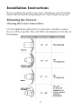
Rear Parking Sensor System
Model: PSS100
Installation Manual
TABLE OF CONTENTS
Warnings.......................................................................................2
Product Description ......................................................................3
Packing List ..................................................................................3
Installation Instructions ................................................................4
Mounting the Sensors .......................................................4
Installing the Power Harness ...........................................7
Mounting the Speaker.......................................................8
Mounting the Control Module ..........................................9
Specifications..............................................................................10
Maintenance................................................................................10
Troubleshooting..........................................................................10
Warranty .....................................................................................11
Features
•
•
•
•
•
•
•
•
Two reversing sensors detect obstacles up to 5 feet
Upgradeable to a 4 Sensor system (requires part #: PSS200)
Includes 0°, 4°, 8° and 16° sensor sleeves to fit most bumpers
Activates only when vehicle is in reverse
Will not drain battery or void factory warranty
Includes tricolor LED/speaker display with 3 settings - high,
low, and off
Three detection zones give the following warnings:
1 = slow beep within 3-5 feet
2 = medium beep within 1.3-3 feet
3 = steady tone within 1.3 feet
Works with any vehicle
1
Warnings
This product is intended to assist in safe driving by signaling the driver of
obstacles behind the vehicle while the vehicle is in reverse. You, as the
driver, are solely responsible for the safe operation of your vehicle and the
safety of your passengers according to your local traffic regulations. Do
not use any features of this system to the extent it distracts you from safe
driving. Your first priority while driving should always be the safe
operation of your vehicle. Audiovox Electronics Corporation cannot accept
any responsibility whatsoever for accidents resulting from failure to
observe these precautions or safety instructions.
1. This product utilizes high voltage. Any unauthorized modifications
or damage to the product may result in electrical shock. Handle all
components with care. Inspect regularly for damage to
components and cabling.
2. You are responsible for ensuring that the installation of this
product does not void or affect the vehicle manufacturer’s
warranty. Audiovox Electronics Corporation or its subsidiaries are
not liable in full or in part for improper installation resulting in
loss or damage to your property, or for voiding all or part of the
vehicle manufacturer’s warranty.
3. Do not apply excessive force to any of the components contained
within this kit. Excessive force used before, during or after
installation that results in a damaged or non-functional part will
void all warranties.
4. Please follow the procedures in this installation manual. Improper
installation or modification of this product will void all warranties.
2
Product Description
This Rear Parking Sensor System is designed to assist the driver by
providing an alert when an object is behind the vehicle whenever the
vehicle is shifted into reverse. Never rely solely on this product to ensure
the area is clear of children and/or obstructions. This product is not
intended to replace existing safety procedures, but rather to add an
additional safety tool for your vehicle.
Packing List
The model PSS100 Rear Parking Sensor System consists of the following
items:
1. Control box with Velcro pad
2. Sensors, 2 each, with 19.68ft (6M) length of cable
3. 9.84ft (3M) power cable
4. Tricolor LED display/speaker with 9.84ft (3M) length of cable
5. 2 each of the following sensor sleeves:
•
0°
•
4°
•
8°
•
16°
6. Hardware bag includes:
•
2 tap connectors
•
8 cable ties
•
1 Velcro pad (for module)
•
1 3M sticker (for speaker/LED display)
•
2 alcohol swab pads
•
Lock screw for LED display/speaker
•
Grounding screw/washer/ring terminal.
7. Installation Manual
8. User Manual
3
Installation Instructions
Before installing this product, take time to familiarize yourself with the
items in the box and use the packing list to verify all parts are present.
Mounting the Sensors
Choosing the Correct Sensor Sleeve
Use the application guide below to determine whether a sensor
sleeve will be required. This will affect the diameter of the hole in
the bumper.
4
Marking and Drilling Holes
Figure 1 (2 sensors)
Figure 2 (4 Sensors)
Mark the locations of the sensors on the rear bumper using a grease
pencil.
a) Identify the sensors’ height on the bumper and mark. The sensor
height should be between 18” and 30” from the ground.
b) Divide the bumper as shown in Figure 1 for a two sensor install or
as shown in Figure 2 for a four sensor install.
c) Install the sensors equally from the center of the bumper, as
shown in Figure 1 and Figure 2.
d) Inspect behind the bumper where the sensors are to be located to
check for possible obstructions, including metal braces, electrical
wires, and clearance. The sensors need 1.3” of clearance behind
the bumper to be fully inserted and mounted securely. Do not
mount sensors directly above exhaust pipes. Relocate the sensors
if any obstruction exists.
2. Before drilling the holes, use a center punch to make a dimple on the
bumper to prevent the drill from slipping from the intended mark.
3. Drill the sensor holes.
o Use a 26mm Hole Saw if you are using a sensor sleeve
o Use a 13/16” Hole Saw if you are installing without a sensor sleeve.
NOTE: Drill bits available for purchase from Audiovox.
o When drilling a metal bumper, remove the sharp edges using a round
metal file. Be careful not to enlarge hole when filing.
1.
5
Installing the Sensor Sleeve and Sensors
NOTE: When installing the sensors into the sensor sleeves, push on the outer
ring of the sensor only. Never push on the center of the sensor.
1. Ensure sensors and sleeves are upright (All products have an alignment mark
on the top).
2. If required, install the sensor into the sleeve.
3. Install the sensor (with sleeve if required) into the holes
drilled in the bumper.
Alignment Mark
4. Run the sensor wires through the sensor sleeves in the
bumper.
5. Press on the outer ring of the sensor and push until the
sensor is flush with the bumper. The sensor should fit snugly into the bumper
and lock into place.
6. Determine where the sensor wires will enter into the trunk area or passenger
compartment. Many vehicles have a factory grommet to allow routing of
wires from the outside to the inside of the vehicle. If needed, drill a hole to
route the wires into the vehicle, taking care when drilling metal. Smooth
edges with a round metal file and use a rubber grommet to protect the wires.
7. Feed the sensor wires through the factory grommet or other opening into the
vehicle for connection to the control module (e.g., into the cab of most trucks
or the trunk of passenger cars).
NOTE: Once the wires are passed through, make sure there is enough wire to
route to the control module. Check that the sensor wires will not be
pinched by moving parts or panels.
8. Cable tie the sensor wires and the power harness wires behind the bumper,
keeping them away from the exhaust system or moving suspension parts
(install power harness before using cable ties). Do not pull on the sensor
wires near the sensor shaft exit point, as this may damage the inner
connections.
6
Installing the Power Harness
Tap/Run Connection
1.
2.
Wire the Power Harness to the vehicle’s reverse lamp.
a) Locate the reverse lamp in the tail light assembly. Using the tap
connector supplied, perform the following steps:
i.
Place the un-stripped positive lead wire on the run channel.
ii. Insert the un-stripped red power wire completely.
iii. Make the connection between the wires by crimping down the
metal connector with a pair of pliers, making sure the metal is
flush with the plastic insulator.
iv. Close the top hinged cover until latched.
b) Attach the black wire to the vehicle body or to a ground wire
directly attached to the vehicle body. If attaching to another wire:
i.
Place the un-stripped ground lead wire on the
run channel.
ii. Insert the un-stripped black ground wire completely.
iii. Make the connection between the wires by crimping down
the metal connector with a pair of pliers, making sure the
metal is flush with the plastic insulator.
iv. Close the top hinged cover until latched.
Route the power harness wires with the sensor wires to the control box.
7
Mounting the Speaker
The speaker has three volume settings: Off, Hi, and Low. Since the speaker
can be adjusted as needed, you should mount the speaker in an accessible
location in the interior. Speaker should be visible by driver, allowing them to
see the LED indicators.
1. Route the wires for the speaker to the area where you will install the
control module. Make sure they will not be pinched by the panel or
moving parts.
2. Clean the back of the speaker and the mounting location to ensure
good adhesion. When the location is dry, peel the backing strip off the
Velcro tape and place on the back of the speaker. Next, peel the
backing strip off the other side of the Velcro tape and press on the
cleaned surface. Use the optional mounting screws (provided), if
necessary.
8
Mounting the Control Module
Determine a dry place inside the vehicle (out of the way) to mount the control
module (e.g., behind an inner body panel), making sure that all wiring will
reach the intended location.
1. Plug the sensor wires, speaker and power harness into the control
module before mounting. The sensor must be plugged into the
corresponding socket (see Figure 4). The control module is pre-fitted
with Velcro for mounting.
2. Clean the pre-selected mounting area to ensure good adhesion.
3. When the surface is dry, peel the backing off the Velcro pad and
attach the control module.
LS – Left Side Sensor (only used in 4 sensor install)
RS – Right Side Sensor (only used on a 4 sensor install)
Figure 4
9
Specifications
Power Supply
Current Draw
Detecting Distance
Sensor Cable Length
Operating Temperature Range
DC9V-DC16V
<120mA
0ft – 5ft
19.68ft (6M)
-0°F ~ 176°F
Maintenance
Though your backup system requires minimum care, you should maintain its
condition and performance using the following the guidelines:
• Keep the control box away from moisture, extreme heat or cold.
• Keep the sensors free from snow, ice, and debris.
Diagnostics / Trouble Shooting
Problem
No sound when reverse gear is
engaged.
1 Beep
2 Beeps
3 Beeps
4 Beeps
System beeping without
obstacle behind vehicle
Solution
1. Check if ignition/reverse light on
2. Check power cable connection
3. Check switch on speaker
System is functioning correctly
1 sensor is disconnected/damaged
2-3 Sensors are disconnected/damaged
No sensors are connected
1. Ensure sensor is mounted upright.
2. Remove anything mounted on the
vehicle that may be in the detection
area.
3. Ensure correct hole size has been
drilled in bumper.
4. Verify sensor is installed at the correct
height.
5. Verify sensor is in the correct position.
6. Check all connections.
7. Ensure module is not mounted near
electrical components with high
current.
8. Verify supporter was used if required
(angled/metal bumpers).
10
11
© 2009 Audiovox Electronics Corp., 150 Marcus Blvd., Hauppage, NY
12