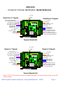
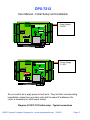
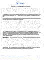
1
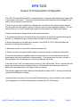
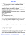
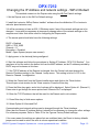
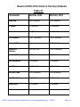
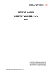
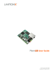
DPX-7212
Cypress Duprex Wireless LAN version
User Manual
MAN-SY-DPX-7212-v102
©2005 Cypress Computer Systems,Inc. • www.cypressworld.com 3/30/05
Page 1
DPX-7212
Connector Terminal Identification- Quick Reference
+8 - 24 VDC
Gnd
Panel /Port # 1 Signals
Panel/Port # 2 Signals
Alarm Programming Resistor
Aux. #3 Programming Resistor
Aux. Digital I/O #1 Input
Aux. Digital I/O #2 Output
Aux. Digital I/O #3 Output
Alarm Relay N.O..
Alarm Relay Com
Alarm Relay N.C.
LED
Data 1 /Data
F-2F/ Data 0 / Clock
+5 VDC
Ground
+8 - 24 VDC
+8 - 24 VDC
Ground
+5 VDC
F-2F/ Data 0 / Clock
Data 1 /Data
LED
C
Alarm Relay N.C
Alarm Relay Com
Alarm Relay N.O.
Aux. Digital I/O #3 Output
Aux. Digital I/O #2 Output
Aux. Digital I/O #1 Input
Aux. #3 Programming Resistor
Alarm Programming Resistor
Duprex Central Unit
+8 - 24 VDC
Reader # 1 Signals
Gnd
Reader # 2 Signals
Alarm Digital Input
Aux. Digital I/O #3 Input
Aux. Digital I/O #1 Output
Aux. Digital I/O #2 Input
N/C
Strike Relay N.O.
Strike Relay Com
Strike Relay N.C.
LED
Data 1 / Data
F-2F/ Data 0 / Clock
+5 VDC
Ground
+8 - 24 VDC
+8 - 24 VDC
Ground
+5 VDC
F-2F/ Data 0 / Clock
Data 1 / Data
LED
R
R
Strike Relay N.C.
Strike Relay Com
Strike Relay N.O..
N/C
Aux. Digital I/O #2 Input
Aux. Digital I/O #1 Output
Aux. Digital I/O #3 Input
Alarm Digital Input
Duprex Remote Unit
Refer to DPX-7000 Operators manual for detailed description of connections and reader format DIP
Switch settings.
©2005 Cypress Computer Systems,Inc. • www.cypressworld.com 3/30/05
Page 2
DPX-7212
DIP Switch Settings- Quick Reference
To gain access to the DIP Switch, Un-plug the WiFi Module by removing this screw.
“Factory Defaults” Strap
CENTRAL UNIT ONLY
Dip switch #5 is ON: Alternate IO Assignment
a. Door Strike relay does NOT follow LED
(Auxiliary setting, will follow Digital Input #1)
b. Alarm Relay and Digital Output #3 swap functions.
Restoring Factory Defaults
(Only takes effect during power up)
On
Restore Duprex Defaults
Restore WiPort Defaults
Service Mode 1
Service Mode 2
Normal Operation
Switch
1
2
on off
on on
on off
on on
off ..
1 2 3 4 5 6 7 8
Off
Strap
In
In
Out
Out
Out
NOT USED
ALL OFF
Switch
6 7 8
.. = Don’t care
Wiegand 0
Wiegand / No Filter 1
Strobed Rising Edge (MR-5) 2
Strobed Rising Edge (Dorado 644) 3
Strobed Rising (Mag-Tek)
Strobed Falling Edge
Reserved
Unsupervised F/2F
4
5
6
7
x
x
x x
x = ON
x
x
x
x x
x x x
All settings except Switch 5 are the
same for Central and Remote units.
©2005 Cypress Computer Systems,Inc. • www.cypressworld.com 3/30/05
Page 3
FCC Part 15 Notice of Compliance
This device operates under Part 15 of the FCC rules. There are several requirements that
must be met to maintain compliance.
These devices can only be used with approved antennas.
The antennas for these units MUST be mounted at a distance of 20 cm or greater from any
nearby persons.
This equipment has been tested and found to comply with the limits for a Class A digital device,
pursuant to part 15 of the FCC Rules. These limits are designed to provide reasonable
protection against harmful interference in a commercial installation. This equipment
generates, uses, and can radiate radio frequency energy and, if not installed and used in
accordance with the instructions, may cause harmful interference to radio communications.
However, there is no guarantee that interference will not occur in a particular installation. If this
equipment does cause harmful interference to radio or television reception, which can be
determined by turning the equipment off and on, the user is encouraged to try to correct the
interference by one or more of the following measures:
- Reorient or relocate the receiving antenna
- Increase the separation between the equipment and receiver.
- Connect the equipment into an outlet on a circuit different from that to which the receiver is
connected.
- Consult the dealer or an experienced radio/TV technician for help.
FCC Part 15 COMPLIANCE
This device complies with part 15 of the FCC Rules.
Operation is subject to the following two conditions:
(1) This device may not cause harmful interference, and
(2) this device must accept any interference received,
including interference that may cause undesired operation.
©2005 Cypress Computer Systems,Inc. • www.cypressworld.com 3/30/05
Page 4
DPX-7212
User Manual - Initial Setup and Installation
The DPX-7212 operates in the same manner as the DPX-7000 wired version. This
document covers the network portions of operation. Refer to the DPX-7000 user manual for
details on the I/O and data format operations. The DPX-7212 operates in the same manner
as all other members of the Duprex series, except that the data link is provided by an
Wireless TCP/IP connection.
It is suggested that a bench top verification as described below be performed. This will
provide a known reference point of proper operation, and will greatly aid in troubleshooting
in the event of problems.
Bench top verification of operation.
1. Connect units as shown in Diagram #1. A source of power will be needed for both
units. A single supply can be used to power both units, or a separate supply can be used
for each unit.
2. DIP Switch #1 on both units should be in the “ON” position. This setting places the
units in setup/diagnostic mode.
3. Apply power to both units. After a short delay, both units should begin communicating.
This will be indicated by the Amber communication LED flashing rapidly on both units ,
and the Diagnostic LED flashing Green slowly.
4. Move DIP Switch #1 to “OFF” on both units. The Amber communication LED should
stop flashing. The units are now in Normal “Quiet” mode. This preserves network
bandwidth. Periodically the units will establish contact with each other to verify the data
link. Communication will also occur when a change in I/O status occurs such as a contact
changes state, or a badge is read.
5. Verify Quiet Mode operation. Place a jumper between one of the LED inputs on the
Central unit and Ground. You should see the Amber communication LED on both units
flash to indicate a change of state.
If everything operates up to this point, the units are ready to be installed.
NOTE: The units are shipped from the factory with a default TCP/IP Address for each unit.
As shipped, they will communicate with each other without changing any settings. If more
than one pair are operating within range of each other at the default settings (same
address) then the units will interfere with each other and unpredictable operation can
result. When performing initial testing on multiple pairs, only test one pair at a time to
eliminate the possibility of interference. If only one pair are in use, the factory default
settings can be left in place.
©2005 Cypress Computer Systems,Inc. • www.cypressworld.com 3/30/05
Page 5
DPX-7212
User Manual - Initial Setup and Installation
Power Supply
12 VDC
R
Power Supply
12 VDC
R
All you need to do is apply power to both units. They will start communicating
immediately unless there are other units with the same IP addresses. No
router is necessary for initial bench testing.
Diagram #1 DPX-7212 Initial setup - Typical connections
©2005 Cypress Computer Systems,Inc. • www.cypressworld.com 3/30/05
Page 6
DPX-7212
User Manual - Initial Setup and Installation
Each Duprex DPX-7212 pair is configured with a default TCP/IP address.
Duprex Central = 192.168.1.58
Duprex Remote = 192.168.1.59
It may be necessary to change these settings to be compatible with the network that will be
used in the final installation. The DPX-7212 system requires the use of fixed IP addresses to be
assigned to the units. It may be necessary to coordinate with the System Administrator before
placing the devices on a network.
The Lantronix WiPort Device Installer program can be used. Each order for the DPX-7212 will
include a CD containing the program. If for some reason the program has not made it to you, it can
be downloaded from www.lantronix.com under support/downloads/WiPort Device Installer.
This manual will describe how to change the IP address for the units using the WiPort
Device Installer software. Once the Addresses have been set to be compatible with the network,
final installation can be made. It will be necessary to have a wireless 802.11 router to change the
TCP/IP settings.
It is beyond the scope of this manual to describe switch/router and other complex network settings
and topologies. It will be incumbent upon the end user or system administrator to determine how to
configure their network equipment to allow operation of the DPX-7212 units.
During the configuration process some settings may be changed inadvertently that will cause the
units to cease operation. A strap is provided on the WiPort Module to reset to Standard Duprex
Defaults or Factory Defaults.
The different modes of operation are described below:
Duprex Defaults set the unit to the “shipped from factory” setting. This allows the Central and Remote to communicate directly
with each other without a router by setting static IP addresses.
WiPort Defaults set the unit to DHCP mode in order to initiate configuration using the Installer Driver Software.
Service Mode 1 (Central Unit) does not change the WLAN settings but forces continuous polling for installation and
troubleshooting.
Service Mode 2 is reserved for future use.
Normal Operation Mode is the recommended operational configuration. Network traffic is reduced to event driven communication
and periodic supervision.
©2005 Cypress Computer Systems,Inc. • www.cypressworld.com 3/30/05
Page 7
DPX-7212
Duprex 7212 Operational Modes
Duprex Defaults: Set DIP switch #1 ON, switches 2-8 OFF. Install the Factory Default strap
onto the Duprex radio board (See DIP Switch settings - quick reference). Cycle power to the unit.
The unit will reset itself to the Cypress factory default settings. The Diagnostic LED will flash
Green about 30 times and will illuminate a steady green when the process is finished.
If the diagnostic LED turns Red, a problem has occurred with the reprogramming process. If this
happens recycle power to the unit. A steady Green LED will indicate a successful reset of the
unit.
After completing this procedure for both the Central and Remote units, they should communicate
with each other using the fixed default IP addresses.
WiPort Defaults: Set DIP switch #1 and #2 ON, switches 3-8 OFF. Install the Factory Default
strap onto the Duprex radio board (See DIP Switch settings - quick reference). Cycle power to
the unit. The unit will reset itself to the WiPort factory default settings. The Diagnostic LED will
flash Green about 30 times and will illuminate a steady green when the process is finished.
If the diagnostic LED turns Red, a problem has occurred with the reprogramming process. If this
happens recycle power to the unit. A steady Green LED will indicate a successful reset of the
unit.
This mode sets the units to look for a DHCP host on the 802.11 network and is used only to
establish initial communication with the Device Installer software for configuration purposes. The
units will not communicate with each other using DHCP and must be provided with fixed IP
addresses. The final configuration will have to be completed manually through the Lantronix
Device Installer program.
Service Mode 1: Set DIP Switch #1 ON, 2-8 OFF. Remove the Factory Default strap from the
Duprex radio board. Cycle power to both units. The units will reset and should begin
communicating with each other. The amber comm LED should flash rapidly as communication
takes place. The Green diagnostic LED should flash slowly on both the Central and Remote
units. This mode is useful for diagnostic purposes, and to determine if the units are within range.
Normal Operation Mode: SET DIP Switch #1 OFF, 2- 8 are set according to the data format and
other required options. Cycle power to both units. The units will reset and will briefly
communicate. The Green diagnostic LED should flash slowly on both the Central and Remote
units. This mode is used to conserve bandwidth, communication is minimized.
©2005 Cypress Computer Systems,Inc. • www.cypressworld.com 3/30/05
Page 8
DPX-7212
Duprex 7212 Description of Operation
The DPX-7212 uses Wireless 802.11 communications to relay door/gate signals and reader data
to an access control panel. There are several parameters that may need to be changed in the
field to use the units at a particular site.
If only one pair of units is utilized at a particular site, and there is no existing wireless network,
then the units will work together right out of the box with no further changes necessary. The two
units will form an “Ad Hoc” network and establish a link between the Central and Remote.
It may be necessary to change some of the network settings if:
a. An existing network is on the site and the user would like to access the modules through the
network. i.e. change settings or mointor status through the wireless network.
b. Secure encryption of the data link is required. See AN-DPX-7212-1 which describes the
process for securing the wireless link.
c. More than one pair of units will be used at the same site.
d. There is a need to change network names or channel numbers to eliminate interference.
If a wireless acess point is available when the units power up, the units will connect the the
access point and use its facilities for communication. If the access point lost due to power or
other problems, the link between the Central and Remote will be lost.
If the units do not “see” an access point at power up, they will form the “Ad Hoc” network and will
ignore any access points not seen at power up. In other words, the access point has to be
powered up and ready before the Duprex units are running.
The following pages detail basic setup and configuration using an 802.11 access point and the
Lantronix® configuration software.
Advanced users can refer to the Lantronix® documentation for further details on the operation
and configuration of the Wi-Port® modules used with the DPX-7212 system.
©2005 Cypress Computer Systems,Inc. • www.cypressworld.com 3/30/05
Page 9
Standard setup for 802.11 configuration of DPX-7212
Ethernet connection to
Wireless Access Point
Host computer with Lantronix
configuration software loaded
802.11 Wireless Access Point
12 Volt
Power
Supply
C
DPX-7212(s) to be configured
©2005 Cypress Computer Systems,Inc. • www.cypressworld.com 3/30/05
Page 10
DPX-7212
Changing the IP Address and network settings - Cypress Default
This method connects to the Duprex units using the Cypress Default settings.
1. Install the Lantronix “WiPort Device Installer” software from the distribution CD or Lantronix
web site (www.lantronix.com).
2. It will be necessary to have an 802.11 Wireless router if any of the network settings are to be
changed. It may also be necessary to temporarily change some of the network settings on the
computer and router that will be used for configuring the Duprex units.
3. Set the Computer TCP/IP address to the same subnet (192.168.1.xxx) as the Duprex units.
Any address except 58 and 59 will work.
4. Set the Wireless Router (access point) to the same subnet (192.168.1.xxx) . The access point
should also have the following settings:
SSID = LTRX_IBSS
Channel = 11
Encryption = Disabled
Mode = Open System (anyone can connect)
5. Apply power to the device(s) being configured.
6. Start the software and follow the procedures in the “Setting IP Address - DPX-7212 Section”
7. If the TCP/IP address of the Remote is changed, then the Central unit must change the
Remote IP address setting in the Channel 1 setup menu. This setting is left at 0.0.0.0 in the
Remot e Channel 1 configuration.
8. Select the Central unit from the Device Installer menu and click on the Telnet button.
This will open a text window for the Telnet session. Press the Enter key.
9. Press the Enter key again, and a list of options will be displayed. Select Option #1 (Channel 1)
Press enter to go through the menu options until “Remote Port” is displayed.
10. Enter the TCP/IP address that will be used for the Remote unit in dot notation.
11. Press Enter key to finish menu options.
12. Select Option #9 “Save and Exit”
Communication and network settings can be changed through the Telnet interface.
Other than the Remote IP address setting it should not be necessary to change the other settings.
For reference purposes, Refer to Table #1 for the Cypress Factory Default settings.
If for some reason the settings are placed into an undefined state, the Reset to factory defaults
jumper can be used to return the units to a know operational condition.
©2005 Cypress Computer Systems,Inc. • www.cypressworld.com 3/30/05
Page 11
DPX-7212
Changing the IP Address and network settings - WiPort Default
This method connects to the Duprex units using the Wi-Port Default settings.
1. Set the Duprex units to the Wi-Port Default settings.
2. Install the Lantronix “WiPort Device Installer” software from the distribution CD or Lantronix
web site (www.lantronix.com).
3.It will be necessary to have an 802.11 Wireless router if any of the network settings are to be
changed. It may also be necessary to temporarily change some of the network settings on the
computer and router that will be used for configuring the Duprex units.
4. The access point should also have the following settings:
DHCP = Enabled
SSID = LTRX_IBSS
Channel = 11
Encryption = Disabled
Mode = Open System (anyone can connect)
5. Apply power to the device(s) being configured.
6. Start the software and follow the procedures in “Setting IP Address - DPX-7212 Section”. You
may have to find the units in the device list from the MAC address, as the IP address provided by
DHCP may not be known at this time.
7. If the TCP/IP address of the Remote is changed, then the Central unit must change the
Remote IP address setting in the Channel 1 setup menu. This setting is left at 0.0.0.0 in the
Remot e Channel 1 configuration.
8. Select the Central unit from the Device Installer menu and click on the Telnet button.
This will open a text window for the Telnet session. Press the Enter key.
9. Press the Enter key again, and a list of options will be displayed. Select Option #1 (Channel 1)
Press enter to go through the menu options until “Remote Port” is displayed.
10. Enter the TCP/IP address that will be used for the Remote unit in dot notation.
11. Press Enter key to finish menu options.
12. Select Option #9 “Save and Exit”
Communication and network settings can be changed through the Telnet interface.
Other than the Remote IP address setting it should not be necessary to change the other settings.
For reference purposes, Refer to Table #1 for the Cypress Factory Default settings.
If for some reason the settings are placed into an undefined state, the Reset to factory defaults
jumper can be used to return the units to a know operational condition.
©2005 Cypress Computer Systems,Inc. • www.cypressworld.com 3/30/05
Page 12
Reset of DPX-7212 Units to Factory Defaults
Table #1
Parameter
Central Unit
Remote Unit
Baud rate
9600 (Default)
9600 (Default)
I/F Mode
4C (Default)
4C (Default)
Flow
00 (Default)
00 (Default)
Port Number
10001 (Default)
10001 (Default)
Connect Mode
C1
C0 (Default)
Remote IP
Address
192.168.1.59
0.0.0.0 (Default)
Remote Port
10001
00 (Default)
DisConnMode
00 (Default)
00 (Default)
FlushMode
00 (Default)
00 (Default)
DisConnTime
00:00 (Default)
00:00 (Default)
SendChar 1
00 (Default)
00 (Default)
SendChar 2
00 (Default)
00 (Default)
©2005 Cypress Computer Systems,Inc. • www.cypressworld.com 3/30/05
Page 13
Setting IP Address - DPX-7212
Search
Button
Device in
List
1. Start the Lantronix WiPort Installer software. Click the “Search” button, after a
brief delay, the connected device(s) should appear in the device list as shown above.
Note: If the unit(s) do not appear in the device list, check power and network
settings. You will not be able to proceed if you are unable to see the unit(s) to be
configured in the device list.
2. Select the device to be configured with a mouse click. The device will highlight in
blue as shown above when selected. Verify which device is to be configured by the
MAC address. The MAC address is printed on the WiPort module. i.e. make sure
you are configuring the correct Central unit or Remote unit.
©2005 Cypress Computer Systems,Inc. • www.cypressworld.com 3/30/05
Page 14
Setting IP Address - DPX-7212
3. Click on Assign IP. The dialog box above will open. Select “Assign a specific
IP address and click “Next”.
4. Enter the IP address for the unit in dot notation. The Netmask can also be entered
at this time.
©2005 Cypress Computer Systems,Inc. • www.cypressworld.com 3/30/05
Page 15
Setting IP Address - DPX-7212
5. Click on “Assign”.
6. Click on “Finish”. The new TCP/IP address should now be assigned to the unit.
©2005 Cypress Computer Systems,Inc. • www.cypressworld.com 3/30/05
Page 16