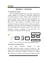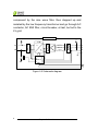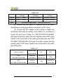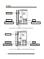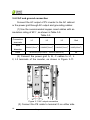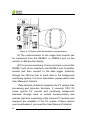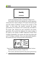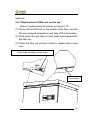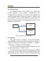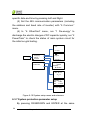
1
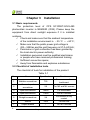
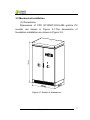
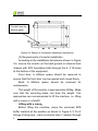
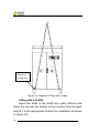
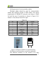
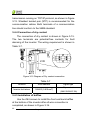
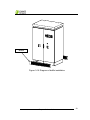
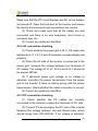
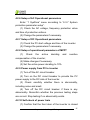
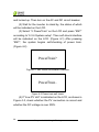
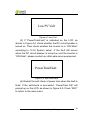
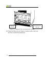
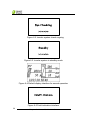
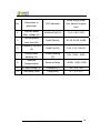
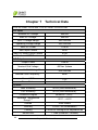
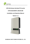
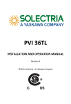
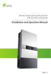
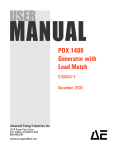
CPS SC Series
Photovoltaic Grid Connection Inverter
CPS SC100KT-O/US-480
Installation and Operation Manual
Shanghai CHINT Power Systems Co., Ltd.
Table of Contents
Chapter 1
IMPORTANT SAFETY INSTRUCTIONS......1
Chapter 2 Overview .....................................................3
2.1 Grid-tie PV system .............................................3
2.2 Inverter circuit structure......................................3
2.3 Appearance ........................................................5
Chapter 3 Installation...................................................6
3.1 Basic requirements.............................................6
3.2 Checklist of installation tools ..............................6
3.3 Mechanical installation .......................................7
3.4 Electrical installation ...........................................11
3.4.1 DC connection.............................................14
3.4.2 AC and ground connection ..........................18
3.4.3 Communication connection .........................19
3.4.4 Connection of dry contact............................22
3.4.5 Installation of baffles....................................22
Chapter 4 Initial On-grid Testing.................................24
4.1 Testing steps ......................................................24
4.2 Testing procedure statement ..............................24
4.2.1 Appearance of inverter checking .................24
4.2.2 AC connection checking ..............................25
4.2.3 DC connection checking..............................25
4.2.4 Power supply from grid to inverter...............26
4.2.5 System self-check and time set-up..............26
4.2.6 Setup of AC Operational parameters...........27
1
4.2.7 Setup of DC Operational parameters ..........27
4.2.8 Setup of operational parameters of MPPT ..27
4.2.9 Power supply from PV to inverter................27
4.2.10 Self-check of power train...........................27
4.2.11 Inverter start-up .........................................30
Chapter 5 Operation ....................................................31
5.1 Start-up and shut-down ......................................31
5.1.1 Start-up .......................................................31
5.1.2 Shutdown ....................................................31
5.2 Operation mode .................................................35
5.3 Troubleshooting..................................................37
5.4 Filter net cleaning and replacement ...................42
5.4.1 Replacement of filter net on the top ............43
5.4.2 Replacement of internal filter net.................44
Chapter 6 Human Machine Interface..........................47
6.1 Description of LCD display .................................47
6.2 Operation state...................................................48
6.3 Interface and menu functions .............................49
6.3.1 Interface types.............................................49
6.3.2 Main operation interface..............................51
6.3.3 Operation information..................................52
6.3.4 Present fault ................................................53
6.3.5 History.........................................................53
6.3.6 System setup ..............................................55
6.3.7 System protection parameter setup ............56
Chapter 7
2
Technical Data ............................................60
Chapter 8 Quality Assurance ......................................62
8.1 Warranty.............................................................62
8.2 Disclaimer...........................................................62
8.3 Quality clause (Warranty clause)........................62
3
Chapter 1 IMPORTANT SAFETY INSTRUCTIONS
(SAVE THESE INSTRUCTIONS)
Please read this manual carefully before installation. The
warranty will be invalid automatically if the user does not
follow this manual during installation and operation resulting
in damage to the equipment.
ELECTRIC SHOCK HAZARD:
All operations and wiring should be performed by qualified
technical personnel.
Disconnect the inverter from PV assemblies and the Grid
before the maintenance and operation of the equipment.
At the same time, make sure that equipment is grounded
properly. If a ground fault is indicated, the grounding
conductors are probably ungrounded and energized.
WARNING:
1. When the connected PV module is exposed to the
sunlight, it generates DC voltage and charges the DC bus
capacitors of the inverter. Electric charges are still stored in
the capacitors even the input of the PV inverter is turned off.
Therefore, equipment shall not be maintained or operated
1
Chapter 1
IMPORTANT SAFETY INSTRUCTIONS
until 15 minutes after all inputs are cut off or the “discharge”
command is carried out successfully through LCD button
operations.
2. This inverter is specially designed to connect AC
power to the public grid. Do not connect the AC output of this
equipment directly to private AC power equipments.
3. Please choose the type of inverter based on the way of
DC grounding system! Change of PV grounding in the
inverter is prohibited without permission. Please contact our
after-sale service personnel if the change of grounding in the
inverter is necessary.
4. To ensure operational safety, run the initial on-grid testing
before operating the CPS SC100KT-O/US-480.
HIGH TEMPERATURE:
Do not touch the metal surfaces of the radiator and inverter
during the operation of the inverter.
2
Chapter 1
IMPORTANT SAFETY INSTRUCTIONS
Chapter 2
Overview
2.1 Grid-tie PV system
CPS SC100KT-O/US-480 grid connection photovoltaic
inverter applies to all kinds of commercial rooftop grid
connected system or power station system. Normally, the
system consists of PV modules, DC power distribution unit,
grid connection inverter and AC power distribution unit
(Figure 2-1). Solar energy is converted to direct current
through PV modules. The direct current is then converted to
alternative current with the same frequency and phase as
the grid through grid connection inverter. All or part of the
alternative current is supplied to the local load. The
remaining or all electricity is fed to the grid.
AC grid
AC power
distribution
unit
DC power
distribution
unit
Metering
out
Metering
in
AC load
Figure 2-1 Grid connection photovoltaic power generation system
2.2 Inverter circuit structure
The
basic
schematic
diagram
of
CPS
SC100KT-O/US-480 inverter is shown in Figure 2-2. The
output of PV modules first passes through DC circuit breaker.
The inverter converts DC voltage to 3-phase AC voltage.
The 3-phase AC voltage will be removed of high frequency
3
Chapter 2
Overview
component by the sine wave filter, then stepped up and
isolated by the low frequency transformer and go through AC
contactor, AC EMI filter, circuit breaker, at last, be fed to the
LV grid.
Figure 2-2 Schematic diagram
4
Chapter 2
Overview
2.3 Appearance
Figure 2-3 Appearance sketch
Description of main components (shown in Figure
2-3):
1、Roof Panel
2、Operation buttons and LCD display panel
3、Emergency stop button
4、Door lock
5、AC circuit breaker
6、DC circuit breaker
5
Chapter 2
Overview
Chapter 3
Installation
3.1 Basic requirements
The protection level of CPS SC100KT-O/US-480
photovoltaic inverter is NEMA3R (IP44). Please keep the
equipment from direct sunlight exposure if it is installed
outdoors.
9 Check and make sure that the ambient temperature
of the installation environment is -25 °C ~+60°C;
9 Make sure that the public power grid voltage is
422~528Vac and the grid frequency is 57.0~60.5Hz;
9 Permission of grid connection has been granted by
the local electric power authority;
9 Installation personnel must be qualified electricians
or people who have received professional training;
9 Sufficient convection space;
9 Away from flammable and explosive substances
3.2 Checklist of installation tools
The checklist of tools for installation of the product:
Table 3-1
No.
Name
Specification
Function
1
Wabbler screwdriver
T25
For screws on the
backboard
2
Cross-shaped
screwdriver
2#
For M3 and M4 screws
3
Open end wrench
14mm
For M8 screws
4
Open end wrench
17mm
For M10 screws
5
Straight screwdriver
2#
For screws on dry
contact
6
Sleeve
7mm
For M4 nuts
7
Torque wrench
/
For M10 screws
6
Chapter 3
Installation
3.3 Mechanical installation
(1) Dimensions
Dimensions of CPS SC100KT-O/US-480 grid-tie PV
inverter are shown in Figure 3-1.The dimensions of
foundation installation are shown in Figure 3-2:
m
m
0
5
8
1
Figure 3-1 Sketch of dimensions
7
Chapter 3
Installation
Conduit area on
bottom panel
Figure 3-2 Sketch of foundation installation dimensions
(2) Requirements of inverter installation:
According to the installation dimensions shown in Figure
3-2, secure the inverter on the hard ground or channel steel
chassis with M12 foundation bolts through the 8 ¢16 holes
at the bottom of the equipment.
Front door: A 650mm space should be reserved to
ensure that the front door can be opened and closed freely.
Back: A 800mm space should be reserved for
maintenance.
The weight of the inverter is approximately 900kg. Make
sure that the mounting place can bear the weight. Two
approaches are recommended to lift the machine, i.e. lifting
with a crane or a forklift:
Lifting with a crane:
Before lifting the machine, place the enclosed EPE
buffer material at the position as shown in Figure 3-3. Put 2
strings of sling rope(each no shorter than 7 meters)through
8
Chapter 3
Installation
the machine from the left to the right foot bottom. Then lift the
machine slowly to the appropriate location for installation
with the crane (shown in Figure 3-4).
EPE
EPE
Figure 3-3 Diagram of EPE placement
9
Chapter 3
Installation
Placement
of sling rope
Figure 3-4 Diagram of lifting with a crane
Lifting with a forklift:
Adjust the width of the forklift arm within 850mm and
insert the fork into the bottom of the machine from the back
and lift it to the appropriate location for installation as shown
in Figure 3-5.
10
Chapter 3
Installation
<850
Figure 3-5 Diagram of lifting with a forklift
3.4 Electrical installation
Open the front door of the machine. Proceed as shown
in Figure 3-6.
1 、 Turn the handle bar of DC circuit breaker
anti-clockwise to horizontal position.
2 、 Turn the handle bar of AC circuit breaker
anti-clockwise to horizontal position.
3、Unlock the door with the key. Pull the door knob 45
degree outward to open the front door.
11
Chapter 3
Installation
1
3
2
Figure3-6 Diagram of opening front door
4、After opening the front door, remove the transparent
Plexiglas cover at the bottom of the machine and connect
the external cables to the inverter, as shown in Figure 3-7.
The incoming and outgoing cables are routed from the
bottom. It is recommended that all the cables are routed
along the cable trenches for the convenience of installation
and maintenance.
Cover I
Cover II
12
Chapter 3
Installation
A
B
Cover I
C
D
E
Cover II
Figure 3-7 Sketch of external wiring
Two ways of routing are available as follows:
(1) Routing from square conduit areas at the bottom:
Detach the screws from the bottom covers with a
cross-shaped screwdriver, remove the two covers and
connect cables through the square conduit areas.
(2) Routing from round holes on the bottom cover:
(a) Remove the cover screws, put the screws aside,
and then take off the two covers.
(b) Mark all the holes on cover I and II as shown in
Figure 3-7 for the conduits. Two conduits for DC
cables,one for the communication cables and one
13
Chapter 3
Installation
for the AC cables and grounding cable.
A,B:Conduit for DC cables
C: Conduit for communication cables
D: Conduit for AC cables
E: Conduit for the grounding cable
(c) Punch holes on the bottom cover for the conduits;
(d) Check the seal of the cover;
(e) Restore the cover to the equipment,attach the
screws;
(f) Insert the conduits into the openings;
(g) Attach the conduits with the appropriate hubs.
3.4.1 DC connection
(1) The following rules should be abided by to ensure
the highest efficiency of the PV inverter:
(a) First, make sure that the maximum open circuit
voltage of the PV modules is lower than 600Vdc
under any conditions;
(b) Ensure that the polarity of DC input is correct, i.e.
the positive pole of PV module is connected to the
positive pole of the inverter’s DC input, and the
negative pole of PV module is connected to the
negative pole of the inverter’s DC input;
(c) The Max. DC input current of the inverter is 350A,
so 35 ~ 95mm2 copper core cables with an
insulation rating of 90℃ are recommended for
inverter’s DC input, as shown in Table 3-2:
14
Chapter 3
Installation
Table 3-2
4 strings
3 strings
2 strings
Positive
2AWG(35mm²)
1/0AWG (50 mm²)
3/0AWG (95 mm²)
Negative
2AWG(35mm²)
1/0AWG (50 mm²)
3/0AWG (95 mm²)
Bolts
M10 bolts (torque value:10N-M or 88.5Lb-In.)
(2) Confirm that the input PV modules are of the same
specifications and types before connection of DC input;
(3) Connect the DC cables to the inverter’s copper bar
terminals of DC side according to the Table 3-3, as shown in
Figure 3-8 and 3-9. In Table 3-3, CPS SC100KT-O/US-480,
this type of inverter means that the negative pole of DC input
needs to be connected to the earth grounding wire and CPS
SC100KT-OPG/US-480, this type of inverter means that the
positive pole of DC input needs to be connected to the earth
grounding wire.
Table 3-3
Type of Inverter
Default way
PV -
of grounding
CPS
Negative
Connect to
SC100KT-O/US-480
grounding
ground bar
CPS
Positive
SC100KT-OPG/US-480
grounding
Hot
PV+
Hot
Connect to
ground bar
15
Chapter 3
Installation
GFDI board
Return
Hot
PV– of DC cables
PV+ of DC cables
Figure 3-8 DC connection of CPS SC100KT-O/US-480
GFDI board
Return
Hot
PV+ of DC cables
PV- of DC cables
Figure 3-9 DC connection of CPS SC100KT-OPG/US-480
16
Chapter 3
Installation
The schematic diagram of wire connection is shown in
Figure 3-10.
Outside the
inverter
Hot
Inside the
inverter
+ =
PV+
-
PVReturn
~
GFDI
Negative ground
Hot
+ =
PV-
-
PV+
Return
~
GFDI
Positive ground
Figure 3-10 Schematic diagram of DC side
The type of fuse is shown in Table 3-4. If a large stream
of electric current passes through, the fuse will be
disconnected and the GFDI circuit will detect the fault.
Solution of the problem may refer to “5.3 Troubleshooting”.
Table 3-4
Type of fuse
Bussmann KLM-2
Rated
Rated
Safety breaking current
current
voltage
on rated voltage
2A
600VAC
100kA@600VAC
Warning:
Please choose the type of inverter based on the way
of DC grounding system! Change of PV grounding in
the inverter is prohibited without permission. Please
contact our after-sale service personnel if the change of
grounding in the inverter is necessary.
17
Chapter 3
Installation
3.4.2 AC and ground connection
Connect the AC output of PV inverter to the AC cabinet
or the power grid through AC output and grounding cables:
(1) Use the recommended copper cored cables with an
insulation rating of 90℃, as shown in Table 3-5:
Table 3-5
Connection
terminals
Wire
L1
L2
L3
Gnd
2/0AWG(70mm2)
2/0AWG(70mm2)
2/0AWG(70mm2)
2AWG(35mm2)
diameter
Bolts
M10 bolts (torque value:10N-M or 88.5Lb-In.)
(2) Connect the power grid A, B, C cables to L1, L
2, L3 terminals of the inverter, as shown in Figure 3-11:
L1 L2 L3
Figure 3-11 AC output connection
(3) Connect the PE cable to terminal G on either side
18
Chapter 3
Installation
M8
of the ground bar.
Terminal G
Terminal G
Figure 3-12 Ground connection
(4) Make sure that all cables are tightened on L1, L2, L3
and G terminals properly.
3.4.3 Communication connection
(1)
RS485
communication
connection
(Standard
configuration):
The signal pinboard on the inverter has 3 RJ45
communication connectors, which are RS485-1, RS485-2
and Ethernet terminals, as shown in Figure 3-13. Customers
can connect the communication cables by themselves.
19
Chapter 3
Installation
RS485-1 RS485-2 Ethernet
Figure 3-13 Signal cable terminals for communication
(2) The communication of one single local inverter can
be connected from the RS485-1 or RS485-2 port on the
inverter to 485 bus bar directly.
(3) For remote monitoring of more inverters, connect the
RS485-1 port of one inverter to the RS485-2 port of another
inverter and then connect to the data logger (Interlink)
through the 485 bus bar to send data to the background
monitoring system. For more information, please refer to the
User Manual of Interlink.
1
Data collector (Interlink) integrates the PV system data
processing and detection functions. It connects CPS SC
series grid-tie PV inverter and monitoring background
Interview through local or remote communication and
realizes real-time monitoring of the various PV systems and
improves the reliability of the PV system. Please contact
your local dealers if you need the User Manual of Interlink.
20
Chapter 3
Installation
(4) Requirement of communication cables:
Shielded cables should be used for communication
cables with maximum length of 1000 meters. The wiring
requirements of RS485-1/2 connector are shown in Table
3-6 and the way of connection is shown in Figure 3-14.
Cables 1~8 are shown from left to right.
Table 3-6
No.
Color
Function
1
White orange
485+
2
Orange
N.C.
3
White green
485-
4
Blue
N.C.
5
White blue
N.C.
6
Green
N.C.
7
White brown
GND
8
Brown
N.C.
Figure 3-14 Diagram of RS485-1/2 crystal head wiring
(5) Ethernet communication connection (optional):
The Ethernet interface on the inverter is for data
21
Chapter 3
Installation
transmission running on TCP/IP protocol, as shown in Figure
3-13. Shielded twisted pair (STP) is recommended for the
communication cables. Both terminals of a communication
line should conform to the 568B standard.
3.4.4 Connection of dry contact
The connection of dry contact is shown in Figure 3-15.
The two terminals are potential-free contacts for fault
alarming of the inverter. The wiring requirement is shown in
Table 3-7.
Dry contact
干接点
Figure 3-15 Diagram of Dry contact connection
Table 3-7
Function
Wire diameter
Signal type
Inverter fault alarm
18AWG (0.810mm )
2
Dry contact
(MAX 240VAC 2A)
3.4.5 Installation of baffles
Use four M4 screws to install the front and back baffles
at the bottom of the inverter after all wire connection is
completed, as shown in Figure 3-16.
22
Chapter 3
Installation
Baffle
Figure 3-16 Diagram of baffle installation
23
Chapter 3
Installation
Chapter 4
Initial On-grid Testing
To ensure operational safety, initial on-grid testing is
required as per the instructions in this chapter before
connecting PV array and grid power after the installation of
CPS SC100KT-O/US-480.
4.1 Testing steps
Conduct the initial on-grid test of CPS
SC100KT-O/US-480 according to the following steps:
(1) Check the appearance of inverter
(2) Check the AC connection
(3) Check the DC connection
(4) Connect to the grid
(5) System self-check and time setup
(6) Set up the operational parameters of AC part
(7) Set up the operational parameters of DC part
(8) Set up the operational parameters of MPPT
(9) Connect to PV
(10) Self-check of power train
(11) Start up the inverter
Note: Please refer to “5.3 Troubleshooting” or contact
our after-sale service personnel if any problem is found
during the testing.
4.2 Testing procedure statement
4.2.1 Appearance of inverter checking
(1) Check whether the inverter has obvious abnormality.
24
Chapter 4
Initial On-grid Testing
Make sure that the DC circuit breaker and AC circuit breaker
are turned off. Open the front door of the inverter and ensure
the electrical components and connections are normal.
(2) Check and make sure that all the cables are well
connected and there is no wire looseness, short circuit or
insulation loss, etc.
(3) Correct any problems identified.
4.2.2 AC connection checking
(1) Check whether the power grid A, B, C, PE cables are
tightened on L1, L2, L3 and G terminals correspondingly and
properly.
(2) When the AC side of the inverter is connected to the
power grid, measure the voltage between two terminals of
AC cables. The voltage of L1-L2, L2-L3 and L3-L1 should all
be around 480Vac.
(3) If abnormal power grid voltage or no voltage is
detected, reconfirm the power transmission from the power
grid to the inverter. If there is nothing wrong with the power
transmission, check whether the cable connection is correct.
(4) Correct any problems identified.
4.2.3 DC connection checking
(1) Check whether the PV cables are correctly
connected to the inverter’s copper bar terminals of DC side.
(2) Connect PV and energize the DC side of the inverter.
Measure the voltage between Hot and Return bars, which
should range from 300~600Vdc. If no voltage is detected,
25
Chapter 4
Initial On-grid Testing
check whether the cable connection from DC source to the
inverter is correct.
(3) Confirm whether the polarity of DC connection is
correct.
(4) Correct any problems identified.
4.2.4 Power supply from grid to inverter
(1) Close the front door of the inverter.
(2) Turn on the AC circuit breaker. The auxiliary power
supply of the inverter is energized and the control circuit is
started up.
(3) Check carefully whether there is abnormality,
including noise or smell.
(4) Turn off the AC circuit breaker immediately if there is
any abnormality. Reconfirm whether the previous testing
steps are correct. Stop testing if no abnormality exists.
4.2.5 System self-check and time set-up
(1) “Sys. Checking” will be indicated on the LCD when
the AC circuit breaker is turned on.
(2) The inverter will stand by after the self-check of
system is completed. Meanwhile, fault indication interface
will be shown on the LCD if any malfunction occurs. The
specific fault indication and solution are available to be found
in “5.3 Troubleshooting”.
(3) Enter the “4 SysTime” menu and set up the present
date and time according to “6.3.6 System setup”.
26
Chapter 4
Initial On-grid Testing
4.2.6 Setup of AC Operational parameters
Enter “1 SysPara” menu according to “6.3.7 System
protection parameter setup”.
(1) Check the AC voltage, frequency protection value
and time of protection actions.
(2) Change the parameters if necessary.
4.2.7 Setup of DC Operational parameters
(1) Check the PV start voltage and time of the inverter.
(2) Change the parameters if necessary.
4.2.8 Setup of operational parameters of MPPT
(1)
Check
the
active
derating
and
reactive
compensation of the inverter;
(2) Make changes if necessary.
(3) Set the active power derating to 10%.
4.2.9 Power supply from PV to inverter
(1) Turn off the AC circuit breaker.
(2) Turn on the DC circuit breaker to provide the PV
power supply to the DC side of the inverter.
(3) Check carefully whether there is abnormality,
including noise and smell.
(4) Turn off the DC circuit breaker if there is any
abnormality. Reconfirm whether the previous testing steps
are correct. Stop testing if no abnormality exists.
4.2.10 Self-check of power train
(1) Confirm that the front door of the inverter is closed
27
Chapter 4
Initial On-grid Testing
and locked up. Then turn on the AC and DC circuit breaker.
(2) Wait for the inverter to stand by, the status of which
will be indicated on the LCD.
(3) Select “2 PowerTrain” on the LCD and press “ENT”
according to “6.3.6 System setup”. Then self-check interface
will be indicated on the LCD. (Figure 4-1) After pressing
“ENT”, the system begins self-checking of power train.
(Figure 4-2)
PowerTrain?
Figure 4-1 Self check confirmation interface
PowerTrain..
Figure 4-2 Power train self check
(4) If “Low PV Volt” is indicated on the LCD, as shown in
Figure 4-3, check whether the PV connection is correct and
whether the DC voltage is over 300V.
28
Chapter 4
Initial On-grid Testing
Low PV Volt
Figure 4-3 Low Volt
(5) If “PowerTrainFualt” is indicated on the LCD, as
shown in Figure 4-4, check whether the DC circuit breaker is
turned on. Then check whether the inverter is in “ON State”
according to “6.3.6 System setup”. If the fault still occurs
when the DC circuit breaker is turned on and the inverter is
“ON State”, please contact our after-sale service personnel.
PowerTrainFault
Figure 4-4 Self check fails
(6) Restart the self-check of power train when the fault is
fixed. If the self-check is successful, “PowerTrain OK” will
prompt up on the LCD, as shown in Figure 4-5. Press “ESC”
to return to the main menu.
29
Chapter 4
Initial On-grid Testing
PowerTrain OK
Figure 4-5 Self check OK
(7) Turn off the AC and DC circuit breakers if anything
abnormal happens.
4.2.11 Inverter start-up
(1) If the PV voltage exceeds the starting voltage
(adjusted automatically with the grid voltage and 330V is the
default minimum voltage.) and the grid voltage meets the
requirement of grid connection, the contactor inside the
inverter will be picked up to energize the inverter to start up
after several minutes under stand-by mode. The largest
output power is 10% of the rated power.
(2)If no abnormality happens, the active derating can
be gradually increased or be set up to 100% directly.
(3)Check all the operation information on the LCD.
(4)Turn off the AC and DC circuit breaker if anything
abnormal happens.
30
Chapter 4
Initial On-grid Testing
Chapter 5
Operation
Warning:
To ensure operational safety, conduct the initial
on-grid testing before operating on the CPS
SC100KT-O/US-480.
5.1 Start-up and shut-down
5.1.1 Start-up
Turn on the DC and AC circuit breakers.
Manual start-up: Manual start-up is required after initial
installation or manual (fault) shut-down.
Move the cursor from the main operation interface to“4
Setting” according to “6.3.6 System setup”. Press ENTER
and go to submenu “1 ON/OFF”. Then move the cursor to
“ON” and press ENTER to start the inverter. Then the
inverter will start up and operate normally if the start-up
condition is met. Otherwise, the inverter stands by.
Automatic start-up: Confirm that the inverter is “ON
State” at first. The inverter will start up automatically when
the output voltage (Default value is 330V, which can be set
up according to “6.3.6 System setup”.) of PV panel meet the
set point, AC power grid is normal, and the ambient
temperature is within allowable operating range.
5.1.2 Shutdown
Manual shut-down : Normally, manual shutdown is not
31
Chapter 5
Operation
necessary. It can be shut down manually if repair or
maintenance is required.
(1) Move the cursor from the main operation interface to
“4 Setting” according to “6.3.6 System setup”. Press ENTER
and go to submenu “1 ON/OFF”. The inverter will be shut
down and enter “OFF State” after moving the cursor to “OFF”
and press ENTER.
(2) Press the “emergency stop button” on the panel to
shut down the inverter in case of emergencies. The inverter
is still in “ON State” after it is shut down by emergency button.
After the fault alarm is eliminated and the “emergency stop
button” restored, the inverter will automatically try to
reconnect to the power grid, during which inverter’s status is
still “ON State”.
Automatic shut-down: The inverter will be shut down
automatically and enter standby mode when the output
voltage of PV panel is lower than the set point (300Vdc
minimum), or AC power grid fails; or the ambient
temperature exceeds the normal range.
The inverter will start up again automatically when the
appropriate grid-connection condition is detected.
Manual Shut-down for maintenance: If service
personnel needs to maintain or repair the inverter, the
manual shut-down operation steps should be conducted first
and then execute the “De-energy” program.
The “De-energy” steps are as follows:
(1) Turn off the DC circuit breaker and ensure that the
32
Chapter 5
Operation
AC circuit breaker is turned on.
(2) Referring to “6.3.6 System setup”, move the cursor
from the main operation interface to“4 Setting”, press
ENTER and go to submenu “6 OtherCmd”. Then move the
cursor to “1 De-energy” and press ENTER, as shown in
Figure 5-1. After pressing ENTER to confirm, the DC bus
capacitor begins to discharge, as shown in Figure 5-2.
Figure 5-1 Inverter de-energy interface
Figure 5-2 De-energy ongoing
(3) When “De-energy” is successfully completed (Figure
5-3), press “ESC” to return to the main menu. Check the PV
voltage on the LCD according to “6.3.3 Operation
information” or check the voltage of DC bus capacitor with a
voltmeter. Don’t turn off the AC circuit breaker and maintain
the inverter until the DC bus capacitor is discharged to safe
voltage, as shown in Figure 5-3.
33
Chapter 5
Operation
Figure 5-3 De-energy OK interface
(4) If “De-energy” fails, as shown on the LCD in Figure
5-4. It takes at least 15 minutes for the inverter to discharge
automatically after turning off the AC circuit breaker. The
inverter should not be maintained until the voltmeter shows
that there is no electric charge left in the DC bus capacitor.
Figure 5-4 De-energy error interface
(5) If the DC circuit breaker is not turned off, LCD will
remind of “TurnOff DC Break”, as shown in Figure 5-5.
Please turn off the DC circuit breaker and press “ENT” to
continue discharging.
34
Chapter 5
Operation
Figure 5-5 Turnoff DC circuit breaker
5.2 Operation mode
There are 4 operation modes. The following are
corresponding indications for each mode.
(1) System check mode is shown in Figure 5-6:
System is in self check status when inverter is
energized. The program will complete initialization in this
status.
Figure 5-6 System self check ongoing
(2) Standby mode, as shown in Figure 5-7:
After self check is completed, the inverter will turn into
standby mode if the output voltage of PV panel or grid power
does not meet the startup conditions. The inverter will check
automatically whether it meets the startup conditions in this
mode until it turns back to normal.
35
Chapter 5
Operation
Figure 5-7 Inverter system in standby
(3) Normal operation mode, as shown in Figure 5-8:
The inverter will turn from standby into normal operation
mode when the output voltages of PV panel and power grid
meet the startup conditions as long as the inverter is “ON
State”. In this mode, the inverter converts the power
generated by PV modules to AC continuously and feeds to
the power grid. During the grid connection and power
generation, the inverter will maximize the output energy of
PV panel in the manner of MPPT (Maximum Power Point
Tracking). Meanwhile, the inverter will check the power grid
and PV voltage constantly. Once any abnormality happens,
the inverter will stop running and take self-protection.
Figure 5-8 Grid connection and power generation default interface
(4) Fault mode, as shown in Figure 5-9:
The inverter will disconnect from the power grid and turn
36
Chapter 5
Operation
into fault mode when the PV power generation system fails.
Check the fault information on the LCD, which may be
referred to “6.3.4 Present fault” and “6.3.5 History”. Specific
cause can also be found in “5.3 Troubleshooting” and
corresponding instructions are available to eliminate the
faults.
Figure 5-9 Fault indication interface
5.3 Troubleshooting
There are mainly three fault alert statuses: Warn,
Protect and Fault. When there is a “Warn”, the system only
reminds customers of the problem while it doesn’t change
the operation mode. When there is a “Protect”, the system
will turn into fault mode and come back to normal when the
“Protect” disappears. When there is a “Fault”, the system will
stop working and remain standby until resetting the system
or repair the inverter to eliminate the fault.
Two ways of system reset are listed as follows:
1. Turn off the AC circuit breaker, wait for 5 seconds and
turn on the AC circuit breaker again to recharge the system
control unit. If the system check is passed, the inverter will
turn into normal operation mode.
37
Chapter 5
Operation
2. Run the “2 Restart” command to reboot the system
according to “6.3.7 System protection parameter setup”.
The causes of fault can be identified based on the faults
listed in Table 5-1. Please contact our after-sales service if
the fault persists.
Table 5-1 Troubleshooting Table
Warn/Protect/
Recommended
Definition
Possible causes
Fault
solutions
1、Communication
circuits inside
Communication
inverter are loose;
1、SPICommErr inside inverter
2、Serious EMI
fails
around inverter
Warn
2、
Warn0010
3、
Warn0030
4、
Warn0040
1、Fan is blocked;
2、Power supply
Fan (invisible
circuit of the fan
from outside)
has problem;
inside inverter is
3、Fan state test
working
circuit is loose;
abnormally
4、Fan service life
expires
Eeprom error
Internal storage
error
1、PV positive pole
and negative pole
DC breaker error
are connected
reversely;
38
Chapter 5
Operation
1、Observe for 5
minutes and see
whether the alarm will
be eliminated
automatically;
2、Turn off 3-phase
working power supply
and then reboot the
system;
3、Contact after-sales
service personnel
1、Observe for 5
minutes and see
whether the alarm will
be eliminated
automatically;
2、Switch off 3-phase
working power supply
and then reboot the
system;
3、Contact after-sales
service personnel
1、Observe for 5
minutes and see
whether the alarm will
be eliminated
automatically;
2、Contact after-sales
service personnel
1、Observe for 5
minutes and see
whether the alarm will
be eliminated
automatically;
Warn/Protect/
Recommended
Definition
Possible causes
Fault
5、
Warn0050
6、
Warn0020~0150
Protect
1、
TempOver
solutions
2、PV over-current; 2、Check DC breaker;
3、DC breaker is
3、Check PV cable
damaged;
connection;
4、Circuit inside DC 4、Check whether the
breaker is loose sunlight is too strong or
the configuration of PV
panel is reasonable;
5、Contact after-sales
service personnel
1、Observe for 5
minutes and see
1、Temperature
whether the alarm will
inside inverter
be eliminated
exceeds normal
automatically;
Temperature
range;
2、Check whether the
sensor error
2、Temperature operation temperature
sensor has
is ﹣25℃~60℃;
problem
3、Contact after-sales
service personnel
1、Observe for 5
minutes and see
whether the alarm will
Inverter has inside
be eliminated
Inside warning
problem
automatically;
2、Contact after-sales
service personnel
1、Confirm that external
ambient temperature is
within the specified
range of operating
1、Ambient
temperature;
temperature
2、Check whether
outside the inverter
radiation air inlet is
Ambient
is too high;
blocked and filter net
temperature or 2、Radiation air inlet
has too much dust;
temperature
is blocked; Too
3、Whether radiation fan
inside inverter is much dust is on the
is blocked;
too high
filter net;
4、Observe for 30
3、Radiation fan is
minutes and see
blocked without
whether the alarm will
rotation
be eliminated
automatically;
5、Contact after-sales
service personnel
39
Chapter 5
Operation
Warn/Protect/
Recommended
Definition
Possible causes
Fault
2、
GridV.OutLim
solutions
Grid voltage
exceeds the
specified range,
or grid is not
detected
1、Grid voltage is
abnormal;
2、Power grid
outage
3、Cable
connection
between the
inverter and the
grid is
disconnected
1、Grid frequency
has abnormalities;
2、Power outage of
Grid voltage
the grid;
frequency is
3、Cable
3、GridF.OutLim
abnormal, or grid
connection
is not detected
between the
inverter and the
grid is
disconnected
4、PV.VoltOver
PV voltage
exceeds the
specified value
PV over-voltage
40
Chapter 5
Operation
1、Observe for 10
minutes and see
whether the alarm will
be eliminated
automatically;
2、Check whether the
grid voltage is within the
specified range;
3、Check whether the
cable connection to the
grid is disconnected or
has abnormalities;
4、Contact after-sales
service personnel
1、Observe for 10
minutes and see
whether the alarm will
be eliminated
automatically;
2、Check whether the
grid frequency is within
the specified range;
3、Check whether the
cable connection to the
grid is disconnected or
has abnormalities;
4、Contact after-sales
service personnel
1、Observe for 30
minutes and see
whether the alarm will
be eliminated
automatically;
2、Check whether PV
voltage exceeds the
specified range;
3、Turn off the PV input
switch, wait for 5
minutes, turn on the
switch again;
Warn/Protect/
Recommended
Definition
Possible causes
Fault
5、PV.Reverse
6、AC.ContErr
solutions
4、Contact after-sale
service personnel
1、Check whether
1、PV positive pole
positive pole and
PV panel is
and negative pole
negative pole are
connected
are connected
connected reversely;
reversely
reversely;
2、Contact after-sales
service personnel
1、AC contactor is
damaged;
2、Power supply
AC contactor has
Contact after-sale
circuit of the
abnormality
service personnel
contactor has
problem
7、EmergencyStp
Inverter is in the
status of
emergent stop
8、GFCI.Err
PV grounding
fault
1、Check whether
emergency stop button
Emergency stop is pressed. If so, restore
button is pressed
the button;
2、Contact after-sale
service personnel if the
problem still exists
1、Check whether the
system has ground
1、Excessive
connection or
current passes
grounding fault;
through return
2、Check whether the
circuit in the result LED on GFDI is lighted
of disconnecting on. If so, replace with a
internal PV
new fuse;
grounding
3、Contact after-sales
service
personnel
41
Chapter 5
Operation
Warn/Protect/
Recommended
Definition
Possible causes
Fault
solutions
1、 Observe for 10
minutes and see
whether the alarm will
9、
Internal protection Internal protection
be eliminated
Protect0010~0620
of inverter
of inverter
automatically;
2、Contact after-sales
service personnel
1、The inverter can be
forced restarted once if
it is required by
operation and if it is
confirmed that there is
Fault inside
Serious fault occurs
Fault Fault0010~0160
no other problem
inverter
inside inverter
according to “6.3.7
System protection
parameters setup”;
2、Contact after-sales
service personnel
The instructions of “5.1.2 Shutdown” should be
followed before opening the inverter for maintenance.
Electric shock hazard:
All operations and wiring should be performed by
qualified technical personnel.
Disconnect the inverter from PV assemblies and the
power Grid before the maintenance and operation of the
equipment.
5.4 Filter net cleaning and replacement
Note: When the inverter operates for a period of time
(one year for general, may be shorter according to the
circumstances), the filter net needs to be cleaned or
42
Chapter 5
Operation
replaced.
5.4.1 Replacement of filter net on the top
Steps of replacement are shown in Figure 5-10:
(1) Screw off the M3 bolts in the middle of the filter net with
2# cross-shaped screwdriver and take off the fixed plate.
(2) Push aside the two clips on both sides and disassemble
the filter net.
(3) Clean the filter net and put it back or replace with a new
one.
Push aside the clips on both sides
Fixed plate
43
Chapter 5
Operation
Filter net
Figure 5-10 Diagram of filter net disassembly (top)
5.4.2 Replacement of internal filter net
The instructions of “5.1.2 Shutdown” should be
followed before opening the inverter for maintenance.
Electric shock hazard:
All operations and wiring should be performed by
qualified technical personnel.
Disconnect the inverter from PV assemblies and the
power Grid before the maintenance and operation of the
equipment.
Steps of replacement (Figure 5-10):
(1) Screw off 7 M4 bolts on the backboard of the inverter with
a T25 wabbler screwdriver.
(2) Rotate the backboard downward and pull it out when it
turns to about 45°. Screw off the grounding cable from
the backboard and take away the backboard, as shown
in Figure 5-11.
44
Chapter 5
Operation
Backboard
后门
Figure 5-11 Disassembling of backboard
(3) Screw off the fixed bracket of filter net and take out the
filter net at the bottom of the transformer, as shown in
Figure 5-12.
45
Chapter 5
Operation
fixed bracket of
Filter net
filter net
Figure 5-12 Diagram of filter net disassembly (internal)
(4) Clean the filter net, put it back or replace with a new one
and then reinstall the backboard.
46
Chapter 5
Operation
Chapter 6
Human Machine Interface
6.1 Description of LCD display
CPS SC100KT display mainly consists of LCD screen,
LED indicator lights, buzzer and 6 keys. Meanings of
indicator lights are shown in Table 6-1 and functions of the
keys are shown in Table 6-2.
Table 6-1 LED Indication
LED
Description
State
Meaning
Work
power
supply
indicator
light
Light
up
Light
off
Light
up
Energized(control panel
starts to work)
Sign
POWER
RUN
GRID
FAULT
Grid
connection
operation
indicator
light
Grid state
indicator
light
Fault state
indicator
light
Blink
Light
off
Light
up
Blink
Light
off
Light
up
Slow
blink
Quick
blink
Light
off
No working power supply
In grid connection and power
generation state
Rundown state (light up 0.5s,
Light off 1.6s)
In other operation state or no
working power supply
Grid is normal
Grid abnormal (light up 0.5s,
Light off 1.6s)
No working power supply
Fault occurs
Alarm occurs (light up 0.5s,
Light off 2s)
Protective action (light up
0.5s, Light off 0.5s)
No fault or no working power
supply
47
Chapter 6
Human Machine Interface
Table 6-2 Definitions of the keys
Key
Description
Definition of function
Escape
key
Enter
key
Back/end/mute
Confirm entering the
menu/confirm set point
PAGEUP( )
Up
Page up in selection menu
PAGEDOWN
( )
Down
Page down in selection menu
ADD( )
Left
+1 when setting parameters
DEC( )
Right
-1 when setting parameters
ESC(
)
ENTER(
)
6.2 Operation state
Table 6-1 indicates the definitions of LED, i.e. indicates
the information of the inverter’s operation state. It indicates
that the system is energized and under DSP control when
“POWER” lights up.
“RUN” will light up when the inverter detects that the grid
connection conditions meet the requirements and power is
fed to the grid. “RUN” will blink if the grid is in derated
running state during the period of feeding power to the grid.
“GRID” will light up when the grid is normal during the
operation of the inverter. Otherwise, “GRID” will blink until
the grid restores to normal.
“FAULT” will blink quickly as a fault (except grid
abnormality) occurs. “FAULT” will not light off until the fault is
eliminated. The light will blink slowly when an alarm occurs.
“FAULT” keeps lighting up when an internal fault occurs.
48
Chapter 6
Human Machine Interface
“FAULT” will not light up if both the inverter and grid are
normal.
The buzzer will give alarms if a fault (involving power
grid abnormality) occurs.
6.3 Interface and menu functions
Users can perform the corresponding operations with
the 6 function keys according to the indications of the LCD
display.
6.3.1 Interface types
(1) The LCD interface starts with the company logo once
the system is energized as shown in Figure 6-1. Six seconds
later, the LCD shows the inverter is running system check as
shown in Figure 6-2.
Figure 6-1 LOGO interface
(2) Indication of inverter operation mode
49
Chapter 6
Human Machine Interface
Figure 6-2 Inverter system check ongoing
Figure 6-3 Inverter system in standby mode
Figure 6-4 Default display interface for normal operation
Figure 6-5 Fault indication interface
50
Chapter 6
Human Machine Interface
LCD screen will display different mode interfaces based
on the operation modes of the inverter. There are four
operation modes: startup system check mode (as shown in
Figure 6-2), stand-by mode (as shown in Figure 6-3), normal
operation mode (as shown in Figure 6-4) and fault mode (as
shown in Figure 6-5).
The default indication interface mainly indicates PV
voltage, PV current, grid voltage, generation power, instant
generated power and time information under normal
operation.
LCD screen changes into fault indication interface and
display the present fault information automatically when the
inverter is in fault mode.
6.3.2 Main operation interface
LCD screen displays “default indication interface” when
the inverter is in operation mode. Press the ESC key in this
interface to escape the default interface and enter the main
operation interface. The main operation interface is shown in
Figure 6-6.
1 OP. Info
2 Alarm
3 History
→4 Setting
Figure 6-6 Contents indicated on the main operation interface
51
Chapter 6
Human Machine Interface
The main operation interface of LCD screen has 4
level-1 menus, i.e. “1 OP. Info”, “2 Alarm”, “3 History” and “4
Setting”. The users may select options with PAGEUP and
PAGEDOWN, and then press ENTER to confirm selection.
The users can return to the default indication interface by
pressing the ESC key.
6.3.3 Operation information
When the cursor moves to “1 OP. Info” in the main
interface, press ENTER to select the operation information
as shown in Figure 5-7. Check the information by pressing
PAGEUP and PAGEDOWN. Return to the previous menu
and enter the main operation interface by pressing ESC.
Figure 6-7 Operation information indication
52
Chapter 6
Human Machine Interface
6.3.4 Present fault
As described before, when faults occur during the
normal operation of the inverter, corresponding fault
message will be indicated in “2 Alarm” menu besides the
sound and light alarms. Move the cursor to “2 Alarm” and
press ENTER to check out the specific fault information (50
pieces of fault information can be indicated at the same time),
as shown in Figure 6-8.
2 Alarm
If no exiting
Else exiting
No Alarm
SPICommErr
IntProtectA
…
Figure 6-8 Present fault information
6.3.5 History
Move the cursor to “3 History” in the main interface.
Press ENTER to check the history information, as shown in
Figure 5-9. There are 4 submenus in “3 History” : “1 HistErr”,
“2 OP. Recd”, “3 Version” and “4 TotalTag”.
(1) UP to 100 pieces of latest fault messages can be
recorded and found in “1 HistErr” menu.
(2) The latest 21 days’ operation history data is available
to be found in “2 OP. Recd” menu. All variable names in the
data comply with the content in “1 OP. Info” menu of the main
53
Chapter 6
Human Machine Interface
interface. The users can select the “2 OP. Recd” menu and
input the retraceable days (For example, the input number is
21. If the current date is December 15th, the LCD will
indicate the operation information of 21 days before that date
which is November 24th).
(3) Software version, hardware version and serial
number of the product are listed in “3 Version” menu.
(4) Accumulative generated electric power since the first
day the inverter began working is available to be found in “4
TotalTag” menu.
If no exiting
Else exiting
3 History
1 HistErr
2 OP.Recd
3 Version
4 TotalTag
NoError
1.St2010.12.15 20:50
SPICommErr
2.Ed2010.12.15 20:59
SPICommErr
Pls input date
2
12/15
MachVer
1.00
SerialNo
11010101010101
T- Yield (kWH)
152123.5
Figure 6-9 History menu and submenu
54
Chapter 6
Human Machine Interface
RunT
Yield
MPac
6.3 h
123.5KWh
20.0KW
6.3.6 System setup
Move the cursor to “4 Setting” in the main interface.
Press ENTER to set the current system parameters, as
shown in Figure 6-10. There are 6 submenus in “4 Setting” :
“1 ON/OFF”, “2 Language”, “3 Buzzer”, “4 SysTime”, “5
Commun” and “6 OtherCmd”.
(1) The inverter can be started and shut down with “1
ON/OFF” menu. Move the cursor to “ON” and press ENTER,
“ON State” will then be indicated at the bottom of LCD
screen ; move the cursor to “OFF” and press ENTER, then
“OFF State” will be indicated as well. The inverter will stand
by instead of working normally if the startup conditions are
not satisfied even “ON” is selected. The inverter will be shut
down immediately if “OFF” is selected in any cases.
(2) Two languages, i.e. English and Chinese are
available in “2 Language” menu.
(3) Key beep and fault beep can be set mute/unmute in
“3 Buzzer” menu. “Key beep” and “Alarm beep” can be
shifted by pressing PAGEUP and PAGEDOWN. Shift
between “Enable” and “Disable” by pressing Left and Right if
the cursor is on the “Key beep”. Complete the setup by
pressing ENTER. Similarly, the fault beep can be set up as
well.
(4) Set up the system date and time with “4 SysTime”
menu. (These parameters are of critical importance and will
be used in history information). Select year, month, day, hour
and minute by pressing Page Up/Page Down, and set up the
55
Chapter 6
Human Machine Interface
specific date and time by pressing Left and Right.
(5) Set the 485 communication parameters (including
the address and baud rate of inverter) with “5 Commun.”
menu.
(6) In “6 OtherCmd” menu, run “1 De-energy” to
discharge the electric charges of DC capacitor quickly; run “2
PowerTrain” to check the status of main system circuit for
the initial on-grid testing.
→ ON
OFF
ON State
4 Setting
1 ON/OFF
2 Language
3 Buzzer
→4 SysTime
5 Commun
6 OtherCmd
中文
→ English
EnglishVer
KeyBeep
Enabled
AlarmBeep
→ Disabled
↓
2009 / 12 / 15
21 :14
→ Address
2
BaudRate 3
1 2400
2 4800
3 9600
4 115200
→ 1 De-energy
2 PowerTrain
Figure 6-10 System setup menu and submenu
6.3.7 System protection parameter setup
By pressing PAGEDOWN and ENTER at the same
56
Chapter 6
Human Machine Interface
time in the main interface and entering the password
(PAGEUP->PAGEDOWN->RIGHT->LEFT),
the
system
parameter setup menu is entered. This menu includes 4
submenus: “1 SysPara”, “2 Restart”, “3 Recover” and “4
ClrErrRecd”.
(1) Set up the system protection parameters in “1
SysPara” menu. The types of protection parameters are
shown in Table 6-3.
(2) “2 Restart” menu. If an internal fault shutdown
happens, a severe fault has occurred inside the inverter. The
user may perform a force restart once in this menu if the user
needs to restart the inverter. Note that this function is
effective only when a fault shutdown occurs. The inverter
may restore to normal operation automatically if alarm or
protection faults occur. This function will not respond when
the inverter is in operation mode and a “FaultOperated”
alarm interface will pop up.
(3)
“3 Recover” menu, the manufacturer’s parameter
default value can be restored when the inverter is not in
operation mode. Otherwise, a “FaultOperated” will be
prompted.
(4) In “4 ClrErrRecd” menu, history information of the
faults can be cleared. A confirmation is required to clear the
records.
57
Chapter 6
Human Machine Interface
Figure 6-11 System parameter setup
Table 6-3 Protection Parameters Table
No.
1
2
3
Setup range (lower
Description of
LCD indication
parameter
limit)
Grid voltage upper
GridV.Max(V)
(527, 527, 575)
GridVmaxTripT(S)
(0.16, 1.00, 1.00)
GridV.Min(V)
(240, 422, 422)
limit (V)
Trip time under
Max. voltage (S)
limit, default & upper
Grid votage lower
limit (V)
58
Chapter 6
Human Machine Interface
No.
4
5
6
7
8
Setup range (lower
Description of
LCD indication
parameter
Trip time under
Max. voltage (S)
limit, default & upper
limit)
GridVminTripT(S)
(0.16, 2.00, 2.00)
GridF.Min(Hz)
(57.00, 59.30, 59.80)
GridFTripT(S)
(0.16, 0.16, 300.00)
Grid frequency
lower limit (Hz)
Frequency trip time
(S)
Active power
PowerDerating
derating (%)
(%)
Reactive
Compensation
(10%, 100%, 100%)
ReactiveComp
(-0.900, 1.000, 0.900)
9
PV start voltage (V)
PVStartVol(V)
(300, 330, 600)
10
Time delay (Min)
Tdelay(Min)
(0.1, 5.0, 5.0)
59
Chapter 6
Human Machine Interface
Chapter 7
Technical Data
CPS SC100KT-O/US-480, CPS SC100KT-OPG/US-480
DC Input
Nominal DC Voltage
400Vdc
Max. DC Voltage*
600Vdc
MPPT Voltage Range
300~550Vdc
Operating Voltage Range
300~600Vdc
Max. DC Power
110KW
Max. Input Current
350A
Max. DC Short Circuit Current
410A
Number of MPP Tracker
1
AC Output
Output Power
100KW
Nominal Grid Voltage
480Vac 3phase
Allowable Grid Voltage**
422~528Vac
Nominal Grid Frequency**
60Hz
Current THD
<3%
Power Factor
~1
System
Max. Efficiency
96.8% (with transformer)
CEC Efficiency
96.5% (with transformer)
Protection Degree
NEMA3R(IP44)
Allowable Temperature
Range***
-25°C ~ +60°C
Altitude
2000 meters
Humidity
0~95%, no condensation
Cooling
Forced air cooling/RPM adjustable fan
Noise Level
<75dB (Distance: 2 meters)
60
Chapter 7 Technical Data
Power consumption overnight
<50W
Certification
General Standard
UL1741 Rev 2010, IEEE1547,
Radiated Emission
FCC PART15, Class A
Display and communication
Standard Communication
RS485
Optional Communication
Ethernet
Fault Alarm
Dry contact (MAX 240VAC, 2A)
Display
LCD Display
Mechanical parameters
WxDxH(mm)
1200×1850×880
Weight (kg)
900kg
*Note 1: Exceeding the rated voltage shown in “Maximum
DC voltage” may cause permanent damage to the
equipment.
**Note 2: “Allowable Grid Voltage” and “Nominal grid
frequency” depend on the specific national grid standard.
***Note 3: When the ambient temperature exceeds 50℃, the
maximum output power will derate as 3% per ℃. When the
ambient temperature reaches 60℃, the maximum output
power will be 70% of the rated output power. The inverter will
stop running under self-protection when the ambient
temperature is over 65℃.
61
Chapter 7 Technical Data
Chapter 8
Quality Assurance
8.1 Warranty
The warranty policy of this product is specified in the
contract; otherwise the warranty period is 24 months since
the date of installation.
8.2 Disclaimer
1、Damages caused during transportation;
2、Operating in an environment that doesn’t conform to
the specifications of the manual;
3、Products are not used correctly or properly (including
installation and use);
4 、 Products
or
software
is
changed
without
authorization;
5、Negligence of safety warning, relevant mandatory
safety specifications of the product and its related
documents;
6、Unexpected disaster or force majeure
8.3 Quality clause (Warranty clause)
1、CPS will repair or replace with new products for
products with malfunctions for free during the warranty
period.
2、The replaced non-conformance products should be
returned to CPS.
3、Reasonable time should be provided to CPS for
62
Chapter 8
Quality Assurance
repair work.
Please do not hesitate to contact us if you have any
questions about CPS SC100KT-O/US-480 PV grid
connection inverter. We will be glad to provide the best
service for you at any time.
63
Chapter 8
Quality Assurance
Shanghai CHINT Power Supply System Co., Ltd.
Headquarters: Building 4, No. 855, Wenhe Road, Songjiang District,
Shanghai, China
Extension: +86-021-37791222
Fax: +86-021-37791222-6001
Website: www.chintpower.com
Service hotline: 021-37791222-6300
Email: [email protected]
CPS SC100KT-O/US-480 Installation and Operation Manual (PN:
9.0020.0041A0) is printed for the first time.
This manual is subject to change without prior notification. Copyright is
reserved. Duplication of any part of this issue is prohibited without
written permission.