1
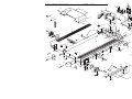
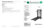
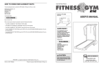
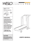
ORDERING REPLACEMENT PARTS
To order replacement parts, contact the ICON Fitness Lifestyle Ltd. office, or write:
ICON Fitness Lifestyle Ltd.
Greenwich House
223 North Street
Sheepscar
Leeds LS7 2AA
West Yorkshire
Tel: Country Code: 0345-089009
Fax: 0113-2411120
When ordering parts, please be prepared to give the following information:
¥ The MODEL NUMBER OF THE PRODUCT (WETL26090)
¥ The NAME OF THE PRODUCT (WESLO CADENCE¨ 935 treadmill)
¥ The SERIAL NUMBER OF THE PRODUCT (see the front cover of this manual)
¥ The KEY NUMBER OF THE PART(S) (see the PART LIST and the EXPLODED DRAWING
attached in the centre of this manual)
¥ The DESCRIPTION OF THE PART(S) (see the PART LIST and the EXPLODED DRAWING
attached in the centre of this manual).
If possible, place the treadmill near your telephone for easy reference when calling.
WESLO is a registered trademark of ICON Health & Fitness, Inc.
Part No. 153695 R0599A
Printed in Canada © 1999 ICON Health & Fitness, Inc.
¨
Class HC Fitness Product
Model No. WETL26090
Serial No.
Write the serial number in the
space above for future reference.
Serial
Number
Decal
QUESTIONS?
As a manufacturer, we are
committed to providing
complete customer satisfaction.
If you have questions, or if
there are missing parts, we will
guarantee complete satisfaction
through our Customer Service
Department.
Please CALL:
0345-089009
Or WRITE:
ICON Fitness Lifestyle Ltd.
Greenwich House
223 North Street
Sheepscar
Leeds LS7 2AA
West Yorkshire
CAUTION
Read all precautions and instructions in this manual before using
this equipment. Save this manual
for future reference.
USER'S MANUAL
TABLE OF CONTENTS
IMPORTANT PRECAUTIONS . . . . . . . . . . . . . . . . . . . . . . . . . . . . . . . . . . . . . . . . . . . . . . . . . . . . . . . . . . . . . 2
BEFORE YOU BEGIN . . . . . . . . . . . . . . . . . . . . . . . . . . . . . . . . . . . . . . . . . . . . . . . . . . . . . . . . . . . . . . . . . . . 4
ASSEMBLY . . . . . . . . . . . . . . . . . . . . . . . . . . . . . . . . . . . . . . . . . . . . . . . . . . . . . . . . . . . . . . . . . . . . . . . . . . . 5
OPERATION AND ADJUSTMENT . . . . . . . . . . . . . . . . . . . . . . . . . . . . . . . . . . . . . . . . . . . . . . . . . . . . . . . . . . 7
HOW TO FOLD AND MOVE THE TREADMILL . . . . . . . . . . . . . . . . . . . . . . . . . . . . . . . . . . . . . . . . . . . . . . . 10
MAINTENANCE AND TROUBLE-SHOOTING . . . . . . . . . . . . . . . . . . . . . . . . . . . . . . . . . . . . . . . . . . . . . . . . 12
CONDITIONING GUIDELINES . . . . . . . . . . . . . . . . . . . . . . . . . . . . . . . . . . . . . . . . . . . . . . . . . . . . . . . . . . . 14
ORDERING REPLACEMENT PARTS . . . . . . . . . . . . . . . . . . . . . . . . . . . . . . . . . . . . . . . . . . . . . . . Back Cover
Note: A PART LIST and an EXPLODED DRAWING are attached in the centre of this manual. Remove the PART
LIST and EXPLODED DRAWING before beginning assembly.
IMPORTANT PRECAUTIONS
WARNING:
To reduce the risk of burns, fire, electric shock, or injury to persons, read
the following important precautions and information before operating the treadmill.
treadmill at a time.
1. It is the responsibility of the owner to ensure
that all users of this treadmill are adequately
informed of all warnings and precautions.
10. Wear appropriate exercise clothing when
using the treadmill. Do not wear loose
clothing that could become caught in the
treadmill. Athletic support clothes are recommended for both men and women. Always
wear athletic shoes. Never use the treadmill
with bare feet, wearing only stockings, or in
sandals.
2. Use the treadmill only as described in this
manual.
3. Place the treadmill on a level surface, with 8
feet (2 m) of clearance behind it. Do not place
the treadmill on a surface that blocks any air
openings. To protect the floor or carpet from
damage, place a mat under the treadmill.
11. When connecting the power cord (see page
7), plug the power cord into an earthed circuit. When replacing the fuse, on ASTA
approved BS1362 type should be fitted to the
fuse carrier. A 13 amp fuse should be used.
No other appliance should be on the same
circuit.
4. When choosing a location for the treadmill,
make sure that the location and position permits access to the plug.
5. Keep the treadmill indoors, away from moisture and dust. Do not put the treadmill in a
garage or covered patio, or near water.
12. If you need an extension cord, use only a 3conductor, 14 gauge (1mm2) cord that is no
longer than 5 feet (1.5) meters.
6. Do not operate the treadmill where aerosol
products are used or where oxygen is being
administered.
13. Keep the power cord and away from heated
surfaces.
7. Keep children under the age of 12 and pets
away from the treadmill at all times.
14. Never move the walking belt whilst the power
is turned off. Do not operate the treadmill if
the power cord or plug is damaged, or if the
treadmill is not working properly. (See
BEFORE YOU BEGIN on page 4 if the treadmill is not working properly.)
8. The treadmill should not be used by persons
weighing more than 250 pounds (115 kg).
9. Never allow more than one person on the
2
SUGGESTED STRETCHES
The correct form for several basic stretches is shown in the
drawings at the right. Move slowly as you stretchÑnever
bounce.
1
1. Toe Touch Stretch
Stand with your knees bent slightly and slowly bend forward
from your hips. Allow your back and shoulders to relax as you
reach down toward your toes as far as possible. Hold for 15
counts, then relax. Repeat 3 times. Stretches: Hamstrings,
back of knees and back.
2
2. Hamstring Stretch
Sit with one leg extended. Bring the sole of the opposite foot
toward you and rest it against the inner thigh of your extended
leg. Reach toward your toes as far as possible. Hold for 15
counts, then relax. Repeat 3 times for both legs. Stretches:
Hamstrings, lower back and groin.
3
3. Calf/Achilles Stretch
4
With one leg in front of the other, reach forward and place
your hands against a wall. Keep your back leg straight and
your back foot flat on the floor. Bend your front leg, lean forward and move your hips toward the wall. Hold for 15 counts,
then relax. Repeat 3 times for both legs. To cause further
stretching of the achilles tendons, bend your back leg as well.
Stretches: Calves, achilles tendons and ankles.
4. Quadriceps Stretch
With one hand against a wall for balance, reach back and
grasp one foot with your other hand. Bring your heel as close
to your buttocks as possible. Hold for 15 counts, then relax.
Repeat 3 times for both legs. Stretches: Quadriceps and hip
muscles.
5. Inner Thigh Stretch
Sit with the soles of your feet together and your knees outward. Pull your feet toward your groin area as far as possible.
Hold for 15 counts, then relax. Repeat 3 times. Stretches:
Quadriceps and hip muscles.
15
5
CONDITIONING GUIDELINES
begin to use stored fat calories for energy. If your goal
is to burn fat, adjust the speed and incline of the treadmill until your heart rate is near the low end of your
training zone. (See pages 7 to 9.)
WARNING:
Before beginning
this or any exercise program, consult your
physician. This is especially important for
individuals over the age of 35 or individuals
with pre-existing health problems.
Aerobic Exercise
If your goal is to strengthen your cardiovascular system, your exercise must be Òaerobic.Ó Aerobic exercise
is activity that requires large amounts of oxygen for
prolonged periods of time. This increases the demand
on the heart to pump blood to the muscles, and on the
lungs to oxygenate the blood. For aerobic exercise,
adjust the speed and incline of the treadmill until your
heart rate is near the middle of your training zone. (See
pages 7 to 9.)
The pulse sensor is not a medical device.
Various factors, including your movement,
may affect the accuracy of heart rate readings.
The sensor is intended only as an exercise aid
in determining heart rate trends in general.
The following guidelines will help you to plan your
exercise program. RememberÑthese are general
guidelines only. For more detailed exercise information, obtain a reputable book or consult your physician.
WORKOUT GUIDELINES
Each workout should include the following three parts:
EXERCISE INTENSITY
Warming Up
Whether your goal is to burn fat or to strengthen your
cardiovascular system, the key to achieving the
desired results is to exercise with the proper intensity.
The proper intensity level can be found by using your
heart rate as a guide. To find the proper heart rate for
you, first find your age at the top of the chart below
(ages are rounded off to the nearest ten years). Next,
find the two numbers below your age. The two numbers are your Òtraining zone.Ó
Start each workout with 5 to 10 minutes of stretching
and light exercise. A proper warm-up increases your
body temperature, heart rate, and circulation in preparation for exercise.
Training Zone Exercise
After warming up, increase the intensity of your exercise until your pulse is in your training zone for 20 to
60 minutes. (During the first few weeks of your exercise program, do not keep your pulse in your training
zone for longer than 20 minutes.) Breathe regularly
and deeply as you exerciseÑnever hold your breath.
Cool-down
Finish each workout with 5 to 10 minutes of stretching
to cool down. This will increase the flexibility of your
muscles and will help prevent post-exercise problems.
To measure your heart rate during exercise, use the
pulse sensor on the console. If your heart rate is too
high or too low, adjust the speed of the treadmill as
needed.
EXERCISE FREQUENCY
To maintain or improve your condition, complete three
workouts each week, with at least one day of rest
between workouts. After a few months, you may complete up to five workouts each week if desired. The
key to success is to make exercise a regular and
enjoyable part of your everyday life.
Fat Burning
To burn fat effectively, you must exercise at a relatively
low intensity level for a sustained period of time.
During the first few minutes of exercise, your body
uses easily accessible carbohydrate calories for energy. Only after the first few minutes does your body
14
able to safely lift 45 pounds (20 kg) in order
to raise, lower, or move the treadmill.
15. Never start the treadmill whilst you are
standing on the walking belt. Always hold the
handrails whilst using the treadmill.
21. When storing the treadmill, make sure that
the storage latch is fully closed.
16. The treadmill is capable of high speeds.
Adjust the speed in small increments to
avoid sudden jumps in speed.
22. Inspect and tighten all parts of the treadmill
every three months.
17. The pulse sensor is not a medical device.
Various factors, including the user's movement, may affect the accuracy of heart rate
readings. The pulse sensor is intended only
as an exercise aid in determining heart rate
trends in general.
23. Never drop or insert any object into any
opening.
24. DANGER: Always unplug the power cord
before performing the maintenance and
adjustment procedures described in this
manual. Never remove the motor hood
unless instructed to do so by an authorised
service representative. Servicing other than
the procedures in this manual should be performed by an authorised service representative only.
18. Never leave the treadmill unattended whilst it
is running. Always remove the key when the
treadmill is not in use.
19. Do not change the incline of the treadmill by
placing objects under the treadmill.
25. This treadmill is intended for in-home use
only. Do not use this treadmill in any commercial, rental, or institutional setting.
20. Do not attempt to raise, lower, or move the
treadmill until it is properly assembled. (See
ASSEMBLY on page 5, and HOW TO MOVE
THE TREADMILL on page 11.) You must be
WARNING:
Before beginning this or any exercise program, consult your physician.
This is especially important for persons over the age of 35 or persons with pre-existing health problems. Read all instructions before using. ICON assumes no responsibility for personal injury or property damage sustained by or through the use of this product.
SAVE THESE INSTRUCTIONS
The decal shown at the right has been
placed on your treadmill. If the decal is
missing, or if it is not legible, please call
our Customer Service Department to order
a free replacement decal (see ORDERING
REPLACEMENT PARTS on the back cover
of this manual). Apply the decal in the
location shown.
3
BEFORE YOU BEGIN
Thank you for selecting the WESLO¨ CADENCE 935
treadmill. The CADENCE 935 treadmill combines
advanced technology with innovative design to let you
enjoy an excellent form of cardiovascular exercise in
the convenience and privacy of your home. And when
youÕre not exercising, the unique CADENCE 935 can
be folded up, requiring less than half the floor space of
other treadmills.
please call our Customer Service Department at 0345089009. To help us assist you, please note the product
model number and serial number before calling. The
model number of the treadmill is WETL26090. The
serial number can be found on a decal attached to the
treadmill (see the front cover of this manual for the
location).
Before reading further, please review the drawing
below and familiarise yourself with the parts that are
labelled.
For your benefit, read this manual carefully before
using the treadmill. If you have additional questions,
Speed Control
Water Bottle Holder
(Bottle not included)
Accessory Tray
Console
Handrails
Key/Clip
Storage Latch
FRONT
Walking Belt
Foot Rails
Circuit Breaker
BACK
Rear Roller
Adjustment Bolts
Incline Leg
4
RIGHT SIDE
PROBLEM: The walking belt is off-centre or slips when walked on
SOLUTION: a. If the walking belt has shifted to the left, first
remove the key and UNPLUG THE POWER CORD.
Using the allen wrench, turn the left rear roller adjustment bolt clockwise, and the right bolt counterclockwise, 1/4 of a turn each. Be careful not to overtighten
the walking belt. Plug in the power cord, insert the
key and run the treadmill for a few minutes. Repeat
until the walking belt is centred.
b. If the walking belt has shifted to the right, first
remove the key and UNPLUG THE POWER CORD.
Using the allen wrench, turn the left rear roller adjustment bolt counterclockwise, and the right bolt clockwise, 1/4 of a turn each. Be careful not to overtighten
the walking belt. Plug in the power cord, insert the
key and run the treadmill for a few minutes. Repeat
until the walking belt is centred.
c. If the walking belt slips when walked on, first
remove the key and UNPLUG THE POWER CORD.
Using the allen wrench, turn both rear roller adjustment bolts clockwise, 1/4 of a turn. When the walking
belt is correctly tightened, you should be able to lift
each side of the walking belt 5 to 7 centimetres off
the walking platform. Be careful to keep the walking
belt centred. Plug in the power cord, insert the key
and run the treadmill for a few minutes. Repeat until
the walking belt is properly tightened.
a
b
c
PROBLEM: The walking belt slows when walked on
SOLUTION: a. If an extension cord is needed, use only a 3-conductor, 14-gauge (1mm2) cord that is no longer
than 5 feet (1.5 meters).
b. If the walking belt is overtightened, treadmill performance may decrease and the walking belt may be
permanently damaged. Remove the key and
UNPLUG THE POWER CORD. Using the allen
wrench, turn both rear roller adjustment bolts counterclockwise, 1/4 of a turn. When the walking belt is
properly tightened, you should be able to lift each
side of the walking belt 5 to 7 centimetres off the
walking platform. Be careful to keep the walking belt
centred. Plug in the power cord, insert the key and
run the treadmill for a few minutes. Repeat until the
walking belt is properly tightened.
b
5Ñ7 cm
Rear Roller
Adjustment Bolts
c. If the walking belt still slows when walked on, please call our Customer Service Department.
13
MAINTENANCE AND TROUBLE-SHOOTING
Most treadmill problems can be solved by following the steps below. Find the symptom that applies, and
follow the steps listed. If further assistance is needed, please call our Customer Service Department.
PROBLEM: The power does not turn on
SOLUTION: a. Make sure that the power cord is plugged into a properly earthed outlet. (See HOW TO PLUG IN
THE POWER CORD on page 7.) If an extension cord is needed, use only a 14-gauge cord of
five feet (1,5m) or less in length.
b. After the power cord has been plugged in, make sure that the key is fully inserted into the console.
c. Check the circuit breaker located on the treadmill
frame near the power cord. If the switch protrudes as shown, the circuit breaker has tripped.
To reset the circuit breaker, wait for five minutes
and then press the switch back in.
c
Reset
Tripped
Tripped
Reset
PROBLEM: The power turns off during use
SOLUTION: a. Check the circuit breaker located on the treadmill frame near the power cord (see the drawing
above). If the circuit breaker has tripped, wait for five minutes and then press the switch back in.
b. Make sure that the power cord is plugged in.
c. Remove the key from the console. Reinsert the key fully into the console.
d. If the treadmill still will not run, please call our Customer Service Department.
PROBLEM: The displays of the console do not function properly
SOLUTION: a. Check the batteries in the console. If the batteries need to be replaced, see assembly step 6 on
page 6. Most problems are the result of drained batteries.
b. If the speed display does not show a correct reading, remove the key and UNPLUG THE POWER
CORD. Remove the screws from the sides and front
of the hood. Carefully remove the hood. Locate the
Reed Switch (19) and the Magnet (18) on the left
side of the Pulley (89). Turn the Pulley until the
Magnet is aligned with the Reed Switch. Make sure
that the gap between the Magnet and the Reed
Switch is about 3mm (1/8Ó). If necessary, loosen
the Screw (44) and move the Reed Switch slightly.
Retighten the Screw. Re-attach the hood and run
the treadmill for a few minutes to check for a correct
speed reading.
12
3mm
19
89
18
44
Top
View
ASSEMBLY
Assembly requires two people. Set the treadmill in a cleared area and remove all packing materials. Do not
dispose of the packing materials until assembly is completed. Note: The underside of the walking belt is coated
with high-performance lubricant. During shipping, a small amount of lubricant may be transferred to the top of the
walking belt or the shipping carton. This does not affect treadmill performance. If there is lubricant on top of the
walking belt, wipe off the lubricant with a soft cloth and a mild, non-abrasive cleaner. The following tools are
required for assembly: a phillips screwdriver
and two adjustable wrenches
(not included).
During assembly, refer to the drawings below to identify the small parts used in assembly.
Console Screw (47)Ð4
Base Leg Nut
(73)Ð4
Flange Nut (9)Ð2
Base Leg Bolt (69)Ð4
Upright Bolt (48)Ð2
Base Leg Washer
(70)Ð6
Latch Screw (49)Ð4
Handrail Bolt (71)Ð2
Upright Washer
(38)Ð2
1. Refer to drawing 2 below. Note that the Console
Base (52) and the Right Handrail (60) are connected
to the treadmill by the Wire Harness (76). During
assembly steps 1 through 3, be careful to avoid
pulling on or damaging the Wire Harness.
1
69
65
70
59
73
67
64
Refer to drawing 1. With the help of a second person, carefully lay the treadmill on its side. Position
one of the Base Legs (64) on the base of the
Upright (59) as shown. Make sure that the Base Leg
Pads (67) and the Front Wheel (65) are in the indicated positions. Attach the Base Leg with two Base
Leg Bolts (69), two Base Leg Washers (70), and two
Base Leg Nuts (73).
With the help of a second person, carefully turn the
treadmill onto its other side. Assemble the other
Base Leg (64) as described above.
73
2
76
With the help of a second person, carefully raise the
treadmill to the upright position so the Base Legs
(64) are resting flat on the floor.
60
2. Hold the treadmill firmly with both hands, and lower
the treadmill to the floor. To decrease the possibility of injury, bend your legs and keep your back
straight.
5
52
3. Insert the bracket on the Left Handrail (61) into the
left Upright (59). Whilst a second person holds the
Console Base (52), carefully insert the Right
Handrail (60) into the right Upright (59). Make sure
that the lower ends of the Handrails (61, 60) are
on the inside of the Base Legs (64) (refer to the
inset drawing).
3
52
76
61
60
Bracket
Loosely thread an Upright Bolt (48) with an Upright
Washer (38) into each Upright (59).
48
38
59
59
Refer to the inset drawing. Insert a Handrail Bolt
(71) with a Base Leg Washer (70) into the right Base
Leg (64) and the Right Handrail (60). Loosely
thread a Flange Nut (9) onto the Handrail Bolt.
Repeat this step with the Left Handrail (not shown).
48
38
60
70
9
71
64
4. Place the Console Base (52) on the Left and Right
Handrails (61, 60). Insert the excess Wire Harness
(not shown) into the top of the right Upright (59), as
you pull the excess Wire Harness (76) out of the
bottom of the Upright (see drawing 6). Attach the
Console Base with four Console Screws (47).
4
52
61
60
47
47
Tighten all parts used in assembly step 3.
59
5. Attach the Left Frame Guide (35) and the Frame
Guide Spacer (14) to the left side of the Frame (87)
with four Latch Screws (49) as shown. Note: Be
careful not to overtighten the Screws. Make sure
that the notched end of the Frame Guide is at the
bottom.
5
35
49
14
Notched End
6. The console requires two "AA" batteries (not included); alkaline batteries are recommended. Open the
Battery Cover (56) as shown. Insert two batteries
into the battery compartment, with the negative (Ð)
ends of the batteries touching the springs. Close
the battery cover, push up on the battery cover tab,
and then push the tab forward as shown in the inset
drawing. Be sure that the tab locks into place.
87
6
56
Battery Cover Tab
Batteries
7. Make sure that all parts are properly tightened before you use the treadmill. Note: Some parts may be
left over after assembly is completed. Save the included allen wrench for adjusting the walking belt. To protect
the floor or carpet from damage, place a mat under the treadmill.
6
HOW TO MOVE THE TREADMILL
Before moving the treadmill, convert the treadmill to the
storage position as described on page 10. Make sure that
the storage latch is locked fully over the frame guide.
1. Hold the upper ends of the handrails. Place one foot on
one of the front wheels as shown.
2. Tilt the treadmill back until it rolls freely on the front
wheels. Carefully move the treadmill to the desired location. Never move the treadmill without tipping it back,
or the base pads may come off. To reduce the risk of
injury, use extreme caution whilst moving the treadmill. Do not attempt to move the treadmill over an
uneven surface.
Base Leg
Front Wheels
3. Place one foot on the base, and carefully lower the treadmill until it is resting in the storage position.
HOW TO LOWER THE TREADMILL FOR USE
1. Hold the upper end of the treadmill with your right hand
as shown. Using your left hand, slide open the storage
latch. Pivot the treadmill until the frame guide and the
foot rail are past the storage latch. If necessary, turn the
incline leg as you raise the treadmill.
Incline
Leg
Storage
Latch
Frame
Guide
2. Hold the treadmill firmly with both hands, and lower the
treadmill to the floor. To decrease the possibility of
injury, bend your legs and keep your back straight.
11
Opened
HOW TO SELECT KILOMETRES AND MILES
Console
The console can display distance and speed in either kilometres or miles. To change the unit of measurement, first
UNPLUG THE POWER CORD. Next, remove the six screws
attaching the console to the console base. Lift the console a
few inches, being careful not to pull on the wires, and turn
the console over. Locate the small switch on the back of the
console. Move the switch upward or downward to select kilometres or miles. Re-attach the console to the console base.
After changing the unit of measurement, remove one of
the batteries from the console for about five seconds
and then reinsert it. This will reset the console.
Screws
Console
Base
Screws
Switch
HOW TO FOLD AND MOVE THE TREADMILL
HOW TO FOLD THE TREADMILL FOR STORAGE
Before folding the treadmill, unplug the power cord.
Caution: You must be able to safely lift 45 pounds (20
kg) in order to raise, lower, or move the treadmill.
1. Hold the treadmill with your hands in the locations shown
at the right. To decrease the possibility of injury, bend
your legs and keep your back straight. As you raise
the treadmill, make sure to lift with your legs rather
than your back. Raise the treadmill about halfway to the
vertical position.
2. Move your right hand to the position shown at the right,
and hold the treadmill firmly. Raise the treadmill until the
storage latch locks over the frame guide. If necessary,
turn the incline leg as you raise the treadmill. Make sure
that the storage latch closes fully over the frame
guide.
To protect the floor or carpet from damage, place a
mat under the treadmill. Keep the treadmill out of
direct sunlight. Do not leave the treadmill in the storage position in temperatures above 30¡ Celsius.
10
Incline
Leg
Storage
Latch
Frame
Guide
Closed
OPERATION AND ADJUSTMENT
THE PERFORMANT LUBETM WALKING BELT
Your treadmill features a walking belt coated with PERFORMANT LUBETM, a high-performance lubricant. IMPORTANT: Never apply silicone spray or other substances to the walking belt or the walking platform. They
will deteriorate the walking belt and cause excessive wear.
HOW TO PLUG IN THE POWER CORD
This product must be earthed. If it should malfunction or
break down, earthing provides a path of least resistance for
electric current to reduce the risk of electric shock. This product
is equipped with a cord having an equipment-earthing conductor
and a earthing plug. Plug one end of the cord into the treadmill.
Plug the power cord into an appropriate outlet that is properly installed and earthed in accordance with all local codes
and ordinances.
DANGER:
Improper connection of the
equipment-earthing conductor can result in an
increased risk of electric shock. Check with a qualified electrician or serviceman if you are in doubt as to
whether the product is properly earthed. Do not modify the plug provided with the productÑif it will not fit
the outlet, have a proper outlet installed by a qualified
electrician.
D
SE
FU
Use only a power cord type H05VV-F with a conductor of at least 1mm2, with a country recognised plug and an
appliance coupler.
HOW TO CHANGE THE INCLINE OF THE TREADMILL
To vary the intensity of your exercise, the incline of the treadmill can be changed.
There are three different incline levels. Before changing the incline, remove
the key and unplug the power cord.
To change the incline of the treadmill, first hold the rear roller endcap with one
hand and raise the back of the treadmill a few inches. Using your other hand,
rotate the incline leg to one of the three incline positions. The inset drawing at the
right shows the incline leg rotated to the Òmax fat burnÓ position. This position is
ideal for maximum fat burning. For a less intense fat burning workout, rotate the
incline leg to the Òfat burnÓ position. For aerobic exercise, rotate the incline leg to
the ÒaerobicÓ position. When you have turned the incline leg to the desired position, lower the treadmill. Make sure that the incline leg is resting flat on the floor.
7
Incline
Leg
DIAGRAM OF THE CONSOLE
Monitor Display
Display
Button
Speed Control
Pulse Display
Mode
Button
Clip
Key
Pulse Sensor
Follow the steps below to operate the console.
CAUTION:
Before operating the
console, read the following precautions.
1
Insert the key fully into the power switch.
Note: Inserting the key will not turn on the displays. The displays will turn on when the display
button is pressed or when the walking belt is
started. If you just installed batteries, the displays
will already be on.
¥ Do not stand on the walking belt when turning on the power.
¥ Always wear the clip (see the drawing
above) whilst operating the treadmill. When
the key is removed from the console, the
walking belt will stop.
2
¥ Adjust the speed in small increments.
Reset the console and start the walking belt.
Move the speed
control to the
RESET position. Note:
Each time the
walking belt is
stopped, the speed control must be moved to
the RESET position before the walking belt
can be re-started.
¥ To reduce the possibility of electric shock,
keep the console dry. Avoid spilling liquids
on the console and use only a sealable
water bottle.
STEP BY STEP CONSOLE OPERATION
Before operating the console, make sure that the
power cord is properly plugged in. (See HOW TO
PLUG IN THE POWER CORD on page 7.) In addition,
make sure that batteries are installed in the console.
(See step 6 on page 6.) If there is a thin sheet of clear
plastic on the console, remove it.
Next, slowly move the speed control until the
walking belt begins to move at slow speed.
Carefully step onto the walking belt and begin
exercising. Change the speed of the walking belt
as desired by moving the speed control.
To stop the walking belt, step onto the foot rails
and move the speed control to the RESET position.
Step onto the foot rails of the treadmill. Next, find the
clip attached to the key (see the drawing above). Slide
the clip onto your waistband.
8
3
Follow your progress with the monitor display.
4
The monitor display
offers six modes that
provide instant exercise feedback:
Measure your pulse, if desired.
When you are not
Pulse
using the pulse
Sensor
sensor, a ÒPÓ will
appear in the pulse
display. To measure your pulse,
stand on the foot
rails and place your
thumb on the pulse sensor as shown. The pulse
sensor is pressure activatedÑfully press it down.
Do not press too hard, or the circulation in
your thumb will be restricted, and your pulse
will not be detected. Next, raise your thumb
slightly until the heartshaped indicator in the
Indicator
pulse display flashes
steadily. Hold your
thumb at this level. After
a few seconds, three
dashes will appear in
the display and your pulse will be shown. Hold
your thumb on the sensor for another 15 seconds
for the most accurate reading.
¥ SpeedÑThis mode shows your speed, in
miles per hour or kilometres per hour.
¥ TimeÑThis mode shows the length of time
you have exercised. Note: If you stop exercising for ten seconds, the time mode will pause.
¥ DistanceÑThis mode shows the total number
of miles or kilometres you have walked or
run, up to 999.
¥ Fat CaloriesÑThis mode shows the approximate number of fat calories you have burned.
(See FAT BURNING on page 14.)
¥ CaloriesÑThis mode shows the approximate
number of calories you have burned.
¥ ScanÑThis mode displays the other five
modes, for five seconds each, in a repeating
cycle.
If the displayed pulse appears to be too high or too
low, or if your pulse is not displayed, lift your thumb
off the sensor and allow the display to reset. Press
down again on the sensor as described above.
When the power is
turned on, the scan
mode will be selected.
One mode indicator
will appear by the
Mode Indicators
scan icon and another
mode indicator will
show which mode is currently displayed.
Make sure that your thumb is positioned as shown,
and that you are applying the proper amount of
pressure to the pulse sensor. Try the sensor several times until you become familiar with it.
Remember to stand still whilst measuring your
pulse.
5
If desired, the speed,
time, distance, fat
calories or calories
mode can be individually selected. Press
the mode button
repeatedly until the
desired mode indicator appears. Make sure that
there is not a mode indicator by the scan icon.
Turn off the power.
To turn off the power, simply wait for about six
minutes. If the walking belt is stationary and the
console buttons are not pressed for six minutes,
the power will turn off automatically.
To reset the display, press the display button.
9
PART LISTÑModel No. WETL26090
Key No.
Qty.
1
2
3
4
5
6
7
8
9
10
11
12
13
14
15
16*
17
18
19
20
21
22
23
24
25
26
27
28
29
30
31
32
33
34
35
36
37
38
39
40
41
42
43
44
45
46
47
48
49
50
51
52*
53
2
6
2
2
2
2
2
3
2
1
14
1
14
1
1
1
1
1
1
1
4
20
2
1
1
1
1
1
1
1
1
1
1
1
1
1
1
11
2
1
1
1
1
4
2
2
7
2
18
1
1
1
1
Description
Incline Leg Bolt
Incline Leg Pad
Incline Leg
Incline Leg Plate
Incline Leg Bushing
Incline Leg Bracket
Foot Rail
8Ó Cable Tie
Flange Nut
Tie Clamp
Screw
Releaseable Cable Tie
Fastener
Frame Guide Spacer
Motor Hood
Motor/Pulley/Flywheel/Fan
Motor Belt
Magnet
Reed Switch
Reed Switch Clip
Hood Anchor
Anchor Screw/Base Pad Screw
Frame Pivot Nut
Motor
Pulley/Flywheel/Fan
Motor Tension Bolt
Motor Tension Washer
Motor Star Washer
Motor Tension Nut
Motor Pivot Bolt
Wire Clip
Controller
Electronics Bracket
Receptacle
Left Frame Guide
Circuit Breaker
Front Roller Adj. Bolt
Upright Washer/Adj. Washer
Upright Spacer
Ground Nut
Console
Motor Pivot Sleeve
Storage Latch
Reed Switch Screw
Cage Nut
Motor Pivot Bushing
Console Screw
Upright Bolt
Hood/Latch Screw
Left Rear Endcap
Choke
Console Base Assembly
Motor Pivot Nut
R0599A
Key No.
Qty.
54
55
56
57
58
59
60
61
62
63
64
65
66
67
68
69
70
71
72
73
74
75
76
77
78
79
80
81
82
83
84
85
86
87
88
89
90
91
92
93
94
95
96
97
#
#
#
#
#
#
#
#
1
1
1
2
1
1
1
1
2
2
2
2
2
4
1
4
8
2
8
4
2
1
1
1
1
1
3
1
1
1
8
1
1
1
1
1
1
1
1
1
1
2
1
2
1
1
1
1
1
1
1
1
Description
Speed Control Knob
Speed Potentiometer
Battery Cover
Belt Guide
Key/Clip
Upright
Right Handrail
Left Handrail
Frame Pivot Bolt
Wheel Nut
Base Leg
Front Wheel
Wheel Bolt
Base Leg Pad
Allen Wrench
Base Leg Bolt
Base Leg Washer
Handrail Bolt
Walking Platform Screw
Base Leg Nut
Base Leg Cap
Upright Grommet
Wire Harness
Ground Screw
Latch Decal
Ground Washer
Nylon Washer
Right Rear Endcap
Interface Bracket
Belly Pan
Isolator
Rear Belly Pan
Right Frame Guide
Frame
Incline Rod
Front Roller/Pulley
Walking Platform
Walking Belt
Filter
Rear Roller
Ground Wire
Rear Roller Guard
Console Plug
Rear Roller Adj. Bolt
14Ó White Wire, Male/Female
8Ó White Wire, 2 Female
10Ó Upright Wire Harness
4Ó Black Wire, 2 Female
8Ó Black Wire, 2 Female
4Ó Green/Yellow Ring/Female
8Ó Green/Yellow Ring/Female
UserÕs Manual
Note: Ò#Ó indicates a non-illustrated part. Specifications are subject to change without notice. See the back cover of
the userÕs manual for information about ordering replacement parts.
REMOVE THIS EXPLODED DRAWING
AND PART LIST FROM THE MANUAL
34
Save this EXPLODED DRAWING and PART LIST for future reference.
Note: Specifications are subject to change without notice. For information
about ordering replacement parts, see the back cover of the UserÕs Manual.
11
EXPLODED DRAWINGÑModel No. WETL26090
R0599A
16*
4
49
11
11
49
51
25
52*
17
32
11
12
22
47
30
15
10
41
24
92
49
8
19
18
38
7
75
46
44
20
1
21
80
29
23
22
23
4
84
38
37
49
45
89
3
42
80 27
90
49
2
47
34
28
2
11
31
21
72
2
36
33
22
91
72
3
11
43
46
26
22
5
38
35
95
39
14
72
7
83
82
6
21
22
57
22
22
95
93
44
85
62
79
78
13
68
61
84
38
13
97
87
13
50
49
5
86
13
88
81
44
38
38
13
97
94
69
4
65
73
2
77
6
1
22
66
71
70
79
2
38
3
67
70
22
64
2
74
67
22
63
9
40
11
11
16*
4
11
49
51
25
55
52*
17
54
96
47
32
56
11
22
30
15
47
21
41
24
92
49
19
20
18
75
46
44
80
29
36
33
22
11
72
23
28
22
38
76
37
49
45
89
42
80 27
91
72
47
47
34
23
90
48
31
21
84
38
11
47
43
46
48
58
38
26
22
39
7
83
82
21
22
57
22
44
85
62
13
60
79
61
22
84
59
39
13
87
49
5
86
13
88
69
4
38
13
66
62
65
71
70
67
70
63
9
40
67
22
9
70
69
74
67
22
66
76
22
64
2
64
79
2
38
63
77
1
3
65
73
73
2
6
22
79
73
74
67
70
71
22