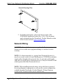
1
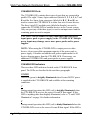
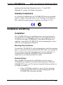
Crestron C2N-HBLOCK Multi-Type Network Distribution Block Operations & Installation Guide This document was prepared and written by the Technical Documentation department at: Crestron Electronics, Inc. 15 Volvo Drive Rockleigh, NJ 07647 1-888-CRESTRON All brand names, product names and trademarks are the property of their respective owners. ©2003 Crestron Electronics, Inc. Crestron C2N-HBLOCK Multi-Type Network Distribution Block Contents Multi-Type Network Distribution Block: C2N-HBLOCK 1 Introduction......................................................................................1 Specifications.........................................................................2 Physical Description ..............................................................2 Industry Compliance..............................................................5 Installation and Wiring ....................................................................5 Installation .............................................................................5 Network Wiring .....................................................................6 Connecting the C2N-HBLOCK to Cresnet Devices .............8 Problem Solving...............................................................................9 General Troubleshooting .......................................................9 Y and Z LED Illumination.....................................................9 Further Inquiries ..................................................................10 Future Updates.....................................................................10 Return and Warranty Policies ........................................................11 Merchandise Returns / Repair Service .......................11 CRESTRON Limited Warranty ...................................11 Operations & Installtion Guide – DOC. 8157A Contents • i Crestron C2N-HBLOCK Multi-Type Network Distribution Block Multi-Type Network Distribution Block: C2N-HBLOCK Introduction The C2N-HBLOCK is a Crestron control network (Cresnet) multiple connector type, network distribution block that provides wiring for up to 15 devices and/or peripherals. The C2N-HBLOCK provides 24 volts direct current (VDC), Cresnet Y and Z data signals, and ground through three different types of Cresnet connectors. Using any one of the connectors as an input source, the remaining connectors may be used as outputs to other equipment. The C2N-HBLOCK contains light-emitting diode (LED) indicators that monitor the input power and input data signals. Functional Summary • Provides wiring for up to 15 devices and/or peripherals • Three different types of Cresnet connectors, all of which are in parallel - Eight 3.5mm 4-pin screw terminal connectors (mini Cresnet) - Five 5mm 4-pin screw terminal connectors (standard Cresnet) - Three 6-pin RJ11 modular connectors • Two LEDs enable user to diagnose wiring problems Operations & Installation Guide – DOC. 8157A Multi-Type Network Distribution Block • 1 Multi-Type Network Distribution Block Crestron C2N-HBLOCK Specifications The table below provides a summary of specifications for the C2N-HBLOCK. Specifications of the C2N-HBLOCK SPECIFICATION DETAILS Height: 1.27 in (3.23 cm) Width: 5.55 in (14.10 cm) Depth: 3.30 in (8.38 cm) Weight: 0.68 lb (0.31 kg) * Dimensions & Weight * The weight listed is for the C2N-HBLOCK and all supplied 4-pin connectors. Physical Description The C2N-HBLOCK, shown below and on the next page, is housed in a black enclosure with silk-screened labels. The front panel contains 16 connectors that are used to input power and Cresnet data signals to the C2N-HBLOCK and output the same to Cresnet devices. All connectors are internally wired together in parallel. Although not shown, all 4-pin connectors used to attach the Cresnet wiring to the C2N-HBLOCK are supplied but Crestron modular cables are not. The large rear panel has holes and serves as a mounting plate. C2N-HBLOCK 2 • Multi-Type Network Distribution Block Operations & Installation Guide – DOC. 8157A Crestron C2N-HBLOCK Multi-Type Network Distribution Block C2N-HBLOCK Physical Views 1 2 3 24 Y Z G 4 5 24 Y Z G 6 CRESTRON A B C D 8 24 Y Z G POWER Y Z a b c 3.30 in (8.38 cm) E 24 24 24 Y Y Y Z Z Z G G G C2N-HBLOCK 7 24 Y Z G 4.30 in (10.92 cm) ALL CONNECTORS ARE IN PARALLEL 5.55 in (14.10 cm) Front Panel View 6.55 in (16.64 cm) Bottom View C000000 ZA11736 MADE IN THE U.S.A. C2N-HBLOCK N11785 1.33 in (3.38 cm) There are three LEDs on the front panel of the C2N-HBLOCK. The LED labeled POWER illuminates when 24VDC is attached to one connector and is available at the remaining connectors. The Y and Z data signal LEDs are used to diagnose wiring problems of the data signal input to the C2N-HBLOCK. Refer to “Y and Z LED Illumination” on page 9 for further information. The C2N-HBLOCK mounting plate allows the unit to be installed into any location that is convenient for Cresnet wiring. The mounting plate can be removed to install the C2N-HBLOCK onto the CNXRMAK, Crestron Rack Mount Kit (not supplied). The CNXRMAK is then installed into a standard 19-inch wide equipment rack. Refer to “Rack Installation” on page 5 for details. NOTE: The CNXRMAK occupies two rack spaces (2U). Operations & Installation Guide – DOC. 8157A Multi-Type Network Distribution Block • 3 Multi-Type Network Distribution Block Crestron C2N-HBLOCK C2N-HBLOCK Ports The C2N-HBLOCK contains three types of ports that are connected in parallel. The eight 3.5mm, 4-pin connectors (labeled 1, 2, 3, 4, 5, 6, 7 and 8) and the five 5mm, 4-pin connectors (labeled A, B, C, D and E) are used to connect the C2N-HBLOCK to other four-wire Cresnet devices. The three 6-pin RJ11 modular ports (labeled a, b and c) are used to connect the C2N-HBLOCK to modular devices in the Cresnet system. Only one port (any of the three types) is used as an input source and the remaining ports are used as outputs. CAUTION: Do not connect or daisy-chain more than one power input (power pack or power supply) to the C2N-HBLOCK. Multiple power inputs may damage one or more power packs and/or power supplies. NOTE: When using the C2N-HBLOCK to output power to other devices, do not exceed the maximum capacity of the power pack or power supply. Calculate and add the total power requirements for all devices drawing power from the C2N-HBLOCK. If necessary, use additional C2N-HBLOCKs and power packs or power supplies. C2N-HBLOCK Indicators There are three LED indicators located on the C2N-HBLOCK front panel. The LEDs are described in the next three paragraphs. POWER This LED (green) is brightly illuminated when Cresnet 24VDC power is supplied to the C2N-HBLOCK and available at the remaining connectors. Y During normal operation, this LED (red) is brightly illuminated when the C2N-HBLOCK receives the correct Cresnet Y data signal. If this LED is anything other than brightly illuminated, refer to “Y and Z LED Illumination” on page 9 for further information. Z During normal operation, this LED (red) is dimly illuminated when the C2N-HBLOCK receives the correct Cresnet Z data signal. If this LED is 4 • Multi-Type Network Distribution Block Operations & Installation Guide – DOC. 8157A Crestron C2N-HBLOCK Multi-Type Network Distribution Block anything other than dimly illuminated, refer to “Y and Z LED Illumination” on page 9 for further information. Industry Compliance As of the date of manufacture, the C2N-HBLOCK has been tested and found to comply with specifications for CE marking and standards per EMC and Radiocommunications Compliance Labelling (N11785). Installation and Wiring Installation The C2N-HBLOCK may be installed into any convenient location by securing the unit’s mounting plate with screws (not supplied) or into a 19-inch rack by using a CNXRMAK, Crestron Rack Mount Kit (not supplied). To install the C2N-HBLOCK via the mounting plate or into a rack, refer to the appropriate subsection. Mounting Plate Installation To install the C2N-HBLOCK via the mounting plate, attach the mounting plate to a convenient location and anchor the unit with a screw through at least one hole in each corner (mounting screws are not supplied). It is recommended to install the C2N-HBLOCK in an area where the connectors are accessible and LEDs are visible. Rack Installation The C2N-HBLOCK may also be installed into a rack by using a CNXRMAK (not supplied). Perform the following steps to install the C2N-HBLOCK into a rack. The only tool required for this procedure is a #2 Phillips screwdriver. 1. Using a #2 Phillips screwdriver, remove the four mounting screws (shown below) that secure the mounting plate to the C2N-HBLOCK and remove the plate. Operations & Installation Guide – DOC. 8157A Multi-Type Network Distribution Block • 5 Multi-Type Network Distribution Block Crestron C2N-HBLOCK Detach Mounting Plate 2. For further instructions, refer to the latest revision of the CNXRMAK Installation Guide (Doc. 8156). This document can be obtained from the Downloads | Product Manuals section of the Crestron website (www.crestron.com). Network Wiring CAUTION: Use only Crestron power supplies for Crestron equipment. Failure to do so could cause equipment damage or void the Crestron warranty. NOTE: For larger networks (i.e., greater than 28 network devices), it may be necessary to add a Cresnet Hub/Repeater (CNXHUB) to maintain signal quality throughout the network. Also, for networks with lengthy cable runs or varying types of network devices, it may be desirable to add a hub/repeater after only 20 network devices. NOTE: When installing network wiring, refer to the latest revision of the wiring diagram(s) appropriate to your specific system configuration, available from the Downloads | Product Manuals | Wiring Diagrams section of the Crestron website (www.crestron.com). 6 • Multi-Type Network Distribution Block Operations & Installation Guide – DOC. 8157A Crestron C2N-HBLOCK Multi-Type Network Distribution Block When calculating the wire gauge for a particular Cresnet run, the length of the run and the power factor of each network unit to be connected must be taken into consideration. If Cresnet units are to be daisy-chained on the run, the power factor of each unit to be daisy-chained must be added together to determine the power factor of the entire chain. If the unit is a home-run from a Crestron system power supply network port, the power factor of that unit is the power factor of the entire run. The length of the run in feet and the power factor of the run should be used in the resistance equation on the next page to calculate the value on the right side of the equation. Resistance Equation R < 40,000 L x PF Where: R = Resistance (refer to table below). L = Length of run (or chain) in feet. PF = Power factor of entire run (or chain). The required wire gauge should be chosen such that the resistance value is less than the value calculated in the resistance equation. Refer to the table after this paragraph. Wire Gauge Values RESISTANCE (R) WIRE GAUGE 4 16 6 18 10 20 15 22 13 Doubled CAT5 8.7 Tripled CAT5 NOTE: All Cresnet wiring must consist of two twisted-pairs. One twisted pair is the +24V conductor and the GND conductor and the other twisted pair is the Y conductor and the Z conductor. NOTE: When daisy-chaining Cresnet units, strip the ends of the wires carefully to avoid nicking the conductors. Twist together the ends of the wires that share a pin on the network connector, and tin the twisted connection. Apply solder only to the ends of the twisted wires. Avoid tinning too far up the wires or the end becomes brittle. Insert the tinned Operations & Installation Guide – DOC. 8157A Multi-Type Network Distribution Block • 7 Multi-Type Network Distribution Block Crestron C2N-HBLOCK connection into the Cresnet connector and tighten the retaining screw. Repeat the procedure for the other three conductors. Connecting the C2N-HBLOCK to Cresnet Devices CAUTION: Do not connect or daisy-chain more than one power input (power pack or power supply) to the C2N-HBLOCK. Multiple power inputs may damage one or more power packs and/or power supplies. CAUTION: Crestron modular cables are rated for a maximum of two (2) amperes. Do not exceed this current capacity for any modular device. If more current is required, connect an appropriate external power pack to the modular device. NOTE: When using the C2N-HBLOCK to output power to other devices, do not exceed the maximum capacity of the power pack or power supply. Calculate and add the total power requirements for all devices drawing power from the C2N-HBLOCK. If necessary, use additional C2N-HBLOCKs and power packs or power supplies. NOTE: When installing network wiring, refer to the latest revision of the wiring diagram(s) appropriate to your specific system configuration, available from the Downloads | Product Manuals | Wiring Diagrams section of the Crestron website (www.crestron.com). NOTE: Use only Crestron modular cables when making connections to the C2N-HBLOCK modular ports. DO NOT use standard, modular 6-conductor telephone cables. Most telephone cables are wired in a crisscross fashion and are not compatible with Crestron equipment. 8 • Multi-Type Network Distribution Block Operations & Installation Guide – DOC. 8157A Crestron C2N-HBLOCK Multi-Type Network Distribution Block Problem Solving General Troubleshooting The table after this paragraph provides corrective action for possible trouble situations. If further assistance is required, please contact a Crestron customer service representative. C2N-HBLOCK General Troubleshooting POSSIBLE CAUSE(S) CORRECTIVE ACTION C2N-HBLOCK is not receiving power. Y and Z data wires incorrect. Confirm that proper power is supplied to the C2N-HBLOCK (24 VDC regulated). Refer to the "Y and Z LED Illumination" section that follows. TROUBLE POWER LED does not illuminate. Y data LED not brightly illuminated. Z data LED not dimly illuminated. Y and Z LED Illumination The combination of the Y and Z data LEDs, and their brightness of illumination (bright, dim, and off), indicate whether the input data signals to the C2N-HBLOCK are correct. Refer to the table after this paragraph for LED illuminations and the associated data signal conditions. NOTE: The Y and Z data LEDs are provided to denote errors with the data signal inputs to the C2N-HBLOCK. The LEDs do not indicate problems that exist in the output wiring from the C2N-HBLOCK to other devices. C2N-HBLOCK Data Signal LED Troubleshooting Y Bright Off Bright Off Dim Z Dim Bright Bright Dim Bright DATA SIGNAL CONDITIONS Both Y and Z data signals present. Both data signals missing. Y data signal is present, Z is missing. Z data signal is present, Y is missing. Y and Z data signals reversed. Operations & Installation Guide – DOC. 8157A Multi-Type Network Distribution Block • 9 Multi-Type Network Distribution Block Crestron C2N-HBLOCK Further Inquiries If after reviewing this Operation & Installation Guide, you cannot locate specific information or have questions, please take advantage of Crestron's award winning customer service team by calling: • In the US and Canada, call Crestron’s corporate headquarters at 1-888-Crestron [1-888-273-7876]. • In Europe, call Crestron International at +32-15-50-99-50. • In Asia, call Crestron Asia at +852-2341-2016. • In Latin America, call Crestron Latin America at +5255-5093-2160. • In Australia and New Zealand, call Crestron Pacific at +613-9480-2999. Future Updates As Crestron improves functions, adds new features, and extends the capabilities of the C2N-HBLOCK, additional information may be made available as manual updates. These updates are solely electronic and serve as intermediary supplements prior to the release of a complete technical documentation revision. Check the Crestron website (www.crestron.com) periodically for manual update availability and its subjective value. Updates are available from the Downloads | Product Manuals section and are identified as an “Addendum” in the Download column. 10 • Multi-Type Network Distribution Block Operations & Installation Guide – DOC. 8157A Crestron C2N-HBLOCK Multi-Type Network Distribution Block Return and Warranty Policies Merchandise Returns / Repair Service 1. No merchandise may be returned for credit, exchange, or service without prior authorization from CRESTRON. To obtain warranty service for CRESTRON products, contact the factory and request an RMA (Return Merchandise Authorization) number. Enclose a note specifying the nature of the problem, name and phone number of contact person, RMA number, and return address. 2. Products may be returned for credit, exchange, or service with a CRESTRON Return Merchandise Authorization (RMA) number. Authorized returns must be shipped freight prepaid to CRESTRON, Cresskill, N.J., or its authorized subsidiaries, with RMA number clearly marked on the outside of all cartons. Shipments arriving freight collect or without an RMA number shall be subject to refusal. CRESTRON reserves the right in its sole and absolute discretion to charge a 15% restocking fee, plus shipping costs, on any products returned with an RMA. 3. Return freight charges following repair of items under warranty shall be paid by CRESTRON, shipping by standard ground carrier. In the event repairs are found to be non-warranty, return freight costs shall be paid by the purchaser. CRESTRON Limited Warranty CRESTRON ELECTRONICS, Inc. warrants its products to be free from manufacturing defects in materials and workmanship under normal use for a period of three (3) years from the date of purchase from CRESTRON, with the following exceptions: disk drives and any other moving or rotating mechanical parts, pan/tilt heads and power supplies are covered for a period of one (1) year; touchscreen display and overlay components are covered for 90 days; batteries and incandescent lamps are not covered. This warranty extends to products purchased directly from CRESTRON or an authorized CRESTRON dealer. Purchasers should inquire of the dealer regarding the nature and extent of the dealer's warranty, if any. CRESTRON shall not be liable to honor the terms of this warranty if the product has been used in any application other than that for which it was intended, or if it has been subjected to misuse, accidental damage, modification, or improper installation procedures. Furthermore, this warranty does not cover any product that has had the serial number altered, defaced, or removed. This warranty shall be the sole and exclusive remedy to the original purchaser. In no event shall CRESTRON be liable for incidental or consequential damages of any kind (property or economic damages inclusive) arising from the sale or use of this equipment. CRESTRON is not liable for any claim made by a third party or made by the purchaser for a third party. CRESTRON shall, at its option, repair or replace any product found defective, without charge for parts or labor. Repaired or replaced equipment and parts supplied under this warranty shall be covered only by the unexpired portion of the warranty. Except as expressly set forth in this warranty, CRESTRON makes no other warranties, expressed or implied, nor authorizes any other party to offer any warranty, including any implied warranties of merchantability or fitness for a particular purpose. Any implied warranties that may be imposed by law are limited to the terms of this limited warranty. This warranty statement supercedes all previous warranties. Trademark Information All brand names, product names, and trademarks are the sole property of their respective owners. Windows is a registered trademark of Microsoft Corporation. Windows95/98/Me/XP and WindowsNT/2000 are trademarks of Microsoft Corporation. Operations & Installation Guide – DOC. 8157A Multi-Type Network Distribution Block • 11 Crestron Electronics, Inc. 15 Volvo Drive Rockleigh, NJ 07647 Tel: 888.CRESTRON Fax: 201.767.7576 www.crestron.com Operations & Installation Guide – DOC. 8157A 05.03 Specifications subject to change without notice.