1
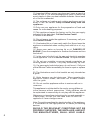
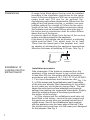
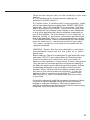
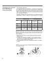
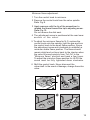
This cooktop is for use with Natural Gas and Universal LPG
PCL755FAU
PCK755FAU
Robert Bosch Hausgeräte GmbH
Carl-Wery-Straße 34
81739 München
Cod. 9000298631 A
Internet:: http://www.bosch-hausgeraete.de
Dear customer,
We would like to thank and congratulate you for your choice.
This practical modern appliance has been made using materials of
the highest quality, which have been put through the strictest of
Quality Controls during manufacture and meticulously tested to
ensure that they meet all of your cooking demands.
We kindly ask you to read and follow these simple instructions
in order to guarantee first-class results from the very start. This
booklet contains important information not only concerning use,
but also concerning your own personal safety and maintenance of
the appliance.
Our products need to be carefully packed to protect them during
transportation. All the material used for packing is considered
essential for this purpose and is also completely recyclable. You
too can contribut towards protecting the environment by disposing
of this material at your nearest recyclable refuse collection point.
Do not dispose of used cooking oil down the kitchen sink. Oil may
seriously damage the environment. Dispose of it in a closed container
at your nearest collection point or, failing this, dispose of it in your
rubbish bin. Although this last solution is far from perfect, your oil
will be taken to a controlled refuse dump where it will not be allowed
to pollute water. You and your children will appreciate it.
Render your old appliance useless before disposing of it at your
nearest recyclable refuse collection centre.
Your local authority will be pleased to inform you where your nearest
centre is.
2
CONTENT
Safety considerations
For your safety
What to do if yo smell gas
Warnings
Installation
Preparing to install
Clearances
Installation of cooktop into Kitchen bench
Installation procedure
Connection
Electrical connection
Gas connection
Conversion front Nat. Gas to Universal LPG
To change injectors
Injector size chart
Minimum flame adjustment
Operating instructions
Burner location
Burner ignition & control
User instructions
Warnings concerning cooking
Cleaning and maintenance
Service
Trouble shooting
Wiring diagram
3
4
4
4
4
6
6
7
7
8
9
9
10
11
11
12
12
13
13
13
14
16
17
18
18
19
Safety considerations
For your safety
• If the information in this manual is not followed exactly, a
fire or explosion may result causing property damage, personal
injury or death.
• Do not store articles on or against this appliance.
• Do not store flammable material near this appliance.
• Do not spray aerosols in the vicinity of this appliance while
it is in operation.
What to do if you
smell gas
• Do not try to light the appliance.
• Do not touch any electrical switch; do not use any phone
in your building.
• Inmediately call your gas supplier from a neighbour’s phone.
Follow the gas supplier’s instructions.
• If you cannot reach your gas supplier , call the fire department.
• Installation and service must be performed by an authorised
person.
Warnings
1. Do not allow the flame to extend beyond the edge of the
cooking utensil. This instruction is based on safety considerations.
2. Do not forget that the unit becomes hot when in use.
Common sense is important. Just because the flame is out,
does not mean parts cannot still be hot.
3. This appliance shall not be used for space heating.
This instruction is based on safety considerations.
4. Be sure to disconnect the electrical supply before disassembly of the appliance.
5. Keep the appliance area clear and free from combustible
materials, gasoline and other flammable vapours and liquids.
6. This appliance must be installed in a position with the proper
level of ventilation. Do not obstruct the flow of combustion and
ventilation air.
7. Cabinets installed above the gas cooktop must have a
minimum clearance of 650 mm (24”).
8. The gas pressure regulator supplied with the appliance
must be installed in line with the gas pipe. (N.G. only)
9. For pressure testing in excess of 3.5 kPa (1/2 psig) the
appliance and its individual shutoff valve must be disconnected
from the gas suply piping system.
4
10. Important. When using a very large pot, leave a gap of at
least 50 mm (2”) to avoid damaging any parts in bench top
wood, plastic or other non-heat resistant materials. Never leave
oil or hot fat unattended.
11.The surfaces on heating and cooking appliances get hot
when in use. Be careful. Keep children away from the
appliance.
12.Only use your appliance for the preparation of food and
never for room-heating purposes.
13.This appliance leaves the factory set for the gas supply
indicated on the data label. Call the Service Centre
if it needs to be altered.
14. Do not tamper inside the appliance. If necessary, call your
local Service Centre.
15. Overheated fat or oil can easily catch fire. Never leave the
appliance unattended when cooking food with fat or oil, e.g.
chips.
16. Never pour water on burning fat or oil. DANGER OF
BURNS! Cover the receptacle to smother the flames and turn
the hob off.
17. In the event of a fault, cut the gas and electricity supplies
to the appliance. Call our Service Centre to repair the fault.
18. Do not use unstable or uneven-based receptacles on
cooking plates or burners. They may accidentally tip over.
19. If a gas supply knob/valve jams, do not force it. Call your
official Service Centre immediately for them to repair or replace
it.
20. The illustrations used in this booklet are only intended as
a guide.
21. Grids become very hot during use. When operating the
appliance control knobs, take care not to make contact
with the grids.
22. Do not use this appliance neither in marine craft nor in
caravans.
This appliance is not intented for the use by young children or
infirm persons without supervision. Young children should
be supervised to ensure they do not play with this appliance.
Make sure you keep these instructions for use and assembly in
a safe place, so that you can hand them on with the
appliance if it ever changes owner.
Note: To avoid jeopardising the electrical safety of the appliance,
it is forbidden to use high-pressure or steam jet cleaning
devices.
SHOULD THE RELEVANT CONDITIONS NOT BE
PROPERLY SATISFIED, THE INSTALLER, AND NOT
THE MANUFACTURER, SHALL HELD LIABLE.
5
Installation
Statutory
requirements
This installation must conform with the following:
• Manufacturer’s Installation instructions
• Local Gas Fitting Regulations
• Municipal Building Codes,
• AGA Installation Code for Gas Burning Appliances.
(AS 5601 - 2004 - Gas Installations).
• S.A.A. Wiring Code
• Local Electrical Regulations
• Any other statutory regulations
Refer to the AGA Installation Code for piping size details.
These built-in hobs are intended to be inserted in a
benchtop cutout.
Only an officially authorised technician should connect
the appliance.
Before you begin, turn off the gas and electricity supply.
Preparing to
install
Installation dimensions are shown in Fig.1.
NAT GAS
Universal LPG
30
Universal LPG
NAT GAS
30
Pressure
test point
Pressure
test point
30
ax
/m
60
min 30
n.
min
15
0
min.
1
520
Gas inlet
connection
mi
30
Pressure
test point
Pressure
test point
520
min
80
30
130
130
80
95
30
30
ax
/m
60
Gas inlet
connection
mi
n.
15
0
min.
1a
Before connecting the unit, check whether the local
connection conditions (type of gas) are compatible with
the unit’s setting. Observe any special conditions imposed
by local suppliers (utilities). The specifications of this
cooktop are stated on the data label located on the
bottom of the cooktop base.
A duplicate data label is supplied for adhesion to
an accessible location near the hotplate if the data
label on the base of the hotplate cannot be
accessed when the hotplate is installed.
6
Clearances
A range hood fitted above the top must be installed
according to the installation instructions for the range
hood. A minimum distance of 650 mm is required for a
range hood and 750 mm for an exhaust fan.
Any adjoining wall surface situated within 200mm from the
edge of any hob burner must be a suitable non-combustible material for a height of 150mm for the entire
length of the hob. Any combustible construction above
the hotplate must be at least 650mm above the top of
the burner and no construction shall be within 450mm
above the top of the burner .
A minimum depth of 50mm from the top of the worktop
surface must be provided for the appliance.
If the base of the hotplate can be touched, a protecting
shield must be fitted. This shield must be at least
10mm from the lowest part of the hotplate and must
be capable of withstanding the appliance temperatures.
Minimum thickness of benchtop is 30 mm. See Fig. 2.
2
Installation of
cooktop into the
kitchen bench
7
30 mm
minimum
Installation procedure:
Side clearances: If the distance measured from the
periphery of the nearest burner to any vertical surface
is less than 200 mm, the surface shall be protected in
accordance with clauses 5.12.1.1 & 5.12.1.2 of AS 5601.
1. For cutout dimensions and clearances refer Fig.1-1a
2. a) If the clamps and the selfadhesive seal (lower edge
of the hob) are already fitted (depending on the model),
do not under any circumstance remove them. The seal
keeps the entire work surface watertight and prevents
spilage from leaking into cupboards underneath. Slightly
losen the retaining screws of the clamps positioned at
the bottom of the cooktop.
b) If the clamps and the selfadhesive seal have not
been fitted in the factory, remove the pan support and
the gas burner covers from your cooking hob and turn it
upside down. Now fit the selfadhesive seal supplied
with the appliance onto the lower edge of the hob. Take
the clamps and screw them into the lower point designed
for this purpose. See Fig. 3.
3 3
3. Place the hotplate on top of the bench cut-out and
press down firmly on all edges at the same time to ensure
that the hob is resting on its entire perimeter.
4 .Once the hob is fitted you should turn the clips and
tighten the screw as shown in Fig. 4.
4
8
Installation continued
Connection
Electrical:
An electrical 10 amp socket needs to be within 1 m of the
hotplate to allow electrical connection. The socket must remain
accessible after installation of the appliance.
Important note:
This appliance is connected to the mains (240 VAC) by means
of the connecting lead which must be fixed to the kitchen unit
to prevent it from coming into contact with hot parts of the hob
(or an oven installed underneath) and remain accessible after
installation of the cooktop. When making this connection make
sure that the lead cannot come into contact with hot parts
of the hob.
Important: This appliance must be earthed. When connecting
the cooktop ensure that the earth wire is connected first and
that all wires are connected to the correct terminals.
Gas:
During the planning stage, consider the position of supply
connections.
The hob must be connected to the gas supply with upstream
connection of an isolation valve in accordance with the respectively valid regulations. We recommend that the isolation valve
be fitted prior to the cooktop to enable isolation of cooktop
from gas supply. The valve must be easily accessible at all
times.
To find out the factory set gas type, see bottom of cooktop next
to gas connection.
Remove plastic cap from gas supply line prior to installation.
Fit regulator (N.G.) or a test point (Universal LPG) directly to
the R1/2" connection as per Fig. 5. and Fig. 6.
Direction of gas flow is indicated on the rear of the regulator.
For position of the inlet connection refer Fig.1-1a.
Use pipe compound or thread sealant, properly theaded pipes
and careful assembly procedure so that there is no cross
threading, etc., which might cause damage or leakage.
Make sure that all connections peformed are free of leakage.
In either of the cases, do not move or twist the L-tube from its
factory-set position.
If for some reason, the L-tube should be twisted, it is necessary
to make sure that this area is properly sealed. Make sure that
all connections performed are free of leakage.
The manufacture does not accept any liability for leakage on
connections performed by the installer or if the L-tube is moved
or twisted.
Natural gas connection
Pressure
test point
Universal LPG connection
R 1/2”
R 1/2”
9
5
6
Pressure
test point.
There are two ways to carry out the connection to the main
gas line:
A. The hotplate can be connected with rigid pipe as
specified in AS5601 table 3.1.
B. Flexible Hose: If installing with a hose assembly, install
with a hose assembly that complies with AS/NZS 1869 (AGA
Approved), 10mm ID, class Bor D, no more than 1,2m long
and in accordance with AS5601. Ensure that the hose does
not contact the hot surfaces of the hotplate, oven, dishwasher
or any other appliance that may be installed underneath or
next to the hotplate. The hose should not be subjected to
abrasion, kinking or permanent deformation and should be
able to be inspected along its entire length with the cooktop
in the installed position. Unions compatible with the hose fittings
must be used and all connections tested for gas leaks.
The supply connection point shall be accessible with the
appliance installed.
WARNING: Ensure that the hose assembly is restrained
from accidental contact with the flue outlet of an underbench oven.
Before Leaving- Check all connections for gas leaks with soap
and water. DO NOT use a naked flame for detecting leaks.
Ignite all burners both individually and concurrently to
ensure correct operation of gas valves, burners and ignition.
Turn gas taps to low flame position and observe stability of
the flame for each burner individually and all together. Adhere
the duplicate data plate to an accessible location near the
hotplate. When satisfied with the hotplate, please instruct
the user on the correct method of operation. In case the
appliance fails to operate correctly after all checks have
been carried out, refer to the authorised service provider
in your area.
It should be expressly noted that we cannot accept any liability
for direct or indirect damage caused by wrong connection,
leakage or improper installation. When being repaired, the
appliance must always be disconnected from the mains supply;
if required, notify our customer service.
10
Coverting the cooktop To change injectors
All work involved in installation, setting and adaptation
from Nat.Gas to
to a different gas type must be carried out by authorised
Univcersal LPG
personnel from our Service Centre and must comply
with current regulations and the conditions laid down by
the local gas company.
Request change-over injectors from our customer service
deparment (refer injector chart below for sizes).
Natural Gas
Burner
Small
Universal LPG
Hourly Gas
Consumption
(MJ)
Hourly Gas
Consumption
(MJ)
Injector
size
(mm)
Injector
size
(mm)
4,0
0.90
3,25
0.50
6,5
1.18
11.5
1.55
6,25
9.5
0.67
Large
wok (Center or
Left)
14,0
1.70
13,25
0.97
Medium
0.85
Before conversion the cooktop must be disconnected
from the electricity and gas valves must be turned to the
OFF position.
1 Remove the trivets, burner caps and burner heads.
Refer Fig. 7.
2 Change the injectors using a 7-mm socket wrench
and be sure to tighten them down properly so that
they are fully airtight. Refer Fig. 8 .
3 Re-assemble the burner component parts in reverse
order.
NOTE: it is not necessary to adjust the primary air control
on these burners.
7 mm
67
11
8
Minimum flame adjustment.
1 Turn the control knob to minimum.
2 Remove the control knob from the valve spindle.
Refer Fig. 9 .
3 Apply pressure with the tip of the screwdriver to
release the thread toward the tap's adjusting screw.
Refer Fig.10.
Do not remove the disk seal.
4 The adjustment screw is positioned at the rear lower
section of the valve.
5 To adjust the minimum flame for N.G. replace the
control knob onto the spindle, light the gas and turn
the control knob to the small flame position. Screw
the adjustment screw anti-clockwise to estabilish a
minimum stable flame position. The flame should
remain alight and not burn back to the injector when
the valve is turned quickcly from ‘Full On’ to the
“Minimum flame” position and back a few times.
To adjust the minimum flame position for ULPG the
screw must be fully tightened down clockwise.
6 Refit the control knob. Never dismount the
valve shaft: in the event of damage, change the entire
valve.
9
10
12
Operating instructions
Burner locations
1
3
1
5
5
3
4
2
6
11
Burner ignition &
control
4
6
12
1. Medium burner
4. Small burner
2. Medium burner
5. Rapid burner
3. Wok burner
6. Control Knobs
Depress control knob and turn anti-clockwise to “High
flame”position. Hold the knob down for a few seconds
until the flame ignites. Keep control knob depressed for
a few seconds to activate the flame failure device. If
ignition fails, depress knob again and wait for ignition.
Turn anti-clockwise to set the flame to the desired
intensity.
If ignition fails depress knob and try again. If flame is
not established in 15 seconds release the control
knob and open a door and wait 1 minute before
attempting a new ignition procedure.
All burners are fitted with a flame failure device which
shuts off the gas supply if the flame extinguishes for
any reason. To re-ignite, wait 30 seconds for any unburnt
gas to disperse before repeating the ignition procedure
described above.
To turn off the gas supply to a burner turn the control
knob clockwise to the “OFF” position. (Refer Fig. 1 3 )
Burner
Position
Graphic
13
13
The control knob is used to adjust the flame of the gas
burner.
“Low flame” graphic= lowest output
“High flame” graphic= higest output
If the ignition sparkers are dirty, this makes the burners
harder to light, so you should keep them as clean
as possible. Clean them using a small brush and
remember that the ignition sparkers must be treated
very gently.
User Instructions
Boiling burners
Use “High flame” setting to bring the pan to the boil, then
adjust the flame between “High flame” and “Low flame”
to maintain the required pan temperature.
Important:
The use of a cooktop leads to the production of heat and
moisture in the kitchen .For this reason make sure that
the room is properly ventilated.Keep natural ventilation
openings,
such as windows, open or provide a
mechanical ventilation device(e.g. a range hood or
overhead exhaust fan). An orangy flame is normal and
simply indicates the presence of salt in the atmosphere
(from cooking). If the flame has yellow patches, this is
not a fault (of any kind).
For safety and economic gas usage you should always
use the correct pan on the correct burner.Flames should
not protrude beyond the base of the pan. You will save
energy, time and money by always placing the correct
15..
pan size on the correct gas ring. See fig. 14
14
The chart below gives the correct pan usage for each burner
Burner
Recomended
pan diameter
Minimum
pan diameter
Small burner
100-120 mm.
100 mm.
Medium
burner
Large burner
120-200 mm.
120 mm.
220-260 mm.
220 mm.
Wok burners
_ 220 mm.
>
Wok trivet
Depending on the model, the hotplate is supplied with
an extra wok trivet. This trivet must be used when using
the wok burner for receptacles with diameters of more
than 26 cm diameter, griddle plates and all kinds of
concave receptacles such as woks, etc.
The manufacturer cannot be held responsible for the
non-use or misuse of this additional pan support.
Coffee support
Depending on the model, the hotplate is supplied with
an extra coffee support. This support is for use only
with the small burner when supporting receptacles
with a diameter of less than 10 cm.
The manufacturer cannot be held responsible for the
non-use or misuse of these additional pan supports. 14
Cooking
recommendations
Wok burner
Large
burner
Medium
burner
Small
burner
15
Very high /High
Medium
Boiling, grilling,
browning, and Asian
food (wok).
Steaks, omelettes,
frying.
Reheating and keeping
things hot, cooked and
pre-cooked dishes.
Rice, white Steaming,
sauce and and
ragout.
vegetables.
Reheating, keeping
things hot and making
tasty casseroles.
Defrosting Melting:
and slow butter,
cooking:
chocolate
vegetables and jelly.
fruits and
frozen
products.
Steaming potatoes,
fresh vegetables,
stews and pasta.
Casseroles, rice
pudding and
caramels.
Low
Warnings concerning cooking:
DON'Ts
DOs
Do not use small receptacles on large burners. The
flame should not touch the
sides of receptacles.
Always use suitably sized
receptacles on each burner. This helps avoid excessive gas consumption
and prevents receptacles
from getting tarnished.
Do not cook without lids or
with lids only partially covering receptacles. You are
wasting energy.
Always use lids.
Only use thick-,flat-based
saucepans, frying pans
Do not use receptacles with
and casseroles.
uneven bases. They lengthen cooking times and increase energy consumption.
Do not place receptacles on
burners off centre. They
could tip over.
Do not use wide-based receptacles on the burners
nearest to the controls.
When centred on the burner, they could touch the
controls or raise the temperature in the area. This may
damage the hob.
Do not place receptacles
directly on top of burners.
Always place receptacles in the middle of
burners.
Always place receptacle
on the pans support.
Make sure that the metal
grids and the tops of the
burners are correctly positioned before using them.
Do not use excessive weights or strike the hob with
heavy objects.
Handle receptacles on the
hob with care.
Do not use two burners or
heat sources for a single
recipient.
Do not use baking trays,
earthenware dishes, etc...
at full heat for a long time .
Only use one recipient per
burner. Use the extra
metal grid on the wok
burner.
16
Cleaning and
Cleaning
andmaintenance:
maintenance:
DON'Ts
Do not
not use
use scouring
scouring
powder, over
powder,
over cleaner
cleaner
sprays or
sprays
orabrasive
abrasivepads
pads
that may
that
mayscratch
scratchthe
theglass.
glass.
Never use
Never
use sharp
sharpobjects
objects
such as
such
asknives
knivesororwire
wire
wool
wool
to remove
to
removethe
theremains
remainsofof
food that
food
thathas
hasbecome
becomeenencrusted onto
crusted
ontothe
thesurface.
surface.
DOs
Once the appliance is
cold, clean it with a sponge and soapy water.
Clean the surface of the
heating elements once
they have cooled down,
each time they are used.
Even small amounts of dirt
burn when it is switched
on again.
The burners and pans support must be cleaned regulary to keep them clean.
This is done by submerging them in soaply water
and scrubbing them them
with a non-metal brush to
keep the holes and slits
free from obstruction so
they can give a perfect
flame.
Dry the burner covers
whenever wet or damp.
Grainsof
Grains
ofsand,
sand,which
which
may,
may,
for example,
for
example, come
comefrom
from
cleaning vegetables,
cleaning
vegetables,can
can
scratch the
scratch
theglass
glasssurface.
surface.
After cleaning and drying
the burners, make sure
that the covers are properly in position on the flame
diffuser.
The high
high temperatures
temperaturessuffered
suffered
byby
thethe
cover
cover
on the
on the
triple-flame
triple-flame
burner
burner
ring and
ringthe
and th
stainless steel
stainless
steelparts
parts
onon
your
your
hob
hob
(plate
(plate
rings,
rings,
grease
grease
trays,
trays,
area area
around
around
burners,
burners,
etc) etc
may become
may
becomediscoloured
discoloured
over
over
time.
time.
This
This
is NORMAL.
is NORMAL.
Clean
Clean
them
them
after
after
useuse
withwith
a a
product suitable for stainless steel.
After washing the pans support, dry them thoroughly before cooking with them again.
The presence of droplets of water or dampness at the beginning of the cooking process
may damage the enamel surface.
Be careful with the feet on the metal grids when cleaning them; if they are detached,
the grid may scratch the glass next time it is used.
17
Service
Trouble shooting
chart
What´s wrong
...If none of the electrical
systems work?
It is not always necessary to call the Service Centre. In
some cases, you may be able to solve the problem
yourself. This table contains some useful information.
Important:
Only authorised personnel from the Service Centre are
qualified to work on the main gas and electric systems.
Possible cause
• Power turned off.
• Faulty fuse.
• The automatic circuit breaker
or mains differential has been
triggered.
...If the electronic ignition
system does not work?
•There may be food or cleaning
product particles between the
spark plugs and the burners.
•The burners are wet.
•The burner covers are not
positioned correctly.
...If the flame on the burners is
not evenly distributed?
•The burner components have
not been assembled properly.
Solution
• Turn power on.
• Check the fuse in the
main fuse box and
replace if faulty.
•Check to see if the circuit
breaker or a differential has
been triggered in the mains
supply box.
•The gap between the spark
plug and the burner needs to
be cleaned carefully.
•Dry the burner covers
.
carefully.
•Make sure that the burner
covers are correctly
positioned.
•Put the components in their
correct positions.
• The burners may not be
totally dry.
•Clean the gas ports on the
burners.
•Dry the burners more
thoroughly (be particularly
careful with single-piece
burners).
...If the gas flow does not seem
normal or there is no gas flow
at all?
•The isolation valve is closed.
• Open the isolation valve.
•If the gas is supplied from a
gas bottle, it may be empty.
•Replace the gas bottle with
a full one.
...If the kitchen smells of gas?
•One of the valves has been
left open.
•Check to see if a valve has
been left open.
•Possible leak on the gas bottle.
coupling.
•Check that the coupling on
the gas bottle is in order.
•The control knob has not been
kept pressed in for long
enough.
•Once ignited, keep the
control pressed in for a few
seconds.
•The burner ports are dirty.
•Clean the burner ports.
•The gas ports on the burners
are dirty.
...If the safety cut-off devices
on the different burners do not
work?
Any of the following are considered to be abnormal operation and may require
servicing:
Yellow tipping of the hob burner flame.
Sooting up of cooking utensils.
Burners not lighting properly.
Burners failing to remain alight.
Gas valves, which are difficult to turn in case the appliance fails to operate correctly,
contact the authorised service provider in your area.
18
Wiring diagram
A
C
E
B
A. Switch
B. Blue wire
C. Brown wire
D. Terminal
E. Ignition module
C
Robert Bosch Hausgeräte GmbH
Gas type
Injectors sizes (mm)
LHF
LHR
RHF
RHR
Centre
HGC (MJ)
Electrical compliance
AGA approval number
Preinstalled NG
19
N
D
E-Nr PCL7 55FA U
Test point pressure (kPa)
L
CIF: A-28-893550
NG
1,0
LP
2,75
0,90
1,18
1,18
1,55
1,70
0,50
0,67
0,67
0,85
0,97
4 2, 50
Robert Bosch Hausgeräte GmbH
E-Nr PCK755FAU
FD
38,50
In compliance with AS 3100
7160
Made in Spain
Gas type
CIF: A-28-893550
FD
Test point pressure (kPa)
NG
1,0
LP
2,75
Injectors sizes (mm)
LHC
RHC
CF
CR
1,70
1,55
0,90
1,18
0,97
0,85
0,50
0,67
HGC (MJ)
Electrical compliance
AGA approval number
Preinstalled NG
36,00
32,25
In compliance with AS 3100
7160
Made in Spain