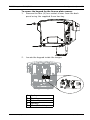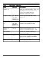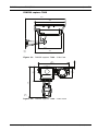
1
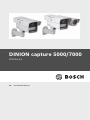
DINION capture 5000/7000
VER Series
en
Installation Manual
DINION capture 5000/7000
Table of Contents | en
3
Table of Contents
1
Safety
5
1.1
Safety precautions
5
1.2
Important safety instructions
6
1.3
Important notices
9
1.4
FCC & ICES compliance
13
1.5
Bosch notices
15
2
Description
16
2.1
Parts List
16
3
Installing the DINION capture
17
3.1
Determining the Range
17
3.2
Determining the Angle
18
3.3
Mounting the DINION capture
20
3.4
Preparing the Wiring
23
3.4.1
Power Input Connections
23
3.4.2
Video Connections
23
3.5
Making the Connections
24
3.6
Automatic Mode Switching
24
4
Configuration
28
4.1
Menus
28
4.1.1
Top level menus
28
4.1.2
Accessing Menu Keys
28
4.1.3
Menu Navigation Keys
31
4.2
Pre-Defined Modes
31
4.3
Day/Night switching (DINION capture 7000)
32
4.4
Camera control communication (Bilinx)
33
4.5
Main menu structure
34
4.5.1
Mode submenu
35
4.5.2
ALC submenu
35
4.5.3
Shutter/AGC submenu
37
4.5.4
Day/Night submenu
4.5.5
(Overview Camera - DINION capture 7000 only)
39
Enhance / Dynamic Engine submenu
41
Bosch Security Systems, Inc.
Installation Manual
| 1.0 | 2012.01
4
en | Table of Contents
4.5.6
DINION capture 5000/7000
Color submenu
(Overview Camera - DINION capture 7000 only)
43
4.5.7
VMD submenu
44
4.6
Install menu structure
45
4.6.1
Language submenu
46
4.6.2
Lens Wizard submenu
46
4.6.3
Alarm I/O submenu
47
4.6.4
Connections submenu
48
4.6.5
Test signal submenu
49
4.6.6
Camera ID submenu
50
4.6.7
Privacy masking submenu
51
4.6.8
Defaults submenu
51
A
Dimensional Drawings
52
| 1.0 | 2012.01
Installation Manual
Bosch Security Systems, Inc.
DINION capture 5000/7000
Safety | en
1
Safety
1.1
Safety precautions
5
DANGER!
High risk: This symbol indicates an imminently hazardous
situation such as "Dangerous Voltage" inside the product.
If not avoided, this will result in an electrical shock, serious
bodily injury, or death.
WARNING!
Medium risk: Indicates a potentially hazardous situation.
If not avoided, this could result in minor or moderate bodily
injury.
CAUTION!
Low risk: Indicates a potentially hazardous situation.
If not avoided, this could result in property damage or risk of
damage to the unit.
NOTICE!
This symbol indicates information or a company policy that
relates directly or indirectly to the safety of personnel or
protection of property.
Bosch Security Systems, Inc.
Installation Manual
| 1.0 | 2012.01
6
en | Safety
1.2
DINION capture 5000/7000
Important safety instructions
Read, follow, and retain for future reference all of the following
safety instructions. Heed all warnings on the unit and in the
operating instructions before operating the unit.
1.
Cleaning - Unplug the unit from the outlet before cleaning.
Follow any instructions provided with the unit. Generally,
using a dry cloth for cleaning is sufficient but a moist, flufffree cloth or leather shammy may also be used. Do not use
aerosol cleaners.
2.
Heat Sources - Do not install the unit near any heat
sources such as radiators, heaters, stoves, or other
equipment (including amplifiers) that produce heat.
3.
Object and liquid entry - Never push objects of any kind
into this unit through openings as they may touch
dangerous voltage points or short-out parts that could
result in a fire or electrical shock. Never spill liquid of any
kind in the unit.
4.
Lightning - For added protection during a lightning storm,
or when leaving this unit unattended and unused for long
periods, unplug the power source and disconnect the
cable system. This will prevent damage to the unit from
lightning and power line surges.
5.
Controls adjustment - Adjust only those controls specified
in the operating instructions. Improper adjustment of
other controls may cause damage to the unit. Use of
controls or adjustments, or performance of procedures
other than those specified, may result in hazardous
radiation exposure.
6.
Overloading - Do not overload circuits. This can cause fire
or electrical shock.
7.
Power cable protection - Protect the power cable from
foot traffic, from being pinched by items placed upon it,
and at cable's exit from the unit.
| 1.0 | 2012.01
Installation Manual
Bosch Security Systems, Inc.
DINION capture 5000/7000
8.
Safety | en
7
Power disconnect - Units have power supplied to the unit
whenever the power cord is inserted into the power
source. The power cord plug is the main power disconnect
device for switching off the voltage for all units.
9.
Power sources - Operate the unit only from the type of
power source indicated on the label. Before proceeding,
be sure to disconnect the power from the cable to be
installed into the unit.
–
For external power supplied units, use only the
recommended or approved power supplies.
–
For limited power source units, this power source
must comply with EN60950. Substitutions may
damage the unit or cause fire or shock.
–
For 24 VAC units, voltage applied to the unit's power
input should not exceed ±10%, or 26.4 VAC. Usersupplied wiring must comply with local electrical
codes (Class 2 power levels). Do not ground the
supply at the terminals or at the unit's power supply
terminals.
–
If unsure of the type of power supply to use, contact
your dealer or local power company.
10. Servicing - Do not attempt to service this unit yourself.
11. Damage requiring service - Unplug the unit from the main
AC power source and refer servicing to qualified service
personnel when any damage to the equipment has
occurred, such as:
–
the power supply cord or plug is damaged;
–
internal exposure to moisture, water, and/or
inclement weather (rain, snow, etc.);
–
liquid has been spilled in the equipment;
–
an object has fallen into the unit;
–
unit has been dropped;
–
unit exhibits a distinct change in performance;
–
unit does not operate normally when the user
correctly follows the operating instructions.
Bosch Security Systems, Inc.
Installation Manual
| 1.0 | 2012.01
8
en | Safety
DINION capture 5000/7000
12. Replacement parts - Be sure the service technician uses
replacement parts specified by the manufacturer, or that
have the same characteristics as the original parts.
Unauthorized substitutions may cause fire, electrical
shock, or other hazards.
13. Safety check - Safety checks should be performed upon
completion of service or repairs to the unit to ensure
proper operating condition.
14. Installation - Install in accordance with the manufacturer's
instructions and in accordance with applicable local codes.
15. Attachments, changes or modifications - Only use
attachments/accessories specified by the manufacturer.
Any change or modification of the equipment, not
expressly approved by Bosch, could void the warranty or,
in the case of an authorization agreement, authority to
operate the equipment.
| 1.0 | 2012.01
Installation Manual
Bosch Security Systems, Inc.
DINION capture 5000/7000
1.3
Safety | en
9
Important notices
Accessories - Do not place this unit on an unstable stand,
tripod, bracket, or mount. The unit may fall and cause serious
injury and/or serious damage to the unit. Use only with the
cart, stand, tripod, bracket, or table specified by the
manufacturer. When a cart is used, use caution and care when
moving the cart/apparatus combination to avoid injury from
tip-over. Quick stops, excessive force, or uneven surfaces may
cause the cart/unit combination to overturn. Mount the unit
per the manufacturer's instructions.
All-pole power switch - Incorporate an all-pole power switch,
with a contact separation of at least 3 mm in each pole, into the
electrical installation of the building. If it is needed to open the
housing for servicing and/or other activities, use this all-pole
switch as the main disconnect device for switching off the
voltage to the unit.
Camera signal - Protect the cable with a primary protector if
the camera signal is beyond 140 feet, in accordance with
NEC800 (CEC Section 60).
NOTICE!
RISK GROUP 1
IR emitted from this product.
This product has been tested according to standard CIE/IEC
62471:2006 “Photobiological safety of lamps and lamp
systems” and found to meet Risk Group 1 for exposure limit
4.3.7 “Infrared radiation hazard exposure limits for the eye.”
For other hazard exposure limits, the product was found to be
exempt. Risk Group 1 is characterized in the standard as
“products are safe for most use applications, except for very
prolonged exposures where direct ocular exposures may be
expected.” Risk Group 1 sources do not pose an infrared
radiation hazard for the eye for times less than 100 s at
distances beyond 200 mm or 8 inches.
Bosch Security Systems, Inc.
Installation Manual
| 1.0 | 2012.01
10
en | Safety
DINION capture 5000/7000
The Exposure Hazard Value for the product (ratio of the
Exposure level to the Exposure limit) is up to 1.8 at a test
distance of 200 mm or 8 inches. The Hazard Distance (distance
beyond which the product falls into the exempt/safe group) is
at most 350 mm or 14 inches. Note that typical operating
distances for license plate capture (3.8 m or 12.5 feet and
greater) are much greater than the Hazard Distance.
When servicing the unit, physically disconnect the power supply
to avoid possible IR exposure to the eyes. If physical
disconnection is not possible, use appropriate shielding to
block the LED panel or use eye protection with a transmission
of 50% or less at a wavelength of 850 nm.
Coax grounding:
–
Ground the cable system if connecting an outside cable
system to the unit.
–
Follow proper safety precautions such as grounding for
any outdoor device connected to this unit.
U.S.A. models only - Section 810 of the National Electrical Code,
ANSI/NFPA No.70, provides information regarding proper
grounding of the mount and supporting structure, grounding of
the coax to a discharge unit, size of grounding conductors,
location of discharge unit, connection to grounding electrodes,
and requirements for the grounding electrode.
Disposal - Your Bosch product was developed and
manufactured with high-quality material and components that
can be recycled and reused. This symbol means that electronic
and electrical appliances, which have reached the end of their
working life, must be collected and disposed of separately
from household waste material. Separate collecting systems
are usually in place for disused electronic and electrical
products. Please dispose of these units at an environmentally
compatible recycling facility, per European Directive 2002/96/
EC
Electronic Surveillance - This device is intended for use in
public areas only. U.S. federal law strictly prohibits
surreptitious recording of oral communications.
| 1.0 | 2012.01
Installation Manual
Bosch Security Systems, Inc.
DINION capture 5000/7000
Safety | en
11
Environmental statement - Bosch has a strong commitment
towards the environment. This unit has been designed to
respect the environment as much as possible.
Electrostatic-sensitive device - Use proper CMOS/MOS-FET
handling precautions to avoid electrostatic discharge.
NOTE: Wear required grounded wrist straps and observe proper
ESD safety precautions when handling the electrostaticsensitive printed circuit boards.
Fuse rating - For protection of the device, the branch circuit
protection must be secured with a maximum fuse rating of 16A.
This must be in accordance with NEC800 (CEC Section 60).
Moving - Disconnect the power before moving the unit. Move
the unit with care. Excessive force or shock may damage the
unit.
Outdoor signals - The installation for outdoor signals, especially
regarding clearance from power and lightning conductors and
transient protection, must be in accordance with NEC725 and
NEC800 (CEC Rule 16-224 and CEC Section 60).
Permanently connected equipment - Incorporate a readily
accessible disconnect device external to the equipment.
Pluggable equipment - Install the socket outlet near the
equipment so it is easily accessible.
Power lines: An outdoor system should not be located in the
vicinity of overhead power lines, electrical lights, or power
circuits, or where it may contact such power lines or circuits.
When installing an outdoor system, extreme care should be
taken to keep from touching power lines or circuits, as this
contact may be fatal.
U.S.A. models only - refer to the National Electrical Code Article
820 regarding installation of CATV systems.
Bosch Security Systems, Inc.
Installation Manual
| 1.0 | 2012.01
12
en | Safety
DINION capture 5000/7000
11-30 VDC / 24 VAC power source: This device is intended to
operate with a limited power source; this power source must
comply with EN60950. The device is designed to operate at
either 11-30 VDC or 24 VAC (if PoE is not available). User
supplied wiring must be in compliance with electrical codes
(Class 2 power levels). If 24 VAC is used, do not ground the
24 VAC supply at the terminals or at the device's power supply
terminals.
Connections: The unit has connection terminals on flying leads.
In wet or outdoor installations use a field wiring box with NEMA
3 or IP55 protection level or better. Make the connections
inside the water tight compartment. After connections are
made ensure that the watertight compartment is tightly closed
and cables and conduits are properly sealed to prevent ingress
of water.
SELV - All the input/output ports are Safety Extra Low Voltage
(SELV) circuits. SELV circuits should only be connected to
other SELV circuits.
Because ISDN circuits are treated like telephone-network
voltage, avoid connecting the SELV circuit to the Telephone
Network Voltage (TNV) circuits.
| 1.0 | 2012.01
Installation Manual
Bosch Security Systems, Inc.
DINION capture 5000/7000
1.4
Safety | en
13
FCC & ICES compliance
FCC & ICES Information
(U.S.A. and Canadian Models Only)
This device complies with part 15 of the FCC Rules. Operation is
subject to the following conditions:
–
this device may not cause harmful interference, and
–
this device must accept any interference received,
including interference that may cause undesired operation.
NOTE: This equipment has been tested and found to comply
with the limits for a Class A digital device, pursuant to Part 15
of the FCC Rules and ICES-003 of Industry Canada. These limits
are designed to provide reasonable protection against harmful
interference when the equipment is operated in a commercial
environment. This equipment generates, uses, and radiates
radio frequency energy and, if not installed and used in
accordance with the instruction manual, may cause harmful
interference to radio communications. Operation of this
equipment in a residential area is likely to cause harmful
interference, in which case the user will be required to correct
the interference at his expense.
Intentional or unintentional modifications, not expressly
approved by the party responsible for compliance, shall not be
made. Any such modifications could void the user's authority to
operate the equipment. If necessary, the user should consult
the dealer or an experienced radio/television technician for
corrective action.
The user may find the following booklet, prepared by the
Federal Communications Commission, helpful: How to Identify
and Resolve Radio-TV Interference Problems. This booklet is
available from the U.S. Government Printing Office,
Washington, DC 20402, Stock No. 004-000-00345-4.
Informations FCC et ICES
(modèles utilisés aux États-Unis et au Canada uniquement)
Ce produit est conforme aux normes FCC partie 15. la mise en
service est soumises aux deux conditions suivantes :
Bosch Security Systems, Inc.
Installation Manual
| 1.0 | 2012.01
14
en | Safety
–
DINION capture 5000/7000
cet appareil ne peut pas provoquer d'interférence nuisible
et
–
cet appareil doit pouvoir tolérer toutes les interférences
auxquelles il est soumit, y compris les interférences qui
pourraient influer sur son bon fonctionnement.
AVERTISSEMENT: Suite à différents tests, cet appareil s’est
révélé conforme aux exigences imposées aux appareils
numériques de Classe A en vertu de la section 15 du règlement
de la Commission fédérale des communications des États-Unis
(FCC). Ces contraintes sont destinées à fournir une protection
raisonnable contre les interférences nuisibles quand l'appareil
est utilisé dans une installation commerciale. Cette appareil
génère, utilise et émet de l'energie de fréquence radio, et peut,
en cas d'installation ou d'utilisation non conforme aux
instructions, générer des interférences nuisibles aux
communications radio. L’utilisation de ce produit dans une
zone résidentielle peut provoquer des interférences nuisibles.
Le cas échéant, l’utilisateur devra remédier à ces interférences
à ses propres frais.
Au besoin, l’utilisateur consultera son revendeur ou un
technicien qualifié en radio/télévision, qui procédera à une
opération corrective. La brochure suivante, publiée par la
Commission fédérale des communications (FCC), peut s’avérer
utile : How to Identify and Resolve Radio-TV Interference Problems
(Comment identifier et résoudre les problèmes d’interférences
de radio et de télévision). Cette brochure est disponible auprès
du U.S. Government Printing Office, Washington, DC 20402,
États-Unis, sous la référence n° 004-000-00345-4.
NOTICE!
This is a class A product. In a domestic environment this
product may cause radio interference, in which case the user
may be required to take adequate measures.
| 1.0 | 2012.01
Installation Manual
Bosch Security Systems, Inc.
DINION capture 5000/7000
1.5
Safety | en
15
Bosch notices
Video loss
Video loss is inherent to digital video recording; therefore,
Bosch Security Systems cannot be held liable for any damage
that results from missing video information. To minimize the
risk of lost digital information, Bosch Security Systems
recommends multiple, redundant recording systems, and a
procedure to back up all analog and digital information.
Copyright
This manual is the intellectual property of Bosch Security
Systems and is protected by copyright. All rights reserved.
Trademarks
All hardware and software product names used in this
document are likely to be registered trademarks and must be
treated accordingly.
Note:
This manual has been compiled with great care and the
information it contains has been thoroughly verified. The text
was complete and correct at the time of printing. The ongoing
development of the products may mean that the content of the
user guide can change without notice. Bosch Security Systems
accepts no liability for damage resulting directly or indirectly
from faults, incompleteness, or discrepancies between the user
guide and the product described.
More information
For more information please contact the nearest Bosch Security
Systems location or visit www.boschsecurity.com
Bosch Security Systems, Inc.
Installation Manual
| 1.0 | 2012.01
16
en | Description
2
DINION capture 5000/7000
Description
The DINION capture is a specialty camera designed to capture
consistent, high-quality images of vehicle license plates.
Available in IP and analog versions, it is ideal for monitoring
parking lots, public areas, and for controlling vehicle access.
The DINION capture overcomes the problems encountered
when using conventional surveillance cameras in vehicle
identification and automatic license plate recognition
applications. The Night Capture Imaging System delivers a
burst of infrared illumination and simultaneously filters out
visible light to ensure clear license plate images in complete
darkness while eliminating the negative effects of headlight
glare.
Advanced Ambient Compensation minimizes plate
overexposure from sunlight for more accurate automatic license
plate recognition. Finally, adjustable imaging modes allow for
fine-tuning the imager for specific regions or license plate
recognition algorithms.
2.1
Parts List
Quantity
Description
1
DINION capture 5000, or
DINION capture 7000
| 1.0 | 2012.01
1
3 mm Hex Key
1
5 mm Hex Key
1
Mounting Template
1
Printed Manual
Installation Manual
Bosch Security Systems, Inc.
DINION capture 5000/7000
3
Installing the DINION capture | en
17
Installing the DINION capture
This section provides instructions for mounting and wiring the
DINION capture.
CAUTION!
The selected mounting location should not place the camera in
a situation where its environmental specifications could be
exceeded.
Ensure the selected location is protected from falling objects,
accidental contact with moving objects, and unintentional
interference from personnel. Follow all applicable building
codes.
3.1
Determining the Range
The DINION capture has a recommended operation range with
specified optimal capture distance for each model as shown
below. Installation should aim to control the traffic through one
lane.
Ranges based on capturing:
520 x 115 mm (approximate) license plates on PAL units
(xER-L2Ry-1)
12 x 6 in. (approximate) license plates on NTSC units
(xER-L2Ry-2)
Field of View at Optimal Capture Distance:
License Plate Camera:
2.8 x 2.1 m (PAL units)
6 ft 6 in. x 4 ft 11 in. (NTSC units)
Overview Camera (DINION capture 7000):
Approximately twice the distance of the License Plate Camera.
Bosch Security Systems, Inc.
Installation Manual
| 1.0 | 2012.01
18
en | Installing the DINION capture
Model
DINION capture 5000/7000
Capture
Optimal
Range
Distance
HFOV
VFOV
VER-x2R1-1
3.8–6.4 m
4.9 m
31.9°
24.2°
VER-x2R1-2
(12.5–21.0 ft)
(16.0 ft)
23.0°
17.3°
VER-x2R2-1
5.5–9.1 m
7.1 m
22.3°
16.8°
VER-x2R2-2
(18–30 ft)
(23.1 ft)
16.0°
12.0°
VER-x2R3-1
7.9–13.7 m
10.2 m
15.6°
11.8°
VER-x2R3-2
(26–45 ft)
(33.5 ft)
11.1°
8.3°
VER-x2R4-1
11.3–19.5 m
14.8 m
10.8°
8.1°
VER-x2R4-2
(37–64 ft)
(48.4 ft)
7.7°
5.8°
VER-x2R5-1
16.5–28.0 m
21.3 m
7.5°
5.6°
VER-x2R5-2
(54–92 ft)
(70.0 ft)
5.3°
4.0°
Note: x = L (DINION capture 5000) or D (DINION capture
7000)
Table 3.1 Ranges for DINION capture 5000 and 7000 Analog Imagers
3.2
Determining the Angle
The maximum mounting angle of the license plate camera to the
car is 40° for speeds up to 160 km/h (100 mph), both
horizontally and vertically. This angle limits the amount of skew
of the letters on the number plate. If the letters are skewed too
much they will start to become unrecognizable and will reduce
automatic software recognition rates.
For maximum performance ensure the mounting angle is as
narrow as possible. To capture vehicle speeds up to 225 km/h
(140 mph) the horizontal and vertical mounting angle should be
less than 30°.
| 1.0 | 2012.01
Installation Manual
Bosch Security Systems, Inc.
DINION capture 5000/7000
Figure 3.1
1
2
3
4
Installing the DINION capture | en
19
Recommended Vertical and Horizontal Mounting Angle
DINION capture
Capture Range
Vertical Mounting Angle
Horizontal Mounting Angle
If the maximum range is exceeded, then the letters become
smaller and more difficult to read. At the maximum range and
angle the width of the number plate covers approximately 12%
of the width of the screen.
NOTICE!
The Capture Range is the distance from the license plate
camera to the license plate. Working below the optimal capture
distance allows a larger area for number plates and more
accurate recognition but less lane area can be covered. If the
imager is too close to the license plate, the plate could
disappear from the field of view before it is captured.
Bosch Security Systems, Inc.
Installation Manual
| 1.0 | 2012.01
20
en | Installing the DINION capture
3.3
DINION capture 5000/7000
Mounting the DINION capture
CAUTION!
Installation should only be performed by a qualified service
professional in accordance with the National Electrical Code or
applicable local codes.
For a secure mounting installation, bolts should extend through
the mounting surface and be secured with nuts, washers, and
lock washers on the opposite side. If studs are used, they
should be anchored in concrete or welded to a steel backer
plate.
Refer to the MBE Mounts and Adapters Installation Guide for
more details about attaching the bracket to an MBE-15 Pole
Mount Adapter or to the MBE-17 Wall Mount Adapter.
1.
Use the wall mount template supplied in the packaging box
2.
Drill four (4) holes for the mounting bolts. If installing
to locate the four mounting holes for the camera bracket.
outdoors, apply a weatherproof sealant around each hole
at the mounting surface.
3.
Route the cable. If routing the cable through the wall, drill
a 25.4 mm (1 in.) hole following the wall mount template
and use a weatherproof sealant to seal around the cable to
ensure a weather tight seal between indoors and outdoors,
otherwise route the cable through one of the side holes in
the mounting bracket by removing the plug and routing the
cable through.
(Routing cables through a side hole in the bracket and into
a near junction box makes setup and troubleshooting
simpler.)
WARNING!
A stud/bolt diameter of 6.0 mm (or 1/4 inch) able to withstand
a 300 kg (660 lb) pull-out force is recommended. The mounting
material must be able to withstand this pull out force.
| 1.0 | 2012.01
Installation Manual
Bosch Security Systems, Inc.
DINION capture 5000/7000
4.
Installing the DINION capture | en
21
Secure the mounting bracket to the mounting surface. Use
four (4) corrosion-resistant, stainless steel studs or bolts,
nuts, washers, and lock washers (not supplied).
5.
Adjust the license plate camera angle using the range and
angle recommendations in Section 3.1 Determining the
Range, page 17.
–
Connect the imager to a local monitor to assist
adjusting the license plate camera.
6.
Adjust the tilt angle of the camera by loosening the tilt bolt
(item 1, below) with the 5 mm hex key and the set screw
(item 2) with a flat head screwdriver.
7.
Place the license plate camera at the desired tilt angle and
tighten the tilt bolt and the set screw.
8.
Adjust the pan angle of the camera by loosening the pan
bolt, located beneath the bracket mounting head, by
loosening the pan bolt using the 5 mm hex key. Place the
license plate camera at the desired pan angle and tighten
the bolt.
Bosch Security Systems, Inc.
Installation Manual
| 1.0 | 2012.01
22
en | Installing the DINION capture
DINION capture 5000/7000
NOTICE!
For purposes of evaluation and testing of the mounting
bracket's integrity under static loading at CSA, the unit was
mounted to a drywall surface as per the procedures below:
–
Locate a stud in the wall and mark the outside edges of the
stud.
–
Using the wall mount bracket as a template, align the
mounting hole with the center of the stud.
–
Mark the point on the wall in the center of the hole where
the mounting bolt will be positioned.
–
Remove the wall mount bracket and drill a pilot hole at the
marked point.
–
Align the wall mount bracket mounting hole with the hole
drilled in the wall.
–
Using a screwdriver, secure the wall mount bracket by
screwing a 2.5 in. screw with washer securely into the
stud.
–
Follow this procedure to attach the three remaining
screws.
NOTICE!
The camera has not been evaluated for safety requirements
using other mounting kits.
| 1.0 | 2012.01
Installation Manual
Bosch Security Systems, Inc.
DINION capture 5000/7000
3.4
Installing the DINION capture | en
23
Preparing the Wiring
CAUTION!
Before proceeding, disconnect the power from the power
supply cable. Ensure that the voltage of the unit matches the
voltage and type of the power supply being used.
The DINION capture 5000 comes pre-wired with a single twowire power input lead and a single 75 ohm coaxial video cable
output lead terminated with a BNC connector. The DINION
capture 7000 comes pre-wired with a single two-wire power
input lead and two 75-ohm coaxial video cables, one cable for
each camera. On all units the video and power wires are
encased in an approximately 2 m long cable, the last 10 cm of
the cable the power and video breaks out separately.
3.4.1
Power Input Connections
A voltage regulator circuit allows for DC or AC operation
between 11-30 VDC and 24 VAC. It also provides protection
from voltage surges, transient spikes, and reversed voltage.
Connect power from a 24 VAC or 11–30 VDC Class 2 power
supply to the ferrule tipped power leads (red, black) from the
camera. Use minimum AWG18 stranded wire.
Note:
For a Class 2 AC/DC supply the polarity does not matter.
3.4.2
Video Connections
The DINION capture provides male BNC connector outputs at
the end of the cable. On the DINION capture 7000 the white
video cable is for the license plate camera and the red cable is
for the overview camera. A UTP adapter (VDA-455UTP) is
available as an optional accessory to allow a UTP video cable to
be connected to the BNC connector.
Bosch Security Systems, Inc.
Installation Manual
| 1.0 | 2012.01
24
en | Installing the DINION capture
3.5
DINION capture 5000/7000
Making the Connections
WARNING!
Before proceeding, disconnect the DINION capture from the
power supply. Ensure that the voltage of the unit matches the
voltage and type of the power supply being used.
The easiest way to connect the cables is as follows:
1.
Bring the building connections through the surface cable
hole so that they hang clear.
2.
Connect the BNC connector of the license plate camera
module to the video coax cable. For the DINION capture
7000, connect a video coax cable to the video output
cables for both the license plate camera (white cable) and
for the overview camera (red cable).
3.
Connect the ferrule tipped power wires (red, black;
polarity independent) from the license plate camera to the
power supply connection.
4.
In damp environments ensure that the connections are
sealed inside a junction box or a field wiring box with
NEMA 3 or IP55 protection level or better. Make the
connections inside the water tight compartment. After
connections are made, ensure that the watertight
compartment is tightly closed and cables and conduits are
properly sealed to prevent ingress of water.
3.6
Automatic Mode Switching
Automatic Mode Switching is a feature on the license plate
camera that automatically compensates for bright conditions.
Automatic Mode Switching, by default, operates by switching
from Mode 1 (Normal) to Mode 2 (FullSun) when the ambient
light levels rise above normal conditions (for example, bright
sunlight on the scene). Automatic Mode Switching is inactive by
default and requires setup to operate as desired.
In most conditions, Automatic Mode Switching may not be
necessary. Activate the switch only if the license plate camera
| 1.0 | 2012.01
Installation Manual
Bosch Security Systems, Inc.
DINION capture 5000/7000
Installing the DINION capture | en
25
operates as desired during darker conditions but overexposes
the image during sunny conditions.
IMPORTANT: Only setup Automatic Mode Switching if the
target license plate is in the sun and the captured image is
overexposed, never setup if the license plate is in the shade.
Mode Details
Mode 2 (FullSun) is two (2) gain points less than the normal
mode, by default. You can modify both mode settings as
needed in order to provide the desired image throughout the
day.
When modifying settings first verify which mode is active:
–
Navigate to the Install menu (refer to
Section 4.1.2 Accessing Menu Keys, page 28).
–
Access the Camera ID option and enable the Mode ID in
any preferred position.
–
The active mode shows on the screen after a power cycle.
If changes are made to Mode 1 (Normal) ensure that the offset
change is made to Mode 2 (FullSun). For example, if the plate
image is too bright in Mode 1 (Normal) and you change the gain
from 8 to 6, then you should change the gain in Mode 2
(FullSun) from 6 to 4.
Important:
After changes are made to any settings ensure the DINION
capture is left in mode 1 under 'Mode' in the Main menu (refer
to Section 4.1 Menus, page 28).
Bosch Security Systems, Inc.
Installation Manual
| 1.0 | 2012.01
26
en | Installing the DINION capture
DINION capture 5000/7000
To setup Automatic Mode Switching:
1.
Ensure to setup during the brightest conditions of the day,
the plate image should appear very bright before setup.
2.
Remove the back panel of the housing and enable the
Mode ID position as shown in Mode details and complete a
power cycle of the camera.
3.
Locate the potentiometer on the right as shown below.
4.
View the video output on a monitor.
5.
Slowly turn the potentiometer counter-clockwise until the
mode ID switches from mode 1 (Normal) to mode 2
(FullSun). The image should dim slightly.
6.
If the image is still too bright, navigate to the Main menu
for the license plate camera. Refer to Section 4.1 Menus,
page 28.
7.
Navigate to the Shutter/AGC menu.
8.
Lower the fixed gain setting until the desired image is
9.
If the lowest gain setting is reached and the image is still
achieved.
too bright try changing the shutter to 1/10000.
| 1.0 | 2012.01
Installation Manual
Bosch Security Systems, Inc.
DINION capture 5000/7000
Installing the DINION capture | en
27
To disable Automatic Mode Switching:
1.
Navigate to the Install menu for the license plate camera.
Refer to Section 4.1 Menus, page 28.
2.
Navigate to the Alarm I/O menu.
3.
Select None for the Input Action option. Refer to
Section 4.6.3 Alarm I/O submenu, page 47.
NOTICE!
Shutter can also be changed to adjust plate brightness. Shutter
is fixed at 1/5000 from the factory and should be changed only
by an experienced user. Changing the shutter speed affects
maximum capture speed of the vehicle and ambient rejection
ability.
Bosch Security Systems, Inc.
Installation Manual
| 1.0 | 2012.01
28
en | Configuration
4
DINION capture 5000/7000
Configuration
The DINION capture normally provides an optimal picture for
capturing license plates without the need for further
adjustments. Advanced setup options are available for getting
the best results under special circumstances.
The DINION capture implements changes immediately so that
before and after settings are easily compared.
4.1
4.1.1
Menus
Top level menus
There are two upper level menus: a Main menu and an Install
menu. The menus have functions that can be selected directly
or submenus for more detailed set-up.
–
To access the Main menu, press the menu/select button
(center) for less than 1 second. The Main menu appears on
the monitor. The Main menu allows you to select and setup the picture enhancement functions. If you are not happy
with your changes, you can always recall the default values
for the mode.
–
The camera also has an Install menu in which the
installation settings can be set. To access the Install menu,
press the menu/select button (center) for longer than 2
seconds.
4.1.2
Accessing Menu Keys
Five keys, located behind the rear panel of the license plate
camera and the overview camera, are used for navigating
through the menu system.
| 1.0 | 2012.01
Installation Manual
Bosch Security Systems, Inc.
DINION capture 5000/7000
Configuration | en
29
To access the keypad for the license plate camera:
1.
Remove the four (4) hex socket screws from the back
panel using the supplied 3 mm hex key.
2.
Locate the keypad inside the imager.
1
2
3
4
5
Bosch Security Systems, Inc.
Up key
Right key
Down key
Left key
Menu/Select key
Installation Manual
| 1.0 | 2012.01
30
en | Configuration
DINION capture 5000/7000
To access the keypad for the overview camera:
1.
Remove the hex socket screw from the back panel using
the supplied 3 mm hex key.
2.
Locate the keypad inside the imager.
1
2
3
4
5
| 1.0 | 2012.01
Up key
Right key
Down key
Left key
Menu/Select key
Installation Manual
Bosch Security Systems, Inc.
DINION capture 5000/7000
4.1.3
Configuration | en
31
Menu Navigation Keys
Five keys are used for navigating through menu system.
–
Use the up or down keys to scroll through a menu.
–
Use the left or right keys to move through options or to set
parameters.
–
When in a menu, quickly double-press the menu/select key
–
To close all menus at once hold down the menu/select key
to restore the selected item to its factory default.
until the menu display disappears or continually select the
Exit item.
Some menus automatically close after about two minutes; other
menus have to be closed manually.
4.2
Pre-Defined Modes
There are six operating modes settings to make configuration
easier. In the license plate camera, Normal and FullSun modes
are pre-programmed to work with Automatic Mode Switching.
Any one of the six modes can be selected as the "switch-to"
mode in Automatic Mode Switching, refer to Section 4.6.3 Alarm
I/O submenu, page 47. The modes are defined as follows;
1.
Normal (Mode 1)
Default installation mode to provide stable pictures over a
24-hour period. These settings are optimized for out-ofthe-box installation.
2.
FullSun (Mode 2)
Reduced gain to provide properly exposed image during
bright conditions.
3.
Mode 3
Default settings.
Bosch Security Systems, Inc.
Installation Manual
| 1.0 | 2012.01
32
en | Configuration
4.
DINION capture 5000/7000
Mode 4
Default settings.
5.
Mode 5
Default settings.
6.
Mode 6
Default settings.
NOTICE!
In the overview camera, mode names by default are called
Mode 1, Mode 2, etc.
4.3
Day/Night switching (DINION capture
7000)
The overview camera is equipped with a motorized IR filter. The
mechanical IR filter can be removed in low-light or IR
illuminated applications by software configuration settings.
If Auto switching mode is selected, the camera automatically
switches the filter depending on the observed light level. The
switching level is programmable. In Auto switching mode the
camera prioritizes motion (the camera gives sharp images
without motion blur as long as the light level permits) or color
(the camera gives color pictures as long as the light level
permits). The camera recognizes IR illuminated scenes to
prevent unwanted switching to color mode.
There are four different methods of controlling the IR filter:
| 1.0 | 2012.01
–
via an alarm input,
–
via Bilinx communication,
–
automatically, based on the observed light levels, or
–
as part of the programmable mode profile.
Installation Manual
Bosch Security Systems, Inc.
DINION capture 5000/7000
4.4
Configuration | en
33
Camera control communication (Bilinx)
The DINION capture is equipped with a coaxial communications
transceiver (also referred to as Bilinx). In combination with VPCFGSFT, the camera setting can be changed from any point
along the coaxial cable. All menus can be accessed remotely
giving full control of the camera. With this method of
communication it is also possible to disable the local keys on
the camera. To avoid loss of communication on an installed
camera, the Communication On/Off selection is not available
while using remote control. This function can only be accessed
with the camera buttons. Bilinx communications can only be
disabled using the buttons on the camera.
Disabled camera buttons
When the Bilinx communications link is active, the buttons on
the camera are disabled.
Bosch Security Systems, Inc.
Installation Manual
| 1.0 | 2012.01
34
en | Configuration
4.5
DINION capture 5000/7000
Main menu structure
Refer to Section 4.1 Menus, page 28, to access the Main menu.
Item
Selection
Description
Mode
Submenu
Sets up operating modes 1 to 6
ALC
Submenu
Video level control
Shutter/AGC
Submenu
Shutter and automatic gain control
Day/Night
Submenu
Day/Night for color/mono operation
Submenu
Picture enhancement and
(Overview Camera DINION capture
7000 only)
Enhance / Dynamic
Engine
Color
performance
Submenu
White balance and color rendition
Submenu
Video motion detection
(Overview Camera DINION capture
7000 only)
VMD
| 1.0 | 2012.01
Installation Manual
Bosch Security Systems, Inc.
DINION capture 5000/7000
4.5.1
Configuration | en
35
Mode submenu
Item
Selection
Description
Mode
1 to 6
Selects operating mode.
Mode ID
Alphanumeric
Mode name (10 characters maximum)
Copy active
Available
Copies current mode settings to the
mode
mode
mode number selected.
numbers
Default mode
Submenu
Restores camera to the factory default
settings.
EXIT
4.5.2
Returns to main menu.
ALC submenu
NOTICE!
ALC, Peak average, and Speed settings apply to the overview
camera in the DINION capture 7000 only. The license plate
camera is pre-configured to operate in a fixed exposure mode,
therefore ALC, Peak average, and Speed settings have no
impact.
Bosch Security Systems, Inc.
Installation Manual
| 1.0 | 2012.01
36
en | Configuration
DINION capture 5000/7000
Item
Selection
ALC level
-15 to +15
Description
Selects the range within which the ALC
will operate. A positive value is more
useful for low-light conditions; a
negative value is more useful for very
bright conditions.
Some ALC adjustment may improve
scene content when Smart/BLC is
enabled.
Peak/average
-15 to +15
Adjusts the balance between peak and
average video control. A negative value
gives more priority to average light
levels; a positive value gives more
priority to peak light levels. Video iris
lens: choose an average level for best
results (peak settings may cause
oscillations).
ALC speed
DVR/IP
Encoder
Slow,
Adjusts the speed of the video level
medium,
control loop. For most scenes it should
fast
remain at the default value.
On, Off
On - The camera output is optimized
for connection to a DVR or IP encoder
to compensate for compression
methods.
Off - The camera output is optimized
for connection to an analog system
(matrix switcher or monitor).
EXIT
| 1.0 | 2012.01
Returns to main menu.
Installation Manual
Bosch Security Systems, Inc.
DINION capture 5000/7000
4.5.3
Configuration | en
37
Shutter/AGC submenu
NOTICE!
Shutter settings should be changed only by an experienced
user. Changing the shutter speed effects maximum capture
speed of the vehicle and ambient rejection ability. The license
plate camera Shutter is fixed at 1/5000 from the factory for
maximum performance. The overview camera shutter is fixed at
1/500 for maximum performance (DINION capture 7000 only).
Item
Selection
Description
Shutter
AES, FL,
AES (auto-shutter) - the camera
Fixed
automatically sets the optimum shutter
speed.
FL - flickerless mode avoids
interference from light sources
(recommended for video-iris or DC-iris
lenses only).
FIXED - allows a user defined shutter
speed (recommended setting).
Default (AES)
1/50 (PAL),
In AES mode, the camera tries to
shutter
1/60 (NTSC)
maintain the selected shutter speed as
or
1/100, 1/
long as the light level of the scene is
Fixed shutter
120, 1/250,
high enough.
1/500, 1/
In Fixed mode, selects shutter speed. If
1000, 1/
the optimal license plate image cannot
2000, 1/
be obtained by adjusting gain, increase
5000, 1/10K
the shutter speed to 1/10000 to
darken the image or decrease the
shutter speed to 1/2000 or more to
brighten the image, however the
maximum capture speed is reduced.
Bosch Security Systems, Inc.
Installation Manual
| 1.0 | 2012.01
38
en | Configuration
Item
DINION capture 5000/7000
Selection
Actual shutter
Description
Displays the actual shutter value from
the camera to help compare lighting
levels and optimum shutter speed
during set-up.
Gain control
On, Fixed
On - the camera automatically sets the
gain to the lowest possible value
needed to maintain a good picture.
Fixed - sets Fixed AGC value (best
performance).
Maximum AGC
0 to 30 dB
Selects the maximum value the gain
or
can have during AGC operation.
Fixed AGC
Selects the gain setting for Fixed gain
operation (0 is no gain). Increase gain
if license plate image appears dark and
decrease gain if plate appears bright.
Actual AGC
Displays the actual AGC value from the
camera to help compare gain level with
lighting levels and picture
performance.
SensUp
Off, 2x, 3x,
Selects the factor by which the
Dynamic
…, 10x
sensitivity of the camera is increased.
When active, some noise or spots may
appear in the picture. This is normal
camera behavior. It may also cause
motion blur on moving objects.
EXIT
| 1.0 | 2012.01
Returns to main menu.
Installation Manual
Bosch Security Systems, Inc.
DINION capture 5000/7000
4.5.4
Configuration | en
39
Day/Night submenu (Overview Camera - DINION
capture 7000 only)
Item
Selection
Description
Day/Night
Auto, Color,
Auto - the camera switches the IR cut-
Monochrome
off filter on and off depending on the
scene illumination level.
Monochrome - the IR cut-off filter is
removed, giving full IR sensitivity.
Color - the camera always produces a
color signal regardless of light levels.
Switch level
-15 to +15
Sets the video level in Auto mode at
which the camera switches to
monochrome operation.
A low (negative) value means that the
camera switches to monochrome at a
lower light level. A high (positive) value
means that the camera switches to
monochrome at a higher light level.
Priority
Motion, Color
In AUTO mode:
Color - the camera gives a color image
as long as the light level permits.
Motion - the camera avoids motion blur
as long as the light level permits (it
switches to monochrome earlier than it
would with Color priority).
Bosch Security Systems, Inc.
Installation Manual
| 1.0 | 2012.01
40
en | Configuration
DINION capture 5000/7000
Item
Selection
Description
IR contrast
Enhanced,
Enhanced - the camera optimizes
Normal
contrast in applications with high IR
illumination levels. Select this mode
for IR (730 to 940 nm) light sources
and for scenes with grass and green
foliage.
Normal - the camera optimizes contrast
in mono applications with visible light
illumination.
Color burst
(mono)
On, Off
Off - the color burst in the video signal
is switched Off in monochrome mode.
On - the color burst remains active
even in monochrome mode (required
by some DVRs and IP encoders).
EXIT
| 1.0 | 2012.01
Returns to main menu.
Installation Manual
Bosch Security Systems, Inc.
DINION capture 5000/7000
4.5.5
Configuration | en
41
Enhance / Dynamic Engine submenu
NOTICE!
The Enhance settings are factory set to work optimally for
capturing license plates, only an experienced user should
change these settings. Use discretion when changing settings.
Item
Selection
Description
Dynamic
Off, XF-DYN,
Off - turns off all automatic scene
Engine
2X-DYN*,
detail and enhancements
SmartBLC
(recommended setting for license
plate camera).
XF-DYN - extra internal processing is
enabled for low-light applications
(traffic, etc.).
2X-DYN - 2X-Dynamic adds dual sensor
exposure to the XF-DYN features. In
harsh lighting conditions pixels from
each exposure are mixed to give a
more detailed image (use 2X-DYN when
SmartBLC is not required).
SmartBLC - BLC window and weighting
factor are automatically defined.
Camera dynamically adjusts these for
changing light conditions. Includes all
the benefits of 2X-DYN.
NOTE: XF-DYN, 2X-DYN, or Smart BLC
is not suitable for high shutter speed
license plate capture.
Autoblack
On, Off
Autoblack On automatically increases
the visibility of details even when
scene contrast is less than full-range
due to mist, fog, etc.
Bosch Security Systems, Inc.
Installation Manual
| 1.0 | 2012.01
42
en | Configuration
DINION capture 5000/7000
Item
Selection
Black level
-50 to +50
Description
Adjusts the black offset level.
A low (negative) value makes the level
darker. A high (positive) value makes
the level lighter and may bring out
more detail in the darker areas.
Sharpness
-15 to +15
Adjusts the sharpness of the picture.
A low (negative) value decreases noise
but makes the picture less sharp.
Increasing sharpness brings out more
detail, but increases noise.
Extra sharpness can enhance the
details of license plates.
Dynamic noise
Auto, Off
reduction
In AUTO mode the camera
automatically reduces the noise in the
picture.
This may cause some motion blur on
exceptionally fast moving objects
immediately in front of the camera.
This issue can be corrected by
selecting Off.
Peak White
Invert
On, Off
Use Peak White Invert to reduce glare
from the CRT/LCD display. Use this
setting with discretion.
EXIT
| 1.0 | 2012.01
Returns to main menu.
Installation Manual
Bosch Security Systems, Inc.
DINION capture 5000/7000
4.5.6
Configuration | en
43
Color submenu (Overview Camera - DINION
capture 7000 only)
Item
Selection
Description
White balance
ATW,
ATW - Auto tracking white balance
AWBhold,
allows the camera to constantly adjust
Manual
for optimal color reproduction.
AWBhold - Puts the ATW on hold and
saves the color settings.
Manual - the Red, Green, and Blue gain
can be manually set to a desired
position.
Speed
Fast,
Adjusts the speed of the white balance
Medium,
control loop.
Slow
Red gain
-5 to +5
ATW and AWBhold - adjusts the Red
gain to optimize the white point.
Blue gain
-50 to +50
Manual - adjusts the Red gain.
-5 to +5
ATW and AWBhold - adjusts the B gain
to optimize the white point.
-50 to +50
Manual - adjusts the Blue gain.
Green gain
-50 to +50
Manual - adjusts the Green gain.
Saturation
-15 to +5
Adjusts the color saturation. -15 gives a
monochrome image.
EXIT
Bosch Security Systems, Inc.
Returns to main menu.
Installation Manual
| 1.0 | 2012.01
44
en | Configuration
4.5.7
DINION capture 5000/7000
VMD submenu
Item
Selection
Description
VMD
Off, Silent,
Off - Video Motion Detection (VMD) is
OSD
off.
Silent - video motion generates silent
alarm.
OSD - video motion generates onscreen text message alarm.
VMD area
Submenu
Select to enter the area set-up menu to
define the detection area.
Motion
Indicates the peak of measured motion
indicator
in the selected area. Press either the
right, left or center navigation button
to reset.
VMD
Sets the sensitivity for motion to the
sensitivity
desired level. The longer the white bar,
the more motion is required to activate
the VMD alarm. Motion above this level
activates alarm.
OSD alarm
Alphanumeric
Text for on-screen display alarm (16
text
characters maximum).
EXIT
Returns to main menu.
Selecting an area for VMD masking
To set-up an area for VMD masking, access the area menu by
selecting the VMD Area option from the VMD menu. Upon
entering the Area menu, the current area is displayed with the
upper left corner flashing. The flashing corner of the image can
be moved with the Up, Down, Left, Right arrow keys. Pressing
the Select key moves the flashing cursor to the opposite corner,
which can now be moved. Pressing Select again freezes the
area and exits the area menu.
There is one programmable VMD area.
| 1.0 | 2012.01
Installation Manual
Bosch Security Systems, Inc.
DINION capture 5000/7000
Configuration | en
45
Note:
When VMD is enabled, normal light fluctuations or
environmental factors can contribute to false-positive alarms.
Because of this, it is recommended that you do not connect the
VMD-triggered alarm output of the camera to a monitored alarm
system as the false-positive alarms may be considered a
nuisance.
4.6
Install menu structure
Refer to Section 4.1 Menus, page 28, to access the Install menu.
Item
Selection
Description
Lens Wizard
Submenu
Select to optimize the camera-lens
combination backfocus point.
Language
Submenu
Select on-screen display (OSD)
language
Privacy
Submenu
Sets up a masking area
Submenu
Program the alarm input and output
masking
Alarm I/O
functionality.
Connections
Submenu
Connection parameters
Test signals
Submenu
Test patterns and texts
Camera ID
Submenu
Select to access ID submenu
Defaults
Submenu
Returns all settings for all modes to
factory defaults
Bosch Security Systems, Inc.
Installation Manual
| 1.0 | 2012.01
46
en | Configuration
4.6.1
DINION capture 5000/7000
Language submenu
Item
Selection
Description
Language
English
Displays the menus on the OSD in the
Spanish
chosen language.
French
German
Portuguese
Polish
Italian
Dutch
Russian
EXIT
4.6.2
Returns to Install menu.
Lens Wizard submenu
NOTICE!
The license plate camera lens is factory calibrated and does not
require any adjustments. The overview camera lens should not
require any adjustments, if applicable.
Item
Selection
Description
Lens type
Auto,
Auto: - automatically selects the type of
Manual, DC-
lens.
iris, Video
Manual, DC-iris, Video modes: select
the matching lens type to force the
camera to the correct lens mode.
Detected
Shows the type of lens detected when
auto lens detection is used.
| 1.0 | 2012.01
Installation Manual
Bosch Security Systems, Inc.
DINION capture 5000/7000
Item
Configuration | en
Selection
47
Description
Set Backfocus
Select to fully open the iris. Follow the
now
instructions below for setting the
backfocus for your particular lens type.
After focusing the object of interest
remains in focus under bright and low
light conditions.
Set LVL
Only for video-iris lenses.
Adjust the level control on the lens to
center the level detector indicator (see
below).
EXIT
4.6.3
Returns to Install menu.
Alarm I/O submenu
Item
Selection
Description
Alarm input
None, high,
Select none to disable the alarm input.
low
Select active-high or active-low for the
alarm input connector.
Note: Overview camera - DINION
capture 7000 only.
Alarm action
None,
Selects the switch-to mode of
Mode 1 to 6,
Automatic Mode Switching for the
Mono
license plate camera, default is Mode
2.
In the overview camera on DINION
capture 7000 models, selects the
operating mode of the camera when
the alarm input is active.
Bosch Security Systems, Inc.
Installation Manual
| 1.0 | 2012.01
48
en | Configuration
Item
Alarm output
DINION capture 5000/7000
Selection
Description
VMD,
VMD: - output relay closes on VMD
External
alarms.
device,
External device: - make the output
Night mode
relay available to remote
active,
communication devices.
Filter toggle
Night mode active: - output relay closes
when camera is in monochrome mode.
Filter toggle: - output relay closes just
before the IR filter starts moving and
opens when video level has stabilized
(2 to 3 seconds)
EXIT
4.6.4
Returns to Install menu.
Connections submenu
Item
Selection
Description
Sync. input
High Z,
Select 75 ohm if the external sync
75 ohm
input is not terminated elsewhere.
On, Off
Switches notch filter on or off. The
Notch filter
notch filter can remove a Moiré pattern
or color artifacts caused by closely
spaced vertical lines or objects (e.g.
vertical security bars over windows).
Cable
Off, Default,
Cable compensation is used to avoid
compensation
RG59, RG6,
the need for amplifiers in long distance
Coax12
coaxial connections up to 1000 m
(3000 ft). For optimum results select
the coaxial cable type used or, if
unknown, select default.
| 1.0 | 2012.01
Installation Manual
Bosch Security Systems, Inc.
DINION capture 5000/7000
Configuration | en
Item
Selection
Description
Compensation
0,1,2 . . .+15
Sets the level of cable compensation
On, Off
If Off, Bilinx communications is
49
level
Bilinx Comms.
disabled.
EXIT
4.6.5
Returns to Install menu.
Test signal submenu
Item
Selection
Description
Camera ID
Off, On
Select On to overlay the camera ID on
with Test
Test pattern
the video test signal.
Color bars
Select the desired test pattern to help
100%,
installation and fault-finding.
Grayscale
11-step,
Sawtooth
2H, Checker
board,
Cross hatch,
UV plane
EXIT
Bosch Security Systems, Inc.
Returns to Install menu.
Installation Manual
| 1.0 | 2012.01
50
en | Configuration
4.6.6
DINION capture 5000/7000
Camera ID submenu
Item
Selection
Description
Camera ID
Enter a 17-character camera name. Use
Left/Right to change position in the
string; use up/down to select
character. Use Select to exit.
Display ID pos.
Off, Top left,
Select the screen position of the
Top right,
camera ID.
Bottom left,
Bottom right
Display mode
Off, Top left,
Camera mode is displayed on the
ID
Top right,
screen in the selected position.
Bottom left,
Bottom right
Camera ID
On, Off
Displays a grey border behind the
border
camera ID to make it easier to read.
MAC address
Shows MAC address (factory set,
cannot be changed).
Ticker bars
On, Off
The ticker bar moves continuously to
show that the image is live and not
frozen or played back.
EXIT
| 1.0 | 2012.01
Returns to Install menu.
Installation Manual
Bosch Security Systems, Inc.
DINION capture 5000/7000
4.6.7
Configuration | en
51
Privacy masking submenu
Item
Selection
Description
Pattern
Black, Grey,
Selects pattern for all masks.
White, Noise
Mask
1, 2, 3, 4
Four different areas can be masked.
Active
On, Off
Turns each of the four masks on or off.
Window
Submenu
Select to open a window in which to
define the mask area.
Selecting an area for privacy masking
To set-up an area for privacy masking, access the area menu by
selecting the Area option from the privacy masking menu. Upon
entering the Area menu, the current area is displayed with the
upper left corner flashing. The flashing corner of the image can
be moved with the Up, Down, Left, Right arrow keys. Pressing
the Select key moves the flashing cursor to the opposite corner,
which can now be moved. Pressing Select again freezes the
area and exits the area menu.
There are four programmable privacy mask areas.
4.6.8
Defaults submenu
Item
Selection
Description
Restore All
No, Yes
Restores all settings of the six modes
to their default (factory) values. Select
YES then press the Menu/Select
button to restore all values.
When completed the message
RESTORED! is shown.
Bosch Security Systems, Inc.
Installation Manual
| 1.0 | 2012.01
52
en |
A
DINION capture 5000/7000
Dimensional Drawings
DINION capture 5000
452
(17.8)
340
(13.3)
263
(10.4)
mm
(in.)
Figure 1.1
DINION capture 5000 – Side View
307
(12.1)
139
(5.5)
154
(6.1)
mm
(in.)
Figure 1.2
| 1.0 | 2012.01
DINION capture 5000 – Front View
Installation Manual
Bosch Security Systems, Inc.
DINION capture 5000/7000
| en
53
DINION capture 7000
459
(18.1)
350
(13.8)
263
(10.4)
mm
(in.)
322
(12.7)
DINION capture 7000 – Side View
307
(12.1)
139
(5.5)
94
(3.7)
269
(10.6)
16
(0.6)
Figure 1.3
mm
(in.)
Figure 1.4
Bosch Security Systems, Inc.
DINION capture 7000 – Front View
Installation Manual
| 1.0 | 2012.01
54
en |
| 1.0 | 2012.01
DINION capture 5000/7000
Installation Manual
Bosch Security Systems, Inc.
Bosch Security Systems, Inc.
850 Greenfield Road
Lancaster, PA 17601
U.S.A.
www.boschsecurity.com
© Bosch Security Systems, Inc., 2012