1
Programming Guide
Agilent Technologies
PSG Family Signal Generators
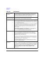
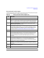
This guide applies to the signal generator models and associated serial number prefixes
listed below. Depending on your firmware revision, signal generator operation may vary
from descriptions in this guide.
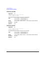
E8241A: US4124
E8244A: US4124
E8251A: US4124
E8254A: US4124
Part Number: E8251-90025
Printed in USA
February 2002
© Copyright 2001, 2002 Agilent Technologies Inc.
ii
Contents
1. Getting Started . . . . . . . . . . . . . . . . . . . . . . . . . . . . . . . . . . . . . . . . . . . . . . . . . . . 1
Introduction to Remote Operation . . . . . . . . . . . . . . . . . . . . . . . . . . . . . . . . . . . . . . . . . . 2
Interfaces. . . . . . . . . . . . . . . . . . . . . . . . . . . . . . . . . . . . . . . . . . . . . . . . . . . . . . . . . . . . . 3
IO Libraries. . . . . . . . . . . . . . . . . . . . . . . . . . . . . . . . . . . . . . . . . . . . . . . . . . . . . . . . . . . 3
Programming Language . . . . . . . . . . . . . . . . . . . . . . . . . . . . . . . . . . . . . . . . . . . . . . . . . 4
Using GPIB . . . . . . . . . . . . . . . . . . . . . . . . . . . . . . . . . . . . . . . . . . . . . . . . . . . . . . . . . . . . 5
1. Installing the GPIB Interface Card . . . . . . . . . . . . . . . . . . . . . . . . . . . . . . . . . . . . . . 5
2. Selecting IO Libraries for GPIB. . . . . . . . . . . . . . . . . . . . . . . . . . . . . . . . . . . . . . . . . 7
3. Setting Up the GPIB Interface. . . . . . . . . . . . . . . . . . . . . . . . . . . . . . . . . . . . . . . . . . 7
4. Verifying GPIB Functionality . . . . . . . . . . . . . . . . . . . . . . . . . . . . . . . . . . . . . . . . . . 8
GPIB Interface Terms. . . . . . . . . . . . . . . . . . . . . . . . . . . . . . . . . . . . . . . . . . . . . . . . . . . 8
GPIB Function Statements . . . . . . . . . . . . . . . . . . . . . . . . . . . . . . . . . . . . . . . . . . . . . . 9
Using LAN . . . . . . . . . . . . . . . . . . . . . . . . . . . . . . . . . . . . . . . . . . . . . . . . . . . . . . . . . . . . 14
1. Selecting IO Libraries for LAN . . . . . . . . . . . . . . . . . . . . . . . . . . . . . . . . . . . . . . . . 14
2. Setting Up the LAN Interface . . . . . . . . . . . . . . . . . . . . . . . . . . . . . . . . . . . . . . . . . 15
3. Verifying LAN Functionality . . . . . . . . . . . . . . . . . . . . . . . . . . . . . . . . . . . . . . . . . . 15
Using VXI-11 . . . . . . . . . . . . . . . . . . . . . . . . . . . . . . . . . . . . . . . . . . . . . . . . . . . . . . . . 17
Using Sockets LAN . . . . . . . . . . . . . . . . . . . . . . . . . . . . . . . . . . . . . . . . . . . . . . . . . . . 19
Using TELNET LAN . . . . . . . . . . . . . . . . . . . . . . . . . . . . . . . . . . . . . . . . . . . . . . . . . . 20
Using FTP . . . . . . . . . . . . . . . . . . . . . . . . . . . . . . . . . . . . . . . . . . . . . . . . . . . . . . . . . . 24
Using RS-232 . . . . . . . . . . . . . . . . . . . . . . . . . . . . . . . . . . . . . . . . . . . . . . . . . . . . . . . . . . 26
1. Selecting IO Libraries for RS-232 . . . . . . . . . . . . . . . . . . . . . . . . . . . . . . . . . . . . . . 26
2. Setting Up the RS-232 Interface . . . . . . . . . . . . . . . . . . . . . . . . . . . . . . . . . . . . . . . 27
3. Verifying RS-232 Functionality . . . . . . . . . . . . . . . . . . . . . . . . . . . . . . . . . . . . . . . . 28
Character Format Parameters . . . . . . . . . . . . . . . . . . . . . . . . . . . . . . . . . . . . . . . . . . . 29
2. Programming Examples. . . . . . . . . . . . . . . . . . . . . . . . . . . . . . . . . . . . . . . . . . . 31
Using the Programming Examples . . . . . . . . . . . . . . . . . . . . . . . . . . . . . . . . . . . . . . . .
Programming Examples Development Environment . . . . . . . . . . . . . . . . . . . . . . . . .
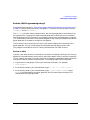
Running C/C++ Programming Examples . . . . . . . . . . . . . . . . . . . . . . . . . . . . . . . . . .
GPIB Programming Examples . . . . . . . . . . . . . . . . . . . . . . . . . . . . . . . . . . . . . . . . . . . .
Before Using the Examples . . . . . . . . . . . . . . . . . . . . . . . . . . . . . . . . . . . . . . . . . . . . .
Interface Check using Agilent BASIC . . . . . . . . . . . . . . . . . . . . . . . . . . . . . . . . . . . .
Interface Check Using NI-488.2 and C++ . . . . . . . . . . . . . . . . . . . . . . . . . . . . . . . . . .
Interface Check using VISA and C . . . . . . . . . . . . . . . . . . . . . . . . . . . . . . . . . . . . . . .
Local Lockout Using Agilent BASIC . . . . . . . . . . . . . . . . . . . . . . . . . . . . . . . . . . . . . .
Local Lockout Using NI-488.2 and C++ . . . . . . . . . . . . . . . . . . . . . . . . . . . . . . . . . . .
Queries Using Agilent BASIC . . . . . . . . . . . . . . . . . . . . . . . . . . . . . . . . . . . . . . . . . . .
32
33
33
34
34
35
36
37
38
39
41
iii
Contents
Queries Using NI-488.2 and C++. . . . . . . . . . . . . . . . . . . . . . . . . . . . . . . . . . . . . . . . .
Queries Using VISA and C. . . . . . . . . . . . . . . . . . . . . . . . . . . . . . . . . . . . . . . . . . . . . .
Generating a CW Signal Using VISA and C . . . . . . . . . . . . . . . . . . . . . . . . . . . . . . . .
Generating an Externally Applied AC-Coupled FM Signal Using VISA and C . . . .
Generating an Internal AC-Coupled FM Signal Using VISA and C . . . . . . . . . . . . .
Generating a Step-Swept Signal Using VISA and C . . . . . . . . . . . . . . . . . . . . . . . . .
Saving and Recalling States Using VISA and C . . . . . . . . . . . . . . . . . . . . . . . . . . . . .
Reading the Data Questionable Status Register Using VISA and C. . . . . . . . . . . . .
Reading the Service Request Interrupt (SRQ) Using VISA and C . . . . . . . . . . . . . .
LAN Programming Examples . . . . . . . . . . . . . . . . . . . . . . . . . . . . . . . . . . . . . . . . . . . . .
Before Using the Examples . . . . . . . . . . . . . . . . . . . . . . . . . . . . . . . . . . . . . . . . . . . . .
VXI-11 Programing . . . . . . . . . . . . . . . . . . . . . . . . . . . . . . . . . . . . . . . . . . . . . . . . . . .
Sockets LAN Programming using C . . . . . . . . . . . . . . . . . . . . . . . . . . . . . . . . . . . . . .
Sockets LAN Programming Using PERL . . . . . . . . . . . . . . . . . . . . . . . . . . . . . . . . . .
Sockets LAN Programming Using Java . . . . . . . . . . . . . . . . . . . . . . . . . . . . . . . . . . .
RS-232 Programming Examples . . . . . . . . . . . . . . . . . . . . . . . . . . . . . . . . . . . . . . . . . . .
Before Using the Examples . . . . . . . . . . . . . . . . . . . . . . . . . . . . . . . . . . . . . . . . . . . . .
Interface Check Using Agilent BASIC . . . . . . . . . . . . . . . . . . . . . . . . . . . . . . . . . . . .
Interface Check Using VISA and C . . . . . . . . . . . . . . . . . . . . . . . . . . . . . . . . . . . . . . .
Queries Using Agilent BASIC . . . . . . . . . . . . . . . . . . . . . . . . . . . . . . . . . . . . . . . . . . .
Queries Using VISA and C. . . . . . . . . . . . . . . . . . . . . . . . . . . . . . . . . . . . . . . . . . . . . .
43
45
47
49
51
53
55
57
60
64
64
65
69
89
91
93
93
94
95
97
98
3. Programming the Status Register System . . . . . . . . . . . . . . . . . . . . . . . . . . 101
Overview. . . . . . . . . . . . . . . . . . . . . . . . . . . . . . . . . . . . . . . . . . . . . . . . . . . . . . . . . . . . .
Status Register Bit Values. . . . . . . . . . . . . . . . . . . . . . . . . . . . . . . . . . . . . . . . . . . . . . .
Accessing Status Register Information. . . . . . . . . . . . . . . . . . . . . . . . . . . . . . . . . . . . .
Determining What to Monitor . . . . . . . . . . . . . . . . . . . . . . . . . . . . . . . . . . . . . . . . . .
Deciding How to Monitor . . . . . . . . . . . . . . . . . . . . . . . . . . . . . . . . . . . . . . . . . . . . . .
Status Register SCPI Commands . . . . . . . . . . . . . . . . . . . . . . . . . . . . . . . . . . . . . . .
Status Byte Group . . . . . . . . . . . . . . . . . . . . . . . . . . . . . . . . . . . . . . . . . . . . . . . . . . . . .
Status Byte Register. . . . . . . . . . . . . . . . . . . . . . . . . . . . . . . . . . . . . . . . . . . . . . . . . .
Service Request Enable Register . . . . . . . . . . . . . . . . . . . . . . . . . . . . . . . . . . . . . . . .
Status Groups. . . . . . . . . . . . . . . . . . . . . . . . . . . . . . . . . . . . . . . . . . . . . . . . . . . . . . . . .
Standard Event Status Group . . . . . . . . . . . . . . . . . . . . . . . . . . . . . . . . . . . . . . . . . .
Standard Operation Status Group. . . . . . . . . . . . . . . . . . . . . . . . . . . . . . . . . . . . . . .
Data Questionable Status Group . . . . . . . . . . . . . . . . . . . . . . . . . . . . . . . . . . . . . . . .
iv
102
104
105
105
106
108
110
111
112
113
114
117
120
Contents
Data Questionable Power Status Group . . . . . . . . . . . . . . . . . . . . . . . . . . . . . . . . . .
Data Questionable Frequency Status Group . . . . . . . . . . . . . . . . . . . . . . . . . . . . . .
Data Questionable Modulation Status Group. . . . . . . . . . . . . . . . . . . . . . . . . . . . . .
Data Questionable Calibration Status Group . . . . . . . . . . . . . . . . . . . . . . . . . . . . . .
124
127
130
133
4. Command Reference. . . . . . . . . . . . . . . . . . . . . . . . . . . . . . . . . . . . . . . . . . . . . 137
Command Reference Information . . . . . . . . . . . . . . . . . . . . . . . . . . . . . . . . . . . . . . . . .
SCPI Command Listings . . . . . . . . . . . . . . . . . . . . . . . . . . . . . . . . . . . . . . . . . . . . . .
Softkey and Hardkey Cross Reference . . . . . . . . . . . . . . . . . . . . . . . . . . . . . . . . . . .
Supported Signal Generator Series . . . . . . . . . . . . . . . . . . . . . . . . . . . . . . . . . . . . . .
SCPI Basics . . . . . . . . . . . . . . . . . . . . . . . . . . . . . . . . . . . . . . . . . . . . . . . . . . . . . . . . . .
Common Terms . . . . . . . . . . . . . . . . . . . . . . . . . . . . . . . . . . . . . . . . . . . . . . . . . . . . . .
Command Syntax . . . . . . . . . . . . . . . . . . . . . . . . . . . . . . . . . . . . . . . . . . . . . . . . . . . .
Command Types . . . . . . . . . . . . . . . . . . . . . . . . . . . . . . . . . . . . . . . . . . . . . . . . . . . .
Command Tree . . . . . . . . . . . . . . . . . . . . . . . . . . . . . . . . . . . . . . . . . . . . . . . . . . . . . .
Command Parameters and Responses . . . . . . . . . . . . . . . . . . . . . . . . . . . . . . . . . . .
Program Messages . . . . . . . . . . . . . . . . . . . . . . . . . . . . . . . . . . . . . . . . . . . . . . . . . . .
File Name Variables . . . . . . . . . . . . . . . . . . . . . . . . . . . . . . . . . . . . . . . . . . . . . . . . . .
MSUS (Mass Storage Unit Specifier) Variable . . . . . . . . . . . . . . . . . . . . . . . . . . . . .
Quote Usage with SCPI Commands . . . . . . . . . . . . . . . . . . . . . . . . . . . . . . . . . . . . .
Binary, Decimal, Hexadecimal, and Octal Formats . . . . . . . . . . . . . . . . . . . . . . . . .
IEEE 488.2 Common Commands . . . . . . . . . . . . . . . . . . . . . . . . . . . . . . . . . . . . . . . . .
*CLS . . . . . . . . . . . . . . . . . . . . . . . . . . . . . . . . . . . . . . . . . . . . . . . . . . . . . . . . . . . . . .
*ESE . . . . . . . . . . . . . . . . . . . . . . . . . . . . . . . . . . . . . . . . . . . . . . . . . . . . . . . . . . . . . .
*ESE?. . . . . . . . . . . . . . . . . . . . . . . . . . . . . . . . . . . . . . . . . . . . . . . . . . . . . . . . . . . . . .
*ESR?. . . . . . . . . . . . . . . . . . . . . . . . . . . . . . . . . . . . . . . . . . . . . . . . . . . . . . . . . . . . . .
*IDN?. . . . . . . . . . . . . . . . . . . . . . . . . . . . . . . . . . . . . . . . . . . . . . . . . . . . . . . . . . . . . .
*OPC . . . . . . . . . . . . . . . . . . . . . . . . . . . . . . . . . . . . . . . . . . . . . . . . . . . . . . . . . . . . . .
*OPC? . . . . . . . . . . . . . . . . . . . . . . . . . . . . . . . . . . . . . . . . . . . . . . . . . . . . . . . . . . . . .
*PSC . . . . . . . . . . . . . . . . . . . . . . . . . . . . . . . . . . . . . . . . . . . . . . . . . . . . . . . . . . . . . .
*PSC?. . . . . . . . . . . . . . . . . . . . . . . . . . . . . . . . . . . . . . . . . . . . . . . . . . . . . . . . . . . . . .
*RCL . . . . . . . . . . . . . . . . . . . . . . . . . . . . . . . . . . . . . . . . . . . . . . . . . . . . . . . . . . . . . .
*RST . . . . . . . . . . . . . . . . . . . . . . . . . . . . . . . . . . . . . . . . . . . . . . . . . . . . . . . . . . . . . .
*SAV . . . . . . . . . . . . . . . . . . . . . . . . . . . . . . . . . . . . . . . . . . . . . . . . . . . . . . . . . . . . . .
*SRE . . . . . . . . . . . . . . . . . . . . . . . . . . . . . . . . . . . . . . . . . . . . . . . . . . . . . . . . . . . . . .
*SRE?. . . . . . . . . . . . . . . . . . . . . . . . . . . . . . . . . . . . . . . . . . . . . . . . . . . . . . . . . . . . . .
*STB?. . . . . . . . . . . . . . . . . . . . . . . . . . . . . . . . . . . . . . . . . . . . . . . . . . . . . . . . . . . . . .
*TRG . . . . . . . . . . . . . . . . . . . . . . . . . . . . . . . . . . . . . . . . . . . . . . . . . . . . . . . . . . . . . .
138
138
138
138
139
139
140
142
143
144
149
150
151
152
153
154
154
154
155
155
156
156
157
157
158
158
158
159
159
160
160
160
v
Contents
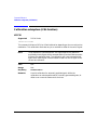
*TST? . . . . . . . . . . . . . . . . . . . . . . . . . . . . . . . . . . . . . . . . . . . . . . . . . . . . . . . . . . . . . .
*WAI . . . . . . . . . . . . . . . . . . . . . . . . . . . . . . . . . . . . . . . . . . . . . . . . . . . . . . . . . . . . . .
Calibration subsystem (:CALibration) . . . . . . . . . . . . . . . . . . . . . . . . . . . . . . . . . . . . .
:DCFM . . . . . . . . . . . . . . . . . . . . . . . . . . . . . . . . . . . . . . . . . . . . . . . . . . . . . . . . . . . . .
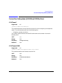
Communication Subsystem (:SYSTem:COMMunicate). . . . . . . . . . . . . . . . . . . . . . . .
:GPIB:ADDRess . . . . . . . . . . . . . . . . . . . . . . . . . . . . . . . . . . . . . . . . . . . . . . . . . . . . .
:LAN:HOSTname . . . . . . . . . . . . . . . . . . . . . . . . . . . . . . . . . . . . . . . . . . . . . . . . . . . .
:LAN:IP . . . . . . . . . . . . . . . . . . . . . . . . . . . . . . . . . . . . . . . . . . . . . . . . . . . . . . . . . . . .
:PMETer:ADDRess . . . . . . . . . . . . . . . . . . . . . . . . . . . . . . . . . . . . . . . . . . . . . . . . . . .
:PMETer:CHANnel . . . . . . . . . . . . . . . . . . . . . . . . . . . . . . . . . . . . . . . . . . . . . . . . . .
:PMETer:IDN . . . . . . . . . . . . . . . . . . . . . . . . . . . . . . . . . . . . . . . . . . . . . . . . . . . . . . .
:PMETer:TIMEout . . . . . . . . . . . . . . . . . . . . . . . . . . . . . . . . . . . . . . . . . . . . . . . . . . .
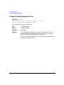
:SERial:BAUD . . . . . . . . . . . . . . . . . . . . . . . . . . . . . . . . . . . . . . . . . . . . . . . . . . . . . . .
:SERial:ECHO. . . . . . . . . . . . . . . . . . . . . . . . . . . . . . . . . . . . . . . . . . . . . . . . . . . . . . .
:SERial:RECeive:PACE . . . . . . . . . . . . . . . . . . . . . . . . . . . . . . . . . . . . . . . . . . . . . . .
:SERial:RESet . . . . . . . . . . . . . . . . . . . . . . . . . . . . . . . . . . . . . . . . . . . . . . . . . . . . . . .
:SERial:TOUT . . . . . . . . . . . . . . . . . . . . . . . . . . . . . . . . . . . . . . . . . . . . . . . . . . . . . . .
:SERial:TRANsmit:PACE. . . . . . . . . . . . . . . . . . . . . . . . . . . . . . . . . . . . . . . . . . . . . .
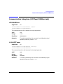
Diagnostic Subsystem (:DIAGnostic) . . . . . . . . . . . . . . . . . . . . . . . . . . . . . . . . . . . . . .
[:CPU]:INFOrmation:BOARds. . . . . . . . . . . . . . . . . . . . . . . . . . . . . . . . . . . . . . . . . .
[:CPU]:INFOrmation:CCOunt:ATTenuator . . . . . . . . . . . . . . . . . . . . . . . . . . . . . . .
[:CPU]:INFOrmation:CCOunt:PON . . . . . . . . . . . . . . . . . . . . . . . . . . . . . . . . . . . . .
[:CPU]:INFOrmation:DISPlay:OTIMe . . . . . . . . . . . . . . . . . . . . . . . . . . . . . . . . . . .
[:CPU]:INFOrmation:OPTions. . . . . . . . . . . . . . . . . . . . . . . . . . . . . . . . . . . . . . . . . .
[:CPU]:INFOrmation:OPTions:DETail . . . . . . . . . . . . . . . . . . . . . . . . . . . . . . . . . . .
[:CPU]:INFOrmation:OTIMe . . . . . . . . . . . . . . . . . . . . . . . . . . . . . . . . . . . . . . . . . . .
[:CPU]:INFOrmation:REVision . . . . . . . . . . . . . . . . . . . . . . . . . . . . . . . . . . . . . . . . .
[:CPU]:INFOrmation:SDATe . . . . . . . . . . . . . . . . . . . . . . . . . . . . . . . . . . . . . . . . . . .
Display Subsystem (:DISPlay) . . . . . . . . . . . . . . . . . . . . . . . . . . . . . . . . . . . . . . . . . . .
:BRIGhtness . . . . . . . . . . . . . . . . . . . . . . . . . . . . . . . . . . . . . . . . . . . . . . . . . . . . . . . .
:CAPture . . . . . . . . . . . . . . . . . . . . . . . . . . . . . . . . . . . . . . . . . . . . . . . . . . . . . . . . . . .
:CONTrast . . . . . . . . . . . . . . . . . . . . . . . . . . . . . . . . . . . . . . . . . . . . . . . . . . . . . . . . . .
:INVerse. . . . . . . . . . . . . . . . . . . . . . . . . . . . . . . . . . . . . . . . . . . . . . . . . . . . . . . . . . . .
:REMote. . . . . . . . . . . . . . . . . . . . . . . . . . . . . . . . . . . . . . . . . . . . . . . . . . . . . . . . . . . .
[:WINDow][:STATe] . . . . . . . . . . . . . . . . . . . . . . . . . . . . . . . . . . . . . . . . . . . . . . . . . .
Memory Subsystem (:MEMory). . . . . . . . . . . . . . . . . . . . . . . . . . . . . . . . . . . . . . . . . . .
vi
161
161
162
162
163
163
163
164
164
165
165
166
166
167
167
168
168
169
170
170
170
171
171
171
172
172
172
173
174
174
174
175
175
176
176
177
Contents
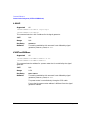
:CATalog:BINary. . . . . . . . . . . . . . . . . . . . . . . . . . . . . . . . . . . . . . . . . . . . . . . . . . . . .
:CATalog:LIST. . . . . . . . . . . . . . . . . . . . . . . . . . . . . . . . . . . . . . . . . . . . . . . . . . . . . . .
:CATalog:STATe . . . . . . . . . . . . . . . . . . . . . . . . . . . . . . . . . . . . . . . . . . . . . . . . . . . . .
:CATalog:UFLT . . . . . . . . . . . . . . . . . . . . . . . . . . . . . . . . . . . . . . . . . . . . . . . . . . . . . .
:CATalog[:ALL] . . . . . . . . . . . . . . . . . . . . . . . . . . . . . . . . . . . . . . . . . . . . . . . . . . . . . .
:COPY[:NAME] . . . . . . . . . . . . . . . . . . . . . . . . . . . . . . . . . . . . . . . . . . . . . . . . . . . . . .
:DATA . . . . . . . . . . . . . . . . . . . . . . . . . . . . . . . . . . . . . . . . . . . . . . . . . . . . . . . . . . . . .
:DELete:ALL . . . . . . . . . . . . . . . . . . . . . . . . . . . . . . . . . . . . . . . . . . . . . . . . . . . . . . . .
:DELete:BINary . . . . . . . . . . . . . . . . . . . . . . . . . . . . . . . . . . . . . . . . . . . . . . . . . . . . .
:DELete:LIST . . . . . . . . . . . . . . . . . . . . . . . . . . . . . . . . . . . . . . . . . . . . . . . . . . . . . . .
:DELete:STATe . . . . . . . . . . . . . . . . . . . . . . . . . . . . . . . . . . . . . . . . . . . . . . . . . . . . . .
:DELete:UFLT. . . . . . . . . . . . . . . . . . . . . . . . . . . . . . . . . . . . . . . . . . . . . . . . . . . . . . .
:DELete[:NAME]. . . . . . . . . . . . . . . . . . . . . . . . . . . . . . . . . . . . . . . . . . . . . . . . . . . . .
:FREE[:ALL] . . . . . . . . . . . . . . . . . . . . . . . . . . . . . . . . . . . . . . . . . . . . . . . . . . . . . . . .
:LOAD:LIST . . . . . . . . . . . . . . . . . . . . . . . . . . . . . . . . . . . . . . . . . . . . . . . . . . . . . . . .
:MOVE . . . . . . . . . . . . . . . . . . . . . . . . . . . . . . . . . . . . . . . . . . . . . . . . . . . . . . . . . . . . .
:STATe:COMMent. . . . . . . . . . . . . . . . . . . . . . . . . . . . . . . . . . . . . . . . . . . . . . . . . . . .
:STORe:LIST . . . . . . . . . . . . . . . . . . . . . . . . . . . . . . . . . . . . . . . . . . . . . . . . . . . . . . . .
Mass Memory Subsystem (:MMEMory) . . . . . . . . . . . . . . . . . . . . . . . . . . . . . . . . . . . .
:CATalog . . . . . . . . . . . . . . . . . . . . . . . . . . . . . . . . . . . . . . . . . . . . . . . . . . . . . . . . . . .
:COPY . . . . . . . . . . . . . . . . . . . . . . . . . . . . . . . . . . . . . . . . . . . . . . . . . . . . . . . . . . . . .
:DATA . . . . . . . . . . . . . . . . . . . . . . . . . . . . . . . . . . . . . . . . . . . . . . . . . . . . . . . . . . . . .
:DELete[:NAME]. . . . . . . . . . . . . . . . . . . . . . . . . . . . . . . . . . . . . . . . . . . . . . . . . . . . .
:LOAD:LIST . . . . . . . . . . . . . . . . . . . . . . . . . . . . . . . . . . . . . . . . . . . . . . . . . . . . . . . .
:MOVE . . . . . . . . . . . . . . . . . . . . . . . . . . . . . . . . . . . . . . . . . . . . . . . . . . . . . . . . . . . . .
:STORe:LIST . . . . . . . . . . . . . . . . . . . . . . . . . . . . . . . . . . . . . . . . . . . . . . . . . . . . . . .
Output Subsystem(:OUTPut) . . . . . . . . . . . . . . . . . . . . . . . . . . . . . . . . . . . . . . . . . . . .
:MODulation[:STATe] . . . . . . . . . . . . . . . . . . . . . . . . . . . . . . . . . . . . . . . . . . . . . . . .
[:STATe]. . . . . . . . . . . . . . . . . . . . . . . . . . . . . . . . . . . . . . . . . . . . . . . . . . . . . . . . . . . .
Status Subsystem (:STATus). . . . . . . . . . . . . . . . . . . . . . . . . . . . . . . . . . . . . . . . . . . . .
:OPERation:CONDition . . . . . . . . . . . . . . . . . . . . . . . . . . . . . . . . . . . . . . . . . . . . . . .
:OPERation:ENABle. . . . . . . . . . . . . . . . . . . . . . . . . . . . . . . . . . . . . . . . . . . . . . . . . .
:OPERation:NTRansition . . . . . . . . . . . . . . . . . . . . . . . . . . . . . . . . . . . . . . . . . . . . . .
:OPERation:PTRansition . . . . . . . . . . . . . . . . . . . . . . . . . . . . . . . . . . . . . . . . . . . . . .
:OPERation[:EVENt] . . . . . . . . . . . . . . . . . . . . . . . . . . . . . . . . . . . . . . . . . . . . . . . . .
:PRESet . . . . . . . . . . . . . . . . . . . . . . . . . . . . . . . . . . . . . . . . . . . . . . . . . . . . . . . . . . . .
:QUEStionable:CALibration:CONDition. . . . . . . . . . . . . . . . . . . . . . . . . . . . . . . . . .
:QUEStionable:CALibration:ENABle . . . . . . . . . . . . . . . . . . . . . . . . . . . . . . . . . . . .
177
178
178
179
179
180
180
181
181
182
182
182
183
183
183
184
184
184
185
185
186
186
187
187
188
188
189
189
189
190
190
190
191
191
192
192
193
193
vii
Contents
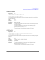
:QUEStionable:CALibration:NTRansition . . . . . . . . . . . . . . . . . . . . . . . . . . . . . . . .
:QUEStionable:CALibration:PTRansition. . . . . . . . . . . . . . . . . . . . . . . . . . . . . . . . .
:QUEStionable:CALibration[:EVENt] . . . . . . . . . . . . . . . . . . . . . . . . . . . . . . . . . . . .
:QUEStionable:CONDition. . . . . . . . . . . . . . . . . . . . . . . . . . . . . . . . . . . . . . . . . . . . .
:QUEStionable:ENABle . . . . . . . . . . . . . . . . . . . . . . . . . . . . . . . . . . . . . . . . . . . . . . .
:QUEStionable:FREQuency:CONDition . . . . . . . . . . . . . . . . . . . . . . . . . . . . . . . . . .
:QUEStionable:FREQuency:ENABle. . . . . . . . . . . . . . . . . . . . . . . . . . . . . . . . . . . . .
:QUEStionable:FREQuency:NTRansition. . . . . . . . . . . . . . . . . . . . . . . . . . . . . . . . .
:QUEStionable:FREQuency:PTRansition . . . . . . . . . . . . . . . . . . . . . . . . . . . . . . . . .
:QUEStionable:FREQuency[:EVENt] . . . . . . . . . . . . . . . . . . . . . . . . . . . . . . . . . . . .
:QUEStionable:MODulation:CONDition. . . . . . . . . . . . . . . . . . . . . . . . . . . . . . . . . .
:QUEStionable:MODulation:ENABle . . . . . . . . . . . . . . . . . . . . . . . . . . . . . . . . . . . .
:QUEStionable:MODulation:NTRansition . . . . . . . . . . . . . . . . . . . . . . . . . . . . . . . .
:QUEStionable:MODulation:PTRansition. . . . . . . . . . . . . . . . . . . . . . . . . . . . . . . . .
:QUEStionable:MODulation[:EVENt] . . . . . . . . . . . . . . . . . . . . . . . . . . . . . . . . . . . .
:QUEStionable:NTRansition . . . . . . . . . . . . . . . . . . . . . . . . . . . . . . . . . . . . . . . . . . .
:QUEStionable:POWer:CONDition . . . . . . . . . . . . . . . . . . . . . . . . . . . . . . . . . . . . . .
:QUEStionable:POWer:ENABle. . . . . . . . . . . . . . . . . . . . . . . . . . . . . . . . . . . . . . . . .
:QUEStionable:POWer:NTRansition . . . . . . . . . . . . . . . . . . . . . . . . . . . . . . . . . . . . .
:QUEStionable:POWer:PTRansition . . . . . . . . . . . . . . . . . . . . . . . . . . . . . . . . . . . . .
:QUEStionable:POWer[:EVENt] . . . . . . . . . . . . . . . . . . . . . . . . . . . . . . . . . . . . . . . .
:QUEStionable:PTRansition . . . . . . . . . . . . . . . . . . . . . . . . . . . . . . . . . . . . . . . . . . .
:QUEStionable[:EVENt]. . . . . . . . . . . . . . . . . . . . . . . . . . . . . . . . . . . . . . . . . . . . . . .
System Subsystem (:SYSTem). . . . . . . . . . . . . . . . . . . . . . . . . . . . . . . . . . . . . . . . . . . .
:CAPability . . . . . . . . . . . . . . . . . . . . . . . . . . . . . . . . . . . . . . . . . . . . . . . . . . . . . . . . .
:ERRor[:NEXT] . . . . . . . . . . . . . . . . . . . . . . . . . . . . . . . . . . . . . . . . . . . . . . . . . . . . . .
:HELP:MODE . . . . . . . . . . . . . . . . . . . . . . . . . . . . . . . . . . . . . . . . . . . . . . . . . . . . . . .
:PON:TYPE . . . . . . . . . . . . . . . . . . . . . . . . . . . . . . . . . . . . . . . . . . . . . . . . . . . . . . . . .
:PRESet . . . . . . . . . . . . . . . . . . . . . . . . . . . . . . . . . . . . . . . . . . . . . . . . . . . . . . . . . . . .
:PRESet:ALL . . . . . . . . . . . . . . . . . . . . . . . . . . . . . . . . . . . . . . . . . . . . . . . . . . . . . . . .
:PRESet:PERSistent. . . . . . . . . . . . . . . . . . . . . . . . . . . . . . . . . . . . . . . . . . . . . . . . . .
:PRESet:TYPE . . . . . . . . . . . . . . . . . . . . . . . . . . . . . . . . . . . . . . . . . . . . . . . . . . . . . .
:PRESet[:USER]:SAVE. . . . . . . . . . . . . . . . . . . . . . . . . . . . . . . . . . . . . . . . . . . . . . . .
:SSAVer:DELay . . . . . . . . . . . . . . . . . . . . . . . . . . . . . . . . . . . . . . . . . . . . . . . . . . . . . .
:SSAVer:MODE . . . . . . . . . . . . . . . . . . . . . . . . . . . . . . . . . . . . . . . . . . . . . . . . . . . . . .
:SSAVer:STATe . . . . . . . . . . . . . . . . . . . . . . . . . . . . . . . . . . . . . . . . . . . . . . . . . . . . . .
viii
194
194
195
195
196
196
197
197
198
199
199
200
200
201
202
203
203
204
204
205
206
207
207
208
208
208
209
210
210
211
211
212
212
213
213
214
Contents
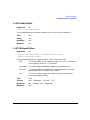
:VERSion . . . . . . . . . . . . . . . . . . . . . . . . . . . . . . . . . . . . . . . . . . . . . . . . . . . . . . . . . . .
Trigger Subsystem . . . . . . . . . . . . . . . . . . . . . . . . . . . . . . . . . . . . . . . . . . . . . . . . . . . . .
:ABORt . . . . . . . . . . . . . . . . . . . . . . . . . . . . . . . . . . . . . . . . . . . . . . . . . . . . . . . . . . . .
:INITiate:CONTinuous[:ALL] . . . . . . . . . . . . . . . . . . . . . . . . . . . . . . . . . . . . . . . . . .
:INITiate[:IMMediate][:ALL] . . . . . . . . . . . . . . . . . . . . . . . . . . . . . . . . . . . . . . . . . . .
:TRIGger:OUTPut:POLarity . . . . . . . . . . . . . . . . . . . . . . . . . . . . . . . . . . . . . . . . . . .
:TRIGger[:SEQuence]:SLOPe. . . . . . . . . . . . . . . . . . . . . . . . . . . . . . . . . . . . . . . . . . .
:TRIGger[:SEQuence]:SOURce . . . . . . . . . . . . . . . . . . . . . . . . . . . . . . . . . . . . . . . . .
:TRIGger[:SEQuence][:IMMediate] . . . . . . . . . . . . . . . . . . . . . . . . . . . . . . . . . . . . . .
Unit Subsystem (:UNIT) . . . . . . . . . . . . . . . . . . . . . . . . . . . . . . . . . . . . . . . . . . . . . . . .
:POWer . . . . . . . . . . . . . . . . . . . . . . . . . . . . . . . . . . . . . . . . . . . . . . . . . . . . . . . . . . . .
Amplitude Modulation Subsystem ([:SOURce]) . . . . . . . . . . . . . . . . . . . . . . . . . . . . . .
:AM[1]|2.... . . . . . . . . . . . . . . . . . . . . . . . . . . . . . . . . . . . . . . . . . . . . . . . . . . . . . . . . .
:AM:INTernal:FREQuency:STEP[:INCRement] . . . . . . . . . . . . . . . . . . . . . . . . . . . .
:AM:MODE . . . . . . . . . . . . . . . . . . . . . . . . . . . . . . . . . . . . . . . . . . . . . . . . . . . . . . . . .
:AM[1]|2:EXTernal[1]|2:COUPling . . . . . . . . . . . . . . . . . . . . . . . . . . . . . . . . . . . . .
:AM[1]|2:EXTernal[1]|2:IMPedance. . . . . . . . . . . . . . . . . . . . . . . . . . . . . . . . . . . . .
:AM[1]|2:INTernal[1]:FREQuency:ALTernate . . . . . . . . . . . . . . . . . . . . . . . . . . . . .
:AM[1]|2:INTernal[1]:FREQuency:ALTernate:AMPLitude:PERCent . . . . . . . . . .
:AM[1]|2:INTernal[1]:SWEep:RATE. . . . . . . . . . . . . . . . . . . . . . . . . . . . . . . . . . . . .
:AM[1]|2:INTernal[1]:SWEep:TRIGger . . . . . . . . . . . . . . . . . . . . . . . . . . . . . . . . . .
:AM[1]|2:INTernal[1]|2:FREQuency . . . . . . . . . . . . . . . . . . . . . . . . . . . . . . . . . . . .
:AM[1]|2:INTernal[1]|2:FUNCtion:NOISe . . . . . . . . . . . . . . . . . . . . . . . . . . . . . . .
:AM[1]|2:INTernal[1]|2:FUNCtion:RAMP. . . . . . . . . . . . . . . . . . . . . . . . . . . . . . . .
:AM[1]|2:INTernal[1]|2:FUNCtion:SHAPe . . . . . . . . . . . . . . . . . . . . . . . . . . . . . . .
:AM[1]|2:SOURce. . . . . . . . . . . . . . . . . . . . . . . . . . . . . . . . . . . . . . . . . . . . . . . . . . . .
:AM[1]|2:STATe . . . . . . . . . . . . . . . . . . . . . . . . . . . . . . . . . . . . . . . . . . . . . . . . . . . . .
:AM[1]|2:TYPE. . . . . . . . . . . . . . . . . . . . . . . . . . . . . . . . . . . . . . . . . . . . . . . . . . . . . .
:AM[1]|2[:DEPTh]:EXPonential . . . . . . . . . . . . . . . . . . . . . . . . . . . . . . . . . . . . . . . .
:AM[1]|2[:DEPTh][:LINear] . . . . . . . . . . . . . . . . . . . . . . . . . . . . . . . . . . . . . . . . . . .
:AM[1]|2[:DEPTh][:LINear]:TRACk . . . . . . . . . . . . . . . . . . . . . . . . . . . . . . . . . . . . .
:AM[:DEPTh]:STEP[:INCRement]. . . . . . . . . . . . . . . . . . . . . . . . . . . . . . . . . . . . . . .
Correction Subsystem ([:SOURce]:CORRection) . . . . . . . . . . . . . . . . . . . . . . . . . . . . .
:FLATness? . . . . . . . . . . . . . . . . . . . . . . . . . . . . . . . . . . . . . . . . . . . . . . . . . . . . . . . . .
:FLATness:LOAD . . . . . . . . . . . . . . . . . . . . . . . . . . . . . . . . . . . . . . . . . . . . . . . . . . . .
:FLATness:PAIR . . . . . . . . . . . . . . . . . . . . . . . . . . . . . . . . . . . . . . . . . . . . . . . . . . . . .
:FLATness:POINts? . . . . . . . . . . . . . . . . . . . . . . . . . . . . . . . . . . . . . . . . . . . . . . . . . .
:FLATness:PRESet . . . . . . . . . . . . . . . . . . . . . . . . . . . . . . . . . . . . . . . . . . . . . . . . . . .
214
215
215
215
216
216
217
217
218
219
219
220
220
221
222
223
223
224
224
225
225
226
226
227
227
228
228
229
229
230
231
232
233
233
233
234
234
235
ix
Contents
:FLATness:STORe . . . . . . . . . . . . . . . . . . . . . . . . . . . . . . . . . . . . . . . . . . . . . . . . . . .
[:STATe] . . . . . . . . . . . . . . . . . . . . . . . . . . . . . . . . . . . . . . . . . . . . . . . . . . . . . . . . . . .
Frequency Subsystem ([:SOURce]) . . . . . . . . . . . . . . . . . . . . . . . . . . . . . . . . . . . . . . . .
:FREQuency:FIXed . . . . . . . . . . . . . . . . . . . . . . . . . . . . . . . . . . . . . . . . . . . . . . . . . . .
:FREQuency:MODE . . . . . . . . . . . . . . . . . . . . . . . . . . . . . . . . . . . . . . . . . . . . . . . . . .
:FREQuency:MULTiplier . . . . . . . . . . . . . . . . . . . . . . . . . . . . . . . . . . . . . . . . . . . . . .
:FREQuency:OFFSet . . . . . . . . . . . . . . . . . . . . . . . . . . . . . . . . . . . . . . . . . . . . . . . . .
:FREQuency:OFFSet:STATe . . . . . . . . . . . . . . . . . . . . . . . . . . . . . . . . . . . . . . . . . . .
:FREQuency:REFerence . . . . . . . . . . . . . . . . . . . . . . . . . . . . . . . . . . . . . . . . . . . . . .
:FREQuency:REFerence:STATe . . . . . . . . . . . . . . . . . . . . . . . . . . . . . . . . . . . . . . . .
:FREQuency:STARt . . . . . . . . . . . . . . . . . . . . . . . . . . . . . . . . . . . . . . . . . . . . . . . . . .
:FREQuency:STOP . . . . . . . . . . . . . . . . . . . . . . . . . . . . . . . . . . . . . . . . . . . . . . . . . .
:FREQuency[:CW] . . . . . . . . . . . . . . . . . . . . . . . . . . . . . . . . . . . . . . . . . . . . . . . . . . .
:PHASe:REFerence . . . . . . . . . . . . . . . . . . . . . . . . . . . . . . . . . . . . . . . . . . . . . . . . . . .
:PHASe[:ADJust] . . . . . . . . . . . . . . . . . . . . . . . . . . . . . . . . . . . . . . . . . . . . . . . . . . . .
:ROSCillator:SOURce . . . . . . . . . . . . . . . . . . . . . . . . . . . . . . . . . . . . . . . . . . . . . . . . .
:ROSCillator:SOURce:AUTO . . . . . . . . . . . . . . . . . . . . . . . . . . . . . . . . . . . . . . . . . .
Frequency Modulation Subsystem ([:SOURce]) . . . . . . . . . . . . . . . . . . . . . . . . . . . . . .
:FM[1]|2... . . . . . . . . . . . . . . . . . . . . . . . . . . . . . . . . . . . . . . . . . . . . . . . . . . . . . . . . . .
:FM:INTernal:FREQuency:STEP[:INCRement] . . . . . . . . . . . . . . . . . . . . . . . . . . . .
:FM[1]|2:EXTernal[1]|2:COUPLing . . . . . . . . . . . . . . . . . . . . . . . . . . . . . . . . . . . .
:FM[1]|2:EXTernal[1]|2:IMPedance. . . . . . . . . . . . . . . . . . . . . . . . . . . . . . . . . . . . .
:FM[1]|2:INTernal[1]:FREQuency:ALTernate . . . . . . . . . . . . . . . . . . . . . . . . . . . .
:FM[1]|2:INTernal[1]:FREQuency:ALTernate:AMPLitude:PERCent . . . . . . . . . .
:FM[1]|2:INTernal[1]:SWEep:RATE. . . . . . . . . . . . . . . . . . . . . . . . . . . . . . . . . . . . .
:FM[1]|2:INTernal[1]:SWEep:TRIGger . . . . . . . . . . . . . . . . . . . . . . . . . . . . . . . . . .
:FM[1]|2:INTernal[1]|2:FREQuency . . . . . . . . . . . . . . . . . . . . . . . . . . . . . . . . . . . .
:FM[1]|2:INTernal[1]|2:FUNCtion:NOISe . . . . . . . . . . . . . . . . . . . . . . . . . . . . . . .
:FM[1]|2:INTernal[1]|2:FUNCtion:RAMP. . . . . . . . . . . . . . . . . . . . . . . . . . . . . . . .
:FM[1]|2:INTernal[1]|2:FUNCtion:SHAPe . . . . . . . . . . . . . . . . . . . . . . . . . . . . . . .
:FM[1]|2:SOURce . . . . . . . . . . . . . . . . . . . . . . . . . . . . . . . . . . . . . . . . . . . . . . . . . . . .
:FM[1]|2:STATe . . . . . . . . . . . . . . . . . . . . . . . . . . . . . . . . . . . . . . . . . . . . . . . . . . . . .
:FM[1]|2[:DEViation] . . . . . . . . . . . . . . . . . . . . . . . . . . . . . . . . . . . . . . . . . . . . . . . . .
:FM[1]|2[:DEViation]:TRACk . . . . . . . . . . . . . . . . . . . . . . . . . . . . . . . . . . . . . . . . . .
List/Sweep subsystem ([:SOURce]) . . . . . . . . . . . . . . . . . . . . . . . . . . . . . . . . . . . . . . . .
:LIST:DIRection . . . . . . . . . . . . . . . . . . . . . . . . . . . . . . . . . . . . . . . . . . . . . . . . . . . . .
x
235
236
237
237
237
238
238
239
239
239
240
240
241
241
242
242
243
244
244
245
245
246
246
247
247
248
249
249
250
250
251
251
252
253
254
254
Contents
:LIST:DWELl. . . . . . . . . . . . . . . . . . . . . . . . . . . . . . . . . . . . . . . . . . . . . . . . . . . . . . . .
:LIST:DWELl:POINts . . . . . . . . . . . . . . . . . . . . . . . . . . . . . . . . . . . . . . . . . . . . . . . . .
:LIST:DWELl:TYPE . . . . . . . . . . . . . . . . . . . . . . . . . . . . . . . . . . . . . . . . . . . . . . . . . .
:LIST:FREQuency . . . . . . . . . . . . . . . . . . . . . . . . . . . . . . . . . . . . . . . . . . . . . . . . . . . .
:LIST:FREQuency:POINts . . . . . . . . . . . . . . . . . . . . . . . . . . . . . . . . . . . . . . . . . . . . .
:LIST:MANual. . . . . . . . . . . . . . . . . . . . . . . . . . . . . . . . . . . . . . . . . . . . . . . . . . . . . . .
:LIST:MODE . . . . . . . . . . . . . . . . . . . . . . . . . . . . . . . . . . . . . . . . . . . . . . . . . . . . . . . .
:LIST:POWer . . . . . . . . . . . . . . . . . . . . . . . . . . . . . . . . . . . . . . . . . . . . . . . . . . . . . . . .
:LIST:POWer:POINts . . . . . . . . . . . . . . . . . . . . . . . . . . . . . . . . . . . . . . . . . . . . . . . . .
:LIST:TRIGger:SOURce . . . . . . . . . . . . . . . . . . . . . . . . . . . . . . . . . . . . . . . . . . . . . . .
:LIST:TYPE . . . . . . . . . . . . . . . . . . . . . . . . . . . . . . . . . . . . . . . . . . . . . . . . . . . . . . . . .
:LIST:TYPE:LIST:INITialize:FSTep . . . . . . . . . . . . . . . . . . . . . . . . . . . . . . . . . . . . .
:LIST:TYPE:LIST:INITialize:PRESet . . . . . . . . . . . . . . . . . . . . . . . . . . . . . . . . . . . .
:SWEep:DWELl. . . . . . . . . . . . . . . . . . . . . . . . . . . . . . . . . . . . . . . . . . . . . . . . . . . . . .
:SWEep:POINts . . . . . . . . . . . . . . . . . . . . . . . . . . . . . . . . . . . . . . . . . . . . . . . . . . . . .
Low Frequency Output Subsystem ([:SOURce]:LFOutput) . . . . . . . . . . . . . . . . . . . .
:AMPLitude . . . . . . . . . . . . . . . . . . . . . . . . . . . . . . . . . . . . . . . . . . . . . . . . . . . . . . . . .
:FUNCtion[1]:FREQuency:ALTernate . . . . . . . . . . . . . . . . . . . . . . . . . . . . . . . . . . .
:FUNCtion[1]:FREQuency:ALTernate:AMPLitude:PERCent . . . . . . . . . . . . . . . . .
:FUNCtion[1]:SWEep:RATE . . . . . . . . . . . . . . . . . . . . . . . . . . . . . . . . . . . . . . . . . . .
:FUNCtion[1]:SWEep:TRIGger . . . . . . . . . . . . . . . . . . . . . . . . . . . . . . . . . . . . . . . . .
:FUNCtion[1]|2:FREQuency . . . . . . . . . . . . . . . . . . . . . . . . . . . . . . . . . . . . . . . . . . .
:FUNCtion[1]|2:SHAPe . . . . . . . . . . . . . . . . . . . . . . . . . . . . . . . . . . . . . . . . . . . . . .
:FUNCtion:NOISe. . . . . . . . . . . . . . . . . . . . . . . . . . . . . . . . . . . . . . . . . . . . . . . . . . . .
:FUNCtion[1]|2:SHAPe:RAMP . . . . . . . . . . . . . . . . . . . . . . . . . . . . . . . . . . . . . . . . .
:SOURce . . . . . . . . . . . . . . . . . . . . . . . . . . . . . . . . . . . . . . . . . . . . . . . . . . . . . . . . . . .
:STATe . . . . . . . . . . . . . . . . . . . . . . . . . . . . . . . . . . . . . . . . . . . . . . . . . . . . . . . . . . . . .
Phase Modulation subsystem ([:SOURce]) . . . . . . . . . . . . . . . . . . . . . . . . . . . . . . . . . .
:PM[1]|2... . . . . . . . . . . . . . . . . . . . . . . . . . . . . . . . . . . . . . . . . . . . . . . . . . . . . . . . . . .
:PM:INTernal:FREQuency:STEP[:INCRement] . . . . . . . . . . . . . . . . . . . . . . . . . . . .
:PM[1]|2:BANDwidth|BWIDth . . . . . . . . . . . . . . . . . . . . . . . . . . . . . . . . . . . . . . . .
:PM[1]|2:EXTernal[1]|2:COUPling . . . . . . . . . . . . . . . . . . . . . . . . . . . . . . . . . . . . .
:PM[1]|2:EXTernal[1]|2:IMPedance. . . . . . . . . . . . . . . . . . . . . . . . . . . . . . . . . . . . .
:PM[1]|2:INTernal[1]:FREQuency:ALTernate . . . . . . . . . . . . . . . . . . . . . . . . . . . . .
:PM[1]|2:INTernal[1]:FREQuency:ALTernate:AMPLitude:PERCent . . . . . . . . . .
:PM[1]|2:INTernal[1]:SWEep:RATE. . . . . . . . . . . . . . . . . . . . . . . . . . . . . . . . . . . . .
:PM[1]|2:INTernal[1]:SWEep:TRIGger . . . . . . . . . . . . . . . . . . . . . . . . . . . . . . . . . .
:PM[1]|2:INTernal[1]|2:FREQuency . . . . . . . . . . . . . . . . . . . . . . . . . . . . . . . . . . . .
255
255
256
256
257
257
258
258
259
259
260
260
261
262
262
263
263
263
264
264
265
266
266
267
267
268
268
269
269
270
270
271
271
272
272
273
273
274
xi
Contents
:PM[1]|2:INTernal[1]|2:FUNCtion:NOISe . . . . . . . . . . . . . . . . . . . . . . . . . . . . . . .
:PM[1]|2:INTernal[1]|2:FUNCtion:RAMP. . . . . . . . . . . . . . . . . . . . . . . . . . . . . . . .
:PM[1]|2:INTernal[1]|2:FUNCtion:SHAPe . . . . . . . . . . . . . . . . . . . . . . . . . . . . . . .
:PM[1]|2:SOURce . . . . . . . . . . . . . . . . . . . . . . . . . . . . . . . . . . . . . . . . . . . . . . . . . . . .
:PM[1]|2:STATe . . . . . . . . . . . . . . . . . . . . . . . . . . . . . . . . . . . . . . . . . . . . . . . . . . . . .
:PM[1]|2[:DEViation] . . . . . . . . . . . . . . . . . . . . . . . . . . . . . . . . . . . . . . . . . . . . . . . . .
:PM[1]|2[:DEViation]:TRACk . . . . . . . . . . . . . . . . . . . . . . . . . . . . . . . . . . . . . . . . . .
:PM[:DEViation]:STEP[:INCRement] . . . . . . . . . . . . . . . . . . . . . . . . . . . . . . . . . . . .
Power Subsystem ([:SOURce]) . . . . . . . . . . . . . . . . . . . . . . . . . . . . . . . . . . . . . . . . . . .
:POWer:ALC:BANDwidth|BWIDth . . . . . . . . . . . . . . . . . . . . . . . . . . . . . . . . . . . . .
:POWer:ALC:BANDwidth|BWIDth:AUTO. . . . . . . . . . . . . . . . . . . . . . . . . . . . . . . .
:POWer:ALC:LEVel. . . . . . . . . . . . . . . . . . . . . . . . . . . . . . . . . . . . . . . . . . . . . . . . . . .
:POWer:ALC:SEARch . . . . . . . . . . . . . . . . . . . . . . . . . . . . . . . . . . . . . . . . . . . . . . . . .
:POWer:ALC:SOURce . . . . . . . . . . . . . . . . . . . . . . . . . . . . . . . . . . . . . . . . . . . . . . . . .
:POWer:ALC:SOURce:EXTernal:COUPling . . . . . . . . . . . . . . . . . . . . . . . . . . . . . . .
:POWer:ALC[:STATe] . . . . . . . . . . . . . . . . . . . . . . . . . . . . . . . . . . . . . . . . . . . . . . . . .
:POWer:ATTenuation . . . . . . . . . . . . . . . . . . . . . . . . . . . . . . . . . . . . . . . . . . . . . . . . .
:POWer:ATTenuation:AUTO . . . . . . . . . . . . . . . . . . . . . . . . . . . . . . . . . . . . . . . . . . .
:POWer:MODE . . . . . . . . . . . . . . . . . . . . . . . . . . . . . . . . . . . . . . . . . . . . . . . . . . . . . .
:POWer:REFerence . . . . . . . . . . . . . . . . . . . . . . . . . . . . . . . . . . . . . . . . . . . . . . . . . . .
:POWer:REFerence:STATe . . . . . . . . . . . . . . . . . . . . . . . . . . . . . . . . . . . . . . . . . . . . .
:POWer:STARt . . . . . . . . . . . . . . . . . . . . . . . . . . . . . . . . . . . . . . . . . . . . . . . . . . . . . .
:POWer:STOP . . . . . . . . . . . . . . . . . . . . . . . . . . . . . . . . . . . . . . . . . . . . . . . . . . . . . . .
:POWer[:LEVel][:IMMediate]:OFFSet . . . . . . . . . . . . . . . . . . . . . . . . . . . . . . . . . . . .
:POWer[:LEVel][:IMMediate][:AMPLitude] . . . . . . . . . . . . . . . . . . . . . . . . . . . . . . .
Pulse Modulation Subsystem ([:SOURce]) . . . . . . . . . . . . . . . . . . . . . . . . . . . . . . . . . .
:PULM:INTernal[1]:DELay . . . . . . . . . . . . . . . . . . . . . . . . . . . . . . . . . . . . . . . . . . . .
:PULM:INTernal[1]:DELay:STEP . . . . . . . . . . . . . . . . . . . . . . . . . . . . . . . . . . . . . . .
:PULM:INTernal[1]:FREQuency . . . . . . . . . . . . . . . . . . . . . . . . . . . . . . . . . . . . . . .
:PULM:INTernal[1]:PERiod . . . . . . . . . . . . . . . . . . . . . . . . . . . . . . . . . . . . . . . . . . . .
:PULM:INTernal[1]:PERiod:STEP[:INCRement] . . . . . . . . . . . . . . . . . . . . . . . . . . .
:PULM:INTernal[1]:PWIDth . . . . . . . . . . . . . . . . . . . . . . . . . . . . . . . . . . . . . . . . . . .
:PULM:INTernal[1]:PWIDth:STEP . . . . . . . . . . . . . . . . . . . . . . . . . . . . . . . . . . . . . .
:PULM:SOURce . . . . . . . . . . . . . . . . . . . . . . . . . . . . . . . . . . . . . . . . . . . . . . . . . . . . .
:PULM:SOURce:INTernal . . . . . . . . . . . . . . . . . . . . . . . . . . . . . . . . . . . . . . . . . . . . .
:PULM:STATe . . . . . . . . . . . . . . . . . . . . . . . . . . . . . . . . . . . . . . . . . . . . . . . . . . . . . . .
xii
274
275
275
276
276
277
278
278
279
279
279
280
280
281
281
282
282
283
283
284
284
285
285
286
287
288
288
289
289
290
290
291
291
292
292
293
Contents
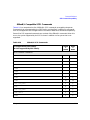
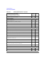
SCPI Command Compatibility . . . . . . . . . . . . . . . . . . . . . . . . . . . . . . . . . . . . . . . . . . .
:SYSTem:IDN . . . . . . . . . . . . . . . . . . . . . . . . . . . . . . . . . . . . . . . . . . . . . . . . . . . . . . .
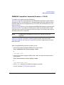
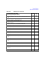
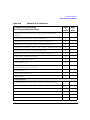
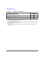
8340B/41B Compatible Commands (firmware ≥ C.01.21) . . . . . . . . . . . . . . . . . . . .
836xxB/L Compatible SCPI Commands . . . . . . . . . . . . . . . . . . . . . . . . . . . . . . . . . .
8373xB and 8371xB Compatible SCPI Commands . . . . . . . . . . . . . . . . . . . . . . . . .
294
294
295
309
327
xiii
Contents
xiv
1
Getting Started
1
Getting Started
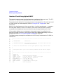
Introduction to Remote Operation
Introduction to Remote Operation
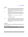
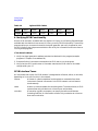
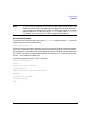
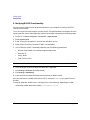
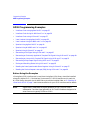
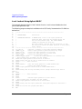
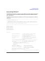
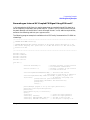
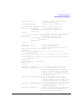
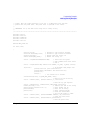
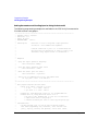
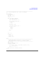
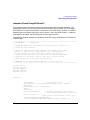
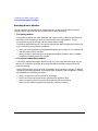
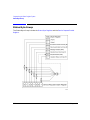
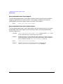
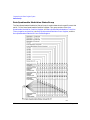
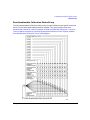
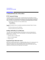
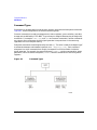
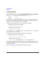
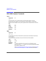
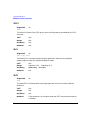
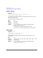
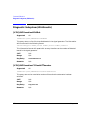
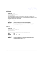
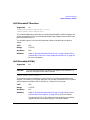
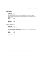
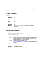
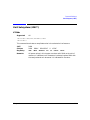
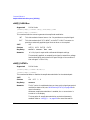
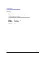
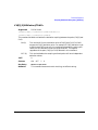
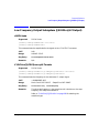
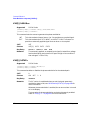
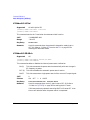
PSG family signal generators support the following interfaces:
• General Purpose Interface Bus (GPIB)
• Local Area Network (LAN)
• ANSI/EIA232 (RS-232) serial connection
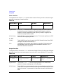
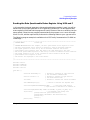
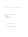
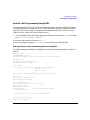
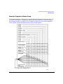
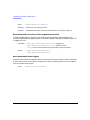
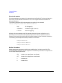
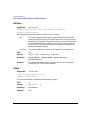
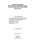
Each of these interfaces, in combination with an IO library and programming language, can
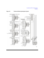
be used to remotely control the signal generator. Figure 1-1 uses the GPIB as an example of
the relationships between the interface, IO libraries, programming language, and signal
generator.
Figure 1-1
2
Software/Hardware Layers
Chapter 1
Getting Started
Introduction to Remote Operation
Interfaces
GPIB
GPIB is used extensively when a dedicated computer is available for remote
control of each instrument or system. Data transfer is fast because the GPIB
handles information in 8-bit bytes. GPIB is physically restricted by the
location and distance between the instrument/system and the computer;
cables are limited to an average length of two meters per device with a total
length of 20 meters.
LAN
LAN based communication is supported by the signal generator. Data
transfer is fast as the LAN handles packets of data. The distance between a
computer and the signal generator is limited to 100 meters (10BASE-T). The
following protocols can be used to communicate with the signal generator
over the LAN:
• VMEbus Extensions for Instrumentation (VXI) as defined in VXI-11
• Sockets LAN
• Telephone Network (TELNET)
• File Transfer Protocol (FTP)
RS-232
RS-232 is a common method used to communicate with a single instrument;
its primary use is to control printers and external disk drives, and connect to
a modem. Communication over RS-232 is much slower than with GPIB or
LAN because data is sent and received one bit at a time. It also requires that
certain parameters, such as baud rate, be matched on both the computer
and signal generator.
IO Libraries
An IO library is a collection of functions used by a programming language to send instrument
commands. An IO library must be installed on your computer before writing any programs to
control the signal generator.
NOTE
Chapter 1
Agilent IO libraries support the VXI-11 standard.
3
Getting Started
Introduction to Remote Operation
Programming Language
The programming language is used along with Standard Commands for Programming
Instructions (SCPI) and IO library functions to remotely control the signal generator.
Common programming languages include:
• C/C++
• Agilent BASIC
• LabView
• Java
Java is a U.S. trademark of Sun Microsystems, Inc.
4
Chapter 1
Getting Started
Using GPIB
Using GPIB
The GPIB allows instruments to be connected together and controlled by a computer. The
GPIB and its associated interface operations are defined in the ANSI/IEEE Standard
488.1-1987 and ANSI/IEEE Standard 488.2-1992. See the IEEE website, www.ieee.org, for
details on these standards.
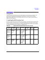
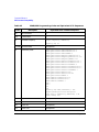
1. Installing the GPIB Interface Card
A GPIB interface card must be installed in your computer. Two common GPIB interface cards
are the National Instruments (NI) PCI–GPIB and the Agilent GPIB interface cards. Follow
the GPIB interface card instructions for installing and configuring the card in your computer.
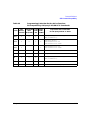
The following tables provide information on interface cards.
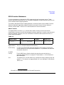
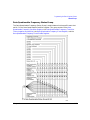
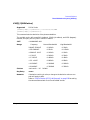
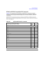
Table 1-1
Interface
Card
Agilent GPIB Interface Card for PC-Based Systems
Operating
System
IO
Library
Agilent
82341C for
ISA bus
computers
Windows
95/98/NT/
2000®
VISA /
SICL
Agilent
82341D
Plug&Play
for PC
Windows
95
Agilent
82350A for
PCI bus
computers
Windows
95/98/NT/
2000
Languages
Backplane
/BUS
Max IO
(kB/sec)
Buffering
C/C++, Visual
Basic, Agilent
VEE, Agilent
Basic for
Windows
ISA/EISA,
16 bit
750
Built-in
VISA /
SICL
C/C++, Visual
Basic, Agilent
VEE, Agilent
Basic for
Windows
ISA/EISA,
16 bit
750
Built-in
VISA /
SICL
C/C++, Visual
Basic, Agilent
VEE, Agilent
Basic for
Windows
PCI 32 bit
750
Built-in
Windows 95, 98, NT and 2000 are registered trademarks of Microsoft Corporation
Chapter 1
5
Getting Started
Using GPIB
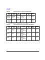
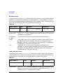
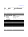
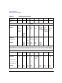
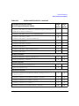
Table 1-2
NI-GPIB Interface Card for PC-Based Systems
Interface
Card
Operating
System
IO
Library
Languages
Backplane
/BUS
Max IO
National
Instrument’s
PCI-GPIB
Windows
95/98/2000/
ME/NT
VISA
NI-488.2
C/C++,
Visual BASIC,
LabView
PCI 32 bit
1.5
Mbytes/s
National
Instrument’s
PCI-GPIB+
Windows
NT
VISA
NI-488.2
C/C++,
Visual BASIC,
LabView
PCI 32 bit
1.5
Mbytes/s
NI-488.2 is a trademark of National Instruments Corporation
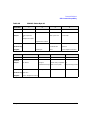
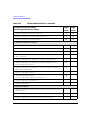
Table 1-3
Interface
Card
Agilent-GPIB Interface Card for HP-UX Workstations
Operating
System
IO
Library
Languages
Agilent
E2071C
HP-UX 9.x,
HP-UX
10.01
VISA/SICL
Agilent
E2071D
HP-UX
10.20
Agilent
E2078A
HP-UX
10.20
6
Backplane
/BUS
Max IO
(kB/sec)
Buffering
ANSI C,
Agilent VEE,
Agilent BASIC,
HP-UX
EISA
750
Built-in
VISA/SICL
ANSI C,
Agilent VEE,
Agilent BASIC,
HP-UX
EISA
750
Built-in
VISA/SICL
ANSI C,
Agilent VEE,
Agilent BASIC,
HP-UX
PCI
750
Built-in
Chapter 1
Getting Started
Using GPIB
2. Selecting IO Libraries for GPIB
The IO libraries are included with your GPIB interface card. These libraries can also be
downloaded from the National Instruments website or the Agilent website. The following is a
discussion on these libraries.
VISA
VISA is an IO library used to develop IO applications and instrument
drivers that comply with industry standards. It is recommended that the
VISA library be used for programming the signal generator. The NI-VISA
and Agilent VISA libraries are similar implementations of VISA and have
the same commands, syntax, and functions. The differences are in the lower
level IO libraries; NI-488.2 and SICL respectively. It is best to use the
Agilent VISA library with the Agilent GPIB interface card or NI-VISA with
the NI PCI-GPIB interface card.
SICL
Agilent SICL can be used without the VISA overlay. The SICL functions can
be called from a program. However, if this method is used, executable
programs will not be portable to other hardware platforms. For example, a
program using SICL functions will not run on a computer with NI libraries
(PCI-GPIB interface card).
NI-488.2
NI-488.2 can be used without the VISA overlay. The NI-488.2 functions can
be called from a program. However, if this method is used, executable
programs will not be portable to other hardware platforms. For example, a
program using NI-488.2 functions will not run on a computer with Agilent
SICL (Agilent GPIB interface card).
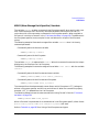
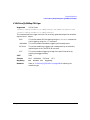
3. Setting Up the GPIB Interface
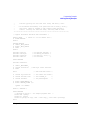
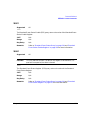
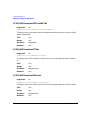
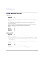
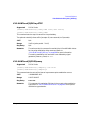
1. Press Utility > GPIB/RS-232 > GPIB Address.
2. Use the numeric keypad, the arrow keys, or rotate the front panel knob to set the desired
address.
The signal generator’s GPIB address is set to 19 at the factory. The acceptable range of
addresses is 0 through 30. Once initialized, the state of the GPIB address is not affected by
a signal generator preset or by a power cycle. Other instruments on the GPIB cannot use
the same address as the signal generator.
3. Press Enter.
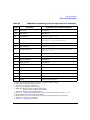
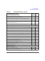
4. Connect a GPIB interface cable between the signal generator and the computer. (Refer to
Table 1-4 for cable part numbers.)
NI-VISA is a registered trademark of National Instruments Corporation
Chapter 1
7
Getting Started
Using GPIB
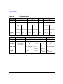
Table 1-4
Agilent GPIB Cables
Model
10833A
10833B
10833C
10833D
10833F
10833G
Length
1 meter
2 meters
4 meters
.5 meter
6 meters
8 meters
4. Verifying GPIB Functionality
Use the VISA Assistant, available with the Agilent IO Library or the Getting Started Wizard
available with the National Instrument IO Library, to verify GPIB functionality. These utility
programs allow you to communicate with the signal generator and verify its operation over
the GPIB. Refer to the Help menu available in each utility for information and instructions on
running these programs.
If You Have Problems
1. Verify the signal generator’s address matches that declared in the program (example
programs in Chapter 2 use address 19).
2. Remove all other instruments connected to the GPIB and re-run the program.
3. Verify that the GPIB card’s name or id number matches the GPIB name or id number
configured for your PC.
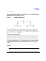
GPIB Interface Terms
An instrument that is part of a GPIB network is categorized as a listener, talker, or controller,
depending on its current function in the network.
listener
A listener is a device capable of receiving data or commands from other
instruments. Several instruments in the GPIB network can be listeners
simultaneously.
talker
A talker is a device capable of transmitting data. To avoid confusion, a GPIB
system allows only one device at a time to be an active talker.
controller
A controller, typically a computer, can specify the talker and listeners
(including itself) for an information transfer. Only one device at a time can
be an active controller.
8
Chapter 1
Getting Started
Using GPIB
GPIB Function Statements
Function statements are the basis for GPIB programming and instrument control. These
function statements combined with SCPI provide management and data communication for the
GPIB interface and the signal generator.
This section describes functions used by different IO libraries. Refer to the NI-488.2 Function
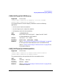
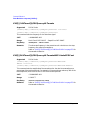
Reference Manual for Windows, Agilent Standard Instrument Control Library reference
manual, and Microsoft® Visual C++ 6.0 documentation for more information.
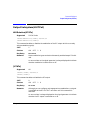
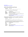
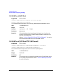
Abort Function
The Agilent BASIC function ABORT and the other listed IO library functions terminate
listener/talker activity on the GPIB and prepare the signal generator to receive a new command
from the computer. Typically, this is an initialization command used to place the GPIB in a
known starting condition.
Table 1-5
Agilent BASIC
VISA
NI-488.2
Agilent SICL
10 ABORT 7
viTerminate (parameter
list)
ibstop(int ud)
iabort (id)
Agilent BASIC
The ABORT function stops all GPIB activity.
VISA Library
In VISA, the viTerminate command requests a VISA session to terminate
normal execution of an asynchronous operation. The parameter list describes
the session and job id.
NI-488.2
Library
SICL
The NI-488.2 library function aborts any asynchronous read, write, or
command operation that is in progress. The parameter ud is the interface or
device descriptor.
The Agilent SICL function aborts any command currently executing with the
session id. This function is supported with C/C++ on Windows 3.1 and Series
700 HP-UX.
Microsoft is a registered trademark of Microsoft Corporation.
Chapter 1
9
Getting Started
Using GPIB
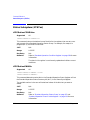
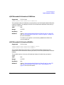
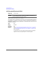
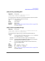
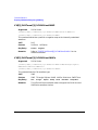
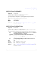
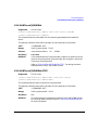
Remote Function
The Agilent BASIC function REMOTE and the other listed IO library functions cause the signal
generator to change from local operation to remote operation. In remote operation, the front
panel keys are disabled except for the Local key and the line power switch. Pressing the Local
key on the signal generator front panel restores manual operation.
Table 1-6
Agilent BASIC
VISA
NI-488.2
Agilent SICL
10 REMOTE 719
N/A
EnableRemote (parameter
list)
iremote (id)
Agilent BASIC
The REMOTE 719 function disables the front panel operation of all keys with
the exception of the Local key.
VISA Library
The VISA library, at this time, does not have a similar command.
NI-488.2
Library
SICL
This NI-488.2 library function asserts the Remote Enable (REN) GPIB line.
All devices listed in the parameter list are put into a listen-active state
although no indication is generated by the signal generator. The parameter
list describes the interface or device descriptor.
The Agilent SICL function puts an instrument, identified by the id
parameter, into remote mode and disables the front panel keys. Pressing the
Local key on the signal generator front panel restores manual operation.
The parameter id is the session identifier.
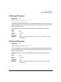
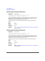
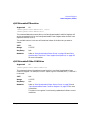
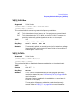
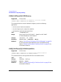
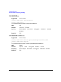
Local Lockout Function
The Agilent BASIC function LOCAL LOCKOUT and the other listed IO library functions can be
used to disable the front panel keys including the Local key. With the Local key disabled, only
the controller (or a hard reset of the line power switch) can restore local control.
Table 1-7
Agilent BASIC
VISA
NI-488.2
Agilent SICL
10 LOCAL LOCKOUT 719
N/A
SetRWLS (parameter
list)
igpibllo (id)
Agilent BASIC
10
The LOCAL LOCKOUT function disables all front-panel signal generator keys.
Return to local control can occur only with a hard on/off, when the LOCAL
command is sent or if the Preset key is pressed.
Chapter 1
Getting Started
Using GPIB
VISA Library
NI-488.2
Library
SICL
The VISA library, at this time, does not have a similar command.
The NI-488.2 library function places the instrument described in the
parameter list in remote mode by asserting the Remote Enable (REN) GPIB
line. The lockout state is then set using the Local Lockout (LLO) GPIB
message. Local control can be restored only with the EnableLocal NI-488.2
routine or hard reset. The parameter list describes the interface or device
descriptor.
The Agilent SICL igpibllo function prevents user access to front panel keys
operation. The function puts an instrument, identified by the id parameter,
into remote mode with local lockout. The parameter id is the session
identifier and instrument address list.
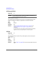
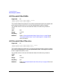
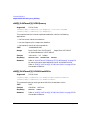
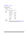
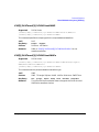
Local Function
The Agilent BASIC function LOCAL and the other listed functions cause the signal generator
to return to local control with a fully enabled front panel.
Table 1-8
Agilent BASIC
VISA
NI-488.2
Agilent SICL
10 LOCAL 719
N/A
ibloc (int ud)
iloc(id)
Agilent BASIC
The LOCAL 719 function returns the signal generator to manual operation,
allowing access to the signal generator’s front panel keys.
VISA Library
The VISA library, at this time, does not have a similar command.
NI-488.2
Library
SICL
Chapter 1
The NI-488.2 library function places the interface in local mode and allows
operation of the signal generator’s front panel keys. The ud parameter in the
parameter list is the interface or device descriptor.
The Agilent SICL function puts the signal generator into Local operation;
enabling front panel key operation. The id parameter identifies the session.
11
Getting Started
Using GPIB
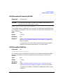
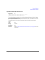
Clear Function
The Agilent BASIC function CLEAR and the other listed IO library functions cause the signal
generator to assume a cleared condition.
Table 1-9
Agilent BASIC
VISA
NI-488.2
Agilent SICL
10 CLEAR 719
viClear(ViSession
vi)
ibclr(int ud)
iclear (id)
Agilent BASIC
The CLEAR 719 function causes all pending output-parameter operations to
be halted, the parser (interpreter of programming codes) to reset and
prepare for a new programming code, stops any sweep in progress, and
continuous sweep to be turned off.
VISA Library
The VISA library uses the viClear function. This function performs an IEEE
488.1 clear of the signal generator.
NI-488.2
Library
SICL
The NI-488.2 library function sends the GPIB Selected Device Clear (SDC)
message to the device described by ud.
The Agilent SICL function clears a device or interface. The function also
discards data in both the read and write formatted IO buffers. The id
parameter identifies the session.
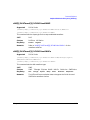
Output Function
The Agilent BASIC IO function OUTPUT and the other listed IO library functions put the signal
generator into a listen mode and prepare it to receive ASCII data, typically SCPI commands.
Table 1-10
Agilent BASIC
VISA
NI-488.2
Agilent SICL
10 OUTPUT 719
viPrintf(parameter
list)
ibwrt(parameter
list)
iprintf (parameter
list)
Agilent BASIC
The function OUTPUT 719 puts the signal generator into remote mode,
makes it a listener, and prepares it to receive data.
VISA Library
The VISA library uses the above function and associated parameter list to
output data. This function formats according to the format string and sends
data to the device. The parameter list describes the session id and data to
send.
12
Chapter 1
Getting Started
Using GPIB
NI-488.2
Library
SICL
The NI-488.2 library function addresses the GPIB and writes data to the
signal generator. The parameter list includes the instrument address,
session id, and the data to send.
The Agilent SICL function converts data using the format string. The format
string specifies how the argument is converted before it is output. The
function sends the characters in the format string directly to the
instrument. The parameter list includes the instrument address, data buffer
to write, and so forth.
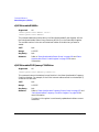
Enter Function
The Agilent BASIC function ENTER reads formatted data from the signal generator. Other IO
libraries use similar functions to read data from the signal generator.
Table 1-11
Agilent BASIC
VISA
NI-488.2
Agilent SICL
10 ENTER 719;
viScanf (parameter
list)
ibrd (parameter list)
iscanf (parameter list)
Agilent BASIC
The function ENTER 719 puts the signal generator into remote mode, makes
it a talker, and assigns data or status information to a designated variable.
VISA Library
The VISA library uses the viScanf function and an associated parameter list
to receive data. This function receives data from the instrument, formats it
using the format string, and stores the data in the argument list. The
parameter list includes the session id and string argument.
NI-488.2
Library
SICL
Chapter 1
The NI-488.2 library function addresses the GPIB, reads data bytes from
the signal generator, and stores the data into a specified buffer. The
parameter list includes the instrument address and session id.
The Agilent SICL function reads formatted data, converts it, and stores the
results into the argument list. The conversion is done using conversion rules
for the format string. The parameter list includes the instrument address,
formatted data to read, and so forth.
13
Getting Started
Using LAN
Using LAN
The signal generator can be remotely programmed via a LAN interface and LAN-connected
computer using one of several LAN interface protocols. The LAN allows instruments to be
connected together and controlled by a LAN-based computer. LAN and its associated interface
operations are defined in the IEEE 802.2 standard. See the IEEE website for more details.
The signal generator supports the following LAN interface protocols:
• VXI-11
• Sockets LAN
• Telephone Network (TELNET)
• File Transfer Protocol (FTP)
VXI-11 and sockets LAN are used for general programming using the LAN interface,
TELNET is used for interactive, one command at a time instrument control, and FTP is for
file transfer.
1. Selecting IO Libraries for LAN
The TELNET and FTP protocols do not require IO libraries to be installed on your computer.
However, to write programs to control your signal generator, an I/O library must be installed
on your computer and the computer configured for instrument control using the LAN
interface.
The IO libraries can be downloaded from the Agilent website. The following is a discussion on
these libraries.
Agilent VISA
VISA is an IO library used to develop IO applications and instrument
drivers that comply with industry standards. Use the Agilent VISA library
for programming the signal generator over the LAN interface.
SICL
Agilent SICL is a lower level library that is installed along with Agilent
VISA.
14
Chapter 1
Getting Started
Using LAN
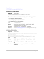
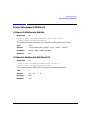
2. Setting Up the LAN Interface
For LAN operation, an IP address must be assigned to the signal generator and the signal
generator connected to the LAN. Your IT administrator can issue a hostname and IP address
for the signal generator.
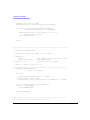
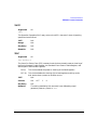
1. Press Utility > GPIB/RS-232 LAN > LAN Setup.
2. Press Hostname.
Use the alphanumeric softkeys to enter a hostname. The name is not case sensitive.
3. Press Enter.
4. Press IP Address.
Use the left and right arrow keys to move the cursor. Use the up and down arrow keys, the
front panel knob or the numeric keypad to enter an IP address. You can press the Clear Text
softkey to erase the current address.
5. Press Enter and then cycle the signal generator’s power, using the LINE switch.
This assigns a hostname and IP address to the signal generator. The hostname and IP
address are not affected by an instrument preset or by a power cycle.
6. Connect the signal generator to the LAN using a 10BASE-T LAN cable.
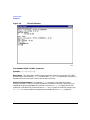
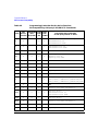
3. Verifying LAN Functionality
Verify the communications link between the computer and the signal generator remote file
server using the ping utility. Compare your ping response to those described in Table 1-12.
From a UNIX ® workstation, type:
ping hostname 64 10
where hostname is your instruments name and 64 is the packet size, and 10 is the number of
packets transmitted. Type man ping at the UNIX prompt for details on the ping command.
From the MS-DOS® Command Prompt or Windows environment, type:
ping -n 10 hostname
where hostname is your instruments name and 10 is the number of echo requests. Type ping
at the command prompt for details on the ping command.
UNIX is a registered trademark of the Open Group
MS-DOS is a registered trademark of Microsoft Corporation
Chapter 1
15
Getting Started
Using LAN
Table 1-12
Ping Responses
Normal Response
for UNIX
A normal response to the ping command will be a total of 9 or 10
packets received with a minimal average round-trip time. The
minimal average will be different from network to network. LAN
traffic will cause the round-trip time to vary widely.
Normal Response
for DOS or Windows
A normal response to the ping command will be a total of 9 or 10
packets received if 10 echo requests were specified.
Error Messages
If error messages appear, then check the command syntax before
continuing with troubleshooting. If the syntax is correct, resolve the
error messages using your network documentation or by consulting
your network administrator.
If an unknown host error message appears, try using the IP address
instead of the hostname. Also, verify that the host name and IP
address for the signal generator have been registered by your IT
administrator.
Check that the hostname and IP address are correctly entered in
the node names database. To do this, enter the nslookup
<hostname> command from the command prompt.
No Response
If there is no response from a ping, no packets were received. Check
that the typed address or hostname matches the IP address or
hostname assigned to the signal generator in the System Utility >
GPIB/RS-232 LAN > LAN Setup menu.
Ping each node along the route between your workstation and the
signal generator, starting with your workstation. If a node doesn’t
respond, contact your IT administrator.
If the signal generator still does not respond to ping, you should
suspect a hardware problem.
Intermittent
Response
16
If you received 1 to 8 packets back, there maybe a problem with the
network. In networks with switches and bridges, the first few pings
may be lost until the these devices ‘learn’ the location of hosts. Also,
because the number of packets received depends on your network
traffic and integrity, the number might be different for your
network. Problems of this nature are best resolved by your IT
department.
Chapter 1
Getting Started
Using LAN
Using VXI-11
The signal generator supports the LAN interface protocol described in the VXI-11 standard.
VXI-11 is an instrument control protocol based on Open Network Computing/Remote
Procedure Call (ONC/RPC) interfaces running over TCP/IP. It is intended to provide GBIB
capabilities such as SRQ (Service Request), status byte reading, and DCAS (Device Clear
State) over a LAN interface. This protocol is a good choice for migrating from GPIB to LAN as
it has full Agilent VISA/SICL support. See the VXI website, www.vsi.org, for more information
and details on the specification.
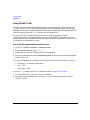
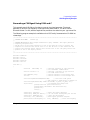
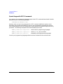
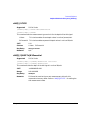
Configuring for VXI-11
The Agilent IO library has a program, IO Config, that is used to setup the computer/signal
generator interface for the VXI-11 protocol. Download the latest version of the Agilent IO
library from the Agilent website. Refer to the Agilent IO library user manual, documentation,
and Help menu for information on running the IO Config program and configuring the VXI-11
interface.
Use the IO Config program to configure the LAN client. Once the computer is configured for a
LAN client, you can use the VXI-11 protocol and the VISA library to send SCPI commands to
the signal generator over the LAN interface. Example programs for this protocol are included
in “LAN Programming Examples” on page 64 of this programming guide.
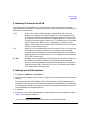
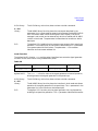
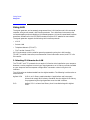
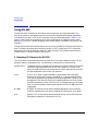
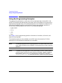
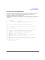
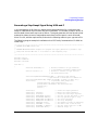
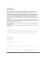
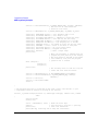
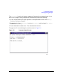
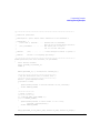
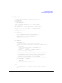
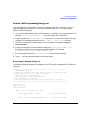
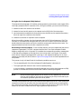
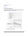
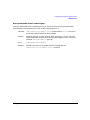
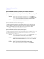
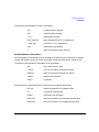
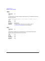
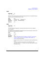
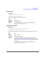
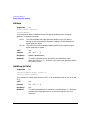
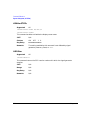
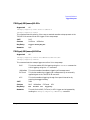
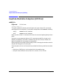
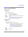
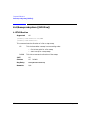
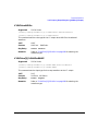
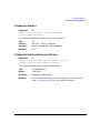
NOTE
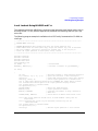
Chapter 1
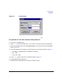
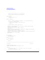
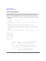
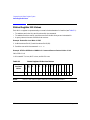
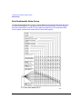
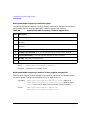
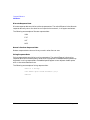
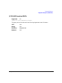
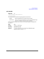
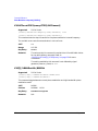
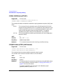
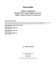
For Agilent IO library version J.01.0100, the “identify devices at run-time”
check box must be unchecked. Refer to Figure 1-2.
17
Getting Started
Using LAN
Figure 1-2
18
Show Devices Form
Chapter 1
Getting Started
Using LAN
Using Sockets LAN
Sockets LAN is a method used to communicate with the signal generator over the LAN
interface using the Transmission Control Protocol/ Internet Protocol (TCP/IP). A socket is a
fundamental technology used for computer networking and allows applications to
communicate using standard mechanisms built into network hardware and operating
systems. The method accesses a port on the signal generator from which bidirectional
communication with a network computer can be established.
Sockets LAN can be described as an internet address that combines the Internet Protocol (IP)
with a device port number and represents a single connection between two pieces of software.
The socket can be accessed using code libraries packaged with the computer operating system.
Two common versions of socket libraries are the Berkeley Sockets Library for UNIX systems
and Winsock for Microsoft operating systems.
Your signal generator implements a sockets Applications Programming Interface (API) that is
compatible with Berkeley sockets, for UNIX systems, and Winsock for Microsoft systems. The
signal generator is also compatible with other standard sockets APIs. The signal generator
can be controlled using SCPI commands that are output to a socket connection established in
your program.
Before you can use sockets LAN, you must select the signal generator’s sockets port number to
use:
• Standard mode. Available on port 7777. Use this port for simple programming.
• TELNET mode. Available on port 7778.
An example using sockets LAN is given in Chapter 2 of this programming guide.
Chapter 1
19
Getting Started
Using LAN
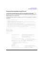
Using TELNET LAN
TELNET provides a means of communicating with the signal generator over the LAN. The
TELNET client, run on a LAN connected computer, will create a login session on the signal
generator. A connection, established between computer and signal generator, generates a user
interface display screen with SCPI> prompts on the command line.
Using the TELNET protocol to send commands to the signal generator is similar
communicating with the signal generator over GPIB. You establish a connection with the
signal generator and then send or receive information using SCPI commands. Communication
is interactive: one command at a time.
Using TELNET and MS-DOS Command Prompt
1. On the PC click Start > Programs > Command Prompt.
2. At the command prompt, type in telnet.
3. Press enter. The TELNET display screen will be displayed.
4. Click on the Connect menu then select Remote System. A connection form will be displayed.
Refer to Figure 1-3.
5. Enter the hostname, port number, and TermType then click Connect. Refer to Figure 1-3.
• Host Name - IP address or hostname
• Port - 7778
• Term Type - vt100
6. At the SCPI> prompt, enter SCPI commands. Refer to Figure 1-4 on page 22.
7. To signal device clear, press Ctrl-C on your keyboard.
8. Select Exit from the Connect menu and type exit at the command prompt to end the
TELNET session.
20
Chapter 1
Getting Started
Using LAN
Figure 1-3
Connect Form
Using TELNET On a PC With a Host/Port Setting Menu GUI
1. On your PC click Start > Run.
2. Type telnet then click the Ok button. The TELNET connection screen will be displayed.
3. Click on the Connect menu then select Remote System. A connection form will be displayed.
Refer to Figure 1-3.
4. Enter the hostname, port number, and TermType then click Connect. Refer to Figure 1-3.
• Host Name - signal generator’s IP address or hostname
• Port - 7778
• Term Type - vt100
5. At the SCPI> prompt, enter SCPI commands. Refer to Figure 1-4.
6. To signal device clear, press Ctrl-C.
7. Select Exit from the Connect menu to end the TELNET session.
Chapter 1
21
Getting Started
Using LAN
Figure 1-4
TELNET Window
The Standard UNIX TELNET Command
Synopsis telnet [host [port]]
Description This command is used to communicate with another host using the TELNET
protocol. When the command telnet is invoked with host or port arguments, a connection is
opened to the host, and input is sent from the user to the host.
Options and Parameters The command telnet operates in character-at-a-time or
line-by-line mode. In line-by-line mode, typed text is echoed to the screen. When the line is
completed (by pressing the Enter key), the text line is sent to host. In character-at-a-time
mode, text is echoed to the screen and sent to host as it is typed. At the UNIX prompt, type
man telnet to view the options and parameters available with the telnet command.
22
Chapter 1
Getting Started
Using LAN
NOTE
If your TELNET connection is in line-by-line mode, there is no local echo. This
means you cannot see the characters you are typing until you press the Enter
key. To remedy this, change your TELNET connection to character-by-character
mode. Escape out of TELNET and, at the telnet> prompt, type mode char. If
this does not work, consult your TELNET program’s documentation.
Unix TELNET Example
To connect to the instrument with host name myInstrument and port number 7778, enter the
following command on the command line:
telnet myInstrument 7778
When you connect to the signal generator, the UNIX window will display a welcome message
and a SCPI command prompt. The instrument is now ready to accept your SCPI commands.
As you type SCPI commands, query results appear on the next line. When you are done, break
the TELNET connection using an escape character. For example, Ctrl -],where the control key
and the ] are pressed at the same time.
The following example shows TELNET commands:
$ telnet myinstrument 7778
Trying....
Connected to signal generator
Escape character is ‘^]’.
Agilent Technologies, E8254A SN-US00000001
Firmware:
Hostname: your instrument
IP :xxx.xx.xxx.xxx
SCPI>
Chapter 1
23
Getting Started
Using LAN
Using FTP
FTP allows users to transfer files between the signal generator and any computer connected
to the LAN. For example, you can use FTP to download instrument screen images to a
computer. When logged onto the signal generator with the FTP command, the signal
generator’s file structure can be accessed. Figure 1-5 shows the FTP interface and lists the
directories in the signal generator’s user level directory.
NOTE
Figure 1-5
24
File access is limited to the signal generator’s /user directory.
FTP Screen
Chapter 1
Getting Started
Using LAN
The following steps outline a sample FTP session from the MS-DOS Command Prompt:
1. On the PC click Start > Programs > Command Prompt.
2. At the command prompt enter:
ftp < IP address > or < hostname >
3. At the user name prompt, press enter.
4. At the password prompt, press enter.
You are now in the signal generator’s user directory. Typing help at the command prompt
will show you the FTP commands that are available on your system.
5. Type quit or bye to end your FTP session.
Chapter 1
25
Getting Started
Using RS-232
Using RS-232
The RS-232 serial interface can be used to communicate with the signal generator. The
RS-232 connection is standard on most PCs and can be connected to the signal generator’s
rear-panel AUXILIARY INTERFACE connector using the cable described in Table 1-13 on
page 27. Many functions provided by GPIB, with the exception of indefinite blocks, serial
polling, GET, non-SCPI remote languages, and remote mode are available using the RS-232
interface.
The serial port sends and receives data one bit at a time, therefore RS-232 communication is
slow. The data transmitted and received is usually in ASCII format with SCPI commands
being sent to the signal generator and ASCII data returned. The interface uses three-line
communication: Transmit, Receive, and Ground.
1. Selecting IO Libraries for RS-232
The IO libraries can be downloaded from the National Instrument website, www.ni.com, or
Agilent’s website, www.agilent.com. The following is a discussion on these libraries.
Agilent BASIC
The Agilent BASIC language has an extensive IO library that can be used to
control the signal generator over the RS-232 interface. This library has
many low level functions that can be used in BASIC applications to control
the signal generator over the RS-232 interface.
VISA
VISA is an IO library used to develop IO applications and instrument
drivers that comply with industry standards. It is recommended that the
VISA library be used for programming the signal generator. The NI-VISA
and Agilent VISA libraries are similar implementations of VISA and have
the same commands, syntax, and functions. The differences are in the lower
level IO libraries used to communicate over the RS-232; NI-488.2 and SICL
respectively.
NI-488.2
NI-488.2 IO libraries can be used to develop applications for the RS-232
interface. See National Instrument’s website for information on NI-488.2.
SICL
Agilent SICL can be used to develop applications for the RS-232 interface.
See Agilent’s website for information on SICL.
26
Chapter 1
Getting Started
Using RS-232
2. Setting Up the RS-232 Interface
1. Press Utility > GPIB/RS-232 > RS-232 Baud Rate > 9600
Use baud rates 57600 or lower only. Select the signal generator’s baud rate to match the
baud rate of your computer or UNIX workstation or adjust the baud rate settings on your
computer to match the baud rate setting of the signal generator.
NOTE
The default baud rate for VISA is 9600. This baud rate can be changed with
the “VI_ATTR_ASRL_BAUD” VISA attribute.
2. Press Utility > GPIB/RS-232 > RS-232 Setup > Trans/Recv Pace None Xon until None is
highlighted.
The signal generator does not support hardware handshake. Software flow control is
enabled with the Xon selection in the above key menu.
3. Press Utility > GPIB/RS-232 > RS-232 Echo Off On until Off is highlighted.
Set the signal generator’s RS-232 echo. Selecting On echoes or returns characters sent to
the signal generator and prints them to the display.
4. Connect an RS-232 cable from the computer’s serial connector to the signal generator’s
AXILLARY INTERFACE connector. Refer to Table 1-13 for RS-232 cable information.
Table 1-13
RS-232 Serial Interface Cable
Quantity
Description
Agilent Part Number
1
Serial RS-232 cable 9-pin (male) to
9-pin (female)
8120-6188
NOTE
Chapter 1
Any 9 pin (male) to 9 pin (female) straight-through cable that directly wires
pins 2,3, and 5 may be used.
27
Getting Started
Using RS-232
3. Verifying RS-232 Functionality
You can use the HyperTerminal program available on your computer to verify the RS-232
interface functionality.
To run the HyperTerminal program, connect the RS-232 cable between the computer and the
signal generator, set the signal generator’s baud rate to 9600, and perform the following steps:
1. On the PC click Start >Programs > Accessories > HyperTerminal.
2. Select HyperTerminal.
3. Enter a name for the session in the text box and select an icon.
4. Select COM1 (COM2 can be used if COM1 is unavailable).
5. In the COM1(or COM2, if selected) properties, set the following parameters:
•
Bits per second: 9600 must match computer’s baud rate
•
Data bits: 8
•
Parity: None
•
Flow Control: None
NOTE
With software flow control the user cannot transmit binary data (file IO).
6. Go to the HyperTerminal window and select File > Properties
7. Go to Settings > Emulation and select VT100.
8. Go to Settings > ASCII Setup.
9. Check the first two boxes and leave the other boxes as default values.
Once the connection is established, enter the SCPI command *IDN? in the HyperTerminal
window.
The signal generator should return a string similar to the following, depending on model:
<instrument model name and number>, US37040098 B.03.00
28
Chapter 1
Getting Started
Using RS-232
If You Have Problems
1. Verify that the baud rate, parity, stop bits, and flow control are the same for the computer
and signal generator.
2. Verify that the RS-232 cable is identical to the cable specified in Table 1-13.
3. Verify that the application is using the correct computer COM port and that the RS-232
cable is properly connected to that port.
Character Format Parameters
The signal generator uses the following character format parameters when communicating
via RS-232:
• Character Length: Eight data bits are used for each character, excluding start, stop, and
parity bits.
• Parity Enable: Parity is disabled (absent) for each character.
• Stop Bits: One stop bit is included with each character.
• Software flow control or no Software flow control.
Chapter 1
29
Getting Started
Using RS-232
30
Chapter 1
2 Programming Examples
31
Programming Examples
Using the Programming Examples
Using the Programming Examples
The programming examples for remote control of the signal generator use the GPIB, LAN,
and RS-232 interfaces and demonstrate instrument control using different I/O libraries and
programming languages. Many of the example programs in this chapter are interactive; the
user will be prompted to perform certain actions or verify signal generator operation or
functionality. Example programs are written in the following languages:
• Agilent BASIC
• C/C++
• Java
• PERL
See Chapter 1 of this programming guide for information on interfaces, I/O libraries, and
programming languages.
The example programs are also available on the PSG Family Documentation CD-ROM,
allowing you to cut and paste the examples into a text editor.
NOTE
The example programs set the signal generator into remote mode; front panel
keys, except the Local key, are disabled. Press the Local key to revert to manual
operation.
NOTE
To update the signal generator’s front panel display so that it reflects remote
command setups, enable the remote display: press Utility > Display > Update in
Remote Off On softkey until On is highlighted or send the SCPI command
:DISPlay:REMote ON. For faster test execution, disable front panel updates.
32
Chapter 2
Programming Examples
Using the Programming Examples
Programming Examples Development Environment
The C/C++ examples in this guide were written using an IBM-compatible personal computer
(PC) with the following configuration:
• Pentium® processor
• Windows NT 4.0 operating system
• C/C++ programming language with the Microsoft Visual C++ 6.0 IDE
• National Instruments PCI- GPIB interface card or Agilent GPIB interface card
• National Instruments VISA Library or Agilent VISA library
• COM1 or COM2 serial port available
• LAN interface card
The Agilent BASIC examples were run on a UNIX 700 Series workstation
Running C/C++ Programming Examples
To run the example programs written in C/C++ you must include the required files in the
Microsoft Visual C++ 6.0 project.
If you are using the VISA library do the following:
• add the visa32.lib file to the Resource Files
• add the visa.h file to the Header Files
If you are using the NI-488.2 library do the following:
• add the GPIB-32.OBJ file to the Resource Files
• add the windows.h file to the Header Files
• add the Deci-32.h file to the Header Files
Refer to the National Instrument website for information on the NI-488.2 library and file
requirements. For information on the VISA library see the Agilent website or National
Instrument’s website.
Pentium is a U.S. registered trademark of Intel Corporation
Chapter 2
33
Programming Examples
GPIB Programming Examples
GPIB Programming Examples
• “Interface Check using Agilent BASIC” on page 35
• “Interface Check Using NI-488.2 and C++” on page 36
• “Interface Check using VISA and C” on page 37
• “Local Lockout Using Agilent BASIC” on page 38
• “Local Lockout Using NI-488.2 and C++” on page 39
• “Queries Using Agilent BASIC” on page 41
• “Queries Using NI-488.2 and C++” on page 43
• “Queries Using VISA and C” on page 45
• “Generating a CW Signal Using VISA and C” on page 47
• “Generating an Externally Applied AC-Coupled FM Signal Using VISA and C” on page 49
• “Generating an Internal AC-Coupled FM Signal Using VISA and C” on page 51
• “Generating a Step-Swept Signal Using VISA and C” on page 53
• “Saving and Recalling States Using VISA and C” on page 55
• “Reading the Data Questionable Status Register Using VISA and C” on page 57
• “Reading the Service Request Interrupt (SRQ) Using VISA and C” on page 60
Before Using the Examples
If the Agilent GPIB interface card is used, then the Agilent VISA library should be installed
along with Agilent SICL. If the National Instruments PCI-GPIB interface card is used, the
NI-VISA library along with the NI-488.2 library should be installed. Refer to “2. Selecting IO
Libraries for GPIB” on page 7 and the documentation for your GPIB interface card for details.
NOTE
34
Agilent BASIC addresses the signal generator at 719. The GPIB card is
addressed at 7 and the signal generator at 19. The GPIB address designator for
other libraries is typically GPIB0 or GPIB1.
Chapter 2
Programming Examples
GPIB Programming Examples
Interface Check using Agilent BASIC
This simple program causes the signal generator to perform an instrument reset. The SCPI
command *RST places the signal generator into a pre-defined state and the remote
annunciator (R) appears on the front panel display.
The following program example is available on the PSG Family Documentation CD-ROM as
basicex1.txt.
10
20
30
40
50
60
70
80
90
100
110
120
130
140
150
160
170
180
190
200
210
220
230
240
250
260
270
280
290
!******************************************************************************
!
! PROGRAM NAME:
basicex1.txt
!
! PROGRAM DESCRIPTION: This program verifies that the GPIB connections and
!
interface are functional.
!
! Connect a controller to the signal generator using a GPIB cable.
!
!
! CLEAR and RESET the controller and type in the following commands and then
! RUN the program:
!
!******************************************************************************
!
Sig_gen=719
! Declares a variable to hold the signal generator’s address
LOCAL Sig_gen ! Places the signal generator into Local mode
CLEAR Sig_gen ! Clears any pending data I/O and resets the parser
REMOTE 719
! Puts the signal generator into remote mode
CLEAR SCREEN
! Clears the controllers display
REMOTE 719
OUTPUT Sig_gen;"*RST" ! Places the signal generator into a defined state
PRINT "The signal generator should now be in REMOTE."
PRINT
PRINT "Verify that the remote [R] annunciator is on. Press the ‘Local’ key, "
PRINT "on the front panel to return the signal generator to local control."
PRINT
PRINT "Press RUN to start again."
END
! Program ends
Chapter 2
35
Programming Examples
GPIB Programming Examples
Interface Check Using NI-488.2 and C++
This example uses the NI-488.2 library to verify that the GPIB connections and interface are
functional. Launch Microsoft Visual C++ 6.0, add the required files, and enter the following
code into your .cpp source file.
The following program example is available on the PSG Family Documentation CD-ROM as
niex1.cpp.
//
//
//
//
//
//
//
//
//
//
//
***************************************************************************************
PROGRAM NAME: niex1.cpp
PROGRAM DESCRIPTION: This program verifies that the GPIB connections and
interface are functional.
Connect a GPIB cable from the PC GPIB card to the signal generator
Enter the following code into the source .cpp file and execute the program
***************************************************************************************
#include "stdafx.h"
#include <iostream>
#include "windows.h"
#include "Decl-32.h"
using namespace std;
int GPIB0=
0;
// Board handle
Addr4882_t Address[31]; // Declares an array of type Addr4882_t
int main(void)
{
int sig;
// Declares a device descriptor variable
sig = ibdev(0, 19, 0, 13, 1, 0); // Aquires a device descriptor
ibclr(sig);
// Sends device clear message to signal generator
ibwrt(sig, "*RST", 4);
// Places the signal generator into a defined state
// Print data to the output window
cout << "The signal generator should now be in REMOTE. The remote indicator"<<endl;
cout <<"annunciator R should appear on the signal generator display"<<endl;
return 0;
}
36
Chapter 2
Programming Examples
GPIB Programming Examples
Interface Check using VISA and C
This program uses VISA library functions and the C language to communicate with the signal
generator. The program verifies that the GPIB connections and interface are functional.
Launch Microsoft Visual C++ 6.0, add the required files, and enter the following code into
your .cpp source file.
The following program example is available on the PSG Family Documentation CD-ROM as
visaex1.cpp.
//****************************************************************************************
// PROGRAM NAME:visaex1.cpp
//
// PROGRAM DESCRIPTION:This example program verifies that the GPIB connections and
// and interface are functional.
// Turn signal generator power off then on and then run the progam
//
//****************************************************************************************
#include
#include
#include
#include
<visa.h>
<stdio.h>
"StdAfx.h"
<stdlib.h>
void main ()
{
ViSession defaultRM, vi;
// Declares a variable of type ViSession
// for instrument communication
ViStatus viStatus = 0;
// Opens a session to the GPIB device
// at address 19
viStatus=viOpenDefaultRM(&defaultRM);
viStatus=viOpen(defaultRM, "GPIB::19::INSTR", VI_NULL, VI_NULL, &vi);
if(viStatus){
printf("Could not open ViSession!\n");
printf("Check instruments and connections\n");
printf("\n");
exit(0);}
viPrintf(vi, "*RST\n");
// initializes signal generator
// prints to the output window
printf("The signal generator should now be in REMOTE. The remote
indicator\n");
printf("annunciator R should appear on the signal generator display\n");
printf("\n");
viClose(vi);
viClose(defaultRM);
// closes session
// closes default session
}
Chapter 2
37
Programming Examples
GPIB Programming Examples
Local Lockout Using Agilent BASIC
This example demonstrates the Local Lockout function. Local Lockout disables the front
panel signal generator keys.
The following program example is available on the PSG Family Documentation CD-ROM as
basicex2.txt.
10
!*************************************************************************
20
!
30
! PROGRAM NAME:
basicex2.txt
40
!
50
! PROGRAM DESCRIPTION: In REMOTE mode, access to the signal generators
60
!
functional front panel keys are disabled except for
70
!
the Local and Contrast keys. The LOCAL LOCKOUT
80
!
command will disable the Local key.
90
!
The LOCAL command, executed from the controller, is then
100
!
the only way to return the signal generator to front panel,
110
!
Local, control.
120
!*************************************************************************
130
Sig_gen=719
! Declares a variable to hold signal generator address
140
CLEAR Sig_gen
! Resets signal generator parser and clears any output
150
LOCAL Sig_gen
! Places the signal generator in local mode
160
REMOTE Sig_gen
! Places the signal generator in remote mode
170
CLEAR SCREEN
! Clears the controllers display
180
OUTPUT Sig_gen;"*RST"
! Places the signal generator in a defined state
190
! The following print statements are user prompts
200
PRINT "The signal generator should now be in remote."
210
PRINT "Verify that the ’R’ and ’L’ annunciators are visable"
220
PRINT ".......... Press Continue"
230
PAUSE
240
LOCAL LOCKOUT 7
! Puts the signal generator in LOCAL LOCKOUT mode
250
PRINT
! Prints user prompt messages
260
PRINT "Signal generator should now be in LOCAL LOCKOUT mode."
270
PRINT
280
PRINT "Verify that all keys including ‘Local’ (except Contrast keys) have no
effect."
290
PRINT
300
PRINT ".......... Press Continue"
310
PAUSE
320
PRINT
330
LOCAL 7
! Returns signal generator to Local control
340
! The following print statements are user prompts
350
PRINT "Signal generator should now be in Local mode."
360
PRINT
370
PRINT "Verify that the signal generator’s front-panel keyboard is functional."
380
PRINT
390
PRINT "To re-start this program press RUN."
400
END
38
Chapter 2
Programming Examples
GPIB Programming Examples
Local Lockout Using NI-488.2 and C++
This example uses the NI-488.2 library to set the signal generator local lockout mode. Launch
Microsoft Visual C++ 6.0, add the required files, and enter the following code into your .cpp
source file.
The following program example is available on the PSG Family Documentation CD-ROM as
niex2.cpp.
//
//
//
//
//
//
//
//
************************************************************************************
PROGRAM NAME: niex2.cpp
PROGRAM DESCRIPTION: This program will place the signal generator into
LOCAL LOCKOUT mode. All front panel keys, except the Contrast key, will be disabled.
The local command, ’ibloc(sig)’ executed via program code, is the only way to
return the signal generator to front panel, Local, control.
************************************************************************************
#include "stdafx.h"
#include <iostream>
#include "windows.h"
#include "Decl-32.h"
using namespace std;
int GPIB0=
0;
Addr4882_t Address[31];
// Board handle
// Declares a variable of type Addr4882_t
int main()
{
int sig;
// Declares variable to hold interface descriptor
sig = ibdev(0, 19, 0, 13, 1, 0);
// Opens and initialize a device descriptor
ibclr(sig);
// Sends GPIB Selected Device Clear (SDC) message
ibwrt(sig, "*RST", 4);
// Places signal generator in a defined state
cout << "The signal generator should now be in REMOTE. The remote mode R "<<endl;
cout <<"annunciator should appear on the signal generator display."<<endl;
cout <<"Press Enter to continue"<<endl;
cin.ignore(10000,’\n’);
SendIFC(GPIB0);
// Resets the GPIB interface
Address[0]=19;
// Signal generator’s address
Address[1]=NOADDR;
// Signifies end element in array. Defined in
// DECL-32.H
SetRWLS(GPIB0, Address);
// Places device in Remote with Lockout State.
cout<< "The signal generator should now be in LOCAL LOCKOUT. Verify that all
keys"<<endl;
cout<< "including the ’Local’ key are disabled (Contrast keys are not
affected)"<<endl;
cout <<"Press Enter to continue"<<endl;
cin.ignore(10000,’\n’);
ibloc(sig);
// Returns signal generator to local control
Chapter 2
39
Programming Examples
GPIB Programming Examples
cout<<endl;
cout<<"The signal generator should now be in local mode\n";
return 0;}
}
40
Chapter 2
Programming Examples
GPIB Programming Examples
Queries Using Agilent BASIC
This example demonstrates signal generator query commands. The signal generator can be
queried for conditions and setup parameters. Query commands are identified by the question
mark as in the identify command *IDN?
The following program example is available on the PSG Family Documentation CD-ROM as
basicex3.txt.
10
20
30
40
50
60
70
80
90
100
110
120
130
140
150
160
170
180
190
200
210
220
230
240
250
260
270
280
290
300
310
320
330
340
350
360
370
380
390
400
410
!********************************************************************************
!
! PROGRAM NAME:
basicex3.txt
!
! PROGRAM DESCRIPTION: In this example, query commands are used with response
!
data formats.
!
! CLEAR and RESET the controller and RUN the following program:
!
!********************************************************************************
!
DIM A$[10],C$[100],D$[10]
! Declares variables to hold string response data
INTEGER B
! Declares variable to hold integer response data
Sig_gen=719
! Declares variable to hold signal generator address
LOCAL Sig_gen
! Puts signal generator in Local mode
CLEAR Sig_gen
! Resets parser and clears any pending output
CLEAR SCREEN
! Clears the controller’s display
OUTPUT Sig_gen;"*RST"
! Puts signal generator into a defined state
OUTPUT Sig_gen;"FREQ:CW?"
! Querys the signal generator CW frequency setting
ENTER Sig_gen;F
! Enter the CW frequency setting
! Print frequency setting to the controller display
PRINT "Present source CW frequency is: ";F/1.E+6;"MHz"
PRINT
OUTPUT Sig_gen;"POW:AMPL?" ! Querys the signal generator power level
ENTER Sig_gen;W
! Enter the power level
! Print power level to the controller display
PRINT "Current power setting is: ";W;"dBM"
PRINT
OUTPUT Sig_gen;"FREQ:MODE?" ! Querys the signal generator for frequency mode
ENTER Sig_gen;A$
! Enter in the mode: CW, Fixed or List
! Print frequency mode to the controller display
PRINT "Source's frequency mode is: ";A$
PRINT
OUTPUT Sig_gen;"OUTP OFF"
! Turns signal generator RF state off
OUTPUT Sig_gen;"OUTP?"
! Querys the operating state of the signal generator
ENTER Sig_gen;B
! Enter in the state (0 for off)
! Print the on/off state of the signal generator to the controller display
IF B>0 THEN
PRINT "Signal Generator output is: on"
ELSE
PRINT "Signal Generator output is: off"
Chapter 2
41
Programming Examples
GPIB Programming Examples
420
430
440
450
460
470
480
490
500
510
520
530
540
550
560
570
580
42
END IF
OUTPUT Sig_gen;"*IDN?"
! Querys for signal generator ID
ENTER Sig_gen;C$
! Enter in the signal generator ID
! Print the signal generator ID to the controller display
PRINT
PRINT "This signal generator is a ";C$
PRINT
! The next command is a query for the signal generator’s GPIB address
OUTPUT Sig_gen;"SYST:COMM:GPIB:ADDR?"
ENTER Sig_gen;D$
! Enter in the signal generator’s address
! Print the signal generator’s GPIB address to the controllers display
PRINT "The GPIB address is ";D$
PRINT
! Print user prompts to the controller’s display
PRINT "The signal generator is now under local control"
PRINT "or Press RUN to start again."
END
Chapter 2
Programming Examples
GPIB Programming Examples
Queries Using NI-488.2 and C++
This example uses the NI-488.2 library to query different instrument states and conditions.
Launch Microsoft Visual C++ 6.0, add the required files, and enter the following code into
your .cpp source file.
The following program example is available on the PSG Family Documentation CD-ROM as
niex3.cpp.
//*************************************************************************************
// PROGRAM NAME: niex3.cpp
//
// PROGRAM DESCRIPTION: This example demonstrates the use of query commands.
//
// The signal generator can be queried for conditions and instrument states.
// These commands are of the type "*IDN?" where the question mark indicates
// a query.
//
//*************************************************************************************
#include "stdafx.h"
#include <iostream>
#include "windows.h"
#include "Decl-32.h"
using namespace std;
int GPIB0=
0;
Addr4882_t Address[31];
// Board handle
// Declare a variable of type Addr4882_t
int main()
{
int sig;
// Declares variable to hold interface descriptor
int num;
char rdVal[100];
// Declares variable to read instrument responses
sig = ibdev(0, 19, 0, 13, 1, 0); // Open and initialize a device descriptor
ibloc(sig);
// Places the signal generator in local mode
ibclr(sig);
// Sends Selected Device Clear(SDC) message
ibwrt(sig, "*RST", 4);
// Places signal generator in a defined state
ibwrt(sig, ":FREQuency:CW?",14); // Querys the CW frequency
ibrd(sig, rdVal,100);
// Reads in the response into rdVal
rdVal[ibcntl] = ’\0’;
// Null character indicating end of array
cout<<"Source CW frequency is "<<rdVal;
// Print frequency of signal generator
cout<<"Press any key to continue"<<endl;
cin.ignore(10000,’\n’);
ibwrt(sig, "POW:AMPL?",10);
// Querys the signal generator
ibrd(sig, rdVal,100);
// Reads the signal generator power level
rdVal[ibcntl] = ’\0’;
// Null character indicating end of array
// Prints signal generator power level
cout<<"Source power (dBm) is : "<<rdVal;
cout<<"Press any key to continue"<<endl;
Chapter 2
43
Programming Examples
GPIB Programming Examples
cin.ignore(10000,’\n’);
ibwrt(sig, ":FREQ:MODE?",11);
// Querys source frequency mode
ibrd(sig, rdVal,100);
// Enters in the source frequency mode
rdVal[ibcntl] = ’\0’;
// Null character indicating end of array
cout<<"Source frequency mode is "<<rdVal; // Print source frequency mode
cout<<"Press any key to continue"<<endl;
cin.ignore(10000,’\n’);
ibwrt(sig, "OUTP OFF",12);
// Turns off RF source
ibwrt(sig, "OUTP?",5);
// Querys the on/off state of the instrument
ibrd(sig,rdVal,2);
// Enter in the source state
rdVal[ibcntl] = ’\0’;
num = (int (rdVal[0]) -(’0’));
if (num > 0){
cout<<"Source RF state is : On"<<endl;
}else{
cout<<"Source RF state is : Off"<<endl;}
cout<<endl;
ibwrt(sig, "*IDN?",5);
// Querys the instrument ID
ibrd(sig, rdVal,100);
// Reads the source ID
rdVal[ibcntl] = ’\0’;
// Null character indicating end of array
cout<<"Source ID is : "<<rdVal; // Prints the source ID
cout<<"Press any key to continue"<<endl;
cin.ignore(10000,’\n’);
ibwrt(sig, "SYST:COMM:GPIB:ADDR?",20); //Querys source address
ibrd(sig, rdVal,100);
// Reads the source address
rdVal[ibcntl] = ’\0’;
// Null character indicates end of array
// Prints the signal generator address
cout<<"Source GPIB address is : "<<rdVal;
cout<<endl;
cout<<"Press the 'Local' key to return the signal generator to LOCAL control”<<endl;
cout<<endl;
return 0;
}
44
Chapter 2
Programming Examples
GPIB Programming Examples
Queries Using VISA and C
This example uses VISA library functions to query different instrument states and conditions.
Launch Microsoft Visual C++ 6.0, add the required files, and enter the following code into
your .cpp source file.
The following program example is available on the PSG Family Documentation CD-ROM as
visaex3.cpp.
//****************************************************************************************
// PROGRAM FILE NAME:visaex3.cpp
//
// PROGRAM DESCRIPTION:This example demonstrates the use of query commands. The signal
// generator can be queried for conditions and instrument states. These commands are of
// the type "*IDN?"; the question mark indicates a query.
//
//****************************************************************************************
#include <visa.h>
#include "StdAfx.h"
#include <iostream>
#include <conio.h>
#include <stdlib.h>
using namespace std;
void main ()
{
ViSession defaultRM, vi;
// Declares variables of type ViSession
// for instrument communication
ViStatus viStatus = 0;
// Declares a variable of type ViStatus
// for GPIB verifications
char rdBuffer [256];
// Declares variable to hold string data
int num;
// Declares variable to hold integer data
// Initialize the VISA system
viStatus=viOpenDefaultRM(&defaultRM);
// Open session to GPIB device at address 19
viStatus=viOpen(defaultRM, "GPIB::19::INSTR", VI_NULL, VI_NULL, &vi);
if(viStatus){
// If problems, then prompt user
printf("Could not open ViSession!\n");
printf("Check instruments and connections\n");
printf("\n");
exit(0);}
viPrintf(vi, "*RST\n");
// Resets signal generator
viPrintf(vi, "FREQ:CW?\n");
// Querys the CW frequency
viScanf(vi, "%t", rdBuffer);
// Reads response into rdBuffer
// Prints the source frequency
printf("Source CW frequency is : %s\n", rdBuffer);
printf("Press any key to continue\n");
printf("\n");
// Prints new line character to the display
Chapter 2
45
Programming Examples
GPIB Programming Examples
getch();
viPrintf(vi, "POW:AMPL?\n");
viScanf(vi, "%t", rdBuffer);
// Querys the power level
// Reads the response into rdBuffer
// Prints the source power level
printf("Source power (dBm) is : %s\n", rdBuffer);
printf("Press any key to continue\n");
printf("\n");
// Prints new line character to the display
getch();
viPrintf(vi, "FREQ:MODE?\n");
// Querys the frequency mode
viScanf(vi, "%t", rdBuffer);
// Reads the response into rdBuffer
// Prints the source freq mode
printf("Source frequency mode is : %s\n", rdBuffer);
printf("Press any key to continue\n");
printf("\n");
// Prints new line character to the display
getch();
viPrintf(vi, "OUTP OFF\n");
// Turns source RF state off
viPrintf(vi, "OUTP?\n");
// Querys the signal generator’s RF state
viScanf(vi, "%1i", &num);
// Reads the response (integer value)
// Prints the on/off RF state
if (num > 0 ) {
printf("Source RF state is : on\n");
}else{
printf("Source RF state is : off\n");
}
// Close the sessions
viClose(vi);
viClose(defaultRM);
}
46
Chapter 2
Programming Examples
GPIB Programming Examples
Generating a CW Signal Using VISA and C
This example uses VISA library functions to control the signal generator. The signal
generator is set for a CW frequency of 500 kHz and a power level of −2.3 dBm. Launch
Microsoft Visual C++ 6.0, add the required files, and enter the code into your .cpp source file.
The following program example is available on the PSG Family Documentation CD-ROM as
visaex4.cpp.
//****************************************************************************************
// PROGRAM FILE NAME:
visaex4.cpp
//
// PROGRAM DESCRIPTION: This example demonstrates query commands. The signal generator
// frequency and power level.
// The RF state of the signal generator is turn on and then the state is queried. The
// response will indicate that the RF state is on. The RF state is then turned off and
// queried. The response should indicate that the RF state is off. The query results are
// printed to the to the display window.
//
//****************************************************************************************
#include
#include
#include
#include
#include
"StdAfx.h"
<visa.h>
<iostream>
<stdlib.h>
<conio.h>
void main ()
{
ViSession
defaultRM, vi;
ViStatus viStatus = 0;
char rdBuffer [256];
int num;
//
//
//
//
//
//
Declares variables of type ViSession
for instrument communication
Declares a variable of type ViStatus
for GPIB verifications
Declare variable to hold string data
Declare variable to hold integer data
viStatus=viOpenDefaultRM(&defaultRM);
// Initialize VISA system
// Open session to GPIB device at address 19
viStatus=viOpen(defaultRM, "GPIB::19::INSTR", VI_NULL, VI_NULL, &vi);
if(viStatus){
// If problems then prompt user
printf("Could not open ViSession!\n");
printf("Check instruments and connections\n");
printf("\n");
exit(0);}
viPrintf(vi, "*RST\n");
// Reset the signal generator
viPrintf(vi, "FREQ 500 kHz\n"); // Set the source CW frequency for 500 kHz
viPrintf(vi, "FREQ:CW?\n");
// Query the CW frequency
viScanf(vi, "%t", rdBuffer);
// Read signal generator response
printf("Source CW frequency is : %s\n", rdBuffer); // Print the frequency
Chapter 2
47
Programming Examples
GPIB Programming Examples
viPrintf(vi, "POW:AMPL -2.3 dBm\n"); // Set the power level to -2.3 dBm
viPrintf(vi, "POW:AMPL?\n");
// Query the power level
viScanf(vi, "%t", rdBuffer);
// Read the response into rdBuffer
printf("Source power (dBm) is : %s\n", rdBuffer); // Print the power level
viPrintf(vi, "OUTP:STAT ON\n"); // Turn source RF state on
viPrintf(vi, "OUTP?\n");
// Query the signal generator’s RF state
viScanf(vi, "%1i", &num);
// Read the response (integer value)
// Print the on/off RF state
if (num > 0 ) {
printf("Source RF state is : on\n");
}else{
printf("Source RF state is : off\n");
}
printf("\n");
printf("Verify RF state then press continue\n");
printf("\n");
getch();
viClear(vi);
viPrintf(vi,"OUTP:STAT OFF\n"); // Turn source RF state off
viPrintf(vi, "OUTP?\n");
// Query the signal generator’s RF state
viScanf(vi, "%1i", &num);
// Read the response
// Print the on/off RF state
if (num > 0 ) {
printf("Source RF state is now: on\n");
}else{
printf("Source RF state is now: off\n");
}
// Close the sessions
printf("\n");
viClear(vi);
viClose(vi);
viClose(defaultRM);
}
48
Chapter 2
Programming Examples
GPIB Programming Examples
Generating an Externally Applied AC-Coupled FM Signal Using VISA
and C
In this example, the VISA library is used to generate an ac-coupled FM signal at a carrier
frequency of 700 MHz, a power level of −2.5 dBm, and a deviation of 20 kHz. Before running
the program:
• Connect the output of a modulating signal source to the signal generator’s EXT 2 input
connector.
• Set the modulation signal source for the desired FM characteristics.
Launch Microsoft Visual C++ 6.0, add the required files, and enter the code into your .cpp
source file.
The following program example is available on the PSG Family Documentation CD-ROM as
visaex5.cpp.
//****************************************************************************************
// PROGRAM FILE NAME:visaex5.cpp
//
// PROGRAM DESCRIPTION:This example sets the signal generator FM source to External 2,
// coupling to AC, deviation to 20 kHZ, carrier frequency to 700 MHz and the power level
// to -2.5 dBm. The RF state is set to on.
//
//****************************************************************************************
#include
#include
#include
#include
#include
<visa.h>
"StdAfx.h"
<iostream>
<stdlib.h>
<conio.h>
void main ()
{
ViSession defaultRM, vi;
// Declares variables of type ViSession
// for instrument communication
ViStatus viStatus = 0;
// Declares a variable of type ViStatus
// for GPIB verifications
// Initialize VISA session
viStatus=viOpenDefaultRM(&defaultRM);
// open session to gpib device at address 19
viStatus=viOpen(defaultRM, "GPIB::19::INSTR", VI_NULL, VI_NULL, &vi);
if(viStatus){
// If problems, then prompt user
printf("Could not open ViSession!\n");
printf("Check instruments and connections\n");
printf("\n");
exit(0);}
printf("Example program to set up the signal generator\n");
Chapter 2
49
Programming Examples
GPIB Programming Examples
printf("for an AC-coupled FM signal\n");
printf("Press any key to continue\n");
printf("\n");
getch();
printf("\n");
viPrintf(vi,
viPrintf(vi,
viPrintf(vi,
viPrintf(vi,
viPrintf(vi,
viPrintf(vi,
viPrintf(vi,
viPrintf(vi,
"*RST\n");
"FM:SOUR EXT2\n");
"FM:EXT2:COUP AC\n");
"FM:DEV 20 kHz\n");
"FREQ 700 MHz\n");
"POW:AMPL -2.5 dBm\n");
"FM:STAT ON\n");
"OUTP:STAT ON\n");
//
//
//
//
//
//
//
//
//
Resets the signal generator
Sets EXT 2 source for FM
Sets FM path 2 coupling to AC
Sets FM path 2 deviation to 20 kHz
Sets carrier frequency to 700 MHz
Sets the power level to -2.5 dBm
Turns on frequency modulation
Turns on RF output
Print user information
printf("Power level : -2.5 dBm\n");
printf("FM state : on\n");
printf("RF output : on\n");
printf("Carrier Frequency : 700 MHZ\n");
printf("Deviation : 20 kHZ\n");
printf("EXT2 and AC coupling are selected\n");
printf("\n");
// Prints a carrage return
// Close the sessions
viClose(vi);
viClose(defaultRM);
}
50
Chapter 2
Programming Examples
GPIB Programming Examples
Generating an Internal AC-Coupled FM Signal Using VISA and C
In this example the VISA library is used to generate an ac-coupled internal FM signal at a
carrier frequency of 900 MHz and a power level of −15 dBm. The FM rate will be 5 kHz and
the peak deviation will be 100 kHz. Launch Microsoft Visual C++ 6.0, add the required files,
and enter the following code into your .cpp source file.
The following program example is available on the PSG Family Documentation CD-ROM as
visaex6.cpp.
//****************************************************************************************
// PROGRAM FILE NAME:visaex6.cpp
//
// PROGRAM DESCRIPION:This example generates an AC-coupled internal FM signal at a 900
// MHz carrier frequency and a power level of -15 dBm. The FM rate is 5 kHz and the peak
// deviation 100 kHz
//
//****************************************************************************************
#include
#include
#include
#include
#include
<visa.h>
"StdAfx.h"
<iostream>
<stdlib.h>
<conio.h>
void main ()
{
ViSession defaultRM, vi;
ViStatus viStatus = 0;
//
//
//
//
Declares variables of type ViSession
for instrument communication
Declares a variable of type ViStatus
for GPIB verifications
viStatus=viOpenDefaultRM(&defaultRM); // Initialize VISA session
// open session to gpib device at address 19
viStatus=viOpen(defaultRM, "GPIB::19::INSTR", VI_NULL, VI_NULL, &vi);
if(viStatus){
// If problems, then prompt user
printf("Could not open ViSession!\n");
printf("Check instruments and connections\n");
printf("\n");
exit(0);}
printf("Example program to set up the signal generator\n");
printf("for an AC-coupled FM signal\n");
printf("\n");
printf("Press any key to continue\n");
getch();
viClear(vi);
// Clears the signal generator
viPrintf(vi, "*RST\n");
// Resets the signal generator
viPrintf(vi, "FM2:INT:FREQ 5 kHz\n"); // Sets EXT 2 source for FM
viPrintf(vi, "FM2:DEV 100 kHz\n");
// Sets FM path 2 coupling to AC
Chapter 2
51
Programming Examples
GPIB Programming Examples
viPrintf(vi, "FREQ 900 MHz\n");
viPrintf(vi, "POW -15 dBm\n");
viPrintf(vi, "FM2:STAT ON\n");
viPrintf(vi, "OUTP:STAT ON\n");
printf("\n");
//
//
//
//
//
//
Sets carrier frequency to 700 MHz
Sets the power level to -2.3 dBm
Turns on frequency modulation
Turns on RF output
Prints a carriage return
Print user information
printf("Power level : -15 dBm\n");
printf("FM state : on\n");
printf("RF output : on\n");
printf("Carrier Frequency : 900 MHZ\n");
printf("Deviation : 100 kHZ\n");
printf("Internal modulation : 5 kHz\n");
printf("\n");
// Print a carrage return
// Close the sessions
viClose(vi);
viClose(defaultRM);
}
52
Chapter 2
Programming Examples
GPIB Programming Examples
Generating a Step-Swept Signal Using VISA and C
In this example the VISA library is used to set the signal generator for a continuous step
sweep on a defined set of points from 500 MHz to 800 MHz. The number of steps is set for 10
and the dwell time at each step is set to 500 ms. The signal generator will then be set to local
mode which allows the user to make adjustments from the front panel. Launch Microsoft
Visual C++ 6.0, add the required files, and enter the following code into your .cpp source file.
The following program example is available on the PSG Family Documentation CD-ROM as
visaex7.cpp.
//****************************************************************************************
// PROGRAM FILE NAME:visaex7.cpp
//
// PROGRAM DESCRIPTION:This example will program the signal generator to perform a step
// sweep from 500-800 MHz with a .5 sec dwell at each frequency step.
//
//****************************************************************************************
#include <visa.h>
#include "StdAfx.h"
#include <iostream>
void main ()
{
ViSession defaultRM, vi;
ViStatus viStatus = 0;
//
//
//
//
Declares variables of type ViSession
vi establishes instrument communication
Declares a variable of type ViStatus
for GPIB verifications
viStatus=viOpenDefaultRM(&defaultRM); // Initialize VISA session
// Open session to GPIB device at address 19
viStatus=viOpen(defaultRM, "GPIB::19::INSTR", VI_NULL, VI_NULL, &vi);
if(viStatus){
// If problems, then prompt user
printf("Could not open ViSession!\n");
printf("Check instruments and connections\n");
printf("\n");
exit(0);}
viClear(vi);
viPrintf(vi,
viPrintf(vi,
viPrintf(vi,
viPrintf(vi,
viPrintf(vi,
viPrintf(vi,
viPrintf(vi,
viPrintf(vi,
viPrintf(vi,
viPrintf(vi,
Chapter 2
"*RST\n");
"*CLS\n");
"FREQ:MODE LIST\n");
"LIST:TYPE STEP\n");
"FREQ:STAR 500 MHz\n");
"FREQ:STOP 800 MHz\n");
"SWE:POIN 10\n");
"SWE:DWEL .5 S\n");
"POW:AMPL -5 dBm\n");
"OUTP:STAT ON\n");
//
//
//
//
//
//
//
//
//
//
//
Clears the signal generator
Resets the signal generator
Clears the status byte register
Sets the sig gen freq mode to list
Sets sig gen LIST type to step
Sets start frequency
Sets stop frequency
Sets number of steps (30 mHz/step)
Sets dwell time to 500 ms/step
Sets the power level for -5 dBm
Turns RF output on
53
Programming Examples
GPIB Programming Examples
viPrintf(vi, "INIT:CONT ON\n");
// Begins the step sweep operation
// Print user information
printf("The signal generator is in step sweep mode. The frequency range
is\n");
printf("500 to 800 mHz. There is a .5 sec dwell time at each 30 mHz
step.\n");
printf("\n");
// Prints a carriage return/line feed
viPrintf(vi, "OUTP:STAT OFF\n");
// Turns the RF output off
printf("Press the front panel Local key to return the\n");
printf("signal generoator to manual operation.\n");
// Closes the sessions
printf("\n");
viClose(vi);
viClose(defaultRM);
}
54
Chapter 2
Programming Examples
GPIB Programming Examples
Saving and Recalling States Using VISA and C
In this example, instrument settings are saved in the signal generator’s save register. These
settings can then be recalled separately; either from the keyboard or from the signal
generator’s front panel. Launch Microsoft Visual C++ 6.0, add the required files, and enter the
following code into your .cpp source file.
The following program example is available on the PSG Family Documentation CD-ROM as
visaex8.cpp.
//****************************************************************************************
// PROGRAM FILE NAME:visaex8.cpp
//
// PROGRAM DESCRIPTION:In this example, instrument settings are saved in the signal
// generator’s registers and then recalled.
// Instrument settings can be recalled from the keyboard or, when the signal generator
// is put into Local control, from the front panel.
// This program will initialize the signal generator for an instrument state, store the
// state to register #1. An *RST command will reset the signal generator and a *RCL
// command will return it to the stored state. Following this remote operation the user
// will be instructed to place the signal generator in Local mode.
//
//****************************************************************************************
#include
#include
#include
#include
<visa.h>
"StdAfx.h"
<iostream>
<conio.h>
void main ()
{
ViSession defaultRM, vi;
ViStatus viStatus = 0;
long lngDone = 0;
//
//
//
//
//
Declares variables of type ViSession
for instrument communication
Declares a variable of type ViStatus
for GPIB verifications
Operation complete flag
viStatus=viOpenDefaultRM(&defaultRM);
// Initialize VISA session
// Open session to gpib device at address 19
viStatus=viOpen(defaultRM, "GPIB::19::INSTR", VI_NULL, VI_NULL, &vi);
if(viStatus){
// If problems, then prompt user
printf("Could not open ViSession!\n");
printf("Check instruments and connections\n");
printf("\n");
exit(0);}
printf("\n");
viClear(vi);
// Clears the signal generator
viPrintf(vi, "*CLS\n");
// Resets the status byte register
// Print user information
printf("Programming example using the *SAV,*RCL
SCPI commands\n");
Chapter 2
55
Programming Examples
GPIB Programming Examples
printf("used to save and recall an instrument’s state\n");
printf("\n");
viPrintf(vi, "*RST\n");
// Resets the signal generator
viPrintf(vi, "FREQ 5 MHz\n");
// Sets sig gen frequency
viPrintf(vi, "POW:ALC OFF\n");
// Turns ALC Off
viPrintf(vi, "POW:AMPL -3.2 dBm\n"); // Sets power for -3.2 dBm
viPrintf(vi, "OUTP:STAT ON\n");
// Turns RF output On
viPrintf(vi, "*OPC?\n");
// Checks for operation complete
while (!lngDone)
viScanf (vi ,"%d",&lngDone);
// Waits for setup to complete
viPrintf(vi, "*SAV 1\n");
// Saves sig gen state to register #1
// Print user information
printf("The current signal generator operating state will be saved\n");
printf("to Register #1. Observe the state then press Enter\n");
printf("\n");
// Prints new line character
getch();
// Wait for user input
lngDone=0;
// Resets the operation complete flag
viPrintf(vi, "*RST\n");
// Resets the signal generator
viPrintf(vi, "*OPC?\n");
// Checks for operation complete
while (!lngDone)
viScanf (vi ,"%d",&lngDone);
// Waits for setup to complete
// Print user infromation
printf("The instrument is now in it’s Reset operating state. Press the\n");
printf("Enter key to return the signal generator to the Register #1
state\n");
printf("\n");
// Prints new line character
getch();
// Waits for user input
lngDone=0;
// Reset the operation complete flag
viPrintf(vi, "*RCL 1\n");
// Recalls stored register #1 state
viPrintf(vi, "*OPC?\n");
// Checks for operation complete
while (!lngDone)
viScanf (vi ,"%d",&lngDone);
// Waits for setup to complete
// Print user information
printf("The signal generator has been returned to it’s Register #1
state\n");
printf("Press Enter to continue\n");
printf("\n");
// Prints new line character
getch();
// Waits for user input
lngDone=0;
// Reset the operation complete flag
viPrintf(vi, "*RST\n");
// Resets the signal generator
viPrintf(vi, "*OPC?\n");
// Checks for operation complete
while (!lngDone)
viScanf (vi ,"%d",&lngDone);
// Waits for setup to complete
// Print user information
printf("Press Local on instrument front panel to return to manual mode\n");
printf("\n");
// Prints new line character
// Close the sessions
viClose(vi);
viClose(defaultRM);
}
56
Chapter 2
Programming Examples
GPIB Programming Examples
Reading the Data Questionable Status Register Using VISA and C
In this example, the signal generator’s data questionable status register is read. You will be
asked to set up the signal generator for error generating conditions. The data questionable
status register will be read and the program will notify the user of the error condition that the
setup caused. Follow the user prompts presented when the program runs. Launch Microsoft
Visual C++ 6.0, add the required files, and enter the following code into your .cpp source file.
The following program example is available on the PSG Family Documentation CD-ROM as
visaex9.cpp.
//***************************************************************************************
// PROGRAM NAME:
visaex9.cpp
//
// PROGRAM DESCRIPTION:In this example, the data questionable status register is read.
// The data questionable status register is enabled to read an unleveled condition.
// The signal generator is then set up for an unleveled condition and the data
// questionable status register read. The results are then displayed to the user.
// The status questionable register is then setup to monitor a modulation error condition.
// The signal generator is set up for a modulation error condition and the data
// questionable status register is read.
// The results are displayed to the active window.
//
//***************************************************************************************
#include
#include
#include
#include
<visa.h>
"StdAfx.h"
<iostream>
<conio.h>
void main ()
{
ViSession defaultRM, vi;
ViStatus viStatus = 0;
int num=0;
char rdBuffer[256]={0};
//
//
//
//
//
Declares a variables of type ViSession
for instrument communication
Declares a variable of type ViStatus
for GPIB verifications
Declares a variable for switch statements
// Declare a variable for response data
viStatus=viOpenDefaultRM(&defaultRM);
// Initialize VISA session
// Open session to GPIB device at address 19
viStatus=viOpen(defaultRM, "GPIB::19::INSTR", VI_NULL, VI_NULL, &vi);
if(viStatus){
// If problems, then prompt user
printf("Could not open ViSession!\n");
printf("Check instruments and connections\n");
printf("\n");
exit(0);}
printf("\n");
Chapter 2
57
Programming Examples
GPIB Programming Examples
viClear(vi);
// Clears the signal generator
// Prints user information
printf("Programming example to demonstrate reading the signal generator’s
Status Byte\n");
printf("\n");
printf("Manually set up the sig gen for an unleveled output condition:\n");
printf("* Set signal generator output amplitude to +20 dBm\n");
printf("* Set frequency to maximum value\n");
printf("* Turn On signal generator’s RF Output\n");
printf("* Check signal generator’s display for the UNLEVEL annuniator\n");
printf("\n");
printf("Press Enter when ready\n");
printf("\n");
getch();
// Waits for keyboard user input
viPrintf(vi, "STAT:QUES:POW:ENAB 2\n");
// Enables the Data Questionable
// Power Condition Register Bits
// Bits ’0’ and ’1’
viPrintf(vi, "STAT:QUES:POW:COND?\n");
// Querys the register for any
// set bits
viScanf(vi, "%s", rdBuffer);
// Reads the decimal sum of the
// set bits
num=(int (rdBuffer[1]) -(’0’));
// Converts string data to
// numeric
switch (num)
{
case 1:
// Based on the decimal value
printf("Signal Generator Reverse Power Protection
Tripped\n");
printf("/n");
break;
case 2:
printf("Signal Generator Power is Unleveled\n");
printf("\n");
break;
default:
printf("No Power Unleveled condition detected\n");
printf("\n");
}
viClear(vi);
// Clears the signal generator
// Prints user information
printf("--------------------------------------------------------------\n");
printf("\n");
printf("Manually set up the sig gen for an unleveled output condition:\n");
printf("\n");
printf("* Select AM modulation\n");
printf("* Select AM Source Ext 1 and Ext Coupling AC\n");
printf("* Turn On the modulation.\n");
printf("* Do not connect any source to the input\n");
printf("* Check signal generator’s display for the EXT1 LO annunciator\n");
printf("\n");
58
Chapter 2
Programming Examples
GPIB Programming Examples
printf("Press Enter when ready\n");
printf("\n");
getch();
// Waits for keyboard user input
viPrintf(vi, "STAT:QUES:MOD:ENAB 16\n"); // Enables the Data Questionable
// Modulation Condition Register
// bits ’0’,’1’,’2’,’3’ and ’4’
viPrintf(vi, "STAT:QUES:MOD:COND?\n");
// Querys the register for any
// set bits
viScanf(vi, "%s", rdBuffer);
// Reads the decimal sum of the
// set bits
num=(int (rdBuffer[1]) -(’0’)); // Converts string data to numeric
switch (num)
{
case 1:
// Based on the decimal value
printf("Signal Generator Modulation 1 Undermod\n");
printf("\n");
break;
case 2:
printf("Signal Generator Modulation 1 Overmod\n");
printf("\n");
break;
case 4:
printf("Signal Generator Modulation 2 Undermod\n");
printf("\n");
break;
case 8:
printf("Signal Generator Modulation 2 Overmod\n");
printf("\n");
break;
case 16:
printf("Signal Generator Modulation Uncalibrated\n");
printf("\n");
break;
default:
printf("No Problems with Modulation\n");
printf("\n");
}
// Close the sessions
viClose(vi);
viClose(defaultRM);
}
Chapter 2
59
Programming Examples
GPIB Programming Examples
Reading the Service Request Interrupt (SRQ) Using VISA and C
This example demonstrates use of the Service Request (SRQ) interrupt. By using the SRQ,
the computer can attend to other tasks while the signal generator is busy performing a
function or operation. When the signal generator finishes it’s operation, or detects a failure,
then a Service Request can be generated. The computer will respond to the SRQ and,
depending on the code, can perform some other operation or notify the user of failures or other
conditions.
This program sets up a step sweep function for the signal generator and, while the operation
is in progress, prints out a series of asterisks. When the step sweep operation is complete, an
SRQ is generated and the printing ceases.
Launch Microsoft Visual C++ 6.0, add the required files, and enter the following code into
your .cpp source file.
The following program example is available on the PSG Family Documentation CD-ROM as
visaex10.cpp.
//******************************************************************************
//
// PROGRAM FILE NAME:visaex10.cpp
//
// PROGRAM DESCRIPTION: This example demonstrates the use of a Service Request(SRQ)
// interupt. The program sets up conditions to enable the SRQ and then sets the signal
// generator for a step mode sweep. The program will enter a printing loop which prints
// an * character and ends when the sweep has completed and an SRQ received.
//
//******************************************************************************
#include
#include
#include
#include
#include
"visa.h"
<stdio.h>
"StdAfx.h"
"windows.h"
<conio.h>
#define
MAX_CNT 1024
int sweep=1;
// End of sweeep flag
/* Prototypes */
ViStatus _VI_FUNCH interupt(ViSession vi, ViEventType eventType, ViEvent event, ViAddr
addr);
int main ()
{
ViSession defaultRM, vi;
60
// Declares variables of type ViSession
// for instrument communication
Chapter 2
Programming Examples
GPIB Programming Examples
ViStatus viStatus = 0;
char rdBuffer[MAX_CNT];
// Declares a variable of type ViStatus
// for GPIB verifications
// Declare a block of memory data
viStatus=viOpenDefaultRM(&defaultRM);// Initialize VISA session
if(viStatus < VI_SUCCESS){
// If problems, then prompt user
printf("ERROR initializing VISA... exiting\n");
printf("\n");
return -1;
}
// Open session to gpib device at address 19
viStatus=viOpen(defaultRM, "GPIB::19::INSTR", VI_NULL, VI_NULL, &vi);
if(viStatus){
// If problems then prompt user
printf("ERROR: Could not open communication with
instrument\n");
printf("\n");
return -1;
}
viClear(vi);
viPrintf(vi, "*RST\n");
// Clears the signal generator
// Resets signal generator
// Print program header and information
printf("** End of Sweep Service Request **\n");
printf("\n");
printf("The signal generator will be set up for a step sweep mode
operation.\n");
printf("An ’*’ will be printed while the instrument is sweeping. The end of
\n");
printf("sweep will be indicated by an SRQ on the GPIB and the program will
end.\n");
printf("\n");
printf("Press Enter to continue\n");
printf("\n");
getch();
viPrintf(vi, "*CLS\n");
// Clears signal generator status byte
viPrintf(vi, "STAT:OPER:NTR 8\n");// Sets the Operation Status Group
// Negative Transition Filter to indicate a
// negative transition in Bit 3 (Sweeping)
// which will set a corresponding event in
// the Operation Event Register. This occurs
// the end of a sweep.
viPrintf(vi, "STAT:OPER:PTR 0\n");// Sets the Operation Status Group
// Positive Transition Filter so that no
// positive transition on Bit 3 affects the
// Operation Event Register. The positive
// transition occurs at the start of a sweep.
viPrintf(vi, "STAT:OPER:ENAB 8\n");// Enables Operation Status Event Bit 3
// to report the event to Status Byte
// Register Summary Bit 7.
viPrintf(vi, "*SRE 128\n");
// Enables Status Byte Register Summary Bit 7
// The next line of code indicates the
// function to call on an event
Chapter 2
61
Programming Examples
GPIB Programming Examples
viStatus = viInstallHandler(vi, VI_EVENT_SERVICE_REQ, interupt, rdBuffer);
// The next line of code enables the
// detection of an event
viStatus = viEnableEvent(vi, VI_EVENT_SERVICE_REQ, VI_HNDLR, VI_NULL);
viPrintf(vi, "FREQ:MODE LIST\n");// Sets frequency mode to list
viPrintf(vi, "LIST:TYPE STEP\n");// Sets sweep to step
viPrintf(vi, "LIST:TRIG:SOUR IMM\n");// Immediately trigger the sweep
viPrintf(vi, "LIST:MODE AUTO\n");// Sets mode for the list sweep
viPrintf(vi, "FREQ:STAR 40 MHZ\n"); // Start frequency set to 40 MHz
viPrintf(vi, "FREQ:STOP 900 MHZ\n");// Stop frequency set to 900 MHz
viPrintf(vi, "SWE:POIN 25\n");// Set number of points for the step sweep
viPrintf(vi, "SWE:DWEL .5 S\n");// Allow .5 sec dwell at each point
viPrintf(vi, "INIT:CONT OFF\n");// Set up for single sweep
viPrintf(vi, "TRIG:SOUR IMM\n");// Triggers the sweep
viPrintf(vi, "INIT\n");
// Takes a single sweep
printf("\n");
// While the instrument is sweeping have the
// program busy with printing to the display.
// The Sleep function, defined in the header
// file windows.h, will pause the program
// operation for .5 seconds
while (sweep==1){
printf("*");
Sleep(500);}
printf("\n");
// The following lines of code will stop the
// events and close down the session
viStatus = viDisableEvent(vi, VI_ALL_ENABLED_EVENTS,VI_ALL_MECH);
viStatus = viUninstallHandler(vi, VI_EVENT_SERVICE_REQ, interupt,
rdBuffer);
viStatus = viClose(vi);
viStatus = viClose(defaultRM);
return 0;
}
// The following function is called when an SRQ event occurs. Code specific to your
// requirements would be entered in the body of the function.
ViStatus _VI_FUNCH interupt(ViSession vi, ViEventType eventType, ViEvent event, ViAddr
addr)
{
ViStatus status;
ViUInt16 stb;
status = viReadSTB(vi, &stb); // Reads the Status Byte
sweep=0;
// Sets the flag to stop the ’*’ printing
printf("\n");
// Print user information
printf("An SRQ, indicating end of sweep has occurred\n");
62
Chapter 2
Programming Examples
GPIB Programming Examples
viClose(event);
return VI_SUCCESS;
// Closes the event
}
Chapter 2
63
Programming Examples
LAN Programming Examples
LAN Programming Examples
• “VXI-11 Programming Using SICL in C” on page 65
• “VXI-11 Programming Using VISA in C” on page 66
• “Setting Parameters and Sending Queries Using Sockets and C” on page 72
• “Setting the Power Level and Sending Queries Using PERL” on page 89
• “Generating a CW Signal Using Java” on page 91
The LAN programming examples in this section demonstrate the use of VXI-11 and Sockets
LAN to control the signal generator. For details on using FTP and TELNET refer to “Using
FTP” on page 24 and “Using TELNET LAN” on page 20 of this guide.
Before Using the Examples
To use these programming examples you must change references to the IP address and
hostname to match the IP address and hostname of your signal generator.
64
Chapter 2
Programming Examples
LAN Programming Examples
VXI-11 Programing
The signal generator supports the VXI-11 standard for instrument communication over the
LAN interface. Agilent IO Libraries support the VXI-11 standard and must be installed on
your computer before using the VXI-11 protocol. Refer to “Using VXI-11” on page 17 of this
Programming Guide for information on configuring and using the VXI-11 protocol.
The VXI-11 examples use TCPIP0 as the board address.
VXI-11 Programming Using SICL in C
The following program uses the VXI-11 protocol and SICL to control the signal generator. The
signal generator is set to a 1 GHz CW frequency and then queried for its ID string. Before
running this code, you must set up the interface using the Agilent IO Libraries IO Config
utility.
The following program example is available on the PSG Family Documentation CD-ROM as
vxisicl.cpp.
//****************************************************************************************
//
// PROGRAM NAME:
vxisicl.cpp
//
// PROGRAM DESCRIPTION:Sample test program using SICL and the VXI-11 protocol
//
// NOTE: You must have the Agilent IO Libraries installed to run this program.
//
// This example uses the VXI-11 protocol to set the signal generator for a 1 gHz CW
// frequency. The signal generator is queried for operation complete and then queried
// for its ID string. The frequency and ID string are then printed to the display.
//
// IMPORTANT: Enter in your signal generators hostname in the instrumentName declaration
// where the "xxxxx" appears.
//
//****************************************************************************************
#include
#include
#include
#include
"stdafx.h"
<sicl.h>
<stdlib.h>
<stdio.h>
int main(int argc, char* argv[])
{
INST id;
int opcResponse;
// Device session id
// Variable for response flag
char instrumentName[] = "xxxxx"; // Put your instrument’s hostname here
char instNameBuf[256];
// Variable to hold instrument name
Chapter 2
65
Programming Examples
LAN Programming Examples
char buf[256];
ionerror(I_ERROR_EXIT);
// Variable for id string
// Register SICL error handler
// Open SICL instrument handle using VXI-11 protocol
sprintf(instNameBuf, "lan[%s]:inst0", instrumentName);
id = iopen(instNameBuf);
// Open instrument session
itimeout(id, 1000);
// Set 1 second timeout for operations
printf("Setting frequency to 1 Ghz...\n");
iprintf(id, "freq 1 GHz\n"); // Set frequency to 1 GHz
printf("Waiting for source to settle...\n");
iprintf(id, "*opc?\n");
// Query for operation complete
iscanf(id, "%d", &opcResponse); // Operation complete flag
if (opcResponse != 1)
// If operation fails, prompt user
{
printf("Bad response to ’OPC?’\n");
iclose(id);
exit(1);
}
iprintf(id, "FREQ?\n");
// Query the frequency
iscanf(id, "%t", &buf);
// Read the signal generator frequency
printf("\n");
// Print the frequency to the display
printf("Frequency of signal generator is %s\n", buf);
ipromptf(id, "*IDN?\n", "%t", buf);// Query for id string
printf("Instrument ID: %s\n", buf);// Print id string to display
iclose(id);
// Close the session
return 0;
}
VXI-11 Programming Using VISA in C
The following program uses the VXI-11 protocol and the VISA library to control the signal
generator. The signal generator is set to a 1 GHz CW frequency and queried for its ID string.
Before running this code, you must set up the interface using the Agilent IO Libraries IO
Config utility.
The following program example is available on the PSG Family Documentation CD-ROM as
vxivisa.cpp.
//****************************************************************************************
// PROGRAM FILE NAME:vxivisa.cpp
// Sample test program using the VISA libraries and the VXI-11 protocol
//
// NOTE: You must have the Agilent Libraries installed on your computer to run
// this program
//
// PROGRAM DESCRIPTION:This example uses the VXI-11 protocol and VISA to query
// the signal generator for its ID string. The ID string is then printed to the
66
Chapter 2
Programming Examples
LAN Programming Examples
// screen. Next the signal generator is set for a -5 dBm power level and then
// queried for the power level. The power level is printed to the screen.
//
// IMPORTANT: Set up the LAN Client using the IO Config utility
//
//****************************************************************************************
#include
#include
#include
#include
#include
<visa.h>
<stdio.h>
"StdAfx.h"
<stdlib.h>
<conio.h>
#define MAX_COUNT 200
int main (void)
{
ViStatus status;
ViSession defaultRM, instr;
ViUInt32 retCount;
ViChar buffer[MAX_COUNT];
//
//
//
//
Declares a type ViStatus variable
Declares a type ViSession variable
Return count for string I/O
Buffer for string I/O
status = viOpenDefaultRM(&defaultRM);
// Initialize the system
// Open communication with Serial
// Port 2
status = viOpen(defaultRM, "TPCIP0::19::INSTR", VI_NULL, VI_NULL, &instr);
if(status){
// If problems then prompt user
printf("Could not open ViSession!\n");
printf("Check instruments and connections\n");
printf("\n");
exit(0);}
// Set timeout for 5 seconds
viSetAttribute(instr, VI_ATTR_TMO_VALUE, 5000);
// Ask for sig gen ID string
status = viWrite(instr, (ViBuf)"*IDN?\n", 6, &retCount);
// Read the sig gen response
status = viRead(instr, (ViBuf)buffer, MAX_COUNT, &retCount);
buffer[retCount]= ’\0’;
// Indicate the end of the string
printf("Signal Generator ID = ");
// Print header for ID
printf(buffer);
// Print the ID string
printf("\n");
// Print carriage return
// Flush the read buffer
// Set sig gen power to -5dbm
status = viWrite(instr, (ViBuf)"POW:AMPL -5dbm\n", 15, &retCount);
// Query the power level
status = viWrite(instr, (ViBuf)"POW?\n",5,&retCount);
// Read the power level
Chapter 2
67
Programming Examples
LAN Programming Examples
status = viRead(instr, (ViBuf)buffer, MAX_COUNT, &retCount);
buffer[retCount]= ’\0’;
// Indicate the end of the string
printf("Power level = ");
// Print header to the screen
printf(buffer);
// Print the queried power level
printf("\n");
status = viClose(instr);
// Close down the system
status = viClose(defaultRM);
return 0;
}
68
Chapter 2
Programming Examples
LAN Programming Examples
Sockets LAN Programming using C
The program listing shown in “Setting Parameters and Sending Queries Using Sockets and C”
on page 72 consists of two files; lanio.c and getopt.c. The lanio.c file has two main functions;
int main() and an int main1().
The int main() function allows communication with the signal generator interactively from
the command line. The program reads the signal generator's hostname from the command
line, followed by the SCPI command. It then opens a socket to the signal generator, using port
7777, and sends the command. If the command appears to be a query, the program queries the
signal generator for a response, and prints the response.
The int main1(), after renaming to int main(), will output a sequence of commands to the
signal generator. You can use the format as a template and then add your own code.
This program is available on the PSG Family Documentation CD-ROM as lanio.c
Sockets on UNIX
In UNIX, LAN communication via sockets is very similar to reading or writing a file. The only
difference is the openSocket() routine, which uses a few network library routines to create the
TCP/IP network connection. Once this connection is created, the standard fread() and fwrite()
routines are used for network communication. The following steps outline the process:
1. Copy the lanio.c and getopt.c files to your home UNIX directory. For example,
/users/mydir/.
2. At the UNIX prompt in your home directory type: cc -Aa -O -o lanio lanio.c
3. At the UNIX prompt in your home directory type: ./lanio xxxxx “*IDN?” where
xxxxx is the hostname for the signal generator. Use this same format to output SCPI
commands to the signal generator.
Chapter 2
69
Programming Examples
LAN Programming Examples
The int main1() function will output a sequence of commands in a program format. If you
want to run a program using a sequence of commands then perform the following:
1. Rename the lanio.c int main1() to int main() and the original int main() to int
main1().
2. In the main(), openSocket() function, change the “your hostname here” string to the
hostname of the signal generator you want to control.
3. Resave the lanio.c program
4. At the UNIX prompt type: cc -Aa -O -o lanio lanio.c
5. At the UNIX prompt type: ./lanio
The program will run and output a sequence of SCPI commands to the signal generator. The
UNIX display will show a display similar to the following:
unix machine: /users/mydir
$ ./lanio
ID: Agilent Technologies, E8254A, US00000001, C.01.00
Frequency: +2.5000000000000E+09
Power Level: -5.00000000E+000
Sockets on Windows
In Windows, the routines send() and recv() must be used, since fread() and fwrite() may not
work on sockets. The following steps outline the process for running the interactive program
in the Microsoft Visual C++ 6.0 environment:
1. Rename the lanio.c to lanio.cpp and getopt.c to getopt.cpp and add them to the Source
folder of the Visual C++ project.
2. Select Rebuild All from Build menu. Then select Execute Lanio.exe.
3. Click Start, click Programs, then click Command Prompt.
4. At the command prompt, cd to the directory containing the lanio.cpp file and then to the
Debug folder. For example C:\SocketIO\Lanio\Debug
5. Type in lanio xxxxx “*IDN?” at the command prompt. For example:
C:\SocketIO\Lanio\Debug>lanio xxxxx “*IDN?” where the xxxxx is the hostname of
your signal generator. Use this format to output SCPI commands to the signal generator in
a line by line format from the command prompt.
6. Type exit at the command prompt to quit the program.
70
Chapter 2
Programming Examples
LAN Programming Examples
The int main1() function will output a sequence of commands in a program format. If you
want to run a program using a sequence of commands then perform the following:
1. Enter the hostname of your signal generator in the openSocket function of the main1()
function of the lanio.c program
2. Rename the lanio.cpp int main1() function to int main() and the original int main()
function to int main1().
3. Select Rebuild All from Build menu. Then select Execute Lanio.exe.
The program will run and display the results as shown in Figure 2-1.
Figure 2-1
Chapter 2
Program Output Screen
71
Programming Examples
LAN Programming Examples
Setting Parameters and Sending Queries Using Sockets and C
The following programming examples are available on the PSG Family Documentation
CD-ROM as lanio.c and getopt.c.
/***************************************************************************
* $Header: lanio.c 04/24/01
* $Revision: 1.1 $
* $Date: 04/24/01
* PROGRAM NAME:
lanio.c
*
* $Description:
Functions to talk to an Agilent signal generator
*
via TCP/IP. Uses command-line arguments.
*
*
A TCP/IP connection to port 7777 is established and
*
the resultant file descriptor is used to "talk" to the
*
instrument using regular socket I/O mechanisms. $
*
*
*
* Examples:
*
*
Query the signal generator frequency:
*
lanio xx.xxx.xx.x ’FREQ?’
*
*
Query the signal generator power level:
*
lanio xx.xxx.xx.x ’POW?’
*
*
Check for errors (gets one error):
*
lanio xx.xxx.xx.x ’syst:err?’
*
*
Send a list of commands from a file, and number them:
*
cat scpi_cmds | lanio -n xx.xxx.xx.x
*
****************************************************************************
*
* This program compiles and runs under
*
- HP-UX 10.20 (UNIX), using HP cc or gcc:
*
+ cc -Aa
-O -o lanio lanio.c
*
+ gcc -Wall -O -o lanio lanio.c
*
*
- Windows 95, using Microsoft Visual C++ 4.0 Standard Edition
*
- Windows NT 3.51, using Microsoft Visual C++ 4.0
*
+ Be sure to add WSOCK32.LIB to your list of libraries!
*
+ Compile both lanio.c and getopt.c
*
+ Consider re-naming the files to lanio.cpp and getopt.cpp
*
* Considerations:
*
- On UNIX systems, file I/O can be used on network sockets.
*
This makes programming very convenient, since routines like
*
getc(), fgets(), fscanf() and fprintf() can be used. These
72
Chapter 2
Programming Examples
LAN Programming Examples
*
routines typically use the lower level read() and write() calls.
*
*
- In the Windows environment, file operations such as read(), write(),
*
and close() cannot be assumed to work correctly when applied to
*
sockets. Instead, the functions send() and recv() MUST be used.
*****************************************************************************/
/* Support both Win32 and HP-UX UNIX environment */
#ifdef _WIN32
/* Visual C++ 6.0 will define this */
# define WINSOCK
#endif
#ifndef WINSOCK
# ifndef _HPUX_SOURCE
# define _HPUX_SOURCE
# endif
#endif
#include
#include
#include
#include
<stdio.h>
<string.h>
<stdlib.h>
<errno.h>
/*
/*
/*
/*
for
for
for
for
fprintf and NULL */
memcpy and memset */
malloc(), atol() */
strerror
*/
#ifdef WINSOCK
#include <windows.h>
#
#
#
ifndef _WINSOCKAPI_
include <winsock.h>
endif
// BSD-style socket functions
#else
/* UNIX with BSD sockets */
#
#
#
include <sys/socket.h>
include <netinet/in.h>
include <netdb.h>
/* for connect and socket*/
/* for sockaddr_in
*/
/* for gethostbyname
*/
#
#
define SOCKET_ERROR (-1)
define INVALID_SOCKET (-1)
typedef
int SOCKET;
#endif /* WINSOCK */
#ifdef WINSOCK
/* Declared in getopt.c. See example programs disk. */
extern char *optarg;
extern int optind;
extern int getopt(int argc, char * const argv[], const char* optstring);
#else
Chapter 2
73
Programming Examples
LAN Programming Examples
# include <unistd.h>
#endif
/* for getopt(3C) */
#define COMMAND_ERROR (1)
#define NO_CMD_ERROR (0)
#define SCPI_PORT 7777
#define INPUT_BUF_SIZE (64*1024)
/**************************************************************************
* Display usage
**************************************************************************/
static void usage(char *basename)
{
fprintf(stderr,"Usage: %s [-nqu] <hostname> [<command>]\n", basename);
fprintf(stderr,"
%s [-nqu] <hostname> < stdin\n", basename);
fprintf(stderr," -n, number output lines\n");
fprintf(stderr," -q, quiet; do NOT echo lines\n");
fprintf(stderr," -e, show messages in error queue when done\n");
}
#ifdef WINSOCK
int init_winsock(void)
{
WORD wVersionRequested;
WSADATA wsaData;
int err;
wVersionRequested = MAKEWORD(1, 1);
wVersionRequested = MAKEWORD(2, 0);
err = WSAStartup(wVersionRequested, &wsaData);
if (err != 0) {
/* Tell the user that we couldn’t find a useable */
/* winsock.dll.
*/
fprintf(stderr, "Cannot initialize Winsock 1.1.\n");
return -1;
}
return 0;
}
int close_winsock(void)
{
WSACleanup();
return 0;
}
#endif /* WINSOCK */
74
Chapter 2
Programming Examples
LAN Programming Examples
/***************************************************************************
*
> $Function: openSocket$
*
* $Description: open a TCP/IP socket connection to the instrument $
*
* $Parameters: $
*
(const char *) hostname . . . . Network name of instrument.
*
This can be in dotted decimal notation.
*
(int) portNumber . . . . . . . The TCP/IP port to talk to.
*
Use 7777 for the SCPI port.
*
* $Return:
(int) . . . . . . . . A file descriptor similar to open(1).$
*
* $Errors:
returns -1 if anything goes wrong $
*
***************************************************************************/
SOCKET openSocket(const char *hostname, int portNumber)
{
struct hostent *hostPtr;
struct sockaddr_in peeraddr_in;
SOCKET s;
memset(&peeraddr_in, 0, sizeof(struct sockaddr_in));
/***********************************************/
/* map the desired host name to internal form. */
/***********************************************/
hostPtr = gethostbyname(hostname);
if (hostPtr == NULL)
{
fprintf(stderr,"unable to resolve hostname ’%s’\n", hostname);
return INVALID_SOCKET;
}
/*******************/
/* create a socket */
/*******************/
s = socket(AF_INET, SOCK_STREAM, 0);
if (s == INVALID_SOCKET)
{
fprintf(stderr,"unable to create socket to ’%s’: %s\n",
hostname, strerror(errno));
return INVALID_SOCKET;
}
memcpy(&peeraddr_in.sin_addr.s_addr, hostPtr->h_addr, hostPtr->h_length);
Chapter 2
75
Programming Examples
LAN Programming Examples
peeraddr_in.sin_family = AF_INET;
peeraddr_in.sin_port = htons((unsigned short)portNumber);
if (connect(s, (const struct sockaddr*)&peeraddr_in,
sizeof(struct sockaddr_in)) == SOCKET_ERROR)
{
fprintf(stderr,"unable to create socket to ’%s’: %s\n",
hostname, strerror(errno));
return INVALID_SOCKET;
}
return s;
}
/***************************************************************************
*
> $Function: commandInstrument$
*
* $Description: send a SCPI command to the instrument.$
*
* $Parameters: $
*
(FILE *) . . . . . . . . . file pointer associated with TCP/IP socket.
*
(const char *command) . . SCPI command string.
* $Return: (char *) . . . . . . a pointer to the result string.
*
* $Errors:
returns 0 if send fails $
*
***************************************************************************/
int commandInstrument(SOCKET sock,
const char *command)
{
int count;
/* fprintf(stderr, "Sending \"%s\".\n", command); */
if (strchr(command, ’\n’) == NULL) {
fprintf(stderr, "Warning: missing newline on command %s.\n", command);
}
count = send(sock, command, strlen(command), 0);
if (count == SOCKET_ERROR) {
return COMMAND_ERROR;
}
return NO_CMD_ERROR;
}
/**************************************************************************
* recv_line(): similar to fgets(), but uses recv()
76
Chapter 2
Programming Examples
LAN Programming Examples
**************************************************************************/
char * recv_line(SOCKET sock, char * result, int maxLength)
{
#ifdef WINSOCK
int cur_length = 0;
int count;
char * ptr = result;
int err = 1;
while (cur_length < maxLength) {
/* Get a byte into ptr */
count = recv(sock, ptr, 1, 0);
/* If no chars to read, stop. */
if (count < 1) {
break;
}
cur_length += count;
/* If we hit a newline, stop. */
if (*ptr == ’\n’) {
ptr++;
err = 0;
break;
}
ptr++;
}
*ptr = ’\0’;
if (err) {
return NULL;
} else {
return result;
}
#else
/***********************************************************************
* Simpler UNIX version, using file I/O. recv() version works too.
* This demonstrates how to use file I/O on sockets, in UNIX.
***********************************************************************/
FILE * instFile;
instFile = fdopen(sock, "r+");
if (instFile == NULL)
{
fprintf(stderr, "Unable to create FILE * structure : %s\n",
strerror(errno));
exit(2);
}
return fgets(result, maxLength, instFile);
#endif
Chapter 2
77
Programming Examples
LAN Programming Examples
}
/***************************************************************************
*
> $Function: queryInstrument$
*
* $Description: send a SCPI command to the instrument, return a response.$
*
* $Parameters: $
*
(FILE *) . . . . . . . . . file pointer associated with TCP/IP socket.
*
(const char *command) . . SCPI command string.
*
(char *result) . . . . . . where to put the result.
*
(size_t) maxLength . . . . maximum size of result array in bytes.
*
* $Return: (long) . . . . . . . The number of bytes in result buffer.
*
* $Errors:
returns 0 if anything goes wrong. $
*
***************************************************************************/
long queryInstrument(SOCKET sock,
const char *command, char *result, size_t maxLength)
{
long ch;
char tmp_buf[8];
long resultBytes = 0;
int command_err;
int count;
/*********************************************************
* Send command to signal generator
*********************************************************/
command_err = commandInstrument(sock, command);
if (command_err) return COMMAND_ERROR;
/*********************************************************
* Read response from signal generator
********************************************************/
count = recv(sock, tmp_buf, 1, 0); /* read 1 char */
ch = tmp_buf[0];
if ((count < 1) || (ch == EOF) || (ch == ’\n’))
{
*result = ’\0’; /* null terminate result for ascii */
return 0;
}
/* use a do-while so we can break out */
do
78
Chapter 2
Programming Examples
LAN Programming Examples
{
if (ch == ’#’)
{
/* binary data encountered - figure out what it is */
long numDigits;
long numBytes = 0;
/* char length[10]; */
count = recv(sock, tmp_buf, 1, 0); /* read 1 char */
ch = tmp_buf[0];
if ((count < 1) || (ch == EOF)) break; /* End of file */
if (ch < ’0’ || ch > ’9’) break;
numDigits = ch - ’0’;
/* unexpected char */
if (numDigits)
{
/* read numDigits bytes into result string. */
count = recv(sock, result, (int)numDigits, 0);
result[count] = 0; /* null terminate */
numBytes = atol(result);
}
if (numBytes)
{
resultBytes = 0;
/* Loop until we get all the bytes we requested. */
/* Each call seems to return up to 1457 bytes, on HP-UX 9.05 */
do {
int rcount;
rcount = recv(sock, result, (int)numBytes, 0);
resultBytes += rcount;
result
+= rcount; /* Advance pointer */
} while ( resultBytes < numBytes );
/************************************************************
* For LAN dumps, there is always an extra trailing newline
* Since there is no EOI line. For ASCII dumps this is
* great but for binary dumps, it is not needed.
***********************************************************/
if (resultBytes == numBytes)
{
char junk;
count = recv(sock, &junk, 1, 0);
}
}
else
{
/* indefinite block ... dump til we can an extra line feed */
do
{
Chapter 2
79
Programming Examples
LAN Programming Examples
if (recv_line(sock, result, maxLength) == NULL) break;
if (strlen(result)==1 && *result == ’\n’) break;
resultBytes += strlen(result);
result += strlen(result);
} while (1);
}
}
else
{
/* ASCII response (not a binary block) */
*result = (char)ch;
if (recv_line(sock, result+1, maxLength-1) == NULL) return 0;
/* REMOVE trailing newline, if present. And terminate string. */
resultBytes = strlen(result);
if (result[resultBytes-1] == ’\n’) resultBytes -= 1;
result[resultBytes] = ’\0’;
}
} while (0);
return resultBytes;
}
/*************************************************************************
*
> $Function: showErrors$
*
* $Description: Query the SCPI error queue, until empty. Print results. $
*
* $Return: (void)
*
*************************************************************************/
void showErrors(SOCKET sock)
{
const char * command = "SYST:ERR?\n";
char result_str[256];
do {
queryInstrument(sock, command, result_str, sizeof(result_str)-1);
/******************************************************************
* Typical result_str:
*
-221,"Settings conflict; Frequency span reduced."
*
+0,"No error"
* Don’t bother decoding.
******************************************************************/
if (strncmp(result_str, "+0,", 3) == 0) {
/* Matched +0,"No error" */
80
Chapter 2
Programming Examples
LAN Programming Examples
break;
}
puts(result_str);
} while (1);
}
/***************************************************************************
*
> $Function: isQuery$
*
* $Description: Test current SCPI command to see if it a query. $
*
* $Return: (unsigned char) . . . non-zero if command is a query. 0 if not.
*
***************************************************************************/
unsigned char isQuery( char* cmd )
{
unsigned char q = 0 ;
char *query ;
/*********************************************************/
/* if the command has a ’?’ in it, use queryInstrument. */
/* otherwise, simply send the command.
*/
/* Actually, we must be a more specific so that
*/
/* marker value querys are treated as commands.
*/
/* Example: SENS:FREQ:CENT (CALC1:MARK1:X?)
*/
/*********************************************************/
if ( (query = strchr(cmd,’?’)) != NULL)
{
/* Make sure we don’t have a marker value query, or
* any command with a ’?’ followed by a ’)’ character.
* This kind of command is not a query from our point of view.
* The signal generator does the query internally, and uses the result.
*/
query++ ;
/* bump past ’?’ */
while (*query)
{
if (*query == ’ ’) /* attempt to ignore white spc */
query++ ;
else break ;
}
if ( *query != ’)’ )
{
q = 1 ;
}
}
return q ;
}
Chapter 2
81
Programming Examples
LAN Programming Examples
/***************************************************************************
*
> $Function: main$
*
* $Description: Read command line arguments, and talk to signal generator.
Send query results to stdout. $
*
* $Return: (int) . . . non-zero if an error occurs
*
***************************************************************************/
int main(int argc, char *argv[])
{
SOCKET instSock;
char *charBuf = (char *) malloc(INPUT_BUF_SIZE);
char *basename;
int chr;
char command[1024];
char *destination;
unsigned char quiet = 0;
unsigned char show_errs = 0;
int number = 0;
basename = strrchr(argv[0], ’/’);
if (basename != NULL)
basename++ ;
else
basename = argv[0];
while ( ( chr = getopt(argc,argv,"qune")) != EOF )
switch (chr)
{
case ’q’: quiet = 1; break;
case ’n’: number = 1; break ;
case ’e’: show_errs = 1; break ;
case ’u’:
case ’?’: usage(basename); exit(1) ;
}
/* now look for hostname and optional <command>*/
if (optind < argc)
{
destination = argv[optind++] ;
strcpy(command, "");
if (optind < argc)
{
while (optind < argc) {
/* <hostname> <command> provided; only one command string */
strcat(command, argv[optind++]);
82
Chapter 2
Programming Examples
LAN Programming Examples
if (optind < argc) {
strcat(command, " ");
} else {
strcat(command, "\n");
}
}
}
else
{
/*Only <hostname> provided; input on <stdin> */
strcpy(command, "");
if (optind > argc)
{
usage(basename);
exit(1);
}
}
}
else
{
/* no hostname! */
usage(basename);
exit(1);
}
/******************************************************
/* open a socket connection to the instrument
/******************************************************/
#ifdef WINSOCK
if (init_winsock() != 0) {
exit(1);
}
#endif /* WINSOCK */
instSock = openSocket(destination, SCPI_PORT);
if (instSock == INVALID_SOCKET) {
fprintf(stderr, "Unable to open socket.\n");
return 1;
}
/* fprintf(stderr, "Socket opened.\n"); */
if (strlen(command) > 0)
{
/*******************************************************
/* if the command has a ’?’ in it, use queryInstrument. */
/* otherwise, simply send the command.
*/
/*******************************************************/
if ( isQuery(command) )
{
Chapter 2
83
Programming Examples
LAN Programming Examples
long bufBytes;
bufBytes = queryInstrument(instSock, command,
charBuf, INPUT_BUF_SIZE);
if (!quiet)
{
fwrite(charBuf, bufBytes, 1, stdout);
fwrite("\n", 1, 1, stdout) ;
fflush(stdout);
}
}
else
{
commandInstrument(instSock, command);
}
}
else
{
/* read a line from <stdin> */
while ( gets(charBuf) != NULL )
{
if ( !strlen(charBuf) )
continue ;
if ( *charBuf == ’#’ || *charBuf == ’!’ )
continue ;
strcat(charBuf, "\n");
if (!quiet)
{
if (number)
{
char num[10];
sprintf(num,"%d: ",number);
fwrite(num, strlen(num), 1, stdout);
}
fwrite(charBuf, strlen(charBuf), 1, stdout) ;
fflush(stdout);
}
if ( isQuery(charBuf) )
{
long bufBytes;
/* Put the query response into the same buffer as the*/
/* command string appended after the null terminator.*/
bufBytes = queryInstrument(instSock, charBuf,
charBuf + strlen(charBuf) + 1,
INPUT_BUF_SIZE -strlen(charBuf) );
if (!quiet)
84
Chapter 2
Programming Examples
LAN Programming Examples
{
fwrite(" ", 2, 1, stdout) ;
fwrite(charBuf + strlen(charBuf)+1, bufBytes, 1, stdout);
fwrite("\n", 1, 1, stdout) ;
fflush(stdout);
}
}
else
{
commandInstrument(instSock, charBuf);
}
if (number) number++;
}
}
if (show_errs) {
showErrors(instSock);
}
#ifdef WINSOCK
closesocket(instSock);
close_winsock();
#else
close(instSock);
#endif /* WINSOCK */
return 0;
}
/* End of lanio.cpp
*
/**************************************************************************/
/* $Function: main1$
*/
/* $Description: Output a series of SCPI commands to the signal generator */
/*
Send query results to stdout. $
*/
/*
*/
/* $Return: (int) . . . non-zero if an error occurs
*/
/*
*/
/**************************************************************************/
/* Rename this int main1() function to int main(). Re-compile and the
*/
/* execute the program
*/
/**************************************************************************/
int main1()
{
SOCKET instSock;
long bufBytes;
char *charBuf = (char *) malloc(INPUT_BUF_SIZE);
Chapter 2
85
Programming Examples
LAN Programming Examples
/*********************************************/
/* open a socket connection to the instrument*/
/*********************************************/
#ifdef WINSOCK
if (init_winsock() != 0) {
exit(1);
}
#endif /* WINSOCK */
instSock = openSocket("xxxxxx", SCPI_PORT); /* Put your hostname here */
if (instSock == INVALID_SOCKET) {
fprintf(stderr, "Unable to open socket.\n");
return 1;
}
/* fprintf(stderr, "Socket opened.\n"); */
bufBytes = queryInstrument(instSock, "*IDN?\n", charBuf, INPUT_BUF_SIZE);
printf("ID: %s\n",charBuf);
commandInstrument(instSock, "FREQ 2.5 GHz\n");
printf("\n");
bufBytes = queryInstrument(instSock, "FREQ:CW?\n", charBuf, INPUT_BUF_SIZE);
printf("Frequency: %s\n",charBuf);
commandInstrument(instSock, "POW:AMPL -5 dBm\n");
bufBytes = queryInstrument(instSock, "POW:AMPL?\n", charBuf, INPUT_BUF_SIZE);
printf("Power Level: %s\n",charBuf);
printf("\n");
#ifdef WINSOCK
closesocket(instSock);
close_winsock();
#else
close(instSock);
#endif /* WINSOCK */
return 0;
}
/***************************************************************************
getopt(3C)
getopt(3C)
PROGRAM FILE NAME: getopt.c
getopt - get option letter from argument vector
SYNOPSIS
int getopt(int argc, char * const argv[], const char *optstring);
extern char *optarg;
extern int optind, opterr, optopt;
86
Chapter 2
Programming Examples
LAN Programming Examples
PRORGAM DESCRIPTION:
getopt returns the next option letter in argv (starting from argv[1])
that matches a letter in optstring. optstring is a string of
recognized option letters; if a letter is followed by a colon, the
option is expected to have an argument that may or may not be
separated from it by white space. optarg is set to point to the start
of the option argument on return from getopt.
getopt places in optind the argv index of the next argument to be
processed. The external variable optind is initialized to 1 before
the first call to the function getopt.
When all options have been processed (i.e., up to the first non-option
argument), getopt returns EOF. The special option -- can be used to
delimit the end of the options; EOF is returned, and -- is skipped.
***************************************************************************/
#include <stdio.h>
#include <string.h>
/* For NULL, EOF */
/* For strchr() */
char
int
/* Global argument pointer. */
/* Global argv index. */
*optarg;
optind = 0;
static char
*scan = NULL;
/* Private scan pointer. */
int getopt( int argc, char * const argv[], const char* optstring)
{
char c;
char *posn;
optarg = NULL;
if (scan == NULL || *scan == ’\0’) {
if (optind == 0)
optind++;
if (optind >= argc || argv[optind][0] != ’-’ || argv[optind][1] == ’\0’)
return(EOF);
if (strcmp(argv[optind], "--")==0) {
optind++;
return(EOF);
}
scan = argv[optind]+1;
optind++;
}
c = *scan++;
Chapter 2
87
Programming Examples
LAN Programming Examples
posn = strchr(optstring, c);
/* DDP */
if (posn == NULL || c == ’:’) {
fprintf(stderr, "%s: unknown option -%c\n", argv[0], c);
return(’?’);
}
posn++;
if (*posn == ’:’) {
if (*scan != ’\0’) {
optarg = scan;
scan = NULL;
} else {
optarg = argv[optind];
optind++;
}
}
return(c);
}
88
Chapter 2
Programming Examples
LAN Programming Examples
Sockets LAN Programming Using PERL
This example uses PERL script to control the signal generator over the sockets LAN interface.
The signal generator power level is set to − 5 dBm, queried for operation complete and then
queried for it’s identify string. This example was developed using PERL version 5.6.0 and
requires a PERL version with the IO::Socket library.
1. In the code below, enter your signal generator’s hostname in place of the xxxxx in the code
line: my $instrumentName= “xxxxx”; .
2. Save the code using the filename lanperl.
3. Run the program by typing perl lanperl at the UNIX term window prompt.
Setting the Power Level and Sending Queries Using PERL
The following program example is available on the PSG Family Documentation CD-ROM as
perl.txt.
#!/usr/bin/perl
# PROGRAM NAME: perl.txt
# Example of talking to the signal generator via SCPI-over-sockets
#
use IO::Socket;
# Change to your instrument’s name
my $instrumentName = "xxxxx";
# Get socket
$sock = new IO::Socket::INET ( PeerAddr => $instrumentName,
PeerPort => 7777,
Proto => ’tcp’,
);
die "Socket Could not be created, Reason: $!\n" unless $sock;
# Set freq
print "Setting frequency...\n";
print $sock "freq 1 GHz\n";
# Wait for completion
print "Waiting for source to settle...\n";
print $sock "*opc?\n";
my $response = <$sock>;
chomp $response;
# Removes newline from response
if ($response ne "1")
{
die "Bad response to ’*OPC?’ from instrument!\n";
}
# Send identification query
print $sock "*IDN?\n";
Chapter 2
89
Programming Examples
LAN Programming Examples
$response = <$sock>;
chomp $response;
print "Instrument ID: $response\n";
90
Chapter 2
Programming Examples
LAN Programming Examples
Sockets LAN Programming Using Java
In this example the Java program connects to the signal generator via sockets LAN. This
program requires Java version 1.1 or later be installed on your PC. To run the program
perform the following steps:
1. In the code example below, type in the hostname or IP address of your signal generator. For
example, String instrumentName = (your signal generator’s hostname).
2. Copy the program as ScpiSockTest.java and save it in a convenient directory on your
computer. For example save the file to the C:\jdk1.3.0_2\bin\javac directory.
3. Launch the Command Prompt program on your computer. Click Start > Programs >
Command Prompt.
4. Compile the program. At the command prompt type: javac ScpiSockTest.java.
The directory path for the Java compiler must be specified. For example:
C:\>jdk1.3.0_2\bin\javac ScpiSockTest.java
5. Run the program by typing java ScpiSockTest at the command prompt.
6. Type exit at the command prompt to end the program.
Generating a CW Signal Using Java
The following program example is available on the PSG Family Documentation CD-ROM as
javaex.txt.
//**************************************************************************
// PROGRAM NAME: javaex.txt
// Sample java program to talk to the signal generator via SCPI-over-sockets
// This program requires Java version 1.1 or later.
// Save this code as ScpiSockTest.java
// Compile by typing: javac ScpiSockTest.java
// Run by typing: java ScpiSockTest
// The signal generator is set for 1 GHz and queried for its id string
//**************************************************************************
import java.io.*;
import java.net.*;
class ScpiSockTest
{
public static void main(String[] args)
{
String instrumentName = "xxxxx";
// Put your hostname here
try
{
Socket t = new Socket(instrumentName,7777); // Connect to instrument
Chapter 2
91
Programming Examples
LAN Programming Examples
// Setup read/write mechanism
BufferedWriter out =
new BufferedWriter(
new OutputStreamWriter(t.getOutputStream()));
BufferedReader in =
new BufferedReader(
new InputStreamReader(t.getInputStream()));
System.out.println("Setting frequency to 1 GHz...");
out.write("freq 1GHz\n");
// Sets frequency
out.flush();
System.out.println("Waiting for source to settle...");
out.write("*opc?\n");
// Waits for completion
out.flush();
String opcResponse = in.readLine();
if (!opcResponse.equals("1"))
{
System.err.println("Invalid response to ’*OPC?’!");
System.exit(1);
}
System.out.println("Retrieving instrument ID...");
out.write("*idn?\n");
// Querys the id string
out.flush();
String idnResponse = in.readLine();
// Reads the id string
// Prints the id string
System.out.println("Instrument ID: " + idnResponse);
}
catch (IOException e)
{
System.out.println("Error" + e);
}
}
}
92
Chapter 2
Programming Examples
RS-232 Programming Examples
RS-232 Programming Examples
• “Interface Check Using Agilent BASIC” on page 94
• “Interface Check Using VISA and C” on page 95
• “Queries Using Agilent BASIC” on page 97
• “Queries Using VISA and C” on page 98
Before Using the Examples
On the signal generator select the following settings:
• Baud Rate - 9600 must match computer’s baud rate
• Transmit Pace - None
• Receive Pace - None
• RTS/CTS - None
• RS-232 Echo - Off
Chapter 2
93
Programming Examples
RS-232 Programming Examples
Interface Check Using Agilent BASIC
This example program causes the signal generator to perform an instrument reset. The SCPI
command *RST will place the signal generator into a pre-defined state.
The serial interface address for the signal generator in this example is 9. The serial port used
is COM1 (Serial A on some computers). Refer to “Using RS-232” on page 26 for more
information.
Watch for the signal generator’s Listen annunciator (L) and the ‘remote preset....’ message on
the front panel display. If there is no indication, check that the RS-232 cable is properly
connected to the computer serial port and that the manual setup listed above is correct.
If the compiler displays an error message, or the program hangs, it is possible that the
program was typed incorrectly. Press the signal generator’s Reset RS-232 softkey and re-run
the program. Refer to “If You Have Problems” on page 8 for more help.
The following program example is available on the PSG Family Documentation CD-ROM as
rs232ex1.txt.
10
20
30
40
50
60
70
80
90
100
110
120
130
140
150
160
170
180
190
200
210
220
230
94
!******************************************************************************
!
! PROGRAM NAME:
rs232ex1.txt
!
! PROGRAM DESCRIPTION: This program verifies that the RS-232 connections and
!
interface are functional.
!
! Connect the UNIX workstation to the signal generator using an RS-232 cable
!
!
! Run Agilent BASIC, type in the following commands and then RUN the program
!
!
!******************************************************************************
!
INTEGER Num
CONTROL 9,0;1
! Resets the RS-232 interface
CONTROL 9,3;9600
! Sets the baud rate to match the sig gen
STATUS 9,4;Stat
! Reads the value of register 4
Num=BINAND(Stat,7) ! Gets the AND value
CONTROL 9,4;Num
! Sets parity to NONE
OUTPUT 9;"*RST"
! Outputs reset to the sig gen
END
! End the program
Chapter 2
Programming Examples
RS-232 Programming Examples
Interface Check Using VISA and C
This program uses VISA library functions to communicate with the signal generator. The
program verifies that the RS-232 connections and interface are functional. In this example
the COM2 port is used. The serial port is referred to in the VISA library as ‘ASRL1’ or ‘ASRL2’
depending on the computer serial port you are using. Launch Microsoft Visual C++, add the
required files, and enter the following code into the .cpp source file.
The following program example is available on the PSG Family Documentation CD-ROM as
rs232ex1.cpp.
//****************************************************************************************
// PROGRAM NAME:
rs232ex1.cpp
//
// PROGRAM DESCRIPTION: This code example uses the RS-232 serial interface to
// control the signal generator.
//
// Connect the computer to the signal generator using an RS-232 serial cable.
// The user is asked to set the signal generator for a 0 dBm power level
// A reset command *RST is sent to the signal generator via the RS-232
// interface and the power level will reset to the -135 dBm level.The default
// attributes e.g. 9600 baud, no parity, 8 data bits,1 stop bit are used.
// These attributes can be changed using VISA functions.
//
// IMPORTANT: Set the signal generator BAUD rate to 9600 for this test
//****************************************************************************************
#include
#include
#include
#include
#include
<visa.h>
<stdio.h>
"StdAfx.h"
<stdlib.h>
<conio.h>
void main ()
{
int baud=9600;
// Set baud rate to 9600
printf("Manually set the signal generator power level to 0 dBm\n");
printf("\n");
printf("Press any key to continue\n");
getch();
printf("\n");
ViSession defaultRM, vi;
// Declares a variable of type ViSession
// for instrument communication on COM 2 port
ViStatus viStatus = 0;
// Opens session to RS-232 device at serial port 2
viStatus=viOpenDefaultRM(&defaultRM);
viStatus=viOpen(defaultRM, "ASRL2::INSTR", VI_NULL, VI_NULL, &vi);
Chapter 2
95
Programming Examples
RS-232 Programming Examples
if(viStatus){
// If operation fails, prompt user
printf("Could not open ViSession!\n");
printf("Check instruments and connections\n");
printf("\n");
exit(0);}
// initialize device
viStatus=viEnableEvent(vi, VI_EVENT_IO_COMPLETION, VI_QUEUE,VI_NULL);
viClear(vi);
// Sends device clear command
// Set attributes for the session
viSetAttribute(vi,VI_ATTR_ASRL_BAUD,baud);
viSetAttribute(vi,VI_ATTR_ASRL_DATA_BITS,8);
viPrintf(vi, "*RST\n");
// Resets the signal generator
printf("The signal generator has been reset\n");
printf("Power level should be -135 dBm\n");
printf("\n");
// Prints new line character to the display
viClose(vi);
// Closes session
viClose(defaultRM);
// Closes default session
}
96
Chapter 2
Programming Examples
RS-232 Programming Examples
Queries Using Agilent BASIC
This example program demonstrates signal generator query commands over RS-232. Query
commands are of the type *IDN? and are identified by the question mark that follows the
mnemonic.
Start Agilent BASIC, type in the following commands, and then RUN the program:
The following program example is available on the PSG Family Documentation CD-ROM as
rs232ex2.txt.
10
20
30
40
50
60
70
80
90
100
110
120
130
140
150
160
170
180
190
200
210
220
230
240
250
260
270
!********************************************************************************
!
! PROGRAM NAME:
rs232ex2.txt
!
! PROGRAM DESCRIPTION: In this example, query commands are used to read
!
data from the signal generator.
!
! Start Agilent BASIC, type in the following code and then RUN the program.
!
!********************************************************************************
!
INTEGER Num
DIM Str$[200],Str1$[20]
CONTROL 9,0;1
! Resets the RS-232 interface
CONTROL 9,3;9600
! Sets the baud rate to match signal generator rate
STATUS 9,4;Stat
! Reads the value of register 4
Num=BINAND(Stat,7)
! Gets the AND value
CONTROL 9,4;Num
! Sets the parity to NONE
OUTPUT 9;"*IDN?"
! Querys the sig gen ID
ENTER 9;Str$
! Reads the ID
WAIT 2
! Waits 2 seconds
PRINT "ID =",Str$
! Prints ID to the screen
OUTPUT 9;"POW:AMPL -5 dbm" ! Sets the the power level to -5 dbm
OUTPUT 9;"POW?"
! Querys the power level of the sig gen
ENTER 9;Str1$
! Reads the queried value
PRINT "Power = ",Str1$
! Prints the power level to the screen
END
! End the program
Chapter 2
97
Programming Examples
RS-232 Programming Examples
Queries Using VISA and C
This example uses VISA library functions to communicate with the signal generator. The
program verifies that the RS-232 connections and interface are functional. Launch Microsoft
Visual C++, add the required files, and enter the following code into your .cpp source file.
The following program example is available on the PSG Family Documentation CD-ROM as
rs232ex2.cpp.
//************************************************************************************
//
// PROGRAM NAME:
rs232ex2.cpp
//
// PROGRAM DESCRIPTION: This code example uses the RS-232 serial interface to control
// the signal generator.
//
// Connect the computer to the signal generator using the RS-232 serial cable
// and enter the following code into the project .cpp source file.
// The program queries the signal generator ID string and sets and queries the power
// level. Query results are printed to the screen. The default attributes e.g. 9600 baud,
// parity, 8 data bits,1 stop bit are used. These attributes can be changed using VISA
// functions.
//
// IMPORTANT: Set the signal generator BAUD rate to 9600 for this test
//************************************************************************************
#include
#include
#include
#include
#include
<visa.h>
<stdio.h>
"StdAfx.h"
<stdlib.h>
<conio.h>
#define MAX_COUNT 200
int main (void)
{
ViStatus
ViSession
ViUInt32
ViChar
status;
// Declares a type ViStatus variable
defaultRM, instr;// Declares type ViSession variables
retCount;
// Return count for string I/O
buffer[MAX_COUNT];// Buffer for string I/O
status = viOpenDefaultRM(&defaultRM);// Initializes the system
// Open communication with Serial Port 2
status = viOpen(defaultRM, "ASRL2::INSTR", VI_NULL, VI_NULL, &instr);
if(status){
98
// If problems, then prompt user
printf("Could not open ViSession!\n");
printf("Check instruments and connections\n");
Chapter 2
Programming Examples
RS-232 Programming Examples
printf("\n");
exit(0);}
// Set timeout for 5 seconds
viSetAttribute(instr, VI_ATTR_TMO_VALUE, 5000);
// Asks for sig gen ID string
status = viWrite(instr, (ViBuf)"*IDN?\n", 6, &retCount);
// Reads the sig gen response
status = viRead(instr, (ViBuf)buffer, MAX_COUNT, &retCount);
buffer[retCount]= ’\0’;
// Indicates the end of the string
printf("Signal Generator ID: "); // Prints header for ID
printf(buffer);
// Prints the ID string to the screen
printf("\n");
// Prints carriage return
// Flush the read buffer
// Sets sig gen power to -5dbm
status = viWrite(instr, (ViBuf)"POW:AMPL -5dbm\n", 15, &retCount);
// Querys the sig gen for power level
status = viWrite(instr, (ViBuf)"POW?\n",5,&retCount);
// Read the power level
status = viRead(instr, (ViBuf)buffer, MAX_COUNT, &retCount);
buffer[retCount]= ’\0’;
// Indicates the end of the string
printf("Power level = ");
// Prints header to the screen
printf(buffer);
// Prints the queried power level
printf("\n");
status = viClose(instr);
// Close down the system
status = viClose(defaultRM);
return 0;
}
Chapter 2
99
Programming Examples
RS-232 Programming Examples
100
Chapter 2
3 Programming the
Status Register System
101
Programming the Status Register System
Overview
Overview
During remote operation, it is important to monitor the status of the signal generator. In most
applications, it is sufficient to use the :SYSTem:ERRor? query (Refer to “:ERRor[:NEXT]” on
page 208) to see if any errors have been posted in the signal generator's error queue.
The status register system, described in this chapter, is an alternative method to monitor the
status of the signal generator. The status register system is more complex than the simple
:SYSTem:ERROR? query, but does provide two major advantages:
• You can monitor the settling of the signal generator using the Settling Bit of the Operation
Status Group.
• You can use the SRQ interrupt technique to avoid status polling, which may give you a
speed advantage.
The signal generator’s instrument status system provides complete SCPI Standard data
structures for reporting instrument status using the register model.
The SCPI register model of the status system has multiple registers that are arranged in a
hierarchical order. The lower-priority status registers propagate their data to the
higher-priority registers in the data structures by means of summary bits. The Status Byte
Register is at the top of the hierarchy and contains the general status information for the
signal generator’s events and conditions. All other individual registers are used to determine
the specific events or conditions.
Figure 3-1 shows the signal generator’s status registers and their hierarchy.
IEEE 488.2 common commands (those beginning with *) access the higher-level summary
registers. To access the information from specific registers, use the STATus commands.
102
Chapter 3
Programming the Status Register System
Overview
Figure 3-1
Chapter 3
The Overall Status Byte Register System
103
Programming the Status Register System
Status Register Bit Values
Status Register Bit Values
Each bit in a register is represented by a numerical value based on its location (see Table 3-1).
• To enable a particular bit, send its value with the command.
• To enable more than one bit, send the sum of all the bits that you are interested in.
• A query returns the sum of all bits that are true.
Example: Enable Bit 0 and Bit 6 of *ESE
1. Add the value of bit 0 (1) and the value of bit 6 (64).
2. Send the sum with the command: *ESE 65.
Example: STATus:OPERation:CONDition? Command Returns Decimal Value of 140
140 = 128 + 8 + 4
In this case bit 7 is true, bit 3 is true, and bit 2 is true.
8192
4096
2048
1024
512
256
128
64
32
16
8
4
2
1
Decimal
Value
16384
Status Register Bit Decimal Values
Always 0
Table 3-1
Bit Number
15
14
13
12
11
10
9
8
7
6
5
4
3
2
1
0
NOTE
104
Bit 15 is not used to report status and is therefore set to zero.
Chapter 3
Programming the Status Register System
Accessing Status Register Information
Accessing Status Register Information
1. Determine which register contains the bit that reports the condition.
2. Send the unique SCPI query that reads that register.
3. Examine the bit to see if the condition has changed.
Determining What to Monitor
You can monitor the following:
• current signal generator hardware and firmware status
• whether a particular condition (bit) has occurred
• when a particular condition (bit) changes
Monitoring Current Signal Generator Hardware and Firmware Status
You can query the condition registers, which continuously monitor status. These registers
represent the current state of the signal generator. Bits in a condition register are updated in
real time. When the condition monitored by a particular bit becomes true, the bit sets to 1.
When the condition becomes false, the bit resets to 0.
Monitoring Whether a Condition (Bit) has Changed
Once you enable a bit with the event enable register, the signal generator monitors that
particular bit. If the bit becomes true in the event register, it stays set until the event register
is cleared. Querying the event register enables you to detect that this condition occurred even
if the condition no longer exists. The event register can be cleared only by querying it or
sending the *CLS command, which clears all event registers.
Monitoring When a Condition (Bit) Changes
Once you enable a bit, the signal generator monitors it for a change in its condition. The
transition registers are preset to register positive transitions (a change going from 0 to 1).
This can be changed so the selected bit is detected if it goes from true to false (negative
transition), or if either transition occurs.
Chapter 3
105
Programming the Status Register System
Accessing Status Register Information
Deciding How to Monitor
You can use either of two methods to programmatically access the information in status
registers (either method allows you to monitor one or more conditions).
• The polling method
In the polling method, the signal generator has a passive role. It tells the controller that
conditions have changed only when the controller asks the right question. This is
accomplished by a program loop that continually sends a query.
The polling method works well if you do not need to know about changes the moment they
occur. Use polling on the following occasions:
— when you use a programming language/development environment or I/O interface that
does not support SRQ interrupts
— when you want to write a simple, single-purpose program and don’t want the added
complexity of setting up an SRQ handler
• The service request (SRQ) method
In the SRQ method (described in detail on page 107), the signal generator takes a more
active role. It tells the controller when there has been a condition change without the
controller asking.
Use the SRQ method if you must know immediately when a condition changes. (To detect a
change using the polling method, the program must repeatedly read the registers.) Use the
SRQ method on the following occasions:
—
—
—
—
106
when you need time-critical notification of changes
when you are monitoring more than one device that supports SRQs
when you need to have the controller do something else while waiting
when you can’t afford the performance penalty inherent to polling
Chapter 3
Programming the Status Register System
Accessing Status Register Information
Using the Service Request (SRQ) Method
The programming language, I/O interface, and programming environment must support SRQ
interrupts (example: BASIC used with GPIB.) Using this method, you must do the following:
1. determine which bit monitors the condition
2. determine how that bit reports to the request service (RQS) bit of the status byte
3. send commands to enable the bit that monitors the condition and to enable the summary
bits that report the condition to the RQS bit
4. enable the controller to respond to service requests
When the condition changes, the signal generator sets its RQS bit and asserts an SRQ. The
controller is informed of the change as soon as it occurs. As a result, the time the controller
would otherwise have used to monitor the condition can be used to perform other tasks. The
program determines how the controller responds to the SRQ.
Generating a Service Request To use the SRQ method, you must understand how service
requests are generated. The *SRE command sets the bits in the Service Request Enable
Register, except bit 6 which is ignored. This enables the corresponding summary message bits
in the Status Byte Register to set high (from 0 to 1) when there is a change in instrument
status. When a Status Byte Register bit is set high, it will enable the setting (0 to 1) of the
request service (RQS) bit (bit 6). Refer to Figure 3-1 on page 103 for a visual representation of
this process.
This process is only initiated if both of the following conditions are true:
• The corresponding bit of the Service Request Enable Register is also set to 1.
• The signal generator does not have a service request pending.
A service request is considered to be pending between the time the signal generator’s SRQ
process is initiated and the time the controller reads the status byte register.
NOTE
Multiple Status Byte Register bits can assert an SRQ, however only one bit at a
time can set the RQS bit. All bits that are asserting an SRQ will be read as part
of the status byte when queried or serial polled.
The SRQ process asserts SRQ as true and sets the status byte’s RQS bit to 1. Both actions are
necessary to inform the controller that the signal generator requires service. Asserting SRQ
only informs the controller that some device on the bus requires service. Setting the RQS bit
allows the controller to determine which signal generator requires service.
Chapter 3
107
Programming the Status Register System
Accessing Status Register Information
If a program enables the controller to detect and respond to service requests, it should
instruct the controller to perform a serial poll when SRQ is true. Each device on the bus
returns the contents of its status byte register in response to this poll. The device whose RQS
bit is set to 1 is the device that requested service.
NOTE
When you read the signal generator’s Status Byte Register with a serial poll,
the RQS bit is reset to 0. Other bits in the register are not affected.
If the status register is configured to SRQ on end-of-measurement and the
measurement is in continuous mode, then restarting a measurement (INIT
command) can cause the measuring bit to pulse low. This causes an SRQ when
you have not actually reached the “end-of-measurement” condition. To avoid
this, do the following:
1. Send the command INITiate:CONTinuous OFF.
2. Set/enable the status registers.
3. Restart the measurement (send INIT).
Status Register SCPI Commands
Most monitoring of signal generator conditions is done at the highest level, using the IEEE
488.2 common commands listed below. You can set and query individual status registers using
the commands in the STATus subsystem.
*CLS (clear status) clears the Status Byte Register by emptying the error queue and
clearing all the event registers.
*ESE, *ESE? (event status enable) sets and queries the bits in the Standard Event Enable
Register which is part of the Standard Event Status Group.
*ESR? (event status register) queries and clears the Standard Event Status Register
which is part of the Standard Event Status Group.
*OPC, *OPC? (operation complete) sets the Standard Event Status Register to zero so it
can monitor the completion of all commands. The query stops any new commands from
being processed until the current processing is complete, then returns a ‘1’.
*PSC, *PSC? (power-on state clear) sets the power-on state so that it clears the Service
Request Enable Register, the Standard Event Status Enable Register, and device-specific
event enable registers at power on. The query returns the flag setting from the *PSC
command.
108
Chapter 3
Programming the Status Register System
Accessing Status Register Information
*SRE, *SRE? (service request enable) sets and queries the value of the Service Request
Enable Register.
*STB? (status byte) queries the value of the status byte register without erasing its
contents.
:STATus:PRESet presets all transition filters, non-IEEE 488.2 enable registers, and
error/event queue enable registers. (Refer to Table 3-2.)
Table 3-2
Effects of :STATus:PRESet
Register
Value after
:STATus:PRESet
:STATus:OPERation:ENABle
0
:STATus:OPERation:NTRansition
0
:STATus:OPERation:PTRransition
32767
:STATus:QUEStionable:CALibration:ENABle
32767
:STATus:QUEStionable:CALibration:NTRansition
32767
:STATus:QUEStionable:CALibration:PTRansition
32767
:STATus:QUEStionable:ENABle
0
:STATus:QUEStionable:NTRansition
0
:STATus:QUEStionable:PTRansition
32767
:STATus:QUEStionable:FREQuency:ENABle
32767
:STATus:QUEStionable:FREQuency:NTRansition
32767
:STATus:QUEStionable:FREQuency:PTRansition
32767
:STATus:QUEStionable:MODulation:ENABle
32767
:STATus:QUEStionable:MODulation:NTRansition
32767
:STATus:QUEStionable:MODulation:PTRansition
32767
:STATus:QUEStionable:POWer:ENABle
32767
:STATus:QUEStionable:POWer:NTRansition
32767
:STATus:QUEStionable:POWer:PTRansition
32767
Chapter 3
109
Programming the Status Register System
Status Byte Group
Status Byte Group
The Status Byte Group includes the Status Byte Register and the Service Request Enable
Register.
110
Chapter 3
Programming the Status Register System
Status Byte Group
Status Byte Register
Table 3-3
Status Byte Register Bits
Bit
Description
0,1
Unused. These bits are always set to 0.
2
Error/Event Queue Summary Bit. A 1 in this bit position indicates that the SCPI error
queue is not empty. The SCPI error queue contains at least one error message.
3
Data Questionable Status Summary Bit. A 1 in this bit position indicates that the Data
Questionable summary bit has been set. The Data Questionable Event Register can then be
read to determine the specific condition that caused this bit to be set.
4
Message Available. A 1 in this bit position indicates that the signal generator has data ready
in the output queue. There are no lower status groups that provide input to this bit.
5
Standard Event Status Summery Bit. A 1 in this bit position indicates that the Standard
Event summary bit has been set. The Standard Event Status Register can then be read to
determine the specific event that caused this bit to be set.
6
Request Service (RQS) Summary Bit. A 1 in this bit position indicates that the signal
generator has at least one reason to require service. This bit is also called the Master Summary
Status bit (MSS). The individual bits in the Status Byte are individually ANDed with their
corresponding service request enable register, then each individual bit value is ORed and input
to this bit.
7
Standard Operation Status Summary Bit. A 1 in this bit position indicates that the
Standard Operation summary bit has been set. The Standard Operation Event Register can
then be read to determine the specific condition that caused this bit to be set.
Query:
*STB?
Response:
The decimal sum of the bits set to 1 including the MSS bit.
Example:
The decimal value 136 is returned when the MSS bit is set low (0).
Decimal sum = 128 (bit 7) + 8 (bit 3)
The decimal value 200 is returned when the MSS bit is set high (1).
Decimal sum = 128 (bit 7) + 8 (bit 3) + 64 (MSS bit)
Chapter 3
111
Programming the Status Register System
Status Byte Group
Service Request Enable Register
The Service Request Enable Register lets you choose which bits in the Status Byte Register
triggers a service request
112
*SRE <data>
<data> is the sum of the decimal values of the bits you want to enable except
bit 6. Bit 6 cannot be enabled.
Example:
Enable bits 7 and 5 to trigger a service request when either corresponding
status group register summary bit sets to 1. Send the command *SRE 160
(128 + 32).
Query:
*SRE?
Response:
The decimal value of the sum of the bits previously enabled with the
*SRE <data> command.
Chapter 3
Programming the Status Register System
Status Groups
Status Groups
The Standard Operation Status Group and the Data Questionable Status Group each consist
of the following registers; the Standard Event Status Group is similar but does not have
negative or positive transition filters.
Condition
Register
Negative
Transition
Filter
Positive
Transition
Filter
Event
Register
Event
Enable
Register
A condition register continuously monitors the hardware and firmware
status of the signal generator. There is no latching or buffering for a
condition register; it is updated in real time.
A negative transition filter specifies the bits in the condition register that
will set corresponding bits in the event register when the condition bit
changes from 1 to 0.
A positive transition filter specifies the bits in the condition register that
will set corresponding bits in the event register when the condition bit
changes from 0 to 1.
An event register latches transition events from the condition register as
specified by the positive and negative transition filters. Bits in the event
register are latched, and once set, they remain set until cleared by either
querying the register contents or sending the *CLS command.
An enable register specifies the bits in the event register that can generate a
summary bit. The signal generator logically ANDs corresponding bits in the
event and enable registers and ORs all the resulting bits to produce a
summary bit. Summary bits are, in turn, used by the Status Byte Register.
In general, a status group is a set of related registers whose contents are programmed to
produce status summary bits. In each status group, corresponding bits in the condition
register are filtered by the negative and positive transition filters and stored in the event
register. The contents of the event register are logically ANDed with the contents of the
enable register and the result is logically ORed to produce a status summary bit in the Status
Chapter 3
113
Programming the Status Register System
Status Groups
Byte Register.
Standard Event Status Group
The Standard Event Status Group is used to determine the specific event that set bit 5 in the
Status Byte Register. This group consists of the Standard Event Status Register (an event
register) and the Standard Event Status Enable Register.
114
Chapter 3
Programming the Status Register System
Status Groups
Standard Event Status Register
Table 3-4
Bit
Standard Event Status Register Bits
Description
0
Operation Complete. A 1 in this bit position indicates that all pending signal generator
operations were completed following execution of the *OPC command.
1
Request Control. This bit is always set to 0. (The signal generator does not request control.)
2
Query Error. A 1 in this bit position indicates that a query error has occurred. Query errors
have SCPI error numbers from −499 to −400.
3
Device Dependent Error. A 1 in this bit position indicates that a device dependent error has
occurred. Device dependent errors have SCPI error numbers from −399 to −300 and 1 to 32767.
4
Execution Error. A 1 in this bit position indicates that an execution error has occurred.
Execution errors have SCPI error numbers from −299 to −200.
5
Command Error. A 1 in this bit position indicates that a command error has occurred.
Command errors have SCPI error numbers from −199 to −100.
6
User Request Key (Local). A 1 in this bit position indicates that the Local key has been
pressed. This is true even if the signal generator is in local lockout mode.
7
Power On. A 1 in this bit position indicates that the signal generator has been turned off and
then on.
Query:
*ESR?
Response:
The decimal sum of the bits set to 1
Example:
The decimal value 136 is returned. The decimal sum = 128 (bit 7) + 8 (bit 3).
Chapter 3
115
Programming the Status Register System
Status Groups
Standard Event Status Enable Register
The Standard Event Status Enable Register lets you choose which bits in the Standard Event
Status Register set the summary bit (bit 5 of the Status Byte Register) to 1.
116
*ESE <data>
<data> is the sum of the decimal values of the bits you want to enable.
Example:
Enable bit 7 and bit 6 so that whenever either of those bits is set to 1, the
Standard Event Status summary bit of the Status Byte Register is set to 1.
Send the command *ESE 192 (128 + 64).
Query:
*ESE?
Response:
Decimal value of the sum of the bits previously enabled with the
*ESE <data> command.
Chapter 3
Programming the Status Register System
Status Groups
Standard Operation Status Group
The Standard Operation Status Group is used to determine the specific event that set bit 7 in
the Status Byte Register. This group consists of the Standard Operation Condition Register,
the Standard Operation Transition Filters (negative and positive), the Standard Operation
Event Register, and the Standard Operation Event Enable Register.
Chapter 3
117
Programming the Status Register System
Status Groups
Standard Operation Condition Register
The Standard Operation Condition Register continuously monitors the hardware and
firmware status of the signal generator. Condition registers are read only.
Table 3-5
Bit
Description
0
Unused. This bit is always set to 0.
1
Settling. A 1 in this bit position indicates that the signal generator is settling.
2
Unused. These bits are always set to 0.
3
Sweeping. A 1 in this bit position indicates that a sweep is in progress.
4
Unused. This bit is always set to 0.
5
Waiting for Trigger. A 1 in this bit position indicates that the source is in a “wait for
trigger” state of the trigger model.
6,7,8
Unused. These bits are always set to 0.
9
DCFM/DCφM Null in Progress. A 1 in this bit position indicates that the signal
generator is currently performing a DCFM/DCΦM zero calibration.
10
Unused. This bit is always set to 0.
11
Sweep Calculating. A 1 in this bit position indicates that the signal generator is
currently doing the necessary pre-sweep calculations.
12, 13, 14,
15
118
Standard Operation Condition Register Bits
Unused. These bits are always set to 0.
Always 0.
Query:
STATus:OPERation:CONDition?
Response:
The decimal sum of the bits set to 1
Example:
The decimal value 520 is returned. The decimal sum = 512 (bit 9) + 8 (bit 3).
Chapter 3
Programming the Status Register System
Status Groups
Standard Operation Transition Filters (negative and positive)
The Standard Operation Transition Filters specify which types of bit state changes in the
condition register set corresponding bits in the event register. Changes can be positive (0 to 1)
or negative (1 to 0).
Commands:
STATus:OPERation:NTRansition <value> (negative), or
STATus:OPERation:PTRansition <value> (positive), where
<value> is the sum of the decimal values of the bits you want to enable.
Queries:
STATus:OPERation:NTRansition?
STATus:OPERation:PTRansition?
Standard Operation Event Register
The Standard Operation Event Register latches transition events from the condition register
as specified by the transition filters. Event registers are destructive read only. Reading data
from an event register clears the content of that register.
Query:
STATus:OPERation[:EVENt]?
Standard Operation Event Enable Register
The Standard Operation Event Enable Register lets you choose which bits in the Standard
Operation Event Register set the summary bit (bit 7 of the Status Byte Register) to 1
Command:
STATus:OPERation:ENABle <value>, where
<value> is the sum of the decimal values of the bits you want to enable.
Example:
Enable bit 9 and bit 3 so that whenever either of those bits is set to 1, the
Standard Operation Status summary bit of the Status Byte Register is set to 1.
Send the command STAT:OPER:ENAB 520 (512 + 8).
Query:
STATus:OPERation:ENABle?
Response:
Decimal value of the sum of the bits previously enabled with the
STATus:OPERation:ENABle <value> command.
Chapter 3
119
Programming the Status Register System
Status Groups
Data Questionable Status Group
The Data Questionable Status Group is used to determine the specific event that set bit 3 in
the Status Byte Register. This group consists of the Data Questionable Condition Register,
the Data Questionable Transition Filters (negative and positive), the Data Questionable
Event Register, and the Data Questionable Event Enable Register.
120
Chapter 3
Programming the Status Register System
Status Groups
Data Questionable Condition Register
The Data Questionable Condition Register continuously monitors the hardware and firmware
status of the signal generator. Condition registers are read only.
Table 3-6
Bit
0, 1, 2
Data Questionable Condition Register Bits
Description
Unused. These bits are always set to 0.
3
Power (summary). This is a summary bit taken from the QUEStionable:POWer
register. A 1 in this bit position indicates that one of the following may have happened:
The ALC (Automatic Leveling Control) is unable to maintain a leveled RF output power
(i.e., ALC is UNLEVELED), or the reverse power protection circuit has been tripped.
4
Temperature (OVEN COLD). A 1 in this bit position indicates that the internal
reference oscillator (reference oven) is cold.
5
Frequency (summary). This is a summary bit taken from the
QUEStionable:FREQuency register. A 1 in this bit position indicates that one of the
following may have happened: synthesizer PLL unlocked, 10 MHz reference VCO PLL
unlocked, heterodyned VCO PLL unlocked, sampler, or YO loop unlocked. For more
information, see the “Data Questionable Frequency Status Group” on page 127.
6
Unused. This bit is always set to 0.
7
Modulation (summary). This is a summary bit taken from the
QUEStionable:MODulation register. A 1 in this bit position indicates that one of the
following may have happened: modulation source 1 underrange, modulation source 1
overrange, modulation source 2 underrange, modulation source 2 overrange, or
modulation uncalibrated. See the Data Questionable Modulation Status Group for more
information.
8
Calibration (summary). This is a summary bit taken from the
QUEStionable:CALibration register. A 1 in this bit position indicates that one of the
following may have happened: an error has occurred in the DCFM/DCΦM zero
calibration or an error has occurred in the I/Q calibration. See the Data Questionable
Calibration Status Group for more information.
9
Self Test. A 1 in this bit position indicates that a self-test has failed during power-up.
This bit can only be cleared by cycling the signal generator’s line power. *CLS will not
clear this bit.
10, 11,
12, 13, 14
15
Chapter 3
Unused. These bits are always set to 0.
Always 0.
121
Programming the Status Register System
Status Groups
Query:
STATus:QUEStionable:CONDition?
Response:
The decimal sum of the bits set to 1
Example:
The decimal value 520 is returned. The decimal sum = 512 (bit 9) + 8 (bit 3).
Data Questionable Transition Filters (negative and positive)
The Data Questionable Transition Filters specify which type of bit state changes in the
condition register set corresponding bits in the event register. Changes can be positive (0 to 1)
or negative (1 to 0).
Commands:
STATus:QUEStionable:NTRansition <value> (negative), or
STATus:QUEStionable:PTRansition <value> (positive), where
<value> is the sum of the decimal values of the bits you want to enable.
Queries:
STATus:QUEStionable:NTRansition?
STATus:QUEStionable:PTRansition?
Data Questionable Event Register
The Data Questionable Event Register latches transition events from the condition register as specified
by the transition filters. Event registers are destructive read-only. Reading data from an event register
clears the content of that register.
Query:
122
STATus:QUEStionable[:EVENt]?
Chapter 3
Programming the Status Register System
Status Groups
Data Questionable Event Enable Register
The Data Questionable Event Enable Register lets you choose which bits in the Data Questionable
Event Register set the summary bit (bit 3 of the Status Byte Register) to 1.
Command:
STATus:QUEStionable:ENABle <value> command where <value> is the sum of
the decimal values of the bits you want to enable.
Example:
Enable bit 9 and bit 3 so that whenever either of those bits is set to 1, the Data
Questionable Status summary bit of the Status Byte Register is set to 1. Send the
command STAT:QUES:ENAB 520 (512 + 8).
Query:
STATus:QUEStionable:ENABle?
Response:
Decimal value of the sum of the bits previously enabled with the
STATus:QUEStionable:ENABle <value> command.
Chapter 3
123
Programming the Status Register System
Status Groups
Data Questionable Power Status Group
The Data Questionable Power Status Group is used to determine the specific event that set bit
3 in the Data Questionable Condition Register. This group consists of the Data Questionable
Power Condition Register, the Data Questionable Power Transition Filters (negative and
positive), the Data Questionable Power Event Register, and the Data Questionable Power
Event Enable Register.
124
Chapter 3
Programming the Status Register System
Status Groups
Data Questionable Power Condition Register
The Data Questionable Power Condition Register continuously monitors the hardware and
firmware status of the signal generator. Condition registers are read only.
Table 3-7
Bit
Data Questionable Power Condition Register Bits
Description
0
Unused. This bit is always set to 0.
1
Unleveled. A 1 in this bit indicates that the output leveling loop is unable to set the output
power.
2
Unused. This bit is always set to 0.
3
Low Band Detector Fault. A 1 in this bit indicates that the low band coupler detector fault
has caused an error in the power level below 2 GHz.
4−14
15
Unused. These bits are always set to 0.
Always 0.
Query:
STATus:QUEStionable:POWer:CONDition?
Response:
The decimal sum of the bits set to 1
Data Questionable Power Transition Filters (negative and positive)
The Data Questionable Power Transition Filters specify which type of bit state changes in the
condition register set corresponding bits in the event register. Changes can be positive (0 to 1)
or negative (1 to 0).
Commands:
STATus:QUEStionable:POWer:NTRansition <value> (negative), or
STATus:QUEStionable:POWer:PTRansition <value> (positive), where
<value> is the sum of the decimal values of the bits you want to enable.
Queries:
STATus:QUEStionable:POWer:NTRansition?
STATus:QUEStionable:POWer:PTRansition?
Chapter 3
125
Programming the Status Register System
Status Groups
Data Questionable Power Event Register
The Data Questionable Power Event Register latches transition events from the condition
register as specified by the transition filters. Event registers are destructive read-only.
Reading data from an event register clears the content of that register.
Query:
STATus:QUEStionable:POWer[:EVENt]?
Data Questionable Power Event Enable Register
The Data Questionable Power Event Enable Register lets you choose which bits in the Data
Questionable Power Event Register set the summary bit (bit 3 of the Data Questionable
Condition Register) to 1.
126
Command:
STATus:QUEStionable:POWer:ENABle <value> command where <value> is the
sum of the decimal values of the bits you want to enable
Example:
Enable bit 9 and bit 3 so that whenever either of those bits is set to 1, the Data
Questionable Power summary bit of the Data Questionable Condition Register is
set to 1. Send the command STAT:QUES:POW:ENAB 520 (512 + 8).
Query:
STATus:QUEStionable:POWer:ENABle?
Response:
Decimal value of the sum of the bits previously enabled with the
STATus:QUEStionable:POWer:ENABle <value> command.
Chapter 3
Programming the Status Register System
Status Groups
Data Questionable Frequency Status Group
The Data Questionable Frequency Status Group is used to determine the specific event that
set bit 5 in the Data Questionable Condition Register. This group consists of the Data
Questionable Frequency Condition Register, the Data Questionable Frequency Transition
Filters (negative and positive), the Data Questionable Frequency Event Register, and the
Data Questionable Frequency Event Enable Register.
Chapter 3
127
Programming the Status Register System
Status Groups
Data Questionable Frequency Condition Register
The Data Questionable Frequency Condition Register continuously monitors the hardware
and firmware status of the signal generator. Condition registers are read-only.
Table 3-8
Bit
Data Questionable Frequency Condition Register Bits
Description
0
Synthesizer Unlocked. A 1 in this bit indicates that the synthesizer is unlocked.
1
10 MHz Reference Unlocked. A 1 in this bit indicates that the 10 MHz reference signal is
unlocked.
2
1 GHz Reference Unlocked. A 1 in this bit indicates that the 1 GHz reference signal is
unlocked.
3, 4
Unused. These bits are always set to 0.
5
Sampler Loop Unlocked. A 1 in this bit indicates that the sampler loop is unlocked.
6
YO Loop Unlocked. A 1 in this bit indicates that the YO loop is unlocked.
7−14
15
Unused. These bits are always set to 0.
Always 0.
Query:
STATus:QUEStionable:FREQuency:CONDition?
Response:
The decimal sum of the bits set to 1
Data Questionable Frequency Transition Filters (negative and positive)
Specifies which types of bit state changes in the condition register set corresponding bits in
the event register. Changes can be positive (0 to 1) or negative (1 to 0).
128
Commands:
STATus:QUEStionable:FREQuency:NTRansition <value> (negative) or
STATus:QUEStionable:FREQuency:PTRansition <value> (positive) where
<value> is the sum of the decimal values of the bits you want to enable.
Queries:
STATus:QUEStionable:FREQuency:NTRansition?
STATus:QUEStionable:FREQuency:PTRansition?
Chapter 3
Programming the Status Register System
Status Groups
Data Questionable Frequency Event Register
Latches transition events from the condition register as specified by the transition filters.
Event registers are destructive read-only. Reading data from an event register clears the
content of that register.
Query:
STATus:QUEStionable:FREQuency[:EVENt]?
Data Questionable Frequency Event Enable Register
Lets you choose which bits in the Data Questionable Frequency Event Register set the
summary bit (bit 5 of the Data Questionable Condition Register) to 1.
Command:
STATus:QUEStionable:FREQuency:ENABle <value>, where <value> is the sum
of the decimal values of the bits you want to enable.
Example:
Enable bit 9 and bit 3 so that whenever either of those bits is set to 1, the Data
Questionable Frequency summary bit of the Data Questionable Condition
Register is set to 1. Send the command STAT:QUES:FREQ:ENAB 520 (512 + 8).
Query:
STATus:QUEStionable:FREQuency:ENABle?
Response:
Decimal value of the sum of the bits previously enabled with the
STATus:QUEStionable:FREQuency:ENABle <value> command.
Chapter 3
129
Programming the Status Register System
Status Groups
Data Questionable Modulation Status Group
The Data Questionable Modulation Status Group is used to determine the specific event that
set bit 7 in the Data Questionable Condition Register. This group consists of the Data
Questionable Modulation Condition Register, the Data Questionable Modulation Transition
Filters (negative and positive), the Data Questionable Modulation Event Register, and the
Data Questionable Modulation Event Enable Register.
130
Chapter 3
Programming the Status Register System
Status Groups
Data Questionable Modulation Condition Register
The Data Questionable Modulation Condition Register continuously monitors the hardware
and firmware status of the signal generator. Condition registers are read-only.
Table 3-9
Bit
Data Questionable Modulation Condition Register Bits
Description
0
Modulation 1 Undermod. A 1 in this bit indicates that the External 1 input, ac coupling on,
is less than 0.97 volts.
1
Modulation 1 Overmod. A 1 in this bit indicates that the External 1 input, ac coupling on, is
more than 1.03 volts.
2
Modulation 2 Undermod. A 1 in this bit indicates that the External 2 input, ac coupling on,
is less than 0.97 volts.
3
Modulation 2 Overmod. A 1 in this bit indicates that the External 2 input, ac coupling on, is
more than 1.03 volts.
4
Unused. This bit is always set to 0.
5
Pulse Generator Unlocked. 1 in this bit indicates that the internal pulse generator clock is
unlocked.
6
Internal Modulation Source Unlocked. A 1 in this bit indicates that the internal
modulation source clock is unlocked.
7−14
15
Unused. These bits are always set to 0.
Always 0.
Query:
STATus:QUEStionable:MODulation:CONDition?
Response:
The decimal sum of the bits set to 1
Chapter 3
131
Programming the Status Register System
Status Groups
Data Questionable Modulation Transition Filters (negative and positive)
The Data Questionable Modulation Transition Filters specify which type of bit state changes
in the condition register set corresponding bits in the event register. Changes can be positive
(0 to 1) or negative (1 to 0).
Commands:
STATus:QUEStionable:MODulation:NTRansition <value> (negative), or
STATus:QUEStionable:MODulation:PTRansition <value> (positive), where
<value> is the sum of the decimal values of the bits you want to enable.
Queries:
STATus:QUEStionable:MODulation:NTRansition?
STATus:QUEStionable:MODulation:PTRansition?
Data Questionable Modulation Event Register
The Data Questionable Modulation Event Register latches transition events from the
condition register as specified by the transition filters. Event registers are destructive
read-only. Reading data from an event register clears the content of that register.
Query:
STATus:QUEStionable:MODulation[:EVENt]?
Data Questionable Modulation Event Enable Register
The Data Questionable Modulation Event Enable Register lets you choose which bits in the
Data Questionable Modulation Event Register set the summary bit (bit 7 of the Data
Questionable Condition Register) to 1.
132
Command:
STATus:QUEStionable:MODulation:ENABle <value> command where <value>
is the sum of the decimal values of the bits you want to enable.
Example:
Enable bit 9 and bit 3 so that whenever either of those bits is set to 1, the Data
Questionable Modulation summary bit of the Data Questionable Condition
Register is set to 1. Send the command STAT:QUES:MOD:ENAB 520 (512 + 8).
Query:
STATus:QUEStionable:MODulation:ENABle?
Response:
Decimal value of the sum of the bits previously enabled with the
STATus:QUEStionable:MODulation:ENABle <value> command.
Chapter 3
Programming the Status Register System
Status Groups
Data Questionable Calibration Status Group
The Data Questionable Calibration Status Group is used to determine the specific event that
set bit 8 in the Data Questionable Condition Register. This group consists of the Data
Questionable Calibration Condition Register, the Data Questionable Calibration Transition
Filters (negative and positive), the Data Questionable Calibration Event Register, and the
Data Questionable Calibration Event Enable Register.
Chapter 3
133
Programming the Status Register System
Status Groups
Data Questionable Calibration Condition Register
The Data Questionable Calibration Condition Register continuously monitors the calibration
status of the signal generator. Condition registers are read only.
Table 3-10
Bit
0
1−14
15
Data Questionable Calibration Condition Register Bits
Description
DCFM/DCΦM Zero Failure. A 1 in this bit indicates that the DCFM/DCΦM zero calibration
routine has failed. This is a critical error. The output of the source has no validity until the
condition of this bit is 0.
Unused. These bits are always set to 0.
Always 0.
Query:
STATus:QUEStionable:CALibration:CONDition?
Response:
The decimal sum of the bits set to 1
Data Questionable Calibration Transition Filters (negative and positive)
The Data Questionable Calibration Transition Filters specify which type of bit state changes
in the condition register set corresponding bits in the event register. Changes can be positive
(0 to 1) or negative (1 to 0).
Commands:
STATus:QUEStionable:CALibration:NTRansition <value> (negative), or
STATus:QUEStionable:CALibration:PTRansition <value> (positive), where
<value> is the sum of the decimal values of the bits you want to enable.
Queries:
STATus:QUEStionable:CALibration:NTRansition?
STATus:QUEStionable:CALibration:PTRansition?
Data Questionable Calibration Event Register
The Data Questionable Calibration Event Register latches transition events from the
condition register as specified by the transition filters. Event registers are destructive
read-only. Reading data from an event register clears the content of that register.
Query:
134
STATus:QUEStionable:CALibration[:EVENt]?
Chapter 3
Programming the Status Register System
Status Groups
Data Questionable Calibration Event Enable Register
The Data Questionable Calibration Event Enable Register lets you choose which bits in the
Data Questionable Calibration Event Register set the summary bit (bit 8 of the Data
Questionable Condition register) to 1.
Command:
STATus:QUEStionable:CALibration:ENABle <value>, where <value> is the
sum of the decimal values of the bits you want to enable.
Example:
Enable bit 9 and bit 3 so that whenever either of those bits is set to 1, the Data
Questionable Calibration summary bit of the Data Questionable Condition
Register is set to 1. Send the command STAT:QUES:CAL:ENAB 520 (512 + 8).
Query:
STATus:QUEStionable:CALibration:ENABle?
Response:
Decimal value of the sum of the bits previously enabled with the
STATus:QUEStionable:CALibration:ENABle <value> command.
Chapter 3
135
Programming the Status Register System
Status Groups
136
Chapter 3
4 Command Reference
137
Command Reference
Command Reference Information
Command Reference Information
SCPI Command Listings
The Table of Contents lists the PSG SCPI commands without the parameters. The SCPI
command subsystem name will generally have the first part of the command in parenthesis
that is repeated in all commands within the subsystem. The title(s) beneath the subsystem
name is the remaining command syntax. The following example demonstrates this listing:
Communication Subsystem (:SYSTem:COMMunicate)
:GPIB:ADDRess
:LAN:HOSTname
The following examples show the complete commands from the above Table of Contents
listing:
:SYSTem:COMMunicate:GPIB:ADDRess
:SYSTem:COMMunicate:LAN:HOSTname
Softkey and Hardkey Cross Reference
The index is set up so applicable softkeys and hardkeys can be cross-referenced to the
appropriate SCPI command. There are three headings in the index where the softkey or
hardkey names can be found:
• individual softkey or hardkey name
• softkey or hardkey heading
• subsystem name
Supported Signal Generator Series
Within each command section there is a Supported heading. When “All” is shown next to this
heading, this implies that all PSG series signal generators are supported by the SCPI
command. Conversely, when individual PSG series such as PSG-A are shown next to the
heading, only the listed series are supported by the command.
138
Chapter 4
Command Reference
SCPI Basics
SCPI Basics
This section describes the general use of the Standard Commands for Programmable
Instruments (SCPI) language for the PSG Family of signal generators. It is not intended to
teach you everything about the SCPI language; the SCPI Consortium or IEEE can provide
that level of detailed information. For a list of the specific commands available for the signal
generator, refer to the Table of Contents.
For additional information, refer to the following publications:
• IEEE Standard 488.1-1987, IEEE Standard Digital Interface for Programmable
Instrumentation. New York, NY, 1998.
• IEEE Standard 488.2-1992, IEEE Standard Codes, Formats, Protocols and Command
Commands for Use with ANSI/IEEE Standard 488.1-1987. New York, NY, 1998.
Common Terms
The following terms are used throughout the remainder of this section:
Command
A command is an instruction in SCPI consisting of mnemonics
(keywords), parameters (arguments), and punctuation. You
combine commands to form messages that control instruments.
Controller
A controller is any device used to control the signal generator, for
example a computer or another instrument.
Event Command
Some commands are events and cannot be queried. An event has
no corresponding setting. It initiates an action at a particular
time.
Program Message
A program message is a combination of one or more properly
formatted commands. Program messages are sent by the
controller to the signal generator.
Query
A query is a special type of command used to instruct the signal
generator to make response data available to the controller. A
query ends with a question mark. You can query any command
value that you set.
Response Message
A response message is a collection of data in specific SCPI
formats sent from the signal generator to the controller.
Response messages tell the controller about the internal state of
the signal generator.
Chapter 4
139
Command Reference
SCPI Basics
Command Syntax
A typical command is made up of keywords prefixed with colons (:). The keywords are followed
by parameters. The following is an example syntax statement:
[:SOURce]:POWer[:LEVel] MAXimum|MINimum
In the example above, the [:LEVel] portion of the command immediately follows the :POWer
portion with no separating space. The portion following the [:LEVel], MINimum|MAXimum, are
the parameters (argument for the command statement). There is a separating space (white
space) between the command and its parameter.
Additional conventions in syntax statements are shown in Table 4-1 and Table 4-2.
Table 4-1
Characters
Special Characters in Command Syntax
Meaning
Example
|
A vertical stroke between keywords or
[:SOURce]:AM:
parameters indicates alterative choices. For MOD DEEP|NORMal
parameters, the effect of the command varies
DEEP or NORMal are the
depending on the choice.
choices.
[]
Square brackets indicate that the enclosed
keywords or parameters are optional when
composing the command. These implied
keywords or parameters will be executed
even if they are omitted.
[:SOURce]:FREQuency[:CW]?
Angle brackets around a word (or words)
indicate they are not to be used literally in
the command. They represent the needed
item.
[:SOURce]:FREQuency:
STARt <val><unit>
<>
SOURce and CW are optional
items.
In this command, the words
<val> and <unit> should be
replaced by the actual
frequency and unit.
:FREQuency:STARt 2.5GHZ
{}
Braces indicate that parameters can
optionally be used in the command once,
several times, or not at all.
[:SOURce]:LIST:
POWer <val>,{<val>}
a single power listing:
LIST:POWer 5
a series of power listings:
LIST:POWer 5,10,15,20
140
Chapter 4
Command Reference
SCPI Basics
Table 4-2
Command Syntax
Characters, Keywords, and Syntax
Example
Upper-case lettering indicates the minimum set of
characters required for the command.
[:SOURce]:FREQuency[:CW]?,
Lower-case lettering indicates the portion of the
command that is optional; it can either be included
with the upper-case portion of the command or
omitted. This is the flexible format principle called
forgiving listening. Refer to “Command Parameters
and Responses” on page 144 for more information.
:FREQuency
When a colon is placed between two command
mnemonics, it moves the current path down one level
in the command tree. Refer to “Command Tree” on
page 143 more information on command paths.
:TRIGger:OUTPut:POLarity?
If a command requires more than one parameter, you
must separate adjacent parameters using a comma.
Parameters are not part of the command path, so
commas do not affect the path level.
[:SOURce]:LIST:
DWELl <val>,{<val>}
A semicolon separates two commands in the same
program message without changing the current path.
:FREQ 2.5GHZ;:POW 10DBM
White space characters, such as <tab> and <space>,
are generally ignored as long as they do not occur
within or between keywords.
:FREQ uency or :POWer :LEVel
are not allowed.
However, you must use white space to separate the
command from the parameter. White space does not
affect the current path.
Chapter 4
FREQ is the minimum requirement.
Either :FREQ , :FREQuency, or
:FREQUENCY is correct.
TRIGger is the root level keyword
for this command.
A <space> between :LEVel and
6.2 is mandatory.
:POWer:LEVel 6.2
141
Command Reference
SCPI Basics
Command Types
Commands can be separated into two groups: common commands and subsystem commands.
Figure 4-1, shows the separation of the two command groups.
Common commands are used to manage macros, status registers, synchronization, and data
storage and are defined by IEEE 488.2. They are easy to recognize because they all begin with
an asterisk. For example *IDN?, *OPC, and *RST are common commands. Common commands
are not part of any subsystem and the signal generator interprets them in the same way,
regardless of the current path setting.
Subsystem commands are distinguished by the colon (:). The colon is used at the beginning of
a command statement and between keywords, as in :FREQuency[:CW?]. Each command
subsystem is a set of commands that roughly correspond to a functional block inside the
signal generator. For example, the power subsystem (:POWer) contains commands for power
generation, while the status subsystem (:STATus)contains commands for controlling status
registers.
Figure 4-1
142
Command Types
Chapter 4
Command Reference
SCPI Basics
Command Tree
Most programming tasks involve subsystem commands. SCPI uses a structure for subsystem
commands similar to the file systems on most computers. In SCPI, this command structure is
called a command tree and is shown in Figure 4-2.
Figure 4-2
Simplified Command Tree
The command closest to the top is the root command, or simply “the root.” Notice that you
must follow a particular path to reach lower level commands. In the following example,
:POWer represents AA, :ALC represents BB, :SOURce represents GG. The complete command
path is :POWer:ALC:SOURce? (:AA:BB:GG).
Paths Through the Command Tree
To access commands from different paths in the command tree, you must understand how the
signal generator interprets commands. The parser, a part of the signal generator firmware,
decodes each message sent to the signal generator. The parser breaks up the message into
component commands using a set of rules to determine the command tree path used. The
parser keeps track of the current path (the level in the command tree) and where it expects to
find the next command statement. This is important because the same keyword may appear
in different paths. The particular path is determined by the keyword(s) in the command
statement.
A message terminator, such as a <new line> character, sets the current path to the root.
Many programming languages have output statements that automatically send message
terminators.
NOTE
Chapter 4
The current path is set to the root after the line-power is cycled or when
*RST is sent.
143
Command Reference
SCPI Basics
Command Parameters and Responses
SCPI defines different data formats for use in program and response messages. It does this to
accommodate the principle of forgiving listening and precise talking. For more information on
program data types refer to IEEE 488.2.
Forgiving listening means the command and parameter formats are flexible.
For example, with the :FREQuency:REFerence:STATe ON|OFF|1|0 command, the signal
generator accepts :FREQuency:REFerence:STATe ON, :FREQuency:REFerence:STATe 1,
:FREQ:REF:STAT ON, :FREQ:REF:STAT 1 to turn on the source’s frequency reference mode.
Each parameter type has one or more corresponding response data types. A setting that you
program using a numeric parameter returns either real or integer response data when
queried. Response data (data returned to the controller) is more concise and restricted and is
called precise talking.
Precise talking means that the response format for a particular query is always the same.
For example, if you query the power state (:POWer:ALC:STATe?) when it is on, the response is
always 1, regardless of whether you previously sent :POWer:ALC:STATe 1 or
:POWer:ALC:STATe ON.
Table 4-3
Parameter and Response Types
Parameter Types
Response Data Types
Numeric
Real, Integer
Extended Numeric
Real, Integer
Discrete
Discrete
Boolean
Numeric Boolean
String
String
Numeric Parameters
Numeric parameters are used in both common and subsystem commands. They accept all
commonly used decimal representations of numbers including optional signs, decimal points,
and scientific notation.
If a signal generator setting is programmed with a numeric parameter which can only assume
a finite value, it automatically rounds any entered parameter which is greater or less than the
finite value. For example, if a signal generator has a programmable output impedance of 50 or
75 ohms, and you specified 76.1 for the output impedance, the value is rounded to 75.
144
Chapter 4
Command Reference
SCPI Basics
The following are examples of numeric parameters:
100
no decimal point required
100.
fractional digits optional
−1.23
leading signs allowed
4.56E<space>3
space allowed after the E in exponential
−7.89E−001
use either E or e in exponential
+256
leading plus sign allowed
.5
digits left of decimal point optional
Extended Numeric Parameters
Most subsystems use extended numeric parameters to specify physical quantities. Extended
numeric parameters accept all numeric parameter values and other special values as well.
The following are examples of extended numeric parameters:
100
any simple numeric value
1.2GHZ
GHZ can be used for exponential (E009)
200MHZ
MHZ can be used for exponential (E006)
−100mV
negative 100 millivolts
10DEG
10 degrees
Extended numeric parameters also include the following special parameters:
Chapter 4
DEFault
resets the parameter to its default value
UP
increments the parameter
DOWN
decrements the parameter
MINimum
sets the parameter to the smallest possible value
MAXimum
sets the parameter to the largest possible value
145
Command Reference
SCPI Basics
Discrete Parameters
Discrete parameters use mnemonics to represent each valid setting. They have a long and a
short form, just like command mnemonics. You can mix upper and lower case letters for
discrete parameters.
The following examples of discrete parameters are used with the command
:TRIGger[:SEQuence]:SOURce BUS|IMMediate|EXTernal.
BUS
GPIB triggering
IMMediate
immediate trigger (free run)
EXTernal
external triggering
Although discrete parameters look like command keywords, do not confuse the two. In
particular, be sure to use colons and spaces properly. Use a colon to separate command
mnemonics from each other and a space to separate parameters from command mnemonics.
The following are examples of discrete parameters in commands:
TRIGger:SOURce BUS
TRIGger:SOURce IMMediate
TRIGger:SOURce EXTernal
Boolean Parameters
Boolean parameters represent a single binary condition that is either true or false. The
two-state boolean parameter has four arguments. The following list shows the arguments for
the two-state boolean paramenter:
146
ON
boolean true, upper/lower case allowed
OFF
boolean false, upper/lower case allowed
1
boolean true
0
boolean false
Chapter 4
Command Reference
SCPI Basics
String Parameters
String parameters allow ASCII strings to be sent as parameters. Single or double quotes are
used as delimiters.
The following are examples of string parameters:
’This is valid’
"This is also valid"
’SO IS THIS’
Real Response Data
Real response data represent decimal numbers in either fixed decimal or scientific notation.
Most high-level programming languages that support signal generator input/output (I/O)
handle either decimal or scientific notation transparently.
The following are examples of real response data:
+4.000000E+010, −9.990000E+002
−9.990000E+002
+4.0000000000000E+010
+1
0
Integer Response Data
Integer response data are decimal representations of integer values including optional signs.
Most status register related queries return integer response data.
The following are examples of integer response data:
Chapter 4
0
signs are optional
+100
leading + allowed
−100
leading − allowed
256
never any decimal point
147
Command Reference
SCPI Basics
Discrete Response Data
Discrete response data are similar to discrete parameters. The main difference is that discrete
response data only return the short form of a particular mnemonic, in all upper case letters.
The following are examples of discrete response data:
IMM
EXT
INT
NEG
Numeric Boolean Response Data
Boolean response data returns a binary numeric value of one or zero.
String Response Data
String response data are similar to string parameters. The main difference is that string
response data returns double quotes, rather than single quotes. Embedded double quotes may
be present in string response data. Embedded quotes appear as two adjacent double quotes
with no characters between them.
The following are examples of string response data:
"This is a string"
"one double quote inside brackets: [""]"
"Hello!"
148
Chapter 4
Command Reference
SCPI Basics
Program Messages
The following commands will be used to demonstrate the creation of program messages:
[:SOURce]:FREQuency:STARt
[:SOURce]:FREQuency:STOP
[:SOURce]:FREQuency[:CW]
[:SOURce]:POWer[:LEVel]:OFFSet
Example 1
:FREQuency:STARt 500MHZ;STOP 1000MHZ
This program message is correct and will not cause errors; STARt and STOP are at the same
path level. It is equivalent to sending the following message:
FREQuency:STARt 500MHZ;FREQuency:STOP 1000MHZ
Example 2
:POWer 10DBM;:OFFSet 5DB
This program message will result in an error. The message makes use of the default
POWer[:LEVel] node (root command). When using a default node, there is no change to the
current path position. Since there is no command OFFSet at the root level, an error results.
The following example shows the correct syntax for this program message:
:POWer 10DBM;:POWer:OFFSet 5DB
Example 3
:POWer:OFFSet 5DB;POWer 10DBM
This program message results in a command error. The path is dropped one level at each
colon. The first half of the message drops the command path to the lower level command
OFFSet; POWer does not exist at this level.
The POWer 10DBM command is missing the leading colon and when sent, it causes confusion
because the signal generator cannot find POWer at the POWer:OFFSet level. By adding the
leading colon, the current path is reset to the root. The following shows the correct program
message:
:POWer:OFFSet 5DB;:POWer 10DBM
Example 4
FREQ 500MHZ;POW 4DBM
In this example, the keyword short form is used. The program message is correct because it
utilizes the default nodes of :FREQ[:CW] and :POW[:LEVel]. Since default nodes do not affect
the current path, it is not necessary to use a leading colon before FREQ or POW.
Chapter 4
149
Command Reference
SCPI Basics
File Name Variables
File name variables, such as "<file name>", represent two formats, "<file name>" and
"<file name@file system>". The following shows the file name syntax for the two formats,
but uses "FLATCAL" as the file name in place of the variable "<file name>":
Format 1
"FLATCAL"
Format 2
"FLATCAL@USERFLAT"
Format 2 uses the file system extension (@USERFLAT) as part of the file name syntax. Use
Format 2 when the command does not specify the file system. This generally occurs in the
Memory (:MEMory) or Mass Memory (:MMEMory) subsystems.
The following examples demonstrate a command where Format 1 applies:
Command Syntax with the file name variable
:MEMory:STORe:LIST "<file name>"
Command Syntax with the file name
:MEMory:STORe:LIST "SWEEP_1"
This command has :LIST in the command syntax. This denotes that "SWEEP_1" will be saved
in the List file system as a list file type.
The following examples demonstrate a command where Format 2 applies:
Command Syntax with the file name variable
:MMEMory:COPY "<file name>","<file name>"
Command Syntax with the file name
:MMEMory:COPY "FLATCAL@USERFLAT","FLAT_2CAL@USERFLAT"
This command cannot distinguish which file system "FLATCAL" belongs to without the file
system extension (@USERFLAT). If this command were executed without the extension, the
file would not be copied.
Refer to Table 4-4 on page 185 for a listing of the file systems and types.
150
Chapter 4
Command Reference
SCPI Basics
MSUS (Mass Storage Unit Specifier) Variable
The variable "<msus>" enables a command to be file system specific when working with user
files. Some commands use it as the only command parameter, while others can use it in
conjunction with a file name when a command is not file system specific. When used with a
file name, it is similar to Format 2 in the “File Name Variables” on page 150. The difference is
the file system specifier (msus) occupies its own variable and is not part of the file name
syntax.
The following examples illustrate the usage of the variable "<msus>" when it is the only
command parameter:
Command Syntax with the msus variable
:MMEMory:CATalog? "<msus>"
Command Syntax with the file system
:MMEMory:CATalog? "LIST:"
The variable "<msus>" is replaced with "LIST:". When the command is executed, the output
displays only the files from the List file system.
The following examples illustrate the usage of the variable "<file name>" with the variable
"<msus>":
Command Syntax with the file name and msus variable
:MMEMory:DELete[:NAME] "<file name>",["<msus>"]
Command Syntax with the file name and file system
:MMEMory:DELete:NAME "LIST_1","LIST:"
The command from the above example cannot discern which file system LIST_1 belongs to
without a file system specifier and will not work without it. When the command is properly
executed, LIST_1 is deleted from the List file system.
The following example shows the same command, but using Format 2 from the “File Name
Variables” on page 150:
:MMEMory:DELete:NAME "LIST_1@LIST"
When a file name is a parameter for a command that is not file system specific, either format
("<file name>","<msus>" or "<file name@file system>") will work.
Refer to Table 4-4 on page 185 for a listing of the file systems and types.
Chapter 4
151
Command Reference
SCPI Basics
Quote Usage with SCPI Commands
As a general rule, programming languages require that SCPI commands be enclosed in double
quotes as shown in the following example:
":FM:EXTernal:IMPedance 600"
However, when a string is the parameter for a SCPI command, additional quotes or other
delimiters may be required to identify the string. Your programming language may use two
sets of double quotes, one set of single quotes, or back slashes with quotes to signify the string
parameter. The following examples illustrate these different formats:
"MEMory:LOAD:LIST ""myfile"""
used in BASIC programming languages
"MEMory:LOAD:LIST \"myfile\""
used in C, C++, Java, and PERL
"MEMory:LOAD:LIST ’myfile’"
accepted by most programming languages
Consult your programming language reference manual to determine the correct format.
152
Chapter 4
Command Reference
SCPI Basics
Binary, Decimal, Hexadecimal, and Octal Formats
Command values may be entered using a binary, decimal, hexadecimal, or octal format. When
the binary, hexadecimal, or octal format is used, their values must be preceded with the
proper identifier. The decimal format (default format) requires no identifier and the signal
generator assumes this format when a numeric value is entered without one. The following
list shows the identifiers for the formats that require them:
• #B identifies the number as a binary numeric value (base-2).
• #H identifies the number as a hexadecimal alphanumeric value (base-16).
• #Q identifies the number as a octal alphanumeric value (base-8).
The following are examples of SCPI command values and identifiers for the decimal value 45:
#B101101
binary equivalent
#H2D
hexadecimal equivalent
#Q55
octal equivalent
NOTE
While the commands accept the different numeric formats, the queries will
return all values in decimal.
The following example sets the RF output power to 10 dBm (or the equivalent value for the
currently selected power unit, such as DBUV or DBUVEMF) using the hexadecimal value 000A:
:POW #H000A
A unit of measure, such as DBM or mV, will not work with the values when using a format other
than decimal.
Chapter 4
153
Command Reference
IEEE 488.2 Common Commands
IEEE 488.2 Common Commands
*CLS
Supported
All
*CLS
The Clear Status (CLS) command clears the Status Byte Register, the Data
Questionable Event Register, the Standard Event Status Register, the Standard
Operation Status Register and any other registers that are summarized in the status
byte.
*RST
N/A
Range
N/A
Key Entry
N/A
Remarks
N/A
*ESE
Supported
All
*ESE <data>
The Standard Event Status Enable (ESE) command sets the Standard Event Status
Enable Register.
The variable <data> represents the sum of the bits that will be enabled.
*RST
N/A
Range
0–255
Key Entry
N/A
Remarks
The setting enabled by this command is not affected by signal
generator preset or *RST. However, cycling the signal generator power
will reset this register to zero.
Refer to “Standard Event Status Group” on page 114 and “Standard
Event Status Enable Register” on page 116 for more information.
154
Chapter 4
Command Reference
IEEE 488.2 Common Commands
*ESE?
Supported
All
*ESE?
The Standard Event Status Enable (ESE) query returns the value of the Standard Event
Status Enable Register.
*RST
N/A
Range
N/A
Key Entry
N/A
Remarks
Refer to “Standard Event Status Group” on page 114 and “Standard
Event Status Enable Register” on page 116 for more information.
*ESR?
Supported
CAUTION
All
This is a destructive read. The data in the register is latched until it is
queried. Once queried, the data is cleared.
*ESR?
The Standard Event Status Register (ESR) query returns the value of the Standard
Event Status Register.
*RST
N/A
Range
N/A
Key Entry
N/A
Remarks
Refer to “Standard Event Status Group” on page 114 and “Standard
Event Status Register” on page 115 for more information.
Chapter 4
155
Command Reference
IEEE 488.2 Common Commands
*IDN?
Supported
All
*IDN?
The Identification (IDN) query outputs an identifying string. The response will show the
following information:
<company name>, <model number>, <serial number>, <firmware revision>
*RST
N/A
Range
N/A
Key Entry
Diagnostic Info
Remarks
The identification information can be modified. Refer to
“:SYSTem:IDN” on page 294 for more information.
*OPC
Supported
All
*OPC
The Operation Complete (OPC) command sets bit 0 in the Standard Event Status
Register when all pending operations have finished.
156
*RST
N/A
Range
N/A
Key Entry
N/A
Remarks
N/A
Chapter 4
Command Reference
IEEE 488.2 Common Commands
*OPC?
Supported
All
*OPC?
The Operation Complete (OPC) query returns the ASCII character 1 when all pending
operations have finished.
*RST
N/A
Range
N/A
Key Entry
N/A
Remarks
N/A
*PSC
Supported
All
*PSC ON|OFF|1|0
The Power-On Status Clear (PSC) command controls the automatic power-on clearing of
the Service Request Enable Register, the Standard Event Status Enable Register, and
device-specific event enable registers.
ON (1)
This choice enables the power-on clearing of the listed registers.
OFF (0)
This choice disables the clearing of the listed registers and they retain
their status when a power-on condition occurs.
*RST
N/A
Choices
ON
Key Entry
N/A
Remarks
The setting enabled by this command is not affected by signal
generator power-on, preset, or *RST.
Chapter 4
OFF
1
0
157
Command Reference
IEEE 488.2 Common Commands
*PSC?
Supported
All
*PSC?
The Power-On Status Clear (PSC) query returns the flag setting as enabled by the *PSC
command.
*RST
N/A
Range
N/A
Key Entry
N/A
Remarks
N/A
*RCL
Supported
All
*RCL <reg>,<seq>
The Recall (RCL) command recalls the signal generator’s state from the specified
memory register <reg> of the specified sequence <seq>.
*RST
N/A
Range
Registers: 0–99
Key Entry
RECALL Reg
Remarks
N/A
Sequences: 0–9
Select Seq:
*RST
Supported
All
*RST
The Reset (RST) command resets most signal generator functions to factory-defined
conditions.
158
*RST
N/A
Range
N/A
Key Entry
N/A
Remarks
Each command in this chapter shows the *RST value where the setting
is affected.
Chapter 4
Command Reference
IEEE 488.2 Common Commands
*SAV
Supported
All
*SAV <reg>,<seq>
The Save (SAV) command saves the state of the signal generator to the specified memory
register <reg> of the specified sequence <seq>.
*RST
N/A
Range
Registers: 0–99
Key Entry
Save Reg
Remarks
N/A
Sequences: 0–9
Save Seq[n] Reg[nn]
*SRE
Supported
All
*SRE <data>
The Service Request Enable (SRE) command sets the value of the Service Request
Enable Register.
The variable <val> is the decimal sum of the bits that will be enabled. Bit 6 (value 64) is
ignored and cannot be set by this command.
*RST
N/A
Range
0–255
Key Entry
N/A
Remarks
Refer to “Generating a Service Request” on page 107, “Status Byte
Group” on page 110, and “Service Request Enable Register” on
page 112 for more information.
Entering values from 64 to 127 is equivalent to entering values from 0
to 63.
The setting enabled by this command is not affected by signal
generator preset or *RST. However, cycling the signal generator power
will reset it to zero.
Chapter 4
159
Command Reference
IEEE 488.2 Common Commands
*SRE?
Supported
All
*SRE?
The Service Request Enable (SRE) query returns the value of the Service Request
Enable Register.
*RST
N/A
Range
0–63 or 128–191
Key Entry
N/A
Remarks
Refer to “Status Byte Group” on page 110 and “Service Request Enable
Register” on page 112 for more information.
*STB?
Supported
All
*STB?
The Read Status Bye (STB) query returns the value of the status byte including the
master summary status (MSS) bit.
*RST
N/A
Range
0–255
Key Entry
N/A
Remarks
Refer to the “Status Byte Register” on page 111 for more information.
*TRG
Supported
All
*TRG
The Trigger (TRG) command triggers the device if BUS is the selected trigger source,
otherwise, *TRG is ignored.
160
*RST
N/A
Range
N/A
Key Entry
N/A
Remarks
N/A
Chapter 4
Command Reference
IEEE 488.2 Common Commands
*TST?
Supported
All
*TST?
The Self-Test (TST) query initiates the internal self-test and returns one of the following
results:
0
This shows that all tests passed.
1
This shows that one or more tests failed.
*RST
N/A
Range
N/A
Key Entry
Run Complete Self Test
Remarks
N/A
*WAI
Supported
All
*WAI
The Wait-to-Continue (WAI) command causes the signal generator to wait until all
pending commands are completed, before executing any other commands.
*RST
N/A
Range
N/A
Key Entry
N/A
Remarks
N/A
Chapter 4
161
Command Reference
Calibration subsystem (:CALibration)
Calibration subsystem (:CALibration)
:DCFM
Supported
PSG-A Series
:CALibration:DCFM
This command initiates a DCFM or DCΦM calibration depending on the currently active
modulation. This calibration eliminates any dc or modulation offset of the carrier signal.
NOTE
162
If the calibration is performed with a dc signal applied, any deviation
provided by the dc signal will be removed and the new zero reference point
will be at the applied dc level. The calibration will have to be performed
again when the dc signal is disconnected to reset the carrier signal to the
correct zero reference.
*RST
N/A
Range
N/A
Key Entry
DCFM/DCΦM Cal
Remarks
Use this calibration for externally applied signals. While the
calibration can also be performed for internally generated signals, dc
offset is not a normal characteristic for them.
Chapter 4
Command Reference
Communication Subsystem (:SYSTem:COMMunicate)
Communication Subsystem (:SYSTem:COMMunicate)
:GPIB:ADDRess
Supported
All
:SYSTem:COMMunicate:GPIB:ADDRess <number>
:SYSTem:COMMunicate:GPIB:ADDRess?
This command sets the GPIB address of the signal generator.
*RST
N/A
Range
0–30
Key Entry
GPIB Address
Remarks
The setting enabled by this command is not affected by signal
generator power-on, preset, or *RST.
:LAN:HOSTname
Supported
All
:SYSTem:COMMunicate:LAN:HOSTname "<string>"
:SYSTem:COMMunicate:LAN:HOSTname?
This command sets the LAN hostname for the signal generator.
*RST
N/A
Range
N/A
Key Entry
Hostname
Remarks
The setting enabled by this command is not affected by signal
generator power-on, preset, or *RST.
Chapter 4
163
Command Reference
Communication Subsystem (:SYSTem:COMMunicate)
:LAN:IP
Supported
All
:SYSTem:COMMunicate:LAN:IP "<ipstring>"
:SYSTem:COMMunicate:LAN:IP?
This command sets the LAN IP address for the signal generator.
*RST
N/A
Range
N/A
Key Entry
IP Address
Remarks
The setting enabled by this command is not affected by signal
generator power-on, preset, or *RST.
:PMETer:ADDRess
Supported
All
:SYSTem:COMMunicate:PMETer:ADDRess <0–30>
:SYSTem:COMMunicate:PMETer:ADDRess?
This command sets the address for a power meter that is controlled by the signal
generator.
*RST
N/A
Range
0–30
Key Entry
Meter Address
Remarks
The setting enabled by this command is not affected by signal
generator power-on, preset, or *RST.
The power meter is controlled only through a GPIB cable.
Ensure that the power meter address is different from the signal
generator address.
164
Chapter 4
Command Reference
Communication Subsystem (:SYSTem:COMMunicate)
:PMETer:CHANnel
Supported
All
:SYSTem:COMMunicate:PMETer:CHANnel A|B
:SYSTem:COMMunicate:PMETer:CHANnel?
This command sets the measurement channel on the power meter that is controlled by
the signal generator.
*RST
N/A
Choices
A
Key Entry
Meter Channel A B
Remarks
A single-channel power meter uses channel A and selecting channel B
will have no effect.
B
The setting enabled by this command is not affected by signal
generator power-on, preset, or *RST.
The power meter is controlled only through a GPIB cable.
:PMETer:IDN
Supported
All
:SYSTem:COMMunicate:PMETer:IDN E4418B|E4419B|E4416A|E4417A
:SYSTem:COMMunicate:PMETer:IDN?
This command sets the model number of the power meter that is controlled by the signal
generator.
*RST
N/A
Choices
E4416A E4417A E4418B E4419B
Key Entry
Power Meter
Remarks
The setting enabled by this command is not affected by signal
generator power-on, preset, or *RST.
The power meter is controlled only through a GPIB cable.
Chapter 4
165
Command Reference
Communication Subsystem (:SYSTem:COMMunicate)
:PMETer:TIMEout
Supported
All
:SYSTem:COMMunicate:PMETer:TIMEout <num>[<time suffix>]
:SYSTem:COMMunicate:PMETer:TIMEout?
This command sets the period of time which the signal generator will wait for a valid
reading from the power meter.
The variable <num> has a resolution of 0.001.
*RST
N/A
Range
1mS–100S
Key Entry
Meter Timeout
Remarks
The setting enabled by this command is not affected by signal
generator power-on, preset, or *RST.
The power meter is controlled only through a GPIB cable.
If a time-out occurs, the signal generator reports an error message.
:SERial:BAUD
Supported
All
:SYSTem:COMMunicate:SERial:BAUD <number>
:SYSTem:COMMunicate:SERial:BAUD?
This command sets the baud rate for the rear panel RS-232 interface (AUXILIARY
INTERFACE).
166
*RST
N/A
Choices
<number>: 300
Key Entry
RS-232 Baud Rate
Remarks
The setting enabled by this command is not affected by signal
generator power-on, preset, or *RST.
1200
2400
4800
9600
19200
38400
57600
Chapter 4
Command Reference
Communication Subsystem (:SYSTem:COMMunicate)
:SERial:ECHO
Supported
All
:SYSTem:COMMunicate:SERial:ECHO ON|OFF|1|0
:SYSTem:COMMunicate:SERial:ECHO?
This command enables or disables the RS-232 echo.
*RST
N/A
Choices
ON OFF
Key Entry
RS-232 ECHO Off On
Remarks
The setting enabled by this command is not affected by signal
generator power-on, preset, or *RST.
:SERial:RECeive:PACE
Supported
All
:SYSTem:COMMunicate:SERial:RECeive:PACE XON|NONE
:SYSTem:COMMunicate:SERial:RECeive:PACE?
This command sets XON/XOFF handshaking when the signal generator is receiving
data.
*RST
N/A
Choices
XON
Key Entry
Trans/Recv Pace None Xon
Remarks
The serial receive and serial transmit commands are coupled.
Changing the choice for one will enable the same choice for the other.
Refer to “:SERial:TRANsmit:PACE” on page 169 for the serial transmit
command.
NONE
The setting enabled by this command is not affected by signal
generator power-on, preset, or *RST.
Chapter 4
167
Command Reference
Communication Subsystem (:SYSTem:COMMunicate)
:SERial:RESet
Supported
All
:SYSTem:COMMunicate:SERial:RESet
This event command resets the RS-232 buffer and will discard any unprocessed SCPI
input received by the RS-232 port.
*RST
N/A
Range
N/A
Key Entry
Reset RS-232
Remarks
N/A
:SERial:TOUT
Supported
All
:SYSTem:COMMunicate:SERial:TOUT <val>
:SYSTem:COMMunicate:SERial:TOUT?
This command sets the value for the RS-232 serial port time-out. If further input is not
received within the assigned time-out period while a SCPI command is being processed,
the command is aborted and the input buffer is cleared.
The variable <val> is entered in units of seconds.
168
*RST
N/A
Range
10–60
Key Entry
RS-232 Timeout
Remarks
The setting enabled by this command is not affected by signal
generator power-on, preset, or *RST.
Chapter 4
Command Reference
Communication Subsystem (:SYSTem:COMMunicate)
:SERial:TRANsmit:PACE
Supported
All
:SYSTem:COMMunicate:SERial:TRANsmit:PACE XON|NONE
:SYSTem:COMMunicate:SERial:TRANsmit:PACE?
This command sets XON/XOFF handshaking when the signal generator is transmitting
data.
*RST
N/A
Choices
XON
Key Entry
Trans/Recv Pace None Xon
Remarks
The serial receive and serial transmit commands are coupled.
Changing the choice for one will enable the same choice for the other.
Refer to “:SERial:RECeive:PACE” on page 167 for the serial receive
command.
NONE
The setting enabled by this command is not affected by signal
generator power-on, preset, or *RST.
Chapter 4
169
Command Reference
Diagnostic Subsystem (:DIAGnostic)
Diagnostic Subsystem (:DIAGnostic)
[:CPU]:INFOrmation:BOARds
Supported
All
:DIAGnostic[:CPU]:INFOrmation:BOARds?
This query returns a list of the installed boards in the signal generator. The information
will be returned in the following format:
"<board name,part number,serial number,version number,status>"
This information format will repeat with as many iterations as the number of detected
boards in the signal generator.
*RST
N/A
Range
N/A
Key Entry
Installed Board Info
Remarks
N/A
[:CPU]:INFOrmation:CCOunt:ATTenuator
Supported
All
:DIAGnostic[:CPU]:INFOrmation:CCOunt:ATTenuator?
This query returns the cumulative number of times that the attenuator has been
switched.
170
*RST
N/A
Range
N/A
Key Entry
Diagnostic Info
Remarks
N/A
Chapter 4
Command Reference
Diagnostic Subsystem (:DIAGnostic)
[:CPU]:INFOrmation:CCOunt:PON
Supported
All
:DIAGnostic[:CPU]:INFOrmation:CCOunt:PON?
This query returns the cumulative number of times that the signal generator’s line
power has been cycled.
*RST
N/A
Range
N/A
Key Entry
Diagnostic Info
Remarks
N/A
[:CPU]:INFOrmation:DISPlay:OTIMe
Supported
All
:DIAGnostic[:CPU]:INFOrmation:DISPlay:OTIMe?
This query returns the cumulative number of hours that the signal generator’s display
has been on.
*RST
N/A
Range
N/A
Key Entry
Diagnostic Info
Remarks
N/A
[:CPU]:INFOrmation:OPTions
Supported
All
:DIAGnostic[:CPU]:INFOrmation:OPTions?
This query returns a list of internally installed signal generator options.
*RST
N/A
Range
N/A
Key Entry
Options Info
Remarks
N/A
Chapter 4
171
Command Reference
Diagnostic Subsystem (:DIAGnostic)
[:CPU]:INFOrmation:OPTions:DETail
Supported
All
:DIAGnostic[:CPU]:INFOrmation:OPTions:DETail?
This query returns the options that are installed along with the option revision and DSP
version if applicable.
*RST
N/A
Range
N/A
Key Entry
Options Info
Remarks
N/A
[:CPU]:INFOrmation:OTIMe
Supported
All
:DIAGnostic[:CPU]:INFOrmation:OTIMe?
This query returns the cumulative number of hours that the signal generator has been
on.
*RST
N/A
Range
N/A
Key Entry
Diagnostic Info
Remarks
N/A
[:CPU]:INFOrmation:REVision
Supported
All
:DIAGnostic[:CPU]:INFOrmation:REVision?
This query returns the revision, date, and time of the signal generator’s main firmware.
172
*RST
N/A
Range
N/A
Key Entry
Diagnostic Info
Remarks
N/A
Chapter 4
Command Reference
Diagnostic Subsystem (:DIAGnostic)
[:CPU]:INFOrmation:SDATe
Supported
All
:DIAGnostic[:CPU]:INFOrmation:SDATe?
This query returns the date and time of the signal generator’s main firmware.
*RST
N/A
Range
N/A
Key Entry
Diagnostic Info
Remarks
N/A
Chapter 4
173
Command Reference
Display Subsystem (:DISPlay)
Display Subsystem (:DISPlay)
:BRIGhtness
Supported
All
:DISPlay:BRIGhtness <value>
:DISPlay:BRIGhtness?
This command sets the display brightness. The brightness can be set to the minimum
level (0.02), maximum level (1), or in between by using fractional numeric
values (0.03–0.99).
*RST
N/A
Range
0.02–1
Key Entry
Brightness
Remarks
The setting enabled by this command is not affected by signal
generator power-on, preset, or *RST.
:CAPture
Supported
All
:DISPlay:CAPTure
This event command enables the user to capture the current display and store it in the
signal generator’s memory.
*RST
N/A
Range
N/A
Key Entry
N/A
Remarks
The display capture is stored as DISPLAY.BMP in the Binary file
system. This file is overwritten with each subsequent display capture.
The file can be down-loaded in the following manner:
1. Log on to the signal generator using ftp.
2. Change (cd) to the BIN directory.
3. Retrieve the file by using the get command.
174
Chapter 4
Command Reference
Display Subsystem (:DISPlay)
:CONTrast
Supported
All
:DISPlay:CONTrast <value>
:DISPlay:CONTrast?
This command sets the contrast of the of the signal generator’s LCD display. The
contrast can be set to the maximum level (1), minimum level (0), or in between by using
fractional numeric values (0.001–0.999).
*RST
N/A
Range
0–1
Key Entry
Display contrast hardkeys located below the display
Remarks
The setting enabled by this command is not affected by signal
generator power-on, preset, or *RST.
:INVerse
Supported
All
:DISPlay:INVerse ON|OFF|1|0
:DISPlay:INVerse?
This command sets the display of the source to inverse video mode.
*RST
N/A
Choices
ON
Key Entry
Inverse Video Off On
Remarks
The setting enabled by this command is not affected by signal
generator power-on, preset, or *RST.
Chapter 4
OFF
1
0
175
Command Reference
Display Subsystem (:DISPlay)
:REMote
Supported
All
:DISPlay:REMote ON|OFF|1|0
:DISPlay:REMote?
This command enables or disables the source’s display updating when the signal
generator is remotely controlled.
ON (1)
This choice updates the signal generator display so you can see the
settings as the commands are executed, however, this will degrade the
signal generator speed.
OFF (0)
This choice turns off the display updating while further optimizing the
signal generator for speed.
*RST
N/A
Choices
ON
Key Entry
Update in Remote Off On
Remarks
The setting enabled by this command is not affected by signal
generator preset or *RST. However, cycling the signal generator power
will reset it to zero.
OFF
1
0
[:WINDow][:STATe]
Supported
All
:DISPlay[:WINDow][:STATe] ON|OFF|1|0
:DISPlay[:WINDow][:STATe]?
This command is used to either blank out (OFF or 0) the display screen or turn it on (ON
or 1).
176
*RST
N/A
Choices
ON
Key Entry
N/A
Remarks
The setting enabled by this command is not affected by *RST. However,
presetting the signal generator or cycling the power will turn the
display on.
OFF
1
0
Chapter 4
Command Reference
Memory Subsystem (:MEMory)
Memory Subsystem (:MEMory)
:CATalog:BINary
Supported
All
:MEMory:CATalog:BINary?
This command outputs a list of the binary files. The return data will be in the following
form:
<mem used>,<mem free>{,"<file listing>"}
The signal generator will return the two memory usage parameters and as many file
listings as there are files in the directory list. Each file listing parameter will be in the
following form:
"<file name,file type,file size>"
*RST
N/A
Range
N/A
Key Entry
Binary
Remarks
Refer to “File Name Variables” on page 150 for information on the file
name syntax.
Chapter 4
177
Command Reference
Memory Subsystem (:MEMory)
:CATalog:LIST
Supported
All
:MEMory:CATalog:LIST?
This command outputs a list of the list sweep files. The return data will be in the
following form:
<mem used>,<mem free>{,"<file listing>"}
The signal generator will return the two memory usage parameters and as many file
listings as there are files in the directory list. Each file listing parameter will be in the
following form:
"<file name,file type,file size>"
*RST
N/A
Range
N/A
Key Entry
List
Remarks
Refer to “File Name Variables” on page 150 for information on the file
name syntax.
:CATalog:STATe
Supported
All
:MEMory:CATalog:STATe?
This command outputs a list of the state files. The return data will be in the following
form:
<mem used>,<mem free>{,"<file listing>"}
The signal generator will return the two memory usage parameters and as many file
listings as there are files in the directory list. Each file listing parameter will be in the
following form:
"<file name,file type,file size>"
178
*RST
N/A
Range
N/A
Key Entry
State
Remarks
Refer to “File Name Variables” on page 150 for information on the file
name syntax.
Chapter 4
Command Reference
Memory Subsystem (:MEMory)
:CATalog:UFLT
Supported
All
:MEMory:CATalog:UFLT?
This command outputs a list of the user flatness correction files. The return data will be
in the following form:
<mem used>,<mem free>{,"<file listing>"}
The signal generator will return the two memory usage parameters and as many file
listings as there are files in the directory list. Each file listing parameter will be in the
following form:
"<file name,file type,file size>"
*RST
N/A
Range
N/A
Key Entry
User Flatness
Remarks
Refer to “File Name Variables” on page 150 for information on the file
name syntax.
:CATalog[:ALL]
Supported
All
:MEMory:CATalog[:ALL]?
This command outputs a list of all the files in the memory subsystem. The return data
will be in the following form:
<mem used>,<mem free>,"<file listing>"
The signal generator will return the two memory usage parameters and as many file
listings as there are files in the memory subsystem. Each file listing parameter will be in
the following form:
"<file name,file type,file size>"
*RST
N/A
Range
N/A
Key Entry
All
Remarks
Refer to Table 4-4 on page 185 for a listing of the file types and “File
Name Variables” on page 150 for information on the file name syntax.
Chapter 4
179
Command Reference
Memory Subsystem (:MEMory)
:COPY[:NAME]
Supported
All
:MEMory:COPY[:NAME] "<file name>","<file name>"
This command makes a duplicate of the requested file.
*RST
N/A
Range
N/A
Key Entry
Copy File
Remarks
Refer to “File Name Variables” on page 150 for information on the file
name syntax.
:DATA
Supported
All
:MEMory:DATA "<file name>",<datablock>
:MEMory:DATA? "<file name>"
This command loads <datablock> into the memory location "<file name>". The query
returns the <datablock> associated with the "<file name>".
180
*RST
N/A
Range
N/A
Key Entry
N/A
Remarks
Refer to “File Name Variables” on page 150 for information on the file
name syntax.
Chapter 4
Command Reference
Memory Subsystem (:MEMory)
:DELete:ALL
Supported
CAUTION
All
Using this command deletes all user files including binary, list, state, and
flatness correction files, and any saved setups which use the table editor.
You cannot recover the files after sending this command.
:MEMory:DELete:ALL
This command clears the file system of all user files.
*RST
N/A
Range
N/A
Key Entry
Delete All Files
Remarks
N/A
:DELete:BINary
Supported
All
:MEMory:DELete:BINary
This command deletes all binary files.
*RST
N/A
Range
N/A
Key Entry
Delete All Binary Files
Remarks
N/A
Chapter 4
181
Command Reference
Memory Subsystem (:MEMory)
:DELete:LIST
Supported
All
:MEMory:DELete:LIST
This command deletes all list files.
*RST
N/A
Range
N/A
Key Entry
Delete All List Files
Remarks
N/A
:DELete:STATe
Supported
All
:MEMory:DELete:STATe
This command deletes all state files.
*RST
N/A
Range
N/A
Key Entry
Delete All State Files
Remarks
N/A
:DELete:UFLT
Supported
All
:MEMory:DELete:UFLT
This command deletes all user flatness correction files.
182
*RST
N/A
Range
N/A
Key Entry
Delete All UFLT Files
Remarks
N/A
Chapter 4
Command Reference
Memory Subsystem (:MEMory)
:DELete[:NAME]
Supported
All
:MEMory:DELete[:NAME] "<file name>"
This command clears the user file system of "<file name>".
*RST
N/A
Range
N/A
Key Entry
Delete File
Remarks
Refer to “File Name Variables” on page 150 for information on the file
name syntax.
:FREE[:ALL]
Supported
All
:MEMory:FREE[:ALL]?
This command returns the number of bytes left in the user file system.
*RST
N/A
Range
N/A
Key Entry
All
Remarks
N/A
:LOAD:LIST
Supported
All
:MEMory:LOAD:LIST "<file name>"
This command loads a list sweep file.
*RST
N/A
Range
N/A
Key Entry
Load From Selected File
Remarks
N/A
Chapter 4
183
Command Reference
Memory Subsystem (:MEMory)
:MOVE
Supported
All
:MEMory:MOVE "<src_file>","<dest_file>"
This command renames the requested file in the memory catalog.
*RST
N/A
Range
N/A
Key Entry
Rename File
Remarks
Refer to “File Name Variables” on page 150 for information on the file
name syntax.
:STATe:COMMent
Supported
All
:MEMory:STATe:COMMent <reg_num>,<seq_num>,"<comment>"
:MEMory:STATe:COMMent? <reg_num>,<seq_num>
This command allows you to add a descriptive comment to the saved state
<reg_num>,<seq_num>. Comments can be up to 55 characters long.
*RST
N/A
Range
N/A
Key Entry
Add Comment To Seq[n] Reg[nn]
Remarks
N/A
:STORe:LIST
Supported
All
:MEMory:STORe:LIST "<file name>"
This command stores the current list sweep data to a file.
184
*RST
N/A
Range
N/A
Key Entry
Store To File
Remarks
N/A
Chapter 4
Command Reference
Mass Memory Subsystem (:MMEMory)
Mass Memory Subsystem (:MMEMory)
:CATalog
Supported
All
:MMEMory:CATalog? "<msus>"
This command outputs a list of the files from the specified file system.
The variable "<msus>" (mass storage unit specifier) represents "<file system>:". The file
systems and types are shown in Table 4-4.
Table 4-4
File System
File Type
BINARY
BIN
LIST
LIST (sweep list file)
STATE
STAT
USERFLAT
UFLT (user flatness file)
The return data will be in the following form:
<mem used>,<mem free>{,"<file listing>"}
The signal generator will return the two memory usage parameters and as many file
listings as there are files in the specified file system. Each file listing will be in the
following format:
"<file name,file type,file size>"
*RST
N/A
Range
N/A
Key Entry
Binary
Remarks
Refer to “MSUS (Mass Storage Unit Specifier) Variable” on page 151
for information on the use of the "<msus>" variable.
Chapter 4
List
State
User Flatness
185
Command Reference
Mass Memory Subsystem (:MMEMory)
:COPY
Supported
All
:MMEMory:COPY "<file name>","<file name>"
This command makes a duplicate of the requested file.
*RST
N/A
Range
N/A
Key Entry
Copy File
Remarks
Refer to “File Name Variables” on page 150 for information on the file
name syntax.
:DATA
Supported
All
:MMEMory:DATA "<file name>",<datablock>
:MMEMory:DATA? "<file name>"
This command loads <datablock> into the memory location "<file name>". The query
returns the <datablock> associated with the "<file name>".
186
*RST
N/A
Range
N/A
Key Entry
N/A
Remarks
Refer to “File Name Variables” on page 150 for information on the file
name syntax.
Chapter 4
Command Reference
Mass Memory Subsystem (:MMEMory)
:DELete[:NAME]
Supported
All
:MMEMory:DELete[:NAME] "<file name>",["<msus>"]
This command clears the user file system of "<file name>" with the option of specifying
the file system separately.
The variable "<msus>" (mass storage unit specifier) represents "<file system>:". For a
list of the file systems refer to Table 4-4 on page 185.
*RST
N/A
Range
N/A
Key Entry
Delete File
Remarks
If the optional variable "<msus>" is omitted, the file name needs to
include the file system extension. Refer to “File Name Variables” on
page 150 and “MSUS (Mass Storage Unit Specifier) Variable” on
page 151 for information on the use of the file variables.
:LOAD:LIST
Supported
All
:MMEMory:LOAD:LIST "<file name>"
This command loads a list sweep file.
*RST
N/A
Range
N/A
Key Entry
Load From Selected File
Remarks
N/A
Chapter 4
187
Command Reference
Mass Memory Subsystem (:MMEMory)
:MOVE
Supported
All
:MMEMory:MOVE "<src_file>","<dest_file>"
This command renames the requested file in the memory catalog.
*RST
N/A
Range
N/A
Key Entry
Rename File
Remarks
Refer to “File Name Variables” on page 150 for information on the file
name syntax.
:STORe:LIST
Supported
All
:MMEMory:STORe:LIST "<file name>"
This command stores the current list sweep data to a file.
188
*RST
N/A
Range
N/A
Key Entry
Store To File
Remarks
N/A
Chapter 4
Command Reference
Output Subsystem(:OUTPut)
Output Subsystem(:OUTPut)
:MODulation[:STATe]
Supported
PSG-A Series
:OUTPut:MODulation[:STATe] ON|OFF|1|0
:OUTPut:MODulation[:STATe]?
This command enables or disables the modulation of the RF output with the currently
active modulation type(s).
*RST
1
Choices
ON
Key Entry
Mod On/Off
Remarks
Most modulation types can be simultaneously enabled except FM with
ΦM.
OFF
1
0
An annunciator on the signal generator is always displayed to indicate
whether modulation is switched on or off.
[:STATe]
Supported
All
:OUTPut[:STATe] ON|OFF|1|0
:OUTPut[:STATe]?
This command enables or disables the RF output.
*RST
0
Choices
ON
Key Entry
RF On/Off
Remarks
Although you can configure and engage various modulations, no signal
is available at the RF OUTPUT connector until this command is
executed.
OFF
1
0
An annunciator is always displayed on the signal generator to indicate
whether the RF output is switched on or off.
Chapter 4
189
Command Reference
Status Subsystem (:STATus)
Status Subsystem (:STATus)
:OPERation:CONDition
Supported
All
:STATus:OPERation:CONDition?
This command returns the decimal sum of the bits for the registers that are set to one
and are part of the Standard Operation Status Group. For example, if a sweep is in
progress (bit 3), the value 8 is returned.
*RST
N/A
Range
0–32767
Key Entry
N/A
Remarks
Refer to “Standard Operation Condition Register” on page 118 for more
information.
The data in this register is continuously updated and reflects current
conditions.
:OPERation:ENABle
Supported
All
:STATus:OPERation:ENABle <value>
:STATus:OPERation:ENABle?
This command determines what bits in the Standard Operation Event Register will set
the Standard Operation Status Summary bit (bit 7) in the Status Byte Register.
The variable <value> is the sum of the decimal values of the bits that you want to
enable.
190
*RST
N/A
Range
0–32767
Key Entry
N/A
Remarks
Refer to “Standard Operation Status Group” on page 117 and
“Standard Operation Event Enable Register” on page 119 for more
information.
Chapter 4
Command Reference
Status Subsystem (:STATus)
:OPERation:NTRansition
Supported
All
:STATus:OPERation:NTRansition <value>
:STATus:OPERation:NTRansition?
This command determines what bits in the Standard Operation Condition Register will
set the corresponding bit in the Standard Operation Event Register when that bit has a
negative transition (1 to 0).
The variable <value> is the sum of the decimal values of the bits that you want to
enable.
*RST
N/A
Range
0–32767
Key Entry
N/A
Remarks
Refer to “Standard Operation Status Group” on page 117 for more
information.
:OPERation:PTRansition
Supported
All
:STATus:OPERation:PTRansition <value>
:STATus:OPERation:PTRansition?
This command determines what bits in the Standard Operation Condition Register will
set the corresponding bit in the Standard Operation Event Register when that bit has a
positive transition (0 to 1).
The variable <value> is the sum of the decimal values of the bits that you want to
enable.
*RST
N/A
Range
0–32767
Key Entry
N/A
Remarks
Refer to “Standard Operation Status Group” on page 117 for more
information.
Chapter 4
191
Command Reference
Status Subsystem (:STATus)
:OPERation[:EVENt]
Supported
CAUTION
All
This is a destructive read. The data in the register is latched until it is
queried. Once queried, the data is cleared.
:STATus:OPERation[:EVENt]?
This command returns the decimal sum of the bits in the Standard Operation Event
Register. For example, if a sweep is in progress (bit 3), the value 8 is returned.
*RST
N/A
Range
0–32767
Key Entry
N/A
Remarks
Refer to “Standard Operation Status Group” on page 117 and
“Standard Operation Event Register” on page 119 for more
information.
The equivalent PTR or NTR filters must be set before the condition
register can set the corresponding bit in the event register.
:PRESet
Supported
All
:STATus:PRESet
This command presets all transition filters, enable registers, and error/event queue
enable registers.
192
*RST
N/A
Range
N/A
Key Entry
N/A
Remarks
Refer to Table 3-2 on page 109 for the status preset register values and
types.
Chapter 4
Command Reference
Status Subsystem (:STATus)
:QUEStionable:CALibration:CONDition
Supported
PSG-A Series
:STATus:QUEStionable:CALibration:CONDition?
This command returns the decimal sum of the bits in the Data Questionable Calibration
Condition Register. For example, if the DCFM or DCΦM zero calibration fails (bit 0), a
value of 1 is returned.
*RST
N/A
Range
0–32767
Key Entry
N/A
Remarks
Refer to “Data Questionable Calibration Status Group” on page 133
and “Data Questionable Calibration Condition Register” on page 134
for more information.
The data in this register is continuously updated and reflects the
current conditions.
:QUEStionable:CALibration:ENABle
Supported
PSG-A Series
:STATus:QUEStionable:CALibration:ENABle <value>
:STATus:QUEStionable:CALibration:ENABle?
This command determines what bits in the Data Questionable Calibration Event
Register will set the calibration summary bit (bit 8) in the Data Questionable Condition
Register.
The variable <value> is the sum of the decimal values of the bits that you want to
enable.
*RST
N/A
Range
0–32767
Key Entry
N/A
Remarks
Refer to “Data Questionable Calibration Status Group” on page 133
and “Data Questionable Calibration Event Enable Register” on
page 135 for more information.
Chapter 4
193
Command Reference
Status Subsystem (:STATus)
:QUEStionable:CALibration:NTRansition
Supported
PSG-A Series
:STATus:QUEStionable:CALibration:NTRansition <value>
:STATus:QUEStionable:CALibration:NTRansition?
This command determines what bits in the Data Questionable Calibration Condition
Register will set the corresponding bit in the Data Questionable Calibration Event
Register when that bit has a negative transition (1 to 0).
The variable <value> is the sum of the decimal values of the bits that you want to
enable.
*RST
N/A
Range
0–32767
Key Entry
N/A
Remarks
Refer to “Data Questionable Calibration Status Group” on page 133 for
more information.
:QUEStionable:CALibration:PTRansition
Supported
PSG-A Series
:STATus:QUEStionable:CALibration:PTRansition <value>
:STATus:QUEStionable:CALibration:PTRansition?
This command determines what bits in the Data Questionable Calibration Condition
Register will set the corresponding bit in the Data Questionable Calibration Event
Register when that bit has a positive transition (0 to 1).
The variable <value> is the sum of the decimal values of the bits that you want to
enable.
194
*RST
N/A
Range
0–32767
Key Entry
N/A
Remarks
Refer to “Data Questionable Calibration Status Group” on page 133 for
more information.
Chapter 4
Command Reference
Status Subsystem (:STATus)
:QUEStionable:CALibration[:EVENt]
Supported
CAUTION
PSG-A Series
This is a destructive read. The data in the register is latched until it is
queried. Once queried, the data is cleared.
:STATus:QUEStionable:CALibration[:EVENt]?
This command returns the decimal sum of the bits in the Data Questionable Calibration
Event Register. For example, if the DCFM or DCΦM zero calibration has failed, bit 0 will
return a value of 1.
*RST
N/A
Range
0–32767
Key Entry
N/A
Remarks
Refer to “Data Questionable Calibration Status Group” on page 133
and “Data Questionable Calibration Event Register” on page 134 for
more information.
The equivalent PTR or NTR filters must be set before the condition
register can set the corresponding bit in the event register.
:QUEStionable:CONDition
Supported
All
:STATus:QUEStionable:CONDition?
This command returns the decimal sum of the bits in the Data Questionable Condition
Register. For example, if the reference oscillator oven is cold (bit 4), a value of 16 is
returned.
*RST
N/A
Range
0–32767
Key Entry
N/A
Remarks
Refer to “Data Questionable Status Group” on page 120 and “Data
Questionable Condition Register” on page 121 for more information.
The data in this register is continuously updated and reflects current
conditions.
Chapter 4
195
Command Reference
Status Subsystem (:STATus)
:QUEStionable:ENABle
Supported
All
:STATus:QUEStionable:ENABle <value>
:STATus:QUEStionable:ENABle?
This command determines what bits in the Data Questionable Event Register will set
the Data Questionable Status Group Summary bit (bit 3) in the Status Byte Register.
The variable <value> is the sum of the decimal values of the bits that you want to
enable.
*RST
N/A
Range
0–32767
Key Entry
N/A
Remarks
Refer to “Data Questionable Status Group” on page 120 and “Data
Questionable Event Enable Register” on page 123 for more
information.
:QUEStionable:FREQuency:CONDition
Supported
All
:STATus:QUEStionable:FREQuency:CONDition?
This command returns the decimal sum of the bits in the Data Questionable Frequency
Condition Register. For example, if the 1 GHz internal reference clock is unlocked (bit 2),
a value of 4 is returned.
*RST
N/A
Range
0–32767
Key Entry
N/A
Remarks
Refer to “Data Questionable Frequency Status Group” on page 127 and
“Data Questionable Frequency Condition Register” on page 128 for
more information.
The data in this register is continuously updated and reflects current
conditions.
196
Chapter 4
Command Reference
Status Subsystem (:STATus)
:QUEStionable:FREQuency:ENABle
Supported
All
:STATus:QUEStionable:FREQuency:ENABle <value>
:STATus:QUEStionable:FREQuency:ENABle?
This command determines what bits in the Data Questionable Frequency Event Register
will set the frequency summary bit (bit 5) in the Data Questionable Condition Register.
The variable <value> is the sum of the decimal values of the bits that you want to
enable.
*RST
N/A
Range
0–32767
Key Entry
N/A
Remarks
Refer to “Data Questionable Frequency Status Group” on page 127 and
“Data Questionable Frequency Event Enable Register” on page 129 for
more information.
:QUEStionable:FREQuency:NTRansition
Supported
All
:STATus:QUEStionable:FREQuency:NTRansition <value>
:STATus:QUEStionable:FREQuency:NTRansition?
This command determines what bits in the Data Questionable Frequency Condition
Register will set the corresponding bit in the Data Questionable Frequency Event
Register when that bit has a negative transition (1 to 0).
The variable <value> is the sum of the decimal values of the bits that you want to
enable.
*RST
N/A
Range
0–32767
Key Entry
N/A
Remarks
Refer to “Data Questionable Frequency Status Group” on page 127 for
more information.
Chapter 4
197
Command Reference
Status Subsystem (:STATus)
:QUEStionable:FREQuency:PTRansition
Supported
All
:STATus:QUEStionable:FREQuency:PTRansition <value>
:STATus:QUEStionable:FREQuency:PTRansition?
This command determines what bits in the Data Questionable Frequency Condition
Register will set the corresponding bit in the Data Questionable Frequency Event
Register when that bit has a positive transition (0 to 1).
The variable <value> is the sum of the decimal values of the bits that you want to
enable.
198
*RST
N/A
Range
0–32767
Key Entry
N/A
Remarks
Refer to “Data Questionable Frequency Status Group” on page 127 for
more information.
Chapter 4
Command Reference
Status Subsystem (:STATus)
:QUEStionable:FREQuency[:EVENt]
Supported
CAUTION
All
This is a destructive read. The data in the register is latched until it is
queried. Once queried, the data is cleared.
:STATus:QUEStionable:FREQuency[:EVENt]?
This command returns the decimal sum of the bits in the Data Questionable Frequency
Event Register. For example, if the 1 GHz internal reference clock is unlocked (bit 2), a
value of 4 is returned.
*RST
N/A
Range
0–32767
Key Entry
N/A
Remarks
Refer to “Data Questionable Frequency Status Group” on page 127 and
“Data Questionable Frequency Event Register” on page 129 for more
information.
The equivalent PTR or NTR filters must be set before the condition
register can set the corresponding bit in the event register.
:QUEStionable:MODulation:CONDition
Supported
PSG-A Series
:STATus:QUEStionable:MODulation:CONDition?
This command returns the decimal sum of the bits in the Data Questionable Modulation
Condition Register.
*RST
N/A
Range
0–32767
Key Entry
N/A
Remarks
Refer to “Data Questionable Modulation Status Group” on page 130
and “Data Questionable Modulation Condition Register” on page 131
for more information.
The data in this register is continuously updated and reflects current
conditions.
Chapter 4
199
Command Reference
Status Subsystem (:STATus)
:QUEStionable:MODulation:ENABle
Supported
PSG-A Series
:STATus:QUEStionable:MODulation:ENABle <value>
:STATus:QUEStionable:MODulation:ENABle?
This command determines what bits in the Data Questionable Modulation Event
Register will set the modulation summary bit (bit 7) in the Data Questionable Condition
Register.
The variable <value> is the sum of the decimal values of the bits that you want to
enable.
*RST
N/A
Range
0–32767
Key Entry
N/A
Remarks
Refer to “Data Questionable Modulation Status Group” on page 130
and “Data Questionable Modulation Event Enable Register” on
page 132 for more information.
:QUEStionable:MODulation:NTRansition
Supported
PSG-A Series
:STATus:QUEStionable:MODulation:NTRansition <value>
:STATus:QUEStionable:MODulation:NTRansition?
This command determines what bits in the Data Questionable Modulation Condition
Register will set the corresponding bit in the Data Questionable Modulation Event
Register when that bit has a negative transition (1 to 0).
The variable <value> is the sum of the decimal values of the bits that you want to
enable.
200
*RST
N/A
Range
0–32767
Key Entry
N/A
Remarks
Refer to “Data Questionable Modulation Status Group” on page 130 for
more information.
Chapter 4
Command Reference
Status Subsystem (:STATus)
:QUEStionable:MODulation:PTRansition
Supported
PSG-A Series
:STATus:QUEStionable:MODulation:PTRansition <value>
:STATus:QUEStionable:MODulation:PTRansition?
This command determines what bits in the Data Questionable Modulation Condition
Register will set the corresponding bit in the Data Questionable Modulation Event
Register when that bit has a positive transition (0 to 1).
The variable <value> is the sum of the decimal values of the bits that you want to
enable.
*RST
N/A
Range
0–32767
Key Entry
N/A
Remarks
Refer to “Data Questionable Modulation Status Group” on page 130 for
more information.
Chapter 4
201
Command Reference
Status Subsystem (:STATus)
:QUEStionable:MODulation[:EVENt]
Supported
CAUTION
PSG-A Series
This is a destructive read. The data in the register is latched until it is
queried. Once queried, the data is cleared.
:STATus:QUEStionable:MODulation[:EVENt]?
This command returns the decimal sum of the bits in the Data Questionable Modulation
Event Register. For example, if EXT[1] with ac-coupling is selected and the modulation is
enabled with no signal connected, a Modulation 1 Undermod condition exists (bit 0) and
a value of 1 is returned.
*RST
N/A
Range
0–32767
Key Entry
N/A
Remarks
Refer to “Data Questionable Modulation Status Group” on page 130
and “Data Questionable Modulation Event Register” on page 132 for
more information.
The equivalent PTR or NTR filters must be set before the condition
register can set the corresponding bit in the event register.
202
Chapter 4
Command Reference
Status Subsystem (:STATus)
:QUEStionable:NTRansition
Supported
All
:STATus:QUEStionable:NTRansition <value>
:STATus:QUEStionable:NTRansition?
This command determines what bits in the Data Questionable Condition Register will
set the corresponding bit in the Data Questionable Event Register when that bit has a
negative transition (1 to 0).
The variable <value> is the sum of the decimal values of the bits that you want to
enable.
*RST
N/A
Range
0–32767
Key Entry
N/A
Remarks
Refer to “Data Questionable Status Group” on page 120 and “Data
Questionable Transition Filters (negative and positive)” on page 122
for more information.
:QUEStionable:POWer:CONDition
Supported
All
:STATus:QUEStionable:POWer:CONDition?
This command returns the decimal sum of the bits in the Data Questionable Power
Condition Register. For example, if the RF output signal is unleveled (bit 1), a value of 2
is returned.
*RST
N/A
Range
0–32767
Key Entry
N/A
Remarks
Refer to “Data Questionable Power Status Group” on page 124 and
“Data Questionable Power Condition Register” on page 125 for more
information.
The data in this register is continuously updated and reflects current
conditions.
Chapter 4
203
Command Reference
Status Subsystem (:STATus)
:QUEStionable:POWer:ENABle
Supported
All
:STATus:QUEStionable:POWer:ENABle <value>
:STATus:QUEStionable:POWer:ENABle?
This command determines what bits in the Data Questionable Power Event Register will
set the power summary bit (bit 3) in the Data Questionable Condition Register.
The variable <value> is the sum of the decimal values of the bits that you want to
enable.
*RST
N/A
Range
0–32767
Key Entry
N/A
Remarks
Refer to “Data Questionable Power Status Group” on page 124 and
“Data Questionable Power Event Enable Register” on page 126 for
more information.
:QUEStionable:POWer:NTRansition
Supported
All
:STATus:QUEStionable:POWer:NTRansition <value>
:STATus:QUEStionable:POWer:NTRansition?
This command determines what bits in the Data Questionable Power Condition Register
will set the corresponding bit in the Data Questionable Power Event Register when that
bit has a negative transition (1 to 0).
The variable <value> is the sum of the decimal values of the bits that you want to
enable.
204
*RST
N/A
Range
0–32767
Key Entry
N/A
Remarks
Refer to“Data Questionable Power Status Group” on page 124 for more
information.
Chapter 4
Command Reference
Status Subsystem (:STATus)
:QUEStionable:POWer:PTRansition
Supported
All
:STATus:QUEStionable:POWer:PTRansition <value>
:STATus:QUEStionable:POWer:PTRansition?
This command determines what bits in the Data Questionable Power Condition Register
will set the corresponding bit in the Data Questionable Power Event Register when that
bit has a positive transition (0 to 1).
The variable <value> is the sum of the decimal values of the bits that you want to
enable.
*RST
N/A
Range
0–32767
Key Entry
N/A
Remarks
Refer to “Data Questionable Power Status Group” on page 124 for more
information.
Chapter 4
205
Command Reference
Status Subsystem (:STATus)
:QUEStionable:POWer[:EVENt]
Supported
CAUTION
All
This is a destructive read. The data in the register is latched until it is
queried. Once queried, the data is cleared.
:STATus:QUEStionable:POWer[:EVENt]?
This command returns the decimal sum of the bits in the Data Questionable Power
Event Register. For example, if the RF output signal is unleveled (bit 1), a value of 2 is
returned.
*RST
N/A
Range
0–32767
Key Entry
N/A
Remarks
Refer to “Data Questionable Power Status Group” on page 124 and
“Data Questionable Power Event Register” on page 126 for more
information.
The equivalent PTR or NTR filters must be set before the condition
register can set the corresponding bit in the event register.
206
Chapter 4
Command Reference
Status Subsystem (:STATus)
:QUEStionable:PTRansition
Supported
All
:STATus:QUEStionable:PTRansition <value>
:STATus:QUEStionable:PTRansition?
This command determines what bits in the Data Questionable Condition Register will
set the corresponding bit in the Data Questionable Event Register when that bit has a
positive transition (0 to 1).
The variable <value> is the sum of the decimal values of the bits that you want to
enable.
*RST
N/A
Range
0–32767
Key Entry
N/A
Remarks
Refer to “Data Questionable Status Group” on page 120 and “Data
Questionable Transition Filters (negative and positive)” on page 122
for more information.
:QUEStionable[:EVENt]
Supported
CAUTION
All
This is a destructive read. The data in the register is latched until it is
queried. Once queried, the data is cleared.
:STATus:QUEStionable[:EVENt]?
This command returns the decimal sum of the bits in the Data Questionable Event
Register. For example, if the signal generator has just been connected to the line power
and the reference oscillator oven is cold (bit 4), a value of 16 is returned.
*RST
N/A
Range
0–32767
Key Entry
N/A
Remarks
Refer to “Data Questionable Status Group” on page 120 and “Data
Questionable Event Register” on page 122 for more information.
The equivalent PTR or NTR filters must be set before the condition
register can set the corresponding bit in the event register.
Chapter 4
207
Command Reference
System Subsystem (:SYSTem)
System Subsystem (:SYSTem)
:CAPability
Supported
All
:SYSTem:CAPability?
This command queries the signal generator’s capabilities and outputs the appropriate
specifiers:
(RFSOURCE WITH((AM|FM|PULM|PM|LFO)&(FSSWEEP|FLIST)&(PSSWEEP|PLIST)
&TRIGGER&REFERENCE))
This is a list of the SCPI-defined basic functionality of the signal generator and the
additional capabilities it has in parallel (a&b) and singularly (a|b).
*RST
N/A
Range
N/A
Key Entry
N/A
Remarks
N/A
:ERRor[:NEXT]
Supported
All
:SYSTem:ERRor[:NEXT]?
This command queries the signal generator’s error queue and displays the error message
when available. If there are no error messages, the query returns the following output:
+0,"No error"
When there is more than one error message, the query will need to be sent for each
message.
208
*RST
N/A
Range
N/A
Key Entry
Error Info
Remarks
The error messages are erased after being queried.
View Next Error Message
Chapter 4
Command Reference
System Subsystem (:SYSTem)
:HELP:MODE
Supported
All
:SYSTem:HELP:MODE SINGle|CONTinuous
:SYSTem:HELP:MODE?
This command sets the mode of the signal generator’s help function.
SINGle
Help is provided only for the next key that you press.
CONTinuous
Help is continuously provided for the next key and subsequent keys
you press. In addition, the key’s function is executed.
Pressing the Help hardkey in either mode, while the help dialog box is displayed, will
turn help off.
*RST
N/A
Choices
SINGle
Key Entry
Help Mode Single Cont
Remarks
The setting enabled by this command is not affected by signal
generator power-on, preset, or *RST.
Chapter 4
CONTinuous
209
Command Reference
System Subsystem (:SYSTem)
:PON:TYPE
Supported
All
:SYSTem:PON:TYPE PRESet|LAST
:SYSTem:PON:TYPE?
This command sets the defined conditions for the signal generator at power on.
PRESet
This choice sets the conditions to factory- or user-defined as determined by
the choice for the preset type. Refer to “:PRESet:TYPE” on page 212 for
selecting the type of preset.
LAST
This choice retains the settings at the time the signal generator was last
powered down.
NOTE
When LAST is selected, no signal generator interaction can occur for at
least 3 seconds prior to cycling the power for the current settings to be
saved.
*RST
N/A
Choices
PRESet
Key Entry
Power On Last Preset
Remarks
The setting enabled by this command is not affected by signal
generator power-on, preset, or *RST.
LAST
:PRESet
Supported
All
SYSTem:PRESet
This command returns the signal generator to a set of defined conditions. It is equivalent
to pressing the front panel Preset hardkey.
210
*RST
N/A
Range
N/A
Key Entry
Preset
Remarks
The defined conditions are either factory- or user-defined. Refer to
“:PRESet:TYPE” on page 212 for selecting the type of defined
conditions.
Chapter 4
Command Reference
System Subsystem (:SYSTem)
:PRESet:ALL
Supported
All
:SYSTem:PRESet:ALL
This command sets all states of the signal generator back to their factory default
settings, including states that are not normally affected by signal generator power-on,
preset, or *RST.
*RST
N/A
Range
N/A
Key Entry
N/A
Remarks
N/A
:PRESet:PERSistent
Supported
All
:SYSTem:PRESet:PERSistent
This command sets the states that are not affected by signal generator power-on, preset,
or *RST to their factory default settings.
*RST
N/A
Range
N/A
Key Entry
N/A
Remarks
N/A
Chapter 4
211
Command Reference
System Subsystem (:SYSTem)
:PRESet:TYPE
Supported
All
:SYSTem:PRESet:TYPE NORMal|USER
:SYSTem:PRESet:TYPE?
This command toggles the preset state between factory- and user-defined conditions.
*RST
N/A
Choices
NORMal
Key Entry
Preset Normal User
Remarks
Refer to “:PRESet[:USER]:SAVE” for saving the USER choice preset
settings.
USER
The setting enabled by this command is not affected by signal
generator power-on, preset, or *RST.
:PRESet[:USER]:SAVE
Supported
All
:SYSTem:PRESet[:USER]:SAVE
This command saves your user-defined preset conditions to a state file.
212
*RST
N/A
Range
N/A
Key Entry
Save User Preset
Remarks
Only one user-defined preset file can be saved. Subsequent saved
user-defined preset files will overwrite the previously saved file.
Chapter 4
Command Reference
System Subsystem (:SYSTem)
:SSAVer:DELay
Supported
All
:SYSTem:SSAVer:DELay <val>
:SYSTem:SSAVer:DELay?
This command sets the amount of time before the display light or display light and text
is switched off. This will occur if there is no input via the front panel during the delay
period.
The variable <val> is a whole number measured in hours.
*RST
N/A
Range
1–12
Key Entry
Screen Saver Delay:
Remarks
The setting enabled by this command is not affected by signal
generator power-on, preset, or *RST.
Refer to “:SSAVer:MODE” on page 213 for selecting the screen saver
mode.
:SSAVer:MODE
Supported
All
:SYSTem:SSAVer:MODE LIGHt|TEXT
:SYSTem:SSAVer:MODE?
This command toggles the screen saver mode between light only or light and text.
LIGHT
This choice enables only the light to turn off during the screen
saver operation while leaving the text visible on the darkened
screen.
TEXT
This choice enables both the display light and text to turn off
during the screen saver operation.
*RST
N/A
Choices
LIGHt
Key Entry
Screen Saver Mode
Remarks
The setting enabled by this command is not affected by signal
generator power-on, preset, or *RST.
Chapter 4
TEXT
213
Command Reference
System Subsystem (:SYSTem)
:SSAVer:STATe
Supported
All
:SYSTem:SSAVer:STATe ON|OFF|1|0
:SYSTem:SSAVer:STATe?
This command enables or disables the display screen saver.
*RST
N/A
Choices
ON
Key Entry
Screen Saver Off On
Remarks
The setting enabled by this command is not affected by signal
generator power-on, preset, or *RST.
OFF
1
0
:VERSion
Supported
All
:SYSTem:VERSion?
This command returns the SCPI version number with which the signal generator
complies.
214
*RST
N/A
Range
N/A
Key Entry
N/A
Remarks
N/A
Chapter 4
Command Reference
Trigger Subsystem
Trigger Subsystem
:ABORt
Supported
All
:ABORt
This command causes the list or step sweep in progress to abort.
*RST
N/A
Range
N/A
Key Entry
N/A
Remarks
If INIT:CONT[:ALL] is set to ON, the sweep will immediately
re-initiate.
The pending operation flag affecting *OPC, *OPC?, and *WAI will
undergo a transition once the sweep has been reset.
:INITiate:CONTinuous[:ALL]
Supported
All
:INITiate:CONTinuous[:ALL] ON|OFF|1|0
:INITiate:CONTinuous[:ALL]?
This command selects either a continuous or single list or step sweep.
ON (1)
This choice selects continuous sweep where, after the completion of the
previous sweep, the current sweep will restart automatically or wait
until the appropriate trigger source is received.
OFF (0)
This choice selects a single sweep. Refer to
“:INITiate[:IMMediate][:ALL]” on page 216 for single sweep triggering
information.
*RST
0
Choices
ON
Key Entry
Sweep Repeat Single Cont
Remarks
Execution of this command will not affect a sweep in progress.
Chapter 4
OFF
1
0
215
Command Reference
Trigger Subsystem
:INITiate[:IMMediate][:ALL]
Supported
All
:INITiate[:IMMediate][:ALL]
This command arms or arms and starts a single list or step sweep.
The following list demonstrates the behavior of this command:
• arms a single sweep when BUS, EXTernal, or KEY is the trigger source selection
• arms and starts a single sweep when IMMediate is the trigger source selection
*RST
N/A
Range
N/A
Key Entry
Single Sweep
Remarks
Refer to “:INITiate:CONTinuous[:ALL]” on page 215 for setting
continuous or single sweep
This command is ignored if a sweep is in progress.
:TRIGger:OUTPut:POLarity
Supported
All
:TRIGger:OUTPut:POLarity POSitive|NEGative
:TRIGger:OUTPut:POLarity?
This command sets the polarity of the TTL signal present at the TRIGGER OUT
connector.
216
*RST
POS
Choices
POSitive
Key Entry
Trigger Out Polarity Neg Pos
Remarks
The trigger out is asserted after the frequency and/or power is set
while the sweep is waiting for its step trigger. In addition, the
swept-sine sends a pulse to the TRIGGER OUT at the beginning of
each sweep.
NEGative
Chapter 4
Command Reference
Trigger Subsystem
:TRIGger[:SEQuence]:SLOPe
Supported
All
:TRIGger[:SEQuence]:SLOPe POSitive|NEGative
:TRIGger[:SEQuence]:SLOPe?
This command sets the polarity of the ramp or sawtooth waveform slope present at the
TRIGGER IN connector that will trigger a list or step sweep.
*RST
POS
Choices
POSitive
Key Entry
Trigger In Polarity Neg Pos
Remarks
N/A
NEGative
:TRIGger[:SEQuence]:SOURce
Supported
All
:TRIGger[:SEQuence]:SOURce BUS|IMMediate|EXTernal|KEY
:TRIGger[:SEQuence]:SOURce?
This command sets the sweep trigger source for a list or step sweep.
BUS
This choice enables GPIB triggering using the *TRG or GET command or
LAN triggering using the *TRG command.
IMMediate
This choice enables immediate triggering of the sweep event.
EXTernal
This choice enables the triggering of a sweep event by an externally
applied signal at the TRIGGER IN connector.
KEY
This choice enables triggering through front panel interaction by
pressing the Trigger hardkey.
*RST
IMM
Choices
BUS
Key Entry
Bus
Remarks
The wait for the BUS, EXTernal, or KEY trigger can be bypassed by
sending the :TRIGger[:SEQuence][:IMMediate] command.
Chapter 4
IMMediate
Free Run
EXTernal
Ext
KEY
Trigger Key
217
Command Reference
Trigger Subsystem
:TRIGger[:SEQuence][:IMMediate]
Supported
All
:TRIGger[:SEQuence][:IMMediate]
This event command enables an armed list or step sweep to immediately start without
the selected trigger occurring.
218
*RST
N/A
Range
N/A
Key Entry
N/A
Remarks
N/A
Chapter 4
Command Reference
Unit Subsystem (:UNIT)
Unit Subsystem (:UNIT)
:POWer
Supported
All
:UNIT:POWer DBM|DBUV|DBUVEMF|V|VEMF
:UNIT:POWer?
This command terminates an amplitude value in the selected unit of measure.
*RST
DBM
Choices
DBM
Key Entry
dBm
Remarks
All power values in this chapter are shown with DBM as the unit of
measure. If a different unit of measure is selected, replace DBM with
the newly selected unit whenever it is indicated for the value.
Chapter 4
DBUV
dBuV
DBUVEMF
dBuVemf
mV
V
uV
VEMF
mVemf
uVemf
219
Command Reference
Amplitude Modulation Subsystem ([:SOURce])
Amplitude Modulation Subsystem ([:SOURce])
:AM[1]|2...
Supported
PSG-A Series
[:SOURce]:AM[1]|2...
This prefix enables the selection of the AM path and is part of most SCPI commands
associated with this subsystem. The two paths are equivalent to the AM Path 1 2 softkey.
AM[1]
AM Path 1 2 with 1 selected
AM2
AM Path 1 2 with 2 selected
When just AM is shown in a command, this means the command applies globally to both
paths.
Each path is set up separately. When a SCPI command uses AM[1], only path one is
affected. Consequently, when AM2 is selected, only path two is set up. However, the
depth of the signals for the two paths can be coupled.
Depth coupling links the depth value of AM[1] to AM2. Changing the deviation value for
one path will change it for the other path.
These two paths can be on at the same time provided the following conditions have been
met:
• DUALsine or SWEPtsine is not the selection for the waveform type
• each path uses a different source (Internal 1, Internal 2, Ext1, or Ext2)
220
Chapter 4
Command Reference
Amplitude Modulation Subsystem ([:SOURce])
:AM:INTernal:FREQuency:STEP[:INCRement]
Supported
PSG-A Series
[:SOURce]:AM:INTernal:FREQuency:STEP[:INCRement] <num>
[:SOURce]:AM:INTernal:FREQuency:STEP[:INCRement]?
This command sets the step increment for the amplitude modulation internal frequency.
The variable <num> sets the entered value in units of hertz.
*RST
Ν/Α
Range
0.5–1E6
Key Entry
Incr Set
Remarks
The value set by this command is used with the UP and DOWN choices
for the AM frequency setting. Refer to
“:AM[1]|2:INTernal[1]|2:FREQuency” on page 226 for more
information.
The setting enabled by this command is not affected by signal
generator power-on, preset, or *RST.
Chapter 4
221
Command Reference
Amplitude Modulation Subsystem ([:SOURce])
:AM:MODE
Supported
PSG-A Series
[:SOURce]:AM:MODE DEEP|NORMal
[:SOURce]:AM:MODE?
This command sets the mode for the amplitude modulation.
DEEP
This choice enables the amplitude modulation depth greater dynamic
range with the ALC enabled. The minimum carrier amplitude with this
choice is −10 dBm. DEEP has no specified parameters and emulates the
amplitude modulation NORMal mode with the ALC disabled.
NORMal
This choice maintains the amplitude modulation standard behavior and
has specified parameters as outlined in the data sheet.
*RST
NORM
Choices
DEEP
Key Entry
AM Mode Normal Deep
Remarks
The ALC will passively disable when the carrier amplitude is less than
−10 dBm and DEEP is the AM mode.
NORMal
DEEP is limited to repetitive AM and will not work with a dc
modulation signal.
222
Chapter 4
Command Reference
Amplitude Modulation Subsystem ([:SOURce])
:AM[1]|2:EXTernal[1]|2:COUPling
Supported
PSG-A Series
[:SOURce]:AM[1]|2:EXTernal[1]|2:COUPling AC|DC
[:SOURce]:AM[1]|2:EXTernal[1]|2:COUPling?
This command sets the coupling for the amplitude modulation source through the
selected external input connector.
AC
This choice will only pass ac signal components.
DC
This choice will pass both ac and dc signal components.
*RST
DC
Choices
AC
Key Entry
Ext Coupling DC AC
Remarks
The command does not change the currently active source or switch the
current modulation on or off. The modulating signal may be the sum of
several signals, either internal or external sources.
DC
:AM[1]|2:EXTernal[1]|2:IMPedance
Supported
PSG-A Series
[:SOURce]:AM[1]|2:EXTernal[1]|2:IMPedance <50|600>
[:SOURce]:AM[1]|2:EXTernal[1]|2:IMPedance?
This commands sets the impedance for the selected external input.
*RST
+5.00000000E+001
Choices
50
Key Entry
Ext Impedance 50 Ohm 600 Ohm
Remarks
N/A
Chapter 4
600
223
Command Reference
Amplitude Modulation Subsystem ([:SOURce])
:AM[1]|2:INTernal[1]:FREQuency:ALTernate
Supported
PSG-A Series
[:SOURce]:AM[1]|2:INTernal[1]:FREQuency:ALTernate <val><unit>
[:SOURce]:AM[1]|2:INTernal[1]:FREQuency:ALTernate?
This command sets the frequency for the alternate signal.
*RST
+4.00000000E+002
Range
Dual-Sine: 0.5HZ–1MHZ
Key Entry
AM Tone 2 Rate
Remarks
The alternate signal frequency is the second tone of a dual-sine or the
stop frequency of a swept-sine waveform.
Swept-Sine: 1HZ–1MHZ
AM Stop Rate
Refer to “:AM[1]|2:INTernal[1]|2:FUNCtion:SHAPe” on page 227 for
the waveform selection.
:AM[1]|2:INTernal[1]:FREQuency:ALTernate:AMPLitude:PERCent
Supported
PSG-A Series
[:SOURce]:AM[1]|2:INTernal[1]:FREQuency:ALTernate:AMPLitude:
PERCent <val><unit>
[:SOURce]:AM[1]|2:INTernal[1]:FREQuency:ALTernate:AMPLitude:PERCent?
This command sets the amplitude of the second tone for a dual-sine waveform as a
percentage of the total amplitude. For example, if the second tone makes up 30% of the
total amplitude, then the first tone is 70% of the total amplitude.
224
*RST
+5.00000000E+001
Range
0–100PCT
Key Entry
AM Tone 2 Ampl Percent Of Peak
Remarks
Refer to “:AM[1]|2:INTernal[1]|2:FUNCtion:SHAPe” on page 227 for
the waveform selection.
Chapter 4
Command Reference
Amplitude Modulation Subsystem ([:SOURce])
:AM[1]|2:INTernal[1]:SWEep:RATE
Supported
PSG-A Series
[:SOURce]:AM[1]|2:INTernal[1]:SWEep:RATE <val><unit>
[:SOURce]:AM[1]|2:INTernal[1]:SWEep:RATE?
This command sets the sweep rate for the amplitude-modulated, swept-sine waveform.
The variable <val> has a minimum resolution of 0.5 hertz.
*RST
+4.00000000E+002
Range
0.5HZ–100kHZ
Key Entry
AM Sweep Rate
Remarks
Refer to “:AM[1]|2:INTernal[1]|2:FUNCtion:SHAPe” on page 227 for
the waveform selection.
:AM[1]|2:INTernal[1]:SWEep:TRIGger
Supported
PSG-A Series
[:SOURce]:AM[1]|2:INTernal[1]:SWEep:TRIGger BUS|IMMediate|EXTernal|KEY
[:SOURce]:AM[1]|2:INTernal[1]:SWEep:TRIGger?
This command sets the trigger source for the amplitude modulated swept-sine
waveform.
BUS
This choice enables GPIB triggering using the *TRG or GET command or
LAN triggering using the *TRG command.
IMMediate
This choice enables immediate triggering of the sweep event.
EXTernal
This choice enables the triggering of a sweep event by an externally
applied signal at the TRIGGER IN connector.
KEY
This choice enables triggering through front panel interaction by
pressing the Trigger hardkey.
*RST
IMM
Choices
BUS
Key Entry
Bus
Remarks
Refer to “:AM[1]|2:INTernal[1]|2:FUNCtion:SHAPe” on page 227 for
the waveform selection.
Chapter 4
IMMediate
Free Run
EXTernal
Ext
KEY
Trigger Key
225
Command Reference
Amplitude Modulation Subsystem ([:SOURce])
:AM[1]|2:INTernal[1]|2:FREQuency
Supported
PSG-A Series
[:SOURce]:AM[1]|2:INTernal[1]|2:FREQuency <val><unit>|UP|DOWN
[:SOURce]:AM[1]|2:INTernal[1]|2:FREQuency?
This command sets the internal amplitude modulation rate for the following
applications:
• the first tone of a dual-sine waveform
• the start frequency for a swept-sine waveform
• the frequency rate for all other waveforms
*RST
+4.00000000E+002
Range
Dual-Sine & Sine: 0.5HZ–1MHZ
Swept-Sine: 1HZ–1MHZ
All Other Waveforms: 0.5HZ–100kHZ
Choices
<val><unit>
UP
DOWN
Key Entry
AM Tone 1 Rate
Remarks
Refer to “:AM:INTernal:FREQuency:STEP[:INCRement]” on page 221
for setting the value associated with the UP and DOWN choices.
AM Start Rate
AM Rate
Refer to “:AM[1]|2:INTernal[1]|2:FUNCtion:SHAPe” on page 227 for
the waveform selection.
:AM[1]|2:INTernal[1]|2:FUNCtion:NOISe
Supported
PSG-A Series
[:SOURce]:AM[1]|2:INTernal[1]|2:FUNCtion:NOISe GAUSsian|UNIForm
[:SOURce]:AM[1]|2:INTernal[1]|2:FUNCtion:NOISe?
This commands sets the noise type when NOISe is the waveform choice.
226
*RST
UNIF
Choices
GAUSsian
Key Entry
Gaussian
Remarks
Refer to “:AM[1]|2:INTernal[1]|2:FUNCtion:SHAPe” on page 227 for
the waveform selection.
UNIForm
Uniform
Chapter 4
Command Reference
Amplitude Modulation Subsystem ([:SOURce])
:AM[1]|2:INTernal[1]|2:FUNCtion:RAMP
Supported
PSG-A Series
[:SOURce]:AM[1]|2:INTernal[1]|2:FUNCtion:RAMP POSitive|NEGative
[:SOURce]:AM[1]|2:INTernal[1]|2:FUNCtion:RAMP?
This command sets the slope type for the ramp modulated waveform.
*RST
POS
Choices
POSitive
Key Entry
Positive
Remarks
Refer to “:AM[1]|2:INTernal[1]|2:FUNCtion:SHAPe” for the
waveform selection.
NEGative
Negative
:AM[1]|2:INTernal[1]|2:FUNCtion:SHAPe
Supported
PSG-A Series
[:SOURce]:AM[1]|2:INTernal[1]|2:FUNCtion:SHAPe SINE|TRIangle|SQUare|
RAMP|NOISe|DUALsine|SWEPtsine
[:SOURce]:AM[1]|2:INTernal[1]|2:FUNCtion:SHAPe?
This command sets the AM waveform type.
*RST
SINE
Choices
SINE TRIangle SQUare RAMP NOISe
Key Entry
Sine
Remarks
The INTernal2 source selection does not support the DUALsine and
SWEPtsine waveform choices.
Chapter 4
Triangle
Square
Ramp
Noise
DUALsine SWEPtsine
Dual-Sine
Swept-Sine
227
Command Reference
Amplitude Modulation Subsystem ([:SOURce])
:AM[1]|2:SOURce
Supported
PSG-A Series
[:SOURce]:AM[1]|2:SOURce INT[1]|INT2|EXT[1]|EXT2
[:SOURce]:AM[1]|2:SOURce?
This command sets the source to generate the amplitude modulation.
INT
This choice selects internal source 1 or 2 to provide an ac-coupled signal.
EXT
This choice selects the EXT 1 INPUT or the EXT 2 INPUT connector to
provide an externally applied signal that can be ac- or dc-coupled.
*RST
INT
Choices
INT[1]
Key Entry
Internal 1
Remarks
INT2
EXT[1]
Internal 2
EXT2
Ext1
Ext2
A 1.0 Vp input is required for calibrated AM depth settings.
The externally applied, ac-coupled input signal is tested for a voltage
level and a display annunciator will report a high or low condition if
that voltage is > ±3% of 1 Vp.
:AM[1]|2:STATe
Supported
PSG-A Series
[:SOURce]:AM[1]|2:STATe ON|OFF|1|0
[:SOURce]:AM[1]|2:STATe?
This command enables or disables the amplitude modulation for the selected path.
*RST
0
Choices
ON
Key Entry
AM Off On
Remarks
The RF carrier is modulated when you have set the signal generator’s
modulation state to ON, see “:MODulation[:STATe]” on page 189 for
more information.
OFF
1
0
Whenever amplitude modulation is enabled, the AM annunciator is
turned on in the display
The two paths for amplitude modulation can be simultaneously
enabled. Refer to “:AM[1]|2...” on page 220 for more information.
228
Chapter 4
Command Reference
Amplitude Modulation Subsystem ([:SOURce])
:AM[1]|2:TYPE
Supported
PSG-A Series
[:SOURce]:AM[1]|2:TYPE LINear|EXPonential
[:SOURce]:AM[1]|2:TYPE?
This command sets the measurement type and unit for the depth of the AM signal.
LINear
This choice enables linear depth values in units of percent/volt.
EXPonential This choice enables exponential depth values in units of dB/volt.
*RST
LIN
Choices
LINear
Key Entry
AM Type LIN EXP
Remarks
N/A
EXPonential
:AM[1]|2[:DEPTh]:EXPonential
Supported
PSG-A Series
[:SOURce]:AM[1]|2[:DEPTh]:EXPonential <val><unit>
[:SOURce]:AM[1]|2[:DEPTh]:EXPonential?
This commands sets the depth of the AM signal in units of dB/volt.
*RST
+4.00000000E+001
Range
0.00–40.00DB
Key Entry
AM Depth
Remarks
EXPonential must be the current measurement choice for this
command to have any affect. Refer to “:AM[1]|2:TYPE” for setting the
AM measurement mode.
Chapter 4
229
Command Reference
Amplitude Modulation Subsystem ([:SOURce])
:AM[1]|2[:DEPTh][:LINear]
Supported
PSG-A Series
[:SOURce]:AM[1]|2[:DEPTh][:LINear] <val><unit>|UP|DOWN
[:SOURce]:AM[1]|2[:DEPTh][:LINear]?
This commands sets the depth of the AM signal.
*RST
+1.00000000E-001
Range
0.0–100PCT
Choices
<val>
Key Entry
AM Depth
Remarks
LINear must be the current measurement choice for this command to
have any affect. Refer to “:AM[1]|2:TYPE” on page 229 for setting the
AM measurement mode.
UP
DOWN
When the depth values are coupled, a change made to one path is
applied to both. Refer to “:AM[1]|2[:DEPTh][:LINear]:TRACk” on
page 231 for AM depth value coupling.
Refer to “:AM[:DEPTh]:STEP[:INCRement]” on page 232 for setting
the value associated with the UP and DOWN choices.
230
Chapter 4
Command Reference
Amplitude Modulation Subsystem ([:SOURce])
:AM[1]|2[:DEPTh][:LINear]:TRACk
Supported
PSG-A Series
[:SOURce]:AM[1]|2[:DEPTh][:LINear]:TRACk ON|OFF|1|0
[:SOURce]:AM[1]|2[:DEPTh][:LINear]:TRACk?
This command enables or disables the coupling of the AM depth values between the
paths (AM[1] and AM2).
ON (1)
This choice will link the depth value of AM[1] with AM2; AM2 will
assume the AM[1] depth value. For example, if AM[1] depth is set to 15%
and AM2 is set to 11%, enabling the depth tracking will cause the AM2
depth value to change to 15%. This applies regardless of the path (AM[1]
or AM2) selected in this command
OFF (0)
This choice disables the coupling and both paths will have independent
depth values.
*RST
0
Choices
ON
Key Entry
AM Depth Couple Off On
Remarks
When the depth values are coupled, a change made to one path is
applied to both.
OFF
1
0
LINear must be the current unit of measure choice for this command to
have any affect. Refer to “:AM[1]|2:TYPE” on page 229 for setting the
AM measurement unit.
Chapter 4
231
Command Reference
Amplitude Modulation Subsystem ([:SOURce])
:AM[:DEPTh]:STEP[:INCRement]
Supported
PSG-A Series
[:SOURce]:AM[:DEPTh]:STEP[:INCRement] <num>
[:SOURce]:AM[:DEPTh]:STEP[:INCRement]?
This command sets the depth increment value for the LINear measurement choice.
The variable <num> sets the increment value in units of percent.
*RST
Ν/Α
Range
0.1–100
Key Entry
Incr Set
Remarks
Refer to “:AM[1]|2:TYPE” on page 229 for setting the AM
measurement choice.
The value set by this command is used with the UP and DOWN choices
for the AM linear depth command. Refer to
“:AM[1]|2[:DEPTh][:LINear]” on page 230 for more information.
The setting enabled by this command is not affected by signal
generator power-on, preset, or *RST.
232
Chapter 4
Command Reference
Correction Subsystem ([:SOURce]:CORRection)
Correction Subsystem ([:SOURce]:CORRection)
:FLATness?
Supported
All
[:SOURce]:CORRection:FLATness?
This command queries the user flatness correction file for the frequency and amplitude
values. The returned values will be in the following form:
<frequency>,<power correction>
The number of paired values returned will be the same as the number of correction
flatness points.
*RST
Ν/Α
Range
N/A
Key Entry
Configure Cal Array
Remarks
N/A
:FLATness:LOAD
Supported
All
[:SOURce]:CORRection:FLATness:LOAD "<file name>"
This command loads a user flatness correction file.
*RST
N/A
Range
N/A
Key Entry
Load From Selected File
Remarks
N/A
Chapter 4
233
Command Reference
Correction Subsystem ([:SOURce]:CORRection)
:FLATness:PAIR
Supported
All
[:SOURce]:CORRection:FLATness:
PAIR <freq>[<freq suffix>],<corr>[<corr suffix>]
This command sets a frequency and amplitude correction pair.
*RST
N/A
Range
20 GHz Models
Frequency: 100kHZ–20GHZ
Correction (Std.): −20 to 25DB
Correction (Opt. 1E1): −135 to 25DB
40 GHz Models
Frequency: 100kHZ–40GHZ
Correction (Std.): −20 to 25DB
Correction (Opt. 1E1): −135 to 25DB
Key Entry
Configure Cal Array
Remarks
The maximum number of points that can be entered is 1601.
:FLATness:POINts?
Supported
All
[:SOURce]:CORRection:FLATness:POINts?
This command queries the signal generator for the number of points in the user flatness
correction file.
234
*RST
N/A
Range
N/A
Key Entry
N/A
Remarks
N/A
Chapter 4
Command Reference
Correction Subsystem ([:SOURce]:CORRection)
:FLATness:PRESet
Supported
CAUTION
All
The current correction data will be overwritten once this command is
executed. Save the current data if needed. Refer to “:FLATness:STORe”
for storing user flatness files.
[:SOURce]:CORRection:FLATness:PRESet
This command presets the user flatness correction to a factory-defined setting that
consists of one point.
*RST
N/A
Range
N/A
Key Entry
Preset List
Remarks
N/A
:FLATness:STORe
Supported
All
[:SOURce]:CORRection:FLATness:STORe "<file name>"
This command stores the current user flatness correction data to a file.
*RST
N/A
Range
N/A
Key Entry
Store To File
Remarks
N/A
Chapter 4
235
Command Reference
Correction Subsystem ([:SOURce]:CORRection)
[:STATe]
Supported
All
[:SOURce]:CORRection[:STATe] ON|OFF|1|0
[:SOURce]:CORRection[:STATe]?
This command enables or disables the user flatness corrections.
236
*RST
0
Choices
ON
Key Entry
Flatness Off On
Remarks
N/A
OFF
1
0
Chapter 4
Command Reference
Frequency Subsystem ([:SOURce])
Frequency Subsystem ([:SOURce])
:FREQuency:FIXed
Supported
All
[:SOURce]:FREQuency:FIXed <val><unit>
[:SOURce]:FREQuency:FIXed?
This command sets the RF output frequency.
*RST
20 GHz Models: +2.0000000000000E+10
40 GHz Models: +4.0000000000000E+10
Range
20 GHz Models: 100kHZ–20GHZ
40 GHz Models: 100kHZ–40GHZ
Key Entry
Frequency
Remarks
A frequency change may affect the current output power. Refer to
“:POWer[:LEVel][:IMMediate][:AMPLitude]” on page 287 for the
correct specified frequency and amplitude settings.
:FREQuency:MODE
Supported
All
[:SOURce]:FREQuency:MODE CW|FIXed|LIST
[:SOURce]:FREQuency:MODE?
This command sets the frequency mode of the signal generator.
CW and FIXed
These choices are synonymous with one another and they let the
signal generator operate at a fixed frequency. Refer to
“:FREQuency[:CW]” on page 241 for setting the frequency.
LIST
This choice lets the currently selected sweep (LIST or STEP)
frequency settings control the output frequency. Refer to
“:LIST:TYPE” on page 260 for setting the sweep type.
*RST
CW
Choices
CW
Key Entry
Frequency
Remarks
N/A
Chapter 4
FIXed
LIST
Freq
237
Command Reference
Frequency Subsystem ([:SOURce])
:FREQuency:MULTiplier
Supported
All
[:SOURce]:FREQuency:MULTiplier <val>
[:SOURce]:FREQuency:MULTiplier?
This command sets the multiplier for the signal generator’s carrier frequency.
*RST
+1
Range
Negative Values: –1000 to –.001 Positive Values: .001–1000
Key Entry
Freq Multiplier
Remarks
For any multiplier other than one, the MULT indicator is shown in the
frequency area of the display.
:FREQuency:OFFSet
Supported
All
[:SOURce]:FREQuency:OFFSet <val><unit>
[:SOURce]:FREQuency:OFFSet?
This command sets the frequency offset.
*RST
+0.0000000000000E+00
Range
20 GHz Models: 0HZ–20GHZ
Key Entry
Freq Offset
Remarks
A frequency offset can be entered at any time during normal operation
and when you are operating in frequency reference mode.
40 GHz Models: 0HZ–40GHZ
When an offset has been entered, the OFFS indicator is turned on in the
frequency area of the display.
The frequency offset state is turned on when any non-zero value is
entered; entering zero will turn it off. Refer to
“:FREQuency:OFFSet:STATe” on page 239 for setting the offset state
independent of entering offset values.
238
Chapter 4
Command Reference
Frequency Subsystem ([:SOURce])
:FREQuency:OFFSet:STATe
Supported
All
[:SOURce]:FREQuency:OFFSet:STATe ON|OFF|1|0
[:SOURce]:FREQuency:OFFSet:STATe?
This command enables or disables the offset frequency.
*RST
0
Choices
ON
Key Entry
Freq Offset
Remarks
Entering OFF (0) will set the frequency offset to 0 Hz.
OFF
1
0
:FREQuency:REFerence
Supported
All
[:SOURce]:FREQuency:REFerence <val><unit>
[:SOURce]:FREQuency:REFerence?
This command sets the output reference frequency.
*RST
+0.0000000000000E+00
Range
20 GHz Models: 100kHZ–20GHZ
Key Entry
Freq Ref Set
Remarks
N/A
40 GHz Models: 100kHZ–40GHZ
:FREQuency:REFerence:STATe
Supported
All
[:SOURce]:FREQuency:REFerence:STATe ON|OFF|1|0
[:SOURce]:FREQuency:REFerence:STATe?
This command enables or disables the frequency reference mode.
*RST
0
Choices
ON
Key Entry
Freq Ref Off On
Remarks
When the frequency reference mode is on, subsequent frequency
parameters are set relative to the reference value.
Chapter 4
OFF
1
0
239
Command Reference
Frequency Subsystem ([:SOURce])
:FREQuency:STARt
Supported
All
[:SOURce]:FREQuency:STARt <val><unit>
[:SOURce]:FREQuency:STARt?
This command sets the frequency start point for a step sweep.
*RST
20 GHz Models: +2.0000000000000E+10
40 GHz Models: +4.0000000000000E+10
Range
20 GHz Models: 100kHZ–20GHZ
Key Entry
Freq Start
Remarks
N/A
40 GHz Models: 100kHZ–40GHZ
:FREQuency:STOP
Supported
All
[:SOURce]:FREQuency:STOP <val><unit>
[:SOURce]:FREQuency:STOP?
This command sets the frequency stop point for a step sweep.
*RST
20 GHz Models: +2.0000000000000E+10
40 GHz Models: +4.0000000000000E+10
240
Range
20 GHz Models: 100kHZ–20GHZ
Key Entry
Freq Stop
Remarks
N/A
40 GHz Models: 100kHZ–40GHZ
Chapter 4
Command Reference
Frequency Subsystem ([:SOURce])
:FREQuency[:CW]
Supported
All
[:SOURce]:FREQuency[:CW] <val><unit>
[:SOURce]:FREQuency[:CW]?
This command sets the signal generator’s output frequency for the CW and FIXed
frequency modes.
*RST
20 GHz Models: +2.0000000000000E+10
40 GHz Models: +4.0000000000000E+10
Range
20 GHz Models: 100kHZ–20GHZ
40 GHz Models: 100kHZ–40GHZ
Key Entry
Frequency
Remarks
Refer to “:FREQuency:MODE” on page 237 for setting the frequency
type.
:PHASe:REFerence
Supported
All
[:SOURce]:PHASe:REFerence
This command sets the current output phase as a zero reference.
*RST
N/A
Range
N/A
Key Entry
Phase Ref Set
Remarks
Subsequent phase adjustments are set relative to the new reference.
Chapter 4
241
Command Reference
Frequency Subsystem ([:SOURce])
:PHASe[:ADJust]
Supported
All
[:SOURce]:PHASe[:ADJust] <val><unit>
[:SOURce]:PHASe[:ADJust]?
This command adjusts the phase of the modulating signal.
The query will only return values in radians.
*RST
+0.00000000E+000
Range
Radians: –3.14 to 3.14RAD
Key Entry
Adjust Phase
Remarks
N/A
Degrees: –180 to 179DEG
:ROSCillator:SOURce
Supported
All
[:SOURce]:ROSCillator:SOURce?
This command queries the source of the signal generator’s reference oscillator. It returns
either INT (internal) or EXT (external).
242
*RST
N/A
Range
N/A
Key Entry
N/A
Remarks
N/A
Chapter 4
Command Reference
Frequency Subsystem ([:SOURce])
:ROSCillator:SOURce:AUTO
Supported
All except signal generators with Option UNJ
[:SOURce]:ROSCillator:SOURce:AUTO ON|OFF|1|0
[:SOURce]:ROSCillator:SOURce:AUTO?
This command enables or disables the ability of the signal generator to automatically
select between the internal and an external reference oscillator.
ON (1)
This choice enables the signal generator to detect when a valid
reference signal is present at the 10 MHz IN connector and
automatically switches from internal to external frequency reference.
OFF (0)
This choice selects the internal reference oscillator and disables the
switching capability between the internal and an external frequency
reference.
*RST
1
Choices
ON
Key Entry
Ref Oscillator Source Auto Off On
Remarks
N/A
Chapter 4
OFF
1
0
243
Command Reference
Frequency Modulation Subsystem ([:SOURce])
Frequency Modulation Subsystem ([:SOURce])
:FM[1]|2...
Supported
PSG-A Series
[:SOURce]:FM[1]|2...
This prefix enables the selection of the FM path and is part of most SCPI commands
associated with this subsystem. The two paths are equivalent to the FM Path 1 2 softkey.
FM[1]
FM Path 1 2 with 1 selected
FM2
FM Path 1 2 with 2 selected
When just FM is shown in a command, this means the command applies globally to both
paths.
Each path is set up separately. When a SCPI command uses FM[1], only path one is
affected. Consequently, when FM2 is selected, only path two is set up. However, the
deviation of the signals for the two paths can be coupled.
Deviation coupling links the deviation value of FM[1] to FM2. Changing the deviation
value for one path will change it for the other path.
These two paths can be on at the same time provided the following conditions have been
met:
• DUALsine or SWEPtsine is not the selection for the waveform type
• each path uses a different source (Internal 1, Internal 2, Ext1, or Ext2)
• FM2 must be set to a deviation less than FM[1]
244
Chapter 4
Command Reference
Frequency Modulation Subsystem ([:SOURce])
:FM:INTernal:FREQuency:STEP[:INCRement]
Supported
PSG-A Series
[:SOURce]:FM:INTernal:FREQuency:STEP[:INCRement] <num>
[:SOURce]:FM:INTernal:FREQuency:STEP[:INCRement]?
This command sets the step increment for the internal frequency modulation.
The variable <num> sets the entered value in units of hertz.
*RST
Ν/Α
Range
0.5–1E6
Key Entry
Incr Set
Remarks
The value set by this command is used with the UP and DOWN choices
for the FM frequency setting. Refer to
“:FM[1]|2:INTernal[1]|2:FREQuency” on page 249 for more
information.
The setting enabled by this command is not affected by signal
generator power-on, preset, or *RST.
:FM[1]|2:EXTernal[1]|2:COUPLing
Supported
PSG-A Series
[:SOURce]:FM[1]|2:EXTernal[1]|2:COUPling AC|DC
[:SOURce]:FM[1]|2:EXTernal[1]|2:COUPling?
This command sets the coupling for the frequency modulation source through the
selected external input connector.
AC
This choice will only pass ac signal components.
DC
This choice will pass both ac and dc signal components.
*RST
DC
Choices
AC
Key Entry
Ext Coupling DC AC
Remarks
The command does not change the currently active source or switch the
current modulation on or off. The modulating signal may be the sum of
several signals, either internal or external sources.
Chapter 4
DC
245
Command Reference
Frequency Modulation Subsystem ([:SOURce])
:FM[1]|2:EXTernal[1]|2:IMPedance
Supported
PSG-A Series
[:SOURce]:FM[1]|2:EXTernal[1]|2:IMPedance <50|600>
[:SOURce]:FM[1]|2:EXTernal[1]|2:IMPedance?
This command sets the input impedance for the selected external input.
*RST
+5.00000000E+001
Choices
50
Key Entry
Ext Impedance 50 Ohm 600 Ohm
Remarks
N/A
600
:FM[1]|2:INTernal[1]:FREQuency:ALTernate
Supported
PSG-A Series
[:SOURce]:FM[1]|2:INTernal[1]:FREQuency:ALTernate <val><unit>
[:SOURce]:FM[1]|2:INTernal[1]:FREQuency:ALTernate?
This command sets the frequency for the alternate signal.
*RST
+4.00000000E+002
Range
Dual-Sine: 0.5HZ–1MHZ
Key Entry
FM Tone 2 Rate
Remarks
The alternate signal frequency is the second tone of a dual-sine or the
stop frequency of a swept-sine waveform.
Swept-Sine: 1HZ–1MHZ
FM Stop Rate
Refer to “:FM[1]|2:INTernal[1]|2:FUNCtion:SHAPe” on page 250 for
the waveform selection.
246
Chapter 4
Command Reference
Frequency Modulation Subsystem ([:SOURce])
:FM[1]|2:INTernal[1]:FREQuency:ALTernate:AMPLitude:PERCent
Supported
PSG-A Series
[:SOURce]:FM[1]|2:INTernal[1]:FREQuency:ALTernate:AMPLitude:
PERCent <val><unit>
[:SOURce]:FM[1]|2:INTernal[1]:FREQuency:ALTernate:AMPLitude:PERCent?
This command sets the amplitude of the second tone for a dual-sine waveform as a
percentage of the total amplitude. For example, if the second tone makes up 30% of the
total amplitude, then the first tone is 70% of the total amplitude.
*RST
+5.00000000E+001
Range
0–100PCT
Key Entry
FM Tone 2 Ampl Percent Of Peak
Remarks
Refer to “:FM[1]|2:INTernal[1]|2:FUNCtion:SHAPe” on page 250 for
the waveform selection.
:FM[1]|2:INTernal[1]:SWEep:RATE
Supported
PSG-A Series
[:SOURce]:FM[1]|2:INTernal[1]:SWEep:RATE <val><unit>
[:SOURce]:FM[1]|2:INTernal[1]:SWEep:RATE?
This command sets the sweep rate for the swept-sine waveform.
The variable <val> has a minimum resolution of 0.5 hertz.
*RST
+4.00000000E+002
Range
0.5HZ–100kHZ
Key Entry
FM Sweep Rate
Remarks
Refer to “:FM[1]|2:INTernal[1]|2:FUNCtion:SHAPe” on page 250 for
the waveform selection.
Chapter 4
247
Command Reference
Frequency Modulation Subsystem ([:SOURce])
:FM[1]|2:INTernal[1]:SWEep:TRIGger
Supported
PSG-A Series
[:SOURce]:FM[1]|2:INTernal[1]:SWEep:TRIGger BUS|IMMediate|EXTernal|KEY
[:SOURce]:FM[1]|2:INTernal[1]:SWEep:TRIGger?
This command sets the trigger source for the frequency modulated swept-sine waveform.
248
BUS
This choice enables GPIB triggering using the *TRG or GET command or
LAN triggering using the *TRG command.
IMMediate
This choice enables immediate triggering of the sweep event.
EXTernal
This choice enables the triggering of a sweep event by an externally
applied signal at the TRIGGER IN connector.
KEY
This choice enables triggering through front panel interaction by
pressing the Trigger hardkey.
*RST
IMM
Choices
BUS
Key Entry
Bus
Remarks
Refer to “:FM[1]|2:INTernal[1]|2:FUNCtion:SHAPe” on page 250 for
the waveform selection.
IMMediate
Free Run
EXTernal
Ext
KEY
Trigger Key
Chapter 4
Command Reference
Frequency Modulation Subsystem ([:SOURce])
:FM[1]|2:INTernal[1]|2:FREQuency
Supported
PSG-A Series
[:SOURce]:FM[1]|2:INTernal[1]|2:FREQuency <val><unit>|UP|DOWN
[:SOURce]:FM[1]|2:INTernal[1]|2:FREQuency?
This command sets the internal frequency modulation rate for the following
applications:
• the first tone of a dual-sine waveform
• the start frequency for a swept-sine waveform
• the frequency rate for all other waveforms
*RST
+4.00000000E+002
Range
Dual-Sine & Sine: 0.5HZ–1MHZ
Swept-Sine: 1HZ–1MHZ
All Other Waveforms: 0.5HZ–100kHZ
Choices
<val><unit>
UP
DOWN
Key Entry
FM Tone 1 Rate
Remarks
Refer to “:FM:INTernal:FREQuency:STEP[:INCRement]” on page 245
for setting the value associated with the UP and DOWN choices.
FM Start Rate
FM Rate
Refer to “:FM[1]|2:INTernal[1]|2:FUNCtion:SHAPe” on page 250 for
the waveform selection.
:FM[1]|2:INTernal[1]|2:FUNCtion:NOISe
Supported
PSG-A Series
[:SOURce]:FM[1]|2:INTernal[1]|2:FUNCtion:NOISe GAUSsian|UNIForm
[:SOURce]:FM[1]|2:INTernal[1]|2:FUNCtion:NOISe?
This command sets the noise type when NOISe is the waveform choice.
*RST
UNIF
Choices
GAUSsian
Key Entry
Gaussian
Remarks
Refer to “:FM[1]|2:INTernal[1]|2:FUNCtion:SHAPe” on page 250 for
the waveform selection.
Chapter 4
UNIForm
Uniform
249
Command Reference
Frequency Modulation Subsystem ([:SOURce])
:FM[1]|2:INTernal[1]|2:FUNCtion:RAMP
Supported
PSG-A Series
[:SOURce]:FM[1]|2:INTernal[1]|2:FUNCtion:RAMP POSitive|NEGative
[:SOURce]:FM[1]|2:INTernal[1]|2:FUNCtion:RAMP?
This command sets either a positive or negative ramp as the internally modulated
waveform.
*RST
POS
Choices
POSitive
Key Entry
Positive
Remarks
Refer to “:FM[1]|2:INTernal[1]|2:FUNCtion:SHAPe” for the
waveform selection.
NEGative
Negative
:FM[1]|2:INTernal[1]|2:FUNCtion:SHAPe
Supported
PSG-A Series
[:SOURce]:FM[1]|2:INTernal[1]|2:FUNCtion:SHAPe SINE|TRIangle|SQUare|
RAMP|NOISe|DUALsine|SWEPtsine
[:SOURce]:FM[1]|2:INTernal[1]|2:FUNCtion:SHAPe?
This command sets the FM waveform type.
250
*RST
SINE
Choices
SINE TRIangle SQUare RAMP NOISe DUALsine SWEPTsine
Key Entry
Sine
Remarks
The INTernal2 source selection does not support the DUALsine and
SWEPtsine waveform choices.
Triangle
Square
Ramp
Noise
Dual-Sine
Swept-Sine
Chapter 4
Command Reference
Frequency Modulation Subsystem ([:SOURce])
:FM[1]|2:SOURce
Supported
PSG-A Series
[:SOURce]:FM[1]|2:SOURce INT[1]|INT2|EXT1|EXT2
[:SOURce]:FM[1]|2:SOURce?
This command sets the source to generate the frequency modulation.
INT
This choice selects internal source 1 or 2 to provide an ac-coupled signal.
EXT
This choice selects the EXT 1 INPUT or the EXT 2 INPUT connector to
provide an externally applied signal that can be ac- or dc-coupled.
*RST
INT
Choices
INT[1]
Key Entry
Internal 1
Remarks
The externally applied, ac-coupled input signal is tested for a voltage
level and a display annunciator will report a high or low condition if
that voltage is > ±3% of 1 Vp.
INT2
EXT1
Internal 2
EXT2
Ext1
Ext2
:FM[1]|2:STATe
Supported
PSG-A Series
[:SOURce]:FM[1]|2:STATe ON|OFF|1|0
[:SOURce]:FM[1]|2:STATe?
This command enables or disables the frequency modulation for the selected path.
*RST
0
Choices
ON
Key Entry
FM Off On
Remarks
The RF carrier is modulated when you set the signal generator’s
modulation state to ON, see “:MODulation[:STATe]” on page 189 for
more information.
OFF
1
0
Whenever frequency modulation is enabled, the FM annunciator is
turned on in the display
The two paths for frequency modulation can be simultaneously
enabled. Refer to “:FM[1]|2...” on page 244 for more information.
Chapter 4
251
Command Reference
Frequency Modulation Subsystem ([:SOURce])
:FM[1]|2[:DEViation]
Supported
PSG-A Series
[:SOURce]:FM[1]|2[:DEViation] <val><unit>
[:SOURce]:FM[1]|2[:DEViation]?
This command sets the frequency modulation deviation.
*RST
Range
252
+1.00000000E+003
Frequency
Deviation
100kHZ−250MHZ
0–1MHZ
> 250−500MHZ
0–500kHZ
> 500MHZ−1 GHZ
0–1MHZ
> 1−2GHZ
0–2MHZ
> 2−3.2GHZ
0–4MHZ
> 3.2−10GHZ
0–8MHZ
> 10−20GHZ
0–16MHZ
> 20−40GHZ
0–32MHZ
Key Entry
FM DEV
Remarks
If deviation tracking is ON, a change to the deviation value on one path
will apply to both. Refer to “:FM[1]|2[:DEViation]:TRACk” on page 253
for more information and setting the deviation tracking.
Chapter 4
Command Reference
Frequency Modulation Subsystem ([:SOURce])
:FM[1]|2[:DEViation]:TRACk
Supported
PSG-A Series
[:SOURce]:FM[1]|2[:DEViation]:TRACk ON|OFF|1|0
[:SOURce]:FM[1]|2[:DEViation]:TRACk?
This command enables or disables the deviation coupling between the paths (FM[1] and
Fm2).
ON (1)
This choice will link the deviation value of FM[1] with FM2; FM2 will
assume the FM[1] deviation value. For example, if FM[1] deviation is set
to 500 Hz and FM2 is set to 2 kHz, enabling the deviation tracking will
cause the FM2 deviation value to change to 500 Hz. This applies
regardless of the path (FM[1] or FM2) selected in this command
OFF (0)
This choice disables the coupling and both paths will have independent
deviation values.
*RST
0
Choices
ON
Key Entry
FM Dev Couple Off On
Remarks
This command uses exact match tracking, not offset tracking.
Chapter 4
OFF
1
0
253
Command Reference
List/Sweep subsystem ([:SOURce])
List/Sweep subsystem ([:SOURce])
:LIST:DIRection
Supported
All
[:SOURce]:LIST:DIRection UP|DOWN
[:SOURce]:LIST:DIRection?
This command sets the direction of a list or step sweep.
UP
This choice enables a sweep in an ascending order:
• first to last point for a list sweep
• start to stop for a step sweep
DOWN
254
This choice reverses the direction of the sweep.
*RST
UP
Choices
UP
Key Entry
Sweep Direction Down Up
Remarks
N/A
DOWN
Chapter 4
Command Reference
List/Sweep subsystem ([:SOURce])
:LIST:DWELl
Supported
All
[:SOURce]:LIST:DWELl <val>{,<val>}
[:SOURce]:LIST:DWELl?
This command sets the dwell time for the current list sweep points.
The variable <val> is measured in units of seconds with a 0.001 resolution.
NOTE
The dwell time (<val>) does not begin until the signal generator has
settled for the current frequency and/or amplitude change. When the
signal generator has settled, a trigger signal is transmitted through the
rear panel SOURCE SETTLED OUTPUT connector.
*RST
Ν/Α
Range
0.001−60
Key Entry
N/A
Remarks
Dwell time is used when IMMediate is the trigger source. Refer to
“:LIST:TRIGger:SOURce” on page 259 for the trigger setting.
The dwell time is the amount of time the sweep is guaranteed to pause
after setting the frequency and/or power for the current point.
The setting enabled by this command is not affected by signal
generator power-on, preset, or *RST.
:LIST:DWELl:POINts
Supported
All
[:SOURce]:LIST:DWELl:POINts?
This command queries the signal generator for the number of dwell points in the current
list sweep file.
*RST
Ν/Α
Range
Ν/Α
Key Entry
N/A
Remarks
N/A
Chapter 4
255
Command Reference
List/Sweep subsystem ([:SOURce])
:LIST:DWELl:TYPE
Supported
All
[:SOURce]:LIST:DWELl:TYPE LIST|STEP
[:SOURce]:LIST:DWELl:TYPE?
This command toggles the dwell time for the list sweep points between the values
defined in the list sweep and the value for the step sweep.
LIST
This choice selects the dwell times from the list sweep. Refer to
“:LIST:DWELl” on page 255 for setting the list dwell points.
STEP
This choice selects the dwell time from the step sweep. Refer to
“:SWEep:DWELl” on page 262 for setting the step dwell.
*RST
LIST
Choices
LIST
Key Entry
Dwell Type List Step
Remarks
N/A
STEP
:LIST:FREQuency
Supported
All
[:SOURce]:LIST:FREQuency <val>{,<val>}
[:SOURce]:LIST:FREQuency?
This command sets the frequency values for the current list sweep points.
The variable <val> is measured in units of hertz.
256
*RST
N/A
Range
20 GHz Models: 100E3−20E9
Key Entry
N/A
Remarks
The setting enabled by this command is not affected by signal
generator power-on, preset, or *RST.
40 GHz Models: 100E3−40E9
Chapter 4
Command Reference
List/Sweep subsystem ([:SOURce])
:LIST:FREQuency:POINts
Supported
All
[:SOURce]:LIST:FREQuency:POINts?
This command queries the current list sweep file for the number of frequency points.
*RST
N/A
Range
N/A
Key Entry
N/A
Remarks
N/A
:LIST:MANual
Supported
All
[:SOURce]:LIST:MANual <val>
[:SOURce]:LIST:MANual?
This command sets a list or step sweep point as the current sweep point controlling the
frequency and power output.
*RST
Ν/Α
Range
1−1601
Key Entry
Manual Point
Remarks
If list or step mode is controlling frequency and/or power, then the
indexed point in the respective list(s) will be used.
Entering a value with this command will have no effect, unless
MANual is the selected mode. Refer to “:LIST:MODE” on page 258 for
setting the proper mode.
If the point selected is beyond the length of the longest enabled list,
then the point will be set to the maximum possible point, and an error
will be generated.
Chapter 4
257
Command Reference
List/Sweep subsystem ([:SOURce])
:LIST:MODE
Supported
All
[:SOURce]:LIST:MODE AUTO|MANual
[:SOURce]:LIST:MODE?
This command sets the operating mode for the current list or step sweep.
AUTO
This choice enables the selected sweep type to perform a sweep of all
points.
MANual
This choice enables you to select a sweep point which controls the
frequency and/or amplitude according to the sweep type. Refer to
“:LIST:MANual” on page 257 for selecting a sweep point
*RST
AUTO
Choices
AUTO
Key Entry
Manual Mode Off On
Remarks
N/A
MANual
:LIST:POWer
Supported
All
[:SOURce]:LIST:POWer <val>{,<val>}
[:SOURce]:LIST:POWer?
This command sets the amplitude for the current list sweep points.
*RST
Ν/Α
Range
Refer to “:POWer[:LEVel][:IMMediate][:AMPLitude]” on page 287 for
output power ranges.
Key Entry
N/A
Remarks
The setting enabled by this command is not affected by signal
generator power-on, preset, or *RST.
During an amplitude sweep operation, signal generators with Option
1E1 protect the step attenuator by automatically switching to
attenuator hold (OFF) mode. The amplitude sweep range is limited to
45 dB. The 45 dB sweep range can be moved by inputting different
power levels.
258
Chapter 4
Command Reference
List/Sweep subsystem ([:SOURce])
:LIST:POWer:POINts
Supported
All
[:SOURce]:LIST:POWer:POINts?
This command queries the number of power points in the current list sweep file.
*RST
N/A
Range
N/A
Key Entry
N/A
Remarks
N/A
:LIST:TRIGger:SOURce
Supported
All
[:SOURce]:LIST:TRIGger:SOURce BUS|IMMediate|EXTernal|KEY
[:SOURce]:LIST:TRIGger:SOURce?
This command sets the point trigger source for a list or step sweep event.
BUS
This choice enables GPIB triggering using the *TRG or GET command or
LAN triggering using the *TRG command.
IMMediate
This choice enables immediate triggering of the sweep event.
EXTernal
This choice enables the triggering of a sweep event by an externally
applied signal at the TRIGGER IN connector.
KEY
This choice enables triggering through front panel interaction by
pressing the Trigger hardkey.
*RST
IMM
Choices
BUS
Key Entry
Bus
Remarks
N/A
Chapter 4
IMMediate
Free Run
EXTernal
Ext
KEY
Trigger Key
259
Command Reference
List/Sweep subsystem ([:SOURce])
:LIST:TYPE
Supported
All
[:SOURce]:LIST:TYPE LIST|STEP
[:SOURce]:LIST:TYPE?
This command toggles between the two types of sweep.
*RST
STEP
Choices
LIST
Key Entry
Sweep Type List Step
Remarks
N/A
STEP
:LIST:TYPE:LIST:INITialize:FSTep
Supported
CAUTION
All
The current list sweep data will be overwritten once this command is
executed. If needed, save the current data. Refer to “:STORe:LIST” on
page 184 for storing list sweep files.
[:SOURce]:LIST:TYPE:LIST:INITialize:FSTep
This command replaces the loaded list sweep data with the settings from the current
step sweep data points.
260
*RST
N/A
Range
N/A
Key Entry
Load List From Step Sweep
Remarks
You can have only one sweep list at a time.
Chapter 4
Command Reference
List/Sweep subsystem ([:SOURce])
:LIST:TYPE:LIST:INITialize:PRESet
Supported
CAUTION
All
The current list sweep data will be overwritten once this command is
executed. If needed, save the current data. Refer to “:STORe:LIST” on
page 188 for storing list sweep files.
[:SOURce]:LIST:TYPE:LIST:INITialize:PRESet
This command replaces the current list sweep data with a factory-defined file consisting
of one point at a frequency, amplitude, and dwell time.
*RST
N/A
Range
N/A
Key Entry
Preset List
Remarks
N/A
Chapter 4
261
Command Reference
List/Sweep subsystem ([:SOURce])
:SWEep:DWELl
Supported
All
[:SOURce]:SWEep:DWELl <val>
[:SOURce]:SWEep:DWELl?
This command enables you to set the dwell time for a step sweep.
The variable <val> is measured in units of seconds with a 0.001 resolution.
NOTE
The dwell time (<val>) does not begin until the signal generator has
settled for the current frequency and/or amplitude change. When the
signal generator has settled, a trigger signal is transmitted through the
rear panel SOURCE SETTLED OUTPUT connector.
*RST
+2.00000000E−003
Range
0.001−60
Key Entry
Step Dwell
Remarks
Dwell time is used when the trigger source is set to IMMediate. Refer
to “:LIST:TRIGger:SOURce” on page 259 for the trigger setting.
The dwell time is the amount of time the sweep is guaranteed to pause
after setting the frequency and/or power for the current point.
:SWEep:POINts
Supported
All
[:SOURce]:SWEep:POINts <val>
[:SOURce]:SWEep:POINts?
This command enables you to define the number of points in a step sweep.
262
*RST
2
Range
2−1601
Key Entry
# Points
Remarks
N/A
Chapter 4
Command Reference
Low Frequency Output Subsystem ([:SOURce]:LFOutput)
Low Frequency Output Subsystem ([:SOURce]:LFOutput)
:AMPLitude
Supported
PSG-A Series
[:SOURce]:LFOutput:AMPLitude <val><unit>
[:SOURce]:LFOutput:AMPLitude?
This command sets the amplitude for the signal at the LF OUTPUT connector.
*RST
0.00
Range
0.000VP–3.5VP
Key Entry
LF Out Amplitude Into 50 Ohms
Remarks
N/A
:FUNCtion[1]:FREQuency:ALTernate
Supported
PSG-A Series
[:SOURce]:LFOutput:FUNCtion[1]:FREQuency:ALTernate <val><unit>
[:SOURce]:LFOutput:FUNCtion[1]:FREQuency:ALTernate?
This command sets the frequency for the alternate LF output signal.
*RST
+4.00000000E+002
Range
Dual-Sine: 0.5HZ–1MHZ
Key Entry
LF Out Tone 2 Freq
Remarks
The alternate frequency is the second tone of a dual-sine or the stop
frequency of a swept-sine waveform.
Swept-Sine: 1HZ–1MHZ
LF Out Stop Freq
Refer to “:FUNCtion[1]|2:SHAPe” on page 266 for selecting the
waveform type.
Chapter 4
263
Command Reference
Low Frequency Output Subsystem ([:SOURce]:LFOutput)
:FUNCtion[1]:FREQuency:ALTernate:AMPLitude:PERCent
Supported
PSG-A Series
[:SOURce]:LFOutput:FUNCtion[1]:FREQuency:ALTernate:AMPLitude:
PERCent <val><unit>
[:SOURce]:LFOutput:FUNCtion[1]:FREQuency:ALTernate:AMPLitude:PERCent?
This command sets the amplitude of the second tone for a dual-sine waveform as a
percentage of the total LF output amplitude. For example, if the second tone makes up
30% of the total amplitude, then the first tone is 70% of the total amplitude.
*RST
+5.00000000E+001
Range
0–100PCT
Key Entry
LF Out Tone 2 Ampl % of Peak
Remarks
Refer to “:FUNCtion[1]|2:SHAPe” on page 266 for selecting the
waveform type.
:FUNCtion[1]:SWEep:RATE
Supported
PSG-A Series
[:SOURce]:LFOutput:FUNCtion[1]:SWEep:RATE <val><unit>
[:SOURce]:LFOutput:FUNCtion[1]:SWEep:RATE?
This command sets the sweep rate for an internally generated swept-sine signal at the
LF output.
The variable <val> has a minimum resolution of 0.5 hertz.
264
*RST
+4.00000000E+002
Range
0.5HZ–100kHZ
Key Entry
LF Out Sweep Rate
Remarks
Refer to “:FUNCtion[1]|2:SHAPe” on page 266 for selecting the
waveform type.
Chapter 4
Command Reference
Low Frequency Output Subsystem ([:SOURce]:LFOutput)
:FUNCtion[1]:SWEep:TRIGger
Supported
PSG-A Series
[:SOURce]:LFOutput:FUNCtion[1]:SWEep:TRIGger BUS|IMMediate|EXTernal|KEY
[:SOURce]:LFOutput:FUNCtion[1]:SWEep:TRIGger?
This command sets the trigger source for the internally generated swept-sine waveform
signal at the LF output.
BUS
This choice enables GPIB triggering using the *TRG or GET command or
LAN triggering using the *TRG command.
IMMediate
This choice enables immediate triggering of the sweep event.
EXTernal
This choice enables the triggering of a sweep event by an externally
applied signal at the TRIGGER IN connector.
KEY
This choice enables triggering through front panel interaction by
pressing the Trigger hardkey.
*RST
IMM
Choices
BUS
Key Entry
Bus
Remarks
Refer to “:FUNCtion[1]|2:SHAPe” on page 266 for selecting the
waveform type.
Chapter 4
IMMediate
Free Run
EXTernal
Ext
KEY
Trigger Key
265
Command Reference
Low Frequency Output Subsystem ([:SOURce]:LFOutput)
:FUNCtion[1]|2:FREQuency
Supported
PSG-A Series
[:SOURce]:LFOutput:FUNCtion[1]|2:FREQuency <val><unit>
[:SOURce]:LFOutput:FUNCtion[1]|2:FREQuency?
This command sets the internal modulation frequency for the following applications:
• the first tone of a dual-sine waveform
• the start frequency for a swept-sine waveform
• the frequency rate for all other waveforms
*RST
+4.00000000E+002
Range
Dual-Sine & Sine: 0.5HZ−1MHZ
Swept-Sine: 1HZ−1MHZ
All Other Waveforms: 0.5HZ−100kHZ
Key Entry
LF Out Tone 1 Freq
Remarks
Refer to “:FUNCtion[1]|2:SHAPe” for selecting the waveform type.
LF Out Start Freq
LF Out Freq
:FUNCtion[1]|2:SHAPe
Supported
PSG-A Series
[:SOURce]:LFOutput:FUNCtion[1]|2:SHAPe SINE|DUALsine|SWEPtsine|TRIangle|
SQUare|RAMP|NOISe|DC
[:SOURce]:LFOutput:FUNCtion[1]|2:SHAPe?
This command sets the waveform type for the generated signal at the LF output.
*RST
SINE
Choices
SINE
NOISe
Key Entry
Sine
DUALsine
SWEPTsine
TRIangle SQUare
RAMP
DC
Dual-Sine
Swept-Sine
Triangle
Square
Ramp
NOISe
DC
Remarks
266
FUNCtion2 does not support the DUALsine or the SWEPtsine
waveforms.
Chapter 4
Command Reference
Low Frequency Output Subsystem ([:SOURce]:LFOutput)
:FUNCtion:NOISe
Supported
PSG-A Series
[:SOURce]:LFOutput:FUNCtion[1]|2:SHAPe:NOISe UNIForm|GAUSsian
[:SOURce]:LFOutput:FUNCtion[1]|2:SHAPe:NOISe?
This command sets the noise type at the LF output when NOISe is the selected
waveform.
*RST
UNIF
Choices
UNIForm
Key Entry
Uniform
Remarks
Refer to “:FUNCtion[1]|2:SHAPe” on page 266 for selecting the
waveform type.
GAUSsian
Gaussian
:FUNCtion[1]|2:SHAPe:RAMP
Supported
PSG-A Series
[:SOURce]:LFOutput:FUNCtion[1]|2SHAPe:RAMP POSitive|NEGative
[:SOURce]:LFOutput:FUNCtion[1]|2SHAPe:RAMP?
This command sets the slope type for the ramp waveform at the LF output.
*RST
POS
Choices
POSitive
Key Entry
Positive
Remarks
Refer to “:FUNCtion[1]|2:SHAPe” on page 266 for selecting the
waveform type.
Chapter 4
NEGative
Negative
267
Command Reference
Low Frequency Output Subsystem ([:SOURce]:LFOutput)
:SOURce
Supported
PSG-A Series
[:SOURce]:LFOutput:SOURce INT[1]|INT2|FUNCtion[1]|FUNCtion2
[:SOURce]:LFOutput:SOURce?
This command sets the low frequency source for the LF output.
INT
This choice enables you to output a signal where the frequency and
shape of the signal is set by the internal source as it is being used by a
modulation. For example, if the internal source is currently assigned to
an AM path configuration and AM is turned on, the signal output at
the LF OUTPUT connector will have the frequency and shape of the
amplitude modulating signal.
FUNCtion
This choice enables the selection of an internal function generator.
*RST
INT
Choices
INT[1]
Key Entry
Internal 1 Monitor
INT2
FUNCtion[1]
FUNCtion2
Internal 2 Monitor
Function Generator 1
Function Generator 2
Remarks
Any active modulation using an internal source is turned off when
FUNCtion[1] or FUNCtion2 is selected.
:STATe
Supported
PSG-A Series
[:SOURce]:LFOutput:STATe ON|OFF|1|0
[:SOURce]:LFOutput:STATe?
This command enables or disables the low frequency output.
268
*RST
0
Choices
ON
Key Entry
LF Out Off On
Remarks
N/A
OFF
1
0
Chapter 4
Command Reference
Phase Modulation subsystem ([:SOURce])
Phase Modulation subsystem ([:SOURce])
:PM[1]|2...
Supported
PSG-A Series
[:SOURce]:PM[1]|2...
This prefix enables the selection of the ΦM path and is part of most SCPI commands
associated with this subsystem. The two paths are equivalent to the ΦM Path 1 2 softkey.
PM[1]
ΦM Path 1 2 with 1 selected
PM2
ΦM Path 1 2 with 2 selected
When just PM is shown in a command, this means the command applies globally to both
paths.
Each path is set up separately. When a SCPI command uses PM[1], only path one is
affected. Consequently, when PM2 is selected, only path two is set up. However, the
deviation of the signals for the two paths can be coupled.
Deviation coupling links the deviation value of PM[1] to PM2. Changing the deviation
value for one path will change it for the other path.
These two paths can be on at the same time provided the following conditions have been
met:
• DUALsine or SWEPtsine is not the selection for the waveform type
• each path uses a different source (Internal 1, Internal 2, Ext1, or Ext2)
• PM2 must be set to a deviation less than or equal to PM[1]
Chapter 4
269
Command Reference
Phase Modulation subsystem ([:SOURce])
:PM:INTernal:FREQuency:STEP[:INCRement]
Supported
PSG-A Series
[:SOURce]:PM:INTernal:FREQuency:STEP[:INCRement] <num>
[:SOURce]:PM:INTernal:FREQuency:STEP[:INCRement]?
This command sets the step increment for the phase modulation internal frequency.
The variable <num> sets the entered value in units of hertz.
*RST
Ν/Α
Range
0.5–1E6
Key Entry
Incr Set
Remarks
The value set by this command is used with the UP and DOWN choices
for the ΦM frequency command. Refer to
“:PM[1]|2:INTernal[1]|2:FREQuency” on page 274 for more
information.
The setting enabled by this command is not affected by signal
generator power-on, preset, or *RST.
:PM[1]|2:BANDwidth|BWIDth
Supported
PSG-A Series
[:SOURce]:PM[1]|2:BANDwidth|BWIDth NORMal|HIGH
[:SOURce]:PM[1]|2:BANDwidth|BWIDth?
This command toggles between normal phase modulation and high bandwidth phase
modulation mode.
270
*RST
NORM
Choices
NORMal
Key Entry
FM ΦM Normal High BW
Remarks
N/A
HIGH
Chapter 4
Command Reference
Phase Modulation subsystem ([:SOURce])
:PM[1]|2:EXTernal[1]|2:COUPling
Supported
PSG-A Series
[:SOURce]:PM[1]|2:EXTernal[1]|2:COUPling AC|DC
[:SOURce]:PM[1]|2:EXTernal[1]|2:COUPling?
This command sets the coupling for the phase modulation source through the selected
external input connector.
AC
This choice will only pass ac signal components.
DC
This choice will pass both ac and dc signal components.
*RST
DC
Choices
AC
Key Entry
Ext Coupling DC AC
Remarks
This command does not change the currently active source or switch
the current modulation on or off. The modulating signal may be the
sum of several signals, either internal or external sources.
DC
:PM[1]|2:EXTernal[1]|2:IMPedance
Supported
PSG-A Series
[:SOURce]:PM[1]|2:EXTernal[1]|2:IMPedance <50|600>
[:SOURce]:PM[1]|2:EXTernal[1]|2:IMPedance?
This command sets the input impedance for the selected external input.
*RST
+5.00000000E+001
Choices
50
Key Entry
Ext Impedance 50 Ohm 600 Ohm
Remarks
N/A
Chapter 4
600
271
Command Reference
Phase Modulation subsystem ([:SOURce])
:PM[1]|2:INTernal[1]:FREQuency:ALTernate
Supported
PSG-A Series
[:SOURce]:PM[1]|2:INTernal[1]:FREQuency:ALTernate <val><unit>
[:SOURce]:PM[1]|2:INTernal[1]:FREQuency:ALTernate?
This command sets the frequency for the alternate signal.
*RST
+4.00000000E+002
Range
Dual-Sine: 0.5HZ–1MHZ
Key Entry
ΦM Stop Rate
Remarks
The alternate frequency is the second tone of a dual-sine or the stop
frequency of a swept-sine waveform.
Swept-Sine: 1HZ–1MHZ
ΦM Tone 2 Rate
Refer to “:PM[1]|2:INTernal[1]|2:FUNCtion:SHAPe” on page 275 for
the waveform selection.
:PM[1]|2:INTernal[1]:FREQuency:ALTernate:AMPLitude:PERCent
Supported
PSG-A Series
[:SOURce]:PM[1]|2:INTernal[1]:FREQuency:ALTernate:AMPLitude:
PERCent <val><unit>
[:SOURce]:PM[1]|2:INTernal[1]:FREQuency:ALTernate:AMPLitude:PERCent?
This command sets the amplitude of the second tone for the dual-sine waveform as a
percentage of the total amplitude. For example, if the second tone makes up 30% of the
total amplitude, then the first tone is 70% of the total amplitude.
272
*RST
+5.00000000E+001
Range
0−100PCT
Key Entry
ΦM Tone 2 Ampl Percent of Peak
Remarks
Refer to “:PM[1]|2:INTernal[1]|2:FUNCtion:SHAPe” on page 275 for
the waveform selection.
Chapter 4
Command Reference
Phase Modulation subsystem ([:SOURce])
:PM[1]|2:INTernal[1]:SWEep:RATE
Supported
PSG-A Series
[:SOURce]:PM[1]|2:INTernal[1]:SWEep:RATE <val><unit>
[:SOURce]:PM[1]|2:INTernal[1]:SWEep:RATE?
This command sets the sweep rate for a phase-modulated, swept-sine waveform.
The variable <val> has a minimum resolution of 0.5 hertz.
*RST
+4.00000000E+002
Range
0.5HZ−100kHZ
Key Entry
ΦM Sweep Rate
Remarks
Refer to “:PM[1]|2:INTernal[1]|2:FUNCtion:SHAPe” on page 275 for
the waveform selection.
:PM[1]|2:INTernal[1]:SWEep:TRIGger
Supported
PSG-A Series
[:SOURce]:PM[1]|2:INTernal[1]:SWEep:TRIGger BUS|IMMediate|EXTernal|KEY
[:SOURce]:PM[1]|2:INTernal[1]:SWEep:TRIGger?
This command sets the trigger source for the phase-modulated, swept-sine waveform.
BUS
This choice enables GPIB triggering using the *TRG or GET command or
LAN triggering using the *TRG command.
IMMediate
This choice enables immediate triggering of the sweep event.
EXTernal
This choice enables the triggering of a sweep event by an externally
applied signal at the TRIGGER IN connector.
KEY
This choice enables triggering through front panel interaction by
pressing the Trigger hardkey.
*RST
IMM
Choices
BUS
Key Entry
Bus
Remarks
Refer to “:PM[1]|2:INTernal[1]|2:FUNCtion:SHAPe” on page 275 for
the waveform selection.
Chapter 4
IMMediate
Free Run
EXTernal
Ext
KEY
Trigger Key
273
Command Reference
Phase Modulation subsystem ([:SOURce])
:PM[1]|2:INTernal[1]|2:FREQuency
Supported.
PSG-A Series
[:SOURce]:PM[1]|2:INTernal[1]|2:FREQuency <val><unit>|UP|DOWN
[:SOURce]:PM[1]|2:INTernal[1]|2:FREQuency?
This command sets the internal modulation frequency rate for the following
applications:
• the first tone of a dual-sine waveform
• the start frequency for a swept-sine waveform
• the frequency rate for all other wave forms
*RST
+4.00000000E+002
Range
Dual-Sine & Sine: 0.5HZ–1MHZ
Swept-Sine: 1HZ–1MHZ
All Other Waveforms: 0.5HZ–100kHZ
Choices
<val><unit>
UP
DOWN
Key Entry
ΦM Tone 1 Rate
Remarks
Refer to “:PM:INTernal:FREQuency:STEP[:INCRement]” on page 270
for setting the value associated with the UP and DOWN choices.
ΦM Start Rate
ΦM Rate
Refer to “:PM[1]|2:INTernal[1]|2:FUNCtion:SHAPe” on page 275 for
the waveform selection.
:PM[1]|2:INTernal[1]|2:FUNCtion:NOISe
Supported
PSG-A Series
[:SOURce]:PM[1]|2:INTernal[1]|2:FUNCtion:NOISe GAUSsian|UNIForm
[:SOURce]:PM[1]|2:INTernal[1]|2:FUNCtion:NOISe?
This command sets the noise type when NOISe is the waveform choice.
274
*RST
UNIF
Choices
GAUSsian
Key Entry
Gaussian
Remarks
Refer to “:PM[1]|2:INTernal[1]|2:FUNCtion:SHAPe” on page 275 for
the waveform selection.
UNIForm
Uniform
Chapter 4
Command Reference
Phase Modulation subsystem ([:SOURce])
:PM[1]|2:INTernal[1]|2:FUNCtion:RAMP
Supported
PSG-A Series
[:SOURce]:PM[1]|2:INTernal[1]|2:FUNCtion:RAMP POSitive|NEGative
[:SOURce]:PM[1]|2:INTernal[1]|2:FUNCtion:RAMP?
This command specifies the slope type for the ramp-modulated waveform.
*RST
POS
Key Entry
Positive
Choices
POSitive
Remarks
Refer to “:PM[1]|2:INTernal[1]|2:FUNCtion:SHAPe” for the
waveform selection.
Negative
NEGative
:PM[1]|2:INTernal[1]|2:FUNCtion:SHAPe
Supported
PSG-A Series
[:SOURce]:PM[1]|2:INTernal[1]|2:FUNCtion:SHAPe SINE|TRIangle|SQUare|
RAMP|NOISe|DUALsine|SWEPtsine
[:SOURce]:PM[1]|2:INTernal[1]|2:FUNCtion:SHAPe?
This command sets the phase modulation waveform type.
*RST
SINE
Choices
SINE TRIangle SQUare RAMP NOISe DUALsine SWEPTsine
Key Entry
Sine
Remarks
The INTernal2 source selection does not support the DUALsine and
SWEPtsine waveform choices.
Chapter 4
Triangle
Square
Ramp
Noise
Dual-Sine
Swept-Sine
275
Command Reference
Phase Modulation subsystem ([:SOURce])
:PM[1]|2:SOURce
Supported
PSG-A Series
[:SOURce]:PM[1]|2:SOURce INT[1]|INT2|EXT1|EXT2
[:SOURce]:PM[1]|2:SOURce?
This command sets the source to generate the phase modulation.
INT
This choice selects internal source 1 or 2 to provide an ac-coupled signal.
EXT
This choice selects the EXT 1 INPUT or the EXT 2 INPUT connector to
provide an externally applied signal that can be ac- or dc-coupled.
*RST
INT
Choices
INT[1]
Key Entry
Internal 1
Remarks
The externally applied, ac-coupled input signal is tested for a voltage
level and a display annunciator will report a high or low condition if
that voltage is > ±3% of 1 Vp.
INT2
EXT1
Internal 2
EXT2
Ext1
Ext2
:PM[1]|2:STATe
Supported
PSG-A Series
[:SOURce]:PM[1]|2:STATe ON|OFF|1|0
[:SOURce]:PM[1]|2:STATe?
This command enables or disables the phase modulation for the selected path.
*RST
0
Choices
ON
Key Entry
ΦM Off On
Remarks
The RF carrier is modulated when you set the signal generator’s
modulation state to ON, see “:MODulation[:STATe]” on page 189 for
more information.
OFF
1
0
Whenever phase modulation is enabled, the ΦM annunciator is turned
on in the display
The two paths for phase modulation can be simultaneously enabled.
Refer to “:PM[1]|2...” on page 269 for more information.
276
Chapter 4
Command Reference
Phase Modulation subsystem ([:SOURce])
:PM[1]|2[:DEViation]
Supported
PSG-A Series
[:SOURce]:PM[1]|2[:DEViation] <val><unit>|UP|DOWN
[:SOURce]:PM[1]|2[:DEViation]?
This command sets the deviation of the phase modulation.
The variable <unit> will accept RAD (radians), PIRAD (pi-radians), and DEG (degrees);
however, the query will only return values in radians.
*RST
Range
+0.00000000E+000
Frequency
Normal Bandwidth
High Bandwidth
100kHZ−250MHZ
0–10RAD
0–1RAD
> 250−500MHZ
0–5RAD
0–0.5RAD
> 500MHZ−1GHZ
0–10RAD
0–1RAD
> 1−2GHZ
0–20RAD
0–2RAD
> 2−3.2GHZ
0–40RAD
0–4RAD
> 3.2−10GHZ
0–80RAD
0–8RAD
> 10−20GHZ
0–160RAD
0–16RAD
> 20−40GHZ
0–320RAD
0–32RAD
Choices
<val><unit>
UP
DOWN
Key Entry
ΦM Dev
Remarks
If deviation tracking is active, a change to the deviation value on one
path will apply to both.
Refer to “:PM[:DEViation]:STEP[:INCRement]” on page 278 for setting
the value associated with the UP and DOWN choices.
Chapter 4
277
Command Reference
Phase Modulation subsystem ([:SOURce])
:PM[1]|2[:DEViation]:TRACk
Supported
PSG-A Series
[:SOURce]:PM[1]|2[:DEViation]:TRACk ON|OFF|1|0
[:SOURce]:PM[1]|2[:DEViation]:TRACk?
This command enables or disables the deviation coupling between the paths (PM[1] and
PM2).
ON (1)
This choice will link the deviation value of PM[1] with PM2; PM2 will
assume the PM[1] deviation value. For example, if PM[1] deviation is set
to 500 Hz and PM2 is set to 2 kHz, enabling the deviation tracking will
cause the PM2 deviation value to change to 500 Hz. This applies
regardless of the path (PM[1] or PM2) selected in this command.
OFF (0)
This choice disables the coupling and both paths will have independent
deviation values.
*RST
0
Choices
ON
Key Entry
ΦM Dev Couple Off On
Remarks
This command uses exact match tracking, not offset tracking.
OFF
1
0
:PM[:DEViation]:STEP[:INCRement]
Supported
PSG-A Series
[:SOURce]:PM[:DEViation]:STEP[:INCRement] <num>
[:SOURce]:PM[:DEViation]:STEP[:INCRement]?
This command sets the phase modulation deviation step increment.
The variable <num> sets the increment value in units of radians.
*RST
Ν/Α
Range
0.001–1E3
Key Entry
Incr Set
Remarks
The value set by this command is used with the UP and DOWN choices
for the ΦM deviation command. Refer to “:PM[1]|2[:DEViation]” on
page 277 for more information.
The setting enabled by this command is not affected by signal
generator power-on, preset, or *RST.
278
Chapter 4
Command Reference
Power Subsystem ([:SOURce])
Power Subsystem ([:SOURce])
:POWer:ALC:BANDwidth|BWIDth
Supported
All
[:SOURce]:POWer:ALC:BANDwidth|BWIDth <num>[<freq suffix>]
[:SOURce]:POWer:ALC:BANDwidth|BWIDth?
This command sets the bandwidth of the automatic leveling control (ALC) loop.
*RST
100.0
Choices
<num>[<freq suffix>]: 100HZ
Key Entry
100 Hz
Remarks
N/A
1 kHz
10 kHz
1kHZ
10kHZ
100kHZ
100 kHz
:POWer:ALC:BANDwidth|BWIDth:AUTO
Supported
All
[:SOURce]:POWer:ALC:BANDwidth|BWIDth:AUTO ON|OFF|1|0
[:SOURce]:POWer:ALC:BANDwidth|BWIDth:AUTO?
This command sets the state of the ALC automatic bandwidth capability.
*RST
0
Choices
ON
Key Entry
Auto
Remarks
N/A
Chapter 4
OFF
1
0
279
Command Reference
Power Subsystem ([:SOURce])
:POWer:ALC:LEVel
Supported
All with Option 1E1
[:SOURce]:POWer:ALC:LEVel <value>DB
[:SOURce]:POWer:ALC:LEVel?
This command sets the ALC level when the attenuator hold is active.
*RST
+1.00000000E+000
Range
−20 to 25
Key Entry
Set ALC Level
Remarks
Use this command when the automatic attenuation mode is set to
OFF (0). Refer to “:POWer:ATTenuation:AUTO” on page 283 for
choosing the attenuator mode.
:POWer:ALC:SEARch
Supported
All
[:SOURce]:POWer:ALC:SEARch ON|OFF|1|0|ONCE
[:SOURce]:POWer:ALC:SEARch?
This command enables or disables the internal power search calibration.
ON (1)
This choice executes the power search automatically with each change in
RF frequency or power.
OFF (0)
This choice disables the automatic power search routine.
ONCE
This choice executes a single power search of the current RF output signal.
*RST
0
Choices
ON
Key Entry
Power Search Manual Auto
Remarks
Use this command when the ALC state is set to OFF (0). Refer to
“:POWer:ALC[:STATe]” on page 282 for setting the ALC state.
OFF
1
0
ONCE
Do Power Search
If ON was previously selected, executing ONCE will cause OFF to be
the current selection after the power search is completed.
280
Chapter 4
Command Reference
Power Subsystem ([:SOURce])
:POWer:ALC:SOURce
Supported
All
[:SOURce]:POWer:ALC:SOURce INTernal|DIODe|MMHead
[:SOURce]:POWer:ALC:SOURce?
This command enables you to select the ALC leveling source.
*RST
INT
Choices
INTernal
Key Entry
Internal
Remarks
N/A
DIODe
MMHead
Ext Detector
Source Module
:POWer:ALC:SOURce:EXTernal:COUPling
Supported
All
[:SOURce]:POWer:ALC:SOURce:EXTernal:COUPling <value>DB
[:SOURce]:POWer:ALC:SOURce:EXTernal:COUPling?
This command sets the external detector coupling factor.
*RST
+1.60000000E+001
Range
−200 to 200
Key Entry
Ext Detector Coupling Factor
Remarks
Use this command when DIODe is the selected ALC leveling source.
Refer to “:POWer:ALC:SOURce” for the source selection.
Chapter 4
281
Command Reference
Power Subsystem ([:SOURce])
:POWer:ALC[:STATe]
Supported
All
[:SOURce]:POWer:ALC[:STATe] ON|OFF|1|0
[:SOURce]:POWer:ALC[:STATe]?
This command enables or disables the automatic leveling control (ALC) circuit.
*RST
1
Choices
ON
Key Entry
ALC Off On
Remarks
An alternative to setting the ALC to OFF (0), is to set the ALC to a
narrow bandwidth.
OFF
1
0
The purpose of the ALC circuit is to hold output power at the desired
level in spite of drift due to temperature and time.
:POWer:ATTenuation
Supported
All with Option 1E1
[:SOURce]:POWer:ATTenuation <val><unit>
[:SOURce]:POWer:ATTenuation?
This command sets the amount of attenuation at the RF output.
*RST
+115
Choices
<val><unit>: 0DB
65DB
75DB
5DB
85DB
15DB
95DB
25DB
105DB
35DB
45DB
55DB
115DB
Key Entry
Set Atten
Remarks
Use this command when the automatic attenuation mode is set to
OFF (0). Refer to “:POWer:ATTenuation:AUTO” on page 283 for
choosing the attenuator mode.
The output power is the ALC level minus the attenuator setting. Refer
to “:POWer:ALC:LEVel” on page 280 for setting and determining the
ALC level.
282
Chapter 4
Command Reference
Power Subsystem ([:SOURce])
:POWer:ATTenuation:AUTO
Supported
All with Option 1E1
[:SOURce]:POWer:ATTenuation:AUTO ON|OFF|1|0
[:SOURce]:POWer:ATTenuation:AUTO?
This command sets the state of the attenuator hold function.
ON (1)
This choice enables the attenuators to operate normally.
OFF (0)
This choice holds the attenuator at its current setting or at a selected
value that will not change during power adjustments.
*RST
1
Choices
ON
Key Entry
Atten Hold Off On
Remarks
Refer to “:POWer:ATTenuation” on page 282 for setting the attenuator
value when OFF (0) is the choice.
OFF
1
0
The OFF (0) choice eliminates the power discontinuity normally
associated with the attenuator switching during power adjustments.
During an amplitude sweep operation, signal generators with Option
1E1 protect the step attenuator by automatically switching to
attenuator hold (OFF) mode. The amplitude sweep range is limited to
45 dB. The 45 dB sweep range can be moved by inputting different
power levels.
:POWer:MODE
Supported
All
[:SOURce]:POWer:MODE FIXed|LIST
[:SOURce]:POWer:MODE?
This command sets the signal generator’s RF output power operating mode.
*RST
FIX
Choices
FIXed
Key Entry
Amplitude
Remarks
N/A
Chapter 4
LIST
Ampl
283
Command Reference
Power Subsystem ([:SOURce])
:POWer:REFerence
Supported
All
[:SOURce]:POWer:REFerence <val><unit>
[:SOURce]:POWer:REFerence?
This command sets the current output power reference.
*RST
+0.00000000E+000
Range
−400 to 300DBM
Key Entry
Ampl Ref Set
Remarks
The power reference range is affected by power offset.
:POWer:REFerence:STATe
Supported
All
[:SOURce]:POWer:REFerence:STATe ON|OFF|1|0
[:SOURce]:POWer:REFerence:STATe?
This command enables or disables the RF output reference.
*RST
0
Choices
ON
Key Entry
Ampl Ref Off On
Remarks
Once the reference state is ON, all subsequent output power settings
are set relative to the reference value.
OFF
1
0
Amplitude offsets can be used with the amplitude reference mode.
284
Chapter 4
Command Reference
Power Subsystem ([:SOURce])
:POWer:STARt
Supported
All
[:SOURce]:POWer:STARt <val><unit>
[:SOURce]:POWer:STARt?
This command sets the amplitude of the first point in a step sweep.
*RST
−1.35000000E+002
Range
Refer to “:POWer[:LEVel][:IMMediate][:AMPLitude]” on page 287 for
output power ranges.
Key Entry
Ampl Start
Remarks
During an amplitude sweep operation, signal generators with Option
1E1 protect the step attenuator by automatically switching to
attenuator hold (OFF) mode. The amplitude sweep range is limited to
45 dB and be moved around the whole power range by inputting a
different power level.
:POWer:STOP
Supported
All
[:SOURce]:POWer:STOP <val><unit>
[:SOURce]:POWer:STOP?
This command sets the amplitude of the last point in a step sweep.
*RST
−1.35000000E+002
Range
Refer to “:POWer[:LEVel][:IMMediate][:AMPLitude]” on page 287 for
output power ranges.
Key Entry
Ampl Stop
Remarks
During an amplitude sweep operation, signal generators with Option
1E1 protect the step attenuator by automatically switching to
attenuator hold (OFF) mode. The amplitude sweep range is limited to
45 dB and be moved around the whole power range by inputting a
different power level.
Chapter 4
285
Command Reference
Power Subsystem ([:SOURce])
:POWer[:LEVel][:IMMediate]:OFFSet
Supported
All
[:SOURce]:POWer[:LEVel][:IMMediate]:OFFSet <val><unit>
[:SOURce]:POWer[:LEVel][:IMMediate]:OFFSet?
This command sets the power offset value.
*RST
+0.00000000E+000
Range
−200DB to 200DB
Key Entry
Ampl Offset
Remarks
This simulates a power level at a test point beyond the RF OUTPUT
connector without changing the actual RF output power. The offset
value only affects the displayed amplitude setting.
You can enter an amplitude offset any time in either normal operation
or amplitude reference mode.
286
Chapter 4
Command Reference
Power Subsystem ([:SOURce])
:POWer[:LEVel][:IMMediate][:AMPLitude]
Supported
All
[:SOURce]:POWer[:LEVel][:IMMediate][:AMPLitude] <val><unit>
[:SOURce]:POWer[:LEVel][:IMMediate][:AMPLitude]?
This command sets the RF output power.
*RST
−1.35000000E+002
Range
20 GHz Models: E8241A & E8251A
Frequency range
250kHZ−3.2GHZ
> 3.2−20GHZ
Standard
−20 to 13DBM
−20 to 13DBM
Option 1EA
−20 to 16DBM
−20 to 20DBM
Standard
−135 to 11DBM
−135 to 11DBM
Option 1EA
−135 to 15DBM
−135 to 18DBM
With Option 1E1
Frequency range
250kHZ−3.2GHZ
> 3.2−20GHZ
40 GHz Models: E8244A & E8254A
Frequency range
250kHZ−3.2GHZ
> 3.2−20GHZ
> 20−40GHZ
Standard
−20 to 9DBM
−20 to 9DBM
−20 to 9DBM
Option 1EA
−20 to 15DBM
−20 to 18DBM
−20 to 14DBM
Standard
−135 to 7DBM
−135 to 7DBM
−135 to 7DBM
Option 1EA
−135 to 14DBM
−135 to 16DBM
−135 to 12DBM
With Option 1E1
Frequency range
250kHZ−3.2GHZ
> 3.2−20GHZ
> 20−40GHZ
Key Entry
Amplitude
Remarks
The ranges for this command are specified values from the data sheet.
Chapter 4
287
Command Reference
Pulse Modulation Subsystem ([:SOURce])
Pulse Modulation Subsystem ([:SOURce])
:PULM:INTernal[1]:DELay
Supported
PSG-A Series
[:SOURce]:PULM:INTernal[1]:DELay <num>[<time suffix>]|UP|DOWN
[:SOURce]:PULM:INTernal[1]:DELay?
This command sets the pulse delay of the internally generated pulse modulation source.
The optional variable [<time suffix>] accepts nS (nanoseconds) to S (seconds).
*RST
+0.00000000E+000
Range
Internal Free Run: −(pulse period − 20 nS) to (pulse period − 20 nS)
Internal Triggered & Doublet: 70nS to (pulse period − 20 nS)
Choices
<num>[<time suffix>]
UP
DOWN
Key Entry
Pulse Delay
Remarks
The range value is dependent on the value set for the pulse period.
Refer to “:PULM:INTernal[1]:PERiod” on page 290 for pulse period
settings.
Refer to “:PULM:INTernal[1]:DELay:STEP” on page 289 for setting
the value associated with the UP and DOWN choices.
288
Chapter 4
Command Reference
Pulse Modulation Subsystem ([:SOURce])
:PULM:INTernal[1]:DELay:STEP
Supported
PSG-A Series
[:SOURce]:PULM:INTernal[1]:DELay:STEP <num>[<time suffix>]
[:SOURce]:PULM:INTernal[1]:DELay:STEP?
This command sets the step increment for the pulse delay.
The optional variable [<time suffix>] accepts nS (nano-seconds) to S (seconds).
*RST
N/A
Range
10nS to (pulse period − 20 nS)
Key Entry
N/A
Remarks
The value set by this command is used with the UP and DOWN choices
for the pulse modulation delay command. Refer to
“:PULM:INTernal[1]:DELay” on page 288 for more information.
The setting enabled by this command is not affected by signal
generator power-on, preset, or *RST.
:PULM:INTernal[1]:FREQuency
Supported
PSG-A Series
[:SOURce]:PULM:INTernal[1]:FREQuency <val><unit>
[:SOURce]:PULM:INTernal[1]:FREQuency?
This command sets the rate of the internal square wave pulse modulation source.
*RST
+4.00000000E+002
Range
0.1HZ–10MHZ
Key Entry
Pulse Rate
Remarks
This command is used when SQUare is the current pulse modulation
type. Refer to “:PULM:SOURce:INTernal” on page 292 for the pulse
modulation type selection.
Chapter 4
289
Command Reference
Pulse Modulation Subsystem ([:SOURce])
:PULM:INTernal[1]:PERiod
Supported
PSG-A Series
[:SOURce]:PULM:INTernal[1]:PERiod <val><unit>|UP|DOWN
[:SOURce]:PULM:INTernal[1]:PERiod?
This command sets the period for the internally generated pulse modulation source.
*RST
+2.00000000E−006
Range
70nS–42S
Choices
<val><unit>
Key Entry
Pulse Period
Remarks
If the entered value for the pulse period is equal to or less than the
value for the pulse width, the pulse width changes to a value that is
less than the pulse period.
UP
DOWN
Refer to “:PULM:INTernal[1]:PERiod:STEP[:INCRement]” for setting
the value associated with the UP and DOWN choices.
:PULM:INTernal[1]:PERiod:STEP[:INCRement]
Supported
PSG-A Series
[:SOURce]:PULM:INTernal[1]:PERiod:STEP[:INCRement] <val><unit>
[:SOURce]:PULM:INTernal[1]:PERiod:STEP[:INCRement]?
This command sets the step increment for the internal pulse period.
290
*RST
+1.00000000E-006
Range
10nS–42S
Key Entry
N/A
Remarks
The value set by this command is used with the UP and DOWN choices
for the pulse period command. Refer to “:PULM:INTernal[1]:PERiod”
for more information.
Chapter 4
Command Reference
Pulse Modulation Subsystem ([:SOURce])
:PULM:INTernal[1]:PWIDth
Supported
PSG-A Series
[:SOURce]:PULM:INTernal[1]:PWIDth <num>[<time suffix>]|UP|DOWN
[:SOURce]:PULM:INTernal[1]:PWIDth?
This command sets the pulse width for the internally generated pulse modulation
source.
The optional variable [<time suffix>] accepts nS (nano-seconds) to S (seconds).
*RST
+1.00000000E−006
Range
10nS to (pulse period − 20 nS)
Choices
<num>[<time suffix>]
Key Entry
Pulse Width
Remarks
If the entered value for the pulse width is equal to or greater than the
value for the pulse period, the pulse width will change to a value that
is less than the pulse period.
UP
DOWN
Refer to “:PULM:INTernal[1]:PWIDth:STEP” for setting the value
associated with the UP and DOWN choices.
:PULM:INTernal[1]:PWIDth:STEP
Supported
PSG-A Series
[:SOURce]:PULM:INTernal[1]:PWIDth:STEP <num>[<time suffix>]
[:SOURce]:PULM:INTernal[1]:PWIDth:STEP?
This command sets the step increment for the pulse width.
The optional variable [<time suffix>] accepts nS (nano-seconds) to S (seconds).
*RST
+1.00000000E−006
Range
10nS to (pulse period − 20 nS)
Key Entry
N/A
Remarks
The value set by this command is used by the UP and DOWN choices
for the pulse width command. Refer to “:PULM:INTernal[1]:PWIDth”
for more information.
Chapter 4
291
Command Reference
Pulse Modulation Subsystem ([:SOURce])
:PULM:SOURce
Supported
PSG-A Series
[:SOURce]:PULM:SOURce INTernal|EXTernal
[:SOURce]:PULM:SOURce?
This command sets the source for the pulse modulation.
*RST
INT
Choices
INTernal
Key Entry
Internal Square
EXTernal
Int Free-Run
Int Triggered
Int Doublet
Int Gated
Ext Pulse
Remarks
N/A
:PULM:SOURce:INTernal
Supported
PSG-A Series
[:SOURce]:PULM:SOURce:INTernal SQUare|FRUN|TRIGgered|DOUBlet|GATEd
[:SOURce]:PULM:SOURce:INTernal?
This command sets the type of internally generated pulse modulation.
292
*RST
FRUN
Choices
SQUare
Key Entry
Internal Square
Remarks
N/A
FRUN
TRIGgered
Int Free-Run
DOUBlet
Int Triggered
GATEd
Int Doublet
Int Gated
Chapter 4
Command Reference
Pulse Modulation Subsystem ([:SOURce])
:PULM:STATe
Supported
PSG-A Series
[:SOURce]:PULM:STATe ON|OFF|1|0
[:SOURce]:PULM:STATe?
This command enables or disables pulse modulation for the selected path.
*RST
0
Choices
ON
Key Entry
Pulse Off On
Remarks
When pulse modulation is enabled, the PULSE annunciator is shown in
the display
Chapter 4
OFF
1
0
293
Command Reference
SCPI Command Compatibility
SCPI Command Compatibility
:SYSTem:IDN
Supported
All
:SYSTem:IDN "<string>"
This command modifies the identification string that the *IDN? query returns. Sending
an empty string returns the query output to its factory shipped setting. The maximum
string length is 72 characters.
*RST
N/A
Range
N/A
Key Entry
N/A
Remarks
Modification of the *IDN? query output enables the PSG to identify
itself as another signal generator when it is used as a backwards
compatible replacement.
The display diagnostic information, shown by pressing the
Diagnostic Info softkey, is not affected by this command.
294
Chapter 4
Command Reference
SCPI Command Compatibility
8340B/41B Compatible Commands (firmware ≥ C.01.21)
The tables in this section provide the following:
Table 4-5 on page 296: a comprehensive list of 8340B/41B programming codes, listed in
alphabetical order. The equivalent SCPI command sequence for each supported code is
provided; codes that are not supported by the PSG family are indicated as such in the
command column.
Table 4-6 on page 304: a list of the implemented 8340B/41B programming codes that set
the active function. This table also indicates which codes are compatible with the RB
command (knob), and lists the operation active (OA) query, the increment (up), and the
decrement (down) SCPI commands.
NOTE
Compatibility is provided for GPIB only; RS-232 and LAN are not
supported.
Table 4-7 on page 306: information regarding the RM and RE status byte masks.
Table 4-8 on page 307 and Table 4-9 on page 308: information regarding the OS status
bytes #1 and #2.
When using 8340B/41B programming codes, you can:
• set the PSG system language to 8340 for the current session.
Utility > GPIB/RS-232 LAN > Preset Language > 8340B
or
:SYST:LANG “8340”
• set the PSG system language to 8340 so that it does not reset with either preset or
cycling power.
Utility > Power On/Preset > Preset Language > 8340B
or
:SYST:PRESET:LANG “8340”
• set the *IDN? response to any 8340-like response you prefer.
Use the command :SYSTem:IDN on page 294.
Chapter 4
295
Command Reference
SCPI Command Compatibility
Table 4-5
Code
8340B/41B Programming Codes and Equivalent SCPI Sequences
Description
Equivalent SCPI Command Sequence
A1
Leveling, internal
POWer:ALC:SOURce INTernal
A2a
Leveling, external diode detector
POWer:ALC:SOURce DIODe
POWer:ALC:SOURce:EXTernal:COUPling <val>DB
A3
Leveling, power meter
not supported
AK
Amplitude marker
not supported
AL
Alternate state
not supported
AM0
Amplitude modulation off
AM1:State OFF|0
AM2:State OFF|0
AM1b
Amplitude modulation on
AM1:State OFF|0
AM2:SOURce EXT[1]
AM2:EXTernal[1]:COUPling DC
AM2:Depth 100
AM2:EXTernal[1]:IMPedance 600
AM2:State ON|1
AS
Select alternate state
not supported
AT
Set attenuator
POWer:ATTenuation <val><unit>
AU
Auto
not supported
BC
Change frequency band
not supported
CF
Center frequency (step sweep)
FREQuency:MODE LIST
POWer:MODE FIXED
LIST:TYPE STEP
INITiate:CONTinuous[:ALL] ON|1
LIST:TRIGger:SOURce BUS
FREQuency:STARt <val><unit>
FREQuency:STOP <val><unit>
CS
Clear both status bytes
*CLS
CW
Set CW frequency
FREQuency:MODE CW
FREQuency[:CW] <val><unit>
DB
dB(m) terminator
DB
296
Chapter 4
Command Reference
SCPI Command Compatibility
Table 4-5
Code
8340B/41B Programming Codes and Equivalent SCPI Sequences
Description
Equivalent SCPI Command Sequence
DF
Delta frequency
FREQuency:MODE LIST
POWer:MODE FIXED
LIST:TYPE STEP
INITiate:CONTinuous[:ALL] ON|1
LIST:TRIGger:SOURce BUS
FREQuency:STARt <val><unit>
FREQuency:STOP <val><unit>
DN
Step down
supported, see Table 4-6 on page 304
DU0
Display off
DISPlay[:WINDow][:STATe] OFF|0
DU1
Display on
DISPlay[:WINDow][:STATe] ON|1
EFc
Entry display off
DISPlay[:WINDow][:STATe] ON|1
EK
Enable knob
not supported
FA
Start frequency (step sweep)
FREQuency:MODE LIST
POWer:MODE FIXED
LIST:TYPE STEP
INITiate:CONTinuous[:ALL] ON|1
LIST:TRIGger:SOURce BUS
FREQuency:STARt <val><unit>
FB
Stop frequency (step sweep)
FREQuency:MODE LIST
POWer:MODE FIXED
LIST:TYPE STEP
INITiate:CONTinuous[:ALL] ON|1
LIST:TRIGger:SOURce BUS
FREQuency:STOP <val><unit>
FM0
Frequency modulation off
FM1:State OFF|0
FM2:State OFF|0
FM1d
Frequency modulation on
FM1:State OFF|0
FM2:SOURce EXT2
FM2:EXTernal2:COUPling DC
FM2:EXTernal2:IMPedance 600
FM2:State ON|1
FM1e
Frequency modulation sensitivity
FM2[:DEViation] <val><unit>
FP
Fast phaselock
supported, but has no effect on PSG Family
Chapter 4
297
Command Reference
SCPI Command Compatibility
Table 4-5
Code
8340B/41B Programming Codes and Equivalent SCPI Sequences
Description
Equivalent SCPI Command Sequence
GZ
GHz terminator
GHZ
HZ
Hz terminator
HZ
IF
Increment frequency
TRIGger[:SEQuence][:IMMediate]
or
FREQuency[:CW] UP
IL 123b Input learn data
not supported
IP
Instrument preset
STATus:QUEStionable:POWer:NTRansition 0
STATus:QUEStionable:POWer:PTRansition 2
STATus:QUEStionable:POWer:ENABle 2
STATus:QUEStionable:FREQuency:NTRansition 0
STATus:QUEStionable:FREQuency:PTRansition 103
STATus:QUEStionable:FREQuency:ENABle 103
STATus:QUEStionable:MODulation:NTRansition 0
STATus:QUEStionable:MODulation:PTRansition 2
STATus:QUEStionable:MODulation:ENABle 2
STATus:QUEStionable:CALibration:NTRansition 0
STATus:QUEStionable:CALibration:PTRansition 0
STATus:QUEStionable:CALibration:ENABle 0
STATus:QUEStionable:NTRansition 0
STATus:QUEStionable:PTRansition 696
STATus:QUEStionable:ENABle 0
STATus:OPERation:NTRansition 10
STATus:OPERation:PTRansition 0
STATus:OPERation:ENABle 0
*ESE 0
*SRE 0
*CLS
*RST
FREQuency[:CW]:STEP[:INCRement] 1 GHz
FREQuency:MULTiplier<saved multiplier>
POWer[:LEVel][:IMMediate][:AMPLitude] 0 dB
OUTput[:STATe] ON|1
KR
Keyboard release
not supported
KZ
kHz terminator
KHZ
M0
Marker off
not supported
M1
Marker 1 on
not supported
298
Chapter 4
Command Reference
SCPI Command Compatibility
Table 4-5
Code
8340B/41B Programming Codes and Equivalent SCPI Sequences
Description
Equivalent SCPI Command Sequence
M2
Marker 2 on
not supported
M3
Marker 3 on
not supported
M4
Marker 4 on
not supported
M5
Marker 5 on
not supported
MC
Marker to CF
not supported
MD
Marker delta
not supported
MO
Marker off
not supported
MP
Marker sweep M1-M2
not supported
MS
msec terminator
not supported
MZ
MHz terminator
MHZ
NA
Configure for network analyzer
not supported
OA
Output active parameter
see Table 4-6 on page 304
OB
Output next band frequency
not supported
OC
Output coupled parameters
not supported
OD
Output diagnostic values
not supported
OF
Output fault values
supported, but no equivalent SCPI command sequence
OIf
Output identification
*IDN?
OK
Output last lock frequency
not supported
OL
Output learn data
not supported
OM
Output mode data
not supported
OPAT
Output attenuator
supported, but no equivalent SCPI command sequence
OPCF
Output center frequency
supported, but no equivalent SCPI command sequence
OPCW Output CW frequency
FREQuency[:CW]?
OPDF
supported, but no equivalent SCPI command sequence
Output delta frequency
Chapter 4
299
Command Reference
SCPI Command Compatibility
Table 4-5
Code
8340B/41B Programming Codes and Equivalent SCPI Sequences
Description
Equivalent SCPI Command Sequence
OPFA
Output start frequency
FREQuency:START?
OPFB
Output stop frequency
FREQuency:STOP?
OPFM1 Output FM sensitivity
FM2[:DEViation]?
OPPL
Output power level
POWer[:LEVel][:IMMediate][:AMPLitude]?
OPSF
Output frequency step size
FREQuency[:CW]:STEP[:INCRement]?
OPSL
Output power slope
supported, but no equivalent SCPI command sequence
OPSN
Output # points in stepped sweep
SWEep:POINts?
OR
Output internally measured
power level
not supported
OS
Output status bytes
see Table 4-8 on page 307 and Table 4-9 on page 308
PL
Set power level
POWer:ATTenuation:AUTO ON|1
POWer[:LEVel][:IMMediate][:AMPLitude]<val><unit>
PM0
Pulse modulation off
PULM:STATe OFF|0
PM1
Pulse modulation on
PULM:SOURce EXTernalPULM:STATe ON|1
PS
Power sweep
not supported
RBg
Remote rotary knob
see Table 4-6 on page 304
RCh
Recall instrument state
*RCL <reg_num>[,<seq_num>]
RE
Mask extended status byte
see Table 4-7 on page 306
RF0
RF output off
OUTPut[:STATe] OFF|0
RF1
RF output on
OUTPut[:STATe] ON|1
RM
Mask status byte
see Table 4-7 on page 306
RP0
RF peaking off
command accepted; peaking not required for PSG Family
RP1
RF peaking on
command accepted; peaking not required for PSG Family
RS
Reset sweep
not supported
S1
Sweep, continuous
not supported
300
Chapter 4
Command Reference
SCPI Command Compatibility
Table 4-5
Code
8340B/41B Programming Codes and Equivalent SCPI Sequences
Description
Equivalent SCPI Command Sequence
S2
Sweep, single
not supported
S3
Sweep, manual
not supported
SC
Seconds terminator
not supported
SF
Frequency step size
FREQuency[:CW]:STEP[:INCRement] <val><unit>
SG
Sweep, single
not supported
SH
Shift prefix
not supported
SHA1
Disable ALC, set power
not supported
SHA2
External source module leveling
not supported
SHA3
Directly control
linear modulator circuit,
bypassing ALC
POWer:ATTenuatuion:AUTO OFF|0
POWer:ALC[:STATe] OFF|0
POWer:ALC:LEVel <val>DB
SHAK
Immediate YTM peak
command accepted; peaking not required for PSG Family
SHAL
Retain multiplication factor on
power on/off and preset
supported, but no equivalent SCPI command sequence
SHAM Pulse modulation enhancement
command accepted, but has no effect on PSG Family
SHAZ
Leveling mode =
POWer:ALC:SOURce MMHead
external source module (mm head) POWer:ALC:LEVel <val>DB
SHCF
Set frequency step size
FREQuency[:CW]:STEP[:INCRement] <val><unit>
SHCW CW increment resolution
not supported
SHEF
Restore cal. const. access function
not supported
SHFA
Frequency multiplier
FREQuency:MULTiplier <val>
SHFB
Frequency offset
FREQuency:OFFSet <val><unit>
SHIP
Reset mult. factor to 1, and preset supported, but no equivalent SCPI command sequence
SHM1
Diagnostic: M/N, 20/30 freq.
not supported
SHM2
Diagnostic: band, YO
not supported
SHM3
Diagnostic: VCO1, VCO2 freq.
not supported
Chapter 4
301
Command Reference
SCPI Command Compatibility
Table 4-5
Code
8340B/41B Programming Codes and Equivalent SCPI Sequences
Description
Equivalent SCPI Command Sequence
SHM4
Diagnostic: test/display results
not supported
SHM5
Diagnostics off
not supported
SHMO All markers off
not supported
SHMP
Marker sweep, M1-M2
not supported
SHPL
Set power level step
POWer[:LEVel][:Immediate][:AMPLitude]:STEP[:
INCREment] <val>
SHPM
Enable 8756A/57A compatibility
not supported
SHPS
Decouple attenuator and ALC
(control ALC independently)
POWer:ATTenuation:AUTO OFF|0
POWer:ALC[:STATe] ON|1
POWer:ALC:LEVel <val>DB
SHRC
Remove save-lock
not supported
SHS1
Blank displays
not supported
SHS3
Display fault diagnostic
not supported
SHS10c Disable display update
Display[:WINDow][:STATe] OFF|0
SHS11i Re-enable display update
Display[:WINDow][:STATe] ON|1
SHSLj
Set attenuator from front panel
POWer:ATTenuation <val><unit>
SHST
Zoom function
not supported
SHSV
Lock save/recall
not supported
SHRF
Disable ALC, set power
not supported
SHRP
Tracking calibration
command accepted, but has no effect on PSG Family
SHT1
Test displays
not supported
SHT2
Bandcrossing penlift
not supported
SHT3
Display unlock indicators
not supported
SHGZ
IO channel
not supported
SHMZ
IO subchannel
not supported
302
Chapter 4
Command Reference
SCPI Command Compatibility
Table 4-5
Code
8340B/41B Programming Codes and Equivalent SCPI Sequences
Description
Equivalent SCPI Command Sequence
SHKZ
Write to IO
not supported
SHHZ
Read from IO
not supported
SL0
Power slope off
POWer:SLOPe:STATe OFF|0
SL1
Power slope on
POWer:SLOPe:STATe ON|1
POWer:SLOPe <value>[DB/freqsuffix]
SM
Sweep, manual
not supported
SN
Steps, maximum
SWEep:POINts <val>
SP
Set power step size
POWer[:LEVel][:Immediate][:AMPLitude]:STEP[:
INCREment] <val>
ST
Sweep time
not supported
SV
Save instrument state
*SAV <reg_num>[,<seq_num>]
SW
Swap NA channels
not supported
T1
Trigger, free run
not supported
T1 b
Test GPIB
not supported
T2
Trigger, line
not supported
T3
Trigger, external
not supported
TL
Time line
not supported
TS
Take sweep
not supported
UP
Up step
see Table 4-6 on page 304
a.
b.
c.
d.
e.
f.
g.
h.
i.
j.
PSG family uses external detector coupling factor instead of reference voltage.
PSG family uses AM2 path and EXT 1 input.
Same as DU0 on page 297 for PSG family.
PSG family uses FM2 path and EXT 2 input.
8340B/41B: sensitivity values ≤1 MHz are set to 1 MHz;
sensitivity values >1 MHz are set to 10 MHz
PSG Family: sensitivity is set to specified value.
Refer to the “:SYSTem:IDN” command on page 294 to customize the string returned by *IDN? or OI.
RB command emulates knob motion on PSG family.
Saved under seq_num = 0, and note that RC 0 (recall last front panel settings) is not supported.
Same as DU1 on page 297 for PSG family.
Same as AT on page 296 for PSG family.
Chapter 4
303
Command Reference
SCPI Command Compatibility
Table 4-6
Code
Programming Codes that Set the Active Function;
RB Compatibility; OA Query & UP/DN SCPI Commands
Sets
Compatible Comp. Comp.
Active
with
with
with
Function RB (knob)
OA UP/DN
A2
✓
AT
✓
CF
✓
CW
✓
DF
✓
✓
Equivalent SCPI Commands
for OA Query and UP or Down
✓
POWer:ALC:SOURce:EXTernal:COUPling?
POWer:ATTenuation UP
POWer:ATTenuation DOWN
✓
POWer:ATTenuation UP
POWer:ATTenuation DOWN
none
✓
✓
✓
FREQuency[:CW]?
FREQuency[:CW] UP
FREQuency[:CW] DOWN
none
DN
decrements active function by step value
FA
✓
✓
FREQuency:STARt?
FB
✓
✓
FREQuency:STOP?
FM1
✓
✓
FM2[:DEViation]?
PL
✓
RC
✓
SF
✓
✓
✓
SHA3
✓
✓
✓
SHAZ
✓
✓
✓
POWer:ALC:LEVel?
SHCF
✓
✓
✓
FREQuency[:CW]:STEP[:INCRement]?
SHFA
✓
✓
✓
FREQuency:MULTiplier?
SHFB
✓
✓
✓
FREQuency:OFFSet?
304
✓
✓
✓
POWer[:LEVel][:IMMediate][:AMPLitude]?
POWer[:LEVel][:IMMediate][:AMPLitude]UP
POWer[:LEVel][:IMMediate][:AMPLitude]DOWN
none
FREQuency[:CW]:STEP[:INCRement]?
✓
POWer:ALC:LEVel?
POWer:ATTenuatuion UP
POWer:ATTenuatuion DOWN
Chapter 4
Command Reference
SCPI Command Compatibility
Table 4-6
Code
Programming Codes that Set the Active Function;
RB Compatibility; OA Query & UP/DN SCPI Commands
Sets
Compatible Comp. Comp.
Active
with
with
with
Function RB (knob)
OA UP/DN
Equivalent SCPI Commands
for OA Query and UP or Down
POWer[:LEVel][:Immediate][:AMPLitude]:
STEP[:INCREment]?
SHPL
✓
✓
✓
SHPS
✓
✓
✓
SHSL
✓
SL1
✓
SN
✓
✓
✓
SWEep:POINts?
SP
✓
✓
✓
POWer[:LEVel][:Immediate][:AMPLitude]:
STEP[:INCREment]?
SV
✓
UP
Chapter 4
✓
POWer:ALC:LEVel?
POWer:ATTenuation UP
POWer:ATTenuation DOWN
✓
POWer:ATTenuation UP
POWer:ATTenuation DOWN
none
none
increments active function by step value
305
Command Reference
SCPI Command Compatibility
Table 4-7
Bit Number
Decimal
Value
8340 Status Byte Masks
7
6
5
4
3
2
1
0
128
64
32
16
8
4
2
1
RM Mask
Function
SRQ on
New
frequencies
or
sweep time
in effect
GPIB
syntax
error
End of
sweep
RF
settled
Change in Numeric
extended entry
status byte completed
(GPIB or
front panel)
Any
front panel
key
pressed
Request
Service
(RQS)
PSG Bit(s)
0
#6
Status Group
#5
Std
Event
Register
Service
Request
Enable
#3
#1
#3
0
0
Operation Operation
Event Event
Enable Enable
Event
Enable
Service
Request
Enable
Notes:
Enable/disable Bit #7 of Service Request Enable Register based on Operation Status Group Event Enable Register.
Enable/disable Bit #5 of Service Request Enable Register based on Std. Event Status Group Event Enable Register.
RE Mask
Function
PSG Bit(s)
Fault
indicator
on
RF
Power
unleveled failure
#5
#3
✓
✓
#7
RF
Ext. Freq.
Oven cold
unlocked Ref. selected
#5
Implemented
(condition
only)
Over
Self test
modulation failed
#4
#7
#9
✓
✓
✓
Event
Enable
Event
Enable
Event
Enable
Status Group
Data Questionable
Register
306
✓
✓
Standard Event
Event
Enable
Event
Enable
Event Event
Enable Enable
Chapter 4
Command Reference
SCPI Command Compatibility
Table 4-8
8340 OS Status Byte #1
Bit Number
Decimal Value
7
6
5
4
128
64
32
16
Function
SRQ on
New frequencies
or
sweep time in effect
GPIB syntax error
End of sweep
Request Service (RQS)
PSG Bit(s)
0
#6
#5
Status Group
Register
Status Byte
#3
Standard Event
Operation
Event
Event—Negative transition
Bit Number
3
2
1
0
Decimal Value
8
4
2
1
Function
SRQ on
RF settled
PSG Bit(s)
Change in
Numeric entry completed Any
extended status byte (GPIB or front panel)
front panel key pressed
#1
Implemented
0
0
Status Group Operation
Register
Chapter 4
Event—Negative transition
307
Command Reference
SCPI Command Compatibility
Table 4-9
OS Status Byte #2
Bit Number
Decimal Value
Function
7
6
5
4
128
64
32
16
Fault indicator on
PSG Bit(s)
#0—2
and
#5—6
RF unleveled
#5
#1
Status Group Data
Data
Questionable Questionable
Frequency
(Summary)
Register
Condition
Power failure RF unlocked
#3
Data
Data
Questionable Questionable
Power
(Summary)
Event—
Condition
Pos. transition
#0—2
and
#5—6
#7a
Std Event
#5
Data
Data
Questionable Questionable
Frequency
(Summary)
Event—
Event
Pos. transition
Condition
Event—
Pos. transition
a. Cleared by IP
Bit Number
3
2
1
0
Decimal Value
8
4
2
1
Function
PSG Bit(s)
Ext. Freq. Ref. selected
Implemented
(condition only)
Oven cold
#4
Over modulation
#1
Self test failed
#7
#9
Status Group
Data Questionable
Data
Questionable
Modulation
Data
Questionable
(Summary)
Data Questionable
Register
Condition
Condition
Event—
Pos. transition
Event—
Pos. transition
308
Chapter 4
Command Reference
SCPI Command Compatibility
836xxB/L Compatible SCPI Commands
Table 4-10 is a comprehensive list of 836xxB/L SCPI commands arranged by subsystem.
Commands that are supported by the PSG Family are identified, in addition to commands
that are unsupported. Use the legend within the table to determine command compatibility.
Some of the PSG supported commands are a subset of the 836xxB/L commands. When this
occurs, the syntax supported by the PSG is shown in addition to the syntax that is not
supported.
Table 4-10
836xxB/L SCPI Commands
Y= Supported by PSG Family
N= Not supported by PSG Family
83620B
&
83640B
83620L
&
83640L
*CLS
Y
Y
*ESE <data>
Y
Y
*ESE?
Y
Y
*ESR?
Y
Y
*IDN?a
Y
Y
*LRN?
N
N
*OPC
Y
Y
*OPC?
Y
Y
*OPT?
N
N
*RCL <reg_num>
Y
Y
*RST
Y
Y
*SAV <reg_num>
Y
Y
*SRE <data>
Y
Y
*SRE?
Y
Y
IEEE Common Commands
Chapter 4
309
Command Reference
SCPI Command Compatibility
Table 4-10
836xxB/L SCPI Commands
Y= Supported by PSG Family
N= Not supported by PSG Family
83620B
&
83640B
83620L
&
83640L
*STB?
Y
Y
*TRG
Y
Y
*TST?
Y
Y
*WAI
Y
Y
Y
Y
Abort Subsystem
:ABORt
Amplitude Modulation Subsystem
:AM[:DEPTh] <num>[PCT]|MAXimum|MINimum|<num>DB
Y
:AM[:DEPTh]? [MAXimum|MINimum]
Y
:AM:INTernal:FREQuency <num>[<freq suffix>]|MAXimum|
MINimum
Y
:AM:INTernal:FREQuency? [MAXimum|MINimum]
Y
:AM:INTernal:FUNCtion SINusoid|SQUare|TRIangle|RAMP|NOISe
Y
:AM:INTernal:FUNCtion?
Y
:AM:SOURce INTernal|EXTernal
Y
:AM:SOURce?
Y
:AM:MODE DEEP|NORMal
Y
:AM:MODE?
Y
:AM:STATe ON|OFF|1|0
Y
:AM:STATe?
Y
:AM:TYPE LINear|EXPonential
Y
:AM:TYPE?
Y
310
Chapter 4
Command Reference
SCPI Command Compatibility
Table 4-10
836xxB/L SCPI Commands
Y= Supported by PSG Family
N= Not supported by PSG Family
83620B
&
83640B
83620L
&
83640L
Calibration Subsystem
:CALibration:AM:AUTO ON|OFF|1|0
N
:CALibration:AM:AUTO?
N
:CALibration:AM[:EXECute]
N
:CALibration:PEAKing:AUTO ON|OFF|1|0
N
N
:CALibration:PEAKing:AUTO?
N
N
:CALibration:PEAKing[:EXECute]
N
N
:CALibration:PMETer:DETector:INITiate? IDETector|DIODe
N
N
:CALibration:PMETer:DETector:NEXT? <num>[<lvl suffix>]
N
N
:CALibration:PMETer:FLATness:INITiate? USER|DIODe|PMETER|
MMHead
N
N
:CALibration:PMETer:FLATness:NEXT? <value>[<lvl suffix>]
N
N
:CALibration:SPAN:AUTO ON|OFF|1|0
N
N
:CALibration:SPAN:AUTO?
N
N
:CALibration:SPAN[:EXECute]
N
N
:CALibration:TRACk
N
N
:CORRection:ARRay[i]{<value>[DB]}
N
N
:CORRection:ARRay[i]?
N
N
:CORRection:FLATness {<num>[freq suffix],<num>[DB]}2*801
N
N
:CORRection:FLATness?
Y
Y
:CORRection:SOURce[i] ARRay|FLATness
N
N
:CORRection:SOURce[i]?
N
N
Correction Subsystem
Chapter 4
311
Command Reference
SCPI Command Compatibility
Table 4-10
836xxB/L SCPI Commands
Y= Supported by PSG Family
N= Not supported by PSG Family
83620B
&
83640B
83620L
&
83640L
:CORRection:FLATness:POINts? [MAXimum|MINimum]
Y
Y
:CORRection[:STATe] ON|OFF|1|0
Y
Y
:CORRection[:STATe]?
Y
Y
:DIAGnostics:ABUS? <value>
N
N
:DIAGnostics:ABUS:AVERage <value>
N
N
:DIAGnostics:ABUS:AVERage?
N
N
:DIAGnostics:ABUS:STATus?
N
N
:DIAGnostics:INSTrument:PMETer:ADDRess <value>
N
N
:DIAGnostics:INSTrument:PMETer:ADDRess?
N
N
:DIAGnostics:INSTrument:PRINter:ADDRess <value>
N
N
:DIAGnostics:INSTrument:PRINter:ADDRess?
N
N
:DIAGnostics:IORW <value>,<value>
N
N
:DIAGnostics:IORW? <value>
N
N
:DIAGnostics:OUTPut:FAULt?
N
N
:DIAGnostics:RESult?
N
N
:DIAGnostics:TEST:CONTinue
N
N
:DIAGnostics:TEST:DATA:DESC?
N
N
:DIAGnostics:TEST:DATA:MAXimum?
N
N
:DIAGnostics:TEST:DATA:MINimum?
N
N
:DIAGnostics:TEST:DATA:VALue?
N
N
:DIAGnostics:TEST:DISable {<num>}1*?|ALL
N
N
Diagnostics Subsystem
312
Chapter 4
Command Reference
SCPI Command Compatibility
Table 4-10
836xxB/L SCPI Commands
Y= Supported by PSG Family
N= Not supported by PSG Family
83620B
&
83640B
83620L
&
83640L
:DIAGnostics:TEST:ENABle {<num>}1*?|ALL
N
N
:DIAGnostics:TEST[:EXECute] <value>
N
N
:DIAGnostics:TEST:LOG:SOURce ALL|FAIL
N
N
:DIAGnostics:TEST:LOG:SOURce?
N
N
:DIAGnostics:TEST:LOG[:STATe]?
N
N
:DIAGnostics:TEST:LOG[:STATe] ON|OFF|1|0
N
N
:DIAGnostics:TEST:LOOP ON|OFF|1|0
N
N
:DIAGnostics:TEST:LOOP?
N
N
:DIAGnostics:TEST:NAME? [<value>]
N
N
:DIAGnostics:TEST:POINts?
N
N
:DIAGnostics:TEST:RESult? [<value>]
N
N
:DIAGnostics:TINT? <value>
N
N
:DISPlay[:STATe] ON|OFF|1|0
Y
Y
:DISPlay[:STATe]?
Y
Y
Display Subsystem
Frequency Modulation Subsystem
:FM:COUPling AC|DC
Y
:FM:COUPling?
Y
:FM[:DEViation] <val><unit>|MAXimum|MINimum
Y
:FM[:DEViation]? [MAXimum|MINimum]
Y
:FM:FILTer:HPASs <num>[<freq suffix>]|MAXimum|MINimum
N
:FM:FILTer:HPASs? [MAXimum|MINimum]
N
Chapter 4
313
Command Reference
SCPI Command Compatibility
Table 4-10
836xxB/L SCPI Commands
Y= Supported by PSG Family
N= Not supported by PSG Family
83620B
&
83640B
:FM:INTernal:FREQuency <num>[<freq suffix>]|MAXimum|
MINimum
Y
:FM:INTernal:FREQuency? [MAXimum|MINimum]
Y
:FM:INTernal:FUNCtion SINusoid|SQUare|TRIangle|RAMP|NOISe
Y
:FM:INTernal:FUNCtion?
Y
:FM:SOURce INTernal|EXTernal
Y
:FM:SOURce?
Y
:FM:SENSitivity <val><freq suffix/V>|MAXimum|MINimum
Y
:FM:SENSitivity? [MAXimum|MINimum]
Y
:FM:STATe ON|OFF|1|0
Y
:FM:STATe?
Y
83620L
&
83640L
Frequency Subsystem
:FREQuency:CENTer <num>[<freq suffix>]|MAXimum|MINimum|
UP|DOWN
Y
Y
:FREQuency:CENTer? [MAXimum|MINimum]
Y
Y
:FREQuency[:CW|:FIXed] <num>[<freq suffix>]|MAXimum|
MINimum|UP|DOWN
Y
Y
:FREQuency[:CW]? [MAXimum|MINimum]
Y
Y
:FREQuency[:FIXed]? [MAXimum|MINimum]
Y
Y
:FREQuency[:CW]:AUTO ON|OFF|1|0
N
N
:FREQuency[:CW]:AUTO?
N
N
:FREQuency[:FIXed]:AUTO ON|OFF|1|0
N
N
:FREQuency[:FIXed]:AUTO?
N
N
314
Chapter 4
Command Reference
SCPI Command Compatibility
Table 4-10
836xxB/L SCPI Commands
Y= Supported by PSG Family
N= Not supported by PSG Family
83620B
&
83640B
83620L
&
83640L
:FREQuency:MANual <num>[freq suffix]|MAXimum|MINimum|UP|
DOWN
N
N
:FREQuency:MANual? [MAXimum|MINimum]
N
N
:FREQuency:MODE FIXed|CW|SWEep|LIST
Y
Y
:FREQuency:MODE?
Y
Y
:FREQuency:MULTiplier <num>|MAXimum|MINimumb
Y
Y
:FREQuency:MULTiplier? [MAXimum|MINimum]
Y
Y
:FREQuency:MULTiplier:STATe ON|OFF|1|0
N
N
:FREQuency:MULTiplier:STATe?
N
N
:FREQuency:OFFSet <num>|MAXimum|MINimum
Y
Y
:FREQuency:OFFSet? [MAXimum|MINimum]
Y
Y
:FREQuency:OFFSet:STATe ON|OFF|1|0
Y
Y
:FREQuency:OFFSet:STATe?
Y
Y
:FREQuency:SPAN <num>[<freq suffix>]|MAXimum|MINimum|UP|
DOWN
Y
Y
:FREQuency:SPAN? [MAXimum|MINimum]
Y
Y
:FREQuency:STARt <num>[<freq suffix>]|MAXimum|MINimum|UP|
DOWN
Y
Y
:FREQuency:STARt? [MAXimum|MINimum]
Y
Y
:FREQuency:STEP:AUTO ON|OFF|1|0
Y
Y
:FREQuency:STEP:AUTO?
Y
Y
:FREQuency:STEP[:INCRement] <num>[<freq suffix>]|MAXimum|
MINimum
Y
Y
:FREQuency:STEP[:INCRement]?
Y
Y
Chapter 4
315
Command Reference
SCPI Command Compatibility
Table 4-10
836xxB/L SCPI Commands
Y= Supported by PSG Family
N= Not supported by PSG Family
83620B
&
83640B
83620L
&
83640L
:FREQuency:STOP <num>[<freq suffix>]|MAXimum|MINimum|UP|
DOWN
Y
Y
:FREQuency:STOP? [MAXimum|MINimum]
Y
Y
:INITiate:CONTinuous ON|OFF|1|0
Y
Y
:INITiate:CONTinuous?
Y
Y
:INITiate[:IMMediate]
Y
Y
:LIST:DWELl {<num>[<time suffix>]|MAXimum|MINimum}
Y
Y
:LIST:DWELl? [MAXimum|MINimum]
Y
Y
:LIST:DWELl:POINts? [MAXimum|MINimum]
Y
Y
:LIST:FREQuency {<value>[<freq suffix>]|MAXimum|MINimum}
Y
Y
:LIST:FREQuency?
Y
Y
:LIST:FREQuency:POINts? [MAXimum|MINimum]
Y
Y
:LIST:MANual <num>
Y
Y
:LIST:MANual?
Y
Y
:LIST:MODE AUTO|MANual
Y
Y
:LIST:MODE?
Y
Y
:LIST[:POWer]:CORRection {<value>[DB]|MAXimum|MINimum}
N
N
:LIST[:POWer]:CORRection?
N
N
:LIST[:POWer]:CORRection:POINts? [MAXimum|MINimum]
N
N
:LIST:TRIGger:SOURce IMMediate|BUS|EXTernal
Y
Y
Initiate Subsystem
List Subsystem
316
Chapter 4
Command Reference
SCPI Command Compatibility
Table 4-10
836xxB/L SCPI Commands
Y= Supported by PSG Family
N= Not supported by PSG Family
83620B
&
83640B
83620L
&
83640L
Y
Y
:MARKer[n]:AMPLitude[:STATe] ON|OFF|1|0
N
N
:MARKer[n]:AMPLitude[:STATe]?
N
N
:MARKer[n]:AMPLitude:VALue <value>[DB]|MAXimum|MINimum
N
N
:MARKer[n]:AMPLitude:VALue? [MAXimum|MINimum]
N
N
:MARKer[n]:AOFF
N
N
:MARKer[n]:DELTa? <value>,<value>
N
N
:MARKer[n]:FREQuency <value>[<freq suffix>]|MAXimum|
MINimum
N
N
:MARKer[n]:FREQuency? [MAXimum|MINimum]
N
N
:MARKer[n]:MODE FREQuency|DELTa
N
N
:MARKer[n]:MODE?
N
N
:MARKer[n]:REFerence <n>
N
N
:MARKer[n]:REFerence?
N
N
:MARKer[n][:STATe] ON|OFF|1|0
N
N
:MARKer[n][:STATe]?
N
N
:LIST:TRIGger:SOURce?
Marker Subsystem
Measure Subsystem
:MEASure:AM?
N
:MEASure:FM?
N
Modulation Subsystem
:MODulation:OUTPut:SOURce AM|FM
N
:MODulation:OUTPut:SOURce?
N
Chapter 4
317
Command Reference
SCPI Command Compatibility
Table 4-10
836xxB/L SCPI Commands
Y= Supported by PSG Family
N= Not supported by PSG Family
83620B
&
83640B
:MODulation:OUTPut:STATe ON|OFF|1|0
Y
:MODulation:OUTPut:STATe?
Y
:MODulation:STATe?
Y
83620L
&
83640L
Power Subsystem
:POWer:ALC:BANDwidth|:BWIDth <value>[<freq suffix>]|
MAXimum|MINimum
Y
Y
:POWer:ALC:BANDwidth?|:BWIDth? [MAXimum|MINimum]
Y
Y
:POWer:ALC:BANDwidth|:BWIDth:AUTO ON|OFF|1|0
Y
Y
:POWer:ALC:BANDwidth|:BWIDth:AUTO?
Y
Y
:POWer:ALC:CFACtor <value>[DB]|MAXimum|MINimum|UP|DOWN
Y
Y
:POWer:ALC:CFACtor? [MINimum|MAXimum]
Y
Y
:POWer:ALC:SOURce PMETer
:POWer:ALC:SOURce INTernal|DIODe|MMHead
N
Y
N
Y
:POWer:ALC:SOURce?
Y
Y
:POWer:ALC[:STATe] ON|OFF|1|0
Y
Y
:POWer:ALC[:STATe]?
Y
Y
:POWer:AMPLifier:STATE ON|OFF|1|0
N
N
:POWer:AMPLifier:STATE?
N
N
:POWer:AMPLifier:STATE:AUTO ON|OFF|1|0
N
N
:POWer:AMPLifier:STATE:AUTO?
N
N
:POWer:ATTenuation <num>[DB]|MAXimum|MINimum|UP|DOWN
Y
Y
:POWer:ATTenuation? [MAXimum|MINimum]
Y
Y
318
Chapter 4
Command Reference
SCPI Command Compatibility
Table 4-10
836xxB/L SCPI Commands
Y= Supported by PSG Family
N= Not supported by PSG Family
83620B
&
83640B
83620L
&
83640L
:POWer:ATTenuation:AUTO ON|OFF|1|0
Y
Y
:POWer:ATTenuation:AUTO?
Y
Y
:POWer:CENTer <num>[<lvl suffix>]|MAXimum|MINimum|UP|DOWN
Y
Y
:POWer:CENTer? [MAXimum|MINimum]
Y
Y
:POWer[:LEVel] <num>[<lvl suffix>]|MAXimum|MINimum|UP|
DOWN
Y
Y
:POWer[:LEVel]? [MAXimum|MINimum]
Y
Y
:POWer:MODE FIXed|SWEep
Y
Y
:POWer:MODE?
Y
Y
:POWer:OFFSet <num>[DB]|MAXimum|MINimum|UP|DOWN
Y
Y
:POWer:OFFSet? [MAXimum|MINimum]
Y
Y
:POWer:OFFSet:STATe ON|OFF|1|0
Y
Y
:POWer:OFFSet:STATe?
Y
Y
:POWer:RANGe <value>[<lvl suffix>]|MAXimum|MINimum|UP|
DOWN
N
N
:POWer:RANGe?
N
N
:POWer:SEARch ON|OFF|1|0|ONCE
Y
Y
:POWer:SEARch?
Y
Y
:POWer:SLOPe <value>[DB/<freq suffix>]|MIN|MAX|UP|DOWN
Y
Y
:POWer:SLOPe? [MAXimum|MINimum]
Y
Y
:POWer:SLOPe:STATe ON|OFF|1|0
Y
Y
:POWer:SLOPe:STATe?
Y
Y
:POWer:SPAN <value>[DB]|MAXimum|MINimum|UP|DOWN
Y
Y
Chapter 4
319
Command Reference
SCPI Command Compatibility
Table 4-10
836xxB/L SCPI Commands
Y= Supported by PSG Family
N= Not supported by PSG Family
83620B
&
83640B
83620L
&
83640L
:POWer:SPAN? [MAXimum|MINimum]
Y
Y
:POWer:STARt <val><unit>|MAXimum|MINimum|UP|DOWN
Y
Y
:POWer:STARt? [MAXimum|MINimum]
Y
Y
:POWer:STATe ON|OFF|1|0
Y
Y
:POWer:STATe?
Y
Y
:POWer:STEP:AUTO ON|OFF|1|0
Y
Y
:POWer:STEP:AUTO?
Y
Y
:POWer:STEP[:INCRement] <num>[DB]|MAXimum|MINimum
Y
Y
:POWer:STEP[:INCRement]? [MAXimum|MINimum]
Y
Y
:POWer:STOP <val><unit>|MAXimum|MINimum|UP|DOWN
Y
Y
:POWer:STOP? [MAXimum|MINimum]
Y
Y
Pulse Modulation Subsystem
:PULM:EXTernal:DELay <value>[<time suffix>]|MAXimum|
MINimum
N
:PULM:EXTernal:DELay? [MAXimum|MINimum]
N
:PULM:EXTernal:POLarity NORMal|INVerted
Y
:PULM:EXTernal:POLarity?
Y
:PULM:INTernal:FREQuency <num>[<freq suffix>]|MAXimum|
MINimum
Y
:PULM:INTernal:FREQuency? [MAXimum|MINimum]
Y
:PULM:INTernal:GATE ON|OFF|1|0
N
:PULM:INTernal:GATE?
N
320
Chapter 4
Command Reference
SCPI Command Compatibility
Table 4-10
836xxB/L SCPI Commands
Y= Supported by PSG Family
N= Not supported by PSG Family
83620B
&
83640B
:PULM:INTernal:PERiod <num>[<time suffix>]|MAXimum|
MINimum
Y
:PULM:INTernal:PERiod? [MAXimum|MINimum]
Y
:PULM:INTernal:TRIGger:SOURce INTernal|EXTernal
Y
:PULM:INTernal:TRIGger:SOURce? [MAXimum|MINimum]
Y
:PULM:INTernal:WIDTh <num>[<time suffix>]|MAXimum|MINimum
Y
:PULM:INTernal:WIDTh? [MAXimum|MINimum]
Y
:PULM:SLEW <value>[<time suffix>]|MAXimum|MINimum
N
:PULM:SLEW? [MAXimum|MINimum]
N
:PULM:SLEW:AUTO ON|OFF|1|0
N
:PULM:SLEW:AUTO?
N
:PULM:SOURce SCALar
:PULM:SOURce INTernal|EXTernal
N
Y
:PULM:SOURce?
Y
:PULM:STATe ON|OFF|1|0
Y
:PULM:STATe?
Y
83620L
&
83640L
Pulse Subsystem
:PULSe:FREQuency <num>[<freq suffix>]|MAXimum|MINimum
Y
:PULSe:FREQuency? [MAXimum|MINimum]
Y
:PULSe:PERiod <num>[<time suffix>]|MAXimum|MINimum
Y
:PULSe:PERiod? [MAXimum|MINimum]
Y
:PULSe:WIDTh <num>[<time suffix>]|MAXimum|MINimum
Y
:PULSe:WIDTh? [MAXimum|MINimum]
Y
Chapter 4
321
Command Reference
SCPI Command Compatibility
Table 4-10
836xxB/L SCPI Commands
Y= Supported by PSG Family
N= Not supported by PSG Family
83620B
&
83640B
83620L
&
83640L
:ROSCillator:SOURce?
Y
Y
:ROSCillator:SOURce:AUTO ON|OFF|1|0
Y
Y
:ROSCillator:SOURce:AUTO?
Y
Y
:ROSCillator:SOURce INTernal|EXTernal|NONE
Y
Y
:STATus:OPERation:CONDition?
Y
Y
:STATus:OPERation:ENABle <value>
Y
Y
:STATus:OPERation:ENABle?
Y
Y
:STATus:OPERation[:EVENt]?
Y
Y
:STATus:OPERation:NTRansition <value>
Y
Y
:STATus:OPERation:NTRansition?
Y
Y
:STATus:OPERation:PTRansition <value>
Y
Y
:STATus:OPERation:PTRansition?
Y
Y
:STATus:PRESet
Y
Y
:STATus:QUEStionable:CONDition?
Y
Y
:STATus:QUEStionable:ENABle <value>
Y
Y
:STATus:QUEStionable:ENABle?
Y
Y
:STATus:QUEStionable[:EVENt]?
Y
Y
:STATus:QUEStionable:NTRansition <value>
Y
Y
:STATus:QUEStionable:NTRansition?
Y
Y
:STATus:QUEStionable:PTRansition <value>
Y
Y
Reference Oscillator Subsystem
Status Subsystem
322
Chapter 4
Command Reference
SCPI Command Compatibility
Table 4-10
836xxB/L SCPI Commands
Y= Supported by PSG Family
N= Not supported by PSG Family
83620B
&
83640B
83620L
&
83640L
Y
Y
:SWEep:CONTrol:STATe ON|OFF|1|0
N
N
:SWEep:CONTrol:STATe?
N
N
:SWEep:CONTrol:TYPE MASTer|SLAVe
N
N
:SWEep:CONTrol:TYPE?
N
N
:SWEep:DWELl <num>[<time suffix>]|MAXimum|MINimum
Y
Y
:SWEep:DWELl? [MAXimum|MINimum]
Y
Y
:SWEep:DWELl:AUTO ON|OFF|1|0
N
N
:SWEep:DWELl:AUTO?
N
N
:SWEep:GENeration STEPped|ANALog
N
N
:SWEep:GENeration?
N
N
:SWEep:MANual:POINt <num>|MAXimum|MINimum
Y
Y
:SWEep:MANual:POINt? [MAXimum|MINimum]
Y
Y
:SWEep:MANual[:RELative] <value>
N
N
:SWEep:MANual[:RELative]?
N
N
:SWEep:MARKer:STATe ON|OFF|1|0
N
N
:SWEep:MARKer:STATe?
N
N
:SWEep:MARKer:XFER
N
N
:SWEep:MODE AUTO|MANual
Y
Y
:SWEep:MODE?
Y
Y
:SWEep:POINts <num>|MAXimum|MINimum
Y
Y
:STATus:QUEStionable:PTRansition?
Sweep Subsystem
Chapter 4
323
Command Reference
SCPI Command Compatibility
Table 4-10
836xxB/L SCPI Commands
Y= Supported by PSG Family
N= Not supported by PSG Family
83620B
&
83640B
83620L
&
83640L
:SWEep:POINts? [MAXimum|MINimum]
Y
Y
:SWEep:STEP <value>[<freq suffix>]|MAXimum|MINimum
N
N
:SWEep:STEP? [MAXimum|MINimum]
N
N
:SWEep:TIME <value>[<time suffix>]|MAXimum|MINimum
N
N
:SWEep:TIME? [MAXimum|MINimum]
N
N
:SWEep:TIME:AUTO ON|OFF|1|0
N
N
:SWEep:TIME:AUTO?
N
N
:SWEep:TIME:LLIMit <value>[<time suffix>]|MAXimum|MINimum
N
N
:SWEep:TIME:LLIMit? [MAXimum|MINimum]
N
N
:SWEep:TRIGger:SOURce IMMediate|BUS|EXTernal
Y
Y
:SWEep:TRIGger:SOURce?
Y
Y
:SYSTem:ALTernate <value>|MAXimum|MINimum
N
N
:SYSTem:ALTernate? [MAXimum|MINimum]
N
N
:SYSTem:ALTernate:STATe ON|OFF|1|0
N
N
:SYSTem:ALTernate:STATe?
N
N
:SYSTem:COMMunicate:GPIB:ADDRess <number>
Y
Y
:SYSTem:DUMP:PRINter?
N
N
:SYSTem:ERRor?
Y
Y
:SYSTem:LANGuage CIIL|COMPatible
:SYSTem:LANGuage SCPI
N
Y
N
Y
:SYSTem:MMHead:SELect:AUTO ON|OFF|1|0
Y
Y
:SYSTem:MMHead:SELect:AUTO?
Y
Y
System Subsystem
324
Chapter 4
Command Reference
SCPI Command Compatibility
Table 4-10
836xxB/L SCPI Commands
Y= Supported by PSG Family
N= Not supported by PSG Family
83620B
&
83640B
83620L
&
83640L
:SYSTem:MMHead:SELect FRONt|REAR|NONEc
Y
Y
:SYSTem:MMHead:SELect?
Y
Y
:SYSTem:PRESet[:EXECute]
Y
Y
:SYSTem:PRESet:SAVE
Y
Y
:SYSTem:PRESet:TYPE FACTory|USER
Y
Y
:SYSTem:PRESet:TYPE?
Y
Y
:SYSTem:SECurity:COUNt <value>de
Y
Y
:SYSTem:SECurity:COUNt? [MINimum|MAXimum]
Y
Y
:SYSTem:SECurity[:STATe] ON|OFF|1|0e
Y
Y
:SYSTem:SECurity[:STATe]?
Y
Y
:SYSTem:VERSion?
Y
Y
:TRIGger[:IMMediate]
Y
Y
:TRIGger:ODELay <value>[time suffix]|MAXimum|MINimum
N
N
:TRIGger:ODELay? [MAXimum|MINimum]
N
N
:TRIGger:SOURce IMMediate|BUS|EXTernal
Y
Y
:TRIGger:SOURce?
Y
Y
N
N
Trigger Subsystem
Tsweep Subsystem
:TSWeep
Unit Subsystem
:UNIT:AM DB|PCT
N
:UNIT:AM?
N
Chapter 4
325
Command Reference
SCPI Command Compatibility
Table 4-10
836xxB/L SCPI Commands
Y= Supported by PSG Family
N= Not supported by PSG Family
83620B
&
83640B
83620L
&
83640L
:UNIT:POWer {<lvl suffix>}
Y
Y
:UNIT:POWer?
Y
Y
a. The identification information can be modifed for the PSG to reflect the signal generator that is being replaced.
Refer to “:SYSTem:IDN” on page 294 for more information.
b. A multiplier of zero is not allowed.
c. Since the PSG Family signal generators have no front panel millimeter head (source module) interface connector,
the “FRONT” suffix defaults to the rear connector.
d. Flash memory allows only a limited number of “writes and erasures”, excessive use of this command will reduce
the memory lifetime.
e. This command can take several hours to execute because the PSG memory size is much larger than the HP
836xx memory.
326
Chapter 4
Command Reference
SCPI Command Compatibility
8373xB and 8371xB Compatible SCPI Commands
Table 4-11 is a comprehensive list of 8373xB and 8371xB SCPI commands arranged by
subsystem. Commands that are supported by the PSG Family are identified, in addition to
commands that are unsupported. Use the legend within the table to determine command
compatibility.
Some of the PSG supported commands are subsets of the 8373xB and 8371xB commands.
When this occurs, the syntax supported by the PSG Family is shown in addition to the syntax
that is not supported.
Table 4-11
8373xB and 8371xB SCPI Commands
Y= Supported by PSG Family
N= Not supported by PSG Family
83731B
&
83732B
83711B
&
83712B
*CLS
Y
Y
*DMC
N
N
*EMC
N
N
*EMC?
N
N
*ESE <data>
Y
Y
*ESE?
Y
Y
*ESR?
Y
Y
*GMC?
N
N
*IDN?a
Y
Y
*LMC?
N
N
*LRN?
N
N
*OPC
Y
Y
*OPC?
Y
Y
*OPT?
N
N
IEEE Common Commands
Chapter 4
327
Command Reference
SCPI Command Compatibility
Table 4-11
8373xB and 8371xB SCPI Commands
Y= Supported by PSG Family
N= Not supported by PSG Family
83731B
&
83732B
83711B
&
83712B
*PMC
N
N
*PSC
Y
Y
*PSC?
Y
Y
*RCL <reg_num>
Y
Y
*RMC
N
N
*RST
Y
Y
*SAV <reg_num>
Y
Y
*SRE <data>
Y
Y
*SRE?
Y
Y
*STB?
Y
Y
*TST?
Y
Y
*WAI
Y
Y
Abort Subsystem
:ABORt
Y
Amplitude Modulation Subsystem
[:SOURce]:AM[:DEPTh] <val><unit>
Y
[:SOURce]:AM[:DEPTh] <num>[<PCT>]|<num>DB
Y
[:SOURce]:AM[:DEPTh]:STEP[:INCRement] incr|MINimum|
MAXimum|DEFault
Y
[:SOURce]:AM:INTernal:FREQuency <num>[<freq suffix>] incr|
MINimum|MAXimum|DEFault
Y
[:SOURce]:AM:INTernal:FREQuency:STEP[:INCRement]
Y
328
Chapter 4
Command Reference
SCPI Command Compatibility
Table 4-11
8373xB and 8371xB SCPI Commands
Y= Supported by PSG Family
N= Not supported by PSG Family
83731B
&
83732B
[:SOURce]:AM:INTernal:FUNCtion SINusoid|SQUare|TRIangle|
RAMP|NOISe|UNIForm|GAUSsian
Y
[:SOURce]:AM:SENSitivity <val>|MIN|MAX|DEF
N
[:SOURce]:AM:SOURce FEED
[:SOURce]:AM:SOURce INTernal|EXTernal
N
Y
[:SOURce]:AM:SOURce?
Y
[:SOURce]:AM:STATe ON|OFF
Y
[:SOURce]:AM:STATe?
Y
[:SOURce]:AM:TYPE LINear|EXPonential
Y
[:SOURce]:AM:TYPE?
Y
83711B
&
83712B
Display Subsystem
:DISPlay[:WINDow][:STATe] ON|OFF|1|0
Y
Y
:DISPlay[:WINDow][:STATe]?
Y
Y
Initiate Subsystem
:INITiate:CONTinuous ON|OFF|1|0
Y
:INITiate:CONTinuous?
Y
Correction Subsystem
[:SOURce]:CORRection:FLATness[:DATA] <freq>,<corr.>,...
<freq>,<corr.>
Y
Y
[:SOURce]:CORRection:FLATness:POINts <points>
Y
Y
[:SOURce]:CORRection[:STATe] ON|OFF
Y
Y
[:SOURce]:CORRection[:STATe]?
Y
Y
[:SOURce]:CORRection:CSET[:SELect] tableno
N
N
Chapter 4
329
Command Reference
SCPI Command Compatibility
Table 4-11
8373xB and 8371xB SCPI Commands
Y= Supported by PSG Family
N= Not supported by PSG Family
83731B
&
83732B
83711B
&
83712B
[:SOURce]:CORRection:CSET[:SELect]?
N
N
[:SOURce]:CORRection:CSET:STATe ON|OFF|1|0
N
N
[:SOURce]:CORRection:CSET:STATe?
N
N
Frequency Modulation Subsystem
[:SOURce]:FM:COUPling AC|DC
Y
[:SOURce]:FM:COUPling?
Y
[:SOURce]:FM[:DEViation] <val><unit>
Y
[:SOURce]:FM[:DEViation]:STEP[:INCRement] <val>
[<freq suffix>]
Y
[:SOURce]:FM:INTernal:FREQuency <num>[<freq suffix>]
Y
[:SOURce]:FM:INTernal:FREQuency:STEP[:INCRement] incr|
MINimum|MAXimum|DEFault
N
[:SOURce]:FM:INTernal:FUNCtion SINusoid|SQUAre|TRIAngle|
RAMP|UNIForm|GAUSsian
N
[:SOURce]:FM:SENSitivity?
Y
[:SOURce]:FM:SOURce FEED
[:SOURce]:FM:SOURce INTernal|EXTernal
N
Y
[:SOURce]:FM:STATe ON|OFF|1|0
Y
[:SOURce]:FM:STATe?
Y
Frequency Subsystem
[:SOURce]:FREQuency[:CW|:FIXed] <num>[<freq suffix>]|UP|
DOWN|DEFault
Y
Y
[:SOURce]:FREQuency[:CW|:FIXed] [MAXimum|MINimum|DEFault]
Y
Y
[:SOURce]:FREQuency[:CW|:FIXed]:STEP <val><unit>
Y
Y
330
Chapter 4
Command Reference
SCPI Command Compatibility
Table 4-11
8373xB and 8371xB SCPI Commands
Y= Supported by PSG Family
N= Not supported by PSG Family
83731B
&
83732B
83711B
&
83712B
[:SOURce]:FREQuency[:CW|:FIXed]:STEP?
Y
Y
[:SOURce]:FREQuency:MULTiplier <val>|UP|DOWN|DEFaultb
Y
Y
[:SOURce]:FREQuency:MULTiplier?
Y
Y
[:SOURce]:FREQuency:MULTiplier:STEP[:INCRement] incr|
MINimum|MAXimum|DEFault
N
N
[:SOURce]:FREQuency:MULTiplier:STEP[:INCRement]?
N
N
:MEMory:CATalog[:ALL]?
Y
Y
:MEMory:CATalog:TABLe?
N
N
:MEMory:CATalog:MACRo
N
N
:MEMory:RAM:INITialize
N
N
:MEMory:TABLe:FREQuency freq,...freq|MINimum|MAXimum
N
N
:MEMory:TABLe:FREQuency? MINimum|MAXimum
N
N
:MEMory:TABLe:FREQuency:POINts?
N
N
:MEMory:TABLe:LOSS[:MAGNitude] cf,...cf|MINimum|MAXimum
N
N
:MEMory:TABLe:LOSS[:MAGNitude]?
N
N
:MEMory:TABLe:LOSS[:MAGNitude]:POINts?
N
N
:MEMory:TABLe:SELect tableno
N
N
:MEMory:TABLe:SELect?
N
N
Memory Subsystem
Modulation Subsystem
[:SOURce]:MODulation:AOFF
Y
[:SOURce]:MODulation:STATe ON|OFF
N
Chapter 4
331
Command Reference
SCPI Command Compatibility
Table 4-11
8373xB and 8371xB SCPI Commands
Y= Supported by PSG Family
N= Not supported by PSG Family
[:SOURce]:MODulation:STATe?
83731B
&
83732B
83711B
&
83712B
Y
Output Subsystem
:OUTPut:IMPedance?
N
N
:OUTPut:PROTection[:STATe] ON|OFF
N
N
:OUTPut:PROTection[:STATe]?
N
N
:OUTPut[:STATe] ON|OFF|1|0
Y
Y
:OUTPut[:STATe]?
Y
Y
Phase Modulation Subsystem
[:SOURce]:PM:COUPling AC|DC
Y
[:SOURce]:PM[:DEViation] <val><unit>
Y
[:SOURce]:PM[:DEViation]:STEP[:INCRement]
Y
[:SOURce]:PM:INTernal:FREQuency <val><unit>
Y
[:SOURce]:PM:INTernal:FREQuency:STEP[:INCRement]
Y
[:SOURce]:PM:INTernal:FUNCtion SINusoid|SQUare|TRIAngle|
RAMP|UNIForm|GAUSsian
Y
[:SOURce]:PM:RANGe AUTO|LOW|HIGH
Y
[:SOURce]:PM:SENSitivity sens|MINimum|MAXimum|DEFault
N
[:SOURce]:PM:SOURce FEED
[:SOURce]:PM:SOURce INTernal|EXTernal
N
Y
[:SOURce]:PM:STATe ON|OFF|1|0
Y
Power Subsystem
[:SOURce]:POWer:ALC:PMETer pmeter|MINimum|MAXimum|DEFault
N
N
[:SOURce]:POWer:ALC:PMETer?
N
N
332
Chapter 4
Command Reference
SCPI Command Compatibility
Table 4-11
8373xB and 8371xB SCPI Commands
Y= Supported by PSG Family
N= Not supported by PSG Family
83731B
&
83732B
83711B
&
83712B
[:SOURce]:POWer:ALC:PMETer:STEP incr|MINimum|MAXimum|
DEFault
N
N
[:SOURce]:POWer:ALC:PMETer:STEP?
N
N
[:SOURce]:POWer:ALC:SOURce PMETer
[:SOURce]:POWer:ALC:SOURce INTernal|DIODe
N
Y
N
Y
[:SOURce]:POWer:ALC:SOURce?
Y
Y
[:SOURce]:POWer:ATTenuation:AUTO ONCE
[:SOURce]:POWer:ATTenuation:AUTO ON|OFF
N
Y
N
Y
[:SOURce]:POWer:ATTenuation:AUTO?
Y
Y
[:SOURce]:POWer[:LEVel] ampl|MINimum|MAXimum|UP|DOWN|
DEFault
Y
Y
[:SOURce]:POWer[:LEVel]?
Y
Y
[:SOURce]:POWer[:LEVel]:STEP incr|MINimum|MAXimum|DEFault
Y
Y
[:SOURce]:POWer[:LEVel]:STEP?
Y
Y
[:SOURce]:POWer:PROTection:STATe ON|OFF
N
N
[:SOURce]:POWer:PROTection:STATe?
N
N
Pulse Modulation Subsystem
[:SOURce]:PULM:EXTernal:POLarity NORMal|INVerted
Y
[:SOURce]:PULM:EXTernal:POLarity?
Y
[:SOURce]:PULM:SOURce INTernal|EXTernal
Y
[:SOURce]:PULM:SOURce?
Y
[:SOURce]:PULM:STATe ON|OFF|1|0
Y
[:SOURce]:PULM:STATe?
Y
Chapter 4
333
Command Reference
SCPI Command Compatibility
Table 4-11
8373xB and 8371xB SCPI Commands
Y= Supported by PSG Family
N= Not supported by PSG Family
83731B
&
83732B
83711B
&
83712B
Pulse Subsystem
[:SOURce]:PULSe:DELay delay|MINimum|MAXimum|UP|DOWN|
DEFault
Y
[:SOURce]:PULSe:DELay?
Y
[:SOURce]:PULSe:DELay:STEP <num>[<time suffix>][DEFault]
Y
[:SOURce]:PULSe:DELay:STEP? [DEFault]
Y
[:SOURce]:PULSe:DOUBle[:STATE] ON|OFF
N
[:SOURce]:PULSe:DOUBle[:STATE]?
N
[:SOURce]:PULSe:FREQuency freq|MINimum|MAXimum|UP|DOWN|
DEFault
Y
[:SOURce]:PULSe:FREQuency?
Y
[:SOURce]:PULSe:FREQuency:STEP freq|DEFault
Y
[:SOURce]:PULSe:FREQuency:STEP? [MIN|MAX|DEF]
Y
[:SOURce]:PULSe:PERiod <num>[<time suffix>]|UP|DOWN
Y
[:SOURce]:PULSe:PERiod?
Y
[:SOURce]:PULSe:PERiod:STEP <num>[<time suffix>]
Y
[:SOURce]:PULSe:PERiod:STEP?
Y
[:SOURce]:PULse:TRANSition[:LEADing] SLOW|MEDium|FAST
N
[:SOURce]:PULSe:TRANsition[:LEADing]?
N
[:SOURce]:PULSe:TRANsition:STATe ON|OFF
N
[:SOURce]:PULSe:TRANsition:STATe?
N
[:SOURce]:PULSe:WIDTh MAXimum|MINimum|UP|DOWN|DEFault
Y
[:SOURce]:PULSe:WIDTh? [MAXimum|MINimum|DEFault]
Y
334
Chapter 4
Command Reference
SCPI Command Compatibility
Table 4-11
8373xB and 8371xB SCPI Commands
Y= Supported by PSG Family
N= Not supported by PSG Family
83731B
&
83732B
[:SOURce]:PULSe:WIDTh:STEP <num>[<time suffix>]|DEFault
Y
[:SOURce]:PULSe:WIDTh:STEP? [MINimum|MAXimum|DEFault]
Y
83711B
&
83712B
Reference Oscillator Subsystem
Y
Y
:STATus:OPERation:CONDition?
Y
Y
:STATus:OPERation:ENABle <value>
Y
Y
:STATus:OPERation:ENABle?
Y
Y
:STATus:OPERation[:EVENt]?
Y
Y
:STATus:OPERation:NTRansition <value>
Y
Y
:STATus:OPERation:NTRansition?
Y
Y
:STATus:OPERation:PTRansition <value>
Y
Y
:STATus:OPERation:PTRansition?
Y
Y
:STATus:PRESet
Y
Y
:STATus:QUEStionable:CONDition?
Y
Y
:STATus:QUEStionable:ENABle <value>
Y
Y
:STATus:QUEStionable:ENABle?
Y
Y
:STATus:QUEStionable[:EVENt]?
Y
Y
:STATus:QUEStionable:NTRansition <value>
Y
Y
:STATus:QUEStionable:NTRansition?
Y
Y
:STATus:QUEStionable:PTRansition <value>
Y
Y
:STATus:QUEStionable:PTRansition?
Y
Y
[:SOURce]:ROSCillator:SOURce?
Status Subsystem
Chapter 4
335
Command Reference
SCPI Command Compatibility
Table 4-11
8373xB and 8371xB SCPI Commands
Y= Supported by PSG Family
N= Not supported by PSG Family
83731B
&
83732B
83711B
&
83712B
:SYSTem:COMMunicate:GPIB:ADDRess <number>
Y
Y
:SYSTem:COMMunicate:GPIB:ADDRess?
Y
Y
:SYSTem:COMMunicate:PMETer:ADDRess
Y
Y
:SYSTem:COMMunicate:PMETer:ADDRess?
Y
Y
:SYSTem:ERRor?
Y
Y
:SYSTem:KEY keycode|MINimum|MAXimum
N
N
:SYSTem:KEY?
N
N
:SYSTem:LANGuage "COMP=8673"|"COMPatibility=8673"
:SYSTem:LANGuage "SCPI"
N
Y
N
Y
:SYSTem:LANGuage?
Y
Y
:SYSTem:PRESet
Y
Y
:SYSTem:VERSion?
Y
Y
System Subsystem
Trigger Subsystem
:TRIGger[:SEQuence|:STARt]:SOURce IMMediate|EXTernal
N
:TRIGger[:SEQuence|:STARt]:SOURce?
N
:TRIGger:SEQuence2:STOP:SOURce IMMediate|EXTernal
N
:TRIGger:SEQuence2:STOP:SOURce?
N
:TRIGger:SEQuence2:SLOPe
N
Unit Subsystem
:UNIT:FREQuency {<freq suffix>}
N
N
:UNIT:FREQuency?
N
N
:UNIT:POWer {<lvl suffix>}
Y
Y
336
Chapter 4
Command Reference
SCPI Command Compatibility
Table 4-11
8373xB and 8371xB SCPI Commands
Y= Supported by PSG Family
N= Not supported by PSG Family
83731B
&
83732B
83711B
&
83712B
:UNIT:POWer?
Y
Y
:UNIT:TIME
N
N
:UNIT:TIME?
N
N
:UNIT:VOLTage {<lvl suffix>}
N
N
:UNIT:VOLTage?
N
N
a. The identification information can be modifed for the PSG to reflect the signal generator that is being replaced.
Refer to “:SYSTem:IDN” on page 294 for more information.
b. A multiplier of zero is not allowed.
Chapter 4
337
Command Reference
SCPI Command Compatibility
338
Chapter 4
Index
Symbols
phase modulation subsystem keys
ΦM Tone 2 Ampl Percent of Peak softkey, 272
softkey, 269, 272, 273, 274, 276, 277, 278
Numerics
softkey, 279
1 kHz softkey, 279
10 kHz softkey, 279
100 kHz softkey, 279
8340B/41B, compatible commands, 295
836xxB/L, compatible commands, 309
8371xB, compatible commands, 327
8373xB, compatible commands, 327
A
abort function, 9
address
GPIB address, 7
IP address, 15
Adjust Phase softkey, 242
Agilent
BASIC, 35
SICL, 34
VISA, 34
Agilent BASIC, 4
Agilent VISA, 7, 14, 26
ALC Off On softkey, 282
All softkey, 179, 183
AM softkeys
AM Depth, 229, 230
AM Depth Couple Off On, 231
AM Mode Normal Deep, 222
AM Off On, 228
AM Path 1 2, 220
AM Rate, 226
AM Start Rate, 226
AM Stop Rate, 224
AM Sweep Rate, 225
AM Tone 1 Rate, 226
AM Tone 2 Ampl Percent Of Peak, 224
AM Tone 2 Rate, 224
AM Type LIN EXP, 229
Ampl softkeys
Ampl, 283
Ampl Offset, 286
Ampl Ref Off On, 284
Ampl Ref Set, 284
Ampl Start, 285
Ampl Stop, 285
Amplitude hardkey, 283, 287
amplitude modulation subsystem keys
AM Depth, 229, 230
AM Depth Couple Off On, 231
AM Mode Normal Deep, 222
AM Off On, 228
AM Path 1 2, 220
AM Rate, 226
AM Start Rate, 226
AM Stop Rate, 224
AM Sweep Rate, 225
AM Tone 1 Rate, 226
AM Tone 2 Ampl Percent Of Peak, 224
AM Tone 2 Rate, 224
AM Type LIN EXP, 229
Dual-Sine, 227
Ext Coupling DC AC, 223
Ext Impedance 50 Ohm 600 Ohm, 223
Ext1, 228
Ext2, 228
Gaussian, 226
Incr Set, 221, 232
Internal 1, 228
Internal 2, 228
Negative, 227
Noise, 227
Positive, 227
Ramp, 227
Sine, 227
Square, 227
Swept-Sine, 227
Triangle, 227
Uniform, 226
ascii, 12
Atten Hold Off On softkey, 283
Auto softkey, 279
automatic leveling control, 279, 282
B
backward compatible SCPI commands
*IDN? output, 294
8340B/41B, 295
836xxB/L, 309
8371xB, 327
8373xB, 327
BASIC
339
Index
ABORT, 9
CLEAR, 12
ENTER, 13
LOCAL, 11
LOCAL LOCKOUT, 10
OUTPUT, 12
REMOTE, 10
Binary softkey, 177, 185
binary values, 153
bit status, how and what to monitor, 105
bit values, 104
boolean SCPI parameters, 146
boolean, numeric response data, 148
Brightness softkey, 174
Bus softkey, 217, 225, 248, 259, 265, 273
C
C/C++, 4
include files, 33
calibration subsystem keys
DCFM/DCΦM Cal, 162
clear command, 12
clear function, 12
CLS command, 108
command compatibility. See backwards
compatible SCPI commands
command prompt, 15, 91
command tree, SCPI, 143
commands, 9, 10, 11, 12, 13
comments, adding to Seq[n] Reg[nn] softkey, 184
communication subsystem keys
GPIB Address, 163
Hostname, 163
IP Address, 164
Meter Address, 164
Meter Channel A B, 165
Meter Timeout, 166
Power Meter, 165
Reset RS-232, 168
RS-232 Baud Rate, 166
RS-232 ECHO Off On, 167
RS-232 Timeout, 168
Trans/Recv Pace None Xon, 167, 169
computer interface, 3
condition registers
description, 113
Configure Cal Array softkey, 233, 234
controller, 8
340
Copy File softkey, 180, 186
correction subsystem keys
Configure Cal Array, 233, 234
Flatness Off On, 236
Load From Selected File, 233
Preset List, 235
Store To File, 235
D
data questionable filters
calibration transition, 134
frequency transition, 128
modulation transition, 132
power transition, 125
transition, 122
data questionable groups
calibration status, 133
frequency status, 127
modulation status, 130
power status, 124
status, 120
data questionable registers
calibration condition, 134
calibration event, 134
calibration event enable, 135
condition, 121
event, 122
event enable, 123
frequency condition, 128
frequency event, 129
frequency event enable, 129
modulation condition, 131
modulation event, 132
modulation event enable, 132
power condition, 125
power event, 126
power event enable, 126
data transfer, 3
dBm softkey, 219
dBuV softkey, 219
dBuVemf softkey, 219
DC softkey, 266
DCFM/DCΦM Cal softkey, 162
decimal values, 153
Delete File softkey, 187
Delete softkeys
Delete All Binary Files, 181
Delete All Files, 181
Index
Delete All List Files, 182
Delete All State Files, 182
Delete All UFLT Files, 182
Delete File, 183
developing programs, 33
Diagnostic Info softkey, 156, 170, 171, 172, 173
diagnostic subsystem keys
Diagnostic Info, 170, 171, 172, 173
Installed Board Info, 170
Options Info, 171, 172
discrete response data, 148
discrete SCPI parameters, 146
display contrast hardkeys, 175
display subsystem keys
Brightness, 174
display contrast, 175
Inverse Video Off On, 175
Update in Remote Off On, 176
Do Power Search softkey, 280
DOS prompt, 20
download libraries, 7, 14
Dual-Sine softkey, 227, 250, 266, 275
Dwell Type List Step softkey, 256
E
echo, lack of, 23
EnableRemote, 10
enter function, 13
Error Info softkey, 208
errors, 16
ESE commands, 108
event enable register
description, 113
event registers
description, 113
Ext softkey, 217
Ext softkeys
Ext, 225, 248, 259, 265, 273
Ext Coupling DC AC, 223, 245, 271
Ext Detector, 281
Ext Detector Coupling Factor, 281
Ext Impedance 50 Ohm 600 Ohm, 223, 246, 271
Ext Pulse, 292
Ext1, 228, 276
Ext2, 228, 251, 276
Ext1 softkey, 251
extended numeric SCPI parameter, 145
F
file
systems, 185
types, 185
file transfer, 24
files, 33
filters
See also transition filters
negative transition, description, 113
positive transition, description, 113
firmware status, monitoring, 105
Flatness Off On softkey, 236
FM softkeys
FM Dev, 252
FM Dev Couple Off On, 253
FM ΦM Normal High BW, 270
FM Off On, 251
FM Path 1 2, 244
FM Rate, 249
FM Start Rate, 249
FM Stop Rate, 246
FM Sweep Rate, 247
FM Tone 1 Rate, 249
FM Tone 2 Amp Percent of Peak, 247
FM Tone 2 Rate, 246
forgiving listening and precise talking, 144
Free Run softkey, 217, 225, 248, 259, 265, 273
Freq softkeys
Freq, 237
Freq Multiplier, 238
Freq Offset, 238, 239
Freq Ref Off On, 239
Freq Ref Set, 239
Freq Start, 240
Freq Stop, 240
Frequency hardkey, 237, 241
frequency modulation subsystem keys
Bus, 248
Dual-Sine, 250
Ext, 248
Ext Coupling DC AC, 245
Ext Impedance 50 Ohm 600 Ohm, 246
Ext1, 251
Ext2, 251
FM Dev, 252
FM Dev Couple Off On, 253
FM Off On, 251
FM Path 1 2, 244
FM Rate, 249
341
Index
FM Start Rate, 249
FM Stop Rate, 246
FM Sweep Rate, 247
FM Tone 1 Rate, 249
FM Tone 2 Amp Percent of Peak, 247
FM Tone 2 Rate, 246
Free Run, 248
Gaussian, 249
Incr Set, 245
Internal 1, 251
Internal 2, 251
Negative, 250
Noise, 250
Positive, 250
Ramp, 250
Sine, 250
Square, 250
Swept-Sine, 250
Triangle, 250
Trigger Key, 248
Uniform, 249
frequency subsystem keys
Adjust Phase, 242
Freq, 237
Freq Multiplier, 238
Freq Offset, 238, 239
Freq Ref Off On, 239
Freq Ref Set, 239
Freq Start, 240
Freq Stop, 240
Frequency, 237, 241
Phase Ref Set, 241
Ref Oscillator Source Auto Off On, 243
FTP, 24
Function Generator 1 softkey, 268
Function Generator 2 softkey, 268
G
Gaussian, 226
Gaussian softkey, 249, 267, 274
Getting Started Wizard, 8
GPIB, 3
address, 7
cables, 8
card installation, 5
configuration, 7
controller, 8
interface, 5
342
IO libraries, 7
listener, 8
on UNIX, 6
overview, 5
program examples, 34
SCPI commands, 9
talker, 8
verifying operation, 8
GPIB Address softkey, 163
H
hardware status, monitoring, 105
Help Mode Single Cont softkey, 209
hexadecimal values, 153
hostname, 15
configuration, 15
Hostname softkey, 163
HyperTerminal, 28
I
iabort, 9
ibloc, 11
ibstop, 9
ibwrt, 13
iclear, 12
IEEE 488.2 common command keys
Diagnostic Info, 156
RECALL Reg, 158
Run Complete Self Test, 161
Save Reg, 159
Save Seq[n] Reg[nn], 159
Select Seq:, 158
IEEE standard, 5
igpibllo, 11
Incr Set hardkey, 221, 232, 245, 270, 278
Incr Set, 289
Installed Board Info softkey, 170
instrument status, monitoring, 102
Int softkeys
Int Doublet, 292
Int Free-Run, 292
Int Gated, 292
Int Triggered, 292
integer response data, 147
interface, 3
interface cards, 5
Internal 1 softkeys, 228
Internal 2 softkeys, 228
Index
Internal softkeys
Internal, 281
Internal 1, 251, 276
Internal 1 Monitor, 268
Internal 2, 251, 276
Internal 2 Monitor, 268
Internal Square, 292
Inverse Video Off On softkey, 175
IO libraries, 2, 3, 5, 7, 9, 26
IP address, 15
configuration, 15
See also hostname
IP Address softkey, 164
iremote, 10
J
Java
example, 91
L
LabView, 4
LAN, 3
configuration, 15
hostname configuration, 15
interface, 3
IO libraries, 14
IP address configuration, 15
overview, 14
program examples, 64
sockets, 64
sockets LAN, 14
TELNET, 20
verifying operation, 15
VXI-11, 14, 64, 65
languages, 32
LF Out softkeys
LF Out Amplitude Into 50 Ohms, 263
LF Out Freq, 266
LF Out Off On, 268
LF Out Start Freq, 266
LF Out Stop Freq, 263
LF Out Sweep Rate, 264
LF Out Tone 1 Freq, 266
LF Out Tone 2 Ampl % of Peak, 264
LF Out Tone 2 Freq, 263
libraries, 2, 3, 7, 9, 14, 26
List softkey, 178, 185
list/sweep subsystem keys
# Points, 262
Bus, 259
Dwell Type List Step, 256
Ext, 259
Free Run, 259
Load List From Step Sweep, 260
Manual Mode Off On, 258
Manual Point, 257
Preset List, 261
Step Dwell, 262
Sweep Direction Down Up, 254
Sweep Type List Step, 260
Trigger Key, 259
listener, 8
Load From Selected File softkey, 183, 187, 233
Load List From Step Sweep softkey, 260
local echo, lack of, 23
local function, 11
local lockout function, 10
low frequency output subsystem keys
Bus, 265
DC, 266
Dual-Sine, 266
Ext, 265
Free Run, 265
Function Generator 1, 268
Function Generator 2, 268
Gaussian, 267
Internal 1 Monitor, 268
Internal 2 Monitor, 268
LF Out Amplitude Into 50 Ohms, 263
LF Out Freq, 266
LF Out Off On, 268
LF Out Start Freq, 266
LF Out Stop Freq, 263
LF Out Sweep Rate, 264
LF Out Tone 1 Freq, 266
LF Out Tone 2 Ampl % of Peak, 264
LF Out Tone 2 Freq, 263
Negative, 267
Noise, 266
Positive, 267
Ramp, 266
Sine, 266
Square, 266
Swept-Sine, 266
Triangle, 266
Trigger Key, 265
Uniform, 267
343
Index
M
Manual Mode Off On softkey, 258
manual operation, 10
Manual Point softkey, 257
mass memory subsystem keys
Binary, 185
Copy File, 186
Delete File, 187
List, 185
Load From Selected File, 187
Rename File, 188
State, 185
Store To File, 188
User Flatness, 185
memory subsystem keys
All, 179, 183
Binary, 177
Copy File, 180
Delete All Binary Files, 181
Delete All Files, 181
Delete All List Files, 182
Delete All State Files, 182
Delete All UFLT Files, 182
Delete File, 183
List, 178
Load From Selected File, 183
Rename File, 184
Seq[n] Reg[nn], adding comment, 184
State, 178
Store To File, 184
User Flatness, 179
Meter Address softkeys, 164
Meter Channel A B softkey, 165
Meter Timeout softkey, 166
Mod On/Off hardkey, 189
MS-DOS Command Prompt, 15
mV softkey, 219
mVemf softkey, 219
N
National Instruments
NI-488.2, 34
NI-488.2 include files, 33
VISA, 34
National Instruments VISA, 7, 14, 26
Negative softkey, 227, 250, 267, 275
negative transition filter, description, 113
NI-488.2, 7, 14, 26
344
EnableRemote, 10
iblcr, 12
ibloc, 11
ibrd, 13
ibstop, 9
ibwrt, 13
SetRWLS, 11
Noise softkey, 227, 250, 266, 275
numeric boolean response data, 148
numeric SCPI parameter, 144
numeric, extended SCPI parameter, 145
O
octal values, 153
OPC commands, 108
Options Info softkey, 171, 172
output command, 12
output function, 12
output subsystem keys
Mod On/Off, 189
RF On/Off, 189
P
parameter types. See SCPI commands parameter
types
paths, SCPI command tree, 143
PCI-GPIB, 34
PERL
example, 89
personal computer, PC, 5
ΦM Tone 2 Ampl Percent of Peak, 272
phase modulation subsystem keys
ΦM Dev, 277
ΦM Dev Couple Off On, 278
ΦM Off On, 276
ΦM Path 1 2, 269
ΦM Rate, 274
ΦM Start Rate, 274
ΦM Stop Rate, 272
ΦM Sweep Rate, 273
ΦM Tone 1 Rate, 274
ΦM Tone 2 Ampl Percent of Peak, 272
ΦM Tone 2 Rate, 272
Bus, 273
Dual-Sine, 275
Ext, 273
Ext Coupling DC AC, 271
Ext Impedance 50 Ohm 600 Ohm, 271
Index
Ext1, 276
Ext2, 276
FM ΦM Normal High BW, 270
Free Run, 273
Gaussian, 274
Incr Set, 270, 278
Internal 1, 276
Internal 2, 276
Negative, 275
Noise, 275
Positive, 275
Ramp, 275
Sine, 275
Square, 275
Swept-Sine, 275
Triangle, 275
Trigger Key, 273
Uniform, 274
Phase Ref Set softkey, 241
ping program, 15
polling method (status registers), 106
ports, 69
Positive softkey, 227, 250, 267, 275
positive transition filter, description, 113
Power Meter softkey, 165
Power On Last Preset softkey, 210
Power Search Manual Auto softkey, 280
power subsystem keys
100 Hz, 279
1 kHz, 279
10 kHz, 279
100 kHz, 279
ALC Off On, 282
Ampl, 283
Ampl Offset, 286
Ampl Ref Off On, 284
Ampl Ref Set, 284
Ampl Start, 285
Ampl Stop, 285
Amplitude, 283, 287
Atten Hold Off On, 283
Auto, 279
Do Power Search, 280
Ext Detector, 281
Ext Detector Coupling Factor, 281
Internal, 281
Power Search Manual Auto, 280
Set ALC Level, 280
Set Atten, 282
Source Module, 281
precise talking and forgiving listening, 144
Preset hardkey, 210
Preset List softkey, 235, 261
Preset Normal User softkey, 212
programming languages, 32
pulse modulation subsystem keys
Ext Pulse, 292
Incr Set, 289
Int Doublet, 292
Int Free-Run, 292
Int Gated, 292
Int Triggered, 292
Internal Square, 292
Pulse Delay, 288
Pulse Off On, 293
Pulse Period, 290
Pulse Rate, 289
Pulse Width, 291
Pulse softkeys
Pulse Delay, 288
Pulse Off On, 293
Pulse Period, 290
Pulse Rate, 289
Pulse Width, 291
Q
quotes, SCPI command use of, 152
R
Ramp softkey, 227, 250, 266, 275
real response data, 147
RECALL Reg softkey, 158
Ref Oscillator Source Auto Off On softkey, 243
register system overview, 102
registers
See also status registers
condition, description, 113
data questionable calibration condition, 134
data questionable calibration event, 134
data questionable calibration event enable, 135
data questionable condition, 121
data questionable event, 122
data questionable event enable, 123
data questionable frequency condition, 128
data questionable frequency event, 129
data questionable frequency event enable, 129
data questionable modulation condition, 131
345
Index
data questionable modulation event, 132
data questionable modulation event enable, 132
data questionable power condition, 125
data questionable power event, 126
data questionable power event enable, 126
in status groups (descriptions), 113
overall system, 103
standard event status, 115
standard event status enable, 116
standard operation condition, 118
standard operation event, 119
standard operation event enable, 119
status byte, 111
remote
annunciator, 94
remote function, 10
remote interface, 2
GPIB, 6
LAN, 15
RS-232, 26
Rename File, 184
Rename File softkey, 188
Reset RS-232 softkey, 168
response data types. See SCPI commands
response types
RF On/Off hardkey, 189
RS-232, 3
address, 94
baud rate, 27
cable, 27
configuration, 27
echo, 27
flow control, 27
format parameters, 29
interface, 27
IO libraries, 26
overview, 26
program examples, 93
settings, baud rate, 94
verifying operation, 28
RS-232 Baud Rate softkey, 166
RS-232 ECHO 0ff On softkeys, 167
RS-232 Timeout softkeys, 168
Run Complete Self Test softkey, 161
S
Save Reg softkey, 159
Save Seq[n] Reg[nn] softkey, 159
346
Save User Preset softkey, 212
SCPI, 4, 5
SCPI command subsystems
amplitude modulation, 220
calibration, 162
communication, 163
correction, 233
diagnostic, 170
display, 174
frequency, 237
frequency modulation, 244
IEEE 488.2 common commands, 154
list/sweep, 254
low frequency output, 263
mass memory, 185
memory, 177
output, 189
phase modulation, 269
power, 279
pulse modulation, 288
status, 190
system, 208
trigger, 215
unit, 219
SCPI commands. See table of contents
SCPI commands, 9
backward compatible
*IDN? output, 294
8340B/41B, 295
836xxB/L, 309
8371xB, 327
8373xB, 327
command tree paths, 143
for status registers
IEEE 488.2 common commands, 108
parameter and response types, 144
parameter types
boolean, 146
discrete, 146
extended numeric, 145
numeric, 144
string, 147
response data types
discrete, 148
integer, 147
numeric boolean, 148
real, 147
string, 148
root command, 143
Index
SCPI register model, 102
Screen Saver softkeys
Screen Saver, 213
Screen Saver Delay:, 213
Screen Saver Off On, 214
Select Seq: softkey, 158
service request method (status registers), 106
service request method, using, 107
Set ALC Level softkey, 280
Set Atten softkey, 282
SetRWLS, 11
SICL, 7, 14, 26, 34
iabort, 9
iclear, 12
igpibllo, 11
iprintf, 13
iremote, 10
iscanf, 13
signal generator
monitoring status, 102
Sine softkey, 227, 250, 266, 275
Single Sweep softkey, 216
sockets
example, 69, 72
Java, 91
LAN, 64, 69
PERL, 89
UNIX, 69
Windows, 70
sockets LAN, 19
ΦM Rate, 274
ΦM Start Rate, 274
ΦM Stop Rate, 272
ΦM Sweep Rate, 273
ΦM Tone 1 Rate, 274
ΦM Tone 2 Rate, 272
softkey, 183, 184, 215, 262
# Points, 262
100 Hz, 279
ΦM Dev, 277
ΦM Dev Couple Off On, 278
ΦM Off On, 276
ΦM Path 1 2, 269
ΦM Tone 2 Ampl Percent of Peak, 272
phase modulation subsystem keys
ΦM Dev Couple Off On, 278
softkeys
Diagnostic Info, 156
Ext1, 251
RECALL Reg, 158
Run Complete Self Test, 161
Save Reg, 159
Save Seq[n] Reg[nn], 159
Select Seq:, 158
Source Module softkey, 281
Square softkey, 227, 250, 266, 275
SRE commands, 108
SRQ command, 107
SRQ method (status registers), 106
standard event status enable register, 116
standard event status group, 114
standard event status register, 115
standard operation condition register, 118
standard operation event enable register, 119
standard operation event register, 119
standard operation status group, 117
standard operation transition filters, 119
State softkey, 178, 185
status byte
overall register system, 103
status byte group, 110
status byte register, 111
status groups
data questionable, 120
data questionable calibration, 133
data questionable frequency, 127
data questionable modulation, 130
data questionable power, 124
registers, 113
standard event, 114
standard operation, 117
status byte, 110
status registers
See also registers
accessing information, 105
bit values, 104
hierarchy, 102
how and what to monitor, 105
in status groups, 113
overall system, 103
programming, 101
SCPI commands, 108
SCPI model, 102
setting and querying, 108
standard event, 115
standard event status enable, 116
system overview, 102
using, 104
347
Index
STB command, 108
Step Dwell softkey, 262
Store To File softkey, 184, 188, 235
string response data, 148
string SCPI parameter, 147
strings, quote usage, 152
subsystems, SCPI commands. See SCPI command
subsystems
Sweep Direction Down Up softkey, 254
Sweep Repeat Single Cont, 215
Sweep Type List Step softkey, 260
Swept-Sine softkey, 227, 250, 266, 275
system requirements, 33
system subsystem keys
Error Info, 208
Help Mode Single Cont, 209
Power On Last Preset, 210
Preset, 210
Preset Normal User, 212
Save User Preset, 212
Screen Saver Delay:, 213
Screen Saver Mode, 213
Screen Saver Off On, 214
View Next Error Message, 208
T
talker, 8
TCP/IP, 19
TELNET
example, 23
UNIX, 22
using, 20
Trans/Recv Pace None Xon softkey, 167, 169
transition filters
See also filters
data questionable, 122
data questionable calibration, 134
data questionable frequency, 128
data questionable modulation, 132
data questionable power, 125
description, 113
standard operation, 119
Triangle softkey, 227, 250, 266, 275
Trigger softkeys
Trigger In Polarity Neg Pos, 217
Trigger Key, 217, 225, 248, 259, 265, 273
Trigger Out Polarity Neg Pos, 216
trigger subsystem keys
348
Bus, 217, 225
Ext, 217, 225
Free Run, 217, 225
Single Sweep, 216
Sweep Repeat Single Cont, 215
Trigger In Polarity Neg Pos, 217
Trigger Key, 217, 225
Trigger Out Polarity Neg Pos, 216
troubleshooting
ping response errors, 16
RS-232, 29
U
Uniform, 226
Uniform softkey, 249, 267, 274
unit subsystem keys
dBm, 219
dBuV, 219
dBuVemf, 219
mV, 219
mVemf, 219
uV, 219
uVemf, 219
UNIX, 5
UNIX TELNET command, 23
Update in Remote Off On softkey, 176
User Flatness softkey, 179, 185
uV softkey, 219
uVemf softkey, 219
V
View Next Error Message softkey, 208
viPrintf, 12
VISA, 7, 14, 26
include files, 33
library, 34
scanf, 13
viClear, 12
viPrintf, 12
viTerminate, 9
VISA Assistant, 8
Visual Basic, 4
viTerminate, 9
VXI-11, 17, 64
programming, 65
with SICL, 65
with VISA, 66