1
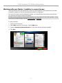
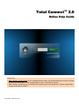
Total ConnectTM 2.0 Online Help Guide Hints for use: • When viewing in a web browser, hit F11 to toggle full screen mode. Use the bookmarks panel or table of contents to jump to the desired topic. Select the page header to return to the table of contents. • When viewing on mobile devices, use the table of contents to jump to the desired topic. Select the page header to return to the table of contents. 800-08936V4 10/15/2014 Rev. A Contents Before you start ................................................................................................................... 1 Total Connect and your web browser ................................................................................. 1 Total Connect and IP video ............................................................................................... 1 IP camera firmware updates ............................................................................................. 1 Overview of features ............................................................................................................ 2 Synchronizing data ............................................................................................................... 4 Customizing your layout........................................................................................................ 5 Information area .................................................................................................................. 5 Getting your mobile apps .................................................................................................. 5 Security module ................................................................................................................... 6 Events, Rules & Notifications module ..................................................................................... 7 Filtering events ................................................................................................................ 7 Setting up event notifications ............................................................................................ 8 Example 1 – System Event Notification ........................................................................... 8 Example 2 – Sensor Open Event Notification ................................................................... 9 Example 3 – No Disarm Event Notification .................................................................... 10 Example 4 – Video Triggered Event Notification ............................................................ 11 Example 5 – Scheduled Event Notification .................................................................... 12 Users module ..................................................................................................................... 13 Adding users .................................................................................................................. 14 Editing users .................................................................................................................. 15 Creating an event notification group and adding members ................................................. 17 Locations module ............................................................................................................... 18 Editing the location......................................................................................................... 18 Configure information services......................................................................................... 19 Edit slide show ............................................................................................................... 19 Automation module ............................................................................................................ 20 Thermostat scheduling.................................................................................................... 21 Creating an automation scene ......................................................................................... 22 Automation helpful hints ................................................................................................. 23 Video module..................................................................................................................... 24 Viewer windows ............................................................................................................. 25 Tool buttons .................................................................................................................. 27 Edit camera settings ....................................................................................................... 28 Updating the camera firmware ........................................................................................ 33 Improving video captures ................................................................................................... 34 How to best apply these guidelines .................................................................................. 34 Video troubleshooting ......................................................................................................... 36 Configuring the QuickTime player .................................................................................... 36 GPS module ....................................................................................................................... 39 Editing the module information ........................................................................................ 40 Viewing the tracking information ..................................................................................... 40 GPS tracking map icons .................................................................................................. 45 GPS low battery event messages ..................................................................................... 46 Charging the Asset Tracker battery .............................................................................. 46 Working with your Dealer / Installer to correct issues ............................................................ 47 Total Connect 2.0 Online Help Guide Before you start Total Connect and your web browser Total Connect works with all the popular web browsers. However there are some requirements based on operating system, browser and add-ons such as QuickTime and Flash. To ensure a smooth experience please check the web browser requirements. Click for web browser requirements Total Connect and IP video For those users that have video services (IP cameras), please take the time to install/configure QuickTime player. This is necessary to view streaming video. Click to configure the QuickTime player In addition, we have a special topic on how to improve video captures using your IP cameras. Click to learn more about improving video captures IP camera firmware updates As products improve the firmware for an IP camera may need to be updated. Typically these changes improve performance and response times, and may even add a minor feature. Click to learn more about updating the camera firmware –1– Total Connect 2.0 Online Help Guide Overview of features TC2 includes a lot of features and convenience items for a more connected experience with your security system. Let’s take a quick look at the features. (Note, only those features that your system supports will appear.) 5 Day Forecast – This is based on the security system’s ZIP code, and is especially useful for multiple locations that span different regions. News, Traffic, and other information (LYNX Touch L5100, L5200, L7000 only) – Optional pushed content based on the ZIP code and appears on the control display. The traffic information covers a 50 mile radius around the security system’s location. (Contact your security provider to get this optional “Information Services” feature.) Messages (LYNX Touch L5100, L5200, L7000 only) – These are security provider information messages that keep users abreast of the latest new products, features, technology upgrades, and special offers. Since there are a lot of new products and features in the pipeline this is an excellent way of staying informed. Locations module – This module shows all the systems and their locations that are available for control to the Master User. Subordinate users will only see locations they are authorized to. At each location, the modules that appear pertain only to the selected location. So if that location does not have video, the Video module will not appear. Besides the normal functions, the Location module enables you to sync panel data, configure information services and add / edit a slide show for display on the location’s security system. The “Slide Show” feature is for those security systems that support picture slide shows (such as the LYNX Touch L5100, L5200, L7000 series) and is functional only when using Wi-Fi or the internet. (Contact your security provider to get this optional “Information Services” feature.) Security module – This module enables easy control of the location’s security system. It displays detailed zone status and has zone bypass controls. Additionally it has a “keypad view” that can be used for control of more advanced features. (Not available for LYNX Plus L3000, or LYNX Touch L5000.) Events, Rules & Notifications module – Allows you to view all events (including automation events for the LYNX Touch L5100, L5200, L7000 series). You have the ability to schedule the notification of events. A “Summary” feature enables viewing and printing of all events for the location. For the LYNX Touch L5200, L7000 series scheduling has been extended to include choices for Sunrise/Sunset scheduling and also the ability to randomize a fixed schedule. Randomizing allows turning something on/off within a +/– 30 minute window. –2– Total Connect 2.0 Online Help Guide Users module – Allows you to add subordinate users and manage their profile. You can grant/deny access to various devices (automation, cameras, etc.) for each user. Further you can sync user data between the control panel and Total Connect. (Not available for LYNX Plus L3000, or LYNX Touch L5000.) Automation module (LYNX Touch L5100, L5200, L7000 series only) – This module supports Z-Wave automation devices. Using Total Connect you can control the system’s automation devices like; thermostats, lights, outlets, door locks, shades, etc. In addition you can create “scenes” to control your premises’ automation devices when leaving, entering, going on vacation, or other occasions. Video module – This module enables viewing and controlling the cameras. Up to six cameras per location are supported. You have thumbnails for each camera and each can be expanded for a more detailed view that is updated in real time. GPS module – This module is used in conjunction with the various vehicle/asset trackers. Each GPS tracking device collects location data and reports to Total Connect where information can be viewed in real time. You can track assets seeing their map location, starts, stops, path information, and historical data. Custom geofence boundaries can be setup to trigger location alerts via email. In addition for the vehicle tracker, you can set up excess speed alerts, and receive email notifications of events. Depending on the plan assigned to the asset, more information and features are available. There are two plans available: Feature Basic Enhanced Up to 20 asset trackers per location x x Low battery notifications x x “Locate Now” requests (60 per month) x x Geo-Fences (up to 8 per device) with Entry/Exit alerts x x Asset Moving / Asset Stopped information (TCAT-EB only) x x TCVT2 unplugged / restored notification x x Selectable Speed Alerts (TCVT2 and TCAT only) x 5-minute bread crumbing x Tracking Event History (90 days) x (Contact your security provider to get this optional “GPS” feature.) –3– Total Connect 2.0 Online Help Guide Synchronizing data Syncing certain features is required to assure the Total Connect data and the Security System data are the same. There a few different “Sync” functions dependent on what type of security system you have. The synchronization request button for the Locations module, Users module, and Automation module will not be processed if the keypad view (virtual keypad) was launched prior to sending the sync command. (This issue affects all systems except the L5100.) If the virtual keypad has been launched and you wish to sync, you must log out by clicking “Log Out” (do not close your browser) and log back in. You can then send the sync command. Sync requirements for the various security systems are defined below: Sync Requirements LYNX Touch L5100, L5200, L7000 Security Sync is done at the Location module. Total Connect will prompt you that a sync is required. • When a sensor is added or removed. • When a sensor name is added or changed. User Sync is done at the User module. Total Connect will prompt you that a sync is required. • When a user code is added or changed in Total Connect or at the LYNX control. The Master user in the LYNX control is assigned as the “Administrator” user in the Total Connect “User” module. This user must have the “Enable User Code Sync” check box enabled for the sync to work. Automation Sync is done at the Location module. Total Connect will prompt you that a sync is required. • When a device is included or excluded. • When a device name is added or changed. • When a “Scene” is added or changed at Total Connect. • When a “Rule” or “Schedule” is added or changed at Total Connect. • When a thermostat schedule is added or changed at Total Connect. LYNX Touch L5000 LYNX Plus L3000 Security Sync is done at the Location module. When you initiate a sync, you will be prompted for the Installer Code. • When a sensor is added or removed. • When a sensor name is added or changed. User Code management is not available for these products. Since User Synchronization is not available on these panels, any user who is disabled cannot log into Total Connect, but will still be able to use the control panel. VISTA (TC2.0 compatible) Security Sync is done at the Location module. When you initiate a sync, you will be prompted for the Installer Code. • When a sensor is added or removed. • When a sensor name is added or changed. User Sync is done at the User module. • When a user code is changed at Total Connect. The Master user in the VISTA control panel is assigned as the “Administrator” user in the Total Connect “User” module. This user must have the “Enable User Code Sync” check box enabled for the sync to work. If a user code is changed at the VISTA control panel, Total Connect will not prompt you to perform a Sync. If you feel a “Sync” is required initiate the command to update Total Connect with the latest data. –4– Total Connect 2.0 Online Help Guide Customizing your layout You can customize the look of Total Connect by rearranging the modules. Simply drag the module’s title bar to the desired position. This can be done with the module either expanded or collapsed. Left click the title bar and drag to the desired position. Information area This area provides weather and messages. This information is based on the security system’s location. Click on the weather to pull up a 5-day forecast, or click on the message envelope to read important messages. These messages are from you security system provider and relate to service calls, new products, upgrades, and special offers. Click to pause email notifications. Very convenient for when you are at the location and do not need notifications. Getting your mobile apps Honeywell mobile apps are available for your Apple, Android or BlackBerry mobile devices. Just click on Mobile Apps. –5– Total Connect 2.0 Online Help Guide Security module You can toggle between a quick look at your security system’s status, or bring up a keypad to control your security system. Used to clear troubles. Click to toggle between “Status” or “ Keypad” view. Security system “Status” view. Click to toggle back to “Status” view. This area provides detailed zone information. You can select from filters on the left such as; Alarms, Troubles, etc., to just view specific zone conditions. • Zones can be bypassed and troubles cleared. • Zones can have multiple faults. • Works like your security system’s keypad. Not available for the LYNX Plus L3000 and the LYNX Touch L5000. –6– Total Connect 2.0 Online Help Guide Events, Rules & Notifications module This enables you to view events that result from your; security system, rules & notifications, IP video cameras, and automation devices (Z-Wave devices). Security events are stored for 90 days, and Video events are stored for 90 days or a maximum of approximately 100 MB. In either case, older events are deleted to make room for new events. Click to see the details of all your scenarios. Search Filter. Click to set up event notifications. Toggles between Live Events, and Admin Logs. Click to play video event. Enables attaching a note to the event. Recent Live events. Enables locking the event to prevent deletion. Click to hide the event. Sample Summary Screen: Filtering events After clicking the Search icon, the following choices appear. Check to show all hidden events. Search Filter. –7– Total Connect 2.0 Online Help Guide Setting up event notifications This is where you choose which events will be reported to a particular user group. Before setting up event notifications for “Sensor Open” or “Sensor Close” conditions, ensure a session with the security system’s Control Panel is not active. The best way to assure this is to log-off of Total Connect, then log in again to setup the event notifications. Take the time to explore each notification category and become familiar with the event types that can trigger notifications. Event categories may have expandable sub-categories. Categories that are not supported by your security system will not appear. Further, the Admin category will not appear if the user does not have Admin rights. For the LYNX Touch L5200, L7000 series scheduling has been extended to include choices for Sunrise/Sunset scheduling and also the ability to randomize a fixed schedule. Randomizing allows turning something on/off within a +/– 30 minute window. Example 1 – System Event Notification In the example below; a Security system event (AC Loss) was chosen to notify the Default Group of users. When an AC Loss occurs, each member of the Default Group will be notified. 1. On the Events, Rules & Notifications bar, click the Setup icon. 2. You start by picking from the event categories; Security, Video, Automation, GPS, Admin, Schedules, or Emergency Alerts. For this example, select the Security icon. Event Categories: • Security • Video • Automation • GPS • Admin • Schedules • Emergency Alerts 3. From the Security > System event category, choose the event (AC Loss) to be notified of. 4. At the right, click Notification. The notification info window appears. 5. Enter a Subject name for the email notification. Then from the Send To drop-down menu, select the user group to notify. (Ensure the Enabled box is checked.) To add another user group to be notified, click Notification again and repeat. 6. Repeat for all events that require notifications. 7. Click Save. The “Default Group” will be notified whenever an AC Loss condition occurs. –8– Total Connect 2.0 Online Help Guide Example 2 – Sensor Open Event Notification In the example below; a Sensor Open condition (Flood) was chosen to notify the Default Group of users. This type of notification might be used when you want to be notified when a security cabinet, special room, flood or other sensed condition within the premises occurs. When the Sensor Open condition occurs, each member of the Default Group will be notified. 1. On the Events, Rules & Notifications bar, click the Setup icon. 2. You start by picking from the event categories; for this example, select the Security icon. 3. From the Security > Sensor Open/Close event category, choose the event (Flood) to be notified of. 4. At the right, click Notification. The notification info window appears. 5. Enter a Subject name for the email notification. Then from the Send To drop-down menu, select the user group to notify. (Ensure the Enabled box is checked.) Since this is a Flood condition, you would always want to be notified, therefore at the Sched / State drop-down field select Always. To add another user group to be notified, click Notification again and repeat. 6. Repeat for all events that require notifications. 7. Click Save. The “Default Group” will be notified whenever a Flood condition occurs. –9– Total Connect 2.0 Online Help Guide Example 3 – No Disarm Event Notification In the example below; a No Disarm event was chosen to notify the Default Group of users. This type of notification might be used when you want to be notified when a child is due home from school by a certain time; and did not arrive at the home. When the No Disarm condition occurs (by the specified time), each member of the Default Group will be notified. 1. On the Events, Rules & Notifications bar, click the Setup icon. 2. You start by picking from the event categories; for this example, select the Security icon. 3. From the Security > Arming event category, choose the event (Disarmed) to be notified of. 4. At the right, click Notification. The notification info window appears. 5. Enter a Subject name for the email notification. Then from the Send To drop-down menu, select the user group to notify. (Ensure the Enabled box is checked.) Since you want to be notified if this event DOES NOT occur, ensure the Notify me when this event does not occur is selected. 6. Since this is a time dependent event, click the Sched / State Edit button to setup the schedule. 7. Set the schedule parameters, then click Save. 8. The “Default Group” will be notified whenever a Disarmed condition DOES NOT occur by 4:30 pm on any weekday. – 10 – Total Connect 2.0 Online Help Guide Example 4 – Video Triggered Event Notification In the example below; a video camera will detect motion when the security system is armed away. Any detected motion will be used to trigger a notification to the Default Group of users. This type of notification might be used when you want to be notified if there is motion in a store after hours. When video motion occurs, each member of the Default Group will be notified. NOTE: For configuring the camera become familiar with the “Edit camera settings” topic, and particularly the information on “Event Detection Areas” as needed. 1. On the Events, Rules & Notifications bar, click the Setup icon. 2. You start by picking from the event categories; for this example, select the Video icon. 3. At the left, choose the event category Video > Video Events > Camera 3. 4. From the Sched / State drop-down field, choose Armed Away. 5. The “Default Group” will be notified whenever camera 3 detects motion when the security system is Armed Away. – 11 – Total Connect 2.0 Online Help Guide Example 5 – Scheduled Event Notification In the example below; when the High Value Tool Room is opened during the night shift, a notification will be sent to the Default Group of users. This type of notification might be used when you want to be notified of an event that might occur during a certain time schedule when the security system is disarmed. When this event occurs (during the scheduled time), each member of the Default Group will be notified. 1. On the Events, Rules & Notifications bar, click the Setup icon. 2. You start by picking from the event categories; for this example, select the Security icon. 3. From the Security > Sensor Open/Close event category, choose event Sensor Open, then HV Tool Room. 4. At the right, click Notification. The notification info window appears. 5. Since this is a time dependent event, click the Sched / State Edit button to setup the schedule. Click Add Schedule. The schedule window appears. – 12 – Total Connect 2.0 Online Help Guide 6. Enter a Name for the schedule (such as HV Tool Room). Then set the schedule parameters and click Save. 7. Repeat steps 2 thru 4. 8. Enter a Subject name for the email notification. Then from the Send To drop-down menu, select the user group to notify. (Ensure the Enabled box is checked.) 9. From the Sched/State drop-down menu, select the schedule (i.e., HV Tool Room) you just created then click Save. The “Default Group” will be notified whenever the High Value Tool Room is opened on the night shift. Users module Create an event notification group and add members. Shows users associated with this Total Connect account. Add a new user. To edit a user, hover over the user and click Edit. Button toggles between This Location Only and All Locations. Click to synchronize user data between the control panel and Total Connect. Note: The LYNX Plus L3000 and the LYNX Touch L5000 do not support synchronizing users. Green = User is enabled. Red = User is disabled. Privilege level Privilege Level Master User, owner of the account, and has all rights. Can view “Admin Logs”. Administrator, can create new users, sync users, and disable users. (Cannot disable the Master User.) If enabled by the Master User, can also manage user codes for others. System Administrator, can create and edit notifications. Alert, a reminder to validate your email address. – 13 – Total Connect 2.0 Online Help Guide Adding users Adding users is easy, just follow these steps. 1. At the Users module, click Add User. 2. A selection screen appears. 3. Choose the type of user you want to create, then click its icon. The appropriate user dialog screen appears. 4. Depending on the type of user chosen the fields in the dialog screen will vary. For a description of what those fields mean, refer to the next topic. 5. Upon completion, click Save. – 14 – Total Connect 2.0 Online Help Guide Editing users Notes: User Name: 6-80 character length (not case sensitive) Password: 6-32 character length (case sensitive) Valid Entries: 0-9, A-Z and ? ! @ # $ % ^ * - _ = + . 4. Enter the control Panel User number assigned for the user. This is for email and event logs when the system is armed / disarmed and will display the user’s first and last name. If the Enable User Code Sync is checked, the “Panel User” field will be grayed out and the “Panel User” number cannot be changed. 5. Enter the 4-digit User Code, so this user will not be prompted for it when arming / disarming the security system. Check the desired boxes to grant access to devices. If master user, refer to the Enable User Code Sync Rules on the next page. 1. Edit user information. 2. Check to give user rights. Refer to definitions that follow. 3. Add email and SMS notification information. Refer to definitions that follow. 6. Click Save. User Rights Administrator Admin rights grant the ability to add and control other users as well as to configure and edit notifications. Security Professional Access Allows the security professional one time access to the users Total Connect account with full access to edit settings and help troubleshoot problems. (User codes cannot be changed, and video cannot be viewed.) Once access is granted the Master user will receive an email. The granted access will expire after 60 minutes. Enable User Code Management See detailed rules below. Allows you to manage panel users from Total Connect. Note, the LYNX Touch L5000, and L3000 do not allow managing users. Prompt for user code When checked the user must enter their panel User Code. Display User Codes When checked the Panel User number and User Code are displayed. – 15 – Total Connect 2.0 Online Help Guide Enable User Code Management Only the Master User that is assigned to the control panel can synchronize user codes. When synchronizing users for the first time, the Master User Code in the Total Connect database must match the Master User Code programmed in the security system’s control panel. When the Master User changes a user code and performs a sync, a successful change can be verified by checking the Events Rules & Notifications (Admin Logs) for a synchronization event. LYNX Touch L5100, L5200, L7000 If the Master User is enabled for User Code Sync, any user they disable cannot log into Total Connect, and will be deleted from the control panel. If the Master User is NOT enabled for User Code Sync, any user they disable cannot log into Total Connect, but will be able to use the control panel. LYNX Touch L5000 LYNX Plus L3000 If the Master User is NOT enabled for User Code Sync, any user they disable cannot log into Total Connect, but will be able to use the control panel. VISTA (TC2.0 compatible) If the Master User is enabled for User Code Sync, any user they disable cannot log into Total Connect, and will be deleted from the control panel. If the Master User is NOT enabled for User Code Sync, any user they disable cannot log into Total Connect, but will be able to use the control panel. Email Definitions SMS (short message service) Limited to under 160 characters, this is the most basic concise message. It arrives along with the users other text messages. This is a good choice for users that just want the most brief notification, and work extensively with text messaging. Text Email A very basic email that does not contain any formatting, or graphics. It may contain an internet link. This is a good choice for basic cell phones that support email. HTML Email A feature rich email that exhibits text formatting, graphics and anything else that may be contained on a web page. This is a good choice for smartphones where the user prefers a rich HTML presentation. Text w/ Attachment A very basic email that does not contain any formatting, or graphics. It may contain an internet link, and may contain an attachment. This is a good choice for smartphones where the user prefers brief condensed emails but may want to view attachments. HTML w/ Attachment A feature rich email that exhibits text formatting, graphics and anything else that my be contained on a web page. This choice allows attachments. This is a good choice for smartphones where the user prefers a rich HTML presentation with the ability to view attachments. – 16 – Total Connect 2.0 Online Help Guide Creating an event notification group and adding members This is where you configure which notifications are sent to each user group. Some important points are: • • • Each member must be assigned to a group (a group can contain one or more members). Also the master user is a predefined group (default group). Within a particular group you can choose ALL members, NO members, or only certain members. The notification list can be enabled or disabled as needed. 1. On the module bar, click User Groups. 2. Select from an existing group or click Add Group. 3. Enter a Name for the group, then check Enable This List. 4. Select which group members are to be notified. 5. Click Save. Select which group members are to be notified. Select All Select NONE Send Test Email to Group – 17 – Total Connect 2.0 Online Help Guide Locations module This is where you can edit information on a particular location. Shows the systems associated with the account. Click to synchronize location data between the panel and Total Connect. To edit a location, hover over the name and click Edit. Editing the location 3. Choose the location’s time zone. 2. Enter a location name. The time zone only applies to event logs and email notifications. It does not effect the control panel time. 1. Click here to choose a picture. Used to sync Total Connect data and control panel data. Configure Information Services. Edit Slide Show. 4. Click Save. – 18 – Total Connect 2.0 Online Help Guide Configure information services This feature allows you to add weather information to the Total Connect information area, and content such as weather, news, traffic, and notes to the LYNX Touch L5100, L5200, L7000 display. Clicking here brings up icons that allow you to reorder how the push content appears on the LYNX Touch L5100, L5200, L7000 screen. Edit slide show (Contact your security provider to get this optional “Information Services” feature.) This tool supports the LYNX Touch L5100, L5200, L7000 control slide show feature. It allows you to add, crop, and delete photos. Pictures are cropped to 480 x 272 pixels. 1. Click to add a picture from your PC. 2. Click “Choose Photo” and navigate to the file on your PC. 3. Position and resize the crop box. • Each file must be either .JPG or .PNG and under 2MB. • Up to 13MB of space is available. • The LYNX Touch controls must be communicating using Wi-Fi. – 19 – 4. Click Save. Total Connect 2.0 Online Help Guide Automation module This module is for those security systems that support Z-Wave automation devices. Security systems such as the LYNX Touch L5100, L5200, L7000 support Z-Wave automation devices. Automation allows control of door locks, lights, outlets, shades, and thermostats. In addition to manual control of these Z-Wave devices through Total Connect you can create a “Scene” that would control a group of ZWave automation devices when a specific condition occurs. (Control of automation devices is restricted to users that are granted permission. See the topic “Users” for more information.) Conditions such as arming and disarming a security system can trigger a “Scene” to be run. Let’s look at the Automation module. Toggles between Quick Control and Full Control mode. Low Battery Warning Thermostat control, the features displayed depend on the model. Automation devices, you can filter what is viewed by using the filters. Here is where you create or edit Scenes. For certain devices you can select a custom icon. Scheduling, on this thermostat you can schedule temperature changes. In the next topics we will explore Thermostat scheduling and creating an Automation Scene. Note, that whenever you save a created or edited a scene you will receive a temporary pop-up reminder to synchronize your panel. This will send the new scene information to the control panel. After getting familiar with the Automation module, please read the “Automation helpful hints” subtopic later in this document. – 20 – Total Connect 2.0 Online Help Guide Thermostat scheduling 1. Click the clock icon to open the thermostat scheduling. 2. The scheduling window appears. If the temperature falls outside the threshold limits, an email notification is sent. (Needs to be setup, see the “Setting up event notifications” topic.) Drag the slide buttons to set the time. Click the slide button to pop up a temperature setting box. In this example since Week Days was selected, your settings will apply to all the highlighted days. Select the days of the week to set. Another choice is to just load the “Energy Star Defaults” for your thermostat. This appears when there are multiple thermostats. It enables you to duplicate the schedule of the first thermostat to other units. With the momentary “Heat Set Points” button depressed, the temperatures are displayed. – 21 – Click and hold any of these momentary buttons to display specific information. Total Connect 2.0 Online Help Guide Creating an automation scene Here we will use the Automation module to create a simple scene to control your automation devices during a vacation. In this scene you want the following scenario to take place when you leave the premises for a vacation: • • • • • • When you leave, the automatic front and rear door locks will lock. The living room light will be dimmed to 80%. The kitchen light will be dimmed to 80%. The porch light will be dimmed to about 25%. The electric porch heater will be set to off. The main thermostat will be set back to 62 degrees to save energy. To create the Vacation scene: 1. Click Create New. Then in the Scene Name field, enter the name “Vacation”, then choose an icon. 2. In the device area, ensure the ALL filter is activated so you can see every device. Use the scroll left and right arrows if necessary to find the automation device. 3. Since we want the front and rear door locks in the locked mode, check the box by each lock to include it in this scene. Click the front and rear door lock icons to attain the LOCKED state. 4. Find the living room light device, and check the box to include it in the scene. Set the dimmer slide to about 80%. Repeat this for the kitchen light, and the porch light, using the dimmer slide to the desired illumination level. 5. Find the porch heater and check the box to include it in the scene. Click the icon to attain the OFF state. 6. Look at each device and ensure only those devices to be included in this scene have their box checked. 7. Set the thermostat to 62 degrees and click the hold button. 8. Save the scene. 9. Click the green Run button to verify the automation devices action. Make any changes as necessary. Using the scene: When you leave for vacation you would arm the security system in the normal manner. Then after leaving the premises use your smartphone or other device to log into Total Connect. At the Automation module, select the “Vacation” scene and click run. – 22 – Total Connect 2.0 Online Help Guide Automation helpful hints There are many configuration options in the Automation module, some can be configured at the LYNX Touch control, but it is much easier to perform all these tasks from Total Connect. Manual control of your automation devices is easily done from the automation module. The same is true for creating and editing simple scenes. However there are times when a more detailed scene is desired. As you get familiar with creating and running simple scenes, you will be ready to create more detailed scenes. Below are a collection of functions that more advanced users should be aware of. General: • • Only those features offered by the Z-Wave device will appear. When necessary, left and right scroll arrow buttons will appear to view more devices. Thermostat: • • • • • Thermostat name is limited to 13 characters. Thermostat and Fan mode buttons will toggle through their different modes. If the mode button is held a pop-up list of possible modes will appear. When auto mode is selected, Dual set points will appear. When a thermostat set point is changed, the thermostat will stay at that temperature until the next set point time. If the Hold button is selected, the thermostat will stay at that temperature until either the hold button is pressed again, or any other thermostat property is changed. In that case the Hold button will deselect. Locks, Switches, Dimmers, and Outlets: • • • These devices can be dragged to the desired order. An “X” will appear for any device that is not connected. If you have a Z-Wave door lock, a jammed condition will be sensed and will appear in the “Events, Rules & Notifications” module. This condition can be configured as an email notification. Scenes: • • • You can create up to 20 scenes with a total limit of 47 devices. Each scene is limited to 4 locks, 3 thermostats, and 40 lights/switches. (Actual limits are determined by the LYNX Touch control.) After creating a new scene, use the green run button to test the scene. When in the “Quick Control” mode (button on the Automation module), the you will see a series of scenes. Just click on the scene to run it. – 23 – Total Connect 2.0 Online Help Guide Video module Total Connect lets you monitor up to six cameras, providing thumbnail images for each one (Thumbnails are updated every 10 to 20 seconds). In turn, each thumbnail image can be double clicked to open a resizable real-time streaming video viewer window. Enables you to set various parameters for this camera. Refer to the topic “Edit Camera Settings”. Firmware update notification. Refer to the topic “Updating the camera firmware”. Wireless camera signal strength indicator. Wired camera. The various cameras each have different features that can be controlled. When a particular camera is selected, only the Tool buttons for that model camera will appear. The table below highlights the features of each internet camera model: Camera Features iPCAM-WI Camera • wired or wireless • fixed lens • video motion detection iPCAM-WI2 Camera iPCAM-WI2B • wired or wireless • sleek design • fixed lens • comes in black, or white • video motion detection iPCAM-PT / iPCAMPT2 Camera iPCAM-WO Camera • wired or wireless • PIR motion detection • fixed lens • pan and tilt with presets • video motion detection • aux lighting • wired or wireless • PIR motion detection • fixed lens • outdoor use • video motion detection iPCAM-WL • wired or wireless • fixed lens • automatic normal/low-light lens function (0 Lux level) • video motion detection ACU Wireless Analog Converter Unit • Allows any camera that outputs NTSC video to be used with Total Connect. • provides a video output for a local NTSC video monitor Refer to the topics that follow for details on the viewer windows, tool buttons and how to set your camera preferences. – 24 – Total Connect 2.0 Online Help Guide Viewer windows Working from the thumbnails you can open one or more viewer windows by double clicking the thumbnail. Each viewer window; • • • displays video in real time. can be resized, and arranged by dragging. displays the tool buttons based on the camera features. For information on the tool icons, refer to the “Tool buttons” topic. About Network Bandwidth . . . Since the IP cameras are network devices, they depend on the network’s ability to transfer data. This ability is referred to as bandwidth. Although you can stream up to 6 cameras you are limited by the network bandwidth supplied by your internet provider. In addition, be aware your actual network bandwidth will decrease depending on your local network traffic and transport servers. There are three measurements that affect the quality of network service: Upload Speed – The amount of data that can be transferred from the transmitting premises (where the cameras are located) in a period of time. This is measured in bits per second. Download Speed – The amount of data that can be transferred from the receiving premises (where the Total Connect application is running) in a period of time. This is measured in bits per second. Ping Time – Internet transfers do not go directly from the source to the destination server, instead they hop from available server to available server to reach the destination server. With each hop there is a response lag referred to as “Ping Time.” Depending on the number of hops, this lag can add up. To attain maximum video quality and frame rate from your IP camera it requires a transfer speed of 1.5 Mbps for both Upload and Download paths. Therefore to achieve this for six IP cameras it requires 9 Mbps for both Upload and Download paths. Many internet providers easily exceed this bandwidth. If the necessary bandwidth is not available, the resolution and frame rate will decrease. If this situation occurs, consider having less viewer windows open. That will free up bandwidth for the important IP cameras you want to monitor. Below are some examples of viewer windows. Pan/Tilt Camera, initial view Use the Enlarge button to bring up a larger dedicated viewing window. – 25 – Total Connect 2.0 Online Help Guide Pan/Tilt Camera, expanded to full screen The tool buttons displayed are based on the camera features. • You may use the arrow buttons to position a PT (pan & tilt) camera. • Use single clicks and allow time for the camera to attain the new position. • Use the center Home button to command the camera to its home position. • Refer to the detailed description in the "Tool buttons" topic. – 26 – Total Connect 2.0 Online Help Guide Tool buttons Button Function How the camera's "Home" position is determined. • If no video detection areas have been set up, the camera's home position is centered in its vertical and horizontal axis. • If a video detection area has been set up, that view now becomes the home position. • When a camera has been moved to other than the home position, after 5 minutes of no movement the camera will always return to the home position. arrow buttons – Click to incrementally position the camera in a vertical or horizontal direction. center home button – Click to drive the camera to its home position. preset buttons 1, 2, 3, 4 – These buttons are used to quickly drive the camera to a preset watch area. (Up to 4 preset watch areas can be set.) Just "single-click" the button to go to the preset watch area. To set a preset watch area, use the arrow buttons to drive the camera to the desired area. Then press and hold the desired 1, 2, 3, or 4 button for about 3-seconds. A checkmark will briefly appear to confirm the preset is saved. movie camera – Used to manually capture video clips. When clicked, a 10 second video clip is captured, based on the pre-capture and post-capture settings stored in the camera. The video clip will be stored as an event, and may trigger an email notification if desired. (Refer to the "Edit camera settings" topic.) Note, if a scheduled period has been setup for video motion detection, this feature is restricted to the scheduled period. If no schedule has be setup, there is no restriction (operates 24/7). still camera – Used to manually capture still pictures. You will be prompted to save the picture if desired. Note: The still camera feature is currently only accessible using the mobile apps. light – Used to toggle on or off the camera's auxiliary lighting LEDs. Depending on the ambient low light conditions, the auxiliary LED lighting can improve video quality up to 15 feet. auto pan – Causes the camera to swing through its entire horizontal range. At the end of the panning motion, the camera will return to the starting position. After 5 minutes of no movement the camera will always return to the home position. enlarge – Used to toggle the viewer window between full screen and previous view. stop / play – When clicked, this button toggles between stopping and starting the live video stream. When stopped, the video image is replaced by a blank screen. Note, if you inadvertently click on the live video screen, the video may go blank. You can use this button to restart the live video. – 27 – Total Connect 2.0 Online Help Guide Edit camera settings Note, the settings for each camera are configured separately. On each camera preview window there is a Tool icon in the lower right corner, click this icon to configure the camera. It is important to know that configuration settings are stored in the camera and are retrieved when a video session is opened. To understand the various configuration settings we will look at the settings for a typical camera. Refer to the screen shots that follow to understand how to configure each camera settings. Most settings use drop-down menus or check boxes. Edit Camera Settings Name and Date/Time You can assign the camera a descriptive name. Up to 15 characters may be used. The new name will appear when the next video session is initiated. You can also set your date and time preferences. Event Capture / Notification This screen enables you to choose what IP camera feature will be used to detect motion, and to specify the video capture window that results when motion is detected. It allows you to tailor the timing of the video capture in respect to when motion is detected. Some cameras have additional features (such as White Light LED) that you can activate here. All of our IP cameras utilize video analytics to detect motion. Some cameras also have a PIR (Passive Infra Red) detector that may be used to detect motion. Note: You must choose only one method of motion detection. PIR motion detection is based on sensing body heat via multiple beams. When the detected heat signature breaks the beams in sequence, motion is detected. It has a range of about 15 feet (4.5m) and does not require ambient light to detect motion. Video analytics detects motion by comparing sequential video frames for change. In many situations, video analytics is a superior method of detection since it can be configured to avoid areas that may have movement that would falsely detect motion. Additionally range is not a factor since motion detection is based on changes to the video frame. – 28 – Total Connect 2.0 Online Help Guide Attachment Type – If you want an email notification, choose between sending a Video Clip or Snapshot attachment. Note, regardless of the choice, a video clip will always be stored in the event history. Pre-Capture and Post Capture Length – These two settings determine the beginning and end of the 10 second period that is captured when motion is detected. For video a 10 second clip is captured, and for snapshots a series of 10 are captured. Interval – Choose from 1 to 15 minutes before the next video motion can be captured. This setting helps reduce excessive notifications. PIR, Motion, Capture, White LED camera options – This enables you to set which Triggers will be used to cause certain actions. Depending on the camera type, features that are not supported will be grayed out. Triggers can be from a security system control panel input, the camera’s PIR detector, or video motion. One or more may be selected. 1. Choose the triggered input(s) that will capture video: • PIR – Triggered by the camera's PIR sensor. Will trigger on movement within the PIR sensor view. There are no masking, sensitivity levels or adjustments. DO NOT choose if Motion detection is going to be used. • Motion – Triggered by video analytics within four user defined “Event Detection Areas”. Motion is determined by comparing current and previous video frames. DO NOT choose if PIR detection is going to be used. 2. Determine what action results from the triggered input: • Capture – The video or snap shot is stored in the Event History and can be sent as an email notification if desired. • White Light LED – The camera's white light LEDs turn on for the 10 second video motion capture period. (This works only when the room is dark.) – 29 – Total Connect 2.0 Online Help Guide Event Schedule – This allows setting schedules that define when a motion event can be detected. Schedules may be deleted by clicking the "X" adjacent to the schedule. After the camera's schedule is set up, click Save. Event Detection Areas – This allows setting up to 4 detection areas where video motion can be detected and the Activity Threshold can be adjusted. When an area is activated by checking the box, a transparent colored Detection Area will appear on the screen. You can drag and resize the box as desired. Click Done when all the areas are configured. Motion detected in any area will trigger a video event and store a video clip or series of snapshots. A lower activity threshold value will trigger clips more readily. NOTE: After setting up the detection areas, go to the topic “Setting up event notifications” and ensure all the desired notifications are enabled. Also refer to the next topic “Improving video captures” to learn how to get optimum capture results. – 30 – Total Connect 2.0 Online Help Guide Other Features – This allows setting various camera parameters that may improve the image quality. • White Balance, Brightness, Sharpness – Enables adjusting the video parameters as desired. • Ceiling Mount – For cameras that are ceiling mounted, check the Ceiling Mount box to invert the image. • Pan/Tilt Speed – Allows choosing the camera panning speed. Note, a slower speed will give clearer video. • Status LED Operation – Uncheck this box to turn off the camera's status LEDs for stealth operation. Although the camera will appear as not operating, all functions are working. Camera Information – This information is for Technical Support use only, and is not intended as a substitute for network theory. In the descriptions below, the item in red is used by Technical Support to determine the Wi-Fi quality. Camera Data Camera Type Identifies the camera model number. Firmware Version Often referred to as “Subnet Mask”, this number indicates the maximum number of IP addresses that can be hosted by the router. – 31 – Total Connect 2.0 Online Help Guide Network Data IP Address IP address of the router or Honeywell’s WAP-PLUS. Network Mask Often referred to as “Subnet Mask”, this number indicates the maximum number of IP addresses that can be hosted by the router. Gateway IP address of the modem (or gateway router) that the router communicates with. DNS Server 1 Primary Domain Name Server used by the router. DNS Server 2 Secondary Domain Name Server used by the router. DHCP Indicates if the router is using DHCP (Dynamic Host Control Protocol) to assign IP addresses to the devices. Wireless Status SSID This is the broadcast name of the wireless router or Honeywell’s WAP-PLUS. It helps the user to identify the correct router. Channel Indicates the wireless channel number the wireless router is using to communicate with the IP device. Base Station ID This is the binary number that represents the SSID (see above). Wi-Fi Signal Strength This indicates the Wi-Fi signal strength for the IP camera. Specifically the relative signal strength between the IP device and the wireless router or Honeywell’s WAP-PLUS. For installations where Honeywell’s WREX Wi-Fi Extender is used, it indicates the relative signal strength between the IP device and the WREX. – 32 – Total Connect 2.0 Online Help Guide Updating the camera firmware If your camera is not running the latest firmware an Update icon will appear. Update icon Tool icon 1. Click on the Tool icon in the lower left corner. 2. The Firmware update window appears. 3. Click the Update button. A confirmation message appears. Click OK to the confirmation message to proceed. 4. During the firmware update process the video image will be replaced with a tool image. You can continue using other cameras. When the firmware update completes, normal operation for that camera is restored. – 33 – Total Connect 2.0 Online Help Guide Improving video captures All of our IP cameras utilize video analytics to detect motion. Some cameras also have a PIR (Passive Infra Red) detector that may be used to detect motion. PIR motion detection is based on sensing body heat via multiple beams. When the detected heat signature breaks the beams in sequence, motion is detected. It has a range of about 15 feet (4.5m) and does not require ambient light to detect motion. Video analytics detects motion by comparing sequential video frames for change. In many situations, video analytics is a superior method of detection since it can be configured to avoid areas that may have movement that would falsely detect motion. Additionally range is not a factor since motion detection is based on changes to the video frame. The video analytics utilize up to four detection areas. Each detection area can be positioned and resized in the video frame to only look at areas of concern and to avoid areas that would result in false motion detection. When using video analytics, use the guidelines below to properly setup the camera to detect motion. Video m otion to avoid • Lighting that is subject to rapid changes will cause unwanted motion detection. Examples are; rapid changes from cycling interior lights, or external lighting that changes due to moving clouds, moving foliage, and weather conditions. • People or cars that normally pass by a window, door or sidewalk. • Blowing plants or flags. • In commercial situations, non intrusion areas where people are expected to be. W hen the scene has poor lighting Poor lighting or low contrast scenes will never produce reliable motion detection. If the camera can’t see the people, the video analytics will not detect any motion. Improve the scene by: • Adding more lights. This is especially helpful in outdoor scenes, such as the backyard, or that dimly lit pathway or porch. • Distribute the lighting so as to reduce shadows. • Using brighter lights. Configure the capture zones for optim um m otion detection • Consider if the camera is correctly aimed to concentrate on the area that needs protection, and avoids those areas that would not improve protection. • Look at the image and identify portions of the image that would keenly capture motion that results from intrusion. Position the detection areas to overlay those image portions. • Keep the detection areas as small as possible to eliminate looking at video that may result in false cap- tures. • Take another look and readjust the position and size of the detection area as necessary. • Test and fine tune the Activity Threshold setting for each detection area. How to best apply these guidelines By using the guidelines above to Configure the Detection Areas, then Adjust the Activity Threshold we can optimize camera’s detection. Let’s take a look at some sample configurations. – 34 – Total Connect 2.0 Online Help Guide Configure the Detection Areas By using smaller detection areas you get better motion detection with less false triggers. Let’s take a look at some sample configurations. The activity threshold can be adjusted for each detection area. The default setting is mid position and that will work well for most detections. However by taking the time to test the scene and fine tune this setting, a higher success rate of detections can be achieved. Adjust the Activity Threshold REMEMBER - - A lower activity threshold value will cause the camera to trigger more readily. In the picture above, we avoid outdoor lighting and focus on three capture areas; the stairway, far hallway, and near hallway. This room has two walls of outdoor lighting that can cause problems. In this case, three detection areas were used. One area covers possible intrusion from the windows, another covers the stairs, and lastly one covers the hall with adjacent room. This entryway is surrounded by side glass panes that are subject to external lighting changes. Further, shadows caused by delivery people and mail people may trigger motion. In this case we chose one simple detection area that would trigger when the doors are opened. – 35 – By following these guidelines, a high degree of valid motion detections can be attained. However, because of the many variables that can cause unwanted motion detection there is no way to eliminate all undesired motion detection. Total Connect 2.0 Online Help Guide Video troubleshooting If you are experiencing any difficulty with your video, please refer to the information below. SYMPTOM – The thumbnails are working but there is no streaming video. Cause: Your must have Apple QuickTime installed on your PC and updated to the latest version. Perform the following corrective steps. If you do not already have QuickTime Player installed please download and install it. http://www.apple.com/quicktime/download/ After the installation is completed and the PC has been rebooted, configure the player. Configuring the QuickTime player 1. Open the player. Typically navigate Start > Programs > QuickTime > QuickTime Player. 2. From the Edit pull-down menu, navigate Preferences > QuickTime Preferences. The Preferences window appears. 3. Select the Advanced tab. Then using the Transport Setup drop-down box, select Custom. 4. Ensure the Transport Protocol is set to HTTP, and the Port ID is set to 80. 5. Click OK, then click Apply. Click OK to close. – 36 – Total Connect 2.0 Online Help Guide SYMPTOM – Camera is not triggering on motion, or triggers too often. Cause: A detection method must be selected or modified. Either PIR or Motion must be selected. If Motion is selected, then the camera analytics need to be adjusted. Perform the following corrective steps. 1. Log into Total Connect and open the “Video”, then for the appropriate camera select the Tool icon. Tool icon 2. Check the Event Capture / Notification Setting, Event Schedule, and Event Detection Areas settings. You may have to adjust the Pre-Capture and Post Capture length settings. Use a test subject walking across the field to help in finding the best video capture parameters. Ensure that either PIR or Motion is selected. DO NOT select both. PIR detection – works by using input from the camera’s built-in PIR sensor. This is not adjustable. Motion detection – works by analyzing frame-to-frame video differences. This is adjustable by clicking the EVENT DETECTION AREAS button, then adjusting the Activity Threshold for each detection area. Further attention should be given to the detection area size. See the guidelines below for setting the video analytics. – 37 – Total Connect 2.0 Online Help Guide If you have an Event Schedule set up, be aware that triggering will only occur within the scheduled time frame. In the Event Notification settings, ensure Motion is selected and PIR is NOT selected, then return to Event Detection Areas. The following screen appears to enable adjusting the Activity Threshold for each area. Using the information below, make the adjustments, then click Done. • Adjusting the Activity Threshold to the side will increase the amount of activity needed to trigger the camera. • Select the position and size of each detection area carefully so as to exclude areas that may cause un- necessary triggering. Consider positioning tightly on the area, or a pathway that leads to that area. – 38 – Total Connect 2.0 Online Help Guide • For indoor scenes, note that fans, curtains, changing light sources, shadows, and reflections off of other objects may produce false triggering. • Consider repositioning the camera. The best detection is when motion is across the screen. • When possible set the camera angle, and detection area height to avoid pets. • For outdoor scenes, note that moving plants, and shadows may produce false triggering. NOTE: In order for any change to take place you must click DONE to save the information for that camera. GPS module GPS tracking modules provide location and other information for various assets (see listing below). The GPS tracking module collects location data and reports to Total Connect where information can be viewed in real time. You can track assets seeing their map location, starts, stops, path information, and historical data. For vehicle trackers, custom geofence boundaries can be setup and be used to trigger location alerts via email. Additionally you can set up excess speed alerts and receive email notifications of those events. Depending on the plan assigned to the asset, more information and features are available. For plan information click here. GPS tracking modules TCVT2 Vehicle Tracker Features • For ODBI II compliant vehicles. • Unplugged tracker sensing. • Custom geofences. • Excess speed alerts. This device uses a certain amount of current from the battery even when the vehicle is turned OFF. Care should be taken in using the device in vehicles that have old or weak batteries, or that may go extended periods without being started. TCAT Asset Tracker • For fixed and movable assets. Also for vehicles that are not ODBI II compliant. • Low profile asset tracker that is water, vibration and shock re- sistant. • Battery backup. TCAT-EB Asset Tracker • For fixed and movable assets. • Robust asset tracker that is water, vibration and shock resistant. • Extended battery backup. The following information depicts operation for a Vehicle Tracker; Asset Trackers operate in the same manner. Of course if the asset does not have an engine, those features showing ON/OFF status will not appear. – 39 – Total Connect 2.0 Online Help Guide Editing the module information 1. To edit the vehicle information, hover over the vehicle and click Edit. 2. The edit window appears. In the Name field, enter a descriptive name for the vehicle. These icons determine what will appear on the GPS Tracking window. Camera icon allows you to select a picture on your PC. 3. Then use the camera icon to pick a photo from your PC, or pick from one of the stock vehicle pictures by clicking the Icons button and select the color by clicking the Color button. Then click Save. If you select a picture from your PC, the file must be in .JPG, or .PNG format and under 2MB in size. Viewing the tracking information 1. To view the vehicle tracking information, click any vehicle to open a separate GPS Tracking window. An “Unknown” state means the device has not communicated its status. This can be caused by; a disconnect condition, lack of power, asset is sheltered or covered thereby obstructing communications. 2. A blank GPS Tracking window appears along with your vehicles. – 40 – Total Connect 2.0 Online Help Guide Click on the vehicle you want to track. 3. Clicking on the vehicle opens a window specifically for the selected vehicle. Tool icons can be toggled to minimize. 4. The right-pane window has tool icons for the selected vehicle. These Tool icons are described below. History Opens a calendar pane that allows you to retrieve historical tracking data. Historical data is stored for 90 days. – 41 – Total Connect 2.0 Online Help Guide You can enter the desired historical day (yyyy-mm-dd format) in the field or use the calendar below to select the day. Clicking on a particular day populates the above info field. Click Set Date to open the historical data. The selected historical data will now appear on the map’s top title along with the date and vehicle. After reviewing historical date remember to return to the current date. Devices Opens a device pane showing all the vehicles. Click on a vehicle to open its data on the map. The data that appears on the map is determined by the date set by the History tool. On initial access this is the current date. Geofences A geofence enables you to define a boundary for the vehicle. When the vehicle exits or enters the geofence boundary you can be notified by email (see the “Setting up event notifications” topic). You may create one or more geofences for each vehicle. To create a geofence: 1. Click the Geofence icon. 2. Click Create Geofence. – 42 – Total Connect 2.0 Online Help Guide Hide tools Draw Rectangle Draw Polygon End drawing 3. You are directed to use the drawing tools. Example: The geofence boundary can be manipulated as necessary. 4. Upon completion, click Save Geofence. – 43 – 5. Give the geofence a descriptive name, then click Save Geofence again. Click OK to the confirmation message. Total Connect 2.0 Online Help Guide You can retrieve, edit, or delete this information at any time by clicking the desired geofence. Events Opens a chronological list of events for the vehicle. Information such as; address, time, and speed are displayed. Event information can also be revealed by clicking the event on the map. – 44 – Total Connect 2.0 Online Help Guide Info Opens information on the particular vehicle and its plan information. Remember, this is vehicle specific plan information and can vary with the vehicle. This is where you can set the speed limit criteria Clicking the Locate Now button sends a command to the device requesting a location update. For email “Excess Speed” alerts, enter the speed threshold in the field and click Set. The Locate Now button is also added at the bottom of the viewing screen for convenience. GPS tracking map icons On the GPS Tracking window there are a few icons that will appear as defined below. By clicking on any map icon, detailed information will appear. Start event (Enhanced Plan) – Indicates the vehicle is powered ON with the engine running. Location Reported event (Enhanced Plan) – Indicates the vehicle location was reported. Stop event (Enhanced Plan) – Indicates the vehicle is powered ON with the engine running but has stopped for more than 11 minutes. Each event is numbered. Stop event (Enhanced Plan) – Indicates the vehicle is powered OFF. Event – Identifies either an excess speed event, or a geofence crossing event. Each event is numbered. 5-Minute Bread Crumbing (Path arrows) – Shows the vehicle’s route. Depending on cell tower coverage, these may occur as often as every 5 minutes. – 45 – Total Connect 2.0 Online Help Guide GPS low battery event messages In the event the supply voltage for the tracking module falls below a certain threshold, an event notification will be set as shown below. • If the event is for a vehicle, then the vehicle’s battery is being depleted, and needs to be charged to ensure there are no starting problems. An alert will be sent when the battery voltage drops to 11.5VDC or less. • If the event is for a non-powered asset, then the tracker’s internal battery needs to be charged. An alert will be sent when the internal battery voltage drops to 3.4VDC or less. • Actual battery life is dependent on many variables such as; proximity to a cell tower, how many daily location reports are made, and temperature. Charging the Asset Tracker battery To charge the asset tracker, any 6 to 24VDC @ 1Ah source can be used. There is no need to worry about a “charger” since the charging circuitry is built into the device and prevents overcharging. Fabricating a simple charging cable (using quality workmanship) would make this repeated charging task easy. Connect the + lead of the charging voltage to the asset tracker’s RED wire, and the – (GND) lead of the charging voltage to the asset trackers BLACK wire. TCAT For this asset tracker, a charge time of 4 hours would ensure a full charge even in cold weather. Connect the + lead of the charging voltage to the asset tracker’s RED wire, and the – (GND) lead of the charging voltage to the asset trackers BLACK wire. TCAT-EB For this asset tracker, a charge time of 10 hours would ensure a full charge even in cold weather. – 46 – Total Connect 2.0 Online Help Guide Working with your Dealer / Installer to correct issues There may be times when the quickest way to resolve a problem would be to grant permission for the Dealer/Installer to access you Total Connect account and check the configuration. As a result of an issue or special configuration changes, your Dealer/Installer may contact you and ask that you grant them permission to access your account. Be aware that this permission limits the Dealer/Installer to a 1 hour window for each session granted. During that session the Dealer/Installer CAN NOT view your video or passwords. To grant permission: 1. Log into your TC2 account. 2. Open Users, and hover over the user. Click the Edit button. 3. Check the Security Professional Access box, and confirm the pop-up security message. 4. Click Save. – 47 – TRADEMARKS Android Market is a trademark of Google, Inc. App Store is a service mark of Apple Inc. BlackBerry®, RIM®, Research In Motion®, and related trademarks, names, and logos are the property of Research In Motion Limited and are registered and/or used as trademarks in the U.S., Canada, and countries around the world. Flash is a registered trademark of Adobe Systems Incorporated, registered in the U.S. and other countries. Google, Google logo and Android Market are trademarks of Google, Inc. iPad® and iPhone® are registered trademarks of Apple Inc., registered in the U.S. and other countries. QuickTime® is a registered trademark of Apple Inc., registered in the U.S. and other countries. Total Connect is a trademark of Honeywell International Inc. Z-Wave® is a registered trademark of Sigma Designs and its subsidiaries in the United States and other countries. All other trademarks are the properties of their respective owners. Ê800-08936V42Š 800-08936V4 10/15/2014 Rev. A