1
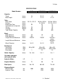
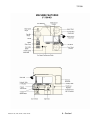
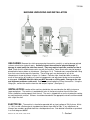
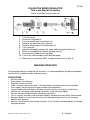
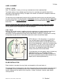
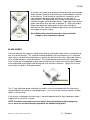
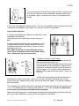
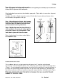
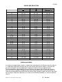
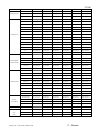
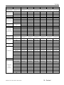
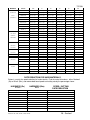
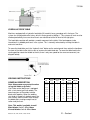
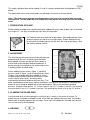
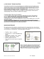
JOHNSON VERTICAL BAND SAWS
7/21/08
INSTRUCTION MANUAL AND PARTS LIST
SECTION I – Manual
FOR MODELS
E-16 (And Old Style V-16)
V-16
V-24
VH-24
V-40
VH-40
MODEL: ________________________________________
SERIAL NUMBER: ________________________________
N MANUAL AND PARTS LIST
DATE PURCHASED: ______________________________
Manual V-16, V-24, VH-24, V-40 & VH-40
DAKE Division of JSJ
724 Robbins Road
Grand Haven, Michigan 49417
616.842.7110
Phone 800-937-3253
616.842.0859
Fax 800-846-3253
Web: www.dakecorp.com
E-mail : [email protected]
[email protected]
1 – Section I
If machine is to be operated
At 440 volt 3 phase power, please
read the following warning.
7/21/08
WARNING!
This machine must be wired by a qualified
electrician. Do not connect 440-volt power directly
to this machine. You must use the optional step
down transformer (part no 300674) available at
Dake. Failure to do so may affect warranty, if
damage occurs from improper wiring.
FOREWORD
These instructions cover the installation and operation of vertical band saws. Attention
to maintenance and service will afford many years of trouble free operation. We suggest that
these instructions be retained by the department or individual responsible for the machine and
kept in a readily accessible location for reference purposes.
Manual V-16, V-24, VH-24, V-40 & VH-40
2 – Section I
7/21/08
SECTION I - TABLE OF CONTENTS
Specifications .......................................................................................
Machine Features ................................................................................
Unloading .............................................................................................
Installation ............................................................................................
Electrical ..............................................................................................
Filling Speed Regulator …………………………………………………..
Machine Operation ..............................................................................
Wheel Alignment .................................................................................
Blade Installation .................................................................................
Blade Tensioning ................................................................................
Blade Guides / Adjustment ..................................................................
Band Speed Selection .........................................................................
Saw Blade Selection………………………………………………………
Blade Break-in……………………………………………………………..
Speeds & Feeds .................................................................................
Rate Reduction Matrix For Hard Material ...........................................
Hydraulic Feed Table …………………………………………………….
Welding Instructions ............................................................................
Blade Preparation For Welding ...........................................................
Clamping / Welding / Annealing .........................................................
Re-Finishing the Weld (Grinding) .......................................................
Welder Layout & Maintenance ...........................................................
Poor Welds & Trouble Shooting .........................................................
Machine Maintenance ........................................................................
Use Of Standard Accessories ..……………........................................
Manual V-16, V-24, VH-24, V-40 & VH-40
3 – Section I
4
5-6
7
7
7
8
8
9
9
10
10-14
14
15-16
15
16-20
20
21
21
21-22
22-23
23
23
23-24
24
24-25
7/21/08
SPECIFICATIONS
Model Number:
V-16
V-24/VH-24
V-40/VH-40
Capacity:
Throat
Work Height
Inches
Inches
16
11
23-1/2
12-1/2
41
12-1/2
Table:
Work Table
Auxiliary
Height from Floor
Travel-Manual or Hydraulic
Tilt-Left
Tilt-Right
Table Weight Capacity
Inches
Inches
Inches
Inches
Degree
Degree
Lbs.
23-1/2 x 23-1/2
-38
-10
30
850
26-3/8 x 26-3/8
9 x 22-3/8
42
10
10
30
850
26-3/8 x 26-3/8
15-1/2 x 21-1/2
41
10
10
30
850
Blade:
Width Minimum
Width Maximum
Length Minimum/Maximum
Inches
Inches
Inches
1/8
5/8
128/133
1/8
1
178/187
1/8
3/4
134/140 (2
Length Minimum/Maximum
Inches
--
--
186/189 (3
Wheel Diameter
Inches
16-1/2
24-1/2
16-1/2
FPM
FPM
HP
60 to 590
-1
50 to 425
425 to 4250
2.2
50 to 425
425 to 4250
2.2
Inches
1/8 – 5/8
1/8 – 1
1/8 – 1
HP
--
1/3
1/3
Height of Machine:
Inches
72
90
78
Floor Space:
Inches
38 x 25
60 x 60
72 x 60
Lbs.
Lbs.
1000
--
2025
2225
2025
2395
Band Speed:
Low Range
High Range
Drive Motor
Welder Capacity:
VH models equipped
with hydraulic table
Hydraulic Motor:
Shipping Weight:
Manual Table
Hydraulic Table
Manual V-16, V-24, VH-24, V-40 & VH-40
wheels)
wheels)
4 – Section I
7/21/08
Manual V-16, V-24, VH-24, V-40 & VH-40
5 – Section I
7/21/08
Manual V-16, V-24, VH-24, V-40 & VH-40
6 – Section I
7/21/08
MACHINE UNPACKING AND INSTALLATION
UNLOADING: Remove the shrink-wrap covering the machine, carefully as not to damage painted
surfaces, electrical or hydraulic parts. Carefully inspect the machine for physical damage. If
damage is noted, notify the truck line at once. They may require inspection, and that a claim is
filed. Check that all standard accessories are with the machine. Some accessories may be boxed or
placed behind access doors or chip drawer. (See figure 2 & 3) The band saws are provided with lifting
eyes that screw into the top of the machine. These lifting eyes may be located in any of the
compartments shown by arrows in figure 1 & 2 above. Particular care should be taken in selecting
areas of the machine for handling, as electrical components and adjustment knobs can be marked up
or damaged. WARNING: Machine table may NOT be used as a lifting point. Damage to the saw
and alignment problems could result. Remove the mounting bolt nuts from the machine. Using the
lifting eyes, remove the machine from the skid and put in place. (See figure 1)
INSTALLATION: Location of the machine should take into consideration the ability to traverse
large work pieces. The machine is provided with holes in the base to anchor the unit to the floor.
Shims should be used to properly level the unit. The saw is shipped with an anti-rust protective coating
on machined metal surfaces. Surfaces should be cleaned with the appropriate solvent and then coated
with a light film of oil.
ELECTRICAL:
The machine is wired to be operated with an input voltage of 230, 3 phase, 60 htz
(+/- 10%) or with a Dake external step down transformer from 460v to 230v. If any adjustments or
changes are needed a qualified electrician should perform them. See detailed information as provided
in a circuit diagram #80587.
Manual V-16, V-24, VH-24, V-40 & VH-40
7 – Section I
FILLING THE SPEED REGULATOR
This is pre filled at the factory
7/21/08
These instructions are for future use
1.
2.
3.
4.
5.
6.
7.
8.
9.
10.
11.
Turn the saw on.
Screw the hand wheel in.
Turn the saw off once hand wheel is in.
Remove the mounting screws (item 6).
Remove the plug from the cylinder (Item 3).
Turn screw out.
Add oil (Lightweight hydraulic oil) slowly while turning the wheel out.
When it is completely full, replace the plug (Item 3).
Re-mount the cylinder to the saw body.
Turn on the saw and adjust to the desired speed.
When saw is at maximum RPM, re-adjust the lock nuts on Item 8
MACHINE OPERATION
Prior to performing any cutting with the machine, it is recommended that the personal become
familiar with the various controls and accessories.
PRECAUTIONS
•
•
•
•
•
•
•
•
•
•
•
No loose clothing.
Eye protection should be worn.
All guards must be in position.
Table is secured in place and locked. Table load capacity should be noted and not exceeded.
Extra supports may be required for large or cumbersome components.
Irregular shapes and small objects should be secured by means of a clamp or suitable fixture.
Machine and surrounding should be kept free of tools, scrap and foreign objects.
Machine should be locked out before making any adjustments.
Care in uncoiling, and coiling and installation of blades should be observed. Gloves recommended.
Storage of blades in an area near the machine will allow operating personal, to use the proper
blade for each operation.
Machine is furnished with electrical door interlocks. These interlocks should periodically be checked
for proper operation.
Manual V-16, V-24, VH-24, V-40 & VH-40
8 – Section I
7/21/08
WHEEL ALIGNMENT
V-16 & V / VH-24
Note: This alignment is factory set, but may need adjustment when replacing blade.
Two wheel machines have a bottom wheel that drives the saw blade and a top idle wheel that is
adjustable to facilitate blade tracking. The edges of the wheels are fitted with a composite material to
accommodate the tooth set.
The idle wheel may be adjusted by loosening the knurled locking collar and turning the black knob in
the center of the wheel. Turning the knob in a clockwise manner runs the blade toward the back edge
of the band wheel. A counter clockwise movement will move the blade toward the front edge of the
band wheel.
Correct tracking takes place when the blade runs approximately in the center of the wheel.
NOTE: The main casting with adjusting screws have been preset at the factory during assembly
utilizing special fixtures. No adjustment should be attempted.
V-40 / VH-40
Machines with two idle wheels in addition to the drive wheel possess tracking control on each wheel.
The top band wheel is set at the factory and no future adjustment should be necessary. *All
adjustments should be performed utilizing the third band wheel. If difficulty is encountered in tracking,
the top wheel may be reset as if the machine were to be used in the two wheel mode.
NOTE: With the V / VH-40 machines, it is possible to
have the blade appear to be tracking properly but in
actuality the two band wheels can be adjusted so they
form an intersecting planes, rather than a common plane
or parallel plane. This will result in excessive wear on
the crown on the band wheel by the blade teeth, and
severe cases, the composite material will shred or
actually come loose from the band wheel.
*If the blade does not track properly against the back up
guide bearing, there is a small amount of lateral
adjustment in the top wheel. (See figure 5) Loosen the
set screws and slide the yoke to make the blade line up
properly with the backup guide bearing.
BLADE INSTALLATION
Blade selection is based on the many factors and complexity of the work to be cut.
The blade placed on the band wheels with teeth facing toward the operator and down toward the top of
the worktable. Tension the blade to remove slack. Rotate the wheels by hand to ensure tracking is
correct, and blade will not “pop” off when machine is started. If tracking is incorrect, adjust before
starting machine.
Manual V-16, V-24, VH-24, V-40 & VH-40
9 – Section I
7/21/08
BLADE TENSIONING
The blade indicator is located inside the upper wheel compartment, on the lower left side of the idle
wheel. (See machine features graphic) The indicator has an arrow mounted on the horizontal plane,
with a corresponding scale for blade tensioning. The scale has two legends, one reads inches from 0 1”, and the second reads mm 0 - 25 mm. This allows tensioning either standard or metric blade widths.
With out tension on the blade, the indicator should read zero. As tension is applied to the blade the
needle will move accordingly, and should be tightened until the correct blade width is indicated on this
gauge. Example: Installing a 1/2” blade on the machine, tighten the hand wheel until the indicator’s
arrow is pointing to the 1/2” mark on the scale. Before starting the machine check the blades tracking
by hand as described in an earlier section.
This indicator has been calibrated at the factory. If recalibration is ever needed follow the steps below.
Using a blade tension gauge, (many times the
company that you purchase blades from can furnish
you with this gauge) tension the blade to the proper
PSI. The PSI will very from blade types (carbon, Bimetal) and blade widths. This information can be
obtained from your blade supplier. When proper
tension is achieved, loosen the setscrew in the collar
on the tensioning wheel shaft. (See figure 6) Adjust
this collar up or down on the shaft until the arrow is
pointing to the corresponding blade width. on the
indicator, Tighten setscrew.
Note: It is better to over tension the blade than to
run it under tensioned.
BLADE GUIDES
Your machine has come equipped with a set of interchangeable “V” type blade guides. A set of
guides consist of two each left hand and two each right hand guide inserts. The standard
guides furnished are 10 / 12 mm guides. Other sizes are optional, and can be purchased
separately, or as a five piece set. The five-piece set includes 3 / 4 mm (1/8 - 1/4”) 6 / 8 mm
(5/16 - 3/8”) 10 / 12 mm (standard set 1/2 - 5/8”) 16 / 20 mm (3/4”) and 25 / 32 mm (1”) The
blade width will dictate the size blade guide to be used.
Note: Never use blades larger than the rated capacity of the machine. Never use blades
narrower than guide insert. Damage will occur to guide insert and blade. Blade insert must
correspond with blade width.
Manual V-16, V-24, VH-24, V-40 & VH-40
10 – Section I
7/21/08
An analysis of the work to be performed should be made and the proper
blade selected. The blade should always be inspected before installing
on the machine. Things to look for should be the smoothness on the
sides and back edge of the weld, look for any missing teeth, or
impacted chips. The blade guides may now be selected and inserted
into both the upper and lower guide holders. Proper adjustment of these
guides takes place when they form a complete “V” shape (see graphic
below) and support the blade equally on each side. A couple of
thousands on each side of the blade will provide the running clearance
and support for contour sawing.
Note: Blade guides should be cleaned of chips each blade
change or more frequently if required.
BLADE GUIDES
The back end roller that supports the back of the blade on each guide holder contains a hardened cap
over a set of ball bearings. This should be checked periodically for free movement so it is allowed to
rotate freely as the back of the blade comes in contact with the face of this roller. Noticeable friction in
this assembly indicates it should be replaced. This can be done by removing the right hand guide
insert, moving the left hand guide up away from the bearing face. Loosen the setscrew on the bottom
of the guide holder and sliding the old bearing and shaft out and a new one in. Tighten the setscrew
and re-adjust the guides. See graphic below.
The “V” type solid blade guides and holder assemblies as furnished standard with the machine are
recommended for the majority of cutting applications. This is true for the cutting of materials at blade
speeds in the low range.
If the machine is operated in the high range, it should be operated with the high-speed roller guides,
supplied with this machine, installed.
NOTE: If machine is operated in excess of above, abnormal blade wear and breakage may
occur, due to the increased heat developed with the standard solid guides.
Manual V-16, V-24, VH-24, V-40 & VH-40
11 – Section I
7/21/08
HIGH SPEED ROLLER GUIDES
Applications and Advantages:
Friction and abrasive cutting, filing operations, aluminum and woodcutting.
These guides eliminate having to change inserts when changing to blades of different widths.
Requirements for Installation:
These roller guides must be installed using a new 1/2” blade width band for proper alignment.
The 1/2” band should be tracked within the approximate center line of the band wheels.
Note: Be certain band wheels are clean are free of any foreign material build up before
proceeding.
Tools / Hardware Required:
Drill - 7/16”
Drill and tap for ¼” 20 set screw
¼” 20 set screw 1/4 - 3/8” long
Upper Guide Installation:
1: Remove the existing guide holder assembly (part A)
via the 2 countersunk socket head cap screws located
on the backside of the moveable guide arm post. (Part
B) Store the original guide holder assembly for future
use. Remove the lower (red painted, part C) hold
down foot located at the bottom of the movable guide
arm post. (See graphic below)
2: With a 7/16” drill the bottom guide-mounting hole
out. Drill from the front of the guidepost, to a depth of
approx. 1”. The hole should be just deep enough to
stop short of breaking through the countersunk portion
of the hole.
3: Drill and tap a hole for a ¼” 20 set screw approx. ½ - ¾” back from the front edge of the guidepost.
This hole must be centered (intersect) with the 7/16” hole. As shown above.
Manual V-16, V-24, VH-24, V-40 & VH-40
12 – Section I
7/21/08
4: Insert the mounting stud (B) into the guide casting (A). Keep the stud
flush with the front of the casting. Keeping the mounting stud flat area
on the bottom, tighten securely the set screw (C) on the bottom of the
casting.
5: Insert this stud and guide assembly into the 7/16” hole in the guidepost. Make sure upper roller guide
is plumb with the guidepost. Lightly tighten set screw you installed in the guidepost.
Lower Guide Installation:
6: Remove lower blade guide. Replace this guide with the high
speed guide containing the
mounting bracket with slotted hole, reusing existing nuts /
bolts.
Position assembly upward along the slotted bracket, so that
the guide body casting has enough clearance to allow the
work table to be tilted for angle cutting. Tighten the socket
head cap screw or nut.
Note: Make certain that if a socket head cap screw is
used, it does not bottom out into the main saw casting
item 1. Shorten the cap screw if necessary
7: Alignment of Upper / Lower Guides:
With blade properly tensioned and tracked, position the
back-up roller by loosening the set
screw (A) on the front of the guide casting, and move the
knurled knob left to right until blade is in alignment with
the groove in the bearing. Rotate the knurled knob until
you have approx. 1/16” clearance from the back of the
blade to the front edge of the back-up roller. Tighten set
screw (A).
The two roller bearings below the back up bearing can
be adjusted in and out, left and right. Loosen the set screws that retain the bearing stems into the
casting. Using the single bearing assembly, position these bearings approx. 1/16” behind the deepest
gullet of the blade.
The single bearing assembly along with the adjustably of the upper guide roller will service blades from
¼” to ¾” The double roller set is used only when blade of ½” to 1” are used. Note: The adjustments
are the same for both single and double bearing assemblies.
Rotate eccentric bearing stems until both blade and the back up bearing groove are parallel with each
other. Set screws should be just snug up until actual alignment is confirmed.
Manual V-16, V-24, VH-24, V-40 & VH-40
13 – Section I
7/21/08
Repeat this process for the lower guide assembly.
Note: Upper guide stud may be adjusted in or out in the guide post to allow proper clearance for
blade, and for alignment with lower guide.
Align backup bearing as previously described for upper guide. Tighten both set screws when alignment
is confirmed.
Re-adjust side rollers. (Graphic in previous column) Set the side clearance distance between rollers
and saw blade, leaving about a .004 gap.
Note: If the adjustment setting for side clearance
between roller and blade is not enough, the side
rollers will cause the blade to miss-track or be
pushed outward from the guide rollers.
Note: If blade alignment from band wheel to
roller guides is necessary, do so by rotating
eccentric shafts on the roller guides. Then
lock them in place with the set screws.
After all adjustments have been made, tighten
all components tight.
BAND SPEED SELECTION
The saw blade is driven by a single speed transmission on the 16” machine and dual speed
transmissions on the 24” and 40” machines. The shifting lever on the larger models has three positions.
(Figure 1) The center being the neutral position, for set up. With the machine off, move the shift lever to
the left for low speed range (50-500 FPM) and to the right for the high speed range. (500-5000 FPM)
To shift the machine the shift lever handle must be pulled outward and then shifted left or right. (Figure
2)
WARNING: NEVER SHIFT WHILE THE MOTOR IS RUNNING. THIS WILL CAUSE EXTENSIVE
DAMAGE TO THE DRIVE TRAIN.
Manual V-16, V-24, VH-24, V-40 & VH-40
14 – Section I
7/21/08
Note: Occasionally the drive wheel may have to
be jogged by hand to engage the transmission
lever.
The variable speed is achieved through the use of a
variable regulator. (Figure 3) This is turned clockwise
or counter- clockwise to obtain an increase or
decrease in blade speed, in either range. Adjust until
desired speed is reached as read on the blade
speed gauge.
WARNING: DO NOT ADJUST THE VARIABLE SPEED CONTROL (FIGURE 3) SPEED UNLESS
THE MACHINE IS IN OPERATION! FAILURE TO DO SO WILL CAUSE SEALS TO FAIL, AND
RENDER THE UNIT INOPERABLE.
SAW BLADE SELECTION
There are numerous types of saw blades available depending upon the application. Tooth pitch, form,
tooth set, and blade composite make up all contribute to the desired cut. Blade speeds and feed are
also a factors. The complexity of the subject cannot be properly detailed in this manual, and it is
suggested that you contact your local blade supplier for more detailed information and
recommendations for the application.
Below is a chart that can be used as a guide line for blade selection and a percentage chart for
determining the speeds and feeds for material after determining the Rockwell hardness.
The chart below shows material shape and sizes of square solid, round solid, and tubing, channel, and
angle. The size range from 0” - 12” is diameter; the column under the shapes gives recommendation of
a vari-tooth blade. Example: 4” round solid, will require a 3/4 pitch blade.
Note: For structurals and tubing, determine the average width of cut.
Blades must be broke in properly, for longest life and best cut finish. Break in cutting should be
done at 1/3-1/2 normal cutting rate, for the 50-100 square inches.
NOTE: Below are the three most commonly used types of blades. The Bi-Metal blade is the most durable, for standard types of cutting
applications. The teeth are made of high speed steel and welded to a backing material. The cutting edge contains 8% cobolt with a Rc of 64
to 68. (These blades are more difficult to weld than standard carbon.) The carbon blade is the least expensive with reduced blade life. The
back of the blade is made of hardened material with a Rc of 31 to 37 and tooth hardness of 64 to 66. The carbide tipped blade has carbide
inserts welded to the blade teeth with a Ra rating of 92
Manual V-16, V-24, VH-24, V-40 & VH-40
15 – Section I
7/21/08
SAW BLADE SELECTION
MATERIAL SHAPE
MATERIAL SHAPE
MATERIAL SHAPE
INCHES
TOOTH SELECTION
TOOTH SELECTION
TOOTH SELECTION
0
.1
.2
.3
.4
.5
.6
.7
.8
.9
1
1 1/4
1 1/2
1 3/4
2
2 1/4
2 1/2
2 3/4
3
3 1/4
3 1/2
3 3/4
4
5
6
7
8
9
10
11
12
14 / 18
14 / 18
14 / 18
10 / 14
8 / 12
8 / 12
6 / 10
6 / 10
5/8
5/8
5/8
4/6
4/6
4/6
4/6
4/6
3/4
3/4
3/4
3/4
3/4
3/4
3/4
2/3
2/3
2/3
1.4 / 2.5
1.4 / 2.5
1.4 / 2.5
1.4 / 2.5
1.4 / 2.5
14 / 18
14 / 18
14 / 18
14 / 18
10 / 14
8 / 12
8 / 12
6 / 10
6 / 10
5/8
5/8
5/8
4/6
4/6
4/6
4/6
4/6
4/6
3/4
3/4
3/4
3/4
3/4
3/4
3/4
2/3
2/3
2/3
1.4 / 2.5
1.4 / 2.5
1.4 / 2.5
14 / 18
14 / 18
14 / 18
10 / 14
8 / 12
6 / 10
5/8
5/8
5/8
5/8
4/6
4/6
4/6
4/6
3/4
3/4
3/4
3/4
3/4
3/4
3/4
2/3
2/3
2/3
2/3
1.4 / 2.5
1.4 / 2.5
1.4 / 2.5
1.4 / 2.5
1.4 / 2.5
1.4 / 2.5
MATERIAL IN
SPEEDS AND FEEDS
As important as proper blade selection, is proper feeds and speeds for the different materials to be cut.
It is impossible to determine absolute rates for each material and machine, below is a chart that will
give you staring points for most applications; keeping in mind these are only approximations.
The left hand column, labeled Material tells you the family, the column Alloy lists the types that are
within that family of material. The top six columns give material dimensions. Below these column are
listed the recommended FPM and SIPM for that material type. Example: Carbon steel with a alloy make
up classified as 1030, with a diameter of 4” will be cut at 329 FPM and SIPM of 14, shown as fpm 329
sipm 14.
Manual V-16, V-24, VH-24, V-40 & VH-40
16 – Section I
7/21/08
MATERIAL
ALUMINUM ALLOY
COPPER ALLOY
ALLOY
1/2"
1"
2"
4"
7"
12"
1100,2011,2017,2024
fpm 568 sipm 7
fpm 577 sipm 11
fpm 536 sipm 16
fpm 498 sipm 21
fpm 451sipm 23
fpm 389 sipm 24
3003,5052,5086,6061
fpm 568 sipm 7
fpm 577 sipm 11
fpm 536 sipm 16
fpm 498 sipm 21
fpm 451sipm 23
fpm 389 sipm 24
6063,6101,6262,7075
fpm 568 sipm 7
fpm 577 sipm 11
fpm 536 sipm 16
fpm 498 sipm 21
fpm 451sipm 23
fpm 389 sipm 24
356,360
fpm 511 sipm 7
fpm 501 sipm 10
fpm 482 sipm 14
fpm 448 sipm 19
fpm 406 sipm 21
fpm350 sipm 22
353
fpm 454 sipm 6
fpm 445 sipm 8
fpm 429 sipm 12
fpm 399 sipm 17
fpm 361 sipm 19
fpm311 sipm 19
1452,187
fpm 426 sipm 6
fpm 418 sipm 8
fpm 402 sipm 12
fpm 374 sipm 16
fpm 338 sipm 18
fpm 292 sipm 18
380,544
fpm 397 sipm 5
fpm 390 sipm 7
fpm 375 sipm 11
fpm349 sipm 15
fpm 316 sipm 16
fpm 272 sipm 17
173,932
fpm 358 sipm 5
fpm 351 sipm 7
fpm 338 sipm 10
fpm 314 sipm 13
fpm 284 sipm 15
fpm 245 sipm 15
330,365
fpm 324 sipm 4
fpm 317 sipm 6
fpm 305 sipm 9
fpm 284 sipm 12
fpm 257 sipm 13
fpm 222 sipm 14
623,624
fpm 301 sipm 4
fpm 295 sipm 6
fpm 284 sipm 8
fpm 264 sipm 11
fpm 239 sipm 12
fpm 206 sipm 13
230,260,272
fpm 278 sipm 4
fpm 273 sipm 5
fpm 263 sipm 8
fpm 244 sipm 10
fpm 221 sipm 11
fpm 191 sipm 12
280,464,632,655
fpm 278 sipm 4
fpm 273 sipm 5
fpm 263 sipm 8
fpm 244 sipm 10
fpm 221 sipm 11
fpm 191 sipm 12
101,102,110,122,172
fpm 267 sipm 3
fpm 262 sipm 5
fpm 252sipm 7
fpm 234 sipm 10
fpm 212 sipm 11
fpm 183 sipm 11
1751,182,220,510
fpm 267 sipm 3
fpm 262 sipm 5
fpm 252 sipm 7
fpm 234 sipm 10
fpm 212 sipm 11
fpm 183 sipm 11
625,706,715,934
fpm 267 sipm 3
fpm 262 sipm 5
fpm 252 sipm 7
fpm 234 sipm 10
fpm 212 sipm 11
fpm 183 sipm 11
630
fpm 261 sipm 3
fpm 256 sipm 5
fpm 246 sipm 7
fpm 229 sipm 10
fpm 207 sipm 11
fpm 179 sipm 11
811
fpm 244 sipm 3
fpm 239 sipm 5
fpm 230 sipm 7
fpm 214 sipm 9
fpm 194 sipm 10
fpm 167 sipm 10
12L14
fpm 483 sipm 6
fpm 473 sipm 9
fpm 455 sipm 13
fpm 424 sipm 18
fpm 383 sipm 20
fpm 321 sipm 20
1213,1215
fpm 454 sipm 6
fpm 445 sipm 8
fpm 429 sipm 12
fpm 399 sipm 17
fpm 361 sipm 19
fpm 311 sipm 19
RESULFURIZED
1117
fpm 386 sipm 5
fpm 379 sipm 7
fpm 364 sipm 11
fpm 339 sipm 15
fpm 307 sipm 16
fpm 265 sipm 16
CARBON STEEL
1137
fpm 329 sipm 4
fpm 323 sipm 6
fpm 311 sipm 9
fpm 289 sipm 12
fpm 262 sipm 14
fpm 262 sipm 14
CARBON STEEL
1141,1144
fpm 318 sipm 4
fpm 312 sipm 6
fpm 300 sipm 9
fpm 279 sipm 12
fpm 253 sipm 13
fpm 218 sipm 13
1144 HI STRESS
fpm 318 sipm 4
fpm 312 sipm 6
fpm 300 sipm 9
fpm 279 sipm 12
fpm 253 sipm 13
fpm 218 sipm 13
1030
fpm 375 sipm 5
fpm 367 sipm 7
fpm 254 sipm 10
fpm 329 sipm 14
fpm 298 sipm 15
fpm 257 sipm 16
1008,1015,1020,1025
fpm 363 sipm 5
fpm 356 sipm 7
fpm 343 sipm 10
fpm 319 sipm 14
fpm 289 sipm 15
fpm 249 sipm 15
1035
fpm 352 sipm 5
fpm 345 sipm 7
fpm 332 sipm 10
fpm 309 sipm 13
fpm 280 sipm 14
fpm 241 sipm 14
1018,1021,1025
fpm 341 sipm 4
fpm 334 sipm 6
fpm 321 sipm 9
fpm 299 sipm 13
fpm 271 sipm 14
fpm 234 sipm 14
1026,1513
fpm 341 sipm 4
fpm 334 sipm 6
fpm 321 sipm 9
fpm 299 sipm 13
fpm 271 sipm 14
fpm 234 sipm 14
A36 (SHAPES),1040
fpm 307 sipm 4
fpm 301 sipm 6
fpm 289 sipm 8
fpm 269 sipm 12
fpm 243 sipm 13
fpm 210 sipm 13
1042,1541
fpm 284 sipm 4
fpm 278 sipm 5
fpm 268 sipm 8
fpm 249 sipm 11
fpm 225 sipm 12
fpm 195 sipm 12
1044,1045
fpm 250 sipm 3
fpm 245 sipm 5
fpm 236 sipm 7
fpm 219 sipm 9
fpm 198 sipm 10
fpm 171 sipm 11
1060
fpm 227sipm 3
fpm 223 sipm 4
fpm 214 sipm 6
fpm 199 sipm 9
fpm 180 sipm 9
fpm 156 sipm 10
1095
fpm 210 sipm 3
fpm 206 sipm 4
fpm 198 sipm 6
fpm 184 sipm 8
fpm 167 sipm 9
fpm 144 sipm 9
8615,8620,8622
fpm 273 sipm 4
fpm 267 sipm 5
fpm 257 sipm 7
fpm 239 sipm 10
fpm 216 sipm 11
fpm 187 sipm 12
NI-CR-MO
4340,E4340,8630
fpm 250 sipm 3
fpm 245 sipm 5
fpm 236 sipm 7
fpm 219 sipm 9
fpm 198 sipm 10
fpm 171 sipm 11
ALLOY STEEL
8640
fpm 227 sipm 3
fpm 223 sipm 4
fpm 214 sipm 6
fpm 199 sipm 9
fpm 180 sipm 9
fpm 156 sipm 10
E9310
fpm 199 sipm 3
fpm 195 sipm 4
fpm 188 sipm 5
fpm 174 sipm 7
fpm 158 sipm 8
fpm 136 sipm 8
TOOL STEEL
L-6
fpm 216 sipm 3
fpm 212 sipm 4
fpm 204 sipm 6
fpm 189 sipm 8
fpm 171 sipm 9
fpm 148 sipm 9
SHOCK RESISTING
S-1
fpm 227 sipm 3
fpm 223 sipm 4
fpm 214 sipm 6
fpm 199 sipm 9
fpm 180 sipm 9
fpm 156 sipm 10
TOOL
S-5
fpm 159 sipm 2
fpm 156 sipm 3
fpm 150 sipm 4
fpm 140 sipm 6
fpm 126 sipm 7
fpm 109 sipm 7
STEEL
S-7
fpm 142 sipm 2
fpm 139 sipm 3
fpm 134 sipm 4
fpm 125 sipm 5
fpm 113 sipm 6
fpm 97 sipm 6
Manual V-16, V-24, VH-24, V-40 & VH-40
17 – Section I
7/21/08
MATERIAL
ALLOY
1/2"
1"
2"
4"
7"
12"
A-6
fpm 227 sipm 3
fpm 223 sipm 4
fpm 214 sipm 6
fpm 199 sipm 9
fpm 180 sipm 9
fpm 156 sipm 10
COLD-WORK
A-2
fpm 204 sipm 3
fpm 200 sipm 4
fpm 193 sipm 6
fpm 179 sipm 8
fpm 162 sipm 8
fpm 140 sipm 9
TOOL STEEL
A-10
fpm 182 sipm 2
fpm 178 sipm 3
fpm 171 sipm 5
fpm 159 sipm 7
fpm 144 sipm 7
fpm 125 sipm 8
D-2
fpm 102 sipm 1
fpm 100 sipm 2
fpm 96 sipm 3
fpm 90 sipm 4
fpm 81 sipm 4
fpm 70 sipm 4
HOT-WORK TOOL
H-11,H-12,H-13
fpm 216 sipm 3
fpm 212 sipm 4
fpm 204 sipm 6
fpm 189 sipm 8
fpm 171 sipm 9
fpm 148 sipm 9
OIL HARDENING
0-1
fpm 227 sipm 3
fpm 223 sipm 4
fpm 214 sipm 6
fpm 199 sipm 9
fpm 180 sipm 9
fpm 156 sipm 10
TOOL STEEL
0-6
fpm 216 sipm 9
fpm 212 sipm 12
fpm 204 sipm 6
fpm 189 sipm 8
fpm 171 sipm 9
fpm 148 sipm 9
TOOL STEEL
W-1
fpm 256 sipm 3
fpm 251 sipm 5
fpm 241 sipm 7
fpm 224 sipm 10
fpm 203 sipm 11
HIGH-SPEED TOOL
M-1
fpm 125 sipm 2
fpm 122 sipm 2
fpm 118 sipm 3
fpm 110 sipm 5
fpm 99 sipm 5
fpm 86 sipm 5
STEEL
M-2,M-42,T-1
fpm 114 sipm 1
fpm 111 sipm 2
fpm 107 sipm 3
fpm 100 sipm 4
fpm 90 sipm 5
fpm 78 sipm 5
T-15
fpm 79 sipm 1
fpm 78 sipm 1
fpm 75 sipm 2
fpm 70 sipm 3
fpm 63 sipm 3
fpm 54 sipm 3
A242(1) COR-TEN A
fpm 341 sipm 4
fpm 334 sipm 6
fpm 321 sipm 9
fpm 299 sipm 13
fpm 271 sipm 14
fpm 234 sipm 14
WATER-HARD
fpm 175
sipm 11
ALLOY
A242(2) COR-TEN B
fpm 307 sipm 4
fpm 301 sipm 6
fpm 289 sipm 8
fpm 269 sipm 8
fpm 243 sipm 13
fpm 210 sipm 13
STEEL
300M,HY-80,HY-100
fpm 182 sipm 2
fpm 178 sipm 3
fpm 171 sipm 5
fpm 159 sipm 7
fpm 144 sipm 7
fpm 125 sipm 8
HP 9-4-20,HP 9-4-25
fpm 119 sipm 2
fpm 117 sipm 2
fpm 113 sipm 3
fpm 105sipm 4
fpm 95 sipm 5
fpm 82 sipm 2
MN ALLOY
1330
fpm 250 sipm 3
fpm 245 sipm 5
fpm 236 sipm 7
fpm 219 sipm 9
fpm 198 sipm 10
fpm 171 sipm 11
STEEL
1345
fpm 238 sipm 3
fpm 234 sipm 4
fpm 225 sipm 7
fpm 209 sipm 9
fpm 189 sipm 10
fpm 163 sipm 10
41L40
fpm 312 sipm 4
fpm 306 sipm 6
fpm 295 sipm 9
fpm 274 sipm 12
fpm 248 sipm 13
fpm 214 sipm 13
4130
fpm 307 sipm 4
fpm 301 sipm 6
fpm 289 sipm 8
fpm 269 sipm 12
fpm 243 sipm 13
fpm 210 sipm 13
CR-MO
e.t.d.'
150
fpm 284 sipm 4
fpm 278 sipm 5
fpm 268 sipm 8
fpm 249 sipm 11
fpm 225 sipm 12
fpm 195 sipm 12
ALLOY STEEL
4140,4142
fpm 284 sipm 4
fpm 278 sipm 5
fpm 268 sipm 8
fpm 249 sipm 11
fpm 225 sipm 12
fpm 195 sipm 12
4145
fpm 238 sipm 3
fpm 234 sipm 4
fpm 225 sipm 7
fpm 209 sipm 9
fpm 189 sipm 10
fpm 163 sipm 10
4150
fpm 227 sipm 3
fpm 223 sipm 4
fpm 214 sipm 6
fpm 199 sipm 9
fpm 180 sipm 9
fpm 156 sipm 10
5160
fpm 250 sipm 3
fpm 245 sipm 5
fpm 236 sipm 7
fpm 219 sipm 9
fpm 198 sipm 10
fpm 171 sipm 11
6150
fpm 238 sipm 3
fpm 234 sipm 4
fpm 225 sipm 7
fpm 209 sipm 9
fpm 189 sipm 10
fpm 163 sipm 10
E52100
fpm 182 sipm 2
fpm 178 sipm 3
fpm 171 sipm 5
fpm 159 sipm 7
fpm 144 sipm 7
fpm 125 sipm 8
420
fpm 216 sipm 3
fpm 212 sipm 4
fpm 204 sipm 6
fpm 189 sipm 8
fpm 171 sipm 9
fpm 148 sipm 9
430
fpm 170 sipm 2
fpm 167 sipm 3
fpm 161 sipm 5
fpm 149 sipm 6
fpm 1235sipm 7
fpm 117 sipm 7
CR ALLOY STEEL
CR STAINLESS
410,502
fpm 159 sipm 2
fpm 156 sipm 3
fpm 150 sipm 4
fpm 140 sipm 6
fpm 126 sipm 7
fpm 109 sipm 7
STEEL
414
fpm 131 sipm 2
fpm 128 sipm 2
fpm 123 sipm 4
fpm 115 sipm 5
fpm 104 sipm 5
fpm 90 sipm 6
431
fpm 108 sipm 1
fpm 106 sipm 2
fpm 102 sipm 3
fpm 95 sipm 4
fpm 86 sipm 4
fpm 74 sipm 5
440C
fpm 91 sipm 1
fpm 89 sipm 2
fpm 86 sipm 2
fpm 80 sipm 3
fpm 72 sipm 4
fpm 62 sipm 4
MOLD STEEL
P-20
fpm 261 sipm 3
fpm 256 sipm 5
fpm 246 sipm 7
fpm 229 sipm 10
fpm 207 sipm 11
fpm 179 sipm 11
STAINLESS STEEL
CUSTOM 450,456
fpm 91 sipm 1
fpm 89 sipm 2
fpm 86 sipm 2
fpm 80 sipm 3
fpm 72 sipm 4
fpm 62 sipm 4
304,324
fpm 136 sipm 2
fpm 134 sipm 3
fpm 129 sipm 4
fpm 120 sipm 5
fpm 108 sipm 6
fpm 93 sipm 6
304L
fpm 131 sipm 2
fpm 128 sipm 2
fpm 123 sipm 4
fpm, 115 sipm 5
fpm 104 sipm 5
fpm 90 sipm 6
347
fpm 125 sipm 2
fpm 122 sipm 2
fpm 110 sipm 5
fpm 99 sipm 5
fpm 86 sipm 5
AUSTENITIC
316,316L
fpm 114 sipm 1
fpm 111 sipm 2
fpm 107 sipm 3
fpm 100 sipm 4
fpm 90 sipm 5
fpm 78 sipm 5
STAINLESS STEEL
18-18-2,309
fpm 102 sipm 1
fpm 100 sipm 2
fpm 96 sipm 3
fpm 90 sipm 4
fpm 81 sipm 4
fpm 70 sipm 4
310
fpm 91 sipm 1
fpm 89 sipm 2
fpm 86 sipm 2
fpm 80 sipm 3
fpm 72 sipm 4
fpm 62 sipm 4
22-13-5
fpm 68 sipm 1
fpm 67 sipm 1
fpm 64 sipm 2
fpm 60 sipm 3
fpm 54 sipm 3
fpm 47 sipm 3
NITRONIC 50,60
fpm 68 sipm 1
fpm 67 sipm 1
fpm 64 sipm 2
fpm 60 sipm 3
fpm 54 sipm 3
fpm 47 sipm 3
Manual V-16, V-24, VH-24, V-40 & VH-40
fpm
118 sipm 3
18 – Section I
7/21/08
MATERIAL
ALLOY
1/2"
1"
2"
4"
7"
12"
MARTENSITIC
STAINLESS STEEL
GREEK ASCOLOY
fpm 108 sipm 1
fpm 106 sipm 2
fpm 102 sipm 3
fpm 95 sipm 4
fpm 86 sipm 4
fpm 74 sipm 5
416
fpm 216 sipm 3
fpm 212 sipm 4
fpm 204 sipm 6
fpm 189 sipm 8
fpm 171 sipm 9
fpm 148 sipm 9
FREE MACHINING
440 F
fpm 182 sipm 2
fpm 178 sipm 3
fpm 171 sipm 5
fpm 159 sipm 7
fpm 144 sipm 7
fpm 125 sipm 8
STAINLESS STEEL
203 EZ,430 F
fpm 170 sipm 2
fpm 167 sipm 3
fpm 161 sipm 5
fpm 149 sipm 6
fpm 135 sipm 7
fpm 117 sipm 7
303,303 PB,303 SE
fpm 159 sipm 2
fpm 156 sipm 3
fpm 150 sipm 4
fpm 140 sipm 6
fpm 126 sipm 67
fpm 109 sipm 7
FERRITIC
FERRALIUM 255
fpm 102 sipm 1
fpm 100 sipm 2
fpm 96 sipm 3
fpm 90 sipm 4
fpm 81 sipm 4
fpm 70 sipm 4
AUSTENITIC S.S.
2205
fpm 91 sipm 1
fpm 89 sipm 2
fpm 86 sipm 2
fpm 80 sipm 3
fpm 72 sipm 4
fpm 62 sipm 4
15-5 PH
fpm 91 sipm 1
fpm 89 sipm 2
fpm 86 sipm 2
fpm 80 sipm 3
fpm 72 sipm 4
fpm 62 sipm 4
PRECIPITATION
17-4 PH,17-7 PH
fpm 91 sipm 1
fpm 89 sipm 2
fpm 86 sipm 2
fpm 80 sipm 3
fpm 72 sipm 4
fpm 62 sipm 4
HARDENABLE
AM 350,AM 355
fpm 91 sipm 1
fpm 89 sipm 2
fpm 86 sipm 2
fpm 80 sipm 3
fpm 72 sipm 4
fpm 62 sipm 4
STAINLESS STEEL
PH 13-8 MO
fpm 91 sipm 1
fpm 89 sipm 2
fpm 86 sipm 2
fpm 80 sipm 3
fpm 72 sipm 4
fpm 62 sipm 4
PH 14-8 MO
fpm 91 sipm 1
fpm 89 sipm 2
fpm 86 sipm 2
fpm 80 sipm 3
fpm 72 sipm 4
fpm 62 sipm 4
PH 15-7 MO
fpm 85 sipm 1
fpm 84 sipm 2
fpm 80 sipm 2
fpm 75 sipm 3
fpm 68 sipm 4
fpm 58 sipm 4
fpm 568 sipm 7
fpm 557 sipm 11
fpm 536 sipm 16
fpm 498 sipm 21
fpm 451 sipm 23
fpm 389 sipm 24
MAGNESIUM
AZ31B MAG-
ALLOY
NESIUM ALLOY
IRON BASE
PYROMET X-15
fpm 136 sipm 2
fpm 134 sipm 3
fpm 129 sipm 4
fpm 120 sipm 5
fpm 108 sipm 6
fpm 93 sipm 6
SUPER ALLOY
A286
fpm 102 sipm 1
fpm 100 sipm 2
fpm 96 sipm 3
fpm 90 sipm 4
fpm 81 sipm 4
fpm 70 sipm 4
INCOLOY 800,801
fpm 102 sipm 1
fpm 100 sipm 2
fpm 96 sipm 3
fpm 90 sipm 4
fpm 81 sipm 4
fpm 70 sipm 4
COBALT BASE
ASTROLOY M
fpm 68 sipm 1
fpm 67 sipm 1
fpm 64 sipm 2
fpm 60 sipm 3
fpm 54 sipm 3
fpm 47 sipm 3
ALLOY
WF-11
fpm 74 sipm 1
fpm 72 sipm 1
fpm 70 sipm 2
fpm 65 sipm 3
fpm 59 sipm 3
fpm 51 sipm 3
TI-3A1-8V-6CR-4MO-4Zr
fpm 91 sipm 1
fpm 91 sipm 1
fpm 91 sipm 1
fpm 91 sipm 1
fpm 91 sipm 1
fpm 91 sipm 1
TI-8Mo-8V-2Fe-3Al
fpm 91 sipm 1
fpm 91 sipm 1
fpm 91 sipm 1
fpm 91 sipm 1
fpm 91 sipm 1
fpm 91 sipm 1
fpm 85 sipm 1
fpm 84 sipm 2
fpm 80 sipm 2
fpm 75 sipm 3
fpm 68 sipm 4
fpm 58 sipm 4
TI-5Al-2.5Sn
fpm 85 sipm 1
fpm 84 sipm 2
fpm 80 sipm 2
fpm 75 sipm 3
fpm 68 sipm 4
fpm 58 sipm 4
TI-6Al-2Sn-4Zr-2Mo
fpm 85 sipm 1
fpm 84 sipm 2
fpm 80 sipm 2
fpm 75 sipm 3
fpm 68 sipm 4
fpm 58 sipm 4
TI-2Al-11Sn-5Zr-1Mo
TITANIUM ALLOY
TI-6Al-4V
fpm 79 sipm 1
fpm 78 sipm 1
fpm 75 sipm 2
fpm 70 sipm 3
fpm 63 sipm 3
fpm 54 sipm 3
TI-7Al-4Mo
fpm 74 sipm 1
fpm 72 sipm 1
fpm 70 sipm 2
fpm 65 sipm 3
fpm 59 sipm 3
fpm 51 sipm 3
TI-8Al-1Mo-1V
fpm 74 sipm 1
fpm 72 sipm 1
fpm 70 sipm 2
fpm 65 sipm 3
fpm 59 sipm 3
fpm 51 sipm 3
fpm 97 sipm 1
fpm 95 sipm 2
fpm 91 sipm 3
fpm 85 sipm 4
fpm 77 sipm 4
fpm 66 sipm 4
INCONEL 625
fpm 114 sipm 1
fpm 111 sipm 2
fpm 107 sipm 3
fpm 100 sipm 4
fpm 90 sipm 5
fpm 78 sipm 5
INCOLOY 802,804
fpm 102 sipm 1
fpm 100 sipm 2
fpm 96 sipm 3
fpm 90 sipm 4
fpm 81 sipm 4
fpm 70 sipm 4
MONEL R405
fpm 97 sipm 1
fpm 95 sipm 2
fpm 91 sipm 3
fpm 85 sipm 4
fpm 77 sipm 4
fpm 66 sipm 4
NICKEL BASE
20CB3
fpm 91 sipm 1
fpm 89 sipm 2
fpm 86 sipm 2
fpm 80 sipm 3
fpm 72 sipm 4
fpm 62 sipm 4
ALLOY
MONEL 400,401
fpm 85 sipm 1
fpm 84 sipm 2
fpm 80 sipm 2
fpm 75 sipm 3
fpm 68 sipm 4
fpm 58 sipm 4
(*HASTELLOY)
*B,B-2,C,C-22
fpm 79 sipm 1
fpm 79 sipm 1
fpm 79 sipm 1
fpm 79 sipm 1
fpm 79 sipm 1
fpm 79 sipm 1
NICKEL ALLOY
NICKEL 200,201,205
*C-276,C-4
fpm 79 sipm 1
fpm 79 sipm 1
fpm 79 sipm 1
fpm 79 sipm 1
fpm 79 sipm 1
fpm 79 sipm 1
*F,G,G-2,3,G-30
fpm 79 sipm 1
fpm 79 sipm 1
fpm 79 sipm 1
fpm 79 sipm 1
fpm 79 sipm 1
fpm 79 sipm 1
*N,S,W,X , INCOLOY
825
fpm 79 sipm 1
fpm 79 sipm 1
fpm 79 sipm 1
fpm 79 sipm 1
fpm 79 sipm 1
fpm 79 sipm 1
Manual V-16, V-24, VH-24, V-40 & VH-40
19 – Section I
7/21/08
MATERIAL
ALLOY
1/2"
1"
2"
4"
7"
12"
INCONEL 751,X750
fpm 79 sipm 1
fpm 79 sipm 1
fpm 79 sipm 1
fpm 79 sipm 1
fpm 79 sipm 1
fpm 79 sipm 1
NICKEL BASE
WASPALOY
fpm 79 sipm 1
fpm 79 sipm 1
fpm 79 sipm 1
fpm 79 sipm 1
fpm 79 sipm 1
fpm 79 sipm 1
ALLOY
MONEL K500
fpm 74 sipm 1
fpm 72 sipm 1
fpm 70 sipm 2
fpm 65 sipm 3
fpm 59 sipm 3
fpm 51 sipm 3
(*HASTELLOY)
INCOLOY 901,903,926
fpm 68 sipm 1
fpm 67 sipm 1
fpm 64 sipm 2
fpm 60 sipm 3
fpm 54 sipm 3
fpm 47 sipm 3
INCONEL 600,718
fpm 68 sipm 1
fpm 67 sipm 1
fpm 64 sipm 2
fpm 60 sipm 3
fpm 54 sipm 3
fpm 47 sipm 3
NI-SPAN-C 902
fpm 68 sipm 1
fpm 67 sipm 1
fpm 64 sipm 2
fpm 60 sipm 3
fpm 54 sipm 3
fpm 47 sipm 3
NIMONIC 263
fpm 68 sipm 1
fpm 67 sipm 1
fpm 64 sipm 2
fpm 60 sipm 3
fpm 54 sipm 3
fpm 47 sipm 3
RENE 41,UDIMET 500
fpm 68 sipm 1
fpm 67 sipm 1
fpm 64 sipm 2
fpm 60 sipm 3
fpm 54 sipm 3
fpm 47 sipm 3
NIMONIC 75
fpm 57 sipm 1
fpm 56 sipm 1
fpm 54 sipm 2
fpm 50 sipm 2
fpm 45 sipm 2
fpm 39 sipm 2
ASTM A220 (50005)
fpm 273 sipm 4
fpm 267 sipm 5
fpm 257 sipm 7
fpm 239 sipm 10
fpm 216 sipm 11
fpm 187 sipm 12
CAST IRONS
ASTM A220 (60004)
fpm 193 sipm 3
fpm 189 sipm 4
fpm 182 sipm 5
fpm 169 sipm 7
fpm 153 sipm 8
fpm 132 sipm 8
PEARLITIC
ASTM A220 (70003)
fpm 165 sipm 2
fpm 161 sipm 3
fpm 155 sipm 5
fpm 144 sipm 6
fpm 131 sipm 7
fpm 133 sipm 7
MALLEABLE
ASTM A220 (80002)
fpm 142 sipm 2
fpm 139 sipm 3
fpm 134 sipm 4
fpm 125 sipm 5
fpm 113 sipm 6
fpm 97 sipm 6
ASTM A220 (90001)
fpm 114 sipm 1
fpm 111 sipm 2
fpm 107 sipm 3
fpm 100 sipm 4
fpm 90 sipm 5
fpm 78 sipm 5
ASTM A436 (1B)
fpm 170 sipm 2
fpm 167 sipm 3
fpm 161 sipm 5
fpm 149 sipm 6
fpm 135 sipm 7
fpm 117 sipm 7
GRAY IRON
ASTM A436 (2)
fpm 159 sipm 2
fpm 156 sipm 3
fpm 150 sipm 4
fpm 140 sipm 6
fpm 125 sipm 7
fpm 109 sipm 7
AUSTENITIC
ASTM A436 (2B)
fpm 142 sipm 2
fpm 139 sipm 3
fpm 134 sipm 4
fpm 125 sipm 5
fpm 133 sipm 6
fpm 97 sipm 6
DUCTILE
ASTM A439 (D-2)
fpm 91 sipm 1
fpm 89 sipm 2
fpm 86 sipm 2
fpm 80 sipm 3
fpm 72 sipm 4
fpm 62 sipm 4
AUSTENITIC
ASTM A439 (D2-B)
fpm 68 sipm 1
fpm 67 sipm 1
fpm 64 sipm 2
fpm 60 sipm 3
fpm 54 sipm 3
fpm 47 sipm 3
MALLEABLE
ASTM A47(50&53ksi)
fpm 341 sipm 4
fpm 334 sipm 6
fpm 321 sipm 9
fpm 299 sipm 13
fpm 271 sipm 14
fpm 234 sipm 14
ASTM A48 (20ksi)
fpm 261 sipm 3
fpm 256 sipm 5
fpm 246 sipm 7
fpm 229 sipm 10
fpm 207 sipm 11
fpm 179 sipm 11
ASTM A48 (40ksi)
fpm 204 sipm 3
fpm 200 sipm 4
fpm 193 sipm 6
fpm 179 sipm 8
fpm 162 sipm 8
fpm 140 sipm 9
ASTM A48 (60ksi)
fpm 114 sipm 1
fpm 111 sipm 2
fpm 107 sipm 3
fpm 100 sipm 4
fpm 90 sipm 5
fpm 78 sipm 5
ASTM A536 (60-40-18)
fpm 409 sipm 5
fpm 401 sipm 8
fpm 396 sipm 11
fpm 359 sipm 15
fpm 325 sipm 17
fpm 280 sipm 17
ASTM A536 (88-55-06)
fpm 273 sipm 4
fpm 267 sipm 5
fpm 257 sipm 7
fpm 239 sipm 10
fpm 216 sipm 11
fpm 187 sipm 12
ASTM A536 (100-70-03)
fpm 210 sipm 3
fpm 206 sipm 4
fpm 198 sipm 6
fpm 184 sipm 8
fpm 167 sipm 9
fpm 144 sipm 9
ASTM A536 (120-90-02)
fpm 136 sipm 2
fpm 134 sipm 3
fpm 129 sipm 4
fpm 120 sipm 5
fpm 108 sipm 6
fpm 93 sipm 6
GARY IRON
DUCTILE
RATE REDUCTION FOR HARD MATERIALS
Below is a matrix for speed reduction for hard materials. Find the material hardness, either Rockwell
(Rc) or Brinell (Bhn), and reduce both band speed and cutting rate by the percentage shown.
HARDNESS (Rc)
HARDNESS (Bhn)
SPEED / CUTTING
RATE REDUCTION
Up to 20
226
0%
22
237
5%
24
247
10%
26
258
15%
28
271
20%
30
286
25%
32
301
30%
34
319
33%
36
336
35%
38
353
40%
Rockwell
Manual V-16, V-24, VH-24, V-40 & VH-40
Brinell
20 – Section I
7/21/08
HYDRAULIC FEED TABLE
Machines equipped with a hydraulic feed table (VH models) have a pumping unit in the base. The
system has an adjustable relief valve, which is factory preset at 400 p.s.i. The systems oil level must be
checked periodically to assure the oil levels are maintained at the full level of the sight glass.
The feed table regulator will provide a smooth movement to the table. If the feed appears to be
intermittent it is probably due to air in the system. This is normally exhausted by running the table in
and out a few times.
To move the feed table, push the “hydraulic start” button on the control panel then, rotate the handle on
the front of the table to the right to start or increase the table feed rate. To move the table back to the
starting position rotate the handle to the left, there is only one speed for the reverse movement (see
diagram below).
WELDING INSTRUCTIONS
GENERAL DESCRIPTION
Note: Always wear eye protection when
using this welder or grinder!
Your Dake vertical band saw is equipped
with a “resistance-type” butt welder. The
two clamp jaws of the welder hold the
blade ends together. When the welding
start knob is turned fully clockwise past the
zero setting, electric current flows through
the blade ends creating enough heat to
soften and join them.
BANDSAW
mm
WELDING
CURRENT
step *)
UPSETTING
PRESSURE
step *)
UPSETTING ANNEALING ANNEALING
WAY
mm
COLOR
TIME SEC.
6 x 0.9
1-2
1
2.5
DARK RED
15
10 x 0.9
1-2
1
3.0
DARK RED
15
12 x 0.6
1-2
1
3.0
DARK RED
15
12 x 0.9
1-2
1
3.0
DARK RED
15
13 x 0.7
1-2
1-2
3.0
DARK RED
15
16 x 0.7
1-2
1-2
3.0
DARK RED
15
19 x 0.9
1-2
1-2
3.0
DARK RED
15
25 x 0.9
1-2
1-2
3.5
DARK RED
15
Note: This welder is suitable to weld
Metal blades 3 x 0.5 - 25 x 0.8mm
bi-metal blades 6 x 0.9 - 25 x 0.9mm
Manual V-16, V-24, VH-24, V-40 & VH-40
21 – Section I
7/21/08
This welder should not be used for welding 2% and 3% tungsten-alloyed metal cutting blades or HSS
blades.
The approximate valves for bi-metal blades are indicated in the matrix in the next column.
Note: * The weld current step and upsetting pressure step have to be increased with some saw
manufactures. The saw blade has to be metallically clean and no tooth may enter into the welding
seam.
1. PREPARATION OF BLADE
Before welding the blade ends should be cleaned or rubbed with emery cloth on both sides of the blade
to a length of 1”, until they are metallically clean over the enter width.
Cut the blade ends accurately and at right angles. (See graphic below) Check
abutment against the stop for a cut at right angles. Proper welding can only
be achieved if the blade ends are cut with out a burr and at right angles. (Also
see trouble shooting section)
2. ADJUSTMENT
The initial jaw gap and upset force must be adjusted and
proportioned to the cross sectional area of the blade
being welded. A greater jaw gap will allow a wider or
thicker blade to reach proper welding temperature. A
greater upset pressure produces the same unit pressure
in welding a wider or thicker blade.
Set the welding current switch (1 figure 1), upsetting
pressure switch (2 figure 1) and the upsetting way switch
(3 figure 1) to the blade width to be welded. In view of
the wide range of material qualities and thickness scale
values are only guide values, which have been
calculated for commercial blades of 0.65 mm thick. Trial
welds should determine the correct settings for different steel qualities and thickness. Particularly thin
blades (0.4 mm) should be welded with a short upsetting way, high current and weak upsetting
pressure. Example: Blade width is 1/2”. Current switch is set to 1/2” (number 1) position. The upsetting
pressure switch is set to 1/2” (number 1) position. The upsetting way switch is set to the 1/2” position.
3. CLAMPING THE BLADE ENDS
Insert the blade ends in the clamping jaws so that the joist is exactly in the center of the jaws. To
protect the jaws the blades should be inserted so the teeth are aligned at the front stops. Only blades
without teeth should be aligned at the rear stops. Leave slack in the blade coil, the blade must be free
so it can move easily during welding.
4. WELDING
Manual V-16, V-24, VH-24, V-40 & VH-40
22 – Section I
7/21/08
Turn the upsetting switch (3 figure 1) past the position (5 figure 1) to welding (6 fig. 1) and lock it for
about 3 seconds until the welding is completed. The current is switched off automatically.
Sparks spray out during welding, therefore stand at the side of the machine.
WARNING: BLADE WILL BE HOT!
5. ANNEALING
When the blade is heated in the butt welding process, the steel at the point of the weld “air hardens”
and becomes brittle. The anneal on/off knob is used to anneal the weld by reheating it. This returns the
blade close to its original condition.
After welding loosen the pressure clamps (7 fig. 1) and set the jaws to the wide annealing position by
turning the upsetting pressure switch (2 fig. 1) counter clockwise. Re-clamp the blade so that the weld
is in the center between the jaws. Operate the annealing switch (8 fig.1) until the weld becomes dark
cherry red. This will take from 1 to 5 seconds depending on the blade width. Allow blade to cool until
the blade returns to a dark color. Repeat this process at least three times. Some brittle alloys require
more annealing than the standard carbon blades.
Note: It is difficult to weld and anneal bi-metal blades due to the make up of this type of blade. It
will take some practice to successfully achieve a suitable weld.
WARNING: BLADE WILL BE HOT!
After annealing bend test your weld:
6. RE-FINISHING THE WELD
Welding burr (flash) can be removed by finishing with a grinding wheel above the welder. Grind in a
longitudinal direction, other wise transverse fractures may occur. The proper finish of the blade after
grinding, a tempered steel-blue coloring.
Note: Do not over grind, into the blade facing. Remove any burr on the back edge of the blade.
WELDER LAYOUT AND CONTROLS
7. WELDER MAINTENANCE
If the clamping areas of the jaws are dirty or deformed so they so not clamp
evenly, good welds cannot be made. Any dirt or metallic debris must be
removed from the jaws. The jaws should never be filed. It should only be
polished with a proper cleaning material and if absolutely necessary polished
with fine emery cloth held on a flat piece of bar stock. The uniformity of current
flow and contact pressure can be checked by putting the welder in the
annealing position and clamping a piece of blade stock with out a weld in the
jaws. When the annealing switch is turned to the heating position the blade
should heat uniformly over its entire width. (See fig. 2) If the heating is not
uniform the clamping devices should be checked for dirt or misalignment.
Manual V-16, V-24, VH-24, V-40 & VH-40
23 – Section I
figure 2
7/21/08
8. POOR WELDS / TROUBLE SHOOTING
If the welded seam contains holes, the upsetting pressure should be increased, the welding current
reduced or both settings changed. We must emphasize once again that proper welds cannot be
made if the blade ends are not cut square, and properly cleaned. Welding of blades may take
practice, do not be discouraged if your welds are not perfect at first.
Avoid overlapping when welding thin blades. If welder does not give suitable weld, check in coming
voltage to the machine. If voltage is low, use next blade size setting. Example: 220 volt machine,
incoming voltage is 208 volt, to weld 1/2” blade use 5/8” settings.
If incoming voltage is high reverse this procedure.
If incoming voltage is low, the welder transformer has taps that can be set to a 10% increase or
decrease. SHOCK HAZARD! ONLY A QUALIFIED ELECTRICIAN SHOULD ATTEMPT THIS.
ALWAYS CONTACT DAKE BEFORE REMOVING THE WELDER.
If the welder does not shut off, after the welding cycle, or will not start the welding cycle, a limit switch
adjustment is needed.
THE WELDER MUST BE REMOVED FOR THIS ADJUSTMENT. SHOCK HAZARD! ALWAYS
CONTACT DAKE BEFORE REMOVING THE WELDER OF MAKING INTERNAL ADJUSTMENTS. A
QUALIFIED ELECTRICIAN MUST DO THESE ADJUSTMENT.
MACHINE MAINTENANCE
The maintenance of the machine is naturally based on the usage rather than a time element.
The following is a recommendation based-on-average usage, and adjustment to the frequency
can be made on an individual basis. See below graphic for locations.
•
•
•
•
•
•
Chip Pan - clean - as required.
Band wheel tires - remove embedded chips weekly.
Blade guide assemblies - clean - weekly.
Gear box - drain and refill - yearly
Monitor Hydraulic Reservoir.
Drain water from water trap on air regulator
weekly.
Note: If raising the guide post more than half way up
from the table, and guide post cranks up hard, the
upper blade guard must be removed. See figure A&B
Blade will still be contained in the upper position.
Manual V-16, V-24, VH-24, V-40 & VH-40
24 – Section I
7/21/08
USE OF STANDARD AND OPTIONAL
ACCESSORIES
CIRCLE CUTTING (OPTIONAL) (figure 1)
(Assembly part number 714801)
The device is used for cutting out perfectly round
objects. Insert the round bar into the corresponding
hole in the guide post, secure with set screw.
Gross radius changes are made moving the cast
assemblies on the round bar, fine adjustments are
done with the thumb wheel.
RIP FENCE Standard all models (figure 2)
(Part number 714805 – Model 24/40/F-16)
(Part number 714869 – Model E-16 only)
Used for cutting material in accurate straight lines. To
attach, insert T-bolt provided in the T-slot in the front of
the table. Slide into the desired position and tighten
handle.
PROFILE CUTTING ATTACHMENT Standard on VH-24 / VH-40 models (figure 3)
(Part number 714821)
This device is used for cutting irregular shapes with
the hydraulic table. Set the chain up as shown in
figure 3. Set the material in the holder and guide with
the hand wheel on the right side of the table. The
excess chain should be coiled out of the way, while
operating the machine.
Note: When chain is not engaged in the rear
sprocket the angle of cut is controlled by guiding
the handles on the holder.
PROTRACTOR HEAD
Standard on 24/40 models. Optional for 16 models
(figure 4)
(Assembly Part number 714800 24/40/F-16 Models)
(Assembly Part number 75561 E-16 Model)
Used for cutting angles 90 degrees to 45
degrees in relation to the blade. It is fastened to
the table by means of T-bolts. The L-shaped bar
is used for additional support of the work. This is
not factory bent.
Manual V-16, V-24, VH-24, V-40 & VH-40
25 – Section I
7/21/08
T-SLOTS
T-slots are machined into the work table for your use
with fixturing or other accessories. The dimensions
of these T-slots are furnished to the right.
Manual V-16, V-24, VH-24, V-40 & VH-40
26 – Section I