1
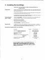
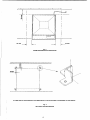
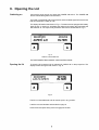
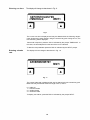
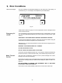
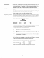
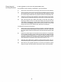
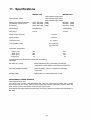
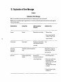
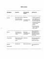
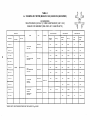
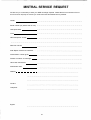
Technical Publication No. 71100-852
11 /9Ö
OPERATING MANUAL
FOR
MISTRAL 10OO & 2 0 0 0
CENTRIFUGES
PLEASE READ CAREFULLY
MSE
Bishop Meadow Road,
Loughborough, Leicestershire,
LE11 ORG England.
Tel (0509) 237371
© Sanyo Gallenkamp PLC
Registered in London No 2462454
Contents
Section
1
2
3
4
5
6
7
8
9
10
11
12
13
14
General Description
Important Information for Good Operator Practice
Installing the Centrifuge
Rotors and Accessories
- Fitting the Rotor
- Loading the Rotor
- Balancing the Rotor
- Removing the Rotor
How to operate your Mistral 1000 and 2000 Centrifuges
Opening the Lid
Parameter Entry
Starting the Run
Error Conditions
Maintenance
Specifications
Explanation of Error Messages
Rotors and Accessories
Service Instructions
Page
1
2
3
6
6
6
6
6
7
8
9
11
12
13
20
21
24
35
Illustrations
Fig. 1
Fig. 2
Fig. 3
Fig. 4
Fig. 5/12
Fig. 13
Fig. 14
Fig. 15A
15B
Front and Rear Views of the Centrifuge
Operating Clearances
Securing the Centrifuge
Control Panel and Display
Displays
Mains Fuse Access and Replacement
Refitting the Bowl
Removing the Motor Assembly
Replacing the Motor Brushes
Page
4
5
5
7
8-12
15
15
18
18
Fuse Ratings
Explanation of Error Messages
Swing-out Rotors and Accessories
Angle Rotors and Accessories
Microtitration Rotor and Accessories
Page
14
21
24-30
31-33
34
Tables
Table 1
Table 2
Table 3-9
Table 10-12
Table 13
Thank you for buying an MSE centrifuge. Please read the enclosed
operating manual before using your centrifuge; it will provide you and
your colleagues with useful information on all aspects of the centrifuge
and its accessories.
As our customer, we should like to ensure that you are totally satisfied
at all times. Do not hesitate to contact MSE - your views are very
important to us.
MSE Scientific Instruments
1. General Description
The MISTRAL 1000 and 2000 high performance bench top centrifuges join the well established range of MSE
MISTRAL centrifuges.
The MISTRAL range now consists of:
MISTRAL 1000
MISTRAL 2000
MISTRAL 3000i
MISTRAL 3000E
MISTRAL 6000
The entire MISTRAL range of centrifuges has been designed to meet the present and future demands of routine
and research laboratories.
A comprehensive range of rotors and accessories are available to accommodate the most commonly used
centrifuge tubes and bottles.
In the MISTRAL 1000 and the MISTRAL 2000, MSE have utilised the best of current technology to produce the
most advanced, safe and reliable instruments possible.
ADVANCED DESIGN FEATURES INCLUDE:
* INTELLIGENT MICROPROCESSOR CONTROL
* LCD DISPLAY/CONTROL PANEL
* AUTOMATIC ROTOR IDENTIFICATION SYSTEM
* SPEED CONTROL TO WITHIN ±25 rpm
* RUN TO RCF (RELATIVE CENTRIFUGAL FORCE)
* LAST RUN RECALL
* OVERSPEED PREVENTION
* FULL LID INTERLOCK
* IMBALANCE MONITOR
* BRAKE RATE SELECTION
* SELF-DIAGNOSTIC DISPLAY
* ROBUST MOULDED BODY
* REMOVABLE INNER BOWL
2. Important Information for
Good Operator Practice
Spillages
In the event of liquid spillage, the affected surfaces should be cleaned immediately.
The rotor and accessories should be removed and, if necessary, the inner bowl
should be removed for thorough cleaning, (see Section 10).
Regular cleaning of the centrifuge is highly recommended to avoid the build up of
contamination.
Materials with
specific gravity in
excess of 1.2
The maximum speed of each rotor is calculated on the basis of samples with a
specific gravity of 1.2. If materials of a higher specific gravity are used, then the
maximum rotor speed must be reduced according to the formula below.
M =
1.2 X N 2
Where M =
N =
S =
Corrosive
materials
rpm
New maximum speed
Normal maximum speed
Specific gravity of sample
Where particularly corrosive materials are to be centrifuged, the samples should be
placed in sealed containers and all necessary precautions observed. The following
list gives examples of corrosive materials used in laboratories.
Phenol/cresol/water, chloroform/isoamyl alcohol, salt solutions (especially ammonium sulphate), solutions of ammonium hydroxide and acidic solutions eg
hydrochloric, trichloracetic and perchloric acids.
Other materials are often equally corrosive and the user is responsible for checking
the characteristics of solutions used.
Infective samples
Very special care is necessary when infective materials are to be centrifuged.
Sealed containers should always be used. The caps should be doublé checked to
ensure that they are not damaged and fit correctly prior to starting the centrifuge.
After use, containers and caps should be sterilised immediately, using a noncorrosive method.
IT IS ADVISABLE TO HAVE THIS CENTRIFUGE SERVICED BY A
COMPETENT ENGINEER, PREFERABLY THE MANUFACTURER'S
REPRESENTATIVE, EVERY SIX MONTHS, (SEE SECTION 10).
3. Installing the Centrifuge
IMPORTANT: THE ROTOR MUST NOT BE FITTED WHEN MOVING OR
DURING TRANSIT
Preparation
Remove the centrifuge from its packing and place it on a rigid Ievel surface. The
location of the control panel, lid lock access hole, mains power switch and mains
fuses are shown in Fig. 1A.
Check that the available power supply corresponds to that stated on the rating plate
located at the rear of the instrument, (see Fig. 1B).
It is important that at least 75 mm ciearance is allowed at the sides and rear of the
centrifuge when in final operating position, (see Fig. 2).
Connecting the
power supply
220/240V INSTRUMENT - connect the 3-core cable to a 3-pin plug, fitted with a
5 Amp fuse (Mistral 1000) or a 7 Amp fuse (Mistral 2000), as follows:
Brown wire to Live (L) terminal
Blue wire to Neutral (N) terminal
Yellow/green wire to Earth (E) terminal
120V INSTRUMENT - supplied with fitted plug.
Restraint kit
A restraint kit, to secure the centrifuge to a sound work surface, is available. It
consists of four anchor brackets, positioned at each corner of the machine base,
which are bolted or screwed to the work surface, (see Fig. 3).
Accessories supplied with each centrifuge
Description
Spare fuses M1000 120V/220V/240V
M2000 120V/220V/240V
Small electric screwdriver
Allen key for lid removal
Spindle nut
Spare set of motor brushes M1000 (220/240V)
M1000120V
M2000
Guarantee card 120V/220V/240V
Operating manual
Quantity
FIS Part Number
2
2
2
1
1
1
1
1
1
1
32600-066/063/063
32600-066/064/064
78500-096
78500-006
87120-204
34500-011
61600-005
34500-015
71100-944/941/941
71100-852
DO NOT ATTEMPT TO RUN THE CENTRIFUGE WITHOUT A
ROTOR BEING FITTED TO THE DRIVE SHAFT. FAILURE TO
COMPLY WITH THIS REQUIREMENT WILL CAUSE A 'TACHO
SIGNAL LOSS' ERROR TO BE DISPLAYED. REFER TO TABLE 2,
PAGE 22 IF THIS OCCURS.
COOLING AIR INLET
SLOTS IN LID
(DO NOT OBSTRUCT)
CONTROL PANEL
LID LOCK OVERRIDE
ACCESS HOLE
(SEE PAGE 12)
MAINS POWER
SWITCH
FIG.1A.
MAINS FUSES
SEE FIG. 13 FOR DETAILS
PLUG COVERING
LID FIXING SCREWS
RATING PLATE &
SERIAL NUMBER
MAINS CABLE
FIG.1B.
COOLING AIR EXIT SLOTS
(DO NOT OBSTRUCT)
Fig. 1AandFig. 1B
FRONT AND REAR VIEWS OF THE CENTRIFUGE
0-OFF
1 -ON
/ / / S / / / / / / / / / S / / / / / / / / / S / / / / / / / / / / / / / / S / / / / / / / / S .
75 mm
75 mm
Fig. 2.
MINIMUM OPERATING CLEARANCES
A TEMPLATE IS SUPPLIED WITH THE BRACKETS TO AID ACCURATE POSITIONING ON THE BENCH
Fig. 3
SECURING THE CENTRIFUGE
4. Rotors and Accessories
Tables 3 to 13 on pages 24 to 34, give details of the range of rotors and accessories available for use on the
Mistral 1000/2000 centrifuges. The drive head design and rotor identification system is common to both
instruments.,The rotors are therefore interchangeable between the models, with the following exceptions:
IMPORTANT: - The 4 x 200 rotor (cat no 43124-134)
and
Microtitration rotor (cat no 43121 -117)
MUST NOT BE FITTED TO THE MISTRAL 1000.
Before fitting the rotor, ensure that the drive head and rotor bore are clean.
Fitting the rotor
Locate the rotor on the drive head and tighten spindle nut firmly by hand.To increase
leverage, insert a suitable bar through the spindle nut central hole. DO NOT
OVERTIGHTEN.
Loading the rotor
Buckets, cups and trunnions are supplied as matched, balanced assemblies. It is
important that all components should be stored and used together. It is not
necessary for all the buckets to be loaded, provided that the loads are placed
symmetrically around the rotor.
THE ROTOR MUST ALWAYS BE USED WITH A FULL COMPLIMENT OF
BUCKETS!
When using the angle rotors, ensure all the pockets are clean before fitting the
buckets. When using the swing out rotor, ensure that the buckets swing freely about
their pivots.
Refer to page 2 for centrifugation of samples with the following characteristics:
- Specific gravity in excess of 1.2.
- Corrosive materials.
- Infective samples.
Balancing the
rotor
The loads should be reasonably balanced, which, in most cases, means equalising
the liquid levels by eye. In the swing out rotor do not exceed 15g between loads
when fully loaded, or 5g when partially loaded.
FAILURE TO LOAD THE ROTOR CAREFULLY WILL TRIP THE OUT OF BALANCE
SENSOR, CAUSING THE INSTRUMENT TO STOP.
Removing the
rotor
Open the lid and switch off the power. Remove all the buckets and trunnions.
Unscrew and remove the spindle nut. Grip the rotor on opposite sides and gently
rock the rotor from side to side a few times to release the rotor from the spindle. Lift
the rotor clear of the drive head. NEVER USE EXCESSIVE FORCE.
NB - If the rotor has been left on the drive head for a prolonged period of use,
removal of the spindle nut may be difficult. In this event, a suitable bar may be
inserted through the hole in the spindle nut to obtain additional leverage.
5. How to Operate your Mistral 1000 and
2000 Centrifuges
Switching on
The key pad
Connect to the power supply. Press the POWER ON switch at the front of the
instrument, (0 = OFF, 1= ON). The switch will light up and you will hear an audible
signal.
LIQUID CRYSTAL DISPLAY
NUMERIC KEYS
L CANCEL ENTRY KEY
L MULTIFUNCTIONAL KEYS
STOP KEY
_ START KEY
Fig.4
CONTROL PANEL AND DISPLAY
Understandinq the
The liquid crystal display shows two lines of information. (See Fig. 4)
control panel and
display
Top line: PARAMETER DISPLAY LINE, ie Speed, Run time, Brake, RCF.
Bottom line: PROMPT LINE indicating options open to the operator.
In the event of a run error, an appropriate message will appear on the prompt line,
together with an audible alarm.
Fig. 4 also shows that the key pad consists of several types of key:
(i)
The <$> START and © STOP keys are used to initiate and terminate a run
manually.
(ii)
Beneath the liquid crystal display are two function keys marked with a
triangle A. These are referred to as the LHK (left-hand key) and RHK (righthand key). Their role is indicated by the messages on the prompt line.
(iii)
The numeric keys are used to enter values for speed, g, time etc.
6. Opening the Lid
Switching on
Connect the power supply and press the POWER ON switch. The POWER ON
switch is illuminated green when activated.
The liquid crystal display will become active and an audible signal informs the user
that the instrument is ready for use.
The display will settle to that shown in Fig. 5. The instrument is equipped with battery
back-up and, on power up, will display the values current when the instrument was
last switched off. The top line may therefore differ from that illustrated in Fig. 5.
wooRpn
ioruns
40PEH LI0
RLTERt
Fig. 5
DISPLAY ON POWER-UP
THE INSTRUMENT NOW AWAITS YOUR INSTRUCTIONS
Opening the lid
To open the lid, press the LHK A indicated by 'OPEN LID' on the prompt line. The
display wilf rïüw change to that shown in Fig. 6.
IOOORPH
LID IS OPEH
10 /7/flS
RLTERt
Fig. 6
The lid is counter-balanced and will remain open in any position.
Load the rotor and buckets as described on page 6.
Close the lid and press firmly down to engage the lid lock.
7. Parameter Entry
Upon closing the lid, the display will revert to that shown in Fig. 5. To start the machine using the current
parameters shown on the top display line, press <]> (START).
To alter the parameters press RHK A indicated by 'ALTER' on the prompt line. The display will change to that
shown in either Fig. 7 or Fig. 8. The operator can now enter speed or RCF(g). To move between speed and
RCF(g) press the LHK • indicated by 'RPM/G' on the prompt line.
Entering speed
SETSPEED1000RPfl
tRPfl/G
nEXT'i
Fig. 7
The currently selected speed is displayed. A new speed may be entered, using the
numeric keys, within the range of 200 to 6500 rpm. If a mistake is made, simply press
CE. The display will revert to the previous speed, the new speed may now be reentered.
!
Entering an RCF
value
SETRCF500X0
iRPfl/ü
HEXT+
Fig. 8
The currently selected RCF is displayed. A new RCF value may be entered using the
numeric keys. If a mistake is made, press CE. The display will revertto the previous
speed, the new speed may now be re-entered. The microprocessor will calculate
and set the speed to achieve the RCF value set.
To alter the next parameter, press the RHK A indicated by the 'NEXT' prompt.
NB - Each rotor has a maximum speed (or RCF value). If the operator selects a
value in excess of this, the automatic rotor identification system will reduce the value
to the maximum limit.
Entering run time
The display will change to that shown in Fig. 9.
SETTII1E10niIlUTES
tTME/HOLD
IÏEXT+
Fig. 9
The current run time is displayed and may be altered within the following ranges:
0-9.9 minutes and 10-99 minutes, using the numeric key pad. During the run, the
time remaining will be displayed.
If time hold is required, press the LHK A indicated by the prompt 'TIME/HOLD'. In
this case, the time elapsed from the start of the run is indicated.
To alter the next parameter press the RHK A indicated by the 'NEXT' prompt.
Entering a brake
rate
The display will now change to that shown in Fig. 10.
SETBRRKERRTE1
ÏIEXTi
Fig. 10
The current brake rate is displayed and may be altered using the numeric key pad.
Brake rate may be entered within the range of 0 to 3, where
0
1
2
3
= brake off
= minimum brake
= medium brake
= maximum brake
To display new values, press the RHK A indicated by the prompt 'NEXT'.
10
8. Starting the Run
Ensure that the rotor is correctly loaded and fitted. Close the lid and press down
firmly to engage the lid lock. Press <J> (START).
The display will now change to show actual values of speed and run time. After a
short delay the motor will engage.
Fig. 11 shows a typical display during the run. The run status of the machine is
indicated by the messages RUNNING or AT SPEED or STOPPING. This is
displayed intermittantly with the SHOW SET message.
9<?5 RPI1
SHÖUSET
9H111115
FILTER*
Fig. 11
Examination of set
values
During the run it is possible to examine the set values by pressing the LHK •
indicated by the 'SHOW SET' prompt. The values will display for a few seconds and
then the display will revert to actual values.
Please note that the brake rate value is not displayed.
Alter ing run
parameters whilst
the centrifuge is
running
Whilst the 'ALTER' prompt is indicated, run parameters can be changed by pressing
the RHK A and following the procedure previously outlined. The instrument will
respond to the new values immediately.
Manual
termination of run
At any time the run may be stopped by pressing the © (STOP) button.
11
9, Error Conditions
Error m e s s a g e s
Any error message is intermittentiy displayed on the bottom line of the display, as
indicated in Fig. 12. The display is accompanied by an audible alarm.
32 runs
11/C HRS ItlBRLRtiCED
Fig. 12
Please refer to Table 2 on page 21 for a full explanation of each message and the
correct course of action.
Emergency lid
release
It is not possible to open the lid via the keypad if there is a power failure or if the lid
lock has been deliberately disabled by the control system for safety reasons (See
Table 2).
DISCONNECT THE POWER SUPPLY BEFORE PROCEEDING FURTHER
To open the lid under these conditions, the lid lock must be over-ridden using the
small electrical screwdriver supplied in the accessories kit.
Referring to Fig. 1A, insert the lid release tooi into the hole shown and gently push in
until the lid opens.
WARNING: THE ROTOR MAY BE STILL TURNING!
ALLOW THE ROTOR TO STOP.
DO NOT TOUCH THE ROTOR UNTIL IT IS AT REST.
The lid cannot be shut whilst the power is off. To shut the lid, insert the lid release tooi
as above and hold in. Press the lid down firmly, and simultaneously remove the tooi.
Motor Thermal
Cut Out
The drive motor is fitted with a thermal cut out to prevent damage to the motor
windings in the event of overheating.
Should this occur during a run, the power supply to the motor will be disconnected,
and the error message LOSS OF DRIVE will be displayed. (Refer to Table 2 on
page 22).
DO NOT ATTEMPT TO RESTART THE INSTRUMENT UNTIL IT HAS BEEN
CHECKED BY A QUALIFIED PERSON.
The thermal cut out will automatically reset when the motor has cooled down.
12
10. Maintenance
This section describes the basic maintenance procedures, in particular, the methods and materials used for
cleaning the centrifuge, rotors and accessories.
Cleanliness
To maintain a good appearance and to prevent dirt build-up, the casing and the
inside of the bowl shouid be cleaned regularly using a soft cloth dampened with a
neutral detergent and warm water. The key pad and display may also be cleaned in
this manner, but shouid be wiped dry immediately.
If corrosive materials are used in the centrifuge, it is especially important to clean out
the centrifuge bowl thoroughly. Pay particular attention to the cooling air louvres. If a
major spillage occurs in the bowl, the excess liquid shouid be mopped out and the
bowl then removed for final cleaning (refer to page 16 for bowl removal procedure).
Drive shaft
The drive shaft shouid be cleaned periodically with a solvent to remove excessive
grease. When clean, re-lubricate the shaft lightly with petroleum jelly.
Rotors and
buckets
The rotors and accessories shouid be handled with care to avoid damage. Prior to
storage, all components shouid be protected against corrosion using MSE Rotor
Spray (Cat No 17341-151) which is an anti-corrosion and de-waterizing agent.
The rotors, metal buckets, cups, carriers and adaptors shouid all be washed after
use with a neutral detergent and afterwards dried and stored in a dry place. Buckets
and cups shouid be stored inverted.
The pivot areas of the swing-out rotors, i.e. the pivot pins on the rotor and the slots on
the buckets, shouid be lubricated periodically with Molykote 321 R grease (a spray
can is the most convenient application method).
0-Rings
Ensure that the 0-Rings fitted to the sealing caps are lightly coated with silicone
grease. Check the 0-Rings regularly for cuts and abrasions, replacing as necessary
but at least once a year.
Lid friction
block
adjustment
Mistral 2000 only - In the event that the lid fails to lift off its catch when the open lid
key is depressed then it is most probable that the lid friction block needs adjustment.
Open the lid manually (see page 12), then turn clockwise the small socket screw,
which is visible through the small hole that is located on the underside of the lid
towards the centre-rear of the machine. A key is supplied with the machine for this
purpose.
13
Sterilisation
All of the rotors, buckets and sealing caps (with O-Rings removed) and the bowl may
be sterilised by autoclaving at 120°C, (see page 16 for bowl removal procedure).
If the means available for disinfection of certain microbiological agents are inadequate, the safety officer should be consulted and appropriate steps taken.
Lid seal
Lightly coat the lid seal with French chalk occasionally and in particular after
cleaning.
If the lip of the lid seal becomes damaged it should be replaced by following the
procedure for removing and re-fitting the bowl, (see page 16).
TO BE CARRIED OUT BY QUALIFIED PERSONNEL ONLY.
Replacing the fuse
The main power supply incorporatesa fuse protection on both the live and neutral
connections, the locations of the fuse holders are shown in Fig. 13. The main
connection plug on the 220V/240V instrument should also be fitted with a fuse.
Table 1 gives the fuse ratings for each machine:
Table 1
Fuse Ratings
Mistral 1000
Mistral 2000
120V
T10.0A
T10.0A
220V/240V
T3.15A
T5.0A
Plug 220V/240V
5.0A
7.0A
If one or both of the fuses have blown, and the machine is switched on, the display
will not function and the lamp in the Power On switch will not light up.
To replace the instrument fuse proceed as follows:
(i)
Disconnect the power supply at the main plug.
(ii)
Move the instrument until the front protrudes over the bench edge, (see
Fig. 13).
(iii)
Unscrew the fuse holder caps and remove the fuses. Inspect and replace
as necessary with the correct rating. For 220V/240V model, the plug fuse
may also need to be checked.
(iv)
Reposition the machine and connect the power supply.
NB - If the fuse blows immediately or blows again during normal use, the power
supply should be disconnected and the service engineer called.
Additional fuses are located internally on the P.C.B. - ratings as follows:Mistral 1000/2000 FS1
FS2
120V
T250mA
T1.0A.
220/240V
T100mA
T315mA
If failure of a P.C.B, fuse is suspected, contact your service engineer.
14
MAINS FUSE HOLDERS
SEE TABLE 1 FOR CORRECT
FUSE RATING
PULL INSTRUMENT TOWARDS FRONT
OF THE BENCH
Fig. 13
MAINS FUSE ACCESS AND REPLACEMENT
LID SEAL
PUSH
DOWN
AT BASE
BOWL
MOULDED CASE
CORRECT POSITION OF LID SEAL
Fig. 14
REFITTING THE BOWL
15
Removing and
re-fitting the bowl
TO BE CARRIED OUT BY QUALIFIED PERSONNEL ONLY.
_
#.
.
.,
.
.
. ... ..
.
. ..
To remove the bowl for cleaning or stenlisation, proceed as follows:
(i)
Open the lid, disconnect the power supply and remove the rotor assembly.
(ii)
Turn the machine around and remove the four hole-blanking plugs covering
the lid fixing screws, (see Fig. 1B). With the lid fully open (vertical), remove
the screws using the M5 Allen key provided and lift the lid assembly clear.
(iii)
Using the air louvres as grip (situated on the inside front face of the bowl),
pull upwards and release the top flange of the bowl from the lid seal recess.
(iv)
Next, push the skirt of the rubber motor gaiter in and down and obtain a
finger grip under the inner run of the bowl. Starting at the front where the
bowl flange is already free, work around the bowl circumference, easing
back the seal whilst puiling upwards at the centre of the bowl. Once the top
flange of the bowl is free of the lid seal, lift the bowl out squarely.
To replace the bowl proceed as follows:
(i)
Inspect the lip of the lid seal and replace if necessary. Refit the lid seal with
the two ends closely butted together and with the join to the rear. Check that
the motor gaiter is seated correctly with the air inlet slots flush with the metal
base.
(ii)
Fit the bowl, positioning the louvres at the front of instrument. This operation
may be aided by applying French chalk to the lid seal and rotating the bowl
from side to side as it is pushed down. Using the screwdriver blade, hook the
lid seal lip outwards at a convenient point, applying downwards pressure
while working the bowl flange into the seal recess, (see Fig. 14).
(iii)
Hook the motor gaiter back in position to seal around the bowl inner rim.
Check that the top end of the gaiter is correctly f itted on to the top moulding.
(iv)
Re-fit the lid in the opposite sequence to removal. Re-connect the power
supply and open and close the lid a few times to check correct operation.
16
Replacing the
motorbrushes
TO BE CARRIED OUT BY QUALIFIED PERSONNEL ONLY.
...
_
(i)
Open the lid, disconnect the power supply and remove the rotor assembly.
Remove the bowl as described earlier, (see page 16).
t.
... ..
.t.
.
(ii)
Pinch the top section of the rubber motor gaiter and pull up and over the
plastic moulding.
iU
NB - Do not pull the gaiter up more than is necessary to gain access with a
'Posidrive' screwdriver as shown in Fig. 15A.
(iii)
Viewing around the side of the motor, the heads of the three clamping
screws securing the motor assembly to the base moulding are clearly
visible. Unscrew each one by approximately 5 turns and use the end of the
screwdriver to swivel the damp plate through 90°.
(iv)
Note the orientation of the motor assembly and then tilt to one side and lift
out through the hole.
It is not necessary to unplug the main harness or to disconnect the earth
lead.
(v)
With reference to Fig. 15B, remove the old brushes, noting carefully the
relationship between the components.
The area in the vicinity of the brush housing must be completely cleared
of carbon dust. Use airline or similar to blow area clear.
Fit the new set of brushes, ensuring that they move freely within the carrier
and that the spring is effective. Important: The pigtails of the 120V Mistral
1000 motor brushes must be coiled behind the spring as shown. When
fitting this brush assembly to the motor the pigtail must be located in the
groove of the brush housing, ensuring that the pigtail is not trapped
between the housing and carrier.
(vi)
Re-locate the motor assembly in the same orientation as previously noted.
Check that the wiring harness, and in particular the earth lead, is not
trapped under the motor mount plate.
Swivel the damp plates back into position and lightly tighten each damp
screw. Finally tighten each screw to a torque setting of 2.3 Nm (20lb in).
Re-position the motor gaiter and replace the bowl and lid as described
earlier, (see page 16).
(vii)
Run the centrifuge with an unloaded rotor (with a full complement of
buckets) for half an hour at 1000 rpm to bed in the brushes.
t7
Fig. 15A
REMOVING THE MOTOR ASSEMBLY
PIGTAIL MUST BE COILED BEHIND SPRING
BRUSH UNIT HOLDER
BRUSH
SPRING
MISTRAL 1000 - 120V
MISTRAL 1000 - 220/240V
MISTRAL 2000
BRUSH ASSEMBLIES
Fig. 15B
REPLACING THE MOTOR BRUSHES
18
CARRIER
It is recommended that a regular inspection is made (after each 250 hours of operation time or every 6 months,
whichever is the sooner) of the centrifuge, inciuding rotors and accessories, to ensure reliability and safety.
For service information contact:
(Under guarantee):
Sanyo Gallenkamp PLC,
Technical Sales Support,
Bishop Meadow Road,
Loughborough,
Leicestershire.
LE11 ORG
Tel: (0509) 237371
(Out of guarantee):
Fisons Instruments,
Sussex Manor Park,
Gatwick Road,
CRAWLEY,
West Sussex.
RH10 2QQ
England.
Tel: (0293) 561222
Fax:(0293)561980
Users abroad should contact their local MSE distributor or, if there is no distributor, contact MSE direct.
19
11. Specifications
MISTRAL 1000
MISTRAL 2000
Power consumption at full load,
(Acceleration Power shown
in brackets)
120V 50/60Hz single phase
220V 50/60Hz single phase
240V 50/60Hz single phase
120V- 550 watts (1000)
600 watts (1000)
220V - 650 watts (1100)
700 watts (1300)
240V - 600 watts (1000)
700 watts (1300)
Speed range
200-6000 rpm
200-6500rpm
RCF range
5-4750
5-5575
Power Supply options
Speed control accuracy
± 10 rpm
Speed display
± 25 rpm
Timing accuracy
0.1 second
Timing display range
0-9.9 minutes
10-99 minutes
Instrument specification:
- height (mm)
- width (mm)
- depth (mm)
-weight(kg)
335
470
550
43
335
405
502
34
The instruments are designed to comply with the following
standards:
BS 4402 (D)-(1982)
-
Safety Requirements for Laboratory Centrifuges.
Compliance is with respect to mechanical containment.
ESCHLE2ndEdition(1986)
-
Electrical Safety Code for Hospital and Laboratory
Equipment.
BS 800 (1983)
-
Specification for Radio-lnterference Limits.
INDEPENDENT SPEED SENSING
120 volt Machines only
To comply with certain USA standards the 120 volt machines are fitted with a small
window through the cover. This permits independent speed calibration directly from the
rotor with the use of a suitable stroboscopic light source.
Note: Machines fitted with this window do not comply with the requirements laid down in
BS 4402.
20
12. Explanation of Error Messages
TABLE2
Explanation of Error Messages
Note 1: In the event that the lid cannot be opened electronically, open it manuaily (see page 12), power up and press CE.
Note 2:lf an error is not rectified by taking the suggested action, or if it is erratic or persists without apparent cause, disconnect the power supply and
contact the service engineer.
ERROR MESSAGE
EXPLANATION
EFFECT ON MACHINE
OPERATION
Data loss
Data loss
Machine will not run or will stop.
OPERATOR ACTION
1. Re-enter run data.
2. Check motor brushes (Refer
to Section 10, Page 17) and
replace if necessary.
Data corruption
Data corruption
Data too long
Data too high
Data too low
Entered data is not within allowable None.
range.
Refer to Section 7 on page 7 for
allowable range. Press CE and
enter correct value.
Bad rotor ID
Rotor has not been correctly
identified.
1. Press CE and open the lid.
Data will be re-set automatically
and the Machine will continue to
run normally.
Machine will stop.
Error cannot be cancelled until
rotor has stopped turning.
None.
2. Remove rotor, clean drive head
and top surface of motor.
Clean and inspect rotor bore and
underside of rotor.
Check magnets are not missing
or damaged.
3. Check circuit function by fitting
a different rotor.
TABLE 2 (continued)
ERROR MESSAGE
EXPLANATION
EFFECT ON MACHINE
OPERATION
OPERATOR ACTION
Tacho signal loss
No speed signal feedback.
Machine will stop.
1. Wait for 3 minutes or until you are
sure the rotor has stopped turning.
Follow "Emergency Lid Release"
procedure on page 12 to open the
lid. (SEE NQTE 1).
Lid Lock disabled preventing
normal lid operation.
Tacho signal erratic
2. Check that a rotor is fittéd.
Fault in tacho signal.
3. Perform similar action as for "Bad
Rotor Identification" above.
4. Check motor brushes (Refer
to Section 10, Page 17) and
replace if necessary.
ro
Machine is overspeeding
The machine speed is exceeding the Machine will stop.
maximum speed of the rotor fitted by
> 300 rpm.
Lid Lock disabled preventing
normal lid operation.
Disconnect power supply and do not
use the machine further until
checked by a service engineer.
Machine has imbalanced
Rotor assembly is not balanced
within allowable limits.
Machine will stop.
1. Press CE and open the lid.
Error cannot be cancelled until the
rotor has stopped turning.
2. Inspect rotor buckets and load
and rectify imbalance.
3. Remove rotor and clean drive
head and rotor bore.
TABLE 2 (continued)
ERROR MESSAGE
EXPLANATION
EFFECT ON MACHINE
OPERATION
OPERATOR ACTION
Loss of Drive
Speed is reducing at a time when
the control system is calling for
acceleration or constant speed.
Machine will stop.
1. Check that the cooling airflow is not
obstructed. (Refer to figures 1A, 1B
and 2). A qualified person should
check that the motor gaiter is fitted
correctly. Allow motor to cool before
re-starting the instrument
(SEE NOTE 1).
Lid Lock disabled preventing
normal lid operation.
2. Check motor brushes (Refer
to Section 10, Page 17) and
replace if necessary.
co
Follow instructions in Note 1, if
problem persists, disconnect
power supply and do not use the
machine further until checked by
a service engineer.
Brake error
Fault in braking circuit or
running rotor without load
or buckets.
Machine will stop.
Lid Lock disabled preventing
normal lid operation.
Lid is open/unlocked
Malfunction of lid lock mechanism
or interlock switches during
operation.
Machine will stop.
Disconnect power supply and do not
use the machine further until
checked by a service engineer.
System Error
Major hardware fault.
Machine will not run or will stop.
Switch power supply off and on
again.
No Zero-cross signal
TABLE 3
4 x 100 SWING OUT ROTOR (MSE 43121-302).3600 R.P.M. (MAX SPEED)
ACCESSORIES
100ml TRUNNION (34134-611), 100ml SHORT BUCKET (34411 -912)
SEALED CAP ASSEM BLY (MSE 43561 -607. CLEAR PLASTIC)
SEALED BUCKET
ADAPTOR
TUBE
CAPACITY
COLOUR
CAP
RADIUS
(MM)
CAT. NO.
151
100mlGlass
MSE 34411-839
OPEN BUCKET
MAX TUBE SIZE
CUSHION
RCFxg
2188*
RADIUS
(MM)
RCFxg
DIA
(MM)
LENGTH
(MM)
154
2231*
41
118
154
2231*
41
118
161
2332
41
122
161
2332
41
122
34142-105
34431-406
4x100ml
158
100ml
POLYPROPYLENE
34411-166
2289
34431-606
4x50ml
RED
MSE 43155-145
50ml GLASS
34411-822
34431-403
155
2245
158
2289
29
120
50ml
POLYPROPYLENE
34411-154
34431-605
155
2245
158
2289
29
120
50ml
POLYCARBONATE
34411-158
34431-605
155
2245
158
2289
29
120
50ml GLASS
CONICAL
34411-818
34431-403
144
2086
147
2129
29
112
50ml GLASS
GRADUATED
34411-821
34431-403
155
2245
158
2289
29
120
*CHECK WITH THE TUBE SUPPLIER ON THE MAX RCFxg VALUE
34148-705
TABLE 4
4 x 100 SWING OUT ROTOR (MSE 43121-302).3600 R.P.M. (MAX SPEED)
ACCESSORIES
10Oml TRUNNION (34134-611), 100ML SHORT BUCKET (34411 -912)
SEALED CAP ASSEMBLY (MSE 43561-607. CLEAR PLASTIC)
SEALED BUCKET
ADAPTOR
TUBE
CAPACITY
COLOUR
CAP
CAT. NO.
4 X 15 ml
OPEN BUCKET
MAX TUBE SIZE
CUSHION
34431-402
RADIUS
(MM)
RCFxg
RADIUS
(MM)
RCFxg
DIA
(MM)
LENGTH
(MM)
157
2274
160
2318
17
126
147
2129
150
2173
17
114
156
2260
159
2304
17
126
146
2115
149
2158
17
110
156
2260
159
2304
17
126
146
2115
149
2158
17
110
148
2145*
151
2188*
17
118
141
2042*
17
110
151
2188*
17
118
141
2042*
17
110
15mlGLASS
34411-815
8 x 15 ml
ro
en
4 x 15ml
15ml
POLYPROPYLENE
34411-131
34431-603
8 x 15 ml
4 x 15 ml
GREEN
MSE 43155-146
15ml
POLYCARBONATE
34411-133
34431-603
8 x 15 ml
4 x 15 ml
15mlGLASS
CONICAL
34411-813
34431-402
43161-103
8 x 15 ml
4 x 15 ml
8 x 15ml
15mlGLASS
CONICAL
GRADUATED
34411-814
34431-402
*CHECK WITH THE TUBE SUPPLIER ON THE MAX RCFxg VALUE
148
2145*
43161-103
TABLE 5
4 x 100 SWING OUT ROTOR (MSE 43121-302).3600 R.P.M. (MAX SPEED)
ACCESSORIES
10Oml TRUNNION (34134-611), 10OML SHORT BUCKET (34411 -912)
SEALED CAP ASSEMBLY (MSE 43561-607. CLEAR PLASTIC)
ADAPTOR
SEALED BUCKET
TUBE
CAPACITY
4 x
COLOUR
YELLOW
CAP
OPEN BUCKET
MAX TUBE SIZE
CUSHION
RADIUS
(MM)
RCFxg
RADIUS
(MM)
RCFxg
DIA
(MM)
LENGTH
(MM)
STERELIN
148
2145
151
2188
30
117
FALCON
157
2274
160
2318
30
123
1OZ PLASTIC
149
2158
152
2202
30
118
1OZGLASS
149
2158*
152
2202*
30
118
Z5
140
2029
143
2072
16.5
105
Z10
140
2029
143
2072
16.5
105
5 ml
148
2145
151
2188
12
113
7 ml
148
2145
151
2188
12
113
CAT. NO.
MSE 43155-147
O)
8x
GREY
MSE 43155-148
2 0 x 5 ml
BLUE
20 x 7 ml
MSE 43155-149
*CHECK WITH THE TUBE SUPPLIER ON THE MAX RCFxg VALUE
TABLE 6
4 x 100 SWING OUT ROTOR (MSE 43121-302).3600 R.P.M. (MAX SPEED)
ACCESSORIES
4 PLACE 15ml TRUNNION (34136-103), 15ml SPHERICAL END BUCKET (MSE 43156-601)
SEALED BUCKET
ADAPTOR
TUBE
CAPACITY
16 x 15ml
j
COLOUR
CAP
OPEN BUCKET
MAX TUBE SIZE
CUSHION
RADIUS
(MM)
CAT. NO.
RCFxg
LENGTH
(MM)
RCFxg
DIA
(MM)
146
2115*
17
108
RADIUS
(MM)
15mlGLASS
34411-815
34431-402
15ml
POLYPROPYLENE
34411-131
34431-603
151
2188
17
115
15ml
POLYCARBONATE
34411-133
34431-603
151
2188
17
115
15mlGLASS
CONICAL
34411-813
34431-402
43161-103
146
2115*
17
108
43161-103
146
2115*
17
108
15mlGLASS
CONICAL
GRADUATED
34411-814
34431-402
*CHECK WITH THE TUBE SUPPLIER ON THE MAX RCFxg VALUE
34142-101
TABLE 7
4 x 200 SWING OUT ROTOR (MSE 43124-134). 4500 R.P.M. (MAX SPEED)
(USED IN MISTRAL 2000)
ACCESSORIES
200ml SEALED BUCKET (43551-121)
SEALED BUCKET
ADAPTOR
TUBE
CAPACITY
COLOUR
CAT. NO.
200ml
BOTTLE
43551-103
4 x 200ml
IV)
CO
CAP
MAX TUBE SIZE
OPEN BUCKET
CUSHION
DIA
(MM)
LENGTH
(MM)
3631
57.7
120.2
RADIUS
(MM)
RCFxg
160.4
RADIUS
(MM)
RCFxg
4 x 100ml
BROWN
34159-302
160.5
3637
39
113
4 x 50/1OZ
YELLOW
34159-301
160.5
3637
29
113
28 x 15ml
GREEN
34159-304
160.5
3637
17
110
28 x 15ml
BLACK
MSE 34159-308
158
3577
17
107
16x5/10ml
GREY
34159-303
159
3600
16.7
105
48 x 12mm
BLUE
34159-306
160.5
3637
12
110
36 x 13mm
ORANGE
34159-305
160
3622
13
110
TABLE 8
4 x 200 SWING OUT ROTOR (MSE 43124-134). 4500 R.P.M. (MAX SPEED)
(USED IN MISTRAL 2000)
ACCESSORIES
4 x 50ml UNIVERSAL BUCKET (43551-125)
ADAPTOR
SEALED BUCKET
TUBE
CAPACITY
16 x 50ml
COLOUR
CAP
RADIUS
(MM)
CAT. NO.
50ml
UNIVERSAL
MAX TUBE SIZE
OPEN BUCKET
CUSHION
RCFxg
RADIUS
(MM)
RCFxg
DIA
(MM)
LENGTH
(MM)
146
3305
28
95
TABLE 9
4 x 200 SWING OUT ROTOR (MSE 43124-134). 4500 R.P.M. (MAX SPEED)
(USED IN MISTRAL 2000)
ACCESSORIES
2-PLACE 50ml TRUNNION (34136-109)
50ml SPHERICAL END BUCKET (MSE 43156-602) SEALED CAP ASSEMBLY (43561-162)
ADAPTOR
SEALED BUCKET
TUBE
CAPACITY
COLOUR
CAP
8 x 50ml
8 x 15ml
34144-307
LENGTH
(MM)
3170
29
109
148
3351
29
116
148
3351
29
116
140
3170
29
109
RCFxg
140
50ml
POLYPROPYLENE
34411-154
50ml
POLYCARBONATE
34411-158
34142-104
50ml GLASS
GRADUATED
34411-821
co
o
MAX TUBE SIZE
DIA
(MM)
RADIUS
(MM)
CAT. NO.
50ml GLASS
34411-822
OPEN BUCKET
CUSHION
34142-104
RADIUS
(MM)
RCFxg
15ml GLASS
34411-815
34431-402
140
3170
17
107
15ml
POLYPROPYLENE
34411-131
34431-603
139
3147
17
107
15ml
POLYCARBONATE
34411-133
34431-603
139
3147
17
107
TABLE10
6 x 50 ANGLE ROTOR (MSE 43117-608). 6000 R.P.M. (MAX SPEED) MISTRAL 1000
(6500 RPM MAX SPEED MISTRAL 2000 [FIGURES IN BRACKETS])
ACCESSORIES
50ml SPHERICAL END BUCKET (MSE 43156-602) (6500 RPM MAX SPEED MISTRAL 2000)
SEALED CAP ASSEMBLY (MSE 43561-162)
SEALED BUCKET
ADAPTOR
TUBE
CAPACITY
COLOUR
CAP
CAT. NO.
50ml GLASS
34411-822
RCFxg
RADIUS
(MM)
RCFxg
DIA
(MM)
LENGTH
(MM)
111
(5243)
4468*
112
(5290)
4508*
29
110
112
(5290)
4508*
29
120
118
(5574)
4749
29
116
118
(5574)
4749
29
130
118
(5574)
4749
29
116
118
(5574)
4749
29
130
107
(5054)
4307*
29
115
112
(5290)
4508*
29
110
112
(5290)
4508*
29
120
34142-104
CO
116
(5479)
4669
34431-605
116
50ml
POLYCARBONATE
34411-158
6 x 50ml
(5479)
4669
34431-605
50ml GLASS
CONICAL
34411-818
34431-403
34148-705
111
50ml GLASS
GRADUATED
34411-821
(5243)
4468*
34142-104
34431-403
6x
6x
GREY
MAX TUBE SIZE
RADIUS
(MM)
34431-403
50ml
POLYPROPYLENE
34411-154
OPEN BUCKET
CUSHION
34141-114
1oz GLASS
UNIVERSAL
102
(4818)
4105*
105
(4960)
4226*
29
84
34141-115
STERILYN
106
(5007)
4266
109
(5149)
4387
29
90
*CHECK WITH THE TUBE SUPPLIER ON THE MAX RCFxg VALUE
TABLE11
6 x 50 ANGLE ROTOR (MSE 43117-608). 6000 R.P.M. (MAX SPEED) MISTRAL 1000
(6500 RPM MAX SPEED MISTRAL 2000 [FIGURES IN BRACKETS])
ACCESSORIES
50ml SPHERICAL END BUCKET (MSE 43156-602) (6500 RPM MAX SPEED MISTRAL 2000)
SEALED CAP ASSEMBLY (MSE 43561-162)
ADAPTOR
SEALED BUCKET
TUBE
CAPACITY
6 x 15ml
CO
COLOUR
CAP
CAT. NO.
34144-307
OPEN BUCKET
MAX TUBE SIZE
CUSHION
RADIUS
(MM)
RCFxg
RADIUS
(MM)
RCFxg
DIA
(MM)
LENGTH
(MM)
15mlGLASS
34411-815
34431-402
109
(5149)
4387*
110
(5196)
4427*
17
108
15ml
POLYPROPYLENE
34411-131
34431-603
109
(5149)
4387
111
(5243)
4468
17
108
15ml
POLYCARBONATE
34411-133
34431-603
109
(5149)
4387
111
(5243)
4468
17
108
15mlGLASS
CONICAL
34411-813
34431-402
43161-103
106
(5007)
4266*
17
115
15mlGLASS
CONICAL G'RTED
34411-814
34431-402
43161-103
106
(5007)
4266*
17
115
*CHECK WITH THE TUBE SUPPLIER ON THE MAX RCFxg VALUE
TABLE12
1 2 x 1 5 ANGLE ROTOR MSE 43117-607 6000 R.P.M. (MAX SPEED) MISTRAL 1000
(6500 RPM MAX SPEED MISTRAL 2000 [FIGURES IN BRACKETS])
ACCESSORIES
15ml SPHERICAL END BUCKET (MSE 43156-601) (6500 RPM MAX SPEED MISTRAL 2000)
ADAPTOR
SEALED BUCKET
TUBE
CAPACITY
12 x 15ml
CO
COLOUR
CAP
OPEN BUCKET
MAX TUBE SIZE
CUSHION
RADIUS
(MM)
CAT. NO.
RCFxg
RADIUS
(MM)
RCFxg
DIA
(MM)
LENGTH
(MM)
109
(5149)
4387*
17
108
15mlGLASS
34411-815
34431-402
15ml
POLYPROPYLENE
34411-131
34431-603
112
(5290)
4508
17
120
15ml
POLYCARBONATE
34411-133
34431-603
112
(5290)
4508
17
120
15mlGLASS
CONICAL
34411-813
34431-402
43161-103
107
(5054)
4307*
17
108
15ml
CONICAL G'RTED
34411-814
34431-402
43161-103
107
(5054)
4307*
17
108
*CHECK WITH THE TUBE SUPPLIER ON THE MAX RCFxg VALUE
34142-101
TABLE13
MICROTITRATION ROTOR (MSE 43121-117). 2600 R.P.M. (MAX SPEED)
(USED IN MISTRAL 2000)
ACCESSORIES
SUPPORT TRAY (96500-345)
MID TRAY
CORNER TRAY
NO. OFPLATES
RADIUS (MM)
RCFxg
RADIUS (MM)
RCFxg
113
854*
130
982*
2 PER CARRIER
(TOTAL 4 PER ROTOR)
*CHECK WITH THE PLATE SUPPLIER ON THE MAX RCFxg VALUE
14. Service Instructions
HOW TO OBTAIN SERVICE ON YOUR MISTRAL 1000 OR 2000 CENTRIFUGE
MSE is committed to giving our customers the best possible service. If your centrifuge should require
service at any time please follow these procedures: -
All countries except USA
Contact your local MSE distributor.
USA only
For all technical enquiries contactFisons Instruments (ARL) Repair Center
15300 Rotunda Drive, Suite 301
Dearborn
Michigan
48120.
Tel: 1 -800-541 -9069
Fax:(313)-441-3718
In order to give the best possible customer service, all repairs are to be carried out at the repair center
in Dearborn, Michigan. This system guarantees your instrument will be repaired and sent out within one
working day of being received. In addition, not only will we fix the fault, we will also give your centrifuge
a thorough preventive maintenance check and change the brushes all within 24 hours.
If for any reason your centrifuge cannot be repaired and despatched within 24 hours we will send you a
loaner instrument at our cost until your own can be repaired.
Note that all on-site repairs will be charged for travel and labour. MSE will provide warranty part
replacements free of charge.
35
WHAT YOU MUST DO
1.
Contact our repair center - have the model, serial number, date of
purchase and fault description available.
2.
You will be given a return goods authorization number and
directions for shipping.
3.
Remove all rotors, buckets and adaptors.
Do not ship these items - only the centrifuge.
4.
Thoroughly clean and disinfect the centrifuge.
5.
Fill out the attached service request form and place inside the
centrifuge.
6.
Pack in a protective box (preferably that in which the centrifuge
was originally supplied). MSE/Fisons Instruments cannot be held
responsible for damage caused during shipment of inadequately
packed goods.
7.
Federal Express must be used to have the box shipped to the
repair center. Freight must be charged to the consignee
(Fisons/ARL).
36
MISTRAL SERVICE REQUEST
We are sorry it is necessary to have your MSE centrifuge repaired. Please take a few moments to fill out
this form which wil) help us ensure you receive the best and fastest service possibie.
Model:
Serial number (on plate at rear of unit):
Date purchased:
From:
Brief description of fault:
Date first noticed:
Date Repair Center first contacted: ...
Authorization number given:
General condition of centrifuge:
Has it been disinfected:
Disinfectant used:
Address:
Contact:
Telephone:
Signed:
37