1
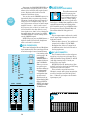
Film-Tech
The information contained in this Adobe Acrobat pdf
file is provided at your own risk and good judgment.
These manuals are designed to facilitate the
exchange of information related to cinema
projection and film handling, with no warranties nor
obligations from the authors, for qualified field
service engineers.
If you are not a qualified technician, please make no
adjuatments to anything you may read about in these
Adobe manual downloads
www.film-tech.com
CR-1604 OWNER’S MANUAL
–10 •
–10 •
–10 •
–10 •
–10 •
–10 •
–10 •
–10 •
–10 •
–10 •
–10
–10
•
+4
–25
U
MAINS
+4
–25
U
16
+4
–25
U
15
+4
–25
U
14
+4
–25
U
13
+4
–25
U
12
+4
–25
U
11
+4
–25
U
10
+4
–25
U
9
+4
–25
U
8
+4
U
7
+4
U
–10
•
–40
+4
–10
•
–40
U
5
+4
–10
•
–40
U
4
+4
SENSITIVITY
ADD 10dB FOR
MIC INPUTS
•
–40
U
3
+4
U
2
–40
1
PHANTOM
+48V
UNBALANCED LINE INPUTS
BAL MAIN OUT
–10
•
–40
6
MONO
AUX OUTPUTS
ALT 3/4 OUT BUSS INSERT
BALANCED/UNBALANCED LINE INPUTS
AUX RETURNS
CHANNEL ACCESS
TIP=OUT
LOW Z BALANCED MICROPHONE INPUTS
RING=IN
6
5
4
3
2
1
L
LEFT
1
2
3
LEFT
LEFT
4
5
6
RIGHT
RIGHT
1
2
3
4
1
2
3
4
5
6
7
8
R
MONITOR
RIGHT
1
2
3
4
5
6
7
8
9
10
11
12
14
13
15
16
PHANTOM
MAINS
CR1604 16 CHANNEL MIC/LINE MIXER
LAMP 12 VAC
AUX
AUX
U
AUX
U
AUX
U
AUX
U
AUX
U
AUX
U
AUX
U
AUX
U
AUX
U
AUX
U
AUX
U
AUX
U
AUX
U
AUX
U
STEREO AUX RETURNS
AUX
U
U
U
1
1
1
1
1
1
1
1
1
1
1
1
1
1
1
1
00 +15
MON
00 +15
MON
00 +15
MON
00 +15
MON
00 +15
MON
00 +15
MON
00 +15
MON
00 +15
MON
00 +15
MON
00 +15
MON
00 +15
MON
00 +15
MON
00 +15
MON
00 +15
MON
00 +15
MON
00 +15
MON
U
U
2
U
2
00
2
+15
U
3
00
5
00
4
00
6
00
+15
00
5
4
00
6
00
+15
0
4
00
6
00
+15
4
00
6
00
+15
4
00
6
00
+15
4
00
6
00
+15
4
00
6
00
+15
4
00
6
00
+15
4
00
6
00
+15
4
00
6
00
+15
4
00
6
00
+15
4
+15
6
00
+15
4
6
00
+15
4
+15
+15
–15 +15
–15 +15
–15 +15
–15 +15
–15 +15
–15 +15
–15 +15
–15 +15
–15 +15
–15 +15
–15 +15
–15 +15
–15 +15
–15 +15
–15 +15
0
0
0
0
0
0
0
0
0
0
0
0
0
0
0
0
MID
MID
MID
MID
MID
MID
MID
MID
MID
MID
MID
MID
MID
MID
R
MONO
4
L
C
4
AUX
SOLO
4
00
+20
L
R
BALANCE
HI
–15 +15
MID
+20
LEVEL
0
HI
3
C
U
5/6
SHIFT
0
HI
2
R
3
00
6
00
L
3
+15
U
4
+20
U
5
00
6
00
R
C
2
00
+15
U
3
+15
U
5/6
SHIFT
0
HI
00
5
00
1
L
2
+15
U
3
+15
U
5/6
SHIFT
0
HI
5
00
4
00
+20
U
2
+15
U
3
+15
U
5/6
SHIFT
0
HI
5
00
6
00
00
1
00
U
2
+15
U
3
+15
U
5/6
SHIFT
0
HI
00
5
U
2
+15
U
3
+15
U
5/6
SHIFT
0
HI
00
5
U
2
+15
U
3
+15
U
5/6
SHIFT
0
HI
00
5
U
2
+15
U
3
+15
U
5/6
SHIFT
0
HI
00
5
U
2
+15
U
3
+15
U
5/6
SHIFT
0
HI
00
5
U
2
+15
U
3
+15
U
5/6
SHIFT
0
HI
00
5
U
2
+15
U
3
+15
U
5/6
SHIFT
0
HI
00
5
U
2
+15
U
3
+15
U
5/6
SHIFT
0
HI
00
5
U
2
+15
U
3
+15
U
5/6
SHIFT
0
HI
00
5
U
2
+15
U
3
+15
U
5/6
SHIFT
0
HI
00
5
U
2
+15
U
3
+15
U
5/6
SHIFT
U
2
+15
U
3
+15
U
5/6
SHIFT
U
C
1
CR1604
16 CHANNEL MIC/LINE MIXER
MID
CLIP
+8
–12 +12
0
LO
–12 +12
0
LO
–12 +12
0
LO
–12 +12
0
LO
–12 +12
0
LO
–12 +12
0
LO
–12 +12
0
LO
–12 +12
0
LO
–12 +12
0
LO
–12 +12
0
LO
–12 +12
0
LO
–12 +12
0
LO
–12 +12
0
LO
–12 +12
0
LO
–12 +12
0
LO
–12 +12
0
LO
–15 +15
–15 +15
–15 +15
–15 +15
–15 +15
–15 +15
–15 +15
–15 +15
–15 +15
–15 +15
–15 +15
–15 +15
–15 +15
–15 +15
–15 +15
–15 +15
EQ
EQ
EQ
EQ
EQ
EQ
EQ
EQ
EQ
EQ
EQ
EQ
EQ
EQ
EQ
EQ
0
0
0
0
0
0
0
0
0
0
0
0
0
0
0
0
ALT PREVIEW
+4
+2
0
MAIN OUTPUT
MUTE
-4
-8
SOLO
TO
MAIN
-12
-16
-20
L
R
L
PAN
R
L
PAN
R
L
PAN
R
L
PAN
R
L
PAN
R
L
PAN
R
L
PAN
R
L
PAN
R
L
PAN
R
L
PAN
R
L
PAN
R
L
PAN
R
L
PAN
R
L
PAN
R
L
PAN
SOLO
SOLO
SOLO
SOLO
SOLO
SOLO
SOLO
SOLO
SOLO
SOLO
SOLO
SOLO
SOLO
SOLO
SOLO
1
2
3
4
5
6
7
8
9
10
11
12
13
14
15
16
MUTE
MUTE
MUTE
MUTE
MUTE
MUTE
MUTE
MUTE
MUTE
MUTE
MUTE
MUTE
MUTE
MUTE
MUTE
MUTE
ALT 3/4
ALT 3/4
ALT 3/4
ALT 3/4
ALT 3/4
ALT 3/4
ALT 3/4
ALT 3/4
ALT 3/4
ALT 3/4
ALT 3/4
ALT 3/4
ALT 3/4
ALT 3/4
R
POWER
PAN
SOLO
ALT 3/4
SOLO
LEVEL
ALT 3/4
1/LEFT
OL
OL
OL
OL
OL
OL
OL
OL
OL
OL
OL
OL
OL
OL
OL
OL
+20
+ 20
+20
+20
+20
+20
+20
+20
+20
+20
+20
+20
+20
+20
+20
+20
U
U
U
U
U
U
U
U
U
U
U
U
U
U
U
U
00
00
00
00
00
00
00
00
00
00
00
00
00
00
00
00
1
2/RIGHT
LEVEL
SOLO/PHONES
+10
U
00
00
CAUTION
AVIS
RISK OF ELECTRIC SHOCK
DO NOT OPEN
RISQUE DE CHOC ELECTRIQUE
NE PAS OUVRIR
CAUTION: TO REDUCE THE RISK OF ELECTRIC SHOCK
DO NOT REMOVE COVER (OR BACK)
NO USER-SERVICEABLE PARTS INSIDE
REFER SERVICING TO QUALIFIED PERSONNEL
ATTENTION: POUR EVITER LES RISQUES DE CHOC
ELECTRIQUE, NE PAS ENLEVER LE COUVERCLE. AUCUN
ENTRETIEN DE PIECES INTERIEURES PAR L'USAGER. CONFIER
L'ENTRETIEN AU PERSONNEL QUALIFIE.
AVIS: POUR EVITER LES RISQUES D'INCENDIE OU
D'ELECTROCUTION, N'EXPOSEZ PAS CET ARTICLE
A LA PLUIE OU A L'HUMIDITE
The lightning flash with arrowhead symbol within an equilateral
triangle is intended to alert the user to the presence of uninsulated
"dangerous voltage" within the product's enclosure, that may be
of sufficient magnitude to constitute a risk of electric shock to persons.
Le symbole éclair avec point de flèche à l'intérieur d'un triangle
équilatéral est utilisé pour alerter l'utilisateur de la présence à
l'intérieur du coffret de "voltage dangereux" non isolé d'ampleur
suffisante pour constituer un risque d'éléctrocution.
The exclamation point within an equilateral triangle is intended to
alert the user of the presence of important operating and maintenance
(servicing) instructions in the literature accompanying the appliance.
Le point d'exclamation à l'intérieur d'un triangle équilatéral est
employé pour alerter les utilisateurs de la présence d'instructions
importantes pour le fonctionnement et l'entretien (service) dans le
livret d'instruction accompagnant l'appareil.
SAFETY INSTRUCTIONS
1. Read Instructions — All the safety and operation
instructions should be read before the CR-1604 is operated.
2. Retain Instructions and Packaging — The safety and
operating instructions should be kept for future reference. Also
keep the box and end caps, in case the unit needs to be
returned for service.
3. Heed Warnings — All warnings on the CR-1604 and in
these operating instructions should be followed.
4. Follow Instructions — All operating and other instructions
should be followed.
5. Water and Moisture — The CR-1604 should not be used
near water — for example, near a bathtub, washbowl,
kitchen sink, laundry tub, in a wet basement, near a
swimming pool, swamp or salivating St. Bernard dog, etc.
6. Heat — The CR-1604 should be situated away from heat
sources such as radiators, or other devices which produce
heat.
7. Power Sources — The CR-1604 should be connected to a
power source only of the type described in these operation
instructions or as marked on the CR-1604.
8. Power Cord Protection — Power supply cords should be
routed so that they are not likely to be walked upon or
pinched by items placed upon or against them, paying
particular attention to cords at plugs, convenience receptacles,
and the point where they exit the CR-1604.
©1995 Mackie Designs™. All rights reserved.
Printed in the USA.
V 4.1 2/95, Part No. 820-001-00
2
9. Object and Liquid Entry — Care should be taken so that
objects do not fall into and liquids are not spilled into the
inside of the CR-1604.
10. Damage Requiring Service — The CR-1604 should be
serviced only by qualified service personnel when:
A. Objects have fallen onto, or liquid has spilled into the
CR-1604; or
B. The CR-1604 has been exposed to rain; or
C. The CR-1604 does not appear to operate
normally or exhibits a marked change in performance; or
D The CR-1604 has been dropped, or its chassis damaged.
11. Servicing — The user should not attempt to service the
CR-1604 beyond those means described in this operating
manual. All other servicing should be referred to the Mackie
Service Department. See page 21.
12. To prevent electric shock, do not use this polarized plug
with an extension cord, receptacle or other outlet unless the
blades can be fully inserted to prevent blade exposure.
Pour préevenir les chocs électriques ne pas utiliser cette fiche
polariseé avec un prolongateur, un prise de courant ou une
autre sortie de courant, sauf si les lames peuvent être insérées
à fond sans laisser aucune pariie à découvert.
13. Grounding or Polarization — Precautions should be
taken so that the grounding or polarization means of the
CR-1604 is not defeated.
This apparatus does not exceed the Class A/Class B
(whichever is applicable) limits for radio noise emissions from
digital apparatus as set out in the radio interference
regulations of the Canadian Department of Communications.
ATTENTION —Le présent appareil numérique n’émet pas de
bruits radioélectriques dépassant las limites applicables aux
appareils numériques de class A/de class B (selon le cas)
prescrites dans le règlement sur le brouillage radioélectrique
édicté par les ministere des communications du Canada.
WARNING — To reduce the risk of fire or electric shock, do
not expose this appliance to rain or moisture.
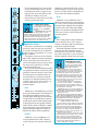
Thank you!!
There are a lot of makes and models of
mixers out there today, all competing for your
hard earned dough... but you have voted with
your wallet for the folks in Woodinville who
specialize in mixers.
And you are in good company !! The
CR-1604 is the compact mixer of choice for
some of the world’s top performing groups,
studio players, producers and soundtrack
composers. Even when they could buy anything they wanted, they chose the CR-1604. So
congratulations on joining the other
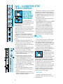
IF YOU IGNORE
MANUALS OR ARE JUST
HOT TO GET STARTED…
Please at least read the sections marked
with these two icons:
Our
VERY IMPORTANT
QU
ICK
ST
AR
T
Engineering
Manager
thinks this
looks like a
bomb. But
actually it’s a
genuine Buck
Rogers-style
space ship.
A CLOSER LOOK
They cover information that is absolutely
critical or is unique to the CR-1604. But it’s
still a good idea to read the whole manual
through at some point. We worked and slaved
to make this manual readable, understandable and informative and it’s bound to have a
few nifty nuggets of knowledge you haven’t
picked up from the school of hard nox.
In particular, sections
marked with A CLOSER
LOOK icon include indepth information...or at
least our own opinions.
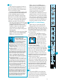
DESCRIPTION OF CONTROLS
BEGINS ON PG. 4
CONTROLS
& FEATURES
INPUT/OUTPUT “POD”
SECTION DESCRIPTION, PG. 11
INPUT
OUTPUT
POD
CONNECTION TIPS &
HOOKUP , PG. 15
HOOK
UP
DETAILED LEVEL-SETTING
PROCEDURE, PG. 19
LEVEL
SETTING
STEPS
POD ROTATION INSTRUCTIONS
PG. 20
CHANGING
THE POD
SERVICE, BLOCK DIAGRAM,
AND SPECS PG. 21-26
discerning musicians/recordists who have
found in this product the quality and performance that has long been considered
unattainable in this class and price range.
Okay, enough stroking. Time to dig in!
There are only two things that we ask:
Read this manual. Sounds obvious, but in all
the excitement that goes along with the purchase of a new piece of gear the new owner
often neglects to become as familiar as they
should with the product, and as a result
runs the risk of missing out on many of the cool
features and convenience that it can offer.
If this is your first pro-mixer, please flip
through the whole book. If you’re a seasoned
pro, at least read the sections with “QUICK
START” or “VERY IMPORTANT” icons next to
them. (However, we’ve found that truly experienced engineers usually read their owner’s
manuals cover-to-cover anyway… so they can
continue to make those big bucks.)
The following chapters will take you on a
guided tour of your new mixer and explain
the inner workings of each control, as well as
how it relates to the rest of the mixer and
your particular application.
3
TECH
STUFF
AUX
U
1
VERY IMPORTANT
00 +15
MON
U
2
00
+15
U
3
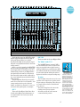
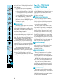
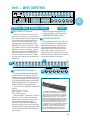
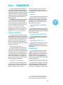
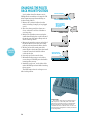
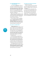
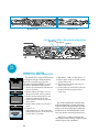
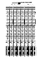
Part1— A GUIDED TOUR OF THE
CR-1604’S CONTROLS
All the knobs and buttons on the CR-1604’s
IMPORTANT front panel can be broken down into sixteen
input modules (channel strips) plus
SENSITIVITY identical
one Master Output section that’s divided into
Return and General Output sections (see
ADJUSTMENT Aux
1
QU
nifty
diagram at right).
ICK
Each input channel strip can be divided
PROCEDURE
5
into four specific sections:
To fully achieve the
• The AUX SENDs, with knobs color-coded RED
CR-1604’s impressive noise
4
6
and headroom specs, you should “tune” chan- • EQUALIZATION, color-coded BLUE
• PAN control, color-coded black, and
00 +15
nel sensitivity of each channel to your
5/6
• the channel LEVEL CONTROL faders
particular setup.
SHIFT
Can
you
run
the
mixer
without
this
adjust0
All modern mixing boards utilize some
HI
ment? Sure. Chances are that you’ll get pretty variation of this input module arrangement.
good sound. But take a moment to adjust
Once you’ve mastered the CR-1604’s input
–15 +15
things properly and you’ll get excellent sound. module layout, you should feel ready to take
0
MID
After all, it’s your music.
on that old 132-channel Neve mixing desk
Because we really want you to make this
gathering dust in your Aunt Hattie’s garage.
adjustment, we’ve included a slightly more
–12 +12
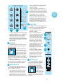
detailed description of the process on page 19. 1 AUX SENDS
0
LO
The basic procedure for adjustment is as
AUX 1, 2, 3 & 4
follows.
These controls are used to send the signal
–15 +15
A. Set EQ controls approximately the way
out to outboard parallel effects processors
EQ
they’ll be used for that channel. If you don’t
such as reverbs and delays. You may also use
know in advance, just set them flat .
an Aux Send to create a separate monitor mix
B. Turn the channel’s PAN control all the way for stage monitors or headphone cues or gento either the right or left.
erate separate mixes for recording.
C. Set Channel Fader to Unity (center detent).
There are a total of seven Aux Sends on
A
each
CR-1604 channel strip. A combination of
D.
Turn
the
channel’s
SENSITIVITY
control
9 D
four may be used at the same time.
fully counter clockwise (+4 UNITY).
NOTE: All of the
15
E. Press the channel’s SOLO button and the
CR-1604’s Aux sends have
SOLO TO MAIN button over on the main
a very wide range of gain.
9
output section of the mixer.
The first half of the
F. Play through the channel at the same
EQ
control’s rotation reaches
15
volume and intensity that the channel is
F
B
from
the
off
position
to Unity Gain (0dB).
going to handle during use. Turn the
CLIP
PAN
This
half
of
the
control’s
range corresponds to
channel’s SENSITIVITY control clockwise
+8
ESOLO
the
full
range
of
a
conventional
mixer. The
9
until the level on the CR-1604 meter (left
+4
MUTE
second
half
of
the
control’s
rotation
provides
or right side, depending on which way you
+2
you
with
even
more
gain,
from
Unity
to
have the PAN set) reads around OdB.
0
+15dB. For example, when you want a sound
G. Set the EQ the way you think you’ll want it,
-4
super-“wet” (mostly reverb), the extra gain althen repeat step F.
C
lows you to bring the channel fader down
-8
H. Turn the channel’s SOLO button off and
(and the send way up) so that the sound is
-12
return the PAN control to center detent
composed of predominantly reverb return
-16
position.
with just a touch of “dry” signal.
-20
I. Repeat this procedure for each channel,
AUX 1/MON
using the appropriate kind of source which
will be used with that channel.
This particular Aux control could be
viewed as the King of Sends, because of its
varied functions.
00
0
ST
AR
T
+15
U
HI
–10 •
–15 +15
MID
+4
U
–40
VERY IMPORTANT
0
–12 +12
0
LO
–10 •
–15 +15
+4
0
L
U
–40
R
ALT 3/4
OL
+20
U
00
4
1
2
3
4
5
6
7
8
9
10
11
12
14
13
15
16
PHANTOM
MAINS
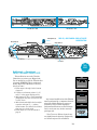
CONTROLS
& FEATURES
CR1604 16 CHANNEL MIC/LINE MIXER
INPUT/OUTPUT “POD”
LAMP 12 VAC
AUX
AUX
U
AUX
U
AUX
U
AUX
U
AUX
U
AUX
U
AUX
U
AUX
U
AUX
U
AUX
U
AUX
U
AUX
U
AUX
U
AUX
U
STEREO AUX RETURNS
AUX
U
U
U
1
1
1
1
1
1
1
1
1
1
1
1
1
1
1
1
00 +15
MON
00 +15
MON
00 +15
MON
00 +15
MON
00 +15
MON
00 +15
MON
00 +15
MON
00 +15
MON
00 +15
MON
00 +15
MON
00 +15
MON
00 +15
MON
00 +15
MON
00 +15
MON
00 +15
MON
00 +15
MON
U
U
2
U
2
00
+15
U
3
00
5
00
6
00
+15
+15
U
4
+15
5/6
SHIFT
0
4
00
6
00
+15
4
00
6
00
+15
4
+15
0
HI
4
00
6
00
+15
5/6
SHIFT
4
+15
0
HI
4
00
6
00
+15
5/6
SHIFT
4
00
6
00
+15
4
6
00
+15
5/6
SHIFT
0
HI
00
4
+15
4
+15
6
00
+15
6
00
+15
4
6
+15
+15
—15 +15
—15 +15
—15 +15
—15 +15
—15 +15
—15 +15
—15 +15
—15 +15
—15 +15
—15 +15
—15 +15
—15 +15
—15 +15
—15 +15
—15 +15
0
0
0
0
0
0
0
0
0
0
0
0
0
0
0
0
—12 +12
0
LO
MID
—12 +12
0
LO
MID
—12 +12
0
LO
MID
—12 +12
0
LO
MID
MID
MID
MID
MID
MID
CHANNEL STRIPS
—12 +12
0
LO
—12 +12
0
LO
—12 +12
0
LO
—12 +12
0
LO
—12 +12
0
LO
—12 +12
0
LO
MID
MID
MID
MID
MID
—12 +12
0
LO
—12 +12
0
LO
—12 +12
0
LO
—12 +12
0
LO
4
4
00
+20
L
BALANCE
CLIP
+4
—12 +12
0
LO
+2
0
-4
—15 +15
—15 +15
—15 +15
—15 +15
—15 +15
—15 +15
—15 +15
—15 +15
—15 +15
—15 +15
—15 +15
—15 +15
—15 +15
—15 +15
—15 +15
EQ
EQ
EQ
EQ
EQ
EQ
EQ
EQ
EQ
EQ
EQ
EQ
EQ
EQ
EQ
EQ
0
0
0
0
0
0
0
0
0
0
0
0
0
0
0
0
-8
-12
-16
-20
L
R
L
PAN
R
L
PAN
R
L
PAN
R
L
PAN
R
L
PAN
R
L
PAN
R
L
PAN
R
L
PAN
R
L
PAN
R
L
PAN
R
L
PAN
R
L
PAN
R
L
PAN
R
L
PAN
R
L
PAN
SOLO
SOLO
SOLO
SOLO
SOLO
SOLO
SOLO
SOLO
SOLO
SOLO
SOLO
SOLO
SOLO
SOLO
SOLO
1
2
3
4
5
6
7
8
9
10
11
12
13
14
15
16
MUTE
MUTE
MUTE
MUTE
MUTE
MUTE
MUTE
MUTE
MUTE
MUTE
MUTE
MUTE
MUTE
MUTE
MUTE
MUTE
ALT 3/4
ALT 3/4
ALT 3/4
ALT 3/4
ALT 3/4
ALT 3/4
ALT 3/4
ALT 3/4
ALT 3/4
ALT 3/4
ALT 3/4
ALT 3/4
ALT 3/4
ALT 3/4
R
ALT 3/4
ALT 3/4
1/LEFT
OL
OL
OL
OL
OL
OL
OL
OL
OL
OL
OL
OL
OL
OL
OL
+20
+ 20
+20
+20
+20
+20
+20
+20
+20
+20
+20
+20
+20
+20
+20
+20
U
U
U
U
U
U
U
U
U
U
U
U
U
U
U
U
00
00
00
00
00
00
00
00
00
00
00
00
00
00
00
00
This send is Post EQ and Post Fader. Since
it’s affected by EQ and gain adjustments, we
recommend that it be used as your main
reverb send.
SOLO
TO
MAIN
2/RIGHT
LEVEL
SOLO/PHONES
+10
U
00
00
AUX 3 & 4
These two sends are also post-EQ/post-Fader.
The “hidden” sends: 5 & 6
The 5/6 SHIFT button “converts” AUX 3
and 4 to AUX Sends 5 and 6. In other words,
after you press this button, signal is sent to
AUX 5 and AUX 6 but controlled by the AUX 3
and 4 Knobs. We did this to add the flexibility
of extra sends without making the mixer so
big that it looks like an airport landing strip.
To review
The CR-1604s Aux sends are used to route
a portion of the signal out to another source
for processing or sub-mixing. They allow you
to control how much effect is mixed with
each channel.
• All channel strips have four Aux sends
feeding a total of seven outputs.
• All sends are fully off in the extreme
counterclockwise position.
5
A CLOSER LOOK
AUX 2
MAIN OUTPUT
MUTE
SOLO
LEVEL
OL
Send 1 may be routed to AUX OUT 1 which
taps the signal downstream from the EQ circuitry and Channel Fader (we call this
Post-Fader/Post-EQ, meaning that the signal
will reflect any adjustments made to the fader
or EQ controls.)
Send 1 can also be routed to the MONITOR
OUT by pressing the MON button. This signal
is intercepted ahead of the EQ circuitry and
Channel Fader (known as pre-EQ/pre-Fader…
the signal will be the same as it was when it
first entered the input module, unaffected by
the control adjustments made with the EQ or
fader controls).
This arrangement allows for two separate
sends. You can use Send 1 on Channels 1–6 as
a stage monitor mix for vocals (with mic
inputs), and Send 1 on Channels 7–16 as a reverb send (with synth inputs, for example).
ALT PREVIEW
POWER
PAN
SOLO
AUX
SOLO
R
CR1604
16 CHANNEL MIC/LINE MIXER
MID
—15 +15
MONO
C
+8
—12 +12
0
LO
R
4
L
HI
—15 +15
MID
+20
LEVEL
0
HI
3
C
U
5/6
SHIFT
0
HI
2
R
3
00
6
00
L
3
+15
U
4
+20
U
5
00
5/6
SHIFT
0
HI
R
C
2
00
+15
U
3
+15
U
00
1
L
2
00
5
00
5/6
SHIFT
0
HI
4
+15
U
3
+15
U
+20
U
2
00
5
00
5/6
SHIFT
0
HI
+15
U
4
+15
U
3
00
U
2
00
5
00
6
00
+15
U
3
+15
U
5/6
SHIFT
0
HI
00
5
U
2
+15
U
3
+15
U
U
2
00
5
00
6
00
+15
U
3
+15
U
5/6
SHIFT
0
HI
00
5
U
2
+15
U
3
+15
U
5/6
SHIFT
0
HI
00
5
U
2
+15
U
3
+15
U
U
2
00
5
00
6
00
+15
U
3
+15
U
5/6
SHIFT
0
HI
00
5
U
2
+15
U
3
+15
U
U
2
00
5
00
6
00
+15
U
3
+15
U
5/6
SHIFT
0
HI
00
5
U
2
+15
U
3
+15
U
5/6
SHIFT
0
HI
00
5
U
2
+15
U
3
+15
U
5/6
SHIFT
0
HI
00
5
00
6
00
+15
U
3
U
2
1
OUTPUT SECTION
4
00
5/6
SHIFT
00
5
U
2
+15
U
3
+15
U
U
2
C
1
WUTZA DEEE-TENT?
Occasionally in this
manual you will see a
reference to detents. A
detent is a simple but
effective control feature
that will aid in easy resetting of your mixers
controls. It’s simply a
notch in the movement
of the control component, which determines a
neutral setting, such as
Unity on faders or center
on the PAN control. This
way you’re either in de
tent or out of de tent, as
we say when camping up
here in the Northwest.
• We recommend going into a stereo reverb
in mono and returning in stereo. We have
found that most “stereo” reverbs’ second
input just ties up an extra AUX send and
adds little or nothing to the sound.
• All send buses are isolated from each other
and have separate mix amps.
AUX
U
1
00 +15
MON
U
2
AUX SENDS AND LIVE MIXING
When using microphones in a
live performance, we recommend
that AUX 1 be set to MONITOR
position.
In MONITOR mode, the signal
is taken ahead of the EQ and Fader circuitry.
When in AUX mode the signal will be taken downstream of the EQ and Fader circuitry. Remember
that this means that the signal will reflect any
changes brought about by settings made to EQ and
channel fader controls, but still can be used.
+15
U
3
A CLOSER LOOK
00
5
00
+15
U
4
6
00
+15
5/6
SHIFT
0
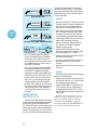
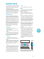
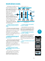
2 Equalization Controls
HI
–15 +15
0
MID
–12 +12
0
LO
2
EQ
0
3
L
R
PAN
SOLO
1
MUTE
ALT 3/4
OL
+20
U
00
EQ HI
15dB boost or cut at 12kHz. There is no effect
at the center detent position. This shelving control will affect the higher frequencies of the
incoming signal. By shelving, we mean that the
circuitry boosts or cuts all frequencies past the
specified point, instead of just creating a bump
or dip in response the way a graphic equalizer
would. Use this control to add sizzle to cymbals
and vocals and give a sense of transparency or
edge to keyboards and guitars. It can also be
turned down a little to reduce sssssibilance.
EQ MID
12dB boost or cut at 2.5 kHz with a 3.3
octave bandwidth (this is NOT a shelving
control). Because the majority of musical in6
EQ LO
15dB boost or cut at 80Hz. This control
affects the lower frequencies of your input signal. It can be used to put punch in bass drums,
bass guitar, fatten synth patches and add bottom end to male vocals. Cutting the LO EQ
slightly can do wonders for muddy tracks and
boomy room acoustics as well as helping fix
poppy microphones.
3 PAN
This control positions a signal within the
stereo sound field. Also a way to “assign” a
channel to just left or right for sub-grouping
to the mono or ALT-3/4 outputs.
The Mackie CR-1604 incorporates constantpower pan pots which maintain constant
acoustic power as you move the channel’s signal to left or right. This is a way cool feature
which is explained in detail on the next page.
LECTURE TIME:
CONCERNING EQUALIZATION
MODERATION: Proper EQ
can focus a mix. Improper EQ
can cause distortion. Too much
EQ results in mix mush.
The best EQ is none at all. In other words, in
live recording situations, you should start by selecting the right mic, positioning it correctly and
recording in the right acoustic environment.
When mixing direct inputs, time spent on tweaking with the synth patch, boldly going where the
tone module preset hasn’t been before or adjusting the instrument’s own tone controls beats the
heck out of “saving it in the mix.”
Save the CR-1604’s EQ for solving problems
you can’t work out in advance — particularly in
live PA situations (where anything can happen
and probably will) or final mix where you’re going
for a particular overall sound.
EQ POINTS: Some of you may have probably noticed that theCR-1604 does not have it’s EQ points in
the usual (Yawn) “standard” frequency locations.
Why? You may ask.
Well, the story goes that sometime in the Sixties,
“Zoltan” (Bureaucratic High Moron from the Drumless
planet of Vocal Frustration) descended upon the mixing board designers in Countries to the East and
proclaimed the proper EQ points for mixers:
“10kHz for HF and 100Hz for LF”
We can’t figure out why. 100Hz is too high and
10kHz is too low. They might be holdovers from really ancient mixing boards or radio equipment
back in the days when recording bandwidth was a
lot narrower. It’s irrational and not founded on
any particular acoustic or musical principle...but
then, Zoltan never visited us.
Being musicians ourselves (and having cursed
Zoltanesque EQ in other boards for years), we decided to start from scratch and determine the
points which sounded best from a musical standpoint. It goes without saying that Zoltan was not
pleased with the Rebels From The Rainforest.
But we trust that you will be.
A CLOSER LOOK
–15 +15
These three controls offer you a surprising
amount of control over the sonic personality
of your mix (although they are not intended
to take the place of a parametric or 1/3-octave
graphic equalizer).
Through the creative use of the CR-1604’s
EQ controls, samplers and other instruments
can be contoured to better reflect the real
world sound signature they are trying to emulate, mixes can be punched up, vocalists
rescued from obscurity, etc.
We’ve carefully selected different points for
our equalization and have used circuity which
provides an extremely “musical” effect. Some
heavy-duty pros have complemented us on
how useful they are. So before you immediately plug in an outboard equalizer, give the
controls a chance. If all you’ve used are conventional small mixers, you’re in for a
pleasant surprise.
formation is contained in this range, a little
midrange EQ goes a long way. It can increase
presence of a mix, enhance intelligibility of a
vocal or back off a strident instrument.
4 SOLO
• While a channel is in SOLO mode, its
signal level is sent to the CR-1604 Level
Meters in the Master Output section so
you can observe its working level. This
allows level setting for each individual
channel using just one meter pair.
• The SOLO indicator LED will also blink to
remind you that you are in the solo mode.
We designed it to be so obnoxiously bright
that you can get a suntan from it if you get
too close for too long. If you’ve ever used a
board with a tiny, obscure SOLO light, you
know why we made ours large and rude.
nifto-features, we wanted the mixer to perform to
the demanding standards of higher priced gear, so
that it could be used for professional recording,
broadcasting, and film sound where the need for
true panning integrity is often an unavoidable reality. And low and behold, the CR-1604 IS being
used extensively by Hollywood pros for TV and
film sound tracks. End of commercial.
U
1
00 +15
MON
U
2
6 OL
The OverLoad LED is a visual indicator
that warns you when you’re overdriving the
channel. Because it monitors multiple points
in the channel’s circuitry, it detects more
than just input overload.
7
00
+15
U
00
+15
U
3
5
4
6
00
+15
5/6
SHIFT
0
HI
–15 +15
0
MID
–12 +12
0
LO
VERY IMPORTANT
A CLOSER LOOK
This control does just what it’s name implies. By pushing the SOLO button, you can
listen in on only that channel while muting
the rest of the mixer’s output.
In order to make this function really useful,
we have designed the CR-1604’s SOLO section
to allow for multiple inputs to be soloed
together while retaining the original stereo
placement of each channel in the mix. This
feature is not often found outside of large mixing consoles, even though it adds significant
application potential to the solo function.
• The effect of this button follows the setting 5 MUTE-ALT 3/4 (3rd & 4th buses)
of the SOLO TO MAIN button (i.e. if SOLO
Think of this as a “mute button PLUS.”
TO MAIN is pressed IN, the main and
First, it works in the conventional way:
headphone outputs are replaced with the
push MUTE and that channel goes away, just
soloed signals. If it’s left in the OUT
like you’d expect. But, we reasoned, why send
position, only the headphones will get the
the channel’s output into the ozone when it
soloed signals).
could go someplace useful? Such as another
IMPORTANT: The master level of the SOLO
set of output buses.
signal is controlled by the HEADPHONE/
So when you press MUTE, the signal is
SOLO fader, not the master faders.
reassigned to the ALT 3/LEFT and 4/RIGHT
stereo outputs.
WHAT CONSTANT POWER
NOTE: There is no masPAN POTS MEAN TO YOU
ter
level control for the
When you sit between a pair
ALT-3/4 buses. With the
of monitors and pan from side to
side, the apparent loudness at
channel set at Unity, the
your ears should stay the same
signal will come out at
no matter where the source is positioned.
The CR-1604’s constant power pan pots are so
Unity gain just as if you had a master fader at
named because they incorporate special circuitry
the center detent position.
that maintains consistent acoustic power while
panning center to side.
There are lot of possibilities via the ALT
When the input module is set to the center de3/4 buses with the channel fader set at Unity.
tent, what you will hear is equal amounts of both
left and right outputs.
Especially combined with the ALT PREVIEW
When the module is panned away from center,
button over in the CR-1604’s Master Output
you will begin to hear only one side. The side that
section. For example, you can create two
you are panning into must therefore grow louder to
make up for the loss of the other side. The effect is
stereo pairs for output to 4-track. Or bounce
a more realistic shift in dimensional perception
multiple tracks onto one or two more tracks.
(Ooooo… sounds pretty cosmic, doesn’t it? )
Here is an example of how stereo sound beOr preview a sound source that hasn’t been
haves in real life, why you would want to duplicate
introduced into the mix yet.
the same effect in your productions and how constant power pan pots help:
One of the most common applications for
Imagine that a sax player was standing in front
ALT
3/4 is for creating submixes from various
of you playing his horn. You get the same amount
of sound at both ears and your ear-brain processcombinations of channels. By panning one set
ing center sez, “This cat is right in front of me.”
of channels hard left and another hard right,
Now the sax player moves to the left. More sound
you can create two submixes (one from the
arrives at your left ear and your brain sez , “He’s
over on the left.” But the total amount of sound arLEFT ALT and one from the RIGHT ALT outriving at your ears is still the same.
put) that can be routed back into spare
Constant power pan pots do the same thing.
They move the sound, but don’t reduce the overall
channels on the board, or AUX returns. (See
amount of sound. Other small mixers don’t have
page 16 for more details.)
this feature. But like many other of the CR-1604’s
AUX
–15 +15
EQ
0
L
4
5
R
PAN
SOLO
1
MUTE
ALT 3/4
OL
+20
U
00
6
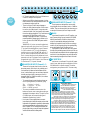
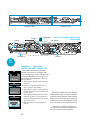
Part 2 — THE MAIN
OUTPUT SECTION
AUX
U
1
00 +15
MON
U
2
00
+15
U
3
5
00
+15
U
4
6
00
+15
5/6
SHIFT
0
HI
–15 +15
0
MID
–12 +12
0
LO
–15 +15
EQ
0
L
R
PAN
SOLO
1
MUTE
ALT 3/4
OL
+20
U
7
00
Basically, the OL lights should never blink.
If they do, you’re courting the potential of audible distortion.
• If you adjust the channel’s input SENSITIVITY too high and compensate by pulling
Now that you have become more familiar
the faders down, the OL light will still flash with the CR-1604’s channel strips, let’s move our
— even though you’re seeing conservative
guided tour on to the Master control center.
levels on the meters.
We will start at the top of the section with
• If you set SENSITIVITY properly but add a the Stereo Aux Returns.
LOT of EQ while mixing, you might also
8 STEREO AUX RETURNS LEVEL
trigger the OL indicator. In this case,
Located at the upper left of the Master
lowering the channel’s SENSITIVITY trim
Section,
these four controls set the overall
pot will keep from over driving the EQ,
level
for
signals
received via the four stereo
which may be clipping.
Aux Returns from whatever effects you’ve
7 CHANNEL FADER
connected from the Aux Sends.
As with the sends, these controls are deControls the overall output of the channel.
signed to handle a very wide range of signal
All of the AUX SENDS with the exception of
levels (which is a good thing considering the
AUX 1/MON in Monitor mode are affected by
wildly varying output levels of many outboard
this control (AUX 1/MON in Monitor mode is
signal processors). Remember how the gain
not affected because it is placed upstream of
was divided on the Aux Send controls? The
the Fader and EQ, remember?)
Most mixer channel faders are labeled with same approach is used on these controls. The
arbitrary and confusing ranges of digits (such first half of the knob’s rotation operates from
off to Unity Gain (0dB) center position. The
as 1 thru 10) that don’t correspond to anysecond half of the rotation provides gain from
thing. This often leads to mis-adjustment, as
0dB up to 20dB gain which can be very useful
well as distortion, noise or all of the above.
for bringing the level of some low output efOn the CR-1604, proper gain settings are
fects up to professional operating levels.
facilitated by the click-detent Unity Setting
half way up the slider. When the channel’s in- 9 AUX RETURN BALANCE
put control has been adjusted properly, Unity
The four Aux Return Balance controls are
represents NO LOSS OR GAIN when panned
used
to control the left/right balance of each
left or right.
return’s
signal (just like on your stereo)
This means you have a known setting
within
the
main mix.
which is easily repeatable, even in the dark.
Because levels can be set properly from this
10 AUX RETURN MONO
reference point, you can achieve very high
These four buttons are used to combine
headroom and low noise at the same time.
And, unlike any other mixer, you have 20dB left and right Stereo Aux Return signals into a
monaural signal, which is then sent on in
MORE gain above Unity.
equal proportions to the left and right Master
Mix Buses.
NOTE: If all four Stereo Aux Returns are
set to mono, a total of 8 separate mono feeds
can be routed to the main mix.
If you are connecting an effects device
which only has a mono out, pressing the AUX
RETURN MONO button will route the effect
to both the Left and Right main buses.
11 AUX RETURN SOLO
This button is used to solo the four Aux Returns for more detailed scrutiny. This function is
the same as that of the Solo control on the
individual channel strips, except that it solos all
four AUX returns at the same time.
8
STEREO AUX RETURNS
U
1
C
1
00
+20
1
L
U
2
10
R
C
2
2
00
+20
L
U
3
R
4
3
00
+20
L
U
4
R
MONO
C
+20
14 SOLO TO MAIN
AUX
SOLO
4
00
3
C
down or click track in your headphones,
and then just before the down beat, UNmute the CR-1604.
• For live performance intermissions, use
the MAIN OUTPUT MUTE to kill hum and
noise from the room and prevent drunken
head bangers from mounting the stage and
screaming the name of a rival band.
• When recording at home and the telephone rings, hit the MAIN mute instead of
pulling down your main faders. Now you
can monitor that quality near field loudspeaker in your answering machine and
decide whether or not to SOLO the caller.
L
R
LEVEL
BALANCE
8
9
11
• The effect of this button follows the setting of
the SOLO TO MAIN button (i.e. if SOLO TO
MAIN is pressed IN, the phones and the
main output are replaced with the Aux
Return signals. If it’s left in the OUT position,
only the headphones will get the soloed Aux
Return signals).
12 ALT PREVIEW
This switch determines what happens when
you press channel or Aux Return SOLO buttons.
• IN — The CR-1604’s Main output is
interrupted whenever a Solo
button is activated.
• OUT — Only the Headphone
output is interrupted during solo
ALT PREVIEW
monitoring. This is great for live
work so that the sound person
can solo into his phones without
MAIN OUTPUT
affecting the main mix. Sorry,
MUTE
but this button is not effective
against poorly played or excesSOLO
TO
sively lengthy guitar solos. If the
MAIN
problem persists, consult a
physician or perhaps try the
MUTE-ALT 3/4 on the offending
player’s channel.
• In the studio, SOLO TO MAIN
can allow you to listen to your
solo channels through the same
LEVEL
speakers that you use for the
SOLO/PHONES
mixdown if you are using the
Main Outputs for your control
room monitoring.
12
13
VERY IMPORTANT
VERY IMPORTANT
This button allows all channels assigned
to the ALT 3/4 to be monitored through the
headphone output.
This can come in very
handy when you need to
hear a cue from one of the
tracks that is currently assigned to the ALT 3/4 Bus
(Muted). All the inputs that are currently assigned to the ALT 3/4 output can be heard
through your headphones when the ALT PREVIEW button is depressed.
15 HEADPHONE JACK
You can also use this feature to monitor a
The stereo PHONE jack will drive
second mix if you have decided to hook up a
any standard headphones. Walk-Persecond tape deck to the ALT 3/4 outputs.
son-type mini phones can also be
13 MAIN OUTPUT MUTE
used with an appropriate adaptor.
This button mutes the main stereo and
WARNING:
mono outputs of the CR-1604. All other outWhen we say the
puts are blissfully unaffected.
headphone amp is
loud, we’re not
• A useful application for this control is to
kidding. Even interhelp reduce perceived noise from your
mediate
levels
may
be unpleasantly
multitrack tape machine and musical
loud
with
some
headphones.
Be careinstruments prior to the start of the song.
ful,
please!
Mute the mixer while monitoring the count
14
15
00
9
INPUT
OUTPUT
POD
VERY IMPORTANT
Always turn the SOLO/PHONES LEVEL con- 17 1/LEFT 2/RIGHT
(MAIN OUTPUT LEVEL FADERS)
trol down before you put the phone on. Then
advance it for best levels with a typical sound
This gallant team stands
source. Engineers who fry their ears find
guard over your precious
themselves with short careers.
main output level. They preYou can also use the PHONES output to infer to be stationed below or
dependently drive a separate tape recorder,
at the “U” (Unity) setting.
PA system or studio monitor amp. Instead of
The outputs on the other end are capable of deusing a low-cost “headphone amp” chip, we
livering up to +28dBm. Many amplifiers or other
use a high-current version of our main output equipment inputs will go into clipping before
amplifier circuity — which is why it can rethat. Consult the specs on your amplifier/device.
ally clean out your cochlea if you crank it up
You may have to keep the CR-1604’s Main and
too far. But that’s also what makes it a very
Phone faders below the Unity gain level.
clean signal source that’s, in fact, identical to
the quality of the other outputs (see APPLI- 18 LEVEL
CATIONS GUIDE for various hookups which
This 10-segment meter reflects the “unbaluse the PHONES output).
anced” output signal strength at the left and
NOTE: When you press any SOLO button, a right main outputs.
slight click will be heard in the headphones
• When the meter shows “0”, the unbalanced
when a solo switch is activated.
output level is 0dBu (0.775 VAC RMS).
16 SOLO/PHONES LEVEL
• Remember that “balanced” output levels
are 6dB hotter than the level indicated on
This control adjusts the Solo and Headphone
the bar graph meter.
levels simultaneously. The control range is from
INPUT
OUTPUT
POD
off to loud enough to cause a frontal lobotomy
L BNC LAMP CONNECTOR
(see warning on the
The CR-1604 includes a socket and power
CLIP
previous page). Besupply for a 12-volt goose-neck lamp. We rec+8
ALT PREVIEW
cause SOLO/
ommend LittleLite lamps PN #12G or 12G-HI
+4
PHONES LEVEL is
+2
completely indepen- (with high-intensity bulb). Consult your
0
dealer for the gory details.
dent of the Master
MAIN OUTPUT
MUTE
-4
NOTE: When the CR-1604 has been “RotoFaders, you can use
-8
podded”
(pod jack to the front) the BNC lamp
it to preview your
SOLO
-12
connector
becomes inaccessable.
mix before fading up
TO
-16
MAIN
This
concludes
our guided tour of the
the main outputs.
-20
CR-1604’s
controls.
After a short intermission,
CAUTION: To
we
will
re-board
the
bus (HA! Get it? Pun?
avoid speaker damPOWER
bus......?
Oh
well.)
and
explore the CR-1604’s
age, this control
SOLO
input/output “pod.”
should never be set
LEVEL
higher than the Main
Output (1/LEFT 2/
RIGHT) level prior to
1/LEFT 2/RIGHT
LEVEL
activating the SOLO
SOLO/PHONES
TO MAIN button.
18
+10
17
16
1
2
3
4
5
6
7
8
9
10
11
12
13
CR1604 16 CHANNEL MIC/LINE MIXER
L
U
LAMP 12 VAC
AUX
AUX
U
00
AUX
U
AUX
U
AUX
U
AUX
U
AUX
U
AUX
U
AUX
U
AUX
U
AUX
U
U
1
1
1
1
1
1
1
1
1
1
1
00 +15
MON
00 +15
MON
00 +15
MON
00 +15
MON
00 +15
MON
00 +15
MON
00 +15
MON
00 +15
MON
00 +15
MON
00 +15
MON
00 +15
MON
00 +15
MON
U
2
U
2
00
+15
U
3
00
3
6
4
00
00
+15
5/6
SHIFT
+15
U
3
6
4
00
00
+15
+15
U
3
6
4
00
00
+15
+15
U
3
6
4
00
00
+15
+15
U
3
6
4
00
00
+15
+15
U
3
6
4
00
00
+15
+15
U
3
6
4
00
00
+15
+15
U
3
6
4
00
00
+15
+15
U
3
6
4
00
00
+15
+15
U
6
4
+15
U
00
00
+15
5/6
SHIFT
0
3
+15
U
3
6
4
+15
U
00
00
+15
5/6
SHIFT
0
2
00
5
+15
U
00
2
00
5
3
6
4
+15
U
00
+15
5/6
SHIFT
0
0
MO
U
2
00
5
1
U
2
00
5
+15
U
5/6
SHIFT
0
U
2
00
5
+15
U
5/6
SHIFT
0
U
2
00
5
+15
U
5/6
SHIFT
0
U
2
00
5
+15
U
5/6
SHIFT
0
U
2
00
5
+15
U
5/6
SHIFT
0
U
2
00
5
+15
U
5/6
SHIFT
0
U
2
00
5
+15
U
5/6
SHIFT
0
U
2
00
5
+15
U
5/6
SHIFT
0
U
2
00
5
+15
U
4
10
AUX
U
1
00 +15
MON
U
00
AUX
U
1
+15
U
3
6
4
+15
U
00
+15
5/6
SHIFT
0
5
5
SH
0
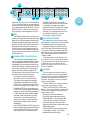
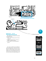
Part 3 — INPUT/OUTPUT POD
–10 •
–10 •
–10 •
–10 •
–10 •
–10 •
–10 •
–10 •
–10 •
–10 •
–10
–10
•
+4
U 16
MAINS
–25
+4
U 15
–25
+4
U 14
–25
+4
U 13
–25
+4
U 12
–25
+4
U 11
–25
+4
U 10
–25
+4
U
–25
+4
–25
U
9
+4
U
8
–25
+4
U
7
+4
U
–10
•
–40
+4
U
5
–10
•
–40
+4
U
4
MONO
AUX OUTPUTS
ALT 3/4 OUT BUSS INSERT
AUX RETURNS
+4
U
–40
4
TIP=OUT
1
5
2
3
LEFT
LEFT
1
2
3
4
1
2
3
4
4
3
2
4
5
6
RIGHT
RIGHT
OUTPUTS/SENDS
5
6
7
8
INPUTS
RETURNS/INSERTS
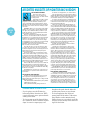
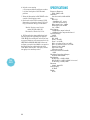
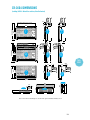
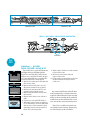
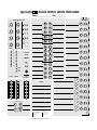
19 INPUT SENSITIVITY CONTROLS
• When using microphone XLR input jacks,
you will get 10dB more gain than what the
SENSITIVITY trim marking indicates.
The first set of items on our tour are the
sensitivity controls for the 16 input channels.
These knobs adjust the input sensitivity of the 21 PHANTOM POWER SWITCH
mic and line inputs so signals from the outWhat is Phantom Power? No, it’s not the arch
side world are brought into the mixer at
enemy of Captain America or anything like that.
optimum internal operating levels. INPUT
Most modern professional condenser mics are
SENSITIVITY controls for channels 1–6 have
up to 40dB of gain for line inputs and 50dB for equipped for Phantom Power, which lets the
mixer send DC power to the mic’s electronics
XLR inputs; controls for channels 7–16 have
25dB of gain. Note that all SENSITIVITY con- over the same wires that carry audio (hence
“phantom” since the DC voltage is “unseen” by dytrols are marked with a –10 setting. This is
namic and ribbon mics which don’t need external
the amount of gain needed to raise –10dBv
power and are unaffected by it anyway).
operating level equipment up to professional
+4dB levels.
–10 •
21
+4
U 16
–10 •
–40
SENSITIVITY
ADD 8dB FOR
MIC INPUTS
–40
4
+4
U 15
–10 •
–40
+4
U 14
–10 •
–40
+4
U 13
–10 •
–40
+4
U 12
–10 •
–40
+4
U 11
–10 •
–40
+4
U 10
–10 •
–40
U
19
–10 •
+4
–40
9
–10 •
+4
U
–40
8
–10
U
–10
•
+4
–40
7
+4
U
–10
•
–40
+4
U
6
–10
•
–40
+4
U
5
–40
4
–10
•
+4
U
–40
3
–10
•
+4
U
–40
2
•
+4
U
SENSITIVITY
ADD 8dB FOR
MIC INPUTS
–40
1
PHANTOM
UNBALANCED LINE INPUTS
BALANCED/UNBALANCED LINE INPUTS
LOW Z BALANCED MICROPHONE INPUTS
6
20 MICROPHONE INPUTS (Channels1–6)
We use true phantom-powered, balanced inputs just like the big, studio mega-consoles for
the same reason they do: This kind of circuit is excellent at rejecting hum and noise. You can plug
in any kind of professional microphone that has a
standard “XLR-type male” mic connector, an impedance of between 50 ohms and 600 ohms.
If you wire your own male XLR’s, connect them
like this:
Pin 2= Positive (+ or hot)
Pin 3 = Negative ( – or cold)
Pin 1 = Shield (ground)
Basically, Inputs 1–6 will handle any kind of
mic level you can toss at them. Professional
ribbon, dynamic and condenser mics will all
sound excellent through these inputs —
especially if you follow the Level Setting instructions on page 19. Lower-cost electret-type,
unbalanced mics should be plugged into Inputs
7–16 but will require additional gain and thus
not be as quiet.
1
INPUT
OUTPUT
POD
R
MONITOR
U
LOW Z BALANCED MICROPHONE INPUTS
RING=IN
L
RIGHT
•
+4
BALANCED/UNBALANCED LINE INPUTS
CHANNEL ACCESS
6
LEFT
–10
•
–40
4
PHANTOM
+48V
UNBALANCED LINE INPUTS
BAL MAIN OUT
–10
•
–40
6
5
4
3
2
1
20
NEED MORE THAN SIX MIC INPUTS?
We have determined that six mic inputs takes
care of most users’ needs. But if you’re miking a
complex drum kit, lots of vocalists or a complete
musical (our mixers have been used in several hit
Broadway shows, by the way), you can add the
XLR10 Mic Input Expander. It adds 10 more high
quality discrete, balanced preamplifiers just like
the ones on the CR-1604’s Channels 1–6. The unit
installs in minutes and forms an integral, structural part of the mixer (in pod-to-back or tabletop
configuration, it doesn’t take up any more rack
space either). Plus, you can still use the line inputs on the CR-1604’s Channel’s 7–16! Such a
deal. Ask your Mackie dealer for more details.
11
–10 •
–10 •
–10 •
–10 •
–10 •
–10 •
–10 •
–10 •
–10 •
–10 •
–10
–10
•
+4
U 16
–40
+4
U 15
–40
+4
U 14
–40
+4
U 13
–40
+4
U 12
–40
+4
U 11
–40
PHANTOM
UNBALANCED LINE INPUTS
+4
U 10
–40
+4
U
–40
9
+4
U
–40
8
+4
U
–40
7
+4
U
–10
•
–40
+4
U
6
23
–10
•
–40
+4
U
5
–40
4
–10
•
+4
U
–40
3
–10
•
+4
U
–40
2
•
+4
U
SENSITIVITY
ADD 8dB FOR
MIC INPUTS
–40
1
22
BALANCED/UNBALANCED LINE INPUTS
LOW Z BALANCED MICROPHONE INPUTS
6
INPUT
OUTPUT
POD
• DC Power is applied to Pins 2 and 3. Maximum
current is 10mA per microphone.
• When turned off, the phantom power circuitry
takes a moment for voltage to bleed to zero. Do
not attempt to adjust your set.
• There is only one “freak” way to damage a
ribbon mic with phantom power. If the connector on the mic cable is worn, it may not make
contact with both “hot” pins exactly at the same
time when being plugged in. This could cause a
momentary DC spike that could, in turn,
damage or dislodge the ribbon. To avoid this
remote possibility, always plug in ribbon mics
before you turn the PHANTOM power switch
on or off.
WARNING: If you’re connecting electrettype microphones, plug them into Channel
7–16. Avoid the temptation to use Channel
1–6 XLR sockets via 1/4"-to-XLR adaptors
and then turn on the PHANTOM switch. If
you do, the microphone will be toast. Also,
don’t connect electronically balanced components such as CD players or the output of
a tape deck to the XLR inputs. Use Channel
1–6 balanced 1/4" inputs instead.
22 BALANCED LINE INPUTS (Channels1–6)
12
4
3
2
1
23 UNBALANCED INPUTS (Channels 7–16)
These inputs are designed for mono unbalanced signals from instrument level to –10dBV or
+4dBu. They can be used with just about any pro
or semipro instrument, effect or tape recorder.
24 MAINS
If you leave this switch in the OFF position, you
won’t hear anything. You can leave the CR-1604’s
MAINS power switch ON all the time since the
mixer is conservatively designed so that heat
buildup isn’t a problem, even in 24-hour-a-day operation. Or just plug everything into a good quality,
grounded power strip for 1-button turn-on.
If you leave it on all the time, don’t worry about
the top of the pod being warm to the touch. We use
the pod chassis as a heatsink for the voltage regulators which in turn dissipates a very mild amount of
heat constantly throughout the chassis. All is well.
25 AC RECEPTACLE
Look mom, no wall wart! Plug the AC power
cord in here, and enjoy the convenience of the
CR-1604’s built-in power supply. The other
end goes to your power source. If some nasty
25
MAINS
26
24
PHANTOM
+48V
ON
OFF
WHY NO WALL WART?
Building a power supply into
the CR-1604 wasn’t any picnic.
But we think that you’ll appreciate it for several reasons:
• The CR-1604 has separate
regulated power supplies for the audio, meter,
12VAC lamp and microphone phantom circuits.
That’s part of why it sounds so good. No wall wart
can provide this kind of sophisticated power.
• Wall warts and “line lumps” are inconvenient,
generate huge hum fields, hog extra jacks on your
power strip and get in the way when you move.
• The thin cable coming out of a wall wart or
in-line power supply breaks easily, especially on the
road. Then you need a whole new one, possibly of
some esoteric breed that’s only available from the
manufacturer on alternate Thursdays via an unlisted phone number. If the rugged cord on the
CR-1604 wears out, you can score one anywhere
fast. Except maybe in the far reaches of the galaxy.
A CLOSER LOOK
These six line inputs share circuitry (but not
phantom power) with the six mic preamps, and
can be driven by balanced and unbalanced devices. In other words, you can use these inputs for
virtually any signal you’ll come across, from instrument levels to –10dBV to +4dBu, since there
is 40dB of gain available.
• To connect these inputs to balanced sources,
use a Tip-Ring-Sleeve (3-conductor) plug:
Tip = Positive (+ or hot)
Ring = Negative ( – or cold)
Sleeve = Shield (ground)
• To connect unbalanced sources to the
balanced inputs, use a mono phone plug or
standard instrument cable. The jack on the
CR-1604 input will sense the plug and
disable the balancing circuits.
• Line inputs 1–6 are a good place to connect
instruments which have low output such as older
keyboards. Or keyboards in general for that matter,
since you can adjust the corresponding channel
INPUT SENSITIVITY controls so the mixer has
plenty of gain, but you can still keep the keyboard
volume set around the halfway mark.
5
34
BAL MAIN OUT
MONO
AUX OUTPUTS
ALT 3/4 OUT BUSS INSERT
AUX RETURNS
CHANNEL ACCESS
TIP=OUT
RING=IN
L
33
1
LEFT
RIGHT
MONITOR
32
4
2
5
31
3
LEFT
LEFT
1
6
RIGHT
RIGHT
30 29
fate befalls the cord, you can use any standard
IEC cord like those found on most professional
recorders, musical instruments and computers
(for example Radio Shack #278-1257 {6-ft} or
#278-1261 {12-ft.}). NOTE: Disconnecting the
plug’s ground pin can be dangerous. Don’t do it.
26 FUSE
2
3
4
1
2
3
4
5
6
7
8
R
28
27
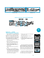
CHANNEL ACCESS jacks For example, a
mono plug inserted only to the first click does
not interrupt the master (main outputs,
headphone output, ALT-3/4 outputs). Plugged
all the way in, it becomes a direct out and
interrupts. This may seem weird at first, but
it’s the way. See page 16 for a picture
describing the plug and inserts.
The CR-1604 is fused for your (and its own) protection. If you suspect a blown fuse, disconnect the 28 AUX RETURNS TO MASTER
power cord, pull the fuse drawer just below the AC
This is where you connect the output of your
receptacle and replace the fuse with a 1-amp SLO
effects devices or, in some cases, return the signal
BLO fuse (or 1/2-amp SLO BLO fuse if the unit is a of a multitrack tape machine/mixdown deck.
230V model). 230V models have a bright red
Many mixers simply have a passive input cir230V sticker both on the shipping box and on
cuit for AUX returns. We have active input gain
the mixer itself. If two fuses blow in a row, somecircuitry which allows use of a wider range of exthing is very wrong. Call our toll-free number and
ternal devices. The circuits will handle stereo or
find out what to do.
mono unbalanced signals at instrument level or
–10dBV to +4dBu.
27 CHANNEL ACCESS, TIP=OUT, RING=IN
These eight inputs can be used for a variThis is where you connect series processors
ety of effects. (For more detailed information
such as compressors, equalizer, de-essers, or filters. on functions and their relationships to practiSince most people don’t have more than a few of
cal application in the production of your
these gadgets, we’ve included connections for just
music, see the Applications Guide in our In
the first eight channels. If you want to use this kind Your Face magazine.
of processing on Channels 9–16, simply plug into
29 BUS INSERT
and out of the device before you plug into the
CR-1604 channels. Connecting a processor here
These are the send and receive jacks for
will affect only the associated channel.
inserting an effect such as final compression,
limiting or EQ into the Main Left/Right Buses.
• Tip=output (send to external device),
Inserting a processor here will affect your
Ring=input (return from external device)
entire mix. See page 16 for a picture describ• The insert points are after the mic preamps,
ing the plug and inserts.
channel faders and equalizers (Post-Fader/
The BUS INSERTS can also be used as an
Post-EQ). This can be modified with a little
output
with no interuption to signal.
technical knowledge found on pages 33–34.
NOTE: The BUS INSERTS are pre-main
• CHANNEL ACCESS outputs are low-impedfaders. If you are using them for output, make
ance (120-ohm) and are capable of driving all
sure the connecting device has some way to
processors (except Cuisinart food processors).
adjust incoming level.
• For best results the device should be capable
• Tip=output (send to external device),
of at least +18dB input/output (any profesRing=input (return from external device)
sional unit). Do not use “stomp box”-style
•
The BUS INSERT is before the Master fader
devices. They simply can’t keep up with the
controls and after the main L/R mix amps.
operating level needed to match CR-1604
• Inputs and outputs are unbalanced and
performance.
designed to work with pro devices with at least
• The CR-1604’s CHANNEL ACCESS jacks are of
18dB of input/output.
a special design that gives more flexibility than
•
The BUS INSERT can also be used as a tape
regular jacks. What kind of plug you use and
out if plugged in the first “click”. Master
how far you plug it in varies the function of
adjustments will not affect level.
13
INPUT
OUTPUT
POD
30 ALT 3/4 OUT
INPUT
OUTPUT
POD
This is where the outputs appear from the
channels that have been assigned via the
MUTE/ALT switch. The post-EQ/post-fader/
post-panpot/pre-aux send signals from all of
the muted channels appear at these outputs.
Output is low impedance unbalanced and is
designed to drive any input from low to high
impedance. Maximum output level is +22dBu
with a nominal operating level of +4dBu.
NOTE: Engaging a channel’s MUTE/ALT
switch will deactivate its AUX sends. See the
next section for several nifty ALT-3/4 OUT
applications.
31 AUX OUTPUTS
These are low impedance unbalanced outputs for the signals sent from AUX sends 1
through 6 (post-fader/post-EQ). Output is low impedance and is designed to drive ANY input from
low to high impedance. Maximum output level is
+22dBu with a nominal operating level of +4dBu.
32 MONITOR OUT
33 BAL/UNBAL MAIN OUT – STEREO
These outputs are electronically balanced
(since they have both polarities available and are
capable of driving +4dBu lines with 28dB of headroom). They’re also low impedance.
• For most music recording and PA applications, unbalanced outputs are perfectly
acceptable. Use standard cables. For
cables runs over 50 feet, you may need a
balanced line to reject noise.
• Balanced output is 6dB hotter than the
unbalanced outputs.
• To use these outputs in balanced applications, connect a stereo phone plug as follows:
o!
Tip
= – (cold)
a typ
Ring = + (hot)
is
Sleeve = Ground This
Why is the tip cold and the ring hot?! Well
if you must know there are quite a few manufacturers that use this polarity configuration.
No, you cannot go inside the CR-1604 and
merely flip the wires around; doing so would
short out your meters and void your warranty.
If you absolutely must change the polarity try
internally modifying a TRS adaptor or use an
external phase reverser.
NOT
This is a low impedance unbalanced output
for the signals sent from the MON SEND (AUX1
pre fader/pre EQ). The output is designed to
drive ANY input from low to high impedance.
Maximum output level is +22dBu with a nominal 34 MONO MAIN OUT
operating level of +4dBu.
Same characteristics as the stereo MAIN
OUTs except that the signal combines Right
and Left Main Channels and the polarity is
reversed (tip = hot, ring = cold).
ONE FINAL NOT-SO-OBVIOUS OUTPUT
You can create a 32 or 48-channel mixer with
the Mackie Designs MixerMixer combiner. It connects all the outputs of up to three mixers without
losing channels via “cascading.” You can hook up
two or three CR-1604s together, providing you
with more of everything you love about our mixer
as your budget and/or needs grow. The 1/LEFT
and 2/RIGHT faders on each mixer become submix faders. And we offer an optional 100mm
Remote Fader to control the combined Main L/R
outputs. Not satisfied with this stroke of flexibility,
we’ve put together an ultra-affordable CordPack
that includes all the cables necessary to interconnect three CR-1604s. This way, you won’t go broke
buying 36 mono and three stereo cables piecemeal, which could add up to almost as much as
the MixerMixer itself.
14
The CR-1604’s stereo
PHONE jack. As you’ll see
from the Applications
Guide, we recommend connecting your monitor power
amp to this output in several cases.
Its output is HOT. First turn the PHONES
fader all the way off. Then rotate the power
amp’s level controls to 12 o’clock. Now bring up
the PHONES fader gently.
If in the past you’ve had to put up with conventional, grungy-sounding headphone amps, you
may initially be reluctant to “trust” the CR-1604’s
headphone output. Not to worry. The sound quality is exactly the same as the main outputs and
will not degrade your audio in any way.
A CLOSER LOOK
NEED MORE OF A GOOD THING?
Part 4 — CONNECTION TIPS
It’s now time to begin hooking up all the cool
stuff you want to mix together. At this point, you
rack mounters may want to rotate the CR-1604’s
input/output pod to its jacks-to-back position. Pod
rotation instructions start on page 20. If you want
everything in yo’ face, i.e. jacks on the same plane
as the controls, get our RotoPod bracket (see
details on page 20).
Instead of being included in this manual we
have provided an incredibly detailed Applications Guide with much more detailed (and
colorful) drawings than could be managed in a
2-color, letter-size manual. NOTE: If you somehow lost the Applications Guide in the
frenzied heat of unpacking your CR-1604,
your Mackie dealer should have some extras
stashed someplace. Or call 1-800-898-3211
and we’ll send you a replacement, pronto.
EFFECTS AND PROCESSORS
Most recording and PA setups use external
signal processors to enhance the sound: reverb,
delay, digital delay, equalizers and compressors
are the most common, but perhaps you have a
harmonizer or enhancer as well. All of these
devices can be grouped into two categories —
effects and processors, depending on what they
do and how they’re used.
EFFECTS (parallel processing)
These generate additional sounds that you
add to the mix, usually by making two simultaneous mixes: one is of the unmodified dry signal
that goes directly to the main outputs via the input channels; the other is an auxiliary mix that
is sent to the effects device. The output of the
effect is then mixed with the main output, usually through an AUX return. The most common
effects are reverb and digital delay.
PROCESSORS (serial processing*)
These devices modify the signal and completely replace it with the processed version.
Usually they are connected to only one microphone, instrument, or track at a time —
through a Channel Access or Stereo Bus insert or before/after the mixer. Processors
include compressors, limiters, filters or external equalizers.
ODD DUCKS
Some newer, digital “Swiss Army Audio Knives”
can be switched for compression, limiting and
whatever else struck the whim of the product designer. Check their manuals for details. You’ll
probably want to connect them based on how
you’re using them in your mix.
CONNECTING AN EFFECT WITH STEREO
OUTPUTS
Use two separate cables and plug into a LEFT/
RIGHT pair of an AUX return. The corresponding
stereo AUX RETURN Level knob will control both
sides of the effect equally.
CONNECTING A MONO OUTPUT EFFECT
If you want a signal to return to just the right
side, plug the effect output into just the RIGHT
AUX RETURN.
SEPARATE MONO EFFECTS IN L & R
If you plug different mono effects into an AUX
RETURN’s left and right jacks and press the
corresponding MONO button, you get up to eight
mono returns.
CHANNEL INSERTS
To connect a processor using the CR-1604’s
CHANNEL ACCESS jacks, use tip-ring-sleeve
plugs wired as shown. The “tip” plug goes to the
processor INPUT; the “ring” plug goes to the
processor’s OUTPUT. If you’re using these jacks
as channel inserts, adjust the TRIM controls after
you plug the processor in.
CHANNEL INSERTS AS DIRECT CHANNEL OUTS
You can also use the CHANNEL ACCESS jacks
as direct outputs from the channels (post-fader/
post EQ) to feed tape decks, DAT machines or
other mixers. (See drawing on following page.)
* — as compared to CEREAL processing, wherein
wheat, rice, oats, etc. are turned into strange, aliencolored breakfasts foods named after kiddie shows.
15
HOOK
UP
MONO PLUG
Channel Insert jack
Direct out with no signal interruption to master.
Insert only to first “click”
MONO PLUG
Channel Insert jack
Direct out with signal interruption to master.
Insert all the way in to the second “click”
HOOK
UP
STEREO
PLUG
Channel Insert jack
For use as an effects loop.
(TIP = SEND to effect, RING = RETURN from effects)
tip
SEND to processor
ring
sleeve
(TRS plug)
this plug connects to one of the
CR-1604’s Channel Insert jacks.
“tip”
“ring”
RETURN from processor
• Direct out with no signal interruption to
mains. Push a MONO plug into a CHANNEL
ACCESS jack until you feel it click once. In
this configuration the channel access is acting
as an independent direct out with no signal
interruption to the master.
• Direct out with signal interruption to master.
Push the plug all the way into the CHANNEL
ACCESS jack. The signal will now be interrupted from the master and be available at the
direct out only. Use this mode when connecting to the inputs of multi-track recorders.
• Effects Loop. A stereo plug wired as shown
in the drawing above turns the CHANNEL
ACCESS into a loop that will send and receive
to and from an external device using the same
channel access jack. Use this mode when
connecting to the inputs of multi-track
recorders.
CREATING SUB-MIXES
USING THE ALT 3/4 OUT
Surprise! The CR-1604 really has FOUR buses,
not just two! The following are working examples
of how to effectively use the flexibility of the
ALT 3/4 OUTPUT buses. In the first example, let’s
imagine that you want to create a separate drum
sub-mix. This setup is used to control the level of
all of the various channels that make up the drum
16
kit via two “sub master faders” (actually input
channels 15 & 16 of the mixer). For purposes of
this example, let’s assume that you have already
hooked up your drum mics or machine inputs to
Channels 1 through 5.
EXAMPLE 1
1. Now press the MUTE ALT 3/4 buttons on these
five input channels (They are no longer part of
your main mix but are now destined for the
sub-mix which in turn goes to the main mix.)
2. Next connect the rear panel ALT 3/4 outputs
back into two other channels of the CR-1604,
for example, Channels 15 and 16. These two
channels become your sub-mix level controls.
3. Pan Channel 15 HARD LEFT and Channel 16
HARD RIGHT, respectively, so that the
panning of Channels 1–5 will be reflected in
your stereo sub-mix. DO NOT engage the
mute/alt on these channels.
4. Adjust individual levels of the five drum
channels that are part of the sub-mix by using
their channel faders (1, 2, 3, 4, and 5).
5. Adjust the pan position of each drum channel
with that channel’s PAN pot.
6. Control the overall level of this drum sub-mix
within the main mix via Channel Faders
15 and 16.
7. Add effects and EQ to the submix channels
if desired.
EXAMPLE 2
You can also create sub-mixes without tying up
additional CR-1604 channels.
1. As before, press the MUTE ALT 3/4 buttons on
the five drum Channels (1–5). These channels
are no longer part of your main mix.
2. Connect the CR-1604’s ALT 3/4 Outputs to the
LEFT and RIGHT jacks of an AUX return,. In
our diagram we’ve used AUX 1, LEFT. Stereo
AUX RETURN 1 now controls the master drum
sub-mix level.
In either of these two setups, you can
instantly solo your sub-mix into your headphones (or monitor speakers if they are
connected to the headphone output) by
pressing the CR-1604’s ALT/PREVIEW button or soloing the submaster channels.
SUBMIX HOOKUP EXAMPLE 1
SUB-MIX
0
Pan Ch. 16
hard LEFT
L
CHANNELS TO BE SUB-MIXED
0
R
L
PAN
R
L
PAN
SOLO
SOLO
MUTE
MUTE
ALT 3/4
OL
16
+20
16
0
R
MUTE
these
channels
OL
15
14
13
L
MUTE
MUTE
ALT 3/4
R
PAN
SOLO
MUTE
ALT 3/4
ALT 3/4
OL
OL
OL
+ 20
+20
+20
+20
+20
5
4
3
2
U
HOOK
UP
1
U
U
U
00
1
BALANCED OR UNBALANCED LINE INPUTS
LOW Z BALANCED MICROPHONE INPUTS
00
5
L
LEFT
R
PAN
SOLO
OL
AUX RETURNS TO M
00
LEFT
3
2
L
0
OL
U
BUSS INSERT
ALT 3-4 OUT
R
PAN
ALT 3/4
UNBALANCED LINE INPUTS
1
L
0
SOLO
MUTE
ALT 3/4
U
00
R
PAN
MUTE
6
0
SOLO
+20
U
AUX / MONITOR OUTPUTS
L
PAN
SOLO
ALT 3/4
15
0
Pan Ch. 16
hard RIGHT
00
4
00
3
2
00
MIC INPUT
ADDS 8dB
ADDITIONAL
GAIN
1
R
4
5
RIGHT
6
RIGHT
ALT 3-4 OUT
Microphones are shown but
these could also be 1/4" line
inputs from drum machines .
SUBMIX HOOKUP EXAMPLE 2
SUB-MIX
CHANNELS TO BE SUB-MIXED
STEREO AUX RETURNS
sub-mix
level
set here
U
1
1
00
0
+15
1
L
U
L
MUTE
these
channels
2
2
+15
L
U
3
R
+15
L
U
R
L
0
BALANCE
R
L
PAN
MUTE
ALT 3/4
R
L
PAN
SOLO
MUTE
ALT 3/4
R
PAN
SOLO
MUTE
ALT 3/4
ALT 3/4
OL
OL
OL
OL
OL
+ 20
+20
+20
+20
+20
U
U
U
U
U
15
14
13
6
5
4
00
UNBALANCED LINE INPUTS
AUX / MONITOR OUTPUTS
2
L
R
16
LEVEL
1
0
SOLO
MUTE
ALT 3/4
Press AUX
SOLO to
solo
sub-mix
AUX
SOLO
4
+15
R
PAN
SOLO
MUTE
MONO
C
4
00
0
4
3
00
L
SOLO
C
3
R
PAN
R
C
2
00
0
C
BUSS INSERT
ALT 3-4 OUT
AUX RETURN
L
3
LEFT
3
00
2
00
1
00
00
BALANCED OR UNBALANCED LINE INPUTS
LOW Z BALANCED MICROPHONE INPUTS
5
4
3
2
1
MIC INPUT
ADDS 8dB
ADDITIONAL
GAIN
1
LEFT
R
4
5
6
RIGHT
ALT 3-4 OUT
RIGHT
AUX RETURNS
TO MASTER
MIC or line inputs for submix
17
ASSORTED NUGGETS OF MONITORING WISDOM
A CLOSER LOOK
CAN YOU TRUST YOUR EARS?
Even if you have perfect
hearing, your ears will not always give you a true idea of what
is being heard.
Expecially if you like to really
crank your monitors while mixing. As the session
progresses, your ears will have a tendency to become accustomed and eventually numb to volume
and EQ levels. We call this phenomenon ear fatigue.
The longer your session, the more ear fatigue you’ll
encounter.
EXAMPLE : Have you ever spent an entire night
working on a song trying to get the EQ and volume
just right, only to find that when you listen to your
results the next day you are horrified by the shrillness and lack of separation ?
This is a symptom of ear fatigue. By the end of
the session, your ears had become accustomed to
the EQ level...so you cranked in some more mid and
highs. You also cranked the monitor amp level up
every once in a while, so by the wee hours, things
sounded distinct to you (after all, you were listening
at a VERY high volume which tends to help
definition...until you turn the level back down and
discover mush at normal volume).
To avoid this, give your ears a break every hour
or so they can recuperate. Also, it is a good idea to
resist the temptation to start out mixing with a real
high output level because this will speed up the
process of ear fatigue.
Your mixer can become a victim of this vicious
circle as well. Avoid inching up your levels in order
to get better separation. Watch EQ levels, too. You
may think you can get better results by adding a lot
of EQ to a guitar or keyboard part to open up the
mix. But eventually your CR-1604 can become overwhelmed by heavy-handed EQ and excessive output
levels, creating what we call mixer mush.
Like we said, take a rest every once in a while. If
things start getting out of hand in regards to the
overall clarity of your mix, stop for awhile, go grab a
soda or order in a pizza or both. What the heck. Big
studios do it everyday !!
You’ll find these rest times are a far better use
of time than if you just bear down and twist some
more knobs.
HOOK
UP
CAN YOU TRUST YOUR MONITORS?
Another common problem that many new engineers experience is the Big Studio Surprise . It
happens when they take their tape to a larger studio
with better monitors.
“Gee, the bass didn’t sound that boomy at my studio”
“Where’s the guitar solo?””
“The cymbals sound like garbage can lids !!”
CARE AND FEEDING OF YOUR CR-1604
• If you’re going to use the CR-1604 in a
horizontal position (the mixer, not YOU!),
cover it when not in use to prevent dust for
settling in the faders.
• To clean grunge out of the channel faders,
use “canned air” which is available at photo
shops. It comes in compact spray cans.
18
If this has ever happened to you, don’t feel bad.
You can’t appreciate a color movie if all you have is
a black and white TV. And just like having a good video
monitor, the key to successful music production is an
accurate idea of what your mix really sounds like.
In order to do this properly, several things must
be present. The first and foremost is a quality set of
control room monitors and a clean power amp with
plenty of dynamic headroom.
These two components are indispensable if you
are to achieve the album quality product that many
of our professional users achieve with their CR-1604’s
(one recent album mixed on the CR-1604 was submitted for a Grammy nomination... in the classical
category where they’re sticklers for sound quality).
If your current monitors are an old set of POLY
POOPALA liquid cooled monoliths that you bought
off your roommate for a hundred bucks, and your
amp is the stereo receiver you bought with your paper route money 15 years ago, you can be assured
that whatever you create with your CR-1604 will
most likely not sound right if played on any other
system. Save cheap hi-fi speakers and wimpy 30watt amps for your next garage sale.
Instead, spend the money on serious monitor
speakers and a beefy amplifier.
Actually we recommend two or three sets of
speakers: First, a good quality pair of near field
monitors. This is a mandatory investment if you’re
serious. They’re critical to accurate perception of
what you’re creating, since as you move close to
true near field monitors, the room’s acoustics no
longer become as large a factor. You can then hear
exactly what’s happening. Next, get a pair of cheap
mini-speakers. These simulate boom boxes, car radios, etc. Finally, if you’re not out of room and
money yet, get a pair of larger speakers with 10 or
12-inch woofers. They can be pro-style studio monitors or just quality stereo speakers with good bass
response. This pair gives you the other end of the
consumer spectrum and helps with adjust bass response to fit your potential audience’s hi-fi systems.
“DO I HAVE TO?” Like we said at the beginning
of this manual, it’s your music. Good monitors and
power amps don’t have to cost a fortune.
DON’T DEVELOP TUNNEL HEARING
Even if you have ultra-accurate monitor speakers, remember, not everyone else does. Experiment
with different systems to really hear what your music
sounds like. Take your rough mixes to your friends
house and play it on his stereo or pop a cassette of
your mix into your car stereo. This will give you a
wider feel for what your studio monitor system is really telling you. This is exactly why there are always
at least two sets of monitors in big recording studios.
Just shove the nozzle into the fader slot
and blast away. Do not use any solvents.
• To clean fingerprints, diet Pepsi and
peanut butter off the surface of the mixer,
spray Windex or other ammonia-based
window cleaner on a rag and rub at will. Do
not spray cleaner directly on the mixer lest
it get into the faders.
SENSITIVITY/LEVEL ADJUSTMENT —
The long version
QU
ICK
VERY IMPORTANT
As we noted at the beginning of this manual
achieving the CR-1604’s imST
AR
pressive noise and
T
headroom specs, requires
adjusting channel sensitivity to your particular setup.
Can you run the mixer
without this adjustment?
Sure. Chances are that you’ll get pretty good
sound. But take a moment to adjust things
properly and you’ll get excellent sound. After
all, its your music.
SENSITIVITY ADJUSTMENT STEPS
(repeat for each channel being used)
1. If you have some idea of how the channel is going to be EQed, set it now. If not,
it’s no biggie. EQ will affect levels
somewhat, but not enough to totally
knock things out of whack.
2. Rotate the channel’s PAN control hard
RIGHT or hard LEFT. Leaving PAN in the
center position will reduce level indications by 6dB.
3. Set the channel’s Fader to the detent
Unity position.
4. Turn the channel’s SENSITIVITY control
fully counter clockwise (+4 UNITY).
That’s the small knob just above the
channel line input on the CR-1604’s
input/output pod.
5. Press the SOLO TO MAIN button on the
CR-1604’s output section. (Optional.)
6. Press the SOLO button on the channel
you’re about to adjust. The level will appear
on the CR-1604’s LED output meters.
7. Make some appropriate music through that
channel. Don’t just play one sustained note,
but rather jam away as you would normally.
If you’re adjusting the level for a channel
connected to a microphone, have the
performer(s) sing/blow/strike/play at the
level they’re going to record or perform at.
8. If you’ve set PAN hard left, view the level
on the left LED row. If panned hard right,
the level will appear on the right LED row.
9. While the sound source is activated, turn
the channel’s SENSITIVITY control
clockwise until the level on the CR-1604
meter reads about OdB.
10. Un-SOLO the channel and return the
PAN control to center or however you’re
going to set it during use.
11. Repeat this procedure for each channel,
using the appropriate kind of source
which will be used with that particular
channel.
• When in actual use, avoid running the level
into the CLIP range of the meter, as your
sound quality may suffer. It’s OK for the
+2,+4, and +8 indicators to light up occasionally but only during peaks in the signal
such as drum hits, or when the bass player
accidently gooses one of the backup singers
with the neck of his Steinberger, etc.
• Note that you must add 10dB to the
markings on the SENSITIVITY control
when using the and mic inputs.
• Once you have performed this simple
calibration, there should seldom be a
need to readjust your input sensitivity
unless a different kind of input is being
used with that channel.
• Adjusting the channel this way (with 0dB
as maximum) is a conservative approach
that assumes things could get louder
later on. The sensitivity can be set just a
tad higher, if you watch levels carefully
during use.
19
LEVEL
SETTING
STEPS
CHANGING THE POD TO
RACK MOUNT POSITION
CHANGING
THE POD
It only takes about five minutes and a
Phillips-head screwdriver to change the CR1604’s input/output pod from tabletop to
jacks-to-back position.
1. Remove all cords and cables from the
mixer, including a lamp if you’ve plugged
one in.
2. Place the mixer gently face down on a
clean, soft surface such as a blanket or
very large dog.
3. Remove the four #6 screws securing the
small slotted black plate on the bottom of
the main part of the mixer. Keep track of
which screws go where.
4. Remove the two #8 screws on each side of
the mixer which secure the pod. Gently
pull the pod away from the main chassis.
5. Lift the pod over the main part of the
mixer. Replace the slotted plate but install
it turned around 180˚ with the ribbon
cables in the slot.
6. Lower the pod back onto the slots.
7. Reinstall two #8 screws on each side to
secure the pod. DO NOT press hard while
inserting these screws.
8. Install the rack “ears” on the sides of the
mixer. DO NOT press hard while inserting
these screws.
The BNC lamp socket is no longer accessible in this position.
Remove back plate
Remove screws here on each side.
Replace back plate
after rotating 180˚.
Thread ribbon cable
through slot
Add screws here.
Then add rack rails
JACKS TO TOP?
You can also rotate the pod so that the inputs
and outputs are on the same plane as the main
CR-1604 controls. This requires our handy dandy
RotoPod bracket. It comes with its own set of
extended rack rails so that the mixer can be rack
mounted in this configuration. Consult your dealer
for exciting details.
20
WARRANTY SERVICE
The complete fine print of our Warranty is
attached to the warranty card that came with
your mixer. If you can’t find it, call us and
we’ll send you another one.
Also make sure to save your sales receipt.
It’s useful in establishing when you bought
the mixer and for insurance purposes if someone happens to borrow your entire studio
while you were on vacation in Mazatlan.
TROUBLESHOOTING
We haven’t included a gigantic troubleshooting chart with circles and arrows and
captions on the back because our Service Department and support persons are here to
handle that sort of thing. Still, there are some
simple tests you can make before you call to
determine if your CR-1604 is really the culprit. This saves time all around and prevents
you from feeling sheepish when it turns out
that it’s really your Blort-Tronics Sonic
Defrabulator that’s creating the problem,
and not our mixer.
Bad channel
Is the channel un-muted? Fader up?
(Honest, this happens.)
Unplug all Bus Insert and Channel Access
hookups.
Switch output cords. For example, if the
left output is dead, switch the left and right
output cords at the mixer. If the problem
moves to the right, it’s not the mixer.
Bad output
Is the output un-muted? Faders up?
Unplug all Bus Insert and Channel Access
hookups.
Switch output cords. For example, if the
left output is dead, switch the left and right
output cords at the mixer. If the problem
moves to the right, it’s not the mixer.
Noise
Turn all faders and AUX returns down. If
the noise goes away, bring levels back up one
at a time, checking for noise at each step.
Unplug everything except the output
where the noise was detected. If the noise
goes away, plug everything back in one at a
time, checking for noise at each connection.
Power
Check the CR-1604 fuse (see page 12).
REPAIR
Service for the CR-1604 is only available
from the Mackie Designs factory in scenic
Woodinville, Washington.
If there is a problem with your mixer:
1. Review the troubleshooting suggestions at
left.
2. Call us to confirm that the CR-1604 needs
repair and to get an RA number. You must
have a Return Authorization Number
(RA). Call us at 1-800-258-6883, 8 AM to 5
PM Pacific time, Monday through Friday to
get this number. Products shipped to us
without an RA number will be refused.
3. If you have rotated the pod, return it to its
original position (jacks pointing towards
the back). If you’ve added a RotoPod,
remove it and return the pod to original
position. If you’ve added an XLR10,
remove it.
4. Set aside the rack ears, manual and cord.
We won’t need these to repair the mixer
(unless you have interharmonic underslewing bipolar crosstalk in your rack ears,
a rare but particularly nasty problem...)
5. Pack the mixer in its original shipping
carton with the foam end caps in place.
This is VERY IMPORTANT. If you do not
have the carton, just ask for one when you
get your RA number and we’ll ship it to you
promptly.
CR-1604
with
pod
to
top
CR-1604
with
pod
to
top
Be sure to return the CR-1604 in its original
“desktop” mode and remove the rack ears!
21
TECH
STUFF
6. Include a note stating:
a. Your return address and phone number
b. A brief description of the CR-1604’s
problem
7. Write the RA number in BIG PRINT on the
outside of the shipping carton.
8. Send us the mixer. We recommend U.P.S.
Remember to insure the mixer. U.P.S. will
help you with this. Ship your CR-1604 to:
Mackie Designs, attn: Service
16220 Wood-Red Rd. NE
Woodinville, WA 98072, U.S.A.
9. We’ll try to fix the mixer within three business days. We send everything back prepaid
U.P.S. BLUE (Second Day Air) unless you have
sent your CR-1604 to us for warranty service by
NEXT DAY or SECOND DAY AIR. In that case,
we figure you need it fixed ASAP, so we put it at
the head of the line and ship the unit back
U.P.S. RED (Next Day Air). This policy doesn’t
not apply to non-warranty service.
TECH
STUFF
22
SPECIFICATIONS
Frequency Response:
20Hz–40kHz ±1dB
Distortion:
less than 0.025%, 20Hz–20kHz
Noise:
Mic E.I.N.
–129.0dBm, 150Ω source
–133.7dBV input shorted
Main output noise: –86dBu
Working S/N ratio: 90dBu
(ref: +4dBu)
Max. Output:
+28dBu main output balanced
+22dBu all other outputs unbalanced
Dynamic Range:
108dB
Max Gain
Mic: 48dB
Lines 1–6: 40dB
Lines 7–16: 25dB
Mic in to balanced line out: 84dB
Mic in to unbalanced line out: 78dB
Channel faders : 20dB
AUX return: 20dB
L/R master: 10dB
Channel-to-Channel Crosstalk:
–85dB
Headphone Impedance/Output:
20–2000 ohms/200mW.
Equalization:
Hi: Shelving, ±15dB @12kHz
Mid: Peaking, ±12dB @2.5kHz (3.3 octave)
Lo: Shelving, ±15dB @80Hz
Phantom:
160mA, 10mA/CH.
Power Supply:
35 Watts
Weight:
18 lbs.
CR-1604 DIMENSIONS
(including XLR10 & MixerMixer add-ons, RotoPod bracket)
0.7"
16.1"
4.5"
16.1"
3.8"
6.6"
5.9"
pod
to top,
FLUSH
rack mount,
with
XLR-10
CR-1604
with
pod
to
top
9.25"
10 rack spaces
19.0"
pod
to top,
RECESS
rack mount,
with
XLR-10
5.9"
6.6"
5.5"
RotoPod
bracket,
XLR10,
extended
rails,
FLUSH
rack
mount
18.2"
CR-1604
with
RotoPod
backet &
extended
rails
15.8"
Note: RotoPod rack rail places mixer flush with
1.5" bottom rack space, allows gap at top for cables.1.6"
18.2"
15.8"
12.7"
11 rack spaces
4.8"
RotoPod
bracket,
extended
rails,
RECESS
rack
mount
2.3"
3.05"
12.0"
9.25"
CR-1604
with
pod
to
back
17.34"
including screw heads
pod
to back
FLUSH
rack
mount
with
XLR10
2.3"
0.5"
0.5"
7.1"
pod
to
back,
RECESS
rack
mount
3.05"
Remote Fader
15.7"
17.1"
2.3"
MixerMixer
7.5"
3.0"
1.5"
16.7"
4.0"
XLR-10
1.4"
1.65"
2.6"
2.1"
12.0"
7 rack spaces
6.4"
16.2"
Note: Dimensional drawings are shown with optional XLR10 and RotoPod.
23
TECH
STUFF
CR-1604 BLOCK DIAGRAM
CHANNELS 1-6
PHANTOM
POWER
2
MIC GAIN
+10dB to +50dB
3
4
LINE GAIN –
UNITY TO +40dB
MIC
INPUT
3
1
1
5
RING IN
SOLO SW
LEFT
TIP OUT
SOLO
CHANNEL
FADER
OFF TO
+20dB
GAIN
6
POINT
A
2 (HOT)
2
CHANNEL ACCESS
FIRST CLICK=
DIRECT OUT
(NO SIGNAL
INTERUPTION)
1
GAIN TRIM:
3-BAND
EQUALIZER
80, 2.5K,12K
3
PEAK
LED
ALT 3-4 LEFT
CHAN
MUTE
(ALT
3-4)
PAN
DISCRETE
MIC AMP
RIGHT
LEFT MAIN
RIGHT MAIN
2-WAY
SENSE
ALT 3-4 RIGHT
PRE/MONITOR SIGNAL
LINE
INPUT
10dB PAD
CHANNELS 7-16
"You're either on
the bus or off the
bus."
Ken Kesey
7
AUX 1
AUX AMP
8
9
FROM
XLR10 EXPANDER
1
10
11
TRIM
UNITY TO +25dB
MON
12
EXPANDER
MIX AMP
13
OFF TO
20dB
GAIN
14
15
LINE
INPUT
POINT
A
1
MONITOR
AUX 1
2
16
3
AUX 2
AUX
SENDS
NOTE: LINE INPUTS ONLY ON CHANELS 7-16,
(FOR MIC INPUTS USE XLR-10 EXPANDER MODULE).
5-6 SHIFT
5
4
1
AUX RETURNS 1-4
2
GAIN
6
AUX 3-5
3
OFF TO
+20dB GAIN
4
RETURN
LEFT
AUX 4-6
LEFT
BALANCE
SOLO
MONO
RIGHT
AUX 1
AUX 1 MONITOR
AUX 2
AUX 3
AUX 4
AUX 5
AUX 6
RETURN
RIGHT
max out +22
level up +20
+14 max in
0
level up +15
0
0
-8 trim dn
to point (B)
MIC INPUT
0
AUX RETURN
CH. LEVEL
MIX
-48 trim up
0
fader up +10
(A)
0
LINE INPUT
CH 1–6
INSERT
-40 trim up
0 (B)
EQ
FADER
PAN
CHANNEL
-25 trim up
24
0
-6
0
(C)
MIX
INSERT
FADER
MASTER
+22 max in
0
-6
0
to meters
METER FEED (+0dBu @ O/P = 0 @ METERS)
max out +22
L/R unbal
0
pan center -6
gain dn -15
LINE INPUT
CH 7–16
OUTPUT
L/R bal max out +28
fader up +20
gain up +15
0 trim dn
0
AUX SEND
+22 max in
0 trim dn
0
from point (A)
OUTPUT
to Albuquerque
TIP OUT
LEFT BUS
INSERT
FIRST CLICK=
DIRECT OUTPUT
(NO SIGNAL
INTERRUPTION)
RING IN
L R
+
+28dBu MAX BALANCED
+22dBu MAX UNBALANCED
L
TIP OUT
RIGHT BUS
INSERT
FIRST CLICK=
DIRECT OUTPUT
(NO SIGNAL
INTERRUPTION)
MAIN
MIX AMPS
RING IN
MASTER
OUTPUT
MUTE
SWITCH
MASTER
LEFT & RIGHT
OFF TO
+10dB GAIN
+
ELECTRONIC
SOLO
SWITCHING
ALT 3-4
LEFT OUT
BALANCED
MAIN RIGHT
OUTPUT
-
R
L
BALANCED
MAIN LEFT
OUTPUT
-
+28dBu MAX BALANCED
+22dBu MAX UNBALANCED
(ONLY WITH
SOLO TO
MAIN
SWITCH
ENGAGED)
ALT
PREVIEW
-
ALT 3-4
MIX AMPS
BALANCED
MAIN MONO
OUTPUT
+
+28dBu MAX BALANCED
+22dBu MAX UNBALANCED
ALT 3-4
RIGHT OUT
R
L
SOLO
MIX AMPS
L
TIP
R
PHONES
AND
SOLO
LEVEL
RING
STEREO
HEADPHONES
OUTPUT
R
1
AUX 1
1
AUX 1
MONITOR
2
AUX 2
OUTPUT
3
AUX 3
OUTPUT
+22 CLIP
4
AUX 4
OUTPUT
+4
5
AUX 5
OUTPUT
6
AUX 6
OUTPUT
OUTPUT
METER
NOTES:
1. SWITCHES SHOWN IN
"NORMAL" POSITION.
MAIN LEFT
MAIN RIGHT
ALT 3-4 LEFT
ALT 3-4 RIGHT
SOLO LEFT
SOLO RIGHT
+8
+22dBu MAX
ALL AUX SENDS
+2
0
ELECTRONIC
SOLO
SWITCHING
-4
-8
TECH
STUFF
METER READS
INPUT CHANNEL
LEVEL WHEN
CHANNEL IS
SOLOED.
-12
-16
-20
CR-1604
BLOCK DIAGRAM
Rev.
©1995 Mackie Designs
25
10 COMMON QUESTIONS
1. How do I get the effects into my monitors?
2. How do I get effects out the ALT 3/4 Bus?
3. How do I set up a monitor or auxiliary send master?
4. What modifications can be done to the mixer?
5. How do I perform the modifications to my mixer?
6. Can I use the Bal./Unbal. Main Outputs and Mono
Output at the same time?
7. Can I split the Main Outputs with a Y-cord?
8. Can I use the XLR Mic Inputs for line inputs?
9. How do I record with effects?
10. Why are there really only 9 questions?
TECH
STUFF
(1) Q: How do I get the effects into my monitors?
A: Instead of connecting the output(s) of an
effect device to the AUX RETURN TO MASTER
jacks, it should be connected to the line input(s)
of unused channels. This would make the channel fader(s) the AUX RETURN to main output
control. This channel or channels should be set
up as if it were receiving any line input signal.
This means setting the proper input trim level
with the fader at unity and setting the pan control (stereo or mono). You now have the effect
going to your main outputs.
Now to get the effect to the monitors simply turn up your monitor send on that
channel (the one you have connected the output of the effect to). The AUX OUT is still
connected to the input of the effect the same
way and the individual channels are still sent
to the effect the same way. The only difference is how you are controlling the return
level of the effect.
Using this configuration you must remember one important point — NEVER turn up
the AUX SEND level of the particular effect
on the channel you are using as the AUX RETURN. This will give you a feedback loop. For
example, if you are using AUX SEND 2 for a
reverb send and you are using channels 15
and 16 as your stereo AUX RETURNS, you
would NEVER want to turn up AUX SEND 2
on channels 15 and 16.
It may seem that you are losing inputs by
configuring the aux returns this way but you
are not. Your unused AUX RETURNS TO
MASTER JACKS can now be used as inputs.
By engaging the MONO switch on the AUX
RETURNS you can have up to 8 mono inputs.
Also, by returning the output of the effect to a
channel you can now use the EQ to further
enhance the effect.
(2) Q: How do I get effects out of the ALT 3/4 Bus?
A: You will need to perform option #1, 2, or 3
in the modification sheets in order for an individual channel to be muted (sent to the ALT
3/4 Bus) and still be capable of sending channel information out of the auxiliary sends.
Instead of connecting the output(s) of an
effect device to the AUX RETURN TO MASTER
jacks, it should be connected to the line
input(s) of unused channels. This would make
the channel fader the auxiliary return master.
26
The channel should be set up as if it were
receiving any line input signal. This means setting the proper input trim level with the fader
at unity and setting the pan control (stereo or
mono). Next you would MUTE the channel
which would send the auxiliary returns out the
ALT 3/4 Bus.
(3) Q: How do I set up a monitor or
auxiliary send master?
A: There are two ways:
1) Insert a mono 1⁄4" cord into the auxiliary
(monitor) output jack and return the other
end of the cord to the line input of an unused
channel. Engage the MUTE button on the
channel which will send the signal out to the
ALT 3/4 bus. Pan the channel hard left or
right depending on which bus (3 or 4) you
want to come out of. Connect another mono
1⁄4" cord from the corresponding ALT bus 3 or
4 output to the input of the monitor amplifier.
or
2) Insert a mono 1⁄4" cord into the auxiliary
(monitor) output jack and return the other
end of the cord to the line inputs on either of
the channels 1–8. Connect another mono 1⁄4"
cord from the corresponding channel access
jack to the input of the effect device or monitor amplifier. Make sure to insert the plug all
the way into the access jack on the mixer so
the signal will not go to the main L/R outputs.
Either of these 2 ways will allow you to control the overall level of the auxiliary or monitor
sends by using the channel fader as your master. Treat it as if it were any signal but be
careful when you increase the individual channel send levels because this may eventually
clip the input stage on the master send channel. If this happens, simply turn down the trim
on the master send channel a little bit.
(4) Q: What modifications can be done to the
mixer?
(5) Q. How do I perform the modifications to my
mixer?
A: Boy, are we glad you asked! Due to
overwhelming demand we have included a
section especially for Propeller-Head-Types
on the next few pages called “MODIFICATIONS-O-RAMA”.
(6) Q: Can I use the Bal/Unbal Main Outputs and
Mono Output at the same time?
A: Yes! This will not degrade the signal in
any way. Remember the polarities on the main
and mono outputs when running balanced
lines (see page 14 of the Owner’s Manual).
This configuration can be very useful when
an extra monitor send or a mono recording is
needed. The mono output will be the
summed output of the L/R Main Output.
It is important to remember that the Mono
Output will be the same level as the Main
Output but can be controlled at the monitor
amplifier. It can also be controlled by connecting the Mono Output to the line input of
an unused channel and Muted to the ALT 3/4
Bus and then connected to the monitor amplifier — this can be a little tricky because
when the main output fader levels change so
do the monitor levels.
(7) Q: Can I split the signal at the Main
Outputs with Y-cords?
A: Yes! There is more than enough signal
strength available at the Main Outputs to drive
the high impedance inputs of two devices with
no quality loss of the original signal. For example, if you wanted to record the Main
Output to a cassette deck as well as a DAT, two
Y-cords could be used to send an identical signal to both devices. This type of configuration
could be very useful for many applications.
Auxiliaries:
Option #1: Pre EQ, Pre Fader, Pre Mute/ALT
Option #2: Post EQ, Pre Fader, Pre Mute/ALT
Option #3: Post EQ, Post Fader, Pre Mute/ALT
(STOCK: Post EQ, Post Fader, Post Mute/ALT)
Channel Access:
Option #4: Pre EQ, Pre Fader
Option #5: Post EQ, Pre Fader
(STOCK: Post EQ, Post Fader)
27
TECH
STUFF
(8) Q: Can I use the XLR Mic Inputs for
balanced line inputs?
A: No and Yes. IMPORTANT!!!!!! The way
the board is configured from the factory it is
not meant to accept a line level signal at the
Mic Inputs. Although the mic and line inputs
pass through the same preamp stage, the line
input has an internal 10dB pad. This 10dB
pad can be accomplished externally by connecting two resistors into the XLR cord being
plugged into the XLR jack.
The procedure for this is: solder one 4.7K
(4,700 ohm) resistor is series with pin 2 (typically +) and one 4.7K (4,700 ohm) resistor in
series with pin 3 (typically “–”). Solder the
ground connection as normal.
The most important thing to remember
about connecting line inputs to the XLR Mic
Inputs is NEVER NEVER TURN ON THE
PHANTOM POWER unless you put a 22µf 50V
electrolytic capacitor in series with each resistor on pins 2 and 3. The positive leg of the
capacitor should be at the mixer end.
(9) Q: How do I record with effects?
TECH
STUFF
A: There are three ways:
1) During tracking or overdubbing, use the
Main 1/2 outputs to feed your multitrack and
keep the effects returns connected to the Aux
Returns to Master jacks. This way the multitrack will get effects. Use the MUTE ALT 3/4
to feed the amp and speakers for monitoring
purposes by muting (ALT 3/4) the multitrack
returns. When it is time to mix simply connect the Main 1/2 Outputs to the amp for
monitoring the mix.
2) When using direct outputs from the
mixer to feed the multitrack inputs, the best
way to record with effects is to place the effect
device in between the mixer and the multitrack. You should use the “mix” potentiometer
on the effect device to determine how much
effects are wanted on the original signal. This
would have to be done on a per channel basis.
3) Recording with effects can also be done
using the ALT 3/4 outputs by muting the original
signal and muting effects returned to channels.
Connecting the ALT 3/4 outputs to the multitrack inputs gives you effects to tape. Mod #3
must be done first. (See question 2.)
28
(10) Q: Why are there really only 9 questions?
A: There are two reasons:
1) Due to an unforseen space-time rift, the
tenth answer slipped back in time before the
question ever happened and cancelled out its
own existence.
2) This is actually a trick question. The
tenth question negates itself simply by being
the tenth question. It’s kind of like saying,
“This statement is false.” The statement is
only true if it’s false. But if it’s false then it
would be true… oh, nevermind. If you’re not
a student of logic, just pretend like this question never really happened in the first place.
MODIFICATIONS-O-RAMA
CHANNEL ACCESS mods
The CR-1604 can be modified to move the
position of AUX Sends and Channel
STOCK CHANNEL
MOD 4
MOD 5
Inserts in the signal flow. Unless you
ACCESS JACK
PRE-EQ
POST-EQ
POST-EQ
have the right tools and have tweaked PRE-FADER
PRE-FADER
POST-FADER
PRE MUTE/ALT
PRE MUTE/ALT PRE MUTE/ALT
with circuitry before, leave these
MUTE
EQ
CH. FADER
ALT 3/4
TO
mods to a pro. Our Official Word on
ALT
3/4
modifications is: “Any internal
BUS
modification of the
1
MUTE
CR-1604 MUST be per- INPUT
formed by a competent
TO
MAIN
technician. Mackie Designs ac1/2
cepts no responsibility in the event of
BUS
EQ
improperly performed modifications
STOCK
or other damages and, in such
MOD 1
MOD 2
MOD 3
AUX SEND
PRE-EQ
POST-EQ
POST-EQ
POST-EQ
cases, may declare warranty privi- PRE-FADER
PRE-FADER
POST-FADER
POST-FADER
PRE
MUTE/ALT
PRE
MUTE/ALT
POST
MUTE/ALT
PRE
MUTE/ALT
leges void.” Be VERY careful!
Here are the most common CRAUX SEND mods
1604 modifications, six of which are detailed
on the following pages.
0
HI
+20
–15 +15
0
MID
U
PREAMP
ALT 3/4
–12 +12
0
LO
00
–15 +15
1. CONVERT AUX SENDS TO MONITOR
SENDS (Pre-EQ, Pre-Fader, Pre-Mute/ALT
Switch).
Can be done on any or all of channel strips
1 to 16. Each channel modification requires
cutting one or more circuit traces and adding
a small jumper wire. On each strip, you can
modify Sends 2, 3, 4 or any combination
thereof. Note: Converting AUX 3 will also convert AUX 5; converting AUX 4 will also convert
AUX 6. See the next page.
2. CONVERT AUX SENDS INTO MONITOR
SENDS WITH EQ (Post-EQ, Pre-Fader, PreMute/ALT Switch).
Can be done on any or all of channel strips
1 to 16. Each channel modification requires
cutting one or more circuit traces and adding
a small jumper wire. On each strip, you can
modify Sends 2, 3, 4 or any combination
thereof. Note: Converting AUX 3 will also convert AUX 5; converting AUX 4 will also convert
AUX 6. See pg. 31.
4. CONVERT CHANNEL ACCESS (INSERTS)
TO PRE-EQ / PRE-FADER.
Can be performed on any or all of the first
eight CR-1604 channel strips. Requires cutting
three circuit traces and adding both a small
jumper wire and a 22µf/16V electrolytic cap on
each channel strip. See pg. 33 of this section.
TECH
STUFF
5. CONVERT CHANNEL ACCESS (INSERTS)
TO POST-EQ / PRE-FADER.
Can be performed on any or all of the first
eight CR-1604 channel strips. Requires cutting three circuit traces and adding both a
small jumper wire and a 22µf/16V electrolytic
cap on each channel strip. See pg. 34 of this
section.
6. TIE SOLO TOGETHER ON TWO OR MORE
CR-1604s.
POD
b
b
a
MAIN CHASSIS
POD
See pg. 35 of this section.
MAIN CHASSIS
3. CONVERT AUX SENDS TO IGNORE
MUTE/ALT STATUS (Post-EQ, Post-Fader, PreMute/ALT Switch).
POD
Can be on any or all of channel strips 1–16.
Converts ALL AUX sends on each channel
strip. Requires cutting a circuit trace, and
adding both a small jumper wire and a
20,000Ω resistor. See pg.32 of this section.
29
Modification 3&4
Modification 1&2
PRE-EQ • PRE-FADER • PRE-ALT/MUTE MODIFICATION
AUX 4
AUX 3
AUX 2
Add jumpers (d)
cut traces (c)
TECH
STUFF
Modification 1 — AUX SEND
PRE-EQ • PRE-FADER • PRE-ALT/MUTE
POD
b
b
a
MAIN CHASSIS
POD
MAIN CHASSIS
POD
This modification converts AUX Sends into
pre-EQ/pre-fader/pre-ALT/mute Monitor
Sends. You can modify AUX 2, AUX 3 and/or
AUX 4 on any or all of the CR-1604’s 16 channels. Converting AUX 3 also converts AUX 5;
converting AUX 4 also converts AUX 6.
1. Remove all cords from the CR-1604 and
place it face down.
2. Remove ribbon cable plate cover (a).
Keep track of what screws go where!
3. Remove pod mounting bolts (b) and
separate pod from main chassis.
4. Remove bottom and side screws from
main chassis.
5. Remove main chassis cover and set it
aside.
6. Cut traces to selected AUX Sends (c).
7. Add jumper wires [shown as grey lines
(d) in illustration] for those AUX Sends
with cut traces. Don’t smash the wires
down tight onto the circuit board. Let
them “arch” above if possible.
30
8. Replace main chassis cover and reattach
top and side screws.
9. Reconnect main chassis and pod;
replace side screws.
10. Gently nudge any slack ribbon cable into
the main chassis and replace ribbon
cable cover.
Any internal modification of the CR-1604
must be performed by a competent electronic
technician. Mackie Designs accepts no responsibility in the event of improperly performed
modifications or other damages and, in such
cases, may declare warranty privileges void.
* Note: Traces on different channels may
vary slightly from the drawing. (Engineering
sez channel strips are like snowflakes).
Modification 3&4
Modification 1&2
POST-EQ • PRE-FADER • PRE-ALT/MUTE MODIFICATION
AUX 4
Add jumpers (d)
AUX 3
cut traces (c)
AUX 2
Add jumpers (d)
TECH
STUFF
Modification 2 — AUX SEND
POST-EQ • PRE-FADER • PRE-ALT/MUTE
This modification converts AUX Sends into
post-EQ / pre-fader / pre-ALT/mute Monitor
Sends. You can modify AUX 2, AUX 3 and/or
AUX 4 on any or all of the CR-1604’s 16 channels. Converting AUX 3 also converts AUX 5;
converting AUX 4 also converts AUX 6.
1. Remove all cords from the CR-1604 and
place it face down.
2. Remove ribbon cable plate cover (a).
Keep track of what screws go where!
3. Remove pod mounting bolts (b) and
separate pod from main chassis.
4. Remove bottom and side screws from
main chassis.
5. Remove main chassis cover and set it
aside.
6. Cut traces to selected AUX Sends (c).
7. Add jumper wires [shown as grey lines
(d) in illustration] for those AUX Sends
with cut traces. Don’t smash the wires
down tight onto the circuit board. Let
them “arch” above if possible.
8. Replace main chassis cover and reattach
top and side screws.
9. Reconnect main chassis and pod;
replace side screws.
10. Gently nudge any slack ribbon cable into
the main chassis and replace ribbon
cable cover.
POD
b
b
a
MAIN CHASSIS
POD
Any internal modification of the CR-1604
must be performed by a competent electronic
technician. Mackie Designs accepts no responsibility in the event of improperly performed
modifications or other damages and, in such
cases, may declare warranty privileges void.
* Note: Traces on different channels may
vary slightly from the drawing. (Engineering
sez channel strips are like snowflakes).
31
MAIN CHASSIS
POD
Modification 3&4
Modification 1&2
POST-EQ • POST-FADER • PRE-ALT/MUTE MODIFICATION
Add resistor (e)
Add Jumper (d)
Cut here (c)
TECH
STUFF
Modification 3 — AUX SEND
POST-EQ • POST-FADER • PRE-ALT/MUTE
POD
b
b
a
MAIN CHASSIS
POD
MAIN CHASSIS
POD
This modification converts AUX Sends into
post-EQ/post-fader/pre-ALT mute Monitor
Sends. You can modify any or all of the
CR-1604’s 16 channels. NOTE: The conversion affects ALL AUX Sends per channel.
1. Remove all cords from the CR-1604 and
place it facedown.
2. Remove ribbon cable plate cover (a).
Keep track of what screws go where!
3. Remove pod mounting bolts (b) and
separate pod from main chassis.
4. Remove bottom and side screws from
main chassis.
5. Remove main chassis cover and set it
aside.
6. Cut trace (c).
7. Add jumper wire (d). Don’t smash the
jumper down onto the circuit board. Let
it “arch above,” if possible.
8. Add 20,000Ω (20K), 1/4-watt resistor (e).
9. Replace main chassis cover and reattach
top and side screws.
10. Reconnect main chassis and pod, and
replace side screws.
11. Gently nudge any slack ribbon cable into
the main chassis and replace ribbon
cable cover.
Any internal modification of the CR-1604
must be performed by a competent electronic
technician. Mackie Designs accepts no responsibility in the event of improperly performed
modifications or other damages and, in such
cases, may declare warranty privileges void.
* Note: Traces on different channels may
vary slightly from the drawing. (Engineering sez
channel strips are like snowflakes).
32
Modification 3&4
Modification 1&2
Add Capacitor (d)
Add Jumper (d)
PRE-EQ • PRE-FADER • PRE-ALT/MUTE
MODIFICATION
Add Jumper (d)
Cut here (c)
Cut here (c)
TECH
STUFF
Modification 4 — Channel Insert
PRE-EQ • PRE-FADER • PRE-ALT/MUTE
This modification moves the CR-1604’s
Channel Access points to pre-EQ/pre-fader.
You can modify any or all of the CR-1604’s first
8 channels. WARNING: This is an Advanced
Deadly, Expert Level Modification. Don’t try
this one at home!
1. Follow steps 1 through 5 at the bottom
of page 31.
2. Cut traces as shown at points (a), (b)
and (c) in the upper drawing at left.
3. Add jumpers (d) & (e). Don’t smash the
jumper down onto the circuit board. Let
it “arch” above.
4. Add a 22-microfarad/25-volt electrolytic
capacitor as shown (f) — polarity
doesn’t matter. You will need to solder a
wire onto one or both ends.
5. Follow steps 9 to 11 at the bottom of
page 31.
POD
b
b
a
MAIN CHASSIS
POD
Any internal modification of the CR-1604
must be performed by a competent electronic
technician. Mackie Designs accepts no responsibility in the event of improperly
performed modifications or other damages
and, in such cases, may declare warranty
privileges void.
* Note: Traces on different channels may
vary slightly from the drawing. (Engineering
sez channel strips are like snowflakes).
33
MAIN CHASSIS
POD
Modification 3&4
Cut here (c)
Modification 1&2
Add Capacitor (d)
POST-EQ • PRE-FADER • PRE-ALT/MUTE
MODIFICATION
Add Jumper (d)
Cut here (c)
Add Jumper (d)
Cut here (c)
TECH
STUFF
Modification 5 — Channel Insert
POST-EQ • PRE-FADER • PRE-ALT/MUTE
POD
b
b
a
MAIN CHASSIS
POD
MAIN CHASSIS
POD
This modification moves the CR-1604’s
Channel Access points to post-EQ/pre-fader.
You can modify any or all of the CR-1604’s first
8 channels. WARNING: This is an Advanced
Deadly, Expert Level Modification. Don’t try
this one at home!
1. Follow steps 1 through 5 at the bottom
of page 31.
2. Cut traces as shown at points (a), (b)
and (c) in the lower drawing .
3. Add jumpers (d) & (e). Don’t smash the
jumper down onto the circuit board. Let
it “arch” above.
4. Add a 22-microfarad/16-volt electrolytic
capacitor as shown (f) polarity doesn’t
matter. You’ll need to solder a wire onto
one or both ends.
5. Follow steps 9 to 11 at the bottom of
page 31.
Any internal modification of the CR-1604
must be performed by a competent electronic
technician. Mackie Designs accepts no responsibility in the event of improperly performed
modifications or other damages and, in such
cases, may declare warranty privileges void.
* Note: Traces on different channels may
vary slightly from the drawing. (Engineering
sez channel strips are like snowflakes).
34
Main PCB
solder side
Modification 6
SOLO TIE FOR MIXERMIXER APPLICATION
Add Jumper (d)
A
TECH
STUFF
Modification 6 — Solo Tie
FOR MIXERMIXER APPLICATION
To same point on other CR-1604
This modification connects the solo function
of multiple CR-1604’s.
1. Follow steps 1 through 5 at the bottom
of page 31.
2. Solder an insulated wire (d) from one
mixer to another at point A
3. Follow steps 9 to 11 at the bottom of
page 31.
POD
b
b
a
MAIN CHASSIS
POD
Any internal modification of the CR-1604
must be performed by a competent electronic
technician. Mackie Designs accepts no responsibility in the event of improperly performed
modifications or other damages and, in such
cases, may declare warranty privileges void.
MAIN CHASSIS
POD
35
CR-1604 ARCHITECTS’ & ENGINEERS’
SPECIFICATIONS
(What the heck! You might run into an inquisitive,
musical architect or engineer some day…)
TECH
STUFF
1. The mixing console shall have a 2-part
main frame which accommodates 10 Unbalanced and 6 Balanced Line Inputs, 6 Balanced
Microphone Inputs, 1 Balanced/Unbalanced
Main Left Output, 1 Balanced/Unbalanced
Main Right Output, 1 Balanced/Unbalanced
Main Mono Output, 1 Monitor Output, 6 AUX
Outputs, 2 ALT Outputs, 2 Bus Inserts, 4 Stereo
AUX Returns, 8 Channel Access Jacks and 1
Stereo Headphone Output. The main frame
shall be capable of mounting on a table or in a
standard 19-inch rack mount and shall be entirely self-contained.
2. The main frame shall include two 10-LED
meters for monitoring Main L/R Outputs or
channel level during solo, one-each Overload
Clipping LED’s for each of 16 channels, Solo On
LED and Power LED.
3. The main frame shall include on its rear
panel electronically balanced mic inputs using female XLR-3-type connectors to accept
nominal levels of from –50dBu to +14dBu.
The main frame shall also have 16 line inputs
consisting of standard 1/4" phone jacks which
shall accept nominal levels of from –40dBu to
+22dBu on Channels 1 through 6 and –25dBu
to +22dBu on Channels 7 through 16. Each of
16 channels shall have a rotary Sensitivity
Control adjustable from +4dB to –40dB on
Channels 1 through 6 and +4dB to –25dB on
Channels 7 through 16. The main frame shall
have Stereo Bus Inserts, 4 Stereo Aux Returns
and 8 tip-out/ring-in Channel Access Inserts.
There shall be a phantom power supply with
separate switch to provide DC power to all
mic input connectors for remote powering of
condenser microphones.
4. The mixer outputs shall be 1/4" phone
jack; there shall be 1 Left and 1 Right Main
Outputs, 1 Mono Main Output, 1 Monitor
Output, 6 AUX Outputs, Alternate Outputs
on buses 3 and 4, and 1 Stereo Headphone
Output. Maximum Main Output level shall
be +28dBu balanced (+22dBu unbalanced);
all other Outputs shall be capable of +22dBu
maximum output level.
5. The main frame shall be grey-black, consisting of two parts: a Main Mixing Board with
steel chassis, and an Input/Output Pod with
aluminum/steel chassis which shall be mechanically connected by metal screws and
electrically connected by ribbon cables. The
Pod shall be designed in such a way that it
may be attached in one of two ways: 1) With
input/outputs to the top of the mixing console
or 2) with input/outputs to the rack of the
mixing console.
36
Additionally, the mixer shall accommodate
the RotoPod Bracket Set which shall allow
the Input/Output Pod to be rotated in such a
way the input/outputs are on the same plane
with the Main Mixing Board controls.
The mixer’s dimensions shall be 16.1" tall
by 17.34" wide (including screw heads) by
4.1" deep with the Input/Output Pod rotated
to top, or 15.8" tall by 17.34" wide by 4.8" deep
with the Input/Output Pod rotated to back.
The rack rails shall be adjustable to allow
flush mounting which shall add an extra 0.7"
to respective depth measurements. The
weight in either case shall be 18 pounds.
The Input/Output Pod shall include a female BNC connector for 12V AC powering and
physical attachment of a gooseneck lamp,
LittleLite PN #12G or 12G-HI.
The mixer shall exactly accommodate the
XLR10 add-on mic preamplifier section via
mechanical and electronic connections.
6. Each mixer Input Section shall include
the following features: 4 AUX send controls
shall feed 7 separate outputs, a Monitor button
shall change AUX 1 to either pre (monitor) or
post effects; a Shift button shall change AUX 3
and 4 to AUX 5 and 6; 3 rotary equalization
controls (±15dB LO shelving at 80Hz, ±12dB
MID peaking at 2.5kHz, ±15dB HI shelving at
12kHz), L/R rotary Pan control, stereo in-place
Solo switch, Mute ALT-3/4 switch, overload
clipping LED, and dB-calibrated 45mm Channel Fader with center-detent unity gain
position. The Solo switch shall maintain stereo
perspective for all soloed channels and returns.
The Mute switch shall cause muted channels
to be unassigned from main left/right output
and reassigned to ALT Outputs 3 & 4.
7. The mixer Main Output Section shall
have 4 Stereo AUX Returns (consisting of 4
rotary Level controls, L/R Balance controls and
4 mono push switches), AUX Solo switch, ALT
Preview switch, Main Output Mute switch, Solo
to Main switch, Left/Right Master dB-calibrated 45mm Master Fader with center-detent
unity gain position,10-step LED meter (calibrated –20 to +8, plus CLIP), Power LED,
flashing Solo LED, Stereo Headphone/Solo
Output Jack and 45mm Solo/Headphone Level
Control. The ALT Preview switch shall allow
listening to all muted channels via headphones. The Headphone Solo Level Control
shall regulate the output level of signals appearing at the Headphone Output jack and
Solo as it appears at the Main Outputs.
The mixer shall be a Mackie Designs CR-1604.
CR-1604 TRACK SHEET
Chs____to____ Session_______________ Date___/___/___
AUX
AUX
AUX
AUX
AUX
AUX
AUX
AUX
U
U
U
U
U
U
U
U
1
1
1
1
1
1
1
1
00 +15
MON
00 +15
MON
00 +15
MON
00 +15
MON
00 +15
MON
00 +15
MON
00 +15
MON
00 +15
MON
U
2
U
2
00
2
+15
U
3
00
5
00
00
6
00
+15
5/6
SHIFT
00
5
00
6
00
+15
5/6
SHIFT
0
4
00
6
00
+15
4
00
6
00
+15
4
00
+15
4
+15
4
+15
+15
U
4
6
00
+15
5/6
SHIFT
0
HI
5
00
6
00
+15
U
3
+15
U
5/6
SHIFT
0
HI
00
5
00
6
00
+15
U
3
+15
U
5/6
SHIFT
0
HI
00
5
00
6
2
+15
U
3
+15
U
5/6
SHIFT
0
HI
00
5
U
2
+15
U
3
+15
U
5/6
SHIFT
0
HI
00
5
U
2
+15
U
3
+15
U
5/6
SHIFT
0
HI
00
5
U
2
+15
U
3
+15
U
4
U
2
+15
U
3
+15
U
4
U
0
HI
HI
–15 +15
–15 +15
–15 +15
–15 +15
–15 +15
–15 +15
–15 +15
–15 +15
0
0
0
0
0
0
0
0
MID
MID
MID
MID
MID
MID
MID
MID
–12 +12
0
LO
–12 +12
0
LO
–12 +12
0
LO
–12 +12
0
LO
–12 +12
0
LO
–12 +12
0
LO
–12 +12
0
LO
–12 +12
0
LO
–15 +15
–15 +15
–15 +15
–15 +15
–15 +15
–15 +15
–15 +15
–15 +15
EQ
EQ
EQ
EQ
EQ
EQ
EQ
EQ
0
0
0
0
0
0
0
0
L
R
L
PAN
R
L
PAN
SOLO
SOLO
Ch #
MUTE
L
L
L
L
L
SOLO
Ch #
MUTE
ALT 3/4
R
PAN
SOLO
Ch #
MUTE
ALT 3/4
R
PAN
SOLO
Ch #
MUTE
ALT 3/4
R
PAN
SOLO
Ch #
MUTE
ALT 3/4
R
PAN
SOLO
Ch #
MUTE
ALT 3/4
R
PAN
SOLO
Ch #
MUTE
ALT 3/4
R
PAN
Ch #
MUTE
ALT 3/4
ALT 3/4
OL
OL
OL
OL
OL
OL
OL
OL
+20
+ 20
+20
+20
+20
+20
+20
+20
U
U
U
U
U
U
U
U
00
00
00
00
00
00
00
00
37
MACKIE DESIGNS•WOODINVILLE•WA•USA•1-800-258-6883
U
This is the back of a master track sheet, which
came in the Mackie CR-1604 Manual
If you find this sheet in a copy machine, please
return it to the engineer/owner of the console,
38
CR-1604 OUTPUT, INPUTS, TRIM LEVELS
Session_______________ Date___/___/___
STEREO AUX RETURNS
U
C
Y
IT
–10
SENSIT
IV
Y
IT
–10
SENSIT
IV
Y
IT
–10
SENSIT
IV
Y
IT
–10
25dB
U 13 GAIN
SENSIT
IV
Y
IT
–10
25dB
U 12GAIN
SENSIT
IV
Y
IT
–10
25dB
U 11GAIN
+4
SENSIT
IV
Y
IT
–10
25dB
U 10GAIN
+4
4L
+4
4
4R
+4
11
10
MAIN OUTPUT
MUTE
-4
25dB
3R
U 14GAIN
3L
+4
0
+4
2L
ALT PREVIEW
+2
25dB
2R
+8
12
AUX RETURNS TO MASTER
1L
BALANCE
CLIP
13
SENSIT
IV
L
1R
3
LEVEL
R
2
L
1
+15
R
AUX
SOLO
4
L
14
U 15 GAIN
C
4
R
BUSS INSERT
MONO
ALT 3-4 OUT
U
R
L
LEFT
L
R
RIGHT
+15
RIGHT
4
3
00
3
C
3
00
6
LEFT
U
3
R
+4
L
3
6
+15
15
25dB
2
00
2
U 16GAIN
2
+4
2
5
R
C
16
AUX / MONITOR OUTPUTS
L
U
1
2
+15
1
1
00
4
5
1
4
1
-8
SENSIT
IV
Y
IT
–10
25dB
U 9 GAIN
3
9
+4
2
3
7
7
1
2
3
1
5
6
-16
5
SOLO
TO
MAIN
-12
-20
SENSIT
IV
Y
IT
–10
SENSIT
IV
Y
IT
–10
SENSIT
IV
Y
IT
–10
SENSIT
IV
Y
IT
–10
SENSIT
IV
Y
IT
INPUT TRIM
–10 U=UNITY GAIN
39
–10
MACKIE DESIGNS•WOODINVILLE•WA•USA•1-800-258-6883
SENSIT
IV
Y
IT
Ran out of patch cords
–10
Sequencer had electronic amnesia
Ordered gut-bomb pizza
40dB
Vocalist barfed on the Neumann
Band members thrown out of control room
U 1 GAIN
Ad jingle: Client was a real dork
Monitor speakers toasted themselves at 3AM
+4
Band members wanted bass EQ turned up to +15
Y
IT
40dB
U 2 GAIN
+4
MONITOR
–10
40dB
U 3 GAIN
+4
MONO
1
RIGHT
40dB
LEFT
U 4 GAIN
2
+4
BAL / UNBAL MAIN OUTPUTS
40dB
3
U 5 GAIN
00
+4
4
40dB
5
U 6 GAIN
NOTES
+4
6
00
SENSIT
IV
4
SOLO/PHONES
+10
SENSIT
IV
Y
IT
25dB
U 7 GAIN
8
+4
LEVEL
4
2/RIGHT
8
1/LEFT
25dB
7
U 8 GAIN
8
+4
SOLO
LEVEL
CHANNEL ACCESS
POWER
This is the back of a master track sheet, which
came in the Mackie CR-1604 Manual
If you find this sheet in a copy machine, please
return it to the engineer/owner of the console,
40
SEMIOFFICIAL LAST PAGE
41
Whaddya say on the
last page of a manual?
Well, we’d like to roll
the credits.
Film output by Artworks of Woodinville.
Set in ITC Century
Condensed and Adobe
Futura Condensed via
PageMaker® 5.0 for the Macintosh®.
The bulk of this manual was written by Ron
Koliha. Technical revisions by Keith Medley,
Paul Larson, Scott Garside, Jason Hill, Brian
McCully, Sara Drake and Jeff Gilbert.
Page layout and Adobe Illustrator® 5.5
technical drawings by Bobby Hougham, Bruce
Yunker, Ron Koliha, Sara Drake and Gene
Endicott.
Additional “help” from P.D., the Mackie
Corporate Chihuahua who shredded several
drawings at various points during the development of this manual.
We appreciate users who take the time to
write us with suggestions and corrections to
this manual. It is in a steady state of revision
and we DO read and listen to the comments.
Send them to the Mackie Communications
Department, c/o James Fowler, Minister of
Propaganda (yes, that’s really his title), 16220
Wood-Red Rd. NE, Woodinville, WA 98072.
42
16220 Wood-Red Rd. NE • Woodinville • WA • 98072 • USA
Phone 800/258-6883 • FAX 206/487-4337 • Outside the U.S. call 206/487-4333
For literature requests only, 800/898-3211
43