1
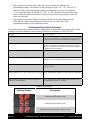
Simpler Is Better SST- 4 Installation and Operation Guide WiredRite Systems, Inc. www.wiredrite.com • [email protected] Contents SAFETY SUMMARY................................................................................................................2 INTRODUCTION......................................................................................................................3 OPERATIONAL FEATURES....................................................................................................4 CONNECTIONS........................................................................................................................5 INSTALLATION AND POWER-UP ........................................................................................6 PROGRAMMING . ...................................................................................................................7 Programming Procedure.............................................................................................8 TROUBLESHOOTING.............................................................................................................9 TEST MODE OPERATION:....................................................................................................11 Appendix I. Wiring diagrams ....................................................................................12 Appendix II. Connection Tables ..............................................................................16 Appendix III. REPLACEABLE PARTS..............................................................................17 Appendix IV. Truck Manufacturer Tech Support..........................................17 Appendix V. Auto stop on loss of pressure Mode..........................................18 SAFETY SUMMARY The following general safety precautions must be observed during all phases of operation, service, and repair of this instrument. Failure to comply with these precautions or with specific warnings elsewhere in this manual violates safety standards of design, manufacture, and intended use of the instrument. Wired Rite Systems assumes no liability for the customer’s failure to comply with these requirements. 1. SST-4 installation must be performed by appropriate qualified personnel trained for the installation of vehicle electrical equipment and controls for engine functions. 2. Vehicle safety interlocks installed in vehicles must never be bypassed. 3. Verify that the vehicle is disabled before performing installation or maintenance procedures with the SST-4. The battery should be disconnected to ensure that the vehicle is disabled during installation. 4. Whenever performing maintenance, use only factory specified parts and replacement parts. 5. Always use appropriate gauge wire for the expected current and power ratings. 6. DO NOT SUBSTITUTE PARTS OR MODIFY circuitry. Because of the danger of introducing additional hazards, do not install substitute parts or perform any unauthorized modification. 7. Equipment that appears damaged or defective should be made inoperative and secured against unintended operation until they can be repaired by qualified service personnel. Page © Wired Rite Systems, Inc. 800-538-7483 www.wiredrite.com Docsst-4-01.8 Rev 0 INTRODUCTION Thank you for purchasing the new SST-4 from Wired Rite Systems. This product has been designed for the highest reliability while providing your critical remote START-STOP-THROTTLE functions. The following items are included with the SST-4 shipment: SST-4 circuit board with optional enclosure or mounting base. Connector kits for wiring mating connectors to the six-pin connector and the two four-pin connectors. Part numbers for the connectors are shown in the replaceable parts section at the end of this manual. Figure 1. SST-4 in enclosure with cover removed © Wired Rite Systems, Inc. 800-538-7483 www.wiredrite.com Docsst-4-01.8 Rev 0 Page OPERATIONAL FEATURES Ability to remotely operate engine controls, including Start/Stop, Throttle and E-Power. Active and Inactive modes. Active mode when Master enable signal is provided to the SST-4. Auto Stop On Loss Of Pressure Mode allows the monitoring of engine or PTO functions and automatic fail-over to preset emergency power settings. Inputs triggers include: MASTER, Start/Stop (SS), Auxiliary (AUX), Throttle (TH), Pressure Sensor (PRESSURE) . Triggers are provided by supplying either a positive signal (+12V) or ground signal. Three replaceable on-board relays enable switching for Ignition, Start/Stop, and E-power. Circuit breakers provide protection for Ignition, Start/Stop, and E-Power circuits. Dual throttle relays allow for multiple throttle settings (engine speeds). Emergency power (E-Power) source can be triggered independently. Four character display showing faults, programming parameters and hour meter readout. LED status indicators provide additional information, such as status of relay positions. Programmable via 3-Pushbutton switches for choosing menu and entering/modifying parameters. No computer is required for programming. Timer delays can be set for the following: (Delay values are shown in Table 4) • E-Power Delay Timer • Throttle Delay Timer • Glow Plug Timer • Start Duration Timer (max cranking time of the vehicle’s starter). • Loss of engine oil/hydraulic fluid pressure sensor delay Maximum time for the E-Power circuit to be engaged can be set. Time values are shown in Table 4. Test mode allows bench testing of the inputs and outputs using built-in display. On-board self-diagnostic tests display faults, and system “remembers” any faults that have occurred, even if the faults no longer exist. Connector kits are included for control and throttle connectors. Pre-wired harnesses are available (optional). Page © Wired Rite Systems, Inc. 800-538-7483 www.wiredrite.com Docsst-4-01.8 Rev 0 CONNECTIONS Detailed wiring diagrams and notes are found in Appendix I. Please refer to that section for information and suggestions for your specific requirements. This manual assumes that the installation was completed using these suggestions. Figure 2 shows the SST-4 board layout, highlighting key components. Figure 3 shows the terminal connections for the wiring to the SST-4. Wiring diagrams. Wiring diagrams for common configurations of the SST-4 board are shown in Appendix I. Wiring diagrams. Connection tables. Tables showing the function of each connection to the SST-4 are shown in Appendix II. Connection Tables. Figure 2. SST-4 simplified board layout showing key components. TB1 T1 T2 J1 3 6 1 4 J1 INPUTS PIN 1 2 3 4 5 6 FUNCTION PRESSURE AUX TRIG MASTER THROTTLE START/STOP GROUND 1 2 3 4 5 TBI TSP 1 2 3 4 5 6 7 FUNCTION GROUND START OUT MAIN POWER (VBAT) AUX IN AUX OUT 6 2 1 2 1 4 3 4 3 7 T1 PIN 1 2 3 4 T2 FUNCTION RLY1 NORM.CLOSED RLY1 NORM.OPEN RLY1 NORM.CLOSED RLY1 NORM.OPEN PIN 1 2 3 4 FUNCTION RLY2 NORM.CLOSED RLY2 NORM.OPEN RLY2 NORM.CLOSED RLY2 NORM.OPEN IGNITION IN IGNITION OUT Figure 3. SST-4 Terminal connections. © Wired Rite Systems, Inc. 800-538-7483 www.wiredrite.com Docsst-4-01.8 Rev 0 Page INSTALLATION AND POWER-UP 1. After all of the connections have been made, and the unit has been mounted securely, the SST-4 is ready to be powered up. The following procedure describes the power up and initial checkout. 2. With the ignition switch in the ON position, turn on the “Master” switch to power up the SST-4. On initial power up the SST-4 will perform a self-diagnostic test to verify that all of the functions are operating correctly. If a flashing “SP” is reported, the master switch was turned on with the ignition switch in the off position. Turn on the iginition switch, and then hold down the UP and DOWN buttons simultaneously for 5 seconds to clear the fault. 3. If no faults are detected, the SST-4 will go into “Run mode” and the hour meter readout will be visible on the display (refer to Table 1). 4. If a fault is detected on power up, a code will be flashing on the display indicating in which circuit the fault has occurred. For assistance in troubleshooting, please refer to the trouble shooting section. 5. After all of the faults have been cleared and the SST-4 is operating in normal mode, apply signals to test the proper function of the SST-4. Table 1 outlines the different display codes and the operations which they indicate. Apply signals as available to ensure proper operation of each function.When checking signals, verify the status of various signals on the board by using the green display indicators, shown in and detailed in Table 2. Display Flashing Description Yes Board power only, Master switch is off. No Run mode (hour meter display) Note: If hour meter is counting, the decimal flashes. If not counting, decimal does not flash. No Stop mode No Start signal active, glow plugs on No Start signal active, starter on No Throttle Plunger input active No Emergency Power input active Table 1. Display during normal operations LED # On Indicates D3 Description Start/Stop or Throttle Input Throttle Relay #1 D4 Throttle Relay #2 Relay is enabled D5 Start Relay Relay is enabled, power at START OUT on TB1. D6 AUX Relay (E-Pump) Relay is enabled, power at AUX OUT on TB1. D7 Ignition Relay is enabled, power at IGN OUT on TB1. D2 An input trigger is applied to Start/Stop or Throttle Relay is enabled Table 2. SST-4 Green LED indicators. Page © Wired Rite Systems, Inc. 800-538-7483 www.wiredrite.com Docsst-4-01.8 Rev 0 PROGRAMMING Table 3. Programmable parameters and settings. *Denotes Factory Setting. † See timer notes Appendix VI Parameter Value “A” Plunger Mode “b” Throttle Mode (Only if A is set to 2) Description 1 Single plunger (Start/Stop only) 2* Dual plunger (Start/Stop/Throttle) 1* Throttle relays latch ON and OFF (maintained) 2 Throttle relays are momentary (on-demand) 3 T1 latches ON, T2 momentary, STOP turns both OFF 4 T1 & T2 latch ON, T2 OFF, STOP turns both OFF 5† Timed operation (see “E”) 6 T1 latches ON, T1 OFF & T2 latches ON, T1 & T2 OFF 7 T1 momentary ON, T2 momentary ON, repeat 8 1* No throttle mode As soon as MASTER Power is applied: T1 latches ON, T2 momentary, STOP turns both OFF As soon as MASTER Power is applied: T1 latches ON, T2 latches ON/OFF with Throttle input signal, STOP turns both OFF AUX (Emergency Power) from the J1 Pin 4 input (THROTTLE) 2 AUX (Emergency Power) from the J1 Pin 5 input (START/STOP) 3 RESERVED 4 AUX (Emergency Power) from J1 Pin 2 (AUX TRIG) 5 Auto Stop on Loss of Pressure Mode (see appendix V) 9† A† “C” AUX (Emergency Power) Mode “D” AUX (Emergency Power Time) “E” Throttle Mode Timer “F” Glow Plug Timer “H” Start Duration Timer “J” Emergency Power Duration Time 0-9, 3* Time delay for Emergency Power relay actuation, 0-9, 0* Time delay for throttle timed operation, 0-9, 0* Delay time for starter activation 0-9, 5* Maximum time for starter cranking 0-d, 8* Maximum time for Emergency Power operation “L” Diagnostic display On/Off 0* Diagnostic Display Off 1 Diagnostic Display On “o” Auto Stop Pressure Delay Timer 3-d, 7* “P” Pressure Switch Descriptor Pressure Sender delay time out when in Auto Stop Mode 0* Normally open and ground signal indicates pressure present. 1 Normally closed and ground signal indicates NO pressure. 2 Normally open and positive signal indicates pressure present. 3 Normally closed and positive signal indicates NO pressure, Table 4. Programmable Delay Timer Values Value 0 1 2 3 4 Delay Time No delay / timeout 1 second 2 seconds 3 seconds 5 seconds Value 5 6 7 8 9 Delay Time 10 seconds 15 seconds 20 seconds 30 seconds 45 seconds © Wired Rite Systems, Inc. 800-538-7483 www.wiredrite.com Value A b C d Delay Time 1 minute 2 minutes 3 minutes 4 minutes Docsst-4-01.8 Rev 0 Page Programming Procedure The following procedure describes how to view and change settings for SST-4 operation. These procedures require the user to access the pushbuttons on the SST-4 circuit board: “MENU”, “UP”, and “DOWN”. 1. Press the “MENU” button on the SST-4 board. The display will show the board’s current operating configuration, starting with “A2”, that is, the system is set for dual plunger mode. 2. Press “MENU” again, and the next parameter is displayed. Repeat pressing “MENU” to view all the settings, until the system returns to “A2”. 3. If changes are desired, press “MENU” until the target parameter is displayed. Use the “UP” and “DOWN” keys to change the parameter to the desired value. The available choices are those shown in Table 5. 4. To save changes, press and hold the “MENU” key for 5 seconds. The display flashes “SA” to confirm that the configuration change has been saved. If the configuration has been changed mistakenly, restore the SST-4 to its previous configuration by holding the “MENU” and “DOWN” keys for three seconds. This will reload the last saved settings. You can page through the configurations and see that it is as expected, then the settings must be saved, by holding the “MENU” key for 5 seconds. The display will flash “SA” for confirmation of the save. The SST-4 is preloaded with a factory default configuration. The default settings are displayed on Table 3 with an asterisk (*). To recall these setting hold the “MENU” and “UP” keys down together for 3 seconds. You can page through the configurations and see that it is as expected, then the settings must be saved, by pressing and holding the “MENU” key for 5 seconds. The display will flash “SA” as confirmation of the save. The table below shows a summary of the pushbutton controls. It is important to note that changes are not saved automatically, but must be written to memory by holding down the “MENU” key for 5 seconds. This includes any of the recall functions described above. The values that were recalled are not made active until the user has saved them. Table 5. Menu/Up/Down Pushbutton functions Function summary Function description Procedure Choose parameter Choose which parameter will be modified. Press “MENU” until the desired parameter is displayed. Choose value Choose the value of the selected parameter. Press “UP” and “DOWN” until the desired parameter value is displayed. Save changes Save the changes made to one or more parameter values. Press and hold “MENU” for 5 seconds. “SA” is flashed to confirm save. Recall previous Recall previously saved configuration and cancel last save command. Press and hold both “MENU” and “DOWN” for three seconds. “SA” is flashed to confirm save. Recall factory Recall factory settings for all parameters. Press and hold both “MENU” and “UP” for three seconds. “SA” is flashed to confirm save. Page © Wired Rite Systems, Inc. 800-538-7483 www.wiredrite.com Docsst-4-01.8 Rev 0 TROUBLESHOOTING If a problem is encountered, the following procedure can be used to troubleshoot the system, and identify and fix some of the more common problems. If the problem is not easily identified, please contact Wired Rite for assistance at 1-800-538-7483. Before beginning the troubleshooting, please check these five items: 1. System Lock-up. The processor on the SST-4 board can go into a locked-up situation if the power is toggled on and off at a rapid rate. If this occurs the processor must be reset by disconnecting the power to the board for several seconds and then reconnecting it. 2. Ground. The ground wire of the SST-4 must NOT be connected to the chassis, but routed directly to the negative side of the battery. 3. On-board LED indicators. An additional troubleshooting resource is the on-board LED indicators. These functions are described in Table 2. SST-4 Green LED indicators. 4. Diagnostic Display. If an error is detected by the SST-4, and parameter “L” is set to 1, the display will flash to identify the problem circuit. Refer to Table 6 for locating the cause of the fault. 5. Storing and clearing faults. If a fault occurs, the SST-4’s on board diagnostics will record in which circuit the fault occurred and save the fault into memory. To clear all of the recorded faults, press and hold the “UP” and “DOWN” buttons on the board for three seconds or remove board power. This will erase the volatile memory and place the system back in the “Run mode” Troubleshooting Procedure 1. Begin with all inputs to the board OFF. Remove the enclosure lid if present to allow visual inspection of the 4-character display and the relay status indicators. 2. Supply power to the SST-4 board. The 4-character displays should be active, for example with two blinking decimal points. Check for board power on TB1 pin 3 (GND is available on TB1 pin 1.) If there is no power, check the circuit breaker. 3. Turn the ignition ON. This should illuminate the relay indicators D5 (Starter Relay), D6 (Aux Relay), and D7 (Ignition Relay). If one or more indicators are not illuminated, then that circuit may not be receiving power from the ignition splice. Check the associated wiring path to ensure that the circuit is enabled. You may need to manually reset the manual circuit breakers near each relay by pressing the yellow tab. NOTE: The Aux Relay manual circuit breaker can be placed in two positions, depending on whether the system incorporates a separate E-power battery. If there is a separate E-power battery, then the circuit breaker should be connected between J5 and J6; otherwise it should be connected between J6 and J7. 4. Turn ON the SST-4 MASTER switch. This is sometimes labeled “MACHINE” or “PTO” or “AERIAL ENABLE” to indicate non-truck functions. This should activate the hour meter on the 4-character display. If not, check that the signal from the SST-4 MASTER signal is being applied to J1 Pin 3. 5. Apply START signal from the aerial switch. Indicator D2 should be illuminated. If not, verify that the START signal is being applied to J1 Pin 5. Remove the START signal. 6. Apply THROTTLE signal from the aerial switch. Indicator D2 should be illuminated. If not verify that the THROTTLE signal is being applied to J1 Pin 4. Remove the THROTTLE signal. © Wired Rite Systems, Inc. 800-538-7483 www.wiredrite.com Docsst-4-01.8 Rev 0 Page 7. Apply signal to activate the Start, Stop, and E-power functions as defined in the programming settings. Verify that the 4-character display shows “St”, “SP”, and “EP” as expected. If not, check programming settings (see Programming section). Set parameter “L” to 1 and if the display is flashing “St”, “SP”, or “EP”, then there has been a fault in that circuit. Check the manual circuit breakers and reset if necessary by pressing the yellow tab on the circuit breaker. 8. Apply signal to activate the Throttle functions as defined in the programming settings. Verify that the Throttle Relay Indicators D3 and D4 are activated. If not, check programming settings (see Programming section). Troubleshooting Quick Reference The following table shows common problems and possible solutions when operating the SST-4. If the problem is not easily identified, please contact Wired Rite for assistance at 1-800-538-7483. Problem Possible solution Nothing is displayed on 4-character display. Check board power available at TB1 pin 3. If power is applied and board is unresponsive, try resetting processor by removing system power for at least three seconds. Then reapply power. Relay Indicators D5, D6, D7 off with Ignition on. Check Ignition Splice. Check manual circuit breakers. Check position of Aux Relay circuit breaker. With separate E-power battery, circuit breaker should be between J5 and J6. Otherwise it should be between J6 and J7. No HOUR METER is displayed on 4-character display. Check board power and SST-4 Master input at J1 Pin 3. HOUR METER is not counting (decimal not flashing) Check SST-4 Master input at J1 Pin 3. Check Programming Parameter “o” for Hour Meter Input mode (Master or Spare). Start/Stop or Throttle inputs do not activate D2 indicator. Check signal path for trigger signals Start/Stop (J1 Pin 5) and Throttle (J1 Pin 4). Displayed state of “St”, “SP” or “EP” are not as expected Check Programming Parameters C and D and timer durations. Throttle Relay not triggering and Relay Indicators D3 and D4 are not illuminated. Check signal path for Throttle signals into T1 and T2. Check Programming Parameters A, B, and E. Table 6. Fault Display Flashing Display Description Fault detected in Stop circuit Fault detected in Start circuit Fault detected in Emergency Power circuit Page 10 © Wired Rite Systems, Inc. 800-538-7483 www.wiredrite.com Docsst-4-01.8 Rev 0 TEST MODE OPERATION: Test Mode is used to verify the wiring and operation of the system. CAUTION: when in Test Mode, the vehicle or Emergency Pump may start unexpectedly. Whenever possible, Test Mode should be used for bench testing. If used when installed, two mechanics should be present, and extra care is strongly advised. To enter Test Mode, press and hold all three buttons: “MENU”, “UP”, and “DOWN” for five seconds until all of the segments flash in the middle two 7-segment displays. To verify each of the items shown in the table below, perform the user action, and verify the resulting display. Verification Of Relay Functions User Action Ignition relay & T1 Throttle relay With ignition ON press MENU button on SST-4 board (WARNING: Vehicle may start) Starter relay & T2 Throttle relay With ignition ON press Up button on SST-4 board (WARNING: Vehicle may start) Emergency Pump relay With ignition ON press Down button on SST-4 board (WARNING: E-Pump may start) Verification Of Installation Wiring User Action Board Power (TB1, Position 3) Apply power to board Ignition Power (TB1, Position 6) Turn ignition key ON Power from Master switch (J1, Pin 3) Turn ON Master switch Remote E-Power input (J1, Pin 2) Activate remote E-power switch Remote Start/Stop input (J1, Pin 5) Activate remote Start/Stop switch Remote Throttle input (J1, Pin 4) Activate remote Throttle switch © Wired Rite Systems, Inc. 800-538-7483 www.wiredrite.com Resulting Display Resulting Display Docsst-4-01.8 Rev 0 Page 11 Appendix I. Wiring diagrams The SST-4 can be wired in various ways for a variety of engine control applications. This section includes wiring diagram for three common configurations: 1. Aux E-Power Battery. Emergency Power is provided from an Auxiliary Battery. Programming state would include “C4”. 2. No Aux E-Power Battery. Emergency Power is provided from normal battery (there is no Auxiliary Battery) and E-power control is from Start/Stop or Throttle signals. Programming state would include “C1” or “C2”. 3. No Aux E-Power Battery, simplified. Fully ignition supplied. Emergency Power is provided from normal battery (there is no Auxiliary Battery) and E-power control is from Start/Stop or Throttle signals. Programming state would include “C1” or “C2”. TB1 T1 T2 J1 3 6 1 4 J1 INPUTS PIN 1 2 3 4 5 6 FUNCTION PRESSURE AUX TRIG MASTER THROTTLE START/STOP GROUND 1 2 3 4 5 TBI TSP 1 2 3 4 5 6 7 FUNCTION GROUND START OUT MAIN POWER (VBAT) AUX IN AUX OUT 6 T1 PIN 1 2 3 4 2 1 2 1 4 34 3 7 T2 FUNCTION PIN FUNCTION RLY1 NORM.CLOSED 1 RLY2 NORM.CLOSED RLY1 NORM.OPEN 2 RLY2 NORM.OPEN RLY1 NORM.CLOSED 3 RLY2 NORM.CLOSED RLY1 NORM.OPEN 4 RLY2 NORM.OPEN IGNITION IN IGNITION OUT Connection Notes 1. The Auxiliary (AUX), Throttle (TH), and Start/Stop (SS) are input triggers that are provided by supplying either a positive signal (+12V) or ground signal. 2. Emergency Power operation: If using a separate E-Power Battery, the circuit breaker for the AUX relay on the SST-4 must be connected between the J6 and J5 female push-on connectors. If a separate E-Power battery is NOT being used, the circuit breaker must be connected between the J6 and J7 connectors. See Figure 2 for connection locations. Page 12 © Wired Rite Systems, Inc. 800-538-7483 www.wiredrite.com Docsst-4-01.8 Rev 0 Wiring Diagram 1 Aux E-Power Battery. Emergency Power is provided from Auxiliary Battery. Note center Circuit Breaker is positioned in the J6-J5 location. EMERGENCY HYDRAULIC PUMP SOLINOID D2 STARTER D5 MENU UP DOWN IGNITION D3 D4 AUX. D6 D7 START/STOP E-POWER THROTTLE AIR CYLINDER AIR CYLINDER AIR CYLINDER AUX. STARTER E-PUMP IGNITION J1 20A RED/WHT (J1 PIN-3) T1 T2 20A TB1 1 7 CIRCUIT BREAKER WHT- GND ORG/BLK- STARTER RED-VBAT RED/GRN-AUX BAT PUR/GRN-AUX OUT ORG-IGN IN ORG/RED-IGN OUT PRESSURE SWITCHES BATTERY +12 VOLTS MASTER SWITCH 20A AUXILIARY BATTERY REFER TO ENGINE ECM DOCUMENTATION FOR WIRING INSTRUCTIONS WHT/YEL (J1 PIN-4) WHT/BLU (J1 PIN-5) WHT/GRN (J1 PIN-2) IGNITION ELECTRONIC CONTROL MODULE INSTALLER MUST CUT EXISTING IGNITION WIRE HERE WRS PART# CBW 1081 EXISTING 80 AMP BREAKER EXISTING ACC BATTERY ON START EXISTING + STARTER TB1 VEHICLE BATTERY J1 3 6 1 4 J1 INPUTS PIN 1 2 3 4 5 6 FUNCTION PRESSURE AUX TRIG MASTER THROTTLE START/STOP GROUND 1 2 3 4 5 TBI TSP 1 2 3 4 5 6 7 STARTER T1 T2 FUNCTION GROUND START OUT MAIN POWER (VBAT) AUX IN AUX OUT 6 2 1 2 1 4 3 4 3 T1 PIN 1 2 3 4 SOLENOID 7 FUNCTION RLY1 NORM.CLOSED RLY1 NORM.OPEN RLY1 NORM.CLOSED RLY1 NORM.OPEN T2 PIN 1 2 3 4 FUNCTION RLY2 NORM.CLOSED RLY2 NORM.OPEN RLY2 NORM.CLOSED RLY2 NORM.OPEN IGNITION IN IGNITION OUT © Wired Rite Systems, Inc. 800-538-7483 www.wiredrite.com Docsst-4-01.8 Rev 0 Page 13 Wiring Diagram 2 No Aux E-Power Battery, power supplied from main battery through waterproof circuit breaker. Emergency Power is provided from normal battery (there is no Auxiliary Battery) and E-power control is from Start/Stop or Throttle signals. Programming state would include “C1” or “C2”. EMERGENCY HYDRAULIC PUMP SOLINOID D2 STARTER D5 D6 STARTER J1 RED/WHT (J1 PIN-3) D7 START/STOP THROTTLE AIR CYLINDER AIR CYLINDER AUX. E-PUMP IGNITION 20A 20A T1 T2 20A TB1 1 7 WHT- GND ORG/BLK- STARTER RED-VBAT PUR/GRN-AUX OUT ORG-IGN IN ORG/RED-IGN OUT PRESSURE SWITCHES BATTERY +12 VOLTS MASTER SWITCH MENU UP DOWN IGNITION D3 D4 AUX. REFER TO ENGINE ECM DOCUMENTATION FOR WIRING INSTRUCTIONS WHT/YEL (J1 PIN-4) WHT/BLU (J1 PIN-5) IGNITION ELECTRONIC CONTROL MODULE INSTALLER MUST CUT EXISTING IGNITION WIRE HERE WRS PART# CBW 1081 EXISTING 80 AMP BREAKER EXISTING EXISTING + TB1 3 6 VEHICLE BATTERY 1 4 J1 INPUTS PIN 1 2 3 4 5 6 FUNCTION PRESSURE AUX TRIG MASTER THROTTLE START/STOP GROUND 1 2 3 4 5 TBI TSP 1 2 3 4 5 6 7 STARTER T1 T2 J1 Page 14 ACC BATTERY ON START FUNCTION GROUND START OUT MAIN POWER (VBAT) AUX IN AUX OUT 6 2 1 2 1 4 3 4 3 T1 PIN 1 2 3 4 STARTER 7 FUNCTION RLY1 NORM.CLOSED RLY1 NORM.OPEN RLY1 NORM.CLOSED RLY1 NORM.OPEN SOLENOID T2 PIN 1 2 3 4 FUNCTION RLY2 NORM.CLOSED RLY2 NORM.OPEN RLY2 NORM.CLOSED RLY2 NORM.OPEN IGNITION IN IGNITION OUT © Wired Rite Systems, Inc. 800-538-7483 www.wiredrite.com Docsst-4-01.8 Rev 0 Wiring Diagram 3 No Aux E-Power Battery, simplified. Power supplied from main battery through ignition switch circuit. Please note that this circuit puts extra demand on the ignition circuit. Wire of sufficient gauge must be used. Check your vehicle electrical specifications to be certain that his circuit will not damage the ignition system. Emergency Power is provided from normal battery (there is no Auxiliary Battery) and E-power control is from Start/Stop or Throttle signals. Programming state would include “C1” or “C2”. EMERGENCY HYDRAULIC PUMP SOLINOID D2 STARTER D5 AUX. D6 STARTER 20A RED/WHT (J1 PIN-3) WHT- GND ORG/BLK- STARTER INSTALLER SUPPLIED WIRE BATTERY +12 VOLTS 20A START/STOP THROTTLE AIR CYLINDER AIR CYLINDER T1 T2 20A TB1 1 MASTER SWITCH D7 AUX. E-PUMP IGNITION 7 PRESSURE SWITCHES PUR/GRN-AUX OUT ORG-IGN IN ORG/RED-IGN OUT J1 MENU UP DOWN IGNITION D3 D4 REFER TO ENGINE ECM DOCUMENTATION FOR WIRING INSTRUCTIONS WHT/YEL (J1 PIN-4) WHT/BLU (J1 PIN-5) IGNITION ELECTRONIC CONTROL MODULE INSTALLER MUST CUT EXISTING IGNITION WIRE HERE EXISTING EXISTING ACC BATTERY ON START EXISTING + STARTER TB1 VEHICLE BATTERY J1 3 6 1 4 J1 INPUTS PIN 1 2 3 4 5 6 FUNCTION PRESSURE AUX TRIG MASTER THROTTLE START/STOP GROUND 1 2 3 4 5 6 TBI TSP 1 2 3 4 5 6 7 STARTER T1 T2 FUNCTION GROUND START OUT MAIN POWER (VBAT) AUX IN AUX OUT 2 1 2 1 4 3 4 3 T1 PIN 1 2 3 4 SOLENOID 7 T2 FUNCTION RLY1 NORM.CLOSED RLY1 NORM.OPEN RLY1 NORM.CLOSED RLY1 NORM.OPEN PIN 1 2 3 4 FUNCTION RLY2 NORM.CLOSED RLY2 NORM.OPEN RLY2 NORM.CLOSED RLY2 NORM.OPEN IGNITION IN IGNITION OUT © Wired Rite Systems, Inc. 800-538-7483 www.wiredrite.com Docsst-4-01.8 Rev 0 Page 15 Appendix II. Connection Tables 1. Ignition relay on SST-4 is “Normally Closed”. If power is not supplied to the board, the ignition circuit will be closed and the ignition function will not be interrupted. 2. The SST-4 hour meter can be triggered either by the MASTER signal or the SPARE signal on J1 Pin 1. This is user-programmable, as described in Section 5. PROGRAMMING. 3. T1 and T2 are identical, except T1 controls Relay 1 and T2 controls Relay2. TB1 T1 T2 J1 3 6 1 4 J1 INPUTS PIN 1 2 3 4 5 6 FUNCTION PRESSURE AUX TRIG MASTER THROTTLE START/STOP GROUND 1 2 3 4 5 TBI TSP 1 2 3 4 5 6 7 FUNCTION GROUND START OUT MAIN POWER (VBAT) AUX IN AUX OUT 6 2 1 2 1 4 3 4 3 7 T1 PIN 1 2 3 4 T2 FUNCTION RLY1 NORM.CLOSED RLY1 NORM.OPEN RLY1 NORM.CLOSED RLY1 NORM.OPEN PIN 1 2 3 4 FUNCTION RLY2 NORM.CLOSED RLY2 NORM.OPEN RLY2 NORM.CLOSED RLY2 NORM.OPEN IGNITION IN IGNITION OUT J1 Connections J1# Label Function Vehicle Wire Label 1 PRESSURE Pressure sensor trigger input. Engine oil or PTO hydraulic fluid sensor. PRESSURE 2 AUX TRIGGER E-Pump switch AUX TRIG 3 MASTER Triggers Auxiliary circuitry used for Epower Enables SST-4 operation and triggers onboard hour meter Master enable switch MASTER POS 4 THROTTLE Triggers throttle circuitry on SST-4 board Bucket Throttle switch THROTTLE 5 START/STOP Bucket Start/Stop switch START TRIG 6 GROUND Triggers Start/Stop circuitry on SST-4 board Ground (Use negative battery connection, not vehicle chassis.) Battery (-) GND TB1 Connections TB1 Pin# Label 1 GND 2 START OUT 3 VBAT 4 AUX IN 5 AUX OUT 6 IGN IN 7 IGN OUT Function Vehicle Ground (Use negative battery connection, not vehicle chassis.) Wire Label (typical) Battery (-) GND Supplies power to starter when relay is enabled Output from key “Start” STARTER Supplies +12V to board in normal operation Battery (+) VBAT Auxiliary input. May be used for Emergency Power or other user defined function. Auxiliary output supplies high current output to E-pump or other function when relay is enabled E-Power battery AUX BAT E-Pump AUX OUT Ignition input signal. Key side of ignition splice ECM side of ignition splice IGN IN Ignition output IGN OUT T1 & T2 Connections T1 Pin 1 2 3 4 T1 Pin 1 2 3 4 Page 16 Label RLY1 N.C. RLY1 N.O. RLY1 N.C. RLY1 N.O. Label RLY2 N.C. RLY2 N.O. RLY2 N.C. RLY2 N.O. Function Common to throttle control relay one, Normally Closed Common to throttle control relay one, Normally Open Output from throttle control relay one, Normally Closed Output from throttle control relay one, Normally Open Function Common to throttle control relay two, Normally Closed Common to throttle control relay two, Normally Open Output from throttle control relay two, Normally Closed Output from throttle control relay two, Normally Open Vehicle Throttle Circuit Throttle Circuit Throttle Circuit Throttle Circuit Vehicle Throttle Circuit Throttle Circuit Throttle Circuit Throttle Circuit © Wired Rite Systems, Inc. 800-538-7483 www.wiredrite.com Wire Label RLY 1 NC RLY 1 NO RLY 1 NC RLY 1 NO Wire Label RLY 2 NC RLY 2 NO RLY 2 NC RLY 2 NO Docsst-4-01.8 Rev 0 Appendix III. REPLACEABLE PARTS The following are replaceable parts on the SST-4. To order please see website at http://store.wiredrite. com/store. WRS # DESCRIPTION AMP # QTY CBA1031 Circuit Breaker 3 RLY1164 Relay 3 CON7135 Amp, Mini Mate N’ Loc 6 Pos. Plug 172168-1 1 CON7120 Amp, Mini Mate N’ Loc 4 Pos. Plug 172167-1 2 CON7125 AMP, Mini Mate N’ Loc Socket 171639-1 14 Appendix IV. Truck Manufacturer Tech Support Additional information from the truck manufacturers is provided in the references below: General Motors: www.gmupfitter.com Hotline 800-875-4742 Ford Motor Company: www.fleet.ford.com Cummins: www.cummins.com Customer Assistance 1-800-DIESELS (1-800-343-7357) International: www.internationaldelivers.com Tech Central Help Line 1-800-448-7825 Freightliner: www.freightlinertrucks.com © Wired Rite Systems, Inc. 800-538-7483 www.wiredrite.com Docsst-4-01.8 Rev 0 Page 17 Appendix V. Auto stop on loss of pressure Mode This mode will force the SST-4 into STOP mode if loss of pressure is detected on a userinstalled circuit. This will then allow the user-specified stop mode settings to control. This mode is especially useful in the situation where the vehicle stalls and the e-pump must be used to control the aerial device. Setting the SST-4 and supplying a pressure switch to monitor either the engine oil or the PTO hydraulic pressure will permit an automatic fail-over to the e-pump without operator intervention. Two inputs are used: the MASTER (J1 pin 3) input, usually connected to a switch controlled by the operator to activate the SST-4, and the PRESSURE (J1 pin 1) input, which should be connected to a pressure switch that senses either engine oil or hydraulic fluid pressure. When in this mode, and pressure is lost, the SST-4 will be forced into STOP mode after the delay specified in parameter “o”. Since there are many different types of pressure switches available in the market, parameter “P” is used to describe how your particular switch functions. When the system is in this mode, the hour meter counts only when both the MASTER input and the PRESSURE input are true. The pressure switch may be installed to measure either engine oil pressure or PTO hydraulic fluid pressure. If the switch is on the PTO, it is possible that the truck will be stopped automatically if the operator-controlled master switch is turned on, but the operator does not engage the PTO before the time out interval specified in parameter “o”. For this reason, it is strongly suggested that the MASTER and PTO function be combined onto one switch. Be certain to specify a delay interval in parameter “o” of sufficient duration to allow any other timers to complete. This is especially true if you are utilizing parameter “F” (Glow Plug Delay) as it is possible to set up a situation where the vehicle can never be restarted if “F” is set to a period longer than “o”. Appendix VI. Timer Notes By using Menu “E - Throttle Mode Timer,” a delay can be created to use with the parameters of Menu b marked with a †. Parameter 5, Timed Operations: (start with T1 & T2 OFF) Throttle trigger input > Menu “E” Delay > T1 ON Next Throttle trigger input > Menu “E” Delay > T1 OFF, T2 ON Next Throttle trigger input > Menu “E” Delay > T1 & T2 ON Next Throttle trigger input > Menu “E” Delay > T1 & T2 OFF REPEAT cycle Parameter 9: As soon as MASTER power is applied > Menu “E” Delay > T1 latches ON Throttle trigger input > NO DELAY, then T2 momentary REPEAT cycle without delay until STOP mode is entered, then the DELAY is activated again Parameter A: As soon as MASTER power is applied > Menu “E” Delay > T1 latches ON Throttle trigger input > NO DELAY, then T2 Latches ON Next Throttle trigger input > NO DELAY, then T2 Latches OFF REPEAT cycle without delay until STOP mode is entered, then the DELAY is activated again Page 18 © Wired Rite Systems, Inc. 800-538-7483 www.wiredrite.com Docsst-4-01.8 Rev 0 NOTES © Wired Rite Systems, Inc. 800-538-7483 www.wiredrite.com Docsst-4-01.8 Rev 0 Page 19 © 2006 Wired Rite Systems, Inc. 5793 Skylane Blvd Windsor, CA 95492 800.538.7483 Fax: 707.838.1050 [email protected] www.wiredrite.com