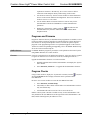
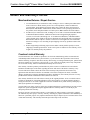
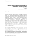
1
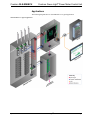
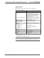
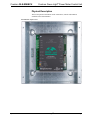
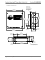
Crestron GLS-EM-MCU ® Crestron Green Light Power Meter Control Unit Operations Guide This document was prepared and written by the Technical Documentation department at: Regulatory Compliance This product is Listed to applicable UL Standards and requirements by Underwriters Laboratories Inc. As of the date of manufacture, the GLS-EM-MCU has been tested and found to comply with specifications for CE marking and standards per EMC and Radiocommunications Compliance Labelling. Federal Communications Commission (FCC) Compliance Statement This device complies with part 15 of the FCC Rules. Operation is subject to the following conditions: (1) This device may not cause harmful interference and (2) this device must accept any interference received, including interference that may cause undesired operation. CAUTION: Changes or modifications not expressly approved by the manufacturer responsible for compliance could void the user’s authority to operate the equipment. NOTE: This equipment has been tested and found to comply with the limits for a Class B digital device, pursuant to part 15 of the FCC Rules. These limits are designed to provide reasonable protection against harmful interference in a residential installation. This equipment generates, uses and can radiate radio frequency energy and, if not installed and used in accordance with the instructions, may cause harmful interference to radio communications. However, there is no guarantee that interference will not occur in a particular installation. If this equipment does cause harmful interference to radio or television reception, which can be determined by turning the equipment off and on, the user is encouraged to try to correct the interference by one or more of the following measures: • Reorient or relocate the receiving antenna • Increase the separation between the equipment and receiver • Connect the equipment into an outlet on a circuit different from that to which the receiver is connected • Consult the dealer or an experienced radio/TV technician for help Industry Canada (IC) Compliance Statement This Class B digital apparatus complies with Canadian ICES-003. Cet appareil numérique de la classe B est conforme à la norme NMB-003 du Canada. The specific patents that cover Crestron products are listed at patents.crestron.com. Crestron, the Crestron logo, Crestron Green Light, Crestron Toolbox and Fusion EM are either trademarks or registered trademarks of Crestron Electronics, Inc. in the United States and/or other countries. UL and the UL logo are either trademarks or registered trademarks of Underwriters Laboratories, Inc. in the United States and/or other countries. Windows is either a trademark or registered trademark of Microsoft Corporation in the United States and/or other countries. Other trademarks, registered trademarks, and trade names may be used in this document to refer to either the entities claiming the marks and names or their products. Crestron disclaims any proprietary interest in the marks and names of others. ©2012 Crestron Electronics, Inc. Crestron GLS-EM-MCU Crestron Green Light® Power Meter Control Unit Contents Crestron Green Light® Power Meter Control Unit: GLS-EM-MCU 1 Introduction ............................................................................................................................... 1 Features and Functions ................................................................................................ 1 Applications................................................................................................................. 3 Specifications .............................................................................................................. 4 Physical Description .................................................................................................... 5 Setup ........................................................................................................................................ 10 Identity Code ............................................................................................................. 10 Installation and Wiring .............................................................................................. 10 Hardware Hookup ..................................................................................................... 10 Programming Software ............................................................................................................ 11 Earliest Version Software Requirements for the PC ................................................. 11 Programming with SIMPL Windows ........................................................................ 11 Uploading and Upgrading ........................................................................................................ 13 Establishing Communication ..................................................................................... 13 Programs and Firmware ............................................................................................ 14 Program Checks ........................................................................................................ 14 Configuration ........................................................................................................................... 15 Recording Interval ..................................................................................................... 15 Electrical Tab ............................................................................................................ 15 Pulse Metering Tab.................................................................................................... 15 Problem Solving ...................................................................................................................... 16 Troubleshooting......................................................................................................... 16 Reference Documents ................................................................................................ 16 Further Inquiries ........................................................................................................ 16 Future Updates .......................................................................................................... 16 Return and Warranty Policies .................................................................................................. 18 Merchandise Returns / Repair Service ...................................................................... 18 Crestron Limited Warranty........................................................................................ 18 Operations Guide – DOC. 7294B Contents • i Crestron Green Light® Power Meter Control Unit Crestron GLS-EM-MCU ® Crestron Green Light Power Meter Control Unit: GLS-EM-MCU Introduction The GLS-EM-MCU is an Ethernet-based power metering control unit, designed to log overall electricity usage in real time. It measures and tracks actual energy consumption by attaching to the incoming electrical service and branch circuits. The GLS-EM-MCU also works in unison with the GLS-EM-CTI and GLS-EM-CT to provide more detailed data by tracking individual branch circuits in a home or office. This data is then displayed on a touch screen, mobile device or computer for viewing by users. Additionally, the GLS-EM-MCU system interfaces with Fusion EM™ Energy Management Software to provide reports with greater detail showing total building consumption. Features and Functions • • • • • • • Power metering across 3 phases (main legs) Reports data to control system and Fusion EM™ Monitors and logs RMS voltage, current, and active power Monitors up to 84 individual branch circuits for more detailed data Installs next to electrical panel Operable with 100-347 Volt, 2- and 3-phase systems Non-volatile memory reliably stores internally logged data Three-Phase Monitoring The main control unit (MCU) monitors both voltage and current to provide complete statistics of a building's electricity consumption. To achieve this, the MCU connects to line voltage of each phase (up to three) and neutral. Current transformers (GLS-EM-CTs) clamp around each of the incoming feed wires. These CTs then wire into the MCU's inputs. With the voltage and current data, the MCU calculates power usage. Individual Branch Monitoring In many cases, users may want to monitor consumption by area, or even device. The main control unit, in conjunction with the current transformer interface, enables metering of multiple branch circuits. GLS-EM-CT current transformers are placed Operations Guide – DOC. 7294B ® Crestron Green Light Power Meter Control Unit: GLS-EM-MCU • 1 Crestron Green Light® Power Meter Control Unit Crestron GLS-EM-MCU around the feed wire of each circuit, and then connected to the GLS-EM-CTI current transformer interfaces. Up to four GLS-EM-CTI can connect to a single GLS-EM-MCU for monitoring of up to 84 branch circuits. Current Transformers Current transformers are vital to metering power. Crestron® offers various split-core models that work with 600, 400, and 200 Amp feeds; these devices clamp around main feeds. Solid-core models exist for 50 and 20 Amp circuits; the wire must be routed through the closed loop of the core. Real-time and Logged Data Inherent to the GLS-EM-MCU is the ability to provide both real-time and logged power usage data. Real-time data can be used on touch screens or lobby displays to show instantaneous usage. The energy usage screen within Fusion EM software provides attractive charts and graphs that illustrate the facility's energy consumption. Additionally, logged data can be shared with Fusion EM for more detailed reporting. The GLS-EM-MCU stores the logged data in non-volatile memory to prevent data loss. ® 2 • Crestron Green Light Power Meter Control Unit: GLS-EM-MCU Operations Guide – DOC. 7294B Crestron GLS-EM-MCU Crestron Green Light® Power Meter Control Unit Applications The following diagram shows a GLS-EM-MCU in a typical application. GLS-EM-MCU in a Typical Application Operations Guide – DOC. 7294B ® Crestron Green Light Power Meter Control Unit: GLS-EM-MCU • 3 Crestron Green Light® Power Meter Control Unit Crestron GLS-EM-MCU Specifications Specifications for the GLS-EM-MCU are listed in the following table. GLS-EM-MCU Specifications SPECIFICATION DETAILS Wired Communications Ethernet 10/100 Mbps; auto-switching; autonegotiating; auto-discovery; full/half duplex; industry-standard TCP/IP stack; UDP/IP; CIP; DHCP; IPv4; installer setup via Crestron Toolbox™ Branch Circuit Monitor Bus Addressable data bus for connecting MCU to CTI units; transfers value provided by CT connected to CTI Operating Voltage 100 to 347 Volts AC, 50/60Hz Minimum 2-Series Control 1,2 System Update File Version 4.003.0007 or later Enclosure Galvanized steel with powder coat finish Environmental Installation Location Indoor use only Temperature 32º to 104º F (0º to 40º C) Humidity 0% to 95% RH (non-condensing) Heat Dissipation 10 BTU/Hr Dimensions Height 10 1/4 in (260 mm) Width 10 3/16 in (260 mm) Depth 3 7/16 in (88 mm) Weight 64 oz (1.8 kg) 1. The latest software versions can be obtained from the Crestron Web site. Refer to the NOTE following these footnotes. 2. Crestron 2-Series control systems include the AV2 and PRO2. Consult the latest Crestron Product Catalog for a complete list of 2-Series control systems. NOTE: Crestron software and any files on the Web site are for authorized Crestron dealers and Crestron Authorized Independent Programmers (CAIPs) only. New users must register to obtain access to certain areas of the site (including the FTP site). ® 4 • Crestron Green Light Power Meter Control Unit: GLS-EM-MCU Operations Guide – DOC. 7294B Crestron GLS-EM-MCU Crestron Green Light® Power Meter Control Unit Physical Description This section provides information on the connections, controls and indicators available on the GLS-EM-MCU. GLS-EM-MCU Physical View Operations Guide – DOC. 7294B ® Crestron Green Light Power Meter Control Unit: GLS-EM-MCU • 5 Crestron Green Light® Power Meter Control Unit Crestron GLS-EM-MCU GLS-EM-MCU Overall Dimensions (8x) Ø 3/16 in (Ø 6 mm) Wall Mounting Holes for #8 or #10 Screws (Not Supplied) 10 3/16 in (260 mm) 10 1/4 in (260 mm) 7 3/4 in (196 mm) Both Ends 7 in (178 mm) Both Ends 3 3/4 in (96 mm) Both Ends 3/8 in (10 mm) 1 1/4 in (32 mm) 10 1/8 in (257 mm) 2 11/16 in (69 mm) 1 11/16 in (43 mm) 6 in (153 mm) Both Ends 2 1/16 in (53 mm) 2 7/16 in (62 mm) 2 in (51 mm) 3 3/16 in (81 mm) 3 7/16 in (88 mm) 1 11/16 in (44 mm) 7 1/2 in (191 mm) Both Ends 1 5/16 in (34 mm) ® 6 • Crestron Green Light Power Meter Control Unit: GLS-EM-MCU 3/16 in (5 mm) (12x) Knockouts for 1/2 in (13 mm) Conduit Operations Guide – DOC. 7294B Crestron GLS-EM-MCU Crestron Green Light® Power Meter Control Unit GLS-EM-MCU Overall Dimensions (Cover Removed) (4x) Ø 1/4 in (Ø 7 mm) Wall Mounting Holes for #10 Screws (Not Supplied) Ground Bus All Mating Connectors Furnished with Unit 7 1/8 in (181 mm) 10 1/8 in (257 mm) 1 1/2 in (38 mm) 1 9/16 in (40 mm) Operations Guide – DOC. 7294B 7 in (178 mm) ® Crestron Green Light Power Meter Control Unit: GLS-EM-MCU • 7 Crestron Green Light® Power Meter Control Unit Crestron GLS-EM-MCU Connectors, Controls & Indicators Connectors, Controls & Indicators # CONNECTORS*, CONTROLS & INDICATORS 1 NEUT 2 LINE1 – LINE3 3 CT1 – CT3 4 BRANCH CIRCUIT MONITORS DESCRIPTION (1) terminal block, neutral input (3) terminal blocks, line input for each of three separate phases (3) 2-pin detachable terminal block, input for main leg current transformer (1) 8-pin detachable terminal block to be attached to a current transformer interface (GLS-EM-CTI) (Continued on following page) ® 8 • Crestron Green Light Power Meter Control Unit: GLS-EM-MCU Operations Guide – DOC. 7294B Crestron Green Light® Power Meter Control Unit Crestron GLS-EM-MCU Connectors, Controls & Indicators (Continued) * Operations Guide – DOC. 7294B # CONNECTORS*, CONTROLS & INDICATORS DESCRIPTION 5 LINE1 – LINE3 LEDs (3) Green LEDs, indicate line voltage is present on each input LINE1 through LINE3 CT1 – CT3 LEDs (3) Green LEDs, indicate current is flowing through CTs connected to ports CT1 through CT3 6 PULSE INPUTS 1-4 (1) 8-pin 3.5 mm detachable terminal block comprising (4) programmable digital inputs (referenced to GND); Input Voltage Range: 0-24 Volts DC; Logic Threshold: ≥1.25 Volts DC active/high, ≤0.46 Volt DC inactive/low; Frequency Range: 0.05 - 100 Hz 7 USB 8 RESET (1) Push button for hardware reset 9 SETUP (1) Miniature push button for setup; (1) Red LED, indicates device is in Setup mode 10 NET (1) Yellow LED, indicates communication to one or more GLS-EM-CTI 11 LAN (1) 8-wire RJ-45 jack (8P8C modular female); 10BASE-T/100BASE-TX Ethernet port (1) USB Type B console port, for communication with Crestron Toolbox™ Interface connectors for BRANCH CIRCUIT MONITORS, CT1 – CT3, and INPUTS 1-4 ports are provided with the unit. ® Crestron Green Light Power Meter Control Unit: GLS-EM-MCU • 9 Crestron Green Light® Power Meter Control Unit Crestron GLS-EM-MCU Setup Identity Code The IP ID is set within the GLS-EM-MCU’s IP table using Crestron Toolbox™. For information on setting an IP table, refer to the Crestron Toolbox help file. The IP IDs of multiple GLS-EM-MCU devices in the same system must be unique. When setting the IP ID, consider the following: • The IP ID of each unit must match an IP ID specified in the SIMPL Windows program. • Each device using IP to communicate with a control system must have a unique IP ID. Installation and Wiring For details on installation and wiring, refer to the latest version of the GLS-EM-MCU Installation Guide (Doc. 7295), which is available from the Crestron Web site (www.crestron.com/manuals). Hardware Hookup Make the necessary connections as called out in the illustration that follows this paragraph. Apply power after all connections have been made. When making connections to the GLS-EM-MCU, note that the included cable cannot be extended. Hardware Connections for the GLS-EM-MCU NEUT & LINE 1 - 3: Neutral and Line Connections from Main Power Supply PULSE INPUTS: From Programmable Digital Inputs CT1 - 3: Input for Main Leg Current Transformers USB: To PC for Initial Setup and Programming LAN: 10BASE-T/ 100BASE-TX Ethernet to LAN BRANCH CIRCUIT MONITORS: From GLS-EM-CTI Current Transformer Interface (Supplied Separately) NOTE: To prevent overheating, do not operate this product in an area that exceeds the environmental temperature range listed in the table of specifications. ® 10 • Crestron Green Light Power Meter Control Unit: GLS-EM-MCU Operations Guide – DOC. 7294B Crestron Green Light® Power Meter Control Unit Crestron GLS-EM-MCU Programming Software Have a question or comment about Crestron software? Answers to frequently asked questions (FAQs) can be viewed in the Online Help section of the Crestron Web site. To post a question or view questions submitted to Crestron’s True Blue Support, log in at www.crestron.com/onlinehelp. First-time users must establish a user account to fully benefit from all available features. Software Requirements for the PC NOTE: The latest software can be downloaded from the Crestron Web site (www.crestron.com/software). Crestron provides an assortment of Windows-based software tools to develop a customized system. Use SIMPL Windows to create a program to control the GLS-EM-MCU. Programming with SIMPL Windows SIMPL Windows is Crestron’s premier software for programming Crestron control systems. It is organized into two separate but equally important “Managers”: Configuration and Program. Configuration Manager Configuration Manager is the view where programmers “build” a Crestron control system by selecting hardware from the Device Library. 1. To incorporate the GLS-EM-MCU into the system, drag the GLS-EM-MCU from the Lighting | Lighting (Green Light Series) folder of the Device Library and drop it in the System Views. Locating the GLS-EM-MCU in the Device Library Operations Guide – DOC. 7294B ® Crestron Green Light Power Meter Control Unit: GLS-EM-MCU • 11 Crestron Green Light® Power Meter Control Unit Crestron GLS-EM-MCU 2. If additional GLS-EM-MCU devices are to be added, repeat step 1 for each device. Each GLS-EM-MCU is assigned a different IP ID number as it is added. 3. If necessary, double click a device to open the “Device Settings” window and change the IP ID, as shown in the following illustration. “Device Settings: Crestron GLS-EM-MCU” Window NOTE: The ID code specified in the SIMPL Windows program must match the IP ID of each unit. Refer to “Identity Code” on page 10. Program Manager is the view where programmers “program” a Crestron control system by assigning signals to symbols. Program Manager The symbol can be viewed by double clicking on the icon or dragging it into Detail View. Each signal in the symbol is described in the SIMPL Windows help file (F1). ® 12 • Crestron Green Light Power Meter Control Unit: GLS-EM-MCU Operations Guide – DOC. 7294B Crestron Green Light® Power Meter Control Unit Crestron GLS-EM-MCU Uploading and Upgrading Crestron recommends using the latest programming software and that each device contains the latest firmware to take advantage of the most recently released features. However, before attempting to upload or upgrade it is necessary to establish communication. Once communication has been established, files (for example, programs or firmware) can be transferred to the control system (and/or device). Finally, program checks can be performed (such as changing the device ID or creating an IP table) to ensure proper functioning. Establishing Communication Use Crestron Toolbox for communicating with the GLS-EM-MCU; refer to the Crestron Toolbox help file for details. There are two methods of communication: USB and TCP/IP. USB NOTE: Required for initial setup of Ethernet parameters. NOTE: Required for loading projects and firmware. USB Communication PC Running Crestron Toolbox USB GLS-EM-MCU The USB port on the GLS-EM-MCU connects to the USB port on the PC via the included Type A to Type B USB cable: TCP/IP 1. Use the Address Book in Crestron Toolbox to create an entry using the expected communication protocol (USB). The GLS-EM-MCU must be the only Crestron USB device connected to the PC. The Address Book entry must leave the Model, Hostname and Serial text box empty. 2. icon); Display the GLS-EM-MCU’s “System Info” window (click the communications are confirmed when the device information is displayed. NOTE: Required for operation with a Crestron control system. Ethernet Communication PC Running Crestron Toolbox LAN GLS-EM-MCU The GLS-EM-MCU connects to PC via Ethernet: Operations Guide – DOC. 7294B 1. Establish USB communication between GLS-EM-MCU and PC. 2. Confirm Ethernet connection between GLS-EM-MCU and PC. If connecting through a hub or router, use CAT5 straight through cables with ® Crestron Green Light Power Meter Control Unit: GLS-EM-MCU • 13 Crestron Green Light® Power Meter Control Unit Crestron GLS-EM-MCU 8-pin RJ-45 connectors. Alternatively, use a CAT5 crossover cable to connect the two LAN ports directly without using a hub or router. 3. Use the Device Discovery Tool in Crestron Toolbox to detect all Ethernet devices on the network and their IP configuration. The tool is available in Toolbox version 1.15.143 or later. 4. Use the Address Book in Crestron Toolbox to create an entry for the GLS-EM-MCU with the GLS-EM-MCU’s TCP/IP communication parameters. 5. icon) and select the Display the “System Info” window (click the GLS-EM-MCU entry from the Address Book or the Address Book drop-down menu. Programs and Firmware Program or firmware files may be distributed from programmers to installers or from Crestron to dealers. Firmware upgrades are available from the Crestron Web site as new features are developed after product releases. One has the option to upload programs via the programming software or to upload and upgrade via the Crestron Toolbox. For details on uploading and upgrading, refer to the SIMPL Windows help file or the Crestron Toolbox help file. SIMPL Windows If a SIMPL Windows program is provided, it can be uploaded to the control system using SIMPL Windows or Crestron Toolbox. Firmware Check the Crestron Web site to find the latest firmware. (New users may be required to register to obtain access to certain areas of the site, including the FTP site.) Upgrade GLS-EM-MCU firmware via Crestron Toolbox. 1. Establish communication with the GLS-EM-MCU and display the “System Info” window. 2. Select Functions | Firmware… to upgrade the GLS-EM-MCU firmware. Program Checks icon) and Using Crestron Toolbox, display the “System Info” window (click the select the Functions menu to display actions that can be performed on the GLS-EM-MCU. Be sure to use Crestron Toolbox to create the GLS-EM-MCU IP table. 1. Select Functions | IP Table Setup. 2. Add, modify or delete entries in the IP table. The GLS-EM-MCU can have only one IP table entry. 3. A defined IP table can be saved to a file or sent to the device. Edit the control system’s IP table to include an entry for the GLS-EM-MCU. The entry should list the GLS-EM-MCU’s IP ID (specified on the GLS-EM-MCU’s IP table) and the internal gateway IP address 127.0.0.1. ® 14 • Crestron Green Light Power Meter Control Unit: GLS-EM-MCU Operations Guide – DOC. 7294B Crestron Green Light® Power Meter Control Unit Crestron GLS-EM-MCU Configuration Configuration of the GLS-EM-MCU system is done using the GLS Energy Meter Configuration Tool in Crestron Toolbox version 2.31, or later. Click Tools | GLS , to open the configuration tool. Energy Meter Configuration Tool, or click Refer to the applications help file for detailed information about the function of specific buttons. Recording Interval Logging the energy usage over a 15 minute interval is consistent with the industry standard and suitable for most installations. The other two selections (5 and 10 minutes) are provided to give additional utility—for example, for a faster check during setup. Electrical Tab 2 or 3 Phase The selection is based on the type of electrical service at the installation; select 2-Phase (120/240 VAC) or 3-Phase (277/480 VAC). Once selected, the tool displays the information for Phase A, B and C or Phase A and B accordingly. CT Calibration The current transformer calibration code is a 21 character string that is stored within the GLS-EM-MCU. The code is placed on the label of the GLS-EM-CT and must be entered into the current transformer calibration field of the GLS Energy Meter Configuration Tool. CT Size The value (20A, 50A, 200A, 400A, 600A) is automatically generated based on the calibration code that is entered. If the calibration code is deleted, the current transformer size can be selected by the user via a drop-down menu that is accessed by clicking on the present value displayed. Status The status menu displays one of two possible codes: • “OK” indicating current transformer is installed correctly. • “REVERSED” indicating that white and black leads of current transformer are transposed at terminal block or that the current transformer is installed with the wrong side facing the electrical feed source. Pulse Metering Tab Conversion Factor The conversion factor is user selectable and based on the number of pulses per physical quantity measured (i.e., transducer type). Pulses Displays number of actual pulse edges (high to low and low to high transitions) detected per a fixed 10 second time interval. Status The status menu displays one of two possible codes: Operations Guide – DOC. 7294B • “OK” indicating that the GLS-EM-MCU is properly receiving pulses. • “No Pulses” indicating that the GLS-EM-MCU is not detecting any pulses. ® Crestron Green Light Power Meter Control Unit: GLS-EM-MCU • 15 Crestron Green Light® Power Meter Control Unit Crestron GLS-EM-MCU Problem Solving Troubleshooting The following table provides corrective action for possible trouble situations. If further assistance is required, please contact a Crestron customer service representative. GLS-EM-MCU Troubleshooting TROUBLE Device does not function. CT1 – CT3 LED is flashing. Loss of functionality due to electrostatic discharge. POSSIBLE CAUSE(S) CORRECTIVE ACTION Device is not communicating with the network. Use Crestron Toolbox to poll the network. Verify network connection to the device. Device is not powered correctly. Check that voltage levels are correct as measured from each phase to neutral. GLS-EM-CT is incorrectly wired. Ensure that black and white wires are properly connected to the BLK and WHT terminals on the device. GLS-EM-CT is improperly installed. Verify that device is facing the proper direction. Ensure that the THIS SIDE TOWARDS SOURCE label faces the source. Improper grounding. Check that all ground connections have been made properly. Reference Documents The latest version of all documents mentioned within the guide can be obtained from the Crestron Web site (www.crestron.com/manuals). List of Related Reference Documents DOCUMENT TITLE GLS-EM-MCU Installation Guide Further Inquiries To locate specific information or to resolve questions after reviewing this guide, contact Crestron's True Blue Support at 1-888-CRESTRON [1-888-273-7876] or refer to the listing of Crestron worldwide offices on the Crestron Web site (www.crestron.com/offices) for assistance within a particular geographic region. To post a question about Crestron products, log onto the Online Help section of the Crestron Web site (www.crestron.com/onlinehelp). First-time users must establish a user account to fully benefit from all available features. ® 16 • Crestron Green Light Power Meter Control Unit: GLS-EM-MCU Operations Guide – DOC. 7294B Crestron GLS-EM-MCU Crestron Green Light® Power Meter Control Unit Future Updates As Crestron improves functions, adds new features and extends the capabilities of the GLS-EM-MCU, additional information may be made available as manual updates. These updates are solely electronic and serve as intermediary supplements prior to the release of a complete technical documentation revision. Check the Crestron Web site periodically for manual update availability and its relevance. Updates are identified as an “Addendum” in the Download column. Operations Guide – DOC. 7294B ® Crestron Green Light Power Meter Control Unit: GLS-EM-MCU • 17 Crestron Green Light® Power Meter Control Unit Crestron GLS-EM-MCU Return and Warranty Policies Merchandise Returns / Repair Service 1. No merchandise may be returned for credit, exchange or service without prior authorization from Crestron. To obtain warranty service for Crestron products, contact an authorized Crestron dealer. Only authorized Crestron dealers may contact the factory and request an RMA (Return Merchandise Authorization) number. Enclose a note specifying the nature of the problem, name and phone number of contact person, RMA number and return address. 2. Products may be returned for credit, exchange or service with a Crestron Return Merchandise Authorization (RMA) number. Authorized returns must be shipped freight prepaid to Crestron, 6 Volvo Drive, Rockleigh, N.J. or its authorized subsidiaries, with RMA number clearly marked on the outside of all cartons. Shipments arriving freight collect or without an RMA number shall be subject to refusal. Crestron reserves the right in its sole and absolute discretion to charge a 15% restocking fee plus shipping costs on any products returned with an RMA. 3. Return freight charges following repair of items under warranty shall be paid by Crestron, shipping by standard ground carrier. In the event repairs are found to be non-warranty, return freight costs shall be paid by the purchaser. Crestron Limited Warranty Crestron Electronics, Inc. warrants its products to be free from manufacturing defects in materials and workmanship under normal use for a period of three (3) years from the date of purchase from Crestron, with the following exceptions: disk drives and any other moving or rotating mechanical parts, pan/tilt heads and power supplies are covered for a period of one (1) year; touch screen display and overlay components are covered for 90 days; batteries and incandescent lamps are not covered. This warranty extends to products purchased directly from Crestron or an authorized Crestron dealer. Purchasers should inquire of the dealer regarding the nature and extent of the dealer's warranty, if any. Crestron shall not be liable to honor the terms of this warranty if the product has been used in any application other than that for which it was intended or if it has been subjected to misuse, accidental damage, modification or improper installation procedures. Furthermore, this warranty does not cover any product that has had the serial number altered, defaced or removed. This warranty shall be the sole and exclusive remedy to the original purchaser. In no event shall Crestron be liable for incidental or consequential damages of any kind (property or economic damages inclusive) arising from the sale or use of this equipment. Crestron is not liable for any claim made by a third party or made by the purchaser for a third party. Crestron shall, at its option, repair or replace any product found defective, without charge for parts or labor. Repaired or replaced equipment and parts supplied under this warranty shall be covered only by the unexpired portion of the warranty. Except as expressly set forth in this warranty, Crestron makes no other warranties, expressed or implied, nor authorizes any other party to offer any warranty, including any implied warranties of merchantability or fitness for a particular purpose. Any implied warranties that may be imposed by law are limited to the terms of this limited warranty. This warranty statement supersedes all previous warranties. ® 18 • Crestron Green Light Power Meter Control Unit: GLS-EM-MCU Operations Guide – DOC. 7294B Crestron GLS-EM-MCU Crestron Green Light® Power Meter Control Unit This page is intentionally left blank. Operations Guide – DOC. 7294B ® Crestron Green Light Power Meter Control Unit: GLS-EM-MCU • 19 Crestron Electronics, Inc. 15 Volvo Drive Rockleigh, NJ 07647 Tel: 888.CRESTRON Fax: 201.767.7576 www.crestron.com Operations Guide – DOC. 7294B (2032458) 09.12 Specifications subject to change without notice.