1
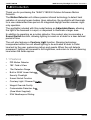
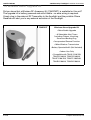
300W Security
Floodlight
754HF1/180/300
180° Outdoor Motion Sensor
®
Installation Instructions
Please leave these instructions at the installation site.
754HF1/180/300 300W Security Floodlight Installation Instructions
Contents
1.0 Introduction............................................................................................... 3
1.1 Features............................................................................................. 3
1.2 Wireless Alarm Upgrade Kit............................................................... 4
2.0 Installation Procedure.............................................................................. 5
2.1 Selecting a Location........................................................................... 5
2.2 Mounting the Unit............................................................................... 6
2.3 Electrical Connections....................................................................... 6
2.4 Halogen Lamp Replacement............................................................. 7
3.0 Commissioning Procedure...................................................................... 8
3.1 Walk Testing Procedure..................................................................... 8
3.2 Adjustment Knobs.............................................................................. 9
3.3 Setting up for Automatic Operation................................................. 10
3.4 Masking the Sensor Lens................................................................ 10
3.5 Special Functions..............................................................................11
4.0 Detection Range / Setting Controls....................................................... 12
5.0 Installation Diagram............................................................................... 13
6.0 Connection Diagram............................................................................... 14
7.0 Angle Adjustment................................................................................... 15
8.0 Lens Masking Diagram........................................................................... 15
9.0 Troubleshooting...................................................................................... 16
10.0 Technical Specifications........................................................................ 17
11.0 Warranty ................................................................................................ 18
12.0 Technical Support................................................................................... 18
13.0 Product Range........................................................................................ 19
2 of 20
© Clipsal Australia Pty Ltd
754HF1/180/300
300W Security Floodlight Installation Instructions
1.0 Introduction
Thank you for purchasing the 754HF1/180/300 Outdoor Infrascan Motion
Detector.
The Motion Detector unit utilises passive infrared technology to detect heat
radiation of moving human bodies. Upon detection, the spotlights will illuminate
for a user-determined time period. An integrated daylight sensor ensures nightonly operation.
The spotlights included with this model feature an Adjustable Beam, allowing
the light to be focussed in a spot, or dispersed to illuminate a larger area.
In addition to operating as a motion detector, this product also incorporates a
Sunset Switch function, allowing lighting to come on at dusk for a user defined
period of time.
The unit also features a Courtesy Light function. Dimming technology
incorporated within the unit allows lighting to be activated at dusk to a dim
level set by the user, welcoming visitors and guests. When the unit detects
movement, lighting will increase to full brightness, and return to the set dimming
level when the timer expires.
1.1 Features
•
PIR Motion Detector
•
180° Field of View
•
12m Detection Range
•
Built-in 300W Linear Halogen
Security Floodlight
•
Sunset Switch Function
•
Courtesy
tesy Light / Dimmer Function
•
Integral Override Facility
•
Customisable
le Detection Area
(Zone Mask Supplied)
•
IP44 Weatherproof Rating.
© Clipsal Australia Pty Ltd
3 of 20
754HF1/180/300
300W Security Floodlight Installation Instructions
1.2 Wireless Alarm Upgrade Kit
Did you know that a Wireless RF Accessory Kit (754RFKIT) is available for this unit?
The upgrade kit is battery powered and retro-fittable - no extra wiring is required.
Simply plug in the external RF Transmitter to the floodlight and the portable Chime
Receiver will alert you to any external activation of the floodlight.
754RFKIT
Wireless Alarm Upgrade Kit
• Retrofittable Upgrade
• 6 Selectable Alert Tones
Including Chimes, Knocking,
Sonar and Barking Dog
• Incorporated Snooze Function
• 100m Wireless Transmission
• Battery Operated 3xAA (Not Included)
• Indoor Use Only
• Compatible with 754HL1/140/150,
754HS1/140/60, 754HS2/140/60,
754HF1/180/150, 754HF1/180/300,
754HB1/180/60, 754HB2/180/60.
4 of 20
© Clipsal Australia Pty Ltd
754HF1/180/300 300W Security Floodlight Installation Instructions
2.0 Installation Procedure
Unit is for outdoor use only. Unit must be mounted on a non-flammable surface as a
fixed luminaire, and is not suitable for portable use. The unit can get very hot during
use. Ensure the unit has cooled before handling. Ensure adequate ventilation space
is allowed between the unit and any object above, in front or to either side of the unit.
Suggested space is 0.5m above, 0.3m to either side and 1.0m in front. Do not attempt
to install during wet weather conditions.
All electrical installations must be carried out by a Licensed Electrician.
2.1 Selecting a Location
1. The motion detector has a number of detection zones, at various vertical and
horizontal angles as shown (see Diagram A).
2. A moving human body needs to cross/enter one of these zones to activate the
sensor. The best all-round coverage is achieved with the unit mounted at the
optimum height of 2.5m.
3. Careful positioning of the sensor will be required to ensure optimum performance.
See Diagram B detailing detection range and direction.
4. The sensor is more sensitive to movement ACROSS its field of vision than to
movement directly TOWARDS (see Diagram B). Therefore position the unit so
that the sensor looks ACROSS the likely approach path.
5. Avoid positioning the sensor where there are any sources of heat in the detection
area (extractor fans, tumble dryer exhausts etc.) including any other light sources
such as other security lighting.
6. Reflective surfaces (i.e. pools of water or white painted walls) and overhanging
branches may cause false activation under extreme conditions.
7. During extreme weather conditions the motion sensor may exhibit unusual
behaviour. This does not indicate a fault with the sensor. Once normal weather
conditions return, the sensor will resume normal operation.
© Clipsal Australia Pty Ltd
5 of 20
754HF1/180/300 300W Security Floodlight Installation Instructions
2.2 Mounting the Unit
1. Remove the wall plate from the unit by inserting a terminal screwdriver into the
slot at the top (see Diagram D).
2. Mark the position of the fitting holes. Drill the holes. Insert wallplugs into the holes.
3. BEFORE SECURING THE WALLPLATE TO THE WALL PIERCE AND PASS THE
CABLE THROUGH THE GROMMET.
4. Attach the wall plate to the wall (see Diagram E).
2.3 Electrical Connections
1. Connect the cable to the terminal block on the wall plate as follows (see
Connection Diagram F):
NEUTRAL (Blue/Black)
N
EARTH (Green/Yellow)
ACTIVE/LIVE (Brown/Red)
L
2. Ensure that the connections are secure.
3. To reattach the unit to the wall plate line up the two pins at the top of the unit.
4. Push the unit against the wall plate and the unit will ‘click’ into place. Ensure that
the bottom clip is fully closed to ensure a weatherproof seal (see Diagram E).
NOTE:
It is recommended that a separate switch be installed inside the premises to switch
power to the unit ON and OFF. This allows the sensor to be easily switched off
when not required or for maintenance purposes (refer to ‘Manual Override Mode’
on page 11).
6 of 20
© Clipsal Australia Pty Ltd
754HF1/180/300 300W Security Floodlight Installation Instructions
2.4 Halogen Lamp Replacement - Caution
Replacement lamp type is 240V mains halogen 300W R7s cap floodlight lamp.
1. Isolate the mains supply.
2. Unfasten the clip on the top of the floodlight glass shield. Open the glass cover.
The cover is mounted on hinges and will swing open.
3. To remove existing lamp, depress then lift one end of the lamp to remove.
4. Install new lamp, making sure not to touch the lamp with bare hands. It is
suggested that the lamp is handled using a dry cloth. To install lamp, insert one
end first and depress gently until enough clearance is gained to seat the other
end in the socket. Rotate the lamp to ensure it is properly seated.
5. Re-fasten the clip to hold the floodlight glass shield in place.
WARNING:
•
Always handle quartz halogen lamps with a soft cloth. Do not touch the lamp with
your bare hand, as it will shorten the life of the lamp.
•
Do not touch the floodlight while it is in use or still hot. Switch the unit off, and
allow it to cool (about five minutes) before touching it.
•
In the event of the cover glass shattering, do not replace with normal household
glass. Do not operate without the glass shield in place. If the glass shield is
cracked or damaged, it must be replaced. If the glass is replaced, use only
tempered glass of equal thickness.
The Environment and You
Clipsal products are designed and manufactured to give many years of
trouble-free service. The materials used during manufacture have been selected to
improve their ability to be recycled when the product is no longer functional.Waste
electrical products should not be disposed of with household waste. Please recycle
where facilities exist. Check with your Local Authority or retailer for recycling advice.
Light Pollution and Considerate Lighting
Please be aware of the annoyance over-lighting an area can cause to your
immediate neighbours. Light pollution caused by incorrectly installing a unit or overlighting an area can be limited by carefully considering the location and position
of your unit before installation. The light spread on all halogen floodlights can be
reduced by angling the floodlight downwards on the mounting bracket. This will also
concentrate the light on your property and limit the potential inconvenience of the
light shining into your neighbours windows, etc.
© Clipsal Australia Pty Ltd
7 of 20
754HF1/180/300 300W Security Floodlight Installation Instructions
3.0 Commissioning Procedure
3.1 Walk Testing Procedure
1. The sensor will rotate from left to right. Adjust the sensor to point in the
desired direction (see Diagram A and H for the different sensor patterns and
lens masking).
2. Set the two adjustment knobs on the sides of the sensor (Diagram C) to the
following positions:
PIR TIMER
5 Seconds
Fully anti-clockwise
SUNSET TIMER
1 Hour
Fully anti-clockwise
LUX
Full Sunlight
Fully clockwise
DIM
0% (Off)
Fully anti-clockwise
3. The unit will now operate during daytime as well as at night, illuminating the lamp
for approximately five seconds each time. This allows testing to be carried out to
establish the best position for the sensor.
4. Switch on the mains power. The lamp will immediately illuminate as the unit goes
through its ‘warm-up’ period. After approximately one to two minutes the lamp will
extinguish. Try to remain outside the detection area during the warm-up period.
5. Walk across the detection area approximately five metres from the unit. As you
cross a detection ‘zone’ the lamp will illuminate. Now stand still until the lamp
extinguishes (this should take approximately five seconds).
6. Start moving again. As you cross each ‘zone’ the lamp will illuminate. Repeat the
above, walking at various distances and angles to the unit. This will help you to
establish the detection pattern.
7. The units sensor module can be adjusted horizontally from left to right. If the
detection area is too small for your requirements, try turning the sensor head.
This can increase the coverage distance or will reduce the range should a smaller
coverage area be required (see Diagram G to see how to adjust the floodlight
beam to suit).
8 of 20
© Clipsal Australia Pty Ltd
754HF1/180/300 300W Security Floodlight Installation Instructions
3.2 Adjustment Knobs
PIR TIMER
If the unit is set to AUTOMATIC MODE, the PIR TIMER setting
controls how long the unit remains illuminated after motion has
been detected (and after all motion has ceased). The minimum
time (fully anti-clockwise) is approximately 5 seconds, whilst
the maximum time (fully clockwise) is approximately 5 minutes.
Set the control to the desired setting between these limits.
SUNSET TIMER
If the unit is set in SUNSET SWITCH MODE, the SUNSET
TIMER setting controls how long the COURTESY LIGHT
remains illuminated after dusk. The Courtesy Light can be
set to a dim level (set by the DIM CONTROL) for a period
between 1 and 8 hours. Set the SUNSET TIMER CONTROL
to the desired setting between these limits.
1hr
8hrs
LUX CONTROL
The LUX setting controls the level of darkness required for the
unit to start operating. The setting is best achieved using the
following procedure: Set the LUX setting fully anti-clockwise.
The unit will now start operating at dusk. If you require the light
to activate earlier, wait until the ambient light level reaches
the level of darkness at which you wish the lamp to become
operative. Then SLOWLY rotate the control in a clockwise
direction until a point is reached where the lamp illuminates.
Leave the control at this set point.
DIM CONTROL
The DIM setting controls the COURTESY LIGHT in SUNSET
SWITCH MODE. The DIMMER is adjustable from 0% (OFF)
to 95% of the light output. When set, the DIMMER will activate
the light at dusk each evening. It will then stay illuminated at
this low level of courtesy lighting until the sensor is activated.
When movement is detected the lamp will go to full power for
the time period set by the PIR TIMER control. After the set
time has elapsed the light level will return to the dimmed light
level until the SUNSET TIMER period has elapsed.
© Clipsal Australia Pty Ltd
9 of 20
754HF1/180/300 300W Security Floodlight Installation Instructions
3.3 Setting up for Automatic Operation
1. When walk tests are complete, the unit can be switched to automatic operation.
2. The PIR TIMER setting controls how long the unit remains illuminated following
activation and after all motion ceases. The minimum time (fully anti-clockwise) is
approx. 5 seconds, whilst the maximum time (fully clockwise) is approximately five
minutes. Set the control to the desired setting between these limits.
3. The LUX control determines the level of darkness required for the unit to start
operating. The setting is best achieved by the procedure below:
• Set the LUX control knob fully anti-clockwise. The unit will now start operating
at dusk. If you require the light to activate earlier, wait until the ambient light
level reaches the level of darkness at which you wish the lamp to become
operative, SLOWLY rotate the control in a clockwise direction until a point is
reached where the lamp illuminates. Leave the control set at this point.
• At this position, the unit should become operative at approximately the same
level of darkness each evening. Observe the operation of the unit. If the unit is
starting to operate too early (i.e. when it is quite light), adjust the control slightly
anti-clockwise. If the unit starts to operate too late (i.e. dusk), adjust the control
slightly clockwise.
• Continue to adjust until the unit operates as desired.
3.4 Masking the Sensor Lens
1. The unit is supplied with a lens mask which allows the option to reduce the range
of the sensor.
2. The lens mask simply clicks over the sensor. When fitting ensure that your chosen
option is facing forwards. The engraved arrow indicates the front of the sensor.
3. Ensure that the arrow marked on the lens mask is lined up with the arrow on the
sensor. This will then give an indication of the front of the detection area (see
Diagram H).
4. Engraving on the lens mask indicates the effect on the detection range each
segment will have. These are 2m, 4m, 8m or 12m.
5. If no segments are removed then the sensor WILL NOT detect. The desired
range can be achieved by carefully removing the segments then repeating the
walk test after each segment has been removed until the desired detection area
is achieved.
10 of 20
© Clipsal Australia Pty Ltd
754HF1/180/300 300W Security Floodlight Installation Instructions
3.5 Special Functions
MANUAL OVERRIDE MODE
The light can be switched on for longer time periods by use of the MANUAL
OVERRIDE MODE. The light can be activated AT NIGHT by using the internal wall
switch / circuit breaker.
Switch the internal wall switch / circuit breaker OFF/ON within 2 seconds. The
unit will now illuminate continuously (OVERRIDE ON), and will remain ON until
MANUAL OVERRIDE MODE is cancelled, or until dawn the following day
(whichever comes first).
To cancel MANUAL OVERRIDE MODE and switch the unit back into AUTOMATIC
MODE, flick the internal wall switch / circuit breaker OFF/ON within 1 second. The
lamp will extinguish and the unit will return to normal automatic operation.
SUNSET SWITCH / COURTESY LIGHT MODE
This unit incorporates a SUNSET SWITCH MODE, designed to automatically activate
the COURTESY LIGHT at dusk. The unit will remain on at a convenient DIM setting
(1 - 95%) for a period of time set by the user (1 - 8 hours) each night.
To enable SUNSET SWITCH MODE, simply:
•
Set the SUNSET TIMER adjustment knob as required (1 - 8 hours).
•
Set the DIM CONTROL adjustment knob to any other setting other than 0% (fully
anti-clockwise).
At Sunset each evening, the COURTESY LIGHT will illuminate to a user defined low
level dimmer setting between 1 and 95% of maximum brightness, for the set time
between 1 and 8 hours.
Should movement be detected by the sensor when the COURTESY LIGHT is active,
the light will go to full brightness for the period set by the PIR TIMER, after which it
will drop back down to the low level DIM setting.
After the SUNSET TIMER period has elapsed, the lamp will extinguish and the unit
will resume normal operation, responding to movement as required.
Note that SUNSET SWITCH MODE will NOT reset to AUTOMATIC MODE at dawn, it
will repeat each night until reset by the user. To disable the SUNSET SWITCH MODE
simply set the DIM CONTROL to 0% (fully anti-clockwise).
© Clipsal Australia Pty Ltd
11 of 20
754HF1/180/300
300W Security Floodlight Installation Instructions
4.0 Detection Range / Setting Controls
A
B
TOP VIEW
Less
Sensitive
180°
SIDE VIEW
More
Sensitive
2.5m
SUNSET
TIMER
PIR
TIMER
C
12 of 20
12m
DIM
LUX
D
© Clipsal Australia Pty Ltd
754HF1/180/300
300W Security Floodlight Installation Instructions
5.0 Installation Diagram
E
© Clipsal Australia Pty Ltd
13 of 20
754HF1/180/300
300W Security Floodlight Installation Instructions
6.0 Connection Diagram
F
Wall Plate
Cable Entry
Neutral
Blue/Black
(N)
Earth
Green/Yellow
(E or
)
Active/Live
Brown/Red
(L)
Connect the mains cable to
N,E and L connections in the
terminal block
Match the three pins on the
unit to the wall plate.
14 of 20
© Clipsal Australia Pty Ltd
754HF1/180/300
300W Security Floodlight Installation Instructions
7.0 Angle Adjustment
G
The Floodlight can be adjusted to angle the beam to cover the required area.
20°
30°
70°
70°
CAUTION
IF THE PROTECTIVE GLASS SHIELD FOR THE LIGHT IS DAMAGED
OR CRACKED IT MUST BE REPLACED IMMEDIATELY.
8.0 Lens Masking Diagram
H
The arrows indicate the front
of the detection area in that
section of the sensor
Engraving indicates the
approx detection range of
each section
© Clipsal Australia Pty Ltd
15 of 20
754HF1/180/300 300W Security Floodlight Installation Instructions
9.0 Troubleshooting
PROBLEM
SOLUTION
Lamp stays ON all
the time at night.
The unit may be suffering from false activation. Cover the sensor lens
completely with a thick cloth. This will prevent the sensor from “seeing”
anything. If the unit now switches off after the set time duration and
does not re-activate, this indicates that the problem was caused by false
activation.
PIR keeps activating
for no reason / at
random.
The problem may be solved by slightly adjusting the direction/ angle of
the sensor head (see previous section).
You may not be allowing the unit time to complete its warm-up period.
Stand well out of the detection range and wait (the warm-up period
should never exceed five minutes).
Occasionally, winds may activate the sensor.
Sometimes passages between buildings etc. can cause a
‘wind tunnel’ effect.
Ensure the unit is not positioned so as to allow detection of
cars / people using public thoroughfares adjacent to your property.
PIR sensor will not
operate at all.
Check that the power is switched ON at the circuit
breaker / internal wall switch.
Turn OFF the power to the unit and check the wiring connections as per
the diagram (see previous section F). Ensure no connections are loose.
Check the lamp. If the lamp has failed, replace. Ensure that the lamp is
seated correctly in the lampholder.
The PIR sensor will
not operate at night.
The level of ambient light in the area may be too bright to allow operation
at the current DUSK setting. During the hours of darkness, adjust the
DUSK control slowly clockwise until the lamp illuminates. Refer to
previous section for more details.
Unit activates
during the daytime.
The level of ambient light in the area may be too dark for the current
DUSK setting. During daylight, adjust the DUSK control slightly anticlockwise. When the lamp extinguishes, enter the detection area. If
the PIR still activates, the setting is still too high. Repeat the above
procedure until the PIR does not activate when you enter the detection
area. Refer to previous section for more details.
PIR coverage is
poor / sporadic.
Unit may be poorly located. See previous section - ‘Selecting The
Location’ and re-locate the unit.
Detection range
varies from day
to day.
PIR sensors are influenced by climatic conditions. The colder the
ambient temperature, the more effective the sensor will be. You may
need to make seasonal adjustments to the sensor head position to
ensure trouble-free operation all year round.
16 of 20
© Clipsal Australia Pty Ltd
754HF1/180/300 300W Security Floodlight Installation Instructions
10.0 Technical Specifications
Operating Voltage
240V~ 50Hz a.c.
Maximum Switchable Load (Watts)
300W
Lamp Type
240V~ Linear Tungsten Halogen 300W max
R7s cap
Conductors Required
3 Wire
Neutral Required
YES
Rated Detection Range
12 metres
Field of View
180°, User Adjustable
Timer Delay Range
5 Seconds to 5 Minutes, User Adjustable
Sunset Switch Time Delay Range
1 Hour to 8 Hours, User Adjustable
Light Level Inhibit Threshold
1 Lux to 2000 Lux, User Adjustable
Courtesy Dimming Control Range
0 - 95%, User Adjustable
Warm up Time
1 - 2 Minutes
Mounting Surface
Wall Mount (Flat Surface Required)
Optimal Mounting Height
2.5 Metres
Environmental Protection
IP44 (weatherproof)
Specifications Typical @ 240Va.c. 25°C
No User Servicable Parts Inside
This Product is Recommended for OUTDOOR USE ONLY
© Clipsal Australia Pty Ltd
17 of 20
754HF1/180/300 300W Security Floodlight Installation Instructions
11.0 Warranty
1. The benefits conferred herein are in addition to, and in no way shall be deemed to
derogate; either expressly or by implication, any or all other rights and remedies in
respect to the Clipsal Product, which the consumer has under the Commonwealth
Trade Practices Act or any other similar State or Territory Laws.
2. The warrantor is Clipsal Australia Pty Ltd of 33-37 Port Wakefield Road, Gepps
Cross, South Australia 5094. Telephone (08) 8161 0511. With registered offices in
all Australian States.
3. This Clipsal Product is guaranteed against faulty workmanship and materials for
a period of two (2) years from the date of installation. Warranty excludes any user
replaceable parts, in particular lamps and glass panels. No liability is accepted in
relation to discolouration of plastic or painted parts.
4. Clipsal Australia Pty Ltd reserves the right, at its discretion, to either repair free of
parts and labour charges, replace or offer refund in respect to any article found to
be faulty due to materials, parts or workmanship.
5. This warranty is expressly subject to the Clipsal Product being installed, wired,
tested, operated and used in accordance with the manufacturer’s instructions.
6. All costs of a claim shall be met by Clipsal Australia Pty Ltd, however should the
product that is the subject of the claim be found to be in good working order all
such costs shall be met by the claimant.
7. When making a claim the consumer shall forward the Clipsal Product to the
nearest office of Clipsal Australia Pty Ltd with adequate particulars of the defect
within 28 days of the fault occurring. The product should be returned securely
packed, complete with details of the date and place of purchase, description of
load, and circumstances of malfunction.
12.0 Technical Support
For all technical enquiries and assistance please contact our
National Customer Service Enquiries Hotline
Tel 1300 2025 25
Fax 1300 2025 56
(Call cost 25c, number valid within Australia only)
18 of 20
© Clipsal Australia Pty Ltd
754HF1/180/300 300W Security Floodlight Installation Instructions
13.0 Notes
____________________________________________________________________
____________________________________________________________________
____________________________________________________________________
____________________________________________________________________
____________________________________________________________________
____________________________________________________________________
____________________________________________________________________
____________________________________________________________________
____________________________________________________________________
____________________________________________________________________
____________________________________________________________________
____________________________________________________________________
____________________________________________________________________
____________________________________________________________________
____________________________________________________________________
____________________________________________________________________
____________________________________________________________________
____________________________________________________________________
____________________________________________________________________
____________________________________________________________________
____________________________________________________________________
____________________________________________________________________
____________________________________________________________________
____________________________________________________________________
© Clipsal Australia Pty Ltd
19 of 20
754HF1/180/300
300W Security Floodlight Installation Instructions
14.0 Product Range
The following products are also available in the 754 Series:
754HL1/140/150
150W Security Floodlight
140° Passive Infrared Outdoor Motion Detector
Complete with 150W R7s Linear Halogen Floodlight
754HS1/140/60
60W Security Spotlight
140° Passive Infrared Outdoor Motion Detector
Complete with Single 60W G9 High Efficiency Halogen Spotlight
754HS2/140/60
60W Security Twinspot
140° Passive Infrared Outdoor Motion Detector
Complete with Twin 60W G9 High Efficiency Halogen Spotlights
754HF1/180/150
150W Security Floodlight
180° Passive Infrared Outdoor Motion Detector
Complete with 150W R7s Linear Halogen Floodlight
754HF1/180/300
300W Security Floodlight
180° Passive Infrared Outdoor Motion Detector
Complete with 300W R7s Linear Halogen Floodlight
754HB1/180/60
60W Security Spotlight
180° Passive Infrared Outdoor Motion Detector
Complete with Single 60W G9 High Efficiency Halogen Spotlight
754HB2/180/60
60W Security Twinspot
180° Passive Infrared Outdoor Motion Detector
Complete with Twin 60W G9 High Efficiency Halogen Spotlights
Clipsal Australia Pty Ltd
clipsal.com
A member of Schneider Electric
Contact us: clipsal.com/feedback
National Customer Care Enquiries:
Tel 1300 2025 25
Fax 1300 2025 56
Clipsal Australia Pty Ltd reserves the right to change specifications, modify designs and discontinue
items without incurring obligation and whilst every effort is made to ensure that descriptions,
specifications and other information in this catalogue are correct, no warranty is given in respect thereof
and the company shall not be liable for any error therein.
© Clipsal Australia Pty Ltd. The identified trademarks and copyrights are the property of
Clipsal Australia Pty Ltd unless otherwise noted.
F2106/03
CLIPCOM 21420 May 2010