1
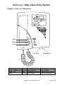
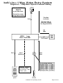
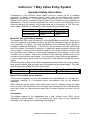
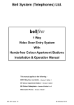
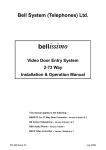
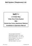
Bell System (Telephones) Ltd.
bellissimo
Video Door Entry System
1 Way
Installation & Operation Manual
PD-097 Issue 2
TABLE OF CONTENTS
INTRODUCTION ........................................................................................................ 1
DESCRIPTION ............................................................................................................ 1
MAIN FEATURES ........................................................................................................ 1
DIAGRAM 1: BELLISSIMO VIDEOPHONE .......................................................................... 2
BASIC SYSTEM OPERATION................................................................................... 3
Call sequence ...................................................................................................... 3
Silent viewing....................................................................................................... 3
Auto Display......................................................................................................... 3
Call Mute.............................................................................................................. 3
Door Status Indication.......................................................................................... 3
Call Privacy.......................................................................................................... 4
User Activation (CCTV Mode).............................................................................. 4
Second camera.................................................................................................... 4
Extension Videophones ....................................................................................... 4
Lock Type and Operation..................................................................................... 4
Exit Button and Fire Switch.................................................................................. 4
Trades Facility ..................................................................................................... 4
DDA Functionality ................................................................................................ 5
Multiple Entrances ............................................................................................... 5
DESIGN CONSIDERATIONS..................................................................................... 6
EQUIPMENT LIST ........................................................................................................ 6
OPTIONS ................................................................................................................... 6
Entrance Panel .................................................................................................... 6
Door Controller .................................................................................................... 6
POWER SUPPLY REQUIREMENTS................................................................................. 7
The system is powered by 12V PSU’s only: - ...................................................... 7
CABLE SPECIFICATION. .............................................................................................. 7
CAT5 cable .......................................................................................................... 8
Cable Distances (refer to diagrams A and C) ...................................................... 8
INSTALLATION & COMMISSIONING ....................................................................... 9
WIRING..................................................................................................................... 10
Entrance Panel .................................................................................................. 10
Videophone........................................................................................................ 10
Electric Door Release ........................................................................................ 10
Exit Button Input ................................................................................................ 10
Door Open Switch.............................................................................................. 10
BSD1 DOOR CONTROLLER SETTINGS ................................................................ 11
BSD1 DOOR CONTROLLER SWITCH SETTINGS .......................................................... 11
Talking Time/Videophone Active DIP SW1 (1-4) .............................................. 11
Ringing Time/Call Time and Ring Effect DIP SW1 (5-8) ................................... 11
Lock Operate Time Dip SW2 (1-3).................................................................... 12
Individual Functions DIP SW2 (4-8).................................................................. 12
Camera Numbering DIP SW3 (1-8) .................................................................. 13
Installation and Operating Manual
Page ii
View Activated by User ...................................................................................... 13
‘Global View’ at Multiple Entrances.................................................................... 13
BSD1 DOOR CONTROLLER JUMPER SETTINGS .......................................................... 14
BS VIDEOPHONE SWITCH SETTINGS .................................................................. 15
Mute Time Setting SW1 (1-4) ........................................................................... 15
Individual Functions DIP SW1 (5-8).................................................................. 15
DIAGRAM A – 1 WAY BASIC SYSTEM OVERVIEW CABLING............................. 16
DIAGRAM B – 1 WAY BASIC SYSTEM WIRING DETAIL ...................................... 17
DIAGRAM C – 1 WAY MULTIPLE ENTRANCE OVERVIEW CABLING................. 18
DIAGRAM D – 1 WAY MULTIPLE ENTRANCE WIRING DETAIL .......................... 19
DIAGRAM E – VIDEOPHONE AND EXTENSION WIRING ..................................... 20
DIAGRAM F – VIDEOPHONE LOCAL POWER WIRING........................................ 21
TROUBLESHOOTING.............................................................................................. 22
SPECIFICATIONS.................................................................................................... 24
IMPORTANT SAFETY INFORMATION ................................................................... 25
Model 840 PSU (with battery standby)............................................................... 25
Model PS4 and 340C Power Supplies............................................................... 25
Videophone........................................................................................................ 25
Installation and Operating Manual
Page iii
bellissimo 1 Way Video Entry System
Introduction
Description
A bellissimo video door entry system consists of a door panel, positioned at the
entrance of a building, a video telephone (videophone), placed inside of the building
for the convenience of the occupant and a power supply and controller which are
usually located inside an electrical cupboard. The door panel comprises of a twoway speech unit, a camera and a push button – which must be depressed by a visitor
to initiate a call. The videophone, which rings in response, allows a two-way
conversation via a handset whilst the caller can be observed through the integral
display. The operator can selectively allow visitors access to the building by pressing
a button on the videophone and so electrically releasing the door.
The bellissimo 1-way Video Door Entry System is suitable for any building requiring a
single push button at the entrance, such as houses, individual flats and offices. For
multi-way systems please refer to “bellissimo 2-72-way Video Entry System” manual.
The bellissimo “1-way” system is supplied with a dedicated door controller, which has
been specifically optimised for “1-way” systems, ensuring simple installation. This
basic system can support up to 3 extension videophones (more with additional
PSU’s), whilst multiple entrances can be supported with the addition of one panel
and one controller for each door.
Main Features
●
●
●
●
●
●
●
●
●
●
●
●
●
●
●
●
●
CAT5 cable throughout; no co-ax required!
4” Flat screen display.
High resolution CCD camera with infrared lamps.
12V d.c. Operation
High quality full-duplex speech amplifier.
Automatic picture display while ringing.
Operator activated picture (CCTV mode)
Ringer mute function.
Fail safe or Fail secure lock releases and Magnetic locks.
Lock release timer.
Tradesman facility (optional).
Facility for exit button and/or fire switch.
Door ‘open’ indication.
Second camera option.
DDA panel options.
Up to 3 Extension videophones.
Multi-entrances supported.
Installation and Operating Manual
Page 1 of 25
bellissimo 1 Way Video Entry System
Diagram 1: bellissimo Videophone
View
Mute
Lock
Contrast
Button
View / Camera select
Mute on/off
Lock
Lamp
Amber
Red
Green
Steady
Call in progress
Videophone is muted
Door is open
Installation and Operating Manual
Brightness
Flashing
There is a call
Videophone is Off-Hook
Press to release lock
Page 2 of 25
bellissimo 1 Way Video Entry System
Basic System Operation
Call sequence
When the push button is pressed at the entrance panel it causes the videophone to
ring and the amber call lamp to flash. The videophone will continue to ring for up to
30 seconds or until the resident responds by picking up the handset. At this time the
resident can freely converse with the visitor whose image is now displayed on the
videophone; at the same time the green door lamp will flash to highlight the lock
button.
The call may be terminated by replacing the handset or more usually by pressing the
lock button to allow the visitor access through the entrance; the speech and picture
will persist for a further 3 seconds while the door is being released.
Silent viewing
When the videophone is ringing the resident can press the view button first instead of
lifting up the handset; this will stop the videophone ringing and enable them to view
the visitor for up to 60 seconds or until they press the lock button to release the door.
Silent viewing can be ‘normalised’ at any time by picking up the handset and
conversing with the visitor as described above.
Auto Display
When ‘Auto Display’ mode is selected the picture will come on while the videophone
is ringing, otherwise the picture will only come on when the call is answered. Auto
Display mode is usually pre-selected at installation and generally only one
videophone will be set in this mode (see ‘Extension Videophones’ below).
Call Mute
The resident can mute the ringing sound in the videophone when they do not wish to
be disturbed. Call mute is activated by pressing the mute button on the videophone,
which then illuminates in red as a reminder. The handset must be on the hook for this
to work. Pressing the mute button a second time will disengage the mute. During
installation it is possible to set a time limit for the mute function in various values from
2 minutes up to 10 hours. When this time period has elapsed the mute will
automatically disengage. (See ‘mute timer’, page 15).
The mute feature can be set during installation to one of two modes (or disabled
altogether): Ringer Mute only stops the audible ring, but the amber light will still flash and
all other functions work normally. Ringer mute will continue for the preset time
even if a call is answered. Pressing the mute button again while the
videophone is idle will cancel mute.
Full Mute prevents the videophone both from ringing or flashing the amber
call lamp. Pressing the mute button again or lifting the handset will cancel full
mute.
Door Status Indication
The green door lamp on the videophone will illuminate to warn the resident that a
door has been left open following a call. This feature requires a door monitor contact
to be fitted.
Installation and Operating Manual
Page 3 of 25
bellissimo 1 Way Video Entry System
Call Privacy
Once a call has been answered by one videophone no other videophones may join
in, view or listen to the call. If another videophones handset is picked up the
videophone will not activate; pressing the view button on another videophone will be
ignored.
User Activation (CCTV Mode)
While the system is idle, pressing the view button will activate the system and display
the picture at the entrance panel. Once activated, lifting the handset will enable
speech at the entrance and the lock button may now be used to release the door or
the user can hang-up. The picture will switch off after the preset talk-time.
Second camera
The Door Controller has the capability of driving a second ‘third party’ ‘CCTV’
camera, which is located nearby, and offering a different viewpoint. Pressing the
‘View/Camera’ button will alternate the view between the primary and secondary
camera (if enabled).
Extension Videophones
Additional videophones may be added to the basic system. The number of
extensions is limited only by power supply considerations. All videophones will ring
when called however typically only the Master unit will display a picture while ringing.
Once the master or extension videophone is ‘picked-up’ the picture will display on
that unit alone.
It should be noted that when the Master unit is left off-hook, extension videophones
will not ring; the red light will flash on the Master as a warning of this condition.
Lock Type and Operation
The door controller supports both fail-secure and fail-safe locks including magnetic
locks of up to 1A rating. The lock output is provided by relay contacts, which in the
event of power failure are open.
On pressing the lock button the lock timer will start and the door will unlock. The
picture (and speech if active) will persist for the first 3 seconds of lock operation. For
Lock Time settings see page 12.
Exit Button and Fire Switch
An input is provided for an exit button, which can be installed on the inside of the
door and allow residents to exit freely. Momentary operation of this button will
operate the lock release for the programmed lock time. A Fire switch or other
override device may use the same input to hold the door open indefinitely.
Trades Facility
Use of a time clock in conjunction with a trades button will allow free access during
the programmed time.
Installation and Operating Manual
Page 4 of 25
bellissimo 1 Way Video Entry System
DDA Functionality
A range of options exists for entrance panels, which meet the requirements of the
Disability Discrimination Act (DDA) including Braille buttons and LED indicators.
Contact your sales representative for further details.
Multiple Entrances
The bellissimo One-way System allows multiple entrances to be catered for by the
addition of one door controller and one entrance panel for each entrance and in
some instances additional power supplies. In a multiple entrance system an optional
feature allows the resident to view the cameras at all the entrances with successive
presses of the ‘camera select’ button.
For details of this camera feature and user activation see the setting for ‘Camera
Numbering’ on page13.
Installation and Operating Manual
Page 5 of 25
bellissimo 1 Way Video Entry System
Design Considerations
Equipment List
A BS1 one-way bellissimo Video Kit comprises the following: Model No
1 x BS
1 x BSP1
1 x BSD1
1 x PS4
1 x 203
Description
Videophone
Standard or panel with a model 61 speech unit and Cam BV.
Door controller.
4A 12V power supply.
Fail-secure lock release
For a Vandal Resistant Panel order a BS1/VR Kit
Options
For a 1 way system the following options are available: ● Extensions Model BS Videophone(s)
● Additional entrances, each comprising a BSD1 controller and BSP1 panel.
(See also PSU requirements)
● Alternate lock releases, fail-safe and fail-secure
● Trades facility; specify BS1+TRBS; includes a model TS2000-BST time-clock
● Exit button.
● Battery back up PSU, Model 840 (12V 4A)
● DDA panels (Contact sales for further information)
Entrance Panel
Careful consideration should be given to the location of the entrance panel to ensure
the best possible lighting conditions for the camera. In general strong back lighting of
the subject (by the sun and sky) should be avoided, as the contrast between
foreground and background may be too great for the camera. The field of view
should contain as little of the sky as possible, particularly if south facing. If a backlit
situation is unavoidable, additional lighting may be necessary to illuminate the caller
and avoid a dark outline image (silhouette).
Door Controller
The door controller and PSU should be wall-mounted in a convenient cupboard or
other protected environment with available mains power. Cable length to the
entrance should be less than 50m. The door controller for the second and
subsequent entrances may be situated in the same location, or to meet the 50m
requirement may be situated in another location. Power supplies may be shared
between door controllers placed in the same location, but controllers in separate
locations should be separately powered.
Installation and Operating Manual
Page 6 of 25
bellissimo 1 Way Video Entry System
Power Supply Requirements
The system is powered by 12V PSU’s only: PS4 12V, 4A
340C 12V, 1.5A Optional for extensions
Note 1. The 28V refered to on the videophone, door controller and wiring diagrams
is internally generated in the controller. DO NOT use any PSU other than 12V or
damage may occur.
Note 2. The PS4 power Supply has been specifically designed to operate with the
high-surge requirements of the system. Bell Systems are unable to guarantee
functionality or provide support for systems which use third party power supplies.
Exact power supply requirements depend upon many factors. The number of power
supplies included within a standard ‘kit’ assumes that all controllers are installed in
one location and that there are no extensions.
The following table is a guide: (Please contact Technical support for other variations)
System
Power Supplies
BS1 Kit
1 x PS4
BS1 & 3 Extension videophones 1 x PS4
(No auto display)
BS1 & 3 Extension videophones 1 x PS4
(All with auto display)
3 x 340C
2 Door one-way system
1 x PS4
3 Door one-way system
2 x PS4
Comments
Supplied in kit
Only the Master videophone
will have auto display
A 340C will supply each of
the extension videophones
Both BSD1 door controllers
must be in the same location
2 BSD1 door controllers per
PS4 power supply
Assumes maximum Lock Release current of 1A
Cable Specification.
All system wiring must be carried out using CAT5 signal cable and where necessary
1mm² (or greater) power cable as tabulated below. CAT5 cable has a known
performance for the transmission of video signals, whilst telephone or alarm cables
are not suitable. Bell Systems will be unable to offer any warranty or support for
systems installed using incorrect cables.
Installation and Operating Manual
Page 7 of 25
bellissimo 1 Way Video Entry System
CAT5 cable
CAT5 is our short reference for EIA standard UTP Category 5 Unshielded Twisted
Pair data cable. This is a standard solid core twisted pair cable having 4 pairs (8–
cores) and no shield. The cores are in pairs where Blue and ‘Blue with a White stripe’
are twisted together as the first pair. The other three pairs are similar with main
colours Orange, Green and Brown.
· Also available and acceptable are:
UTP Category 5e (CAT5e)
UTP Category 6 (CAT6)
UTP Category 6e (CAT6e)
The exact cable can be chosen from the above on cost and availability grounds.
·
·
STP (Shielded Twisted Pair) cables are not recommended.
UTP patch cables are not recommended.
NOTE: CAT5 cable is easily identifiable as it has its specification printed on the
sheath
Cable Distances (refer to diagrams A and C)
Door Controller to Videophone
System
Distance Cable
Comments
System with single
< 75m
1 x CAT5
videophone
< 300m
1 x CAT5
2 x 1mm2
System with 3 Extension
< 50m
1 x CAT5
Only Master videophone has
videophones:
‘Auto display’
Single PS4 power supply
System with 3 Extension
< 300m
1 x CAT5
All videophones have Auto
2
videophones:
display
<5m
2 x 1mm
Extensions each 1 x 340C
each
PSU
340C
Panel to Door Controller
All Systems, each entrance <50m
1 x CAT5
Basic Features only
Lock Release up to 1A
<10m
¼ x CAT5
<50m
2 x 1mm2
Option: Exit button
<50m
¼ x CAT5
Option: Trades button
<50m
¼ x CAT5
Requires a Time-clock
Option: Door Monitor Switch <50m
¼ x CAT5
Power Supply to Door Controller
All Systems, each PS4 to
<3m
2 x 1mm2
BSD1
<5m
2 x 1.5mm2
NB. A CAT5 cable has 4-pairs (8 cores)
For larger cable distances please contact manufacturer.
Installation and Operating Manual
Page 8 of 25
bellissimo 1 Way Video Entry System
Installation & Commissioning
The following checklist is a reminder of what is required. Refer to the relevant pages
for further details.
●
●
●
●
●
●
Review the section headed ‘Important Safety Information’.
Ensure that ‘Design Considerations’ have been studied and understood.
Confirm that CAT5 cable has been specified.
Install the system according to instructions in this section.
Check/set the Door Controller Dipswitch and Jumper settings.
Check/set each Videophone Dipswitch settings.
Installation and Operating Manual
Page 9 of 25
bellissimo 1 Way Video Entry System
Wiring
Refer to Diagram B for single entrance systems and Diagram D for multi-entrances.
All wiring is carried out using a mixture of CAT5 for the signal wiring and 1mm² (or
greater) cores for the power wiring; refer to Page 8 for further details. It is strongly
recommended that a consistent colour code be used throughout such as that
indicated on the connection diagram. Certain signals must be interconnected using a
twisted pair from the CAT5 cable. These are clearly marked on the connection
diagram and should be strictly observed.
Entrance Panel
The panel should be mounted at an optimum height of 1.6 m, measured between the
ground and the centre of the camera window. With flush mounting panels it is
advisable to apply mastic to the top edge of the panel to prevent water ingress
behind the panel. On construction sites the panel must be protected from corrosive
substances such as ‘brick acid’. The panel should be cleaned only with a damp cloth
containing dilute detergent.
Videophone
The Videophone is designed to be wall mounted onto plasterboard or other masonry
at an optimum height of 1.6m. It should be fixed with three No 8 screws (not
supplied). Use the template included with the videophone to mark out the drilling
positions, and drill the three holes and insert the appropriate wall plugs. If the cable is
to be feed from the wall cavity then make a hole for this at the same time. Fit the top
two screws but do not fully tighten. Now remove the top cover of the videophone,
which is secured by clips at both sides. If top or bottom cable entries are required,
careful remove the appropriate cutout with side snips taking care not to damage any
internal components. Hang the videophone on the two screws already fitted allowing
the cable (if present) to feed through and the third screw to be inserted at the bottom.
Tighten all three screws. Before replacing the Front Cover remove the protective film
from the display lens and also check that the DipSwitch settings are correct or
change as necessary (see Page 15).
Electric Door Release
Both fail-secure and fail-safe lock releases (inc. magnetic locks) use the same
terminals. To set the lock type, refer to the “Door Controller Switch” settings. When
installing lock releases please allow a little movement on the door, as operation will
be impaired if fitted too tight.
NB. Magnetic locks (maglocks) must be fitted with a suppressor at the lock
terminals. Some manufacturers fit an acceptable internal suppressor.
Exit Button Input
This input is for a normally open push button. ‘Exit +’ is the input and ‘Exit –’ is
internally connected to 0V.
Door Open Switch
This switch can have closed contacts when the door is open or open contacts when
the door is open. Dip SW2-5 sets the choice. The default of ‘contacts closed when
door open’ must be selected when this feature is not required.
Installation and Operating Manual
Page 10 of 25
bellissimo 1 Way Video Entry System
BSD1 Door Controller Settings
BSD1 Door Controller Switch Settings
Talking Time/Videophone Active DIP SW1 (1-4)
Talk Time
15s
20s
30s
45s
60s
75s
90s
120s
150s
180s
60s
60s*
SW1 SW2 SW3
(ASDFGHJK)
(ASDFGHJK)
(QWERGHJK)
4 3 2 1
On On On On
On On On Off
On On Off On
On On Off Off
On Off On On
On Off On Off
On Off Off On
On Off Off Off
Off On On On
Off On On Off
Other settings
Off Off Off Off
OFF ↔ ON
* Default setting
Ringing Time/Call Time and Ring Effect DIP SW1 (5-8)
7
On
On
On
On
Off
Off
Off
Off
On
On
On
On
Off
Off
Off
Off
6
On
On
Off
Off
On
On
Off
Off
On
On
Off
Off
On
On
Off
Off
5
On
Off
On
Off
On
Off
On
Off
On
Off
On
Off
On
Off
On
Off
Call Time
5s
8s
10s
15s
20s
30s
40s
45s
50s
60s
30s¹
30s¹
30s¹
30s¹
30s¹
30s*
Ring Cadence or Sound Effect
1 in 3 – 1 ring every 3 seconds
1 in 3 – 1 ring every 3 seconds
1 in 3 – 1 ring every 3 seconds
1 in 3 – 1 ring every 3 seconds
1 in 3 – 1 ring every 3 seconds
1 in 3 – 1 ring every 3 seconds
1 in 3 – 1 ring every 3 seconds
1 in 3 – 1 ring every 3 seconds
1 in 3 – 1 ring every 3 seconds
1 in 3 – 1 ring every 3 seconds
1 in 3 (Reserved For future use)
1 in 3 (Reserved For future use)
2 in 15 – 2 rings, 15S silence, repeat
1 in 15 – 1 ring, 15S silence, repeat
1 in 5 – 1 ring every 5 seconds
1 in 3* – 1 ring every 3 seconds
SW1 SW2 SW3
(ASDFGHJK)
(ASDFGHJK)
(ASDFTYUI)
8
On
On
On
On
On
On
On
On
Off
Off
Off
Off
Off
Off
Off
Off
OFF ↔ ON
* Default setting
¹ BS videophones build 3 and above; Build 1&2 videophones: 1 ring every 2 seconds.
Installation and Operating Manual
Page 11 of 25
bellissimo 1 Way Video Entry System
Lock Operate Time Dip SW2 (1-3)
2
On
On
Off
Off
On
On
Off
Off
1
On
Off
On
Off
On
Off
On
Off
Lock Time
3s*
4s
5s
6s
8s
10s
15s
20s
SW1 SW2 SW3
(ASDFGHJK)
(123FGHJK)
(ASDFGHJK)
3
On
On
On
On
Off
Off
Off
Off
OFF ↔ ON
* Default setting
Individual Functions DIP SW2 (4-8)
SW1 SW2 SW3
(ASDFGHJK)
(ASDRTYUI)
(ASDFGHJK)
OFF ↔ ON
SW2-4 Lock Type
*Off Fail secure lock
Lock behaviour during power failure
Requires alternate mechanical means, key or
thumb-turn to open on power failure
On
Fail safe lock
Lock opens on power failure
SW2-5 Door Status Switch Monitors doors left open
From
*Off Contacts Open when The default allows for no switch fitted
build 2
Door is Closed
onwards
On
Contacts Closed when Standard normally closed switch
Door is Closed
SW2-6 Camera 2
How many cameras at this door
From
build 2
*Off Camera 1 only
Default – single camera per door
onwards
On
Enable Camera 2
Second camera at the door
SW2-7 View Function
Camera action when view button pressed
*Off Local View
View button only selects the camera(s) at this From
build 3
door
On
Global View
View button sequentially selects all cameras onwards
(See DIP SW3 below) at doors with this switch set
SW2-8 View User Activated View button pressed when system is idle
*Off Disabled
View button only works when called from the From
build 3
panel
onwards
On
Enabled
User can activate the system and look
See DIP SW3 below to see anyone near the door(s)
* Default setting
Installation and Operating Manual
Page 12 of 25
bellissimo 1 Way Video Entry System
Camera Numbering DIP SW3 (1-8)
SW1 SW2 SW3
(QWERTYUI)
(ASDFGHJK)
(ASDFGHJK)
Camera 1 at this door
Last Camera
4 3 2 1 Number
8 7 6 5 Number
On On On On 1
On On On On 1
On On On Off 2
On On On Off 2
On On Off On 3
agama On On Off On 3
On On Off Off 4
On On Off Off 4
On Off On On 5
On Off On On 5
On Off On Off 6
On Off On Off 6
On Off Off On 7
On Off Off On 7
On Off Off Off 8
On Off Off Off 8
Off On On On 9
Off On On On 9
Off On On Off 10
Off On On Off 10
Off On Off On 11
Off On Off On 11
Off On Off Off 12
Off On Off Off 12
Off Off On On 13
Off Off On On 13
Off Off On Off 14
Off Off On Off 14
Off Off Off On 15
Off Off Off On 15
Off Off Off Off *16
Off Off Off Off *16
OFF ↔ ON
* Default setting
View Activated by User
If ‘view activated by user’ is enabled, then one door controller must have SW3 1-4 set
as camera 1. Camera 1 at this entrance will then be the first camera to be viewed.
‘Global View’ at Multiple Entrances
If ‘Global View’ is enabled, successive presses of the view button will enable all
entrance to be viewed in turn, including any second cameras, if enabled.
Setting up the door controllers to enable ‘Global View’ requires careful setting of the
switches. Not all entrances have to participate in ‘Global View’, and these entrances
should remain set to ‘Local View’.
The participating entrances must each be designated with a unique address 1, 2, 3,
…etc in the required viewing sequence. NB the sequence must start with 1; the
maximum is 16. If Camera 2 is enabled on any entrance then it will adopt the
entrance address setting plus 1; the next entrance must skip that address.
Each controller must also record the last camera number in the sequence – this will
be the same setting for all entrances.
Below are a couple of examples and a blank table for your use.
Installation and Operating Manual
Page 13 of 25
bellissimo 1 Way Video Entry System
Example 1: Entrance Cameras at
number
this entrance
1
2
2
1
3
2
Example 2: Entrance Cameras at
this entrance
1
1
2
2
First Camera
DIP SW3 (1-4)
1
3
4
Last Camera
DIP SW3 (5-8)
5
5
5
First Camera
DIP SW3 (1-4)
1
2
Last Camera
DIP SW3 (5-8)
3
3
Customer’s setup: Entrance Cameras at
First Camera Last Camera
this entrance DIP SW3 (1-4) DIP SW3 (5-8)
1
2
3
4
5
6
7
8
9
10
11
12
BSD1 Door Controller Jumper Settings
The “Video Gain” jumper on door controllers should always be set to “Low” unless
directed by Bell System Technical. This jumper is only required on some systems
with very long camera to videophone cable runs well in excess of 150m. Use of this
jumper with short runs will cause picture problems.
Installation and Operating Manual
Page 14 of 25
bellissimo 1 Way Video Entry System
BS Videophone Switch Settings
Mute Time Setting SW1 (1-4)
3
On
On
On
On
Off
Off
Off
Off
On
On
On
On
Off
Off
Off
Off
2
On
On
Off
Off
On
On
Off
Off
On
On
Off
Off
On
On
Off
Off
1
On
Off
On
Off
On
Off
On
Off
On
Off
On
Off
On
Off
On
Off
Mute Time
Disabled¹
2 minutes
5 minutes
10 minutes
15 minutes
20 minutes
30 minutes
45 minutes
1 hour
2 hours
4 hours
5 hours
6 hours
8 hours
10 hours
*Indefinite²
SW1
(QWEFGHJK)
4
On
On
On
On
On
On
On
On
Off
Off
Off
Off
Off
Off
Off
Off
OFF ↔ ON
* Default setting
¹Disabled means pressing the mute button has no effect.
²Indefinite; the mute is cancelled by pressing the button again.
(ASDRTYU8)
Individual Functions DIP SW1 (5-8)
SW1
OFF ↔ ON
SW1-5 Master / Slave
*Off
Master videophone
On
Slave videophone /
Extension
SW1-6 Auto Display on Ring
*Off
Display During Ring
On
No Display During Ring
SW1-7 Mute Function
*Off
Ringer Mute Only
On
Disable Videophone
SW1-8 Video Terminator
Off
No Termination
*On
Terminate – Last
Videophone
Extension videophones are slaves
Single videophone or one in daisy-chain is master8
Extra videophones per call or flat
Caller visible while ringing
Yes
No
Action of mute button
No sound, Visible ring – view flashes, picture if enabled
Same as leaving off hook but steady not flashing button
Prevents cable reflections
Daisy-chained videophones not at end of cable
Must be on in videophone at end of cable
* Default setting
Installation and Operating Manual
Page 15 of 25
bell issim o 1 W ay V ideo Entry S ystem
Diagram A – 1 Way Basic System Overview Cabling
All cable MUST be
bellissimo
Cat 5
4 pair data cable.
Except for power
wiring where stated.
75m Max
(1 phone)
Cat 5
(For over 75m or
extension phones
see diagrams E&F)
2m
Max
BSD1 1 way
Door Controller
Cat 5
2 x 1mm²
50m
Max
Cat 5
(Options)
Lock wiring options
Lock 0.5A
1.0A
12m 1 pair
1 pair
25m 1 pair
2 pair
50m 2 pair
4 pair
50m 2x1mm² 2x1mm²
Entrance Options
Exit button 1pair
Door monitor 1 pair
Trades 1 pair
1 button
panel
PSU
PS4
12V
Lock
release
Installation and operating manual
Page 16 of 25
bell issim o 1 W a y V ideo En try S ystem
Diagram B – 1 Way Basic System Wiring Detail
BS
Bellissimo
Video Phone
28V Data Audio Video
+ - A B 1 2 + -
+ - M S
Camera 1
+ - M S
Camera 2
Camera Inputs
- + 2 1 B A - - + 2 1 B A
Video Audio Data Commn Video Audio Data
Cat 5 Input
Cat 5 Output
Control
Equipment
Area
- +
28V
Monitor
Power
230V
Mains
+
BSD1
Door Controller
(1 Way)
PS4
Power Supply
12V
+
CO
NO
Door Panel
Speech Unit
Panel Misc.
C R O T B1 B2 LS LL LC
Entrance
Power
Supply
Exit Door Lock
+ - + - + -
12V 12V
+ - + -
N
L
E
TS2000
Time Clock
NC
2 x 1mm²
Door Panel
Call
CAM-BS
M
S
Camera
1
(Optional Link For Infra Red) +
Lock wiring options
Lock 0.5A
1.0A
12m 1 pair
1 pair
25m 1 pair
2 pair
50m 2 pair
4 pair
50m 2x1mm² 2x1mm²
All cable MUST be
Cat 5
4 pair data cable.
Except for power
wiring where stated.
C
H
Speech Unit R
51/61
O
T
_
+
_
Trades
Button
(optional)
Exit button or Door Monitor
Fire Switch
Switch
(optional)
(optional)
Installation and operating manual
Lock
Page 17 of 25
bell issim o 1 W ay V ideo E ntry S ystem
Diagram C – 1 Way Multiple Entrance Overview Cabling
All cable MUST be
bellissimo
Cat 5
4 pair data cable.
Except for power
wiring where stated.
75m Max
(1 phone)
(For over 75m or
extension phones
see diagrams E&F)
Further
Entrances
PSU
PS4
12V
Cat 5
2
Cat 5
BSD1 1 way
Door Controller
BSD1 1 way
Door Controller
2
PSU
PS4
12V
Control equipment
Entrance Options
Exit button 1pair
Door monitor 1 pair
Trades 1 pair
(Options)
(Options)
Cat 5
Cat 5
Up to 50m
Lock wiring options
Lock 0.5A
1.0A
12m 1 pair
1 pair
25m 1 pair
2 pair
50m 2 pair
4 pair
50m 2x1mm² 2x1mm²
Entrance 1
Lock
release
Entrance 2
Installation and operating manual
Lock
release
Page 18 of 25
Diagram D – 1 Way Multiple Entrance Wiring Detail
bell issim o 1 W ay V ideo E ntry S ystem
Installation and operating manual
Lock wiring options
Lock 0.5A
1.0A
12m 1 pair
1 pair
25m 1 pair
2 pair
50m 2 pair
4 pair
50m 2x1mm² 2x1mm²
Except for power
wiring where stated.
4 pair data cable.
Cat 5
All cable MUST be
Page 19 of 25
bell issim o 1 W ay V ideo E ntry S ystem
Diagram E –Videophone and Extension Wiring
The 75m Cat 5 limit is only for a single phone powered by a controller
For longer runs or extension phones additional power cores
will normally be required
Master
bellissimo
1 Cat 5
Plus
Power
Cores
Extension
bellissimo
Extension
Extension
bellissimo
bellissimo
Phones MUST be "daisy chain" wired.
Only one phone must select "auto display".
Installation and operating manual
Page 20 of 26
bell issim o 1 W ay V ideo E ntry S ystem
Diagram F – Videophone Local Power Wiring
Where more than one extension phone is required to provide
"auto display" then additional power supplies will be required
Master
bellissimo
Extension
Extension
Extension
bellissimo
bellissimo
bellissimo
PSU
340C
12V
PSU
340C
12V
PSU
340C
12V
1 Cat 5
Installation and operating manual
Page 21 of 26
bellissimo 1 Way Video Entry System
Troubleshooting
Power Problems
Videophone resetting
(All three indicators lights
come on at once and then go
off).
28V LED does not light on
controller.
PS4 output voltage
fluctuating, meter reading
unstable.
Video Problems
Blank picture when: Calling videophone/
Pressing view
No picture when calling
videophone
No picture when pressing
view
Repeated pressing of view
does not select cameras in
sequence as expected.
Power supply intermittent short or overload.
More than 1 extension enabled for auto display.
Lock output short-circuit; see ‘Lock Problems’
·
Temporarily remove connection to 28V+ output.
·
·
Output overload is causing current limit to
operate
See Lock Problems below
·
·
·
·
Broken or missing Video + or Video – wire.
Cameras incorrectly configured refer to SW2-6
Call is from an audio only panel.
Check Auto display switch is on. See page 15
·
·
·
·
Another videophone in use
SW2-8 not set to ‘Enable’
No entrance has SW3 1-4 set to 1 (all ON)
Check SW2-6 at all entrances is set for correct
number of cameras at that entrance
Check settings for SW3 if SW2-7 is enabled
See section ‘Global View’ on page 13
Power supply voltage low.
Terminator switch not set on last videophone.
Too many terminator switches set on.
Video gain jumper set to high on a short run.
Very bright area in background upsetting
camera.
Power not connected to camera IR night
illumination. Connect 1 to + on camera.
·
·
·
·
·
·
·
Unstable picture
·
Entrance cannot be seen at
night
Speech Problems
Loud tone at the entrance
speaker. (Acoustic feedback)
No speech from videophone
to entrance
No speech from entrance to
videophone
·
·
·
·
·
·
·
·
·
·
·
Volume controls set too high
Broken Audio 1 or 2 wire in the cabling.
Intermittent or broken wire in Data A or B.
Videophone has reset; see power faults.
Missing R core to door controller
Broken Audio 1 or 2 connections.
Missing T core to door controller
Broken Audio 1 or 2 connections.
Installation and Operating Manual
Page 22 of 25
bellissimo 1 Way Video Entry System
Call Problems
Videophone does not ring or
flash when called
·
·
·
·
·
No extension videophone
rings or flashes when called
Videophone off hook or muted on full mute.
No power to videophone; check that red lamp
flashes when handset is picked up.
Data wiring has a fault, Data A or B broken.
0V to controller missing on separately powered
videophone.
Master videophone off hook or muted on full
mute.
Lock Release Problems
Lock release does not operate è
è
TEST:
·
Press ‘Test’ Button on Door
Controller (when system idle): ·
·
Lock release operates all the
time or in reverse
Confirm ‘LOCK’ LED illuminates for 3 seconds
Check Output Voltage at LOCK terminals
Connections to Lock Release are open or
shorted
Voltage drop due to insufficient cable capacity
Lock current is too high; Power supply is
resetting
· Check fail safe/fail secure SW2-4 selection
matches the lock type.
Installation and Operating Manual
Page 23 of 25
bellissimo 1 Way Video Entry System
Specifications
BS Videophone
Size
Fixing
Supply Voltage
Current Consumption
Buzzer Mute Time
PS4 Power Supply
Size
Output Voltage (regulated)
Output Current
Mains Supply Internal Fuse
Supply Voltage
Temperature Range
Model 61 Speech Unit
Size
Supply Voltage
Current consumption
Model CAMBS Camera
Size
Supply Voltage
210mm x 260mm x 60mm
Wall Mounted
13.5V minimum – local power supply only.
20V to 28V typical
750mA @ 13.5V active
28mA @28V idle
Disabled, 1minute through 10 hours, indefinite
236mm x 105mm x 81mm
13.5V d.c. minimum
13.8V d.c. nominal
14.1V d.c. maximum
3A continuous
4A peak (5 minutes max)
Not user replaceable
230V 50Hz nominal
0 ºC to 50 ºC
98mm x 60mm x 24mm
10V d.c. minimum
15V d.c. maximum
100mA d.c. maximum
Image Device
Sensitivity
Minimum Focus
Viewing Angle
60mm x 57mm x 31mm
10V d.c. minimum
15V d.c. maximum
175mA maximum without IR
215mA maximum with IR (Link 1 to +)
1/3” CCD
0.1 lux
100mm
92º (typical)
BSD1 Door controller
Size
Supply Voltage
Current Consumption
185mm x 230mm x 42mm
10.8V min, 13.8V typical, 15V max
150mA idle @13.8V with 1 videophone
Current consumption
Installation and Operating Manual
Page 24 of 25
bellissimo 1 Way Video Entry System
Important Safety Information
Connections to the 240VAC mains supply must be carried out by a qualified
electrician or similar competent person, and made in accordance with current
legislative requirements. A two-pole switch (as provided by a Consumer Unit or
Switch-Fuse) must be included to isolate both Live and Neutral during Installation or
Maintenance. The circuit must be protected by a fuse or other current-limiting device,
rated according to the capacity of the cable used, up to a maximum of 10A. Use only
mains cable to BS6004 or equivalent, within the following specified limits:
Min
Max
Conductor Diameter 1.0mm (0.8mm2) 2.25mm (4mm2)
Cable Diameter
4.0mm
8.0mm
Model 840 PSU (with battery standby)
The Model 840 PSU must be placed in a protected indoor environment such as an
electrical cupboard. It must be secured to the wall with adequate fixings so that there
is no possibility of it falling. The Lead-Acid Battery for the Standby Power Supply is
shipped in separate packaging. It should only be connected once the system has
been fully tested. Connection is made by 2 leads with spade terminals; observe the
correct polarity - red to positive, black to negative. Care must be taken to ensure that
the terminals of the battery are not shorted together by metal objects, as this may
constitute a Fire Hazard. The Control Cabinet is IP55 rated (to exclude dust) and is
vented to avoid the build-up of gases. Do not block any vents that may be apparent.
A good mains safety earth must be connected to the cabinet housing the power
supply
Where the power supply is fitted with a replaceable internal mains fuse and or battery
fuse, always replace with the same type as indicated on the power supply. The fuse
must be approved to BS EN 60127 or equivalent.
Power Supply Model Mains Fuse (Time Delay)
Battery Fuse (Quick Blow)
840
T2A 20mm HBC (HRC) Ceramic F4A 20mm Glass
Model PS4 and 340C Power Supplies
These power supplies must be wall-mounted onto plasterboard, or a similar nonconductive material, in a protected indoor environment such as an electrical
cupboard.
When fitting the power supply cable (both mains and low voltage) ensure the cable
entry cut-outs in the enclosure lid are no larger than necessary for the cable diameter
used and under no circumstances must they be taken beyond the outer cut-out
zones.
Videophone
The display module of the videophone has a high voltage circuit (2KV), which
represents a shock hazard. Do not remove the inner cover of the videophone
assembly, there are no user adjustments requiring this.
Installation and Operating Manual
Page 25 of 25