1
CF Tangential Feed
Granulators
Models CF-810, CF-814 and CF-819
Installation
Maintenance
Operation
Troubleshooting
Instant Access
Parts and Service
(800) 458-1960
(814) 437-6861
www.conairnet.com
The Conair Group, Inc.
One Conair Drive
Pittsburgh, PA 15202
Phone: (412) 312-6000
Fax: (412)-312-6320
UGG003/0398
Please record your
equipment’s model and
serial number(s) and
the date you received it
in the spaces provided.
It’s a good idea to record the model and serial number(s) of
your equipment and the date you received it in the User
Guide. Our service department uses this information, along
with the manual number, to provide help for the specific
equipment you installed.
Please keep this User Guide and all manuals, engineering
prints and parts lists together for documentation of your
equipment.
Date:
Manual Number:
UGG003/0398
Serial number(s):
Model number(s):
DISCLAIMER: The Conair Group, Inc., shall not be liable for errors
contained in this User Guide or for incidental, consequential damages in connection with the furnishing, performance or use of this
information. Conair makes no warranty of any kind with regard to
this information, including, but not limited to the implied warranties
of merchantability and fitness for a particular purpose.
Copyright 1998
THE CONAIR GROUP, INC.
All rights reserved
Contents
1. Introduction .......................................................................................................................... 1
2. Technical Specification .................................................................................................... 2
Dimensions, Data, Sound level .................................................................................. 2
3. Function description .......................................................................................................... 3
3.1 General .................................................................................................................... 3
3.2 Safety system ........................................................................................................ 4
4. Safety instructions .............................................................................................................. 6
5. Installation ............................................................................................................................ 7
5.1 Pre-start checks ............................................................................................................ 7
5.1.1 Two hours after first start ................................................................................ 7
5.2 Electrical connection .................................................................................................... 7
5.3 Opening of hopper, screen box and granule bin .................................................. 8
5.4 Closing the screen box, granule bin and hopper .................................................. 9
6. Operation and daily maintenance .............................................................................. 10
6.1 Starting and stopping ................................................................................................ 10
6.2 Inspection .................................................................................................................... 10
– Daily inspection ...................................................................................................... 10
– Weekly inspection .................................................................................................. 10
– Monthly inspection ..................................................................................................11
6.3 Cleaning ...................................................................................................................... 11
6.4 Fault-finding, If the granulator does not start ........................................................ 13
7. Service
.......................................................................................................................... 14
7.1 Changing the knives ....................................................................................................14
– Removing the knives .......................................................................................... 14
– Installing the knives ............................................................................................ 15
7.2 Sharpening the knives .............................................................................................. 17
– – Sharpening of rotating knives – granulator with open cutter ................ 17
7.3 Transmission .............................................................................................................. 18
– Inspection and adjustment of drive belts ........................................................ 18
7.4 Lubrication .................................................................................................................. 19
7.5 Cutter and motor pulleys .......................................................................................... 20
– Removal/Installing .............................................................................................. 20
Spare parts list, Overview .............................................................................................. 21
8.
9. Wiring diagram .................................................................................................................. 36
9.1 Current sensing relay, connection, normal settings, example .......................... 37
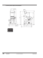
10. Layout
.......................................................................................................................... 39
11. Accessories, Overview .................................................................................................... 45
11.1 Pre-setting of rotating knives, granulator with open cutter ................................ 46
– Setting up the knives .......................................................................................... 46
– Installing of pre-set knives .................................................................................. 46
11.2 Third fixed knife, removal, installation .................................................................... 47
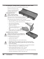
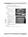
11.3 Band conveyor ............................................................................................................ 48
11.3.1 Spare parts list for the band conveyor ...................................................... 50
12. Transport and storage .................................................................................................... 51
A. Customer service ............................................................................................................ A-1
A. Warranty information ...................................................................................................... A-2
UGG003/0398
CF Series Granulators
i
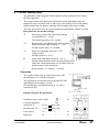
1. Introduction
This manual applies to theCF series of Conair granulators.
Model nos. CF-810, CF-814 and CF-819 specify the size of the cutting chamber.
Supplementary designations specify:
K
U
KU
KUB
KUP
Ð
Ð
Ð
Ð
Ð
Noise encapsulated machine
Machine with extraction fan
Noise encapsulated machine with extraction fan
Noise encapsulated machine with conveyor
Noise encapsulated machine for sheet material/profiles
Read the Manual before installing and using the machine.
Be careful when the knives are accessible, they are sharp, and
can cause personal injury!
These Conair granulators are designed for granulating injection molded, blow
molded and extruded plastic parts and scrap.
The size and performance of the granulators are designed to suit the type of
waste material.
Approval must be obtained from Conair for granulating other products
and materials for the warranty conditions to apply.
The granulators are designed so that maintenance and cleaning can be done
quickly and easily, both routine maintenance and changing of materials.
All service must be done by trained service personnel.
This Manual contains instruction for both handling and service.
Chapter 7 contains instructions directed towards service personnel.
Chapter 11 contains accessory equipment for the machine.
Other chapters contain instructions for the operator.
The granulators are delivered with an Instruction Manual and touch-up paint.
Any modifications or conversions of the machines must be approved by Conair.
This is to prevent injuries. The machine warranty and product assurance would
otherwise be rendered void.
Please address any queries to the local Conair representative or Conair
customer service.
UGG003/0398
CF Series Granulators
INTRODUCTION
1
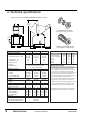
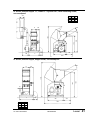
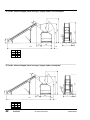
2. Technical specifications
GRANULATOR WITH STANDARD ROBOT/HAND FEED HOPPER
74.8 in.
{1900 mm}
D
E
STANDARD OPEN ROTOR
with scissor-cutting, slant knives
A
2 in.
{50 mm}
C
B
58.7 in. {1490 mm}
MODELS
Performance characteristics
Maximum throughput* lbs/hr {kg/hr}
Cutter chamber opening in. {mm}
Low speed rotor rpm
High speed rotor rpm
Motor power† Hp
Rotor type
Screen mesh sizes
Dimensions inches {mm}
A - Height
B - Width
C - Depth
D - Feed chamber width
E - Feed chamber height
Weight lbs {kg}
Installed
Shipping
Blades
Number of rotating knives
Number of fixed knives
Voltages Total amps based on cutter speed‡
208V/3 phase/60 hz
230V/3 phase/60 hz
460V/3 phase/60 hz
575V/3 phase/60 hz
Noise level§
With no soundproofing
With standard soundproofed hopper
With optional soundproofed base
2
CF-810
CF-814
CF-819
OPTIONAL STAGGERED ROTOR
with disposable, cassette knives
MOTOR OPTIONS
●=standard o=optional
330 {150}
330 {150}
330 {150}
8.7 x 9.5
8.7 x 14.2
8.7 x 18.9
{220 x 240}
{220 x 360}
{220 x 480}
312
312
312
487
487
487
5
7.5
7.5
open rotor, standard
(staggered rotor, optional)
0.16, 0.24, 0.31, 0.39, 0.47 and 0.67 in.
{4, 6, 8, 10, 12 and 17 mm}
58.3 {1480}
26.8 {680}
53.1 {1350}
9.4 {240}
8 {203}
58.3 {1480}
31.5 {800}
53.1 {1350}
14.2 {360}
8 {203}
58.3 {1480}
36.2 {920}
53.1 {1350}
18.9 {480}
8 {203}
925 {420}
1015 {460}
1158 {525}
3x2
2
low high
17.0 16.0
15.8 14.0
7.9
7.0
6.3
5.6
SPECIFICATIONS
3x3
2
low high
27.6 21.5
25.0 20.0
12.5 10.0
9.9
8.0
3x4
2
low high
27.6 21.5
25.0 20.0
12.5 10.0
9.9
8.0
5 Hp, low speed
7.5 Hp, low speed
5 Hp
7.5 Hp
10 Hp
15 Hp
CF-810 CF-814 CF-819
●
o
o
o
o
o
N/A
●
N/A
●
o
o
o
o
o
o
o
o
SPECIFICATION NOTES:
* Throughputs are provided as a capacity guideline
only. Throughput will vary according to the size,
shape, thickness and properties of the material to be
cut, as well as the desired size of the granulate.
Consult Conair for a material test or help determining
the correct granulator model for your application.
† The chart lists standard motor selections. Additional
motor sizes are listed under Motor Options.
‡ Amp loads are based on standard motor and cutter
speeds. For other configurations, consult Conair.
§ Noise level will vary according to material type being
processed and the granulator configuration. These
ranges are based on tests using SPI standards.
Specifications may change without notice. Check with a
Conair representative for the most current information.
90 to 95 dbA
85 to 90 dbA
80 to 85 dbA
CF Series Granulators
UGG003/0398
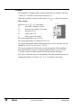
3. Function description
3.1 General
The granulator is designed for grinding plastic waste to
for recycling.
The plastic waste should be free from metal parts
and contamination before granulating.
The granulator is controlled by
start/stop controls on a control
panel.
H
A
B
G
C
Standard cutter
C
F
D
E
Open cutter
B
The plastics waste is feed into the hopper (A) and falls down into the cutter housing,
where rotating knives (B) cut the plastics waste against fixed knives (C) to granulate.
A perforated screen (D) determines the size of the granulate. The screen is located
in the lower section of the cutting chamber and can easily be changed to give the
desired granulate size.
The granulate passes the screen and falls down through the outlet chute/granule bin
(E) to the outlet pipe (F) for onwards transport.
Granulators with designation ÒUÓ are equipped with an extraction blower (G) which
sucks the granulate out to a cyclone (H) for separation of air. On granulator models
with designation ÒBÓ, the hopper is equipped with a conveyor belt. The conveyor
can be equipped with a metal detector.
After this, the granulate is ready for re-use in the production machine, or to be transported to a container for later use.
The granulator is easy to clean, with a folding hopper and also good accessibility for
maintenance. Knives on the staggered rotor are disposable and should be replaced
when necessary. The rotating knives on an open rotor can be re-sharpened. Grinding
is done in a special grinding jig. (The jig is not included when the granulator is
delivered, but is a very practical accessory.)
UGG003/0398
CF Series Granulators
DESCRIPTION
3
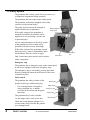
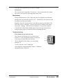
3.2 Safety system
The granulator has a safety system for to prevent access
to dangerous components during operation.
The granulator has knives that rotate at high speed.
The granulator is therefore equipped with a safety
system to avoid personal injury.
The safety system must not be changed or
modified under any circumstances.
Breaking key
Safety switch
If the safety system of the granulator is
changed or modified, the machine can be
dangerous to use, presenting a serious risk
of personal injury.
All care and maintenance to the safety system
of the granulator must be carried out by
personnel with the necessary knowledge.
If the safety system of the granulator is modified in any way, ConairÕs responsibility under
the Machinery Directive ceases to apply.
Main switch
Emergency
stop
Only Conair spare parts must be used to replace
safety components.
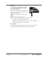
Emergency stop
The granulator has an emergency stop on the control panel.
It can also be equipped with extra emergency stops.
The emergency stop is activated by pressing the button.
Reset by turning the button in the direction of the arrow
(counterclockwise).
Safety switch
The granulator has safety switches of the
position switch type with breaking key:
Ð If a secured position is changed or
when a breaking key is undone,
it will break the current and the granulator stops.
This granulator has 2 safety switches:
1 at the hopper and 1 at the screen box
Breaking key
Safety switch
Emergency stop
Safety switch
Main switch
Check the wiring diagram (chapter 9) to
see how many safety switches the granulator is equipped with.
4
SAFETY SYSTEM
CF Series Granulators
UGG003/0398
Star knob
The star knob for the hopper and screen box
is a very important component in the safety
system of the granulator.
It should take such a long time for the knob/screw
to be undone, that the cutter has stopped before the
granulator can be opened.
NOTE! The length of the screw must never be
changed.
NOTE! The screw can not be removed.
The screen is hardened and the knob is permanently attached.
Ð To change a star knob, please contact Conair.
Ð NOTE! If the star knob is modified in any way, ConairÕs responsibility
under the Machinery Directive ceases to apply.
Before starting:
The star knobs on the hopper and screen box must be fully tightened to stop.
The granulate bin should be installed and the door shut and locked.
UGG003/0398
CF Series Granulators
SAFETY SYSTEM
5
4. Safety instructions
Conair granulators are designed for granulating injection moulded, blow moulded and
extruded plastic waste.
The specific technical data for this machine, concerning power and perfor-mance etc.
is described in detail in chapter 2.
The granulator is equipped with safety switches, which are described in
chapter 3.2.
Follow the instructions in this manual to avoid personal injury and damage
to machine components.
Always follow these safety measures when handling the granulator.
¥
Electrical installation must only be done by a competent electrician!
¥
Before the granulator is opened for servicing and maintenance.
Always disconnect the power with both the main switch and the
switch on the granulator.
¥
Never put any part of your body through the granulator openings, unless
both the main switch and the switch on the granulator are in ÒOffÓ (0) position.
¥
Be careful with the knives, they are sharp and can cause personal injury.
¥
If the rotor must be turned manually Ð do this with great care!
¥
Observe care when opening or closing the hopper and screenbox, so as not to
trap parts of the body.
¥
The granulator should not be able to start before the hopper and screen box
are properly closed.
¥
Never remove protective guards or pipes adjacent to the outlet/granule bin.
¥
Granulators with belt conveyors! Observe care so that conveyor belts with
dogs do not grip clothing, or arms and feet.
¥
During maintenance, pull out the plug on the distribution box.
DANGER! High voltage!
This sign is on the door to the distribution box and the connection
boxes.
DANGER! Cutting or pinch risk!
This sign is placed where there is a risk of being cut or pinched.
DANGER! Be careful!
This sign is located by all danger areas, where care and extra attention is required.
6
SAFETY
CF Series Granulators
UGG003/0398
5. Installation
Read through the whole of chapter 5 before installing the machine! All instructions
must be followed in the given order to avoid injury or damage.
Be careful with the knives, they are sharp and can cause personal injury.
The granulator must only be connected to the mains by a competent electrician.
5.1
Pre-start checks
¥
The unpainted parts of the machine are protected with oil prior to delivery and
transport Clean the granulator from rust protection agent before it is used.
¥
Check the knife clearance and tightening torque on the bolts for the knives. Refer
to installation of knives in chapter 7.
5.1.1 Two hours after first start
Check the knife clearance again and the tightening torque of the knife retentio
screws. Check the screws for both the fixed and rotating knives.
5.2
Electrical connection
The granulator should be connected by a competent electrician.
¥
Connect the granulator to the main power supply. The wiring diagram indicates
the fuse sizes, see chapter 9.
¥
The granulator is delivered with electrical equipment connected for clock-wise
phase rotation. Check with a phase sequence indicator and connect the granulator
with clockwise phase rotation.
Check the direction of rotation of the granulator motor:
¥
Make sure that the main switch beneath the control panel is ÒOnÓ (1).
¥
Check that the emergency stop is not activated.
¥
Check that the star knobs on the hopper and screen box locks are fully tightened
to stop.
¥
Undo and remove the upper panel on the right hand side of the granulator.
¥
Press ÒStartÓ
¥
Check that the granulator motor rotates in the direction indicated by the arrow on
the cutter pulley.
¥
Granulator with blower, Ð check that the direction of rotation of the blower corresponds with the arrow on the cover.
NOTE! The blower blows even if the direction of rotation is wrong.
¥
Granulator with conveyor belt, Ð check the direction of the conveyor belt.
If any direction of rotation should be incorrect:
¥ Press the stop button.
¥ Switch off the main switch.
¥
UGG003/0398
Switch two incoming phases.
CF Series Granulators
INSTALLATION
7
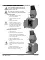
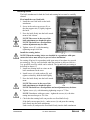
5.3
Opening of hopper, screen box and granule bin
Before opening the hopper, granule bin and
screen box, switch both the main switch and
granulator switch ÒOffÓ.
Be careful when the knives are accessible.
They are sharp and can cause personal injury.
A
Opening the hopper
B
1. Check that the hopper is empty,
then stop the granulator.
F
2. Undo the star knobs (A) on the
hopper.
3. Undo the tip catch (B).
NOTE! The hopper is counterbalanced with one alternative two
gas springs, but hold the hopper
at the same time, so that it does
not fall down out of control.
4. Open/fold the hopper backwards.
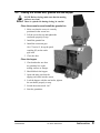
C
D
Opening the screen box
G
E
1. Open the door (C).
2. Undo and pull out the extraction pipe
from the left-hand side of the granulator.
Alt. CF series-U, undo the quick coupling (D)
on the outlet pipe stub.
A
3. Remove the granule bin (E).
B
4. Undo the star knobs (F) for the screen
box (G)
NOTE! Hold the screen box at the same
time, so that it does not fall down out of
control.
5. Fold the screen box down.
The screen is now accessible and can be
lifted out for changing or cleaning.
F
G
D
E
8
INSTALLATION
CF Series Granulators
UGG003/0398
5.4
Closing the screen box, granule bin and hopper
NOTE! Before closing, make sure that the mating
surfaces are clean!
There is a pinch risk during closing, be careful.
Close the screen box and install the granule bin
1. Make sure that the screen is correctly
positioned in the screen box.
2. Lift the screen box up and tighten the
star knobs properly to stop.
3. Install the granule bin.
4. Install the extraction pipe.
Alt. CF series-U, do up the quick
coupling (D) on the outlet
pipe stub.
5. Close the door.
Close the hopper
1. Check and make sure that
no granulate lies on the
mating surfaces or flanges.
2. Shut/fold back the hopper.
3. Open and make sure that the
tipping catch falls into the cutout.
4. Lock the hopper with the star knobs, tighten
the star knobs properly to stop.
5. Switch the main switch ÒOnÓ.
6. Start the granulator.
UGG003/0398
CF Series Granulators
INSTALLATION
9
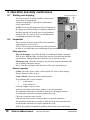
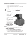
6. Operation and daily maintenance
6.1
Starting and stopping
The main switch is located beneath the control panel
on the front of the granulator.
Stop Start Emergency
stop
Starting and stopping is controlled by push buttons
on the control panel.
NOTE! Never stop the granulator before all material in
the hopper and cutter housing is completely granulated.
Residual material will clog the rotor in the granulator
during re-start. The motor will be overloaded and the
overloading protection will trigger.
6.2
Inspection
There must be no plastic material left in the granulator
when inspection is carried out.
NOTE! All servicing must be done by trained personnel
in order to avoid personal injury and damage to the machine.
Daily inspection
Main switch
Flaps in the hopper. Check that the flaps are undamaged. Replace damaged
flaps at once. Damaged flaps can drop down into the cutter housing and damage the knives. Damaged flaps also entail the risk of material ejection.
Emergency stop. Check the emergency stop function. Start the granulator and
stop it with the emergency stop(s).
Reset. Turn the stop button in the direction of the arrow (anticlockwise).
Weekly inspection
Cables. Check the electric cables of the machine for wear or other damage.
Replace damaged cables at once.
Safety switches. Check the safety switch functions.
This granulator has 2 safety switches:
1
at the hopper
1
at the screen box
Check the hopper«s safety switch.
Undo the star knobs on the hopper, and try to start the granulator.
The granulator should not be possible to start before the hopper has been
closed and the star knobs are properly tightened to stop.
Check the screen box safety switch.
Undo the star knobs on the screen box and try to start the granulator.
The granulator should not be possible to start before the screen box has been
closed and the star knobs are properly tightened to stop.
NOTE! The granule bin should be installed, and the door closed and locked.
10
OPERATION/MAINTENANCE
CF Series Granulators
UGG003/0398
Monthly inspection
Check that the V-belts are undamaged.
Check the V-belt tension every 6 months, see chapter 7.3 ÒTransmissionÓ.
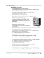
6.3
Cleaning
Clean at colour change, monthly or at least once/300 hours.
Be careful when the hopper have been opened. The knives are now accessible, they are sharp, and can cause personal injury.
1. Check that the hopper is empty, then stop the granulator.
Switch ÒOffÓ both the main switch and the switch on
the granulator.
2. Clean the outside of the hopper.
3. Undo the star knobs on the hopper.
4. Undo the tip chatch.
NOTE! The hopper is counterbalanced with one alternative two gas springs, but hold the hopper at the same
time, so that it does not fall down out of control.
5. Open/fold the hopper backwards.
6. Clean the hopper«s opening.
7. Lift out and clean the inner and
outer flaps.
8. Open the door.
9. Undo and pull out the extraction
pipe from the left-hand side of the
granulator.
Alt. U model, undo the quick coupling
on the outlet pipe stub.
10. Remove the granule bin.
11. Undo the star knobs for the screen box.
NOTE! Hold the screen box at the same time,
so that it does not fall down out of control.
12. Fold the screen box down.
A
13. Undo and clean the screen.
14. Undo and remove the blue screws (A)
for the bearing cleaning holes.
15. Blow through the holes with compressed
air and rotate the cutter at least one turn.
NOTE! When the cutter is rotated
manually, do this with great care.
The knives are sharp and can cause
personal injury.
UGG003/0398
CF Series Granulators
OPERATION/MAINTENANCE
11
6.3
Cleaning (continued)
NOTE! Use protective goggles and make sure that no
material blows into the safety switches!
16. Clean the granule bin and the screen box.
17. Clean the cutter housing inside and outside.
18. Clean any transport pipes, blower and cyclone.
Re-install after cleaning
1. Install the blue screws.
2. Install the screen in the screen box.
3. Lift up the screen box and and tighten the star knobs to stop.
4. Install the granule bin.
5. Install the extraction pipe.
Alt. CF series-U, do up the quick coupling on the outlet pipe stub.
6. Close the door.
7. Close the hopper. Check and make sure that no granulate remains on the
mating flanges or surfaces.
8. Open and make sure that the tipping catch falls into the cutout.
9. Lock the hopper with the star knobs, tighten the knobs properly to stop.
12
OPERATION/MAINTENANCE
CF Series Granulators
UGG003/0398
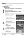
6.4
Fault-finding
The granulator does not start
¥
Check that the emergency stop is not activated.
Reset by turning the button(s) in the direction of the arrow (counterclockwise).
¥
Check that the hopper is properly closed.
The granulator will not start if the hopper not is properly closed.
Tighten the star knobs properly to stop.
¥
Check that the screen box is properly closed.
The granulator will not start, if the screen box not is properly closed.
Tighten the star knobs properly to stop.
¥
Check the overload circuit breaker for the motor.
The motor has an overload circuit breaker, F1, in
the distribution box, which trips if you jam or overload the motor.
A
B
This is indicated in the window (A) which shows Ò0Ó.
Reset, press the ÒResetÓ button (B).
Check that there is no material left in the granulator
before restarting.
¥
Granulator with blower (CF series-U). Check the blower overload circuit breaker.
The granulator will not start if the blower does not start.
The blower motor has an overload circuit breaker, F2, in the distribution box,
which trips if you jam or overload the blower.
This is indicated in the window (A) which shows Ò0Ó.
Reset, press the ÒResetÓ button (B).
Check that there is no material left in the granulator before re-starting.
¥
Granulator with conveyor belt (CF series-KUB), if the conveyor belt does not
start Ð check the conveyor belt overload circuit breaker.
The conveyor belt motor has an overload circuit breaker, F3, in the distribution
box, which trips if you jam or overload the conveyor belt.
This is indicated in the window (A) which shows Ò0Ó.
Reset, press the ÒResetÓ button (B).
Check that there is no material left on the band before re-starting.
¥
Check the granulator knives and knife tolerance.
If the granulator knives are blunt and unsharpened, or if the knife clearance is
incorrect, this can result in stoppage. The granulator motor overload circuit breaker will trip. Check the knives. Sharpen or replace the knives, or adjust the knife
clearance, see next chapter.
Check also the wiring diagram in chapter 9; supplements and deviations may be applicable.
UGG003/0398
CF Series Granulators
OPERATION/MAINTENANCE
13
7. Service
All service must be carried out by trained personnel in order to avoid personal
injury or damage to the machine.
7.1 Changing knives
Removing the knives
Check the screen for wear when the knives are changed. Change the screen
when the holes begin to be pear shaped.
Be careful when handling the knives, they are sharp and can cause personal injury. Use protective gloves!
Each time the knives are changed, the knife fastening screws must be
replaced by new ones.
Changing the knives.
Open the hopper and any door. Remove the granule bin, then fold the screen
box down and lift it out Ð see chapter 5.3.
Removing the rotating knives.
1. Remove the screws (A) and washers (B),
2 each per knife. The knives are now loose.
2. Lift out the rotating knives.
3. Clean the surfaces where the knives were
located.
Removing the fixed knives.
4. Undo the socket cap screws (C) on the
front knife support rule (D).
A, B
5. NOTE! Hold the fixed knife and support
rule before removing the last screw.
6. Lift out the fixed knife together with the
support rule.
7. Clean the knife location.
8. Put the support rule back loosely.
9. Undo and remove the socket cap screws
(E) on the rear knife support rule (F).
10. NOTE! Hold the fixed knife and support
rule before removing the last screw.
11. Lift out the fixed knife together with the
support rule.
12. Clean the knife location.
13. Put the support rule back loosely.
E
14
SERVICE
CF Series Granulators
F
D
C
UGG003/0398
Installing knives
The knife attachments for both the fixed and rotating knives must be carefully
cleaned.
First install the rear, fixed knife
1. Install the rear fixed knife on the knife
attachment.
2. Screw in the socket cap screws (E), so
that the support rule (F) lightly supports
the knife.
3. Press the knife firmly into the knife attachment to bed it down.
NOTE! The screws in the rear of the
knife attachment are bonded in place.
NOTE! The knife has a fixed position
and no adjustment may be done.
4. Tighten screws (E), with alternating
tightening torque to 40 Nm.
Install the rotating knives.
E
F
NOTE! When the rotating knives are installed in a granulator with open
cutter, the knives must always be pre-set before installation!
Pre-setting of knives for a granulator with open cutter is best done in a special
pre-setting jig. The jig is not included when the machine is delivered, but is a
very practical accessory which can be ordered. The jig and knife pre-setting is
described in chapter 11.
5. Install one rotating knife at a time on the
knife attachment on the rotor.
6. Install screws (A) with washers (B), and
tighten so that they hold the knife lightly.
7. Press the knife firmly into the knife attachment.
NOTE! The screws in the rear of the
knife attachment are bonded in place.
A, B
NOTE! The knife has a fixed position and no adjustment may be done.
8. Tighten screws (A), with alternating tightening torque to 75 Nm.
NOTE! Granulators with open cutter Ð tighten the screws (A) with alternating increased torque to 220 Nm.
9. Check that the rotating knife can pass the rear fixed knife freely.
If the knife can not pass freely Ð undo screws (A) and press the rotating
knife firmly into the knife attachment.
Undo screws (E) and press the fixed knife firmly into the knife attachment.
UGG003/0398
CF Series Granulators
SERVICE
15
10. Check the knife clearance with a feeler
gauge. The clearance should be 0.20 0.30 mm, check at the outer edges of the
knives.
11. Install all the rotating knives.
12. Press the knife firmly into the knife attachment.
13. Tighten the screws (A) with alternating
increased torque to 75 Nm.
A, B
NOTE! Granulators with open cutter Ð tighten the screws (A) with alter-nating increased torque to 220 Nm.
14. Check that each rotating knife can pass the rear fixed knife freely.
If any rotating knife can not pass freely Ð undo the screws (A) and press the
knife firmly into the knife attachment.
15. Check the clearance of each rotating knife with a feeler gauge The clearance
should be 0.20 - 0.30 mm, check at the outer edges of the knives.
Then install the front, fixed knife
16. Install the knife in the knife attachment.
17. Screw in the socket cap screws (C) and
tighten so that the support rule (D) lightly
supports the knife.
18. Press the knife firmly into the knife attachment.
NOTE! The screws in the rear of the
knife attachment are bonded in place.
NOTE! The knife has a fixed position
and no adjustment may be done.
19. Tighten the screws (C), with alternating
tightening torque to 40 Nm.
20. Carefully check that all rotating knives
can pass the front fixed knife.
If any knife can not pass the front fixed
D
C
knife freely
Ð undo the screws (C) and press the knife firmly into the knife attachment.
21. Check the clearance of each rotating knife with a feeler gauge The clearance
should be 0.20 - 0.30 mm, check at the outer edges of the knives.
22. Re-check the tightening torque of all rotating knives (75 Nm; granulator
with open cutter 220 Nm).
23. Re-check the tightening torque of the front and rear fixed knives (40 Nm).
16
SERVICE
CF Series Granulators
UGG003/0398
7.2 Sharpening knives
NOTE! Only rotating knives for granulators with an open rotor can be sharpened.
Other knives are disposable and are replaced when necessary.
Sharpening knives - granulators with open cutter
Keep the complete set of knives together as one unit.
NOTE! To avoid unbalance, all the knives belonging to the cutter must be
ground exactly the same.
Be careful when handling the knives, they are sharp and can cause personal
injury.
NOTE! Get an experienced craftsman to sharpen the knives.
Only sharpen the marked surfaces and respect the given dimensions!
The knives must be sharpened exactly, to get the correct cutting and relief angles.
Otherwise the efficiency of the granulator will be impaired.
The knife must be cooled during sharpening. The knives must not be burned or
blued under any circumstances, otherwise they will loose their hardness and durability.
If the knife is blued or burned, they can not be repaired by grinding down the
blued or burned area. The hardened knife is then completely spoiled and has lost
all its hardness and durability.
Use the Conair grinding jig SF-20 (accessory, art no. 3-030324) and a surface
grinder with magnetic table. The jig gives exact correct cutting and relief angles.
Grind
¥ Remove the knives adjustment screws.
¥ Grind the worst knife to make the relief angle 35¡.
¥ Tighten the knife in the right-hand position in the
jig, using spacer ÒAÓ beneath the rear of the knife
(see illustration).
Spherical washers should be used when tightening
the knife.
A
¥ Grind until all the irregularities on the knife edge
Grind
have disappeared.
¥ Retain the settings of the surface grinder and grind
all the other knives exactly the same.
¥ Grind the cutting angle of the knives to 30¡
¥ Remove spacer ÒAÓ beneath the knife.
¥ Tighten the knife and grind until the cutting
edge is 3 mm wide.
35o
¥ Retain the settings of the surface grinder and
30o
grind all the other knives exactly the same.
Min. 56 mm
¥ The knives can be sharpened up to the limits
shown in the display.
3 mm
After this, the knives are used up and must be
replaced by new ones.
UGG003/0398
CF Series Granulators
SERVICE
17
7.3 Transmission
Vee belts, inspection and adjustment
The granulator is driven by 3 V-belts.
Checking the V-belts
The tension and condition of the V-belts must be checked after 20 - 30 hours
of operation at full load.
After this, check the V-belts for damage once a month.
Check the belt tension every 6 months.
¥
Undo and remove the upper panel on the right-hand side of the granulator.
¥
Rotate the V-belts a few turns.
Check that the belts are intact, undamaged and uncracked.
WARNING! Pinch risk between pulleys and V-belts.
¥
Check belt tension and adjust if necessary.
Motors up to 7.5 kW:
¥ Load each one of the belts in turn with 20 N,
centrally between the cutter and belt pulleys.
It should not be possible to depress the belt more
than about 5 mm.
Motors up to 7,5 kW
L = 5 mm; F = 20 N
11 kW motor
F = 27 N
L = 5 mm;
11 kW motor:
¥ Load each one of the belts in turn with 27 N, centrally between the
cutter and belt pulleys.
It should not be possible to depress the belt more than about 5 mm.
V-belt adjustment
18
¥
¥
Remove the upper panel on the right-hand side of the granulator.
CF series-K, remove the rear guard plate
above the motor and open the door.
¥
Undo and remove the extraction pipe.
Alt. CF series-U, undo the quick coupling
on the outlet pipe stub.
SERVICE
CF Series Granulators
UGG003/0398
7.3 Transmission
B
(continued)
B
A
¥
Remove the granule bin.
¥
Undo the motor screws (A) lightly, 4 pcs.
¥
Adjust the belt tension by increasing/reducing the distance of the motor to the
cutter pulley, using the motor adjustment screws (B), 2 pcs.
¥
Tighten the motor screws (45 Nm torque)
¥
If the belt tension is adjusted, the belt need to be re-checked after 20 - 30 hours
at full load.
7.4 Lubrication
Cutter housing
The bearings in the cutter housing are permanently greased, and do not need greasing in normal circumstances.
UGG003/0398
CF Series Granulators
SERVICE
19
7.5 Cutter pulley/Motor pulley
The upper panel on the right-hand side of the granulator must be removed to
remove/install the cutter or motor pulleys.
This makes the cutter and motor pulleys accessible.
Removal
Cutter pulley
The pulley is mounted with a compression bush.
¥
Undo all screws a few turns (8 pcs.)
¥
Remove two screws.
¥
Put a drop of oil into the extractor
hole (A), and insert the two screws.
¥
Tighten the screws, using progressively
increased torque until the compression
bush comes away from the shaft.
¥
Lift off the cutter pulley, complete with the
compression bush, from the shaft.
Motor pulley
¥
Undo the socket cap screw on the pulley.
¥
Remove the pulley with a puller.
Installing
Motor pulley
Lift the pulley onto the motor shaft, make sure that the key fits.
¥
A
Tighten the pulley with the socket cap screws on the shaft, 120 Nm.
Cutter pulley
The pulley is fitted with a compression bush.
20
¥
Clean and degrease the cutter pulley.
¥
Oil the cutter shaft.
¥
Oil the screws and fit the compression bush lightly on the pulley.
¥
Lift the pulley on to the cutter shaft.
¥
Make sure that the pulleys line up.
¥
Tighten the screws in the compression bush.
Tighten the screws alternately with the same torque, progressively
increasing the torque to 20 Nm.
¥
Tap the compression bush between the shaft and the screws.
Use a block of wood or plastic.
¥
Tighten the pulley with the compression bush.
Tighten the screws with alternating increased torque to 40 Nm.
SPARE
PARTS
CF Series Granulators
UGG003/0398
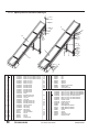
8.
Spare parts list
Overview
The granulator is divided into the following modules:
Page
8.1
Cutting chamber ........................................................................ 22
8.2
Staggered rotor .......................................................................... 23
8.3
Open rotor .................................................................................. 24
8.4
Knives ........................................................................................ 25
8.5
Knives, open rotor ...................................................................... 25
8.6
Transmission .............................................................................. 26
8.7
Screen ........................................................................................ 27
8.8
Screen box .................................................................................. 27
8.9
Outfeed, Granule bin manual .................................................... 28
8.10
Outfeed, vaccum suction/blower F-7/F-15 ................................ 29
8.11
Hopper ...................................................................................... 30
8.12
Hopper -KUB ............................................................................ 31
8.13
Hopper rear-KUP ........................................................................ 32
8.14
Hopper device ............................................................................ 33
8.15
Safety ........................................................................................ 33
8.16
Sound cabin ................................................................................ 34
8.17
Enclosure/Body ........................................................................ 35
Ordering spare parts
Only use spare parts from Conair when replacing machine parts.
Orders should go to the representative in the country where the machine
was purchased.
When ordering, the following should be specified:
¥
Machine designation, as specified on the machine plate.
¥
Serial number, as specified on the machine plate.
¥
Part number, as specified in the spare parts list.
¥
Quantity, as specified in this spare parts list.
UGG003/0398
CF Series Granulators
SPARE
PARTS
21
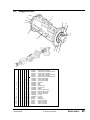
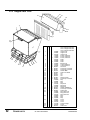
8.1
Cutting chamber
17
16
15
1
5
3
9
13
18
10
11
2
4
6
7
12
8
14
Pos
1
2
Qty.
1
1
1
3
1
1
1
4
1
1
1
1
1
1
1
1
1
1
1
1
5
1
1
1
1
1
1
6
1
1
1
1
1
1
7
1
1
1
1
1
1
Art. no.
3-029705
3-030254
3-029706
3-030255
3-029707
3-030256
1-029513
4-030700
1-029514
4-030701
1-029507
4-030702
1-029508
4-030703
1-029509
4-030704
1-029510
4-030705
1-029511
4-030706
1-029512
4-030707
2-029518
4-030708
2-029519
4-030709
2-029520
4-030710
2-029521
4-030711
2-029522
4-030712
2-029523
4-030713
Description
Cutter housing CF-810
– ” – CF-810 hardened
Cutter housing CF-814
– ” – CF-814 hardened
Cutter housing CF-819
– ” – CF-819 hardened
Side, right
Side, right
Side, left
Side, left
Front side
Front side
Front side
Front side
Front side
Front side
Rear side
Rear side
Rear side
Rear side
Rear side
Rear side
Support rule, rear
Support rule, rear
Support rule, rear
Support rule, rear
Support rule, rear
Support rule, rear
Support rule, front
Support rule, front
Support rule, front
Support rule, front
Support rule, front
Support rule, front
Pos
8
Qty.
1
1
1
9
10
11
12
13
14
15
1
1 1
1 1 1 1 1 1
8 8 8 8 8 8
14 14 14 14 14 14
4 4 4 4 4 4
4 4 4 4 4 4
4 4 4 4 4 4
3-029709
3-030258
3-029710
3-030259
16
1
1
1
1
1
1
17
1
1
1
1
1
18
22
SPARE
PARTS
Art. no.
3-029705
3-030254
3-029706
3-030255
3-029707
3-030256
3-029524
3-029525
3-029526
4-026380
950079
940005
940104
940213
940743
3-029708
3-030257
2
2
2
CF Series Granulators
2
2
1
2
1-029554
4-030243
1-029555
4-030244
1-029556
4-030245
2-029557
4-030246
2-029558
4-030247
2-029559
4-030248
940742
Description
Cutter housing CF-810
– ” – CF-810 hardened
Cutter housing CF-814
– ” – CF-814 hardened
Cutter housing CF-819
– ” – CF-819 hardened
Support, screen box
Support, screen box
Support, screen box
Lid
Cylindric pin
Socket cap screw
Socket cap screw
Socket cap screw
Stop screw
Cutter housing CF-810 w 3:rd knife
Cutter housing CF-810 w 3:rd knife
hardened
Cutter housing CF-814 w 3:rd knife
Cutter housing CF-814 w 3:rd knife
hardened
Cutter housing CF-819 w 3:rd knife
Cutter housing CF-819 w 3:rd knife
hardened
Rear for 3:rd fixed knife
Rear for 3:rd fixed knife
Rear for 3:rd fixed knife
Rear for 3:rd fixed knife
Rear for 3:rd fixed knife
Rear for 3:rd fixed knife
Support rule for 3:rd fixed knife
Support rule for 3:rd fixed knife
Support rule for 3:rd fixed knife
Support rule for 3:rd fixed knife
Support rule for 3:rd fixed knife
Support rule for 3:rd fixed knife
Socket cap screw
UGG003/0398
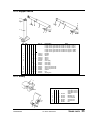
8.2
Staggered rotor
12
2
8
15
5
3
14
6
10
7
11
4
13
9
1
Pos
1
Qty.
1
2
3
2
2
4
6
5
6
1
1
7
1
8
9
10
11
12
13
14
15
1
1
2
2
6
6
8
4
1
2
1
1
3
2
3
2
2
9
6
1
1
1
1
UGG003/0398
2
9
1
1
1
1
1
1
2
2
6
6
8
4
1
4
12
1
1
1
1
2
2
6
6
8
4
1
4
2
12
1
1
1
1
1
1
2
2
6
6
8
4
1
1
2
2
6
6
8
4
1
1
1
2
2
6
6
8
4
Art. no.
3-29702
3-30260
3-29703
3-30261
3-29704
3-30262
1-029530
1-029531
1-029532
3-029501
3-029502
4-030249
3-029504
4-030250
4-029529
2-029505
2-030714
2-029506
2-030715
3-029527
4-029528
960182
960183
940579
940007
940071
940032
Description
Cutter CF-810 3-blade
Cutter CF-810 3-blade hardened
Cutter CF-814 3-blade
Cutter CF-814 3-blade hardened
Cutter CF-819 3-blade
Cutter CF-819 3-blade hardened
Cutter shaft 3-blade
Cutter shaft 3-blade
Cutter shaft 3-blade
Segment
Ring
Ring
Support rule
Support rule
Sleeve
Plummer block, right
Plummer block, right
Plummer block, left
Plummer block, left
Lid, left
Lid, right
Bearing
Sealing ring
Socket cap screw
Socket cap screw
Socket cap screw
Socket cap screw
CF Series Granulators
SPARE
PARTS
23
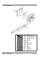
8.3
Open rotor
5
10
2
1
6
13
4
11
3
12
7
8
9
Pos
1
Qty.
1
1
1
2
2
3
4
1
1
5
1
6
7
8
9
10
11
12
13
1
1
2
2
6
6
8
4
SPARE
PARTS
1
2
2
2
1
1
1
1
24
1
2
1
1
1
1
1
1
2
2
6
6
8
4
1
1
1
1
2
2
6
6
8
4
1
2
1
1
1
1
1
1
2
2
6
6
8
4
1
1
2
2
6
6
8
4
1
1
1
2
2
6
6
8
4
CF Series Granulators
Art. no.
3-30113
3-30263
3-29753
3-30264
3-30114
3-30265
1-030104
1-029743
1-030106
3-029502
4-030249
4-029529
2-029505
2-030714
2-029506
2-030715
3-029527
4-029528
960182
960183
940579
940007
940071
940032
Description
Cutter CF-810 3-blade
Cutter CF-810 3-blade
Cutter CF-814 3-blade
Cutter CF-814 3-blade
Cutter CF-819 3-blade
Cutter CF-819 3-blade
Cutter 3-blade
Cutter 3-blade
Cutter 3-blade
Ring
Ring
Sleeve
Plummer block, right
Plummer block, right
Plummer block, left
Plummer block, left
Lid, left
Lid, right
Bearing
Sealing ring
Socket cap screw
Socket cap screw
Socket cap screw
Socket cap screw
open
open hardened
open
open hardened
open
open hardened
UGG003/0398
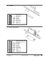
8.4
Knives
1
45
2
3
6
Pos
1
2
Qty.
6
2
Art. no.
9 12
2
2
3
1
1
4
5
6
7
1
12 18 24
12 18 24
8 12 16
4 6 8
3-029503
2-029515
2-029516
2-029517
2-029515
2-029516
2-029517
940004
940031
940778
940779
7
Description
Note
Granulator CF-810
Granulator CF-814
Granulator CF-819
Knife, rotating
Knife, fixed
Knife, fixed
Knife, fixed
Knife, third fixed
Knife, third fixed
Knife, third fixed
Socket cap screw
Washer
Socket cap screw
Socket cap screw for 3:rd fixed knife
8.5 Knives, open cutter
8
12
11
13
9
14
10
15
Pos
8
Qty.
Art. no.
6
6
6
9
2
2
2
10
1
1
11
12
13
14
15
12
12
12
12
8
4
12
12
12
12
12
6
UGG003/0398
1
12
12
12
12
16
8
3-030108
3-029750
3-030109
2-029515
2-029516
2-029517
2-029515
2-029516
2-029517
940776
4-029751
940302
940057
940057
940057
Description
Granulator CF-810
Granulator CF-814
Granulator CF-819
Knife, rotating
Knife, rotating
Knife, rotating
Knife, fixed
Knife, fixed
Knife, fixed
Knife, third fixed
Knife, third fixed
Knife, third fixed
Socket cap screw
Washer
Screw
Socket cap screw
Socket cap screw
Socket cap screw
Note
with open cutter
with open cutter
with open cutter
for 3:rd fixed knife
CF Series Granulators
SPARE
PARTS
25
8.6
Transmission
4
5
1
7
12
11
3
2
6
Pos
1
2
3
4
Qty.
1
1
2
1
Art. no.
1
1
2
1
1
2
1
1
2
1
1
2
1
1
1
5
6
7
8
9
10
11
12
26
SPARE
PARTS
1
1
3
4
6
2
1
1
1
1
3
4
6
2
1
1
1
1
3
4
6
2
1
1
1
1
3
4
6
2
1
1
1
1
1
3
4
6
2
1
1
1-29545
3-29546
3-29552
911189
911178
911171
911172
911177
930222
970214
930221
940092
940031
940744
940648
940051
CF Series Granulators
8
9
10
Description
Transmission 4,0 kW 1000 rpm 400 V
Transmission 5,5 kW 1000 rpm 400 V
Transmission 5,5 kW 1500 rpm 400 V
Transmission 7,5 kW 1500 rpm 400 V
Transmission 11,0 kW 1500 rpm 400 V
Cutter pulley
Motor pulley
Belt tensioner
Motor 4,0 kW
Motor 5,5 kW
Motor 5,5 kW
Motor 7,5 kW
Motor 11,0 kW
Coupling
Ring, polyester
V-belt
Screw
Washer
Screw
Washer
Socket cap screw
UGG003/0398
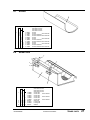
8.7
Screen
1
Pos
1
Qty.
Art. no.
1
1
1
1
3-29574
3-31688
4-30251
4-31691
3-29575
3-31689
4-30252
4-31692
3-29576
3-31690
4-30253
4-31693
1
1
1
1
1
1
1
1
Description
Granulator CF-810
Granulator CF-814
Granulator CF-819
Screen
Screen
stitch
Screen hardened
Screen hardened stitch
Screen
Screen
stitch
Screen hardened
Screen hardened stitch
Screen
Screen
stitch
Screen hardened
Screen hardened stitch
reduced
reduced
reduced
reduced
reduced
reduced
NOTE! Specify art no. and required hole diameter, Ø 4, 6, 8 or 10 mm.
8.8
Screen box
3
4
5
2
1
5
Pos
1
Qty.
Art. no.
1
1
1-29560
1-29656
1-29561
1-29657
1-29562
1-29658
950532
4-30327
4-30328
940155
1
1
2
3
4
5
2
1
1
4
UGG003/0398
2
1
1
4
1
1
2
1
1
4
Description
Note
Granulator CF-810
Granulator CF-814
Granulator CF-819
Screen box
Screen box
stitch reduced
Screen box
Screen box
stitch reduced
Screen box
Screen box
stitch reduced
Star knob
Locking bolt
Locking bolt
Washer
CF Series Granulators
SPARE
PARTS
27
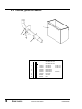
8.9
Outfeed, granule bin manual
1
4
5
6
3
2
Pos
1
Qty.
Art. no.
1
1
1
2
3
4
5
6
28
SPARE
PARTS
1
1
1
1
1
1-29577
1-29578
1-29579
3-30246
2-30248
2-30079
3-29752
3-30078
950095
940432
CF Series Granulators
Description
Granulator CF-810
Granulator CF-814
Granulator CF-819
Granule bin
Granule bin
Granule bin
Bracket D-50
Bracket D-50
Bracket D-50
Pipe D-50
Pipe D-50
Star knob
Rivet
Note.
manual 15 L
manual 22 L
manual 29 L
CF-810-K
CF-810-K
UGG003/0398
8.10 Outfeed, vaccum suction /blower F-7/F-15
27
25
26
12
19
7
23
15
4
20
3
2
5
6
1
24
17
14
21
13
11
16
18
Pos
1
Qty.
1
1
2
3
4
5
6
7
8
9
10
11
12
13
14
15
16
17
18
19
20
21
22
23
24
25
26
27
UGG003/0398
1
1
1
1
1
1
1
4
1
1
1
1
1
1
1
1
1
1
4
4
4
4
8
6
8
4
2
1
1
8
1
1
1
1
1
1
1
1
1
1
4
4
4
4
8
6
8
4
2
1
1
8
1
1
1
1
1
1
1
1
1
1
4
4
4
4
8
6
8
4
2
1
1
8
8
22
Art. no.
1
10
9
1-30082
1-29633
1-30087
4-30087
4-30077
3-29752
3-30078
2-30079
950095
920415
940432
3-29759
2-29639
3-30267
1-22825
3-13138
3-10332
4-24655
920415
920206
920421
940347
940004
940201
940426
940039
940015
940031
940592
940213
1-22824
970152
940147
Description
Note.
Granulator CF-810
Granulator CF-814
Granulator CF-819
Granule bin
vaccum/blower
Granule bin
vaccum/blower
Granule bin
vaccum/blower
Lid D-110
vaccum
Lid D-110
CF-810-K vaccum
Pipe D-50
vaccum
Pipe D-50
CF-810-K vaccum
Bracket D-50
vaccum
Star knob
Quick coupling ring
Rivet
Distance
Pipe stub D-100
Pipe stub, inlet
Holder, blower
Pipe stub, outlet
F7
Pipe stub, outlet
F15
Holder, blower
Quick coupling ring
Blower F7/D4
Blower F15/D6
Socket cap screw M10
Socket cap screw M10
Socket cap screw M10
Screw M8
Socket cap screw M6
Nut M10
Washer BRB
Washer BRB FZB
Socket cap screw M6
Cover, blower
Sealing ring
Screw
CF Series Granulators
SPARE
PARTS
29
8.11 Hopper
11
1
21
16
17
18
19
3
15
7
6
20
9
8
4
10
12
5
13
2
14
22
21
24
23
Pos
1
Qty.
Art. no.
1
1
1
2
1
1
1
3
1
1
4
5
6
7
8
9
10
11
12
13
30
1
1
1
2
6
2
4
1
1
1
SPARE
1
1
1
2
6
2
4
1
1
1
1
1
1
1
2
6
2
4
1
1
1
1-30614
1-29761
1-30618
1-29595
1-29596
1-29597
4-30495
4-29734
4-30628
4-29646
4-30327
4-30328
950532
940097
940071
940155
940696
970141
970218
PARTS
Description
Granulator CF-810
Granulator CF-814
Granulator CF-819
Hopper, front
Hopper, front
Hopper, front
Frame
Frame
Frame
Shaft
Shaft
Shaft
Bracket, key
Locking bolt M12
Locking bolt M12
Star knob
Socket cap screw M8
Socket cap screw M5
Washer BRB FZB
Stop screw
List
List
Pos
14
15
16
17
18
19
Qty.
1
1
1
1
1
1
Art. no.
1
1
1
1
1
1
1
1
1
1
1
1
20
1
1
21
22
23
4
1
1
4
1
1
4
1
1
1
24
1
CF Series Granulators
1
1
970148
4-30093
4-22129
940162
940662
2-30494
2-29787
2-30641
2-29789
2-29788
2-29790
940587
970141
2-30477
2-29780
2-29791
2-30484
2-29799
2-29798
Description
Granulator CF-810
Granulator CF-814
Granulator CF-819
List
Stop double
Distance
Washer BRB
Socket cap screw M8
Hopper table
Hopper table
Hopper table
Funnel
Funnel
Funnel
Socket cap screw M8
List
Flaps
Flaps
Flaps
Flaps, cloth
Flaps, cloth
Flaps, cloth
UGG003/0398
8.12 Hopper -KUB
1
4
2
Pos
1
3
Qty.
Art. no.
1
1
2
3
8
4
-
1
4
4
4
1
UGG003/0398
1
4
1
2-30673
2-30654
2-30666
940020
940097
940032
940070
970218
Description
Granulator CF-810
Granulator CF-814
Granulator CF-819
Sound trap
Sound trap
Sound trap
Washer AMF
Socket cap screw M8
Socket cap screw M8
Socket cap screw M8
List
CF Series Granulators
SPARE
PARTS
31
8.13 Hopper rear -KUP
23
22
24
26
11
1
27
18
19
20
21
25
17
15
16
Pos
3
1
Qty.
Art. no.
1
1
1
2
1
1
7
1
3
6
9
1
1
2
4
10
12
5
8
14
13
4
5
6
7
8
9
10
11
12
13
14
15
16
17
1
1
1
2
6
2
4
1
1
1
1
1
2
1
1
1
1
2
6
2
4
1
1
1
1
1
2
1
1
1
1
2
6
2
4
1
1
1
1
1
2
1
1
18
1
1
19
20
21
22
2
2
2
1
2
2
2
1
2
2
2
1
1
23
1
1
1
24
1
1
25
26
27
32
SPARE
PARTS
1
4
1
CF Series Granulators
1
4
1
1
1
4
1
2-29686
2-29661
2-30140
1-29598
1-29599
1-29600
4-29734
4-29596
4-30628
4-29646
4-30327
4-30328
950532
940097
940071
940155
940696
970141
970218
970148
991984
940070
2-30509
2-29684
2-30121
4-29725
4-29685
4-30124
940439
940039
950246
2-29694
2-29669
2-30132
2-29699
2-29674
2-30506
3-30501
3-29678
3-30102
4-27106
4-30103
940102
Description
CF-810 Hopper rear KUP
CF-814 Hopper rear KUP
CF-819 Hopper rear KUP
Hopper rear
Hopper rear
Hopper rear
Frame, fixed knife
Frame, fixed knife
Frame, fixed knife
Shaft
Shaft
Shaft
Bracket, key
Locking bolt M12
Locking bolt M12
Star knob
Socket cap screw M8
Socket cap screw M5
Washer BRB
Grub screw S6SS
List
List
List
Strirrup handle
Socket cap screw M8
Flap
Flap
Flap
Flap shaft
Flap shaft
Flap shaft
Washer TBRSB FZ
Socket cap screw M6
Sealing end
Flap parcel rear
Flap parcel rear
Flap parcel rear
Flap
Flap
Flap
Cover
Cover
Cover
Counter weight
Screw
Grub screw
UGG003/0398
8.14 Hopper device
5
7
10
89
11
8
79
10
4
5
3
3
2
6
KU
1
6 1
KUP
1
6
Pos
1
Qty.
2
Art. no.
2
2
2
3
1
1
1
1
1
1
4
5
1
1
1
1
1
1
1
1
1
1
1
1
1
1
6
7
8
9
10
11
4
4
4
4
4
4
2
7
1
2
7
1
2
7
1
2
1
1
1
5
2
1
1
1
5
1
2
1
1
1
5
Description
Hopper device, granulator
Hopper device, granulator
Hopper device, granulator
Hopper device, granulator
Hopper device, granulator
Hopper device, granulator
Bracket
Bracket
Sleeve
Sleeve
Sleeve
Sleeve
Gas spring
Gas spring
Gas spring
Gas spring
Socket cap screw M8
Socket cap screw M8
Socket cap screw M8
Washer
Nut
Sealing end
3-29777
3-30497
3-30325
3-29779
3-30498
3-30326
920768
920769
920763
920655
940032
940200
940054
940585
940016
950430
Note.
CF-810-KU for hopper 1-30614
CF-814-KU for hopper 1-29761
CF-819-KU for hopper 1-30618
CF-810-KUP for hopper 2-29686
CF-814-KUP for hopper 2-29661
CF-819-KUP for hopper 2-30140
8.15 Safety
1
3
Pos
4
7
5
1
2
3
4
5
6
7
Qty.
2
1
1
6
4
4
6
Art. no.
2
1
1
6
4
4
6
2
1
1
6
4
4
6
911002
911003
911004
911005
940076
940611
940267
Description
Granulator CF-810
Granulator CF-814
Granulator CF-819
Switch
Breaking key
Breaking key
Cover washer
Socket screw
Socket screw
Nut
2
UGG003/0398
CF Series Granulators
SPARE
PARTS
33
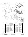
8.16 Sound cabin
17
7
1
3
9
16
12
6
2
4
19
5
18
13
10
20
15
8
14
11
Pos
1
2
Qty.
1
1
Art. no.
1
1
1
1
3
1
1
1
4
1
1
5
6
7
1
1
1
1
1
1
1
1
1
8
9
10
11
12
13
14
15
16
17
18
19
20
34
SPARE
PARTS
1
1 1 1
3 3 3
1 1 1
2 2 2
5 5 5
4 4 4
8 8 8
8 8 8
2 2 2
1 1 1
1 1 1
15 15 15
4 4 4
1-29581
2-29583
2-29584
2-29585
2-29586
2-29587
2-29588
2-29589
2-29590
2-29591
3-29592
2-29593
2-29613
2-29614
2-29615
329655
940032
950555
950533
940261
950557
950556
940076
940054
970218
970148
940213
940257
Description
Granulator CF-810-K
Granulator CF-814-K
Granulator CF-819-K
Cover, left
Cover, front
Cover, front
Cover, front
Cover, rear
Cover, rear
Cover, rear
Door
Door
Door
Holder, rear
Bracket, cover, rear
Border
Border
Border
List
Socket cap screw
Lock, door lock
Hinge
Rivet
Nut, blind rivet
Nut, blind rivet
Socket cap screw M5
Socket cap screw M8
List
List
Socket cap screw M6
Rivet
CF Series Granulators
UGG003/0398
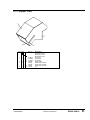
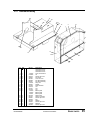
8.17 Enclosure/Body
14
20
1718
19
16
10
2
1
4
6
12
11
21
22
13
15
7
3
5
8
Pos
1
2
3
4
5
6
7
8
9
10
11
12
13
14
15
16
17
18
19
20
21
22
Qty.
1 1 1
1 1 1
10 10 10
12 12 12
2 2 2
12 12 12
6 6 6
1 1 1
2 2 2
1 1 1
1 1 1
1 1 1
1 1 1
1
1
1
2 2 2
2 2 2
4 4 4
4 4 4
4 4 4
14 14 14
2 2 2
2 2 2
UGG003/0398
Art. no.
1-29542
2-29582
940213
940647
991567
950269
950321
4-30274
940027
970195
970218
970141
970148
1-29539
1-29540
1-29541
950148
950147
940051
940024
940155
940037
4-30076
940104
9
Description
Granulator CF-810
Granulator CF-814
Granulator CF-819
Cover, transmission
Lid
Socket cap screw
Torx screw
Lock, door lock
Nut, blind fastening
Nut, blind fastening
Stop, door
Nut M6
Noise absorber
List
List
List
Bottom plate
Bottom plate
Bottom plate
Wheel, fixed
Wheel, foot brake
Socket cap screw
Nut
Washer
Socket cap screw
Distance
Socket cap screw
CF Series Granulators
SPARE
PARTS
35
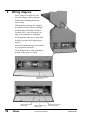
9.
Wiring diagram
Never change or modify the basic
electrical settings of the granulator,
without first obtaining permission
from Conair.
If the granulator settings are changed,
the machine can be seriously damaged.
All Warranties and ConairÕs Product
Liability will be void, if the basic settings of the granulator are changed.
All maintenance and service work must
be done by trained and competent personnel!
Electrical installation must only be done
by a competent electrician!
The distribution box of the granulator is
located on the right, low down.
CF series-K
Motor overload circuit
breaker (F1)
CF series-KUB
Motor overload circuit
breaker (F1)
36
WIRING
Blower overload circuit
breaker (F2)
CF Series Granulators
Conveyor belt overload
circuit breaker (F3)
UGG003/0398
9.1 Current sensing relay
The granulator can be equipped with an optional current sensing relay to control
the feed equipment.
The current sensing relay detects the mill motor current consumption and can
temporarily stop accessories such as conveyors, roller feeders etc to avoid putting
further material into the hopper, when the mill is running under heavy loading.
The relay stops and re-starts accessory equipment automatically, without re-setting.
Relay functions and normal settings:
C
T1 Ð
Start delay, prevents the relay from breaking
on connection (0.1 - 10 sec).
The default start delay is 0.1 seconds.
T2 Ð
Reaction time, prevents the relay from breaking
during temporary high loading (0.1 - 3 sec).
Default reaction time is 3.0 seconds.
A Ð
Hysteresis, adjustable between 5 - 50%
of the set limit.
Default hysteresis is 20 %.
B Ð
Limit value, adjustable between 0 - 100 %.
A
T2
Default setting depends on the current transformer size.
Check the current transformer size and then check the
default setting for this granulator.
C Ð
Relay function, N = normal; I = inverted;
T1
B
Connection
The current sensing relay is connected in series with
the mill motor via a current transformer.
The transformer is connected between M and E1/E2/E3
depending on the secondary current.
(For transformers with transformation to 1 A, this is
connected to E2.)
Default setting for this granulator:
Granulator motor, rated current:
Current transformer:
..............
................................
=
..............
A
/1A
Start delay T1:
0,1 sec.
other value:
....................
Reaction time T2:
3,0 sec.
other value:
....................
Limit values:
%
.......................... = ............................ A
Hysteresis:
%
.......................... = ............................ A
UGG003/0398
CF Series Granulators
WIRING
37
Example
The granulator is equipped with a current sensing relay to control a conveyor.
A motor of 7.5 kW has a rated current of about 15 A.
When this star/delta is started, it pulls about 15 A/
i.e. about 9 A per phase.
Relay setting:
Motor size 15 A/
= 8,7 A per phase
T1 Ð
Start delay setting 0.1 second.
T2 Ð
Reaction time setting 3.0 seconds.
A Ð
Hysteresis 20 %.
B Ð
Limit value 30 %.
C Ð
Relay function N normal.
The current transformer size is 30/1A.
The current transformer is connected to E2 (1 A).
C
A
T1
T2
B
In a current transformer with a transformation ratio of 30/1, the limit value B
should be set to 30 % or 9 A (30 A = 100 %).
The current sensing relay detects the current consumption of the granulator
motor and stops the conveyor, when the granulator motor exceeds 9 A for
3 seconds, to prevent further material from being fed into the hopper.
The relay re-starts the conveyor automatically when the granulator motor consumption has fallen 20 % below 9 A, i.e. to 7 A without a time delay.
38
WIRING
CF Series Granulators
UGG003/0398
10. Layout
A
CF-810 680
CF-814 800
CF-819 920
CF Series, allround hopper ”K”, hopper loader, soundproof
B
B
240
360
480
200
1170
1490
1860
240
50
A
460
900
220
1560
CF Series, allround hopper ”K”, blower F-7 cyclone AX-7,5 with holder/bag holder,
soundproof
320
650
A
CF-810 680
CF-814 800
CF-819 920
240
200
1180
1490
1860
740
B
B
240
360
480
320
A
220
460
1560
470
UGG003/0398
890
CF Series Granulators
LAYOUT
39
CF Series, allround hopper, hopper loader, soundproof
200
240
50
220
A
A
CF-810 680
CF-814 800
CF-819 920
900
1490
1350
1900
B
390
1490
B
240
360
480
CF Series, allround hopper ”K”, hopper loader, non soundproof
200
240
1170
1490
1860
B
50
A
220
890
460
1560
A
CF-810 670
CF-814 790
CF-819 910
40
LAYOUT
B
240
360
480
UGG003/0398
CF Series Granulators
CF Series, allround hopper ”K”, blower F-7 cyclone AX-7,5 with holder/bag holder,
non soundproof
320
650
A
CF-810 670
CF-814 790
CF-819 910
200
240
1170
1490
1860
740
B
B
240
360
480
A
480
460
890
220
1560
CF Series, allround hopper, hopper loader, non soundproof
200
240
1490
1350
1900
B
50
A
A
CF-810 670
CF-814 790
CF-819 910
220
890
1490
B
240
360
480
CF Series Granulators
390
UGG003/0398
LAYOUT
41
CF Series, allround hopper, band conveyor, hopper loader, non soundproof
200
240
1490
1590
1900
B
320
1490
50
390
3730
A
CF-810 670
CF-814 790
CF-819 910
220
A
890
200
B
240
360
480
CF Series, allround hopper, band conveyor, hopper loader, soundproof
200
1590
1490
50
320
1490
1900
B
390
42
220
200
3730
A
CF-810 680
CF-814 800
CF-819 920
A
900
B
240
360
480
LAYOUT
CF Series Granulators
UGG003/0398
CF Series, allround hopper ”KB”, band conveyor, hopper loader, non soundproof
200
1790
50
320
1490
1650
B
860
3730
A
CF-810 670
CF-814 790
CF-819 910
220
A
890
200
B
240
360
480
CF Series, allround hopper ”KB”, band conveyor, blower F-7, cyclone AX-7,5, soundproof
700
640
320
200
1790
1650
320
1490
B
860
3730
A
CF-810 680
CF-814 800
CF-819 920
UGG003/0398
320
900
A
220
200
B
240
360
480
CF Series Granulators
LAYOUT
43
CF Series, profile hopper, non soundproof
240
B
80
1470
1290
1400
80
50
A
900
220
1190
A
CF-810 670
CF-814 790
CF-819 910
44
LAYOUT
B
240
360
480
CF Series Granulators
UGG003/0398
11. Accessories
Overview
The granulator is divided into the following modules:
Page
11.1
Pre-setting of rotating knives, granulator with open cutter ...... 46
11.2
Third fixed knife, removing, installing ...................................... 47
11.3
Band conveyor ............................................................................ 48
11.3.1 Spare parts for the band conveyor .................................. 50
Ordering spare parts
Only use original Conair spare parts when replacing machinery components.
Orders should be sent to the representative in the country where the machine
was purchased.
When ordering spare parts, please specify:
¥
Machine type/designation, on the machine«s rating plate.
¥
Serial number, on the machine«s rating plate.
¥
Part number, from this list of spare parts.
¥
Number of components.
UGG003/0398
CF Series Granulators
ACCESSORIES
45
11.1 Pre-setting of rotating knives, granulator with open cutter
Knives can only be pre-set on granulators with open cutter.
The knives are pre-set on a jig.
The jig is not included when the
granulator is delivered, but is
a very practical accessory.
Setting up the knives
NOTE! The knives must be
sharpened before pre-setting.
When the machine is delivered, the jig is calibrated
against the set screws welded solid in the granulator cutter.
The jig gives the correct clearance of 0.20 - 0.30 mm.
¥
Screw the adjustment screws on a rotating knife in somewhat.
¥
Put knife in the jig, with the edge downwards.
¥
Put an 0.20 mm feeler gauge
between the adjustment screws
and the rear of the jig.
¥
Unscrew the adjustment screws
until the feeler gauge begins to
bind.
¥
The pre-setting is now completed
and the knife can be installed in the cutter.
Installation of pre-set knives.
NOTE! Each time the knives are changed, the
fastening screws must be replaced by new ones.
Install one pair of knives at a time.
46
¥
Clean the knife attachments.
¥
Install one pair of knives
¥
Install the attachment screws with washers loosely.
¥
Adjust the pair of knives against the outer edges of the cutter housing.
NOTE! The knives must butt up against the rings on the outer edges
of the cutter housing.
¥
Make sure that the knives butt up against the rear of the knife attachment.
¥
Tighten the fastening screws, tightening torque 220 Nm.
¥
Re-check that the knife clearance is 0.20 - 0.30 mm.
Check against both the front and rear fixed knives.
¥
Re-check that the knives butt up against the outer edges of the cutter housing.
¥
Install the remaining pairs of knives in the same way.
ACCESSORIES
CF Series Granulators
UGG003/0398
11.2 Third fixed knife
As an optional extra, the granulator can be equipped with a third fixed knife to
increase the efficiency of the granulator.
Open the hopper to install/remove the third fixed knife.
CF series-K, remove the rear guard plate over the motor and open the door.
Removal
1. Undo and remove the screws
(A) which hold the knife.
2. Remove the knife (B).
3. Clean the knife attachments
where the knife was installed.
Installation
1. Install the knife on the knife
attachment.
2. Screw in the socket cap screws
(A), so that the support rule (C)
lightly supports the knife.
B
C
3. Press the knife firmly into the
knife attachment to bed it down.
NOTE! The screws in the rear
of the knife attachment are
bonded in place.
NOTE! The knife has a fixed
position and no adjustment
may be done.
4. Tighten the screws (A), with an
alternating tightening torque to 40 Nm.
A
Sharpening
The third fixed knife is disposable and is changed when necessary.
UGG003/0398
CF Series Granulators
ACCESSORIES
47
11.3 Band conveyor
The band conveyor is designed for transporting plastic waste. The conveyor is
constructed from steelbeam. The frame pieces are assembled with cross sections and screw.
The conveyor can be fitted with a metal-free zone and a metal detector.
Safety
When performing any work with the band conveyor, both the circuit-breaker
and the main circuit-breaker must be ÒOffÓ. Alternatively, the connector must
be pulled out of the power point on the granulatorÕs electrical cabinet!
The conveyor is designed for plastic waste. Do not use the conveyor for tasks
other than it is intended for.
Nobody should be on the conveyor or step on it during operation.
If the conveyor has stopped due to an error, or if the emergency stop has been
pressed, it must not be re-started until the cause has been established and the
appropriate action has been taken.
Mobile conveyors must always be transported in a lowered position.
Warning! When using the conveyor belt with carriers: Be careful not to let
the carriers catch your foot, arm, or article of clothing.
Installation
When installing, adjust so that the band conveyor is balanced diagonally.
If the floor of the installation site is very uneven, it should be made even
before installation.
Electrical connection
The band conveyor should be connected up by an authorised electrician.
Connect the cables to the electrical cabinet according to the markings and the
granulatorÕs electrical scheme (see chapter 9). Alternatively, connect the band
conveyor to the electrical cabinet with the connector.
Switch on the main circuit-breaker on the electrical cabinet. Press the start button and check that the belt moves in the right direction.
If the belt moves in the wrong direction.
Shift the two phases in the connection to the contactor for the band conveyor
in the electrical cabinet. Alternatively, shift the two phases in the connection to
the connector.
Starting
When the band conveyor is started for the first time, the beltÕs position on the
rollers should be checked. The belt must not move obliquely.
If the belt moves obliquely.
When the belt moves obliquely. Screw one adjusting screw at a time. Only
screw a 1/4 turn. Wait and let the belt move for a few minutes. Check, adjust,
48
ACCESSORIES
CF Series Granulators
UGG003/0398
wait, and check again until the belt moves straight.
Belt tension.
The conveyor beltÕs length has 1% tolerance. Never tension the beltÕs adjusting screws with a greater tightening torque than 5 Nm.
Maintenance
During all maintenance work on the band conveyor, both the circuit-breaker
and the main circuit-breaker must be ÒOffÓ. Alternatively, the connector must
be pulled out of the power point!
Regularly check the conveyor beltÕs wear and its position on the rollers. The
belt must not move obliquely! Adjust as necessary according to the instructions under ÒStarting - If the belt moves obliquelyÓ (see previous chapter).
Clean the belt using a light cleaning agent. Do not use any sharp objects,
strong cleaning agents or chemicals which can damage the belt.
Trouble-shooting
If the band conveyor does not start
The conveyor belt motor has an overload circuit
breaker, F3, in the distribution cabinet, which trips
if you jam or overload the conveyor belt.
This is indicated in the window (A) which then
shows an Ò0Ó.
A
B
To reset, press the ÒresetÓ button (B).
Also check the wiring diagram in chapter 9, additions
and modifications can occur.
UGG003/0398
CF Series Granulators
ACCESSORIES
49
11.3.1 Spare parts for the band conveyor
31
34
30
6
37
29
28
36
5
32
16
23
25
22
17
19
35
33
1
11
9
7
8
20
15
10
18
21
14
13
27
4
26
24
2
3
12
Pos
1
Qty.
1
1
1
2
1
1
1
3
1
1
4
5
6
7
8
9
1
1
1
1
1
1
1
1
1
1
1
1
1
1
1
1
1
1
10
11
2
1
2
1
2
1
12
13
14
15
16
17
2 2
2 2
4 4
6 6
10 10
4 4
50
1
2
2
4
6
10
4
Art. no.
3-030648
3-030650
3-030652
2-030649
2-030651
2-030653
2-030692
2-030680
2-022657
2-030693
2-030681
2-023510
4-020496
2-022654
2-023508
2-023956
2-023957
2-030694
2-030687
2-022658
4-007550
2-030695
2-030688
2-022659
950412
950411
940306
940044
940057
940005
Description
Band conveyor B200 CC2700
Band conveyor B350 CC2700
Band conveyor B450 CC2700
Band conveyor
Band conveyor
Band conveyor
Bracket wheel
Bracket wheel
Bracket wheel
Bracket wheel
Bracket wheel
Bracket wheel
Shaft
Bracket upper left
Fäste upper right
Leg left
Leg right
Bracket wheel rear
Bracket wheel rear
Bracket wheel rear
Slewing brack
Stirrup leg
Stirrup leg
Stirrup leg
Wheel fixed
Wheel turnable
Screw
Screw
Screw
Socketscrew
ACCESSORIES
Pos Qty.
18
2 2 2
19
4 4 4
20
6 6 6
21
4 4 4
22
4 4 4
23 22 22 22
24
2 2 2
25
2 2 2
26
1 1 1
Art. no.
940059
940015
940317
940155
940031
940162
950061
950267
911006
Description
Nut
Nut
Nut
Washer
Washer
Washer
Retaining ring SGA
Sealing end
Connector 6-pol
Pos
Art. no.
3-030689
3-030690
3-030691
2-030648
2-030650
2-030652
2-022341
2-022342
2-010792
910589
910964
911214
910963
940057
940240
940162
911006
950271
Description
Band conveyor B200 CC2700 MD200P
Band conveyor B350 CC2700 MD350P
Band conveyor B450 CC2700 MD450P
Band conveyor for metal detector
Band conveyor for metal detector
Band conveyor for metal detector
Holder control
Holder warning
Pole warning
Warning lamp
Metal detector MD200
Metal detector MD350
Metal detector MD450
Screw
Screw
Washer
Connector 6-pol
Nut blind rivet
27
Qty.
1
1
28
29
30
31
32
1
1
1
1
1
1
1
1
1
1
1
1
1
1
1
33
34
35
36
37
5
8
4
1
2
5
8
4
1
2
1
5
8
4
1
2
CF Series Granulators
UGG003/0398
12. Transport and storage
General
The machine should be transported by trained personnel.
The machine is delivered packed in protective plastic foil, fixed to a pallet
with straps.
Unpacking and checking
¥
Check that the machine has not been damaged during transport.
NOTE! Report any damage to the forwarding agent.
¥
Do not unpack the machine before it has been transported to where it is
going to be used.
¥
Check with the delivery note that the delivery is complete.
Lifting and transport to place of use
The machine weighs incl. packaging,
approx. 470 - 600 kg.
Space requirements,
see Layout, chapter 10
The machine can be lifted
and handled with a fork-lift
truck.
The lower part of the machine
has two openings on the righthand side which accommodate
a fork-lift truck.
Drive in a fork-lift truck as far
as possible (until the bends in
the forks touch the machine),
and then lift the machine.
Positioning in place of use
See Installation, chapter 5.
Storage
The machine is packed for transport to the place where it is to be used.
On delivery it is protected with Castrol DWX 22 anti-rust oil.
Long-term storage/Conservation
¥
Store the machine in a room with a stable, dry temperature.
¥
Treat the unpainted surfaces of the machine with rust preventer, such as
Castrol DWX 22. DWX 22 will protect the machine up to 12 months.
Alternatively, DWX 160 will provide protection for 24 - 36 months.
UGG003/0398
CF Series Granulators
TRANSPORT/STORAGE
51
Conair has made the largest investment in customer support in
the plastics industry. Our service experts are available to help
with any problem you might have installing and operating
your equipment. Your Conair sales representative also can
help analyze the nature of your problem, assuring that it did
not result from misapplication or improper use.
WE’RE HERE
TO HELP
To contact Customer Service personnel, call:
HOW TO
CONTACT
CUSTOMER
SERVICE
From outside the United States, call: 814-437-6861
You can commission Conair service personnel to provide onsite service by contacting the Customer Service Department.
Standard rates include an on-site hourly rate, with a one-day
minimum plus expenses.
If you do have a problem, please complete the
following checklist before calling Conair:
❒ Make sure you have all model, serial and parts list
numbers for your particular equipment. Service
personnel will need this information to assist you.
BEFORE YOU
CALL ...
❒ Make sure power is supplied to the equipment.
❒ Make sure that all connectors and wires within
and between control systems and related
components have been installed correctly.
❒ Check the troubleshooting guide of this manual
for a solution.
❒ Thoroughly examine the instruction manual(s)
for associated equipment, especially controls.
Each manual may have its own troubleshooting
guide to help you.
❒ Check that the equipment has been operated as
described in this manual.
Additional manuals and
prints for your Conair
equipment may be
ordered through the
Customer Service or
Parts Departments for a
nominal fee.
❒ Check accompanying schematic drawings for
information on special considerations.
IMS0002/0296
SERVICE INFORMATION
APPENDIX A-1
EQUIPMENT
GUARANTEE
Conair guarantees the machinery and equipment on this order,
for a period as defined in the quotation from date of shipment,
against defects in material and workmanship under the normal
use and service for which it was recommended (except for
parts that are typically replaced after normal usage, such as
filters, liner plates, etc.). Conair’s guarantee is limited to
replacing, at our option, the part or parts determined by us to
be defective after examination. The customer assumes the cost
of transportation of the part or parts to and from the factory.
PERFORMANCE
WARRANTY
Conair warrants that this equipment will perform at or above
the ratings stated in specific quotations covering the equipment or as detailed in engineering specifications, provided the
equipment is applied, installed, operated and maintained in the
recommended manner as outlined in our quotation or specifications.
Should performance not meet warranted levels, Conair at its
discretion will exercise one of the following options:
● Inspect the equipment and perform alterations or adjustments to satisfy performance claims. (Charges for such
inspections and corrections will be waived unless failure
to meet warranty is due to misapplication, improper
installation, poor maintenance practices or improper operation.)
● Replace the original equipment with other Conair equipment that will meet original performance claims at no
extra cost to the customer.
● Refund the invoiced cost to the customer. Credit is subject to prior notice by the customer at which time a
Return Goods Authorization Number (RGA) will be
issued by Conair’s Service Department. Returned equipment must be well crated and in proper operating condition, including all parts. Returns must be prepaid.
Purchaser must notify Conair in writing of any claim and provide a customer receipt and other evidence that a claim is
being made.
WARRANTY
LIMITATIONS
APPENDIX A-2
Except for the Equipment Guarantee and Performance
Warranty stated above, Conair disclaims all other warranties with respect to the equipment, express or implied,
arising by operation of law, course of dealing, usage of
trade or otherwise, including but not limited to the
implied warranties of merchantability and fitness for a
particular purpose.
WARRANTY INFORMATION
IMS0003/0796