1
I
1
1
\L
return to
esc
Camera Servrce Center. 619 W 54th Street, New York, NY 10019. Tel. (212) 757 0906
I
II
I
1
!
i·
!I
I
-
i
i
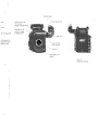
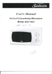
ARRIFLEX 535B
i:
!
j:
;
INSTRUCTION MANUAL
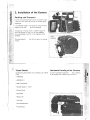
Bubble level
urrei
Adjustment knob
for manual
image compensation
icator)
20 m magazine
Release key for
manual image
compensation
~.
/
~ Fddioo odi,,'meo'
/
Finder arm
_ocking grip on
Tlagazine cover
[take-up side)
PL-mount
~Adjustable
mirror
shutter
Cover In
magazine opening
y:
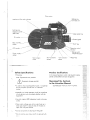
Regulator knob,
illuminated-frame finder
Eyepiece
Lever for conrrast filter
/
/
Socket for
heated eyecup
/ / / ; R,I'm, I",cfocf"d"
/
'c,ce'
Magazine alsplay
(electronic film stock indicator)
Locking grip on
magazine cover
(toke-up side)
"PHASE"-key~'
Sliding switch /
"DISPLAY LOCK"
I
!
Display
Grip system
Release key
/for finder arm
Mechanical film stack indicator
~.
//
Locking grip,
magazine cover~
(feed side)
~/
RU socket -
Video optical tap
_
Dovetail-guide
"RUN"-key
~Operation control
CCU-socket --------------
Power supply
socket
Main camero
switch
I
24 V accessory
sockets
~icator
\
12 V accessory
socket
Sliding switch
"NORM-PSjCCU"
".'''PROG''-key
_.----
---.-
- ..
_~_._-----~~
Safety Specifications
Product Specifications
• Warnings
In the case of enquiries or when ordering parts please
advise camero number and type designation.
Note: Operational error possible!
ill
Equipment damage possible!
• !n order to ensure optimal performance, it is essential
that you acquaint yourself with this instruction
manual.
• Assembly and initial operation should be carried out
only by persons who are already familiar with the
equipment!
• Use only original ARRI replacement parts and acces
sories!
• Clean optic surfaces only with an optic brush or a
clean optic cloth! In cases of solid dirt moisten an
optic cloth with pure alcohol.
• Do not use solvents in cleaning the film gate!
• Do not unscrew any screws which are secured with
paint!
Meaning of the Symbols
in the Instruction Manual
signifies objects which are shown in photos.
.....
,;:,
..'"
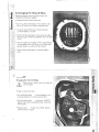
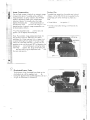
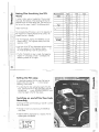
Magazine Display
Mechanical Film Stack Indicator
Removing Exposed Film
Contents
c
J!
c
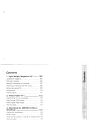
1. General Description of the
ARRIFLEX 5358
5
2. Installation of the Camera
6
21
22
23
5. Camera Body
o
u
Packing and Transport
Tripod Heads
Horizontal leveling of the Camera
Bridge Plate BP·5
lens Support
Grip System
Shoulder-Set S-l
3. Power Supply
Mirror Shutter
Exchanging the Ground Glass
6
Film Gate......................
7
Pitch Adjustment
7
8
10 6. Optics
1 1
lenses............................
13
Viewfinder System
24
24
26
27
30
34
..
14
7. Camera Operation
Battery NC 24/7 R
Mains Unit NG 12/24 R
Charger NCl 24 R
Power Supply of Accessories
Changing the Camera Fuse
15
15
16
16
17
4. Mcgczines ..•............•........•............•••.... 18
loading the Magazine
34
35
18
42
Main Camera Switch
42
Running the Camera
43
Warning Displays
44
Inching
45
Displaying and Setting Operational Parameters .. 45
Overview of the Display Modes
46
Overview of the Display Symbols
47
Film Counter
48
Displaying the Angle of the Mirror Shutter
50
2
.
"
Setting Frame Rates
Displaying the Power Supply Voltage
Timecade
Switching on and off the Warning Signal for
Asynchronus Running
8. Video-Assist-System
Mounting
Mounting
Mounting
Adjusting
the
the
the
the
Video-Assist-System
Video Camera
Anti-Flicker Processor AFP-2
Video Optic
9. Accessories
Work light Wl-3
Heated Eye Cup
Remote Control Unit RU-1
Remote on/off Switch RS-4
External Synchronization Unit ESU-l
Camera Control Unit CCU-1
50
52
53
55
56
57
58
58
60
62
Setting the Film Loop
SWitching on and off the Time Code Recording
Time Code Input........
Time Code Output
Time Code and the
External Synchronization Unit ESU-1
Time Code Buffer Battery
Overiview of the Display Indications in
Time Code Operation
77
77
78
79
80
80
81
11. Maintenance ....•.•..•••..•.......................•. 82
Camera
Magazine
62 Appendix
63
64
Troubleshooting
65
Technical Data
65
Order Numbers
66
82
86
88
88
92
94
Index ......••••...•••....••••................................ 96
10. Time Code
Time Code Frame Rates
Mounting the Time Code Modul
Setting Film Sensitivity (the TCS-Value)
74
74
75
76
,
i
c
.o
...
...e
c
U
:)
""0
,4
...
--------.....,..",,.....,,,
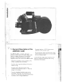
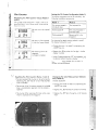
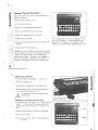
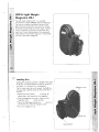
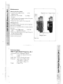
1. General Description of the
ARRIFLEX 5358
The ARRIFLEX 535B is a compact, light-weight
production camera. Due to the modular design of the
camera, its range of functions can be individually
expanded. The following functions are already
integrated into the basic version of the ARRIFLEX 535B.
·c
The optical tap for a 1/2" CCD video camera is
integrated into the viewfinder system.
The versatile grip system is connected directly to the
camera body and can be used as a carrying handle
or as an occessory holder.
.
...ou
::::a..
:""0
...e'c,
-
A comprehensive range of optical, mechanicai and
electronic accessories further extends the working
possibilities of the camera.
..- j
"
..... 1
j
Operational parameters can be set directly on the
camera, accessories are not necessary.
The frame rates range from 3-60 fps for forward or
reverse running.
The open sector of the mirror shutter can be
0
0
mechanically adiusted from 180 to 11 when the
camera is not running.
The newly developed viewfinder system can be
exchanged without tools. The viewfinder can be
swung on two axes and can be used on both sides of
the camera with full image compensation.
5
c
2. Installation of the Camera
.-o
.gj
=
.2
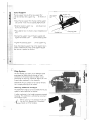
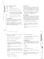
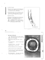
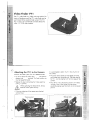
Packing and Transport
I
-c'"
In order to prevent damage to the mirror 5hutter, either
a len5 or a len5 cavity cap mU5t be on the len5 mount
receptacle.
If the ARRIFLEX 535B i5 tran5ported or 5tored without a
magazine the cover
5houid be attached.
Tran5porting or 5toring empty or loaded magazine5
5hould be carried out only with the loop protector
to avoid damage to the film or the magazine throat
a»embly.
The loop protector
handle.
..
can abo be u5ed
05
Loop
protector
,
a carrying
\
\
\
6
~----------
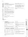
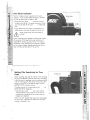
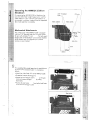
Tripod Heads
Horizontal Leveling of the Camera
The following tripod head5 are 5uitable for U5e with the
A built-in fluore5cent bubble level
allow5 leveling
of the camera even under poor light condition>.
535B:
• ARRIHEAD
• ARRIHEAD C
.C
o
]1
-.2
-'"
'C,
• ARRI Fluid-Head5
• Sachtler Studio 7, 150 H
• Mitchell-Head
• Moy-Head
• Ronford F7
--"
--
I
I
I
• Hot-Head
I
• Cam-Remote-Head
I
• Worall-Head
I
I
I
I
i'
I
I
7
,.-'11
I1
1
..-"
c
o
'.-
-.2
'It
-
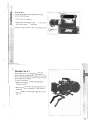
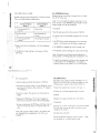
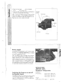
Bridge Plate BP-5
The bridge plate facilitates balancing of the camero on
the tripod. The bridge plate consists of the base plate
and a pair of support
, the sliding upper plate
rods
. Pairs of support rods are available in the
lengths 240 mm and 440 mm.
Bose plate
\
"
C
Super 35-Format
For filming with the Super 35 format the lens receptacle
and the upper plate of the bridge plate must be
adjusted. This ensures that the accessories also fit
exactly to the optical centre which is altered in the
Super 35 format,
Sliding upper plate
Support rods
The position currently in use, Standard or Super 35, is
indicated by two markers on the sliding upper plate,
The bridge plate can be adiusted for the Super 35
format as follows:
• Remove the three screws
0
• Turn the rail 180 and refasten in this position.
8
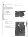
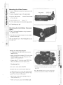
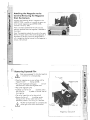
Attaching the Bridge Plate to the Camera
• Fasten the sliding upper plate
with the two slit
screws
to the camero base. The cylindrical pins
(twist prevention) must glide into the holes.
• Then screw the bose plate
onto the wedge plate
on the tripod and lock onto the tripod head.
• Slide the camero with the upper plate into the
dovetail-guide of the bose plate until the springloaded stop pin
snaps back audibly.
• Slide the support rods into the guides and clamp.
• Equip with he desired accessories for balancing on
the camera. Then loosen the clamping lever
and
by sliding the camera on the base plate find the opti
mal position. Then retighten the clamping lever
Removing the Camera from the Tripod
• Before removing the camero make sure that all cables
are disconnected and that the eyepiece leveling rod
is detached.
• For fast removal of the camero from the tripod loosen
the clamping lever
, push in the stop pin
and
then pull the camera with the upper plate
from
the base plate.
9
c
lens Support
o
.•
1
-]
-'"
o
The lens support consists of the lens support LS-7
and the individual lens support ring
for the lens in
use.
Lens support
LS-7
• Mount the lens support from the top onto the support
rods and let it click shut by applying slight pressure.
'C
• Slide the relevant support ring
do not yet clamp tight.
.~
1
I1
onto the lens but
• Then slide the lens into the lens mount receptacle and
lock.
Clamping lever
• Connect the support ring with the lens support and
and the clamping lever
tighten the knurled screw
• Tighten the clamping screw
on the support ring.
Note: Mounting the support ring on the relevant lens is
usually carried out only once as the support ring can
then remain in position on the lens .
.10
--~.
i
j
, l
Grip System
The new flexible grip system on the ARRIFLEX 535B
guarantees the highest stability through its fixed
connection to the camera body and offers various
possibilities for attaching accessories. Eight 3/8" inner
threads allow attachment in four directions.
Additionally the grip system can be used as the base
for a hanging mounting of the camera.
Attaching Additional Handgrips
C I1
O.
.';0I''
==i
O!
·1
-
"']
c,
The additional handgrips can be screwed onto the grip
system in various positions as required.
\I
A safety mechanism in the handgrip prevents automatic
loosening. This mechanism is activated by screwing in
the handgrips tightly.
I
,....
/1 \
.L.:..:;;.
Before screwing in the handgrips make sure
that the 3/8" threaded bolt is completely
screwed out of the handgrip.
I
J
\ ..
..c
.-o
o
.2'It
-
I:
Grip System
In order to minimize camera height the entire grip
system can be removed.
Grip system
I
• First remove the magazine.
• Loosen both the hexagon screws
in he struts and
backwards.
pull the grip system
Attaching the grip system is done in the opposite order.
12
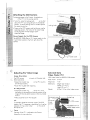
Shoulder Set S-l
The shoulder set S-l was designed for takes that
require frequent changes of the camera position. It
allows quick transferring of the camera from the tripod
onto the operator's shoulder without having to remove
the optical accessories.
• Remove the camera from the tripod (see under
"Bridge Plate BPS').
• Slide the shoulder set into the dovetail-guide on the
bridge plate (locks automatically in stop position).
• Plug the cable for the ON/OFF trigger key into the
RS-socket.
13
1
I
1
S
I
_)--13
1
•.P
ower
uppy
"8:!
,"
Battery NC 24/7 R
The camera is designed for use with a nominal voltage
:) 1 of 24 V DC. The acceptable voltage range is from 20
.\
~ ! to 32 V DC. The power supply cable should be
'" j ~connected to the "BAT"-socket on the camera.
G)
.~
·0
D.
For power supply on the ARRIFLEX 535B
- the battery NC 24/7 Rand
- the mains unit NG 12/24 R
are available.
Do not open the batteries!
Charge batteries only with the ARRI chargers!
Do not bypass the fuse or temperature switch!
Do not heat NC-batteries!
Do not short-circuit NC-batteries!
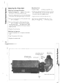
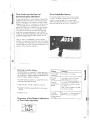
Mains Unit
NG 12/24 R
Battery Charger
NCL 24 R
Battery NC 24/7 R
Mains Unit NG 12/24 R
The battery NC 24/7 R has a capacity of 7 amp
hours.
Use of the mains unit is recommended for filming in the
studio and when using electronic accessories with a
high power consumption.
• Ensure that the main switch on the camera is off.
I
•
• First check that the correct mains voltage is set.
• Plug the -battery cable KC 20 or the coiled battery
cable KC 29 into the "BAT"-socket on the camera
and into the battery-socket.
• Ensure that the main switch on the camera is off.
• Set the voltage switch on the mains unit to 24 V.
• Plug the battery cable KC 20 or the coiled battery
cable KC 29 into the "BAT"-socket on the camera
and into the 24 V-socket on the mains unit.
/---
\.
i
i
Ii
?
15
Charger NCL 24 R
Power Supply of Accessories
With this charger all ARRI 24 V batteries can be
charged.
Power Supply of 24 V Accessories
• First check whether the correct mains voltage is set on
the charger.
Power Supply of 12 V Accessories
• Connect the charger to the power supply .
• Plug the charger cable into the battery socket.
• Press the start button.
LSD
Meaning
yellow
discharging (lA)
red
charging
green
charger connected to the mains
16:j
. .)
,:
l
Changing the Camera Fuse
Main fuse:
15 A
The fuse and the replacement fuse are located under
the screw-in cover
• Using a coin unscrew the screw-in cover
• Remove the defective fuse with the special forceps for
changing the ground glass.
~l
a.
Q.t
~l
''''1
Ii.
Q)'
~j
a.\
• Take the replacement fuse out of the screw-in cover
and put in place with the special forceps.
• Screw in the screw-in cover.
I
17
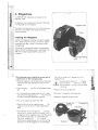
4. Magazines
,A.II ARRIFLEX 535 magazines can be used on the
ARRIFLEX 535B.
An electronic and a mechanical indicator of film stock
are integrated into the magazine.
M~gazine cover
The take-up and feed motors as well as the monitoring
electronics are located in the magazine and are
maintenance-free.
Loading the Magazine
Loading the magazine should be practised in daylight
with a piece of test film until you are familiar with all
movements and able to work in a darkroom or film
changing bag.
Cutting the film through the middle of the perforation
holes simplifies the loading process considerably. The
ARRI Film Cutting Gauge simplifies cutting in the
darkroom.
18
..
i
The following work should be carried out in
a darkroom or film changing bag
• Place the magazine with the feed side up (right side;
mechanical film stock indicator face up) on a flat
surface.
• Press the button
grip
up.
and flip the flag-hinged locking
=!
Push the film through until it emerges out of the
magazine throat.
~
I !\
•
CI
·M I
Ensure that the threading aid
is flipped
back into position
. Otherwise it rotates
) when the camera is running which can cause
a loud noise.
at
ml
g'
~I
• Place the film roll on the feed shaft
\
• Turn the locking key counter-clockwise until it stops
and remove he magazine cover
. Place this with
its interior face down beside the magazine.
• Flip down the hinged clip on the feed shaft
• Replace the magazine cover and lock.
• Flip up the hinged clip on the feed shaft
Threading aidl
• Place the film roll on the magazine cover
. The
magazine cover serves as a height-compensation
base.
• Then slide the film into the opening
. Continue
sliding the film without catching or bending it until it
emerges out of the magazine throat. If the film cannot
be pushed through eaSily, use the rhreading aid
Flip up the threading aid
, turn it counter
clockwise and simultaneously push the film until the
sprockets can be felt engaging the film perforation.
I
Feed shaft
/
I
.
I
I
i
I
I
!
Opening/
I
I!
19
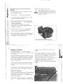
The follov.ring v.rork can be carried out in
• Replace the magazine cover and lock.
daylight.
• Lay the magazine on the feed side (electronic film
stock indicator facing up).
• Press the button
LG.
After loading the magazine it is essential to
set the magazine display. The set values are
automatically read by the camera when rhe
magazine is attached.
and flip up the locking grip
• Turn the locking grip counter-clockwise until it stops
and remove the magazine cover
• Slide the head of the film into the lower magazine
throat assembly opening
, until it emerges inside
the take-up compartment.
Note: The length of the loop is at this stage
unimportant. It is set once the magazine has been
attached to the camera.
• Place the head of the film in the expandable film
core, clamp it in place and wind the film roll
clockwise approximately one turn.
• Ensure that the film is running at a right angle to the
take-up shaft. Otherwise the film roll can rub against
the magazine cover and cause noise.
I
Lower magazine throat assembly opening
20
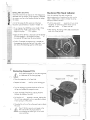
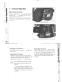
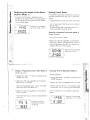
Magazine Display
The magazine display
indicates in mode 1
(counter) the remaining amount of unexposed film stock
in the magazine.
Note: This indicator only serves as a counter, i.e. the
indicated value is calculated based on the set quantity
of film and is therefore only as accurate as the given
setting. When running the camera backwards the
counter runs backwards.
In mode 2 (Time Code Sensitivity) the film sensitivity
value for the correct time code recording can be set
and read.
indicator, the second SET-key from the left must be
pressed.
By simultaneous depressing of the left and right SET
keys the maximum film length for the magazine in use
is set, e.g. on a 120 m magazine" 120", or ,.,393" if
the unit of measurement is set at feet. The unit of
measurement - meters or feet - is automatically set when
the magazine is attached to the camera. If, for
example, the camera display is set to "feet", the
magazine will also count in feet when attached to the
camera.
A buffer battery in the magazine enables saving and
storing the values even if the magazine is detached.
Setting Film Quantity
Note: Film quantity can also be set while the magazine
is detached from the camera. If the magazine is
attached, the camera must be in the Standby position
when setting the values.
Each SET-key stands for a position in the magazine
display
. In order for example to change the "tens"
21
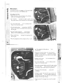
Setting Film Sensitivity
Mechanical Film Stock indicator
Note: Film sensitivity can also be set if the magazine is
detached From the camera. If the magazine is attached
the camera must be in the Standby position for setting
the values.
With the mechanical film stock indicator the
approximate quantity of remaining film stock can be
read in meters or feet in order to transfer this to the
electronic film stock indicator.
A list of the values for film sensitivity of the most
frequently used emulsions is located in chapter 10.
• To set, depress the MODE-key once. Mode 2 (Ti me
Code Sensitivity, TCS) is now chosen. In the
magazine display
"TCS" appears.
upwards until you notice
• Push the sliding switch
resistance. The remaining quantity of film can be
in meters and feet.
read from the scale
• After releasing, the sliding switch slides automatically
back into its initial position.
• Hold one of the SET-keys depressed until the desired
TCS-value appears in the magazine display
. In
this mode all SET-keys have the same function.
• If within 5 seconds no programming is carried out,
the magazine display springs back into mode 1 and
now shows the remaining quantity of film stock.
'• •
I
i
i
'
•
ill
uti
.-N'l
Removing Exposed Film
I\
t
-/
G).
Only remove exposed film from the magazine
in a darkroom or film changing bag.
Locking grip
Magazine cover
• Place the magazine on the feed side.
• Depress the button
\
and flip up the locking grip
0,
Button
"
C»j
II
. -
Lever
• Loosen the head of the film by pressing the lever
towards the middle of the shaft.
I
upwards to remove, holding the
• Pull the film roll
film roll from underneath as far as possible to prevent
it from caving in in the center.
'
&!
"';
I
I
• Turn the locking grip counter-clockwise as far as it
will go, and remove the magazine cover
• Place the film roll on a flat surface and insert a plastic
film core.
'
ell'
j
.,
Fi\~ roll
I
Even if the film core only sits loosely in the
film roll, the film roll should under no
circumstances be pulled tight as this could
cause scratches.
1
I
~3
I
.J
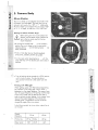
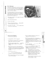
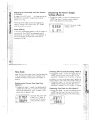
5. Camera Body
Mirror Shutter
The mirror shutter can be adiusted mechanically while
the camera is disconnected. The open sector can be
adjusted continuously from 180° to 11 0 Additionally
0
the mirror shutter can be locked within the range of 180
to 1SO in 15°-steps, as well as at 172,8° and 144°.
Setting the Mirror Shutter Angle
&
I
•
Before setting the mirror shutter remove the
camera from the power supplyl Remove the
lens or the lens cavity cap from the lens
mount receptacle.
on the movement,
• By turning the knurled knob
position the mirror shutter so that the open sector
adjusting device
and the locking device
are
easily accessible.
• With a 2 mm Allen key turn the locking device
towards the "LOOSE" position until it stops.
• Turn the open sector adjusting device
with the
same Allen key until the desired open sector angle is
reached.
"1
I
• Turn the locking device towards the "LOCK" position
until this locks in place. The adjusting device
may possibly have to be turned slightly back and
forth.
...... ,'!
"€1
.0 .i
I
IGj
O' !i
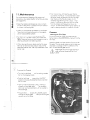
Filming with HMI Light
I.i
When lighting scenes with HMI/CID·discharge lamps,
pay attention to the pulsing light intensity which is
dependent on the supply frequency. The camera frame
rate, the supply frequency of the lighting and the angle
of the mirror shutter must all relate to each other in
order to achieve constant lighting. As the camera frame
rate and the supply frequency of the lighting are
normally given, compensation must be carried out
through the angle of the mirror shutter.
Ei
a»
81
I
j
In the following table the mirror shutter angle to be set
can be seen.
I
Supply
frequency
Frame rate
Open sector
50 Hz
I
60 Hz
25 fps
24 fps
24 fps
180°
172,8°
144°
I,'
2S
------------- ------
----...-"
•
.
•
I
>.
Exchanging the Ground Glass
o
Before exchanging the ground glass remove the
camera from the power supply!
'"'0
sa
2
~
E
a
u
• Remove the lens/the lens cavity cap.
• By turning the knurled knob on the movement, twist
the mirror shutter out of the lens receptacle area.
"1
• Using the special forceps, pull the ground glass
out of the holder by its catch
• Check that the ground glass to be inserted as well as
the ground glass frame are completely clean and free
of dust.
• Push the chosen ground glass with the special forceps
into the holder as far as it will go. A ball catch fixes
the ground glass in exactly the right position.
• Check that the ground glass is correctly locked in
place .
. .. .J
'/
1
1
/'-..:.......-'--'----------------_._-
i
Film Gate
Changing the Format Masks
&•
.I
When filming, a format mask must always be
in the film gate.
To take out the format mask
~
.>.,
'"
;-Uf
·0 . .,
~:
al
raj
G)'!
el
.al
u
j
• Turn the knurled knob
on the movement until its
marking matches that on the movement block.
\
• Push the locking lever
towards the "UNLOCK"
position and swing the movement block away from
the film gate.
towards the "LOOSE" position
• Press the lever
and flip out the film gate
27
• Pull
the filter holder
sideways out of the film
\-=--.
gate.
\
• Press the format mask
lightly on its side flap
towards the film gate and then pull this out sideways
too.
Filter
foils
.
Filter holder \
Film gate
'
\
\
\
\
'~.4
F~rmat mask .. \ • \
,.~~\
To insert a format mask
'\.. . ~:::.,>
• Check that the film gate frame and the surface are
absolutely clean.
"~'"
...... ,
~, ~~
• Push the new format mask sideways into the film gate
• Pull the film gate lightly towards the movement block
and push in the filter holder
• Press the lever
towards the "LOOSE" position
and push the film gate back into its correct position.
• Ensure that the lever
'~
,-
;'
/
-c.' _
........
'1";
':\7 '
swings back completely.
Inserting Filters into the Film Gate
Filter foils such as gelatine filters can be inserted into
the filter holder.
• Turn the knurled knob
until its markings match
those on the movement block.
• Push the locking lever
towards the "UNLOCK"
position and swing the movement block away from
the film gate.
towards the "LOOSE" position
• Press the lever
and flip out the film gate
• Pull the filter holder
gate.
sideways out of the film
• Slightly expand the filter holder and insert the filter
foil
. Cut off iutting edges.
• Push in the filter holder
• Press the lever
towards the "LOOSE" position
and push the film gate into its correct position.
• Ensure that the lever
swings back completely.
29 .
~
o
rA
Movement
The ARRIFLEX 535B is equipped with the same reliable
seven-link-movement as the ARRIFLEX 535.
e
Threading the Film
E
• Open the camera door and remove the protective
cover from the magazine opening.
G)
o
u
• Turn the lever
towards the "OPEN" position. The
film guide rockers will be removed from the sprockets
• Turn the knurled knob
until its markings match
those on the movement block.
• Push the locking lever
towards the "UNLOCK"
position and swing the movement block away from
the film gate.
approximately
• Push the loaded magazine
halfway into the dovetail-guide on the camera.
• Place the film loop
the film gate.
between the movement and
• Push the magazine into the camera as far as it will
.. ~
t;:'·~.~ ~
~") .;-<
;':'~'-
go. The magazine locking device
automatically.
.
;'"
locks
• Snap the film guide rockers onto the sprockets by
carefully turning the lever
towards the "CLOSED"
position, ensuring that the sprockets correctly engage
the film perforation.
• Position the film loop
film loop markings
by hand between the two
until its markings match
• Turn the knurled knob
those on the movement block.
• Swing the movement block onto the film gate, turning
the locking lever
downwards and ensuring that
the transport claws slide into the film perforation.
• Ensure that the locking lever
completely.
swings back
• Setting the upper and lower film loops is done with
on the sprockets. Depress the
the knurled discs
knurled discs and then turn these until the film loop is
between the film loop markings
• Check correct film transport by turning the knurled
knob
31
~
Pitch Adjustment
"o
The camera is delivered with a transport claw pitch of
4,74 mm [short pitch). With this basic setting negative
film stock, for which the perforation hale distance is
within the tolerance range, is transported steadily and
quietly by the claw movement.
£d
g
I.
G)
E
g'
u
'1
,I
For optimal quietness of running the movement can be
fi nely adapted to the various film types or emulsion
numbers with the pitch adjustment. It is recommended
before beginning filming to establish the optimal pitch
setting for the film material in use.
l
j
!
• Place approx. 60 m film in the magazine. See under
"Threading the Film".
• Leave the camera door open.
• Switch on the camera.
• Slowly turn the pitch adjustment
until the quietest setting is reached.
back and forth
• The figures on the scale
serve to enable finding
of previously chosen settings.
32
Removing the Magazine
• Firstly open the camera door.
If unexposed film is still in the magazine:
• Swing back the movement block and snap the film
guide rockers away from the sprockets.
• Press the magazine locking device
and pull the
magazine approx. halfway out of the camera
housing.
• Remove the film loop from the area between the
movement and the film gate, then pull the magazine
completely out of the camera body, ensuring that the
film does not get caught on the movement or on the
sprockets.
If the entire film has been used.
• If the entire film is on the take-up side it is not
necessary to swing back the movement block.
• The film guide rockers should however be snapped
away from the sprockets.
• Press the magazine locking device and pull the
magazine out of the camera beey.
Note: In the swung back position :he movement is
uncoupled from the drive system Both the movement
and the drive system can now 'Je turned
independently of each other. Before swinging in the
movement ensure that the coupiing device is correctly
positioned.
~
.-0
o
ca
"0
...
Q).
-E
81
• Turn the knurled knob
until :ts markings match
those on the movement block.
• Depress the "PHASE"-key to incn the drive system.
The electronic control system tnen checks
automatically that the coupling device on the drive
side will stop in the correct position.
If the movement is swung in while not
connected to a power suo ply, the correct
position of the drive sice coupling half IS not
ensured. If the movement meets with
resistance while swinging in, the coupling
engagement must be reSTored by slowly
turning one of the knurled discs.
Never activate the movement locking device
while the camera is runrl;ng!
33
.
...~
Q.
o
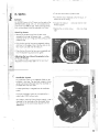
6. Optics
lenses
All ARRIFLEX lenses with a PL-mount can be used on the
ARRIFLEX 535B. Lenses with a 41 mm standard or ba
. : yonet mount can not be used. Heavy and long lenses,
such as zoom-lenses, must be supported at all times.
• To do this remove the six cylinder screws
• Turn the lens mount receptacle so that the figure .. 2"
stands next to the marking
• Unscrew the index pin
thread opposite .
and screw into he inner
• Replace the six cylinder screws
tight.
and screw these
Attaching Lenses
• Remove the protective cap from the lens mount
counter
receptacle by turning the bayonet ring
clockwise as far as it will go and then pulling out the
protective cap.
• Push the lens into the lens mount receptacle without
catching it at the edges. One of the four slots on the
lens mount must slide over the index pin
• Press the lens flat onto the lens mount receptacle and
tvvist the bayonet ring clockwise to tighten.
Adjusting the Lens Mount Receptacle to the
Super 35-Format
For filming with the Super 35 format the lens mount
receptacle must be turned 180°.
34
Viewfinder System
The viewfinder system on the ARRIFLEX 535B can be
swivelled in tvvo axes. The viewfinder image is always
upright and correct left-to-right when the viewfinder is
swivelled within the main axes.
A video optical tap is integrated into the viewfinder
system.
The entire viewfinder system can be replaced by a
video finder (100%) without tools.
With slide-in masks the filming format currently in use is
displayed in the viewfinder as an illuminated frame.
The intensity can be continuously adjusted with the
ARRIGLOW.
..
1
\
I
"I
J
I,
'"
a
o
.~
Adjusting the Eyepiece
.1
Removing the Eyepiece
• Turn the knurled ring
position,
towards the "OPEN"
• Remove the eyepiece
Attaching the Eyepiece
• Ensure that the knurled ring is turned to the "OPEN"
position,
• Attach the eyepiece to the viewfinder,
• Turn the knurled ring
position,
towards the JOCK"
Adjusting the Diopter
The diopter compensation is fitted with a scale
1 to 12, Position ,,6" is nominal focus,
of
36
Adjusting the Viewfinder
Hexagon
screw
Turning the Eyepiece
The eyepiece can be rotated 360° around the finder
arm, The eyepiece is held in position by friction.
Friction is set by the knurled knob
Swivelling the Finder Arm
The finder arm can be swivelled approx, 270°, On the
left side of the camera the finder arm locks into the
horizontal position, After depressing the release key
the finder arm can be swivelled out of this posi
tion, Now the finder arm is held in the set position by
friction. If necessary, friction can be set with the hexa
gon screw
Knurled
knob
Extending the Finder Arm
The finder arm can be telescoped continuously by
approx, 50 mm.
• To do this loosen the knurled ring
finder arm
to the desired length,
and pull the
,j
Find~r arm
1I
Knurled ring
1
I
• Retighten the knurled ring,
37
I
• VI
,
u
.•0
'j
o
Image Compensation
Contrast Filter
The viewfinder system is fitted with an automatic image
compensation device. To enable setting a different
image orientation in certain situations, the viewfinder
system is additionally fitted with a manual image
adjustment device. Ta manually adiust the image,
depress the locking key
and simultaneously turn
the adjustment knob
until the finder image is in the
desired position. Automatic image compensation can
be re-activated as follows:
To enable better recognition of possible stray light and
reflexes, a contrast filter [ND 6) can be pivoted into the
optical beam path of the viewfinder by means of a
lever
• Swivel the lever
into position .,1".
• To enable unrestricted viewing swivel the lever into
position ,,0".
• Turn the adjustment knob
until this locks into
position. Do not depress the locking key.
Note: The automatic image compensation locks into
two positions which are 180° aport. This allows
attachment of a finder extension with an image which
is correct left-to-right and upright. If the finder image
without the viewfinder extension is inverted, the com
pensation prism must be turned 180° by depressing the
and simultaneously turning the adiust
locking key
approx. 30°. Let go of the locking key
ment knob
and continue turning the adjustment knob
until
th is locks into position.
Illuminated-Frame Finder
< /
The brightness of the illuminated-frame finder can be
continuously set with the regulator knob
. By
turning the regulator knob counter-clockwise as far as it
will go, the illumination is switched off.
39
.
..o
.'u-"
Illuminated-Frame Mask
• Remove the viewfinder system [see below) .
0.
• Open rhe lid
on the underside of the finder
turret
by turning the lock
clocKwise until the
lid springs up.
• Grasping the illuminated-frame mask
special forceps, pull it out.
with the
• Grasp the new illuminated-frame mask with the
special forceps and push in with the notch towards
the rear until this locks noticeably in position.
• Push down the lid
and lock.
• Replace the finder system (see opposite).
40
r:
..
.'"
".-U
,,",,-..
Exchanging the Finder System
Finder System
0.
oj
Before removing the finder system the viewfinder
should be brought back to its normal position.
6•
I
I
i
When operating the release lever, hold the
finder system securely!
• Depress the safety catch
lever
upwards.
j
'1
~
i
and pull the release
• Tip the finder system forwards. Let go of the release
and remove the finder system by pulling
lever
upwards.
Attaching the Finder System
• Check that the release lever is completely in its
original position. If the finder sys;em is detached or
not completely locked in place, 'ne release lever
stands at a slight angle.
I
on the gUide pins,
• Place the finder system
tipping it slightly forwards.
.....
1
• Swing the finder system downwards until it locks in
position.
41
----------
,
L-- .
..
\ co
.-
o
1.1
Q)
0.
o
o
I.
Q)
e
1
7. Camera Operation
Main Camera Switch
The main camera switch
is on the underside of the
. The recessed location prevents
electronic cover
unintentional switching on or off
In the "ON" position the camera is in Standby. In the
"OFF" position, the camera is cut off from the power
supply and the display gives no indications.
0
U
I
i.
Electronic cover
Main camero sWitch
I
I
42
-- - --- -
-_.'.- '--_.
__
._---------...,--~,'
\
-.1
'i
;
j
Running the Camera
Switching off the Camera
An ON/OFF key (RUN) is located
of the camera.
• Again depress the RUN key
briefly. While the
camera is running down the operation control indica
tor glows red. The mirror shutter automaticaily stops
in a position that enables an unrestricted view
through the viewfinder. On reaching this position the
operation control indicator flashes green before
going out.
on both sides
Switching on the Camera
• Depress the RUN key briefly. While the camera is
running up, the operation control indicator glows red.
Once the set frame rate has been reached, the
operation control indicator
switches to green.
If the operation control indicator glows red
while in Standby, the camera is not ready
and cannot be switched on (see warning
displays).
c
....Ol
.0
._
. _ JI'
Q)
,o.:j
0'1
ol
el
0'
.1.. 1
Q)l
u
It is possible to operate the ARRIFLEX 535B
with the movement block swung back. In this
case the operation control indicator blinks red
in Standby and red/green while the camera
is running.
43
c
o
-.;:
e
Q)
Q.
o
e
Q)
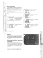
Warning Displays
In order to enable it to recognize operational errors,
the ARRIFLEX 535B is fitted with various sensors. The
corresponding warning displays can be seen on the
camera display until the error is rectified. During this
time the camera cannot be used and the operation
contra! incicator glows red.
On the camera display operational errors are shown as
follows:
E
!ft
rl .1 .1 rt
i
L.I L.I L.' L.I
,
1 tps
I
I
'-
;ft
o
u
!
nil
bat
n .1 .1 .1
filter ,
nnn
U U L.I
_
bat
n
filter
I
i
ft
nnnnfilter) Movement block not locked
U U L.l L.I
in position. At the rear stop
I'
.1
n n
I
U L.I U bat I
I.: : '= =======::::::J
fps
the display will blink and
the camera can be run
without the movement.
U L.I L.I
.t .1
(ft
i
I
n
L.' L.I _ L.I
U
I fps
t
Film guice rockers no~
locked in ?osition
filter:
Film I'am in the lower film
,loop area
U L.I L.I
fps
i
Magazine not completeley
attached
IIr,nn
L.l L.I L.I L.I
bat
':=C======..J
ft
Ir
l
IfPs
n n n n
U
U L.I U
n
n n
filter
1 Film jam in the upper film
I
I
loop area
U_L.IL.lbat,
ft
1
I fps
I
n
U
.1
illilter
L.' L.1
11.1.,
II
L.I L.I L.I L.l
Magazine test. If there is no
error this indication disap
pears after approx. 2
seconds.
bat
·44
Inching
Inching can be started by depressing the "Phase" key
while the camera is in Standby. If the "Phase"-key is
only lightly tapped, the mirror shutter opens respec
tively closes.
Displaying and Setting Operational
Parameters
The currently set operational perameters on the
ARRIFLEX 535B are displayed on the camera display in
various modes. The desired mode is selected via the
"MODE"·key. In each mode the corresponding opera
tional parameters can be set using the "SEL"- and
"SET"-keys.
To prevent an unintentional alteration of the opera
tional perameters the "SEL"- and "SET"·keys can by
locked using the sliding switch "DISPLAY LOCK".
45
,.-----"
C
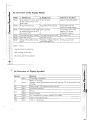
An Overview of the Display Modes
.
Mode
1. Displcy Line
Mode 1
Total exposed film counter (m/ft) Frame rate (fps))
or take counter [m/ft) or mirror
shutter angle
Standard frame rate selection
Mode 2
Programmed frame rate
Programmed frome rate
(forwards/reverse) selection
Mode 3
Total exposed film counter (m/ft) Power supply (V)
or remaining film stock (m/ft) or
take counter m/ft)
Unit of measurement (m/ft)
selection. Film counter
configuration selection
Mode 4
Time code time (hours, minutess)
Time code time (seconds, fps))
Time code on/off
Mode 5
Time code user bits
Time code user bits
Mode 6
Setting of the audible warning
signal
TCS-value or voltage of the time
code buffer battery (V)
.o
a
~
G)
a.
o
I ~a
J.
1U
i,
!
'
2. Displcy Line
Adjustment Possibility
Programmed frame rate (fps)
Warnign signal on/off
Mode 1 is shown:
when the camera is switched on.
after operating the RUN key.
30 seconds after the last operation .
.~
46
An Overview of Display Symbols
Symbol
Mecning
glows
TC-recording is switched on
blinks
"RUN": No recording
"Standby": the last synchronization was over 8 hours ago (TC can be recorded for test
purposes)
bat
glows
Battery voltage < 20V (camera cannot be started)
asy
glows
asynchronous operation
glows
film end
blinks
film end warning
fps
blinks
ESU is attached and no relevant frequency is available
jam
glows
film jam in the upper film loop
filter
glows
a filter is in the film gate
TC
end
47
c
.o
o
Setting the Film Counter Configuration (Mode 3)
Film Counter
...
..
Displaying the Film Counter Values (Modes
and 3)
G)
a.
o
e
Film counter values are shown in modes 1 and 3, As
described below, two of three counter '/olues can be
shown at a time:
8 =-81:'
.0
Q)
~
':E
-0
). U
••
U
I
m
1
I
l
2 -1
1
~
38.0
LI
2'-1
the amount of film exposed
in individucl scenes (takes)
1 •
,1
J
the total amount of exposed
film
m
I-
••
LI
.no
I U
,
-,
2
the remaining film in the
magazine
(= magazine display)
1
-'
,
Mode 3
Film amount exposed in
individual takes
Total exposed film
Total exposed film
Film amount exposed in
individual takes
Total exposed film
Remaining film in the
magazine
By choosing the desired counting method in mode 3
the display configuration is set.
• Depress the "SEL"-key twice; the first digit in the first
display line blinks_
• Within 3 seconds depress the "SET"-key repeatedly until
the desired method of counting is displayed in mode 3_
The corresponding film counter value in mode 1 is
thereby automatically altered_
1
48
Mode 1
• Change from mode 1 to mode 3 by depressing the
"MODE",key twice.
"
,~,
The display configuration can be set individually. The
following combinations are possible:
Ij
,
1
--
Resetting the Film Counter (Modes 1 and 3)
• The total exposed film counter can be set to zero by
depressing the "SET"-key (for at least three seconds)
while in Standby.
• The counter of the film amount exposed in individual
takes is automatically reset each iime the camera is
restarted_
• The counter of the remaining film takes on the value
which is displayed on the magazine.
-
--_ .. _ - -
Changing the Unit of Measurement (Meters/
Feet, Mode 3)
Standby Operation
• Change from mode 1 to mode 3 by depressing the
"MODE"-key twice.
• Depress the "SEL"-key once (the symbol m/ft blinks).
• Depress the "SET"-key to change the unit of measure,
mente
4Q
..
c
o
.-
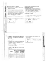
Displaying the Angle of the Mirror
Shutter (Mode 1)
a
• As long as the Phase-key is depressed while in
Standby the set angle of the mirror shutter appears in
the first display line. During this period the camera
runs at inching speed.
~
G)
a.
·0
e
<
G)
E
a
.U
,
) fps
1
Example: The set angle of
the mirror shutter is 144°.
--1'-1.0
25.00
~
Setting Frame Rates
The ARRIFLEX 535B offers the possibility to set frame
rates and to store these for later use. It is pOSSible to
choose
• a standard frame rate (24, 25, 29,97 and 30 fps)
• and a freely programmed frame rate (in increments
of 0,001 fps).
The desired frame rate is activated with the "PS"·
switch on the right side of the camera.
Choosing a Standard Frame Rate (Mode 1)
.1
Standby Operation.
• The camera must be in mode 1.
• Depress the "SEL"·key repeatedly until the desired
frame rate is chosen. Within 3 seconds, confirm this
choice by depressing the "SET".key, otherwise rhe
program returns to its initial setting.
nnL'8
U U -'.0
Example: The set standard
frame rate is 24 fps.
2 '-to 0
- i
I
so
1
_._._-_ ...
.i
~-------------
Setting a Programmed Frame Rate (Mode 2)
Choosing R.everse Operation (Mode 2)
Standby Operation
;
Standby Operation
• Change from mode 1 to mode 2 by depressing the
"MODE"-key once.
• Depress the "SEL".key repeatedly until the desired
digit to be set is activated.
.......o
c'
• Change from mode 1 to mode 2 by depressing the
"MODE"·key once.
• Depress the "SEL".key repeatedly until "CD" blinks.
-g..-'
G)J
A..
01
gl1
-~
Note: The thousandth-position is shown in the right.
hand corner of the first display line.
• Depress the "SET"·key repeatedly until the desired
value is reached.
Note: The frame rate can only be chosen between 3
and 60 fps.
r
!IIps
,.....
,
I\.
PS 5
•03
='
• La'. La
I
I
,\
Example: The set programmed frame rate is
18.325 fps.
• Confirm with the "SET"·key On the display before
the indicator "PS", a minus sign will be displayed.
Note: The frame rate can be altered as described
above.
Ir
lIPS
-115-5
I_
c'
. G)
\
·-E
. g .:
c~l;
Example: The set reverse
frame rate is -21,325 fps.
!
I
:'32
I
I
. ,I
i
,J
1
Sl
c
.o
Changing the Frame Rate while the Camera
is Running
...
a
By means of the "PS"-switch
the frame rate can be
changed from standard to programmed while the
camera is running.
..0)'
'
Q.
o
Displaying the Power Supply
Voltage (Mode 3)
• Change from mode 1 to mode 3 by depressing the
"MODE"-key twice. The power supply voltage is
shown in the second line of the display.
Fine-tuning of the frame rate can be carried out by
means of the keys "SEL" (slower) and "SET" (faster)
while the camera is running.
e
I Example: The power supply
voltage ist 24 V.
Q)
E
a
,.U
Phase Shifting
To film from quartz-locked monitors while the camera is
running, hold the "PHASE"-key depressed until the
horizontal bar is no longer visible in the viewfinder. In
the camera display the frame rate will be seen to
increase by 0,2 fps.
j
\
S2
...... . t
(
\
Time Code
Switching off Time Code Recording (Mode 4)
Note: The time code modes 4 and 5 are activated only
if the TC-module is installed. If the TC-module is not
installed the display jumps directly from mode 3 to
mode 6.
• Change from mode 1 to mode 4 by depressing the
"MODE"-key three times. Hold the "SET"-key de
pressed for 3 seconds. The "TC"-symbol will go out.
Displaying the Current Time Code Time
(Mode 4)
• Change from mode 1 to mode 4 by depressing the
"MODE"-key three times. In the first line time code
time will be displayed as "hours: minutes", in the
second line as "seconds: fps".
2
'·u
n .,.n
h:min
TC
sec:f
U
JL'2 U
::.
o· -,
Example: The current time
code time is 7 hours, 2
minutes and 36 seconds,
the frame rate is 24 fps.
Switching on Time Code Recording (Mode 4)
• Change from mode 1 to mode 4 by depressing the
"MODE"-key three times. Hold the "SET"-key de
pressed for 3 seconds. The "TC-symbol will appear .
Displaying Time Code User Sits (Mode 5)
• Change from mode 1 to mode 5 by depressing the
"MODE"-key four times. The user bits will be dis
played in the first and second lines of the display.
TC
us
2 3: I I '
5.• g' .Q
=.
'-11_1
I
2
J
4
--
S3
....
c
Displaying reS-Values (Mode 6)
.-o
o
• Change from mode 1 to mode 6 by depressing the
"MODE"-key five times.
Q)
• The TCS-value (time code sensitivity; the recording
intensity for time code, which is dependent on the
film stock used) will be displayed in the second line
of the display with values of 1 to 9. An indication of
the TCS-values is only possible if the magazine is
attached. Otherwise there is no indication.
Q.
o
f!Q)l
E
o
u
Note: A list with the TCS-values for the most commonly
used film stocks is given in Chapter 10, Time Code.
LS
S
Example: The set TCS value
11
is ,,7
-.
Displaying the Voltage of the Time Code
Buffer Battery (Mode 6)
• Change from mode 1 to mode 6 by depressing e
"MODE"-key five times. If no TC-module is Installed
mode 6 will come immediately after mode 3, i.e. if
no TC-module is installed it is only necessary to
depress the "MODE"-key three Imes.
• Depress the "SEL"-key once.
• The TC-battery voltage is displayed in the second line
of the display. If the voltage is < 7V, the battery
should be replaced.
••
U
•
,._---"---------------- --
Example: The TC·baitery
voltage is 9.3V.
LS-
'-'3
::1._
Switching on and off the Warning
Signal for Asynchronous Running
(Mode 6)
Standby Operation
• Change from mode 1 to mode 6 by depressing the
"MODE"-key five times (or three times if the TC
module is not installed) .
• With the "MODE"-key confirm the selection and
return to mode 1.
LS
[ S
.,
Example: The warning tone
is on when starting and off
when stopping the camera.
•
• By depressing the "SEL"-key twice, the setting for the
warning signal is activated .
• With the "SEr.key, select one
possibilities:
Display
.~
,~
.
of the four following
~one I
~one
Warning
Warning
on startmg
on stoppmg
the camera I the camera
LS
off
off
LS -
on
off
LS
off
on
LS -
on
on
I
I
I
I
,
:'it;
··S
..."'I
>-!
.CD
8. Video-Assist-System
The video-assist-system provides a high quality, nearly
flickerfree monitor image for PAL or NTSC. The video
assist-system consists of the video set, the 1/2" color
video camera CCD 2-FR and the anti-flicker processor
AFP-2 .
.'" .
.....enl
.
.-
.
'"
'"
•
<C
. 0
CD
"'''V
co,>
The brightness of the video image is automatically
adapted to the given lighting conditions. This balancing
can also be carried out manually. The white balance is
designed for standard values for interior and outside
filming. The integrated technology for image-storing
enables reproduction of a stored image or the alterna
tion between the real and the stored image in order
for example to align the camera to an earlier scene.
0
When using several video cameras the video-assist-system
can also be synchronized by an external video signal.
Changing from a color to a black/white CCD-camera
is simple and calls for no subsequent adjustment. The
ARRIFLEX 535B is fitted in the standard version with a
beamsplitter which reflects 20% of the viewfinder beam
to the video camera. A 50% beamsplitter can be
installed subsequently.
56'
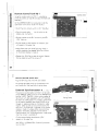
Mounting the Video-Assist-System
Mounting the Video Optic
• Firstly unscrew the cover on the finder turret.
Vide~ optic
• Pull the cover off the bayonet-mount on the video
optic.
• Place the bayonet-lock on the video optic into the
recess on the finder system
• Turn the video optic
locks in place.
counter-elockwise until it
Note: In the locked position, the video optic is angled
upwards by 5°.
Removing the Video Optic
• Pull back the ring marked "RELEASE"
and turn
clockwise as far as it will go.
the video optic
• Pull off the video optic.
51
I__.__ ~
f
:
I
1
\'
.j
Mounting the Video Camera
• Unscrew the protective cover from the C-mount on the
video optic.
Video camera
• Unscrew the protective cap on the video camera.
• Screw the video camera
on the video optic.
• Loosen the locking ring
onto the C-mount thread
approx. 15°.
• Turn the video camera into the correct angle position.
• Pull the locking ri ng tight.
Mounting the Anti-Flicker Processor
AfP-2
• Screw in the dovetail-adapter on the grip system
the ARRIFLEX 535B.
of
• Then slide the anti-flicker processor into the dovetail
guide and screw tight.
Note: Like the video optic, the dovetail-guide must also
be angled by 5°
1
1
.,.II
:·58
,
.
{
j
\
I
Wiring the Video-Assist-System
E'
',,2
• It is imperative to turn off the main switch on the
ARRIFLEX 535B.
...--
>-1
U)\
• Attach the anti-flicker processor AFP-2 via the socket
MOVIE CAMERA to one of the RS-sockets of the
camera with the cable KC 37.
• I,
utI
.ut
ut
• Plug the cable KC 34 into the socket VIDEO CAM
ERA on the AFP-2 and into the video camera.
<C
• The video signal for the monitor is possible from two
sockets on the AFP-2:
'Q)
Mini monitor: socket MINI MONITOR
o•
."
>(
• Switch on the video-assist-system using the switch on
the AFP-2.
Standard video monitor: BNC-socket VIDEO OUT
The BNC-socket "VD in" on ~he video camera CCD 2
FR is used in synchronizing with an external video
signal. Do not use as a video output!
'-
• Set the code switch on the underside of the anti
flicker processor to ,,9".
• Switch on ~he main switch of the ARRIFLEX 535B.
I
ut'
Note: The anti-flicker function can be optimally ad
justed as required with the slit screw "PHASE ADJ"
Adjusting Focus
E
!
Adiusting the Video Optic
-
• Loosen the locking ring
approx. 1Y (as seen in
the direction of filming, counter-elockwise).
• Loosen the lock
on the focus adjustment ring.
Adjusting the Image Orientation
'"
~
U').
I
&It
,
--"':
lit'
~l
I
1
O~
Q)!
.,,'
>
I
II
• Adiust the angle position by turning the CCD-eamera,
at the same time checking the image on the monitor.
• Tighten the lock on the focus adiusrment -ing
• Set the horizontal position with he adiustment screw
SW 1,3 marked x.
Note: The focus range off the video optic can be
altered with the gear ring
on the video camera.
• Set the vertical position with the adjustment screw
SW 1,3 marked y, ensuring that on loosening
the adjustment screw
the image follows. Other
wise press the CCD-camera at the screw-on position
slightly upwards.
• Retig hten the locki ng ri ng.
Adjusting the Aperture
.1 •
"1
1
1"l
• Check focus through the monitor and aa[ust with the
focus adiustment ring. For more accurate Judgement,
the aperture can be completely opened.
Loosen the aperture lock in the aperture adiustment
knob
• Align the aperture to the monitor.
• Retighten the aperture lock.
60
-":'~~I
I
(:
I
E
G)
..
Lock on focus
adjusment ring
/
I.
j
i
",'
~l
--"',
'"'"
<I:
•
I
,
"I
Adjustment screw
for vertical position
LockinQ ring
~
oG)
">
Aperture ad[ustment knob
\
Gear
ring
./
61
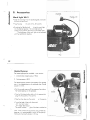
9. Accessories
Lamp head
Flexible shaft
Work Light WL-3
\
• Slide the work light into the dovetail-guide and fasten
with the knurled screw.
• Plug the plug
into one of the "RS"-sockets.
bring the work light
• By setting the flexible shaft
into the desired position. The work light can be
turned on and off with the switch on the lamp head
. The brightness of the work light can be adjusted
with the mechanical aperture.
62
Heated Eyecup
The heated eyecups are available in two versions.
.
1. Anatomically shaped eyecup: HE-3A
2.
. .~
Folding eyecup: HE-3F
The heated eyecup prevents the eyepiece from misting
over in low temperatures as for example when filming
outside in winter.
• Pull the normal eyecup off the eyepiece, then place
the heated eyecup on the eyepiece.
• Plug the fully detachable cable with the appropriate
plug into the socket on the camera
• Plug the other plug into the socket
on the eyecup.
a To set the level of heat with the switch
"LO". low heat output
"HI": higher heat output.
The control indicator
glows if the heat is switched on.
Note: If the camera and accessories are powered by
batteries, it is recommended to switch off the eyecup
heating during lengthy breaks in filming.
63
Remote Control Unit RU-l
.-'"G)a.
o
'"'"
u
Q)
'"
<C'
Control cable
Using the remote control unit RU-l it is possible to
switch the camera on and off and adiust the frame rate
externally.
-"f
\~
,_
,
On the ARRIFlEX 5358 it is not possible to alter the
open sector of the mirror shutter with the RU-l .
,
• Switch the main camera switch to "ON" (Standby).
.j
into the socket on the
• Plug the control cable
camera and into the RU-l .
• Set the switches on the RU-l so tnat only the lED
"VSU" lights up.
• On the display on the camera, the indication "SU"
will appear in the upper line.
• Adiust frame rate with the left adjusting wheel; in
standby operation the selected frame rate is shown
on the camera display in mode 2.
• Depress the "RUN"-key to start the camera. Depress
this key again to switch the camera off
~!
I
64
" " - - - - - - - - - - - - - - - - - - ----
o
Remote ON/OFF Switch RS·4
Plug the RS-4 plug into one of the "RS"-sockets.
The remote ON/OFF switch can be attached to the
pan handle of a fluid head with the sping clamp
External Synchronization Unit E5U-l
The external synchronization unit ESU-l can be used
on the ARRIFlEX 535B as well as on the ARRIFLEX 535
and the 16SR 3. The ESU·] allows synchronization of
the camera with other equipment such as TV monitors.
By means of a BNC-socket it is possible to synchronize
on an external standard video signal (50/60 Hz) or
through an inductive pickup on a computer or video
monitor. Other sources can be synchronized via the
Mel-input. The frame rate is indicated on the camera
display in mode 2. A phase shifter and a pilot tone
generator have been integrated into the external
synchronization unit. The synchronization is also stored
when the camera is switched off.
Spring' clamp
-,
On the camera display the indication "ESU"
appears in the upper line.
See TECHN. INFORMATION "External Synchroniza
tion Unit ESU-l "
65 .
~
Camera Control Unit CCU-l
.-'"G)
The camero control unit CCU·] enables control of the
following functions:
L.
0
''""
u
«'"
• Switching the camera on or off.
Q,)
, • Choosing the frame rate.
,
. ,'
i1
1
I
I
l,
1
i
• Checking all set operational parameters.
• Entry of programmed frame rate changes.
• Display and operation of the film counter.
• Setting of warning signals.
I
"'.
I
I
1
• Displaying and setting of TC-time (time code) and TC
user bits.
J
• Displaying of the set TC-sensitivity.
unit is limited to approx. 5 hours, the display illumina·
tion switches off approx. 10 seconds after the last
operation when it is being run on batteries, and the
camera control unit itself switches off after approx. 5 min.
I
,
'~c
•..
·'1
1
.i
I
1
Setting TC-time and TC-user bits can only be carried out
via the camera control unit or through external synchro
nization. The camera control unit is supplied with
power by the camera. If the camera is not plugged in,
the camera control unit will be fed by the internal
batteries. As the battery the life of the camera control
1
I
~
I.,
66 j
.j
Replacing the Batteries
• Open the battery compartment
with a coin.
• Pullout the battery pack.
• Use batteries as designated on the battery pack.
• Insert the battery pack into the camera control unit
and close the battery compartment.
.~ . Pay attention to the correct polarity of the
battery pack!
ill
Battery compartment
Plugging in the Camera Control Unit
• Plug the cable KC 24 [2,4m) or KC 30 (20m) into the
on the side of the camera control unit,
socket
pressing the slide on the plug in the direction of the
plug.
• Plug the cable into the CCU·socket on the camera.
• Switch on the camera.
• Switch on the camera control unit with the red key
on the side.
, Socket
67
Functions in all Menus
"',
Key
Key
Function
..
.
o
The Main Menu
G)'
'"
'"
u
G)
~
RUN
switches the camera on or
SEND
sends the chosen values to the camera.
When the camera contfol unit is switched on the main
menu appears on the display. It enables access to the
sub-menus and shows the speed currently set on the ca
mera. It also shows whether the camera is switched off
(OFFLINE), in Standby (STANDBY) or is running (RUN).
HELP
shows the help text for the activated menu.
Cannot be used in the input mode. The help
text can be left by depressing the ENTER-key.
• Select the deSired menu using keys 1,3,5.6,7 or 8.
The displayed menus SHUTIER (2) and FORMAT (4)
have no function on the ARRIFLEX 535B
EXIT
ends input or leaves the activated menu.
The SPEED Menu
off.
switches display illumination on or off.
Error Readings
In the case of functional errors on the camera, the
display on the camera control unit will show an error
reading in the upper right-hand corner.
With the SPEED menu any desired frame rate within the
range of 3 to 60 fps in increments of 0.001 Fps can be
set exactly. The frame rate can be altered :n Standby as
well as while the camera is running. In bOTh upper lines
of the CCU the frame rates currently set on the camera
control unit and on the camera are displayed.
• Switch the sliding switch on the camera to PS/CCU.
In the case of operational errors, an error reading will
appear and then disappear the next ~ime a key is
depressed. Simultaneously an acoustic signal will be
heard. This can however be turned off.
• Using keys 1 to 5 select one of the listed standard
speeds - the chosen frame rate is displayed in the
uppermost line.
• Transfer the chosen value to the camera with the
SEND-key.
68
Alternatively any desired frame rate within the accept
able range can be selected:
• Switch the camera to mode 2.
• Switch the sliding switch on the camera to PS/CCU.
• To carry out fine-tuning: increase speed with key Fl,
decrease speed with key F2.
• Depress key 8 [VAR) in the SPEED menu.
• Leave fine-tuning with the EXIT-key.
• Enter the desired frame rate.
The REMOTE Menu
• If not all positions after the decimal point were
entered, finish the input with the ENTER-key - the
selected frame rate is displayed in the uppermost line
on the CCU.
In the REMOTE menu the camera control unit displays
the same information as the camera. The keys F1 to F3
take on the meaning of the operating elements on the
camera:
Fl
• Transfer the chosen value to the camera with the
SEND-key.
All selected frame rates within the acceptable range of
3 to 60 fps can be increased or decreased in incre
ments of 0.001 fps in order to carry out a fine-tuning of
the speed.
,
• Switch the sliding switch on the camera to PS/CCU.
"_."
• Pre-select the Frame rate.
'-.::'
..
~
PHASE key
F2 MODE key
F3 SET key [RESET on the CCU)
In the lower line on the CCU display the Key functions
are displayed.
Operating the camera in the REMOTE menu is carried
out parallel to setting with the corresponaing keys on
the camera.
• Depress key 9 in the SPEED menu.
69
The TIME CODE Menu
In the TIME CODE menu the most recently set values on
the camera control unit for time code, as well as all
user bits, are displayed and can be reset.
Changing Time Code Time:
. ,'.'
. ...
.:~
~
• Depress key 1 - "TIMECODE" is displayed against a
dark background.
• Depress the ENTER-key - the camero control unit is
ready for input of the new user bits.
• Enter all 8 user bits with figures 0-9 or letters A-F - the
new user bits will be displayed. input is ended
automatically after the eigth figure. If input is inter
rupted by depressing the ENTER-~ey, all unfilled
positions will be filled with zeros.
• Transfer the new user bits to the camero with the
SEND-key.
• Depress the ENTER-key - the camero control unit is
ready for input of the new TC-time.
• Enter all 6 positions within the acceptable range of
00:00:00 to 23:59:59 - the new TC-time is dis
played. Input is ended automatically after the sixth
digit. If input is interrupted by depressing the ENTER
key, all unfilled positions will be filled with zeros.
• Transfer the new TC-time to the camera with the
SEND-key.
Changing Time Code User Bits:
• Depress key 2 - "USERBITS" is displayed against a
dark background.
The OPTIONS Menu
LENGTH-UNIT
The OPTIONS menu allows access to the sub-menus
ASYNC-MODE, LENGTH UNIT, END WARNING and
COUNTER DISPLAY MODE.
Enables switching the film counter from meters to feet
and back again.
ASYNC-MODE
• Select meters with key 1 or feer with key 2 - the
selected unit of measurement is displayed against a
dark background.
Enables switching the asynchronous warning signal on
and off. There are four possibilities available:
• Transfer the chosen setting to the camera with the
SEND-key.
• With the keys 1 to 4 select the desired mode
END WARNING
Warning tone on
starting the camera
Warnting tone on
stopping the camera
1
off
on
2
on
off
3
on
on
4
off
off
• Select the desired setting with the corresponding key.
Enables setting the amount of film remaining when the
camera displays a warning of nearing film end.
• Depress the ENTER-key.
• Enter the desired remaining film amount (0-99 in
meters or feet, depending on the unit of measurement
chosen on the camera).
Note: The set value is automaticaily taken on by the
camera after the second figure has been entered.
• Transfer the chosen setting to the camera with the
SEND-key.
71
.
The PROGRAM Menu
COUNTER DISPLAY MODE
.-'"
Q)
Enables changing the configuration on the film counter.
There are three possible combinations:
o
'"'"
u
G)
Camera-Display
Mode 1
.(
Camera-Display
Mode 3
1
total exposed film
counter
take counter
2
take counter
total exposed film
counter
3
total exposed film
counter
Enables setting and storing of programs for the altera
tion of the frame rate.
Note: It is not possible to program adjustments to the
mirror shutter on the ARRIFLEX 5358. Possibly entered
shutter angles will not be transferred .
To program:
• Set the sliding switch on the camera to PSjCCU
remaining film counter
• Select the desired combination with the correspond
ing key.
• Transfer the chosen setting to the camera with the
SEND-key.
• Activate one of the available storage areas with keys
1 - 6.
• The FETCH.key places the program which has been
stored in the camera into the chosen storage area.
• The DELETE-key deletes the chosen storage area.
• The EDIT·key allows entering new values with the keys.
Note: Alterations to the frame rate are defined by a
starting speed, a finishing speed and an adjustment time.
• Transfer the program from the activated storage area
to the camera with the SEND-key. If a program is
already stored on the camera, this will be replaced .
• j
72
p-',
"
Running programs:
The INFO Menu
• Set the sliding switch on the camera to PSjCCU.
The INFO menu allows access ~o the menu [uncons
STATUS and COUNTER, as well as switching Qn and
off the acoustic signal on the camera control :.JnlT.
• Activate the program mode with the PROG-key on the
right side of the camera [the indication "Pr" appears
in the display).
• Select the desired menu function wirh keys 1-2
• Switch on or off the acoustic signal with key J.
• Start the camera. The camera runs at the starting
speed.
• Depress the PROG-key. The camera changes its
frame rate in the given time to the finishing speed.
.
'"
.
CI,)
o
'"
Cl,)j
'"
~J
«i
1
STATUS
\
Displays the values currently set on the camera
I
COUNTER
- By again depressing the PROG-key the frame rate will
return to the starting value in the same amount of
time.
Note: The program itself is stored in the camera and
can therefore be activated even if the CCU is not
plugged in.
Displays the current CQunter status of the total exposed
film and take counters as well as the power SUpplY
voltage to the camera
SOUND CCU ON/OFF
Switch the acoustic signal on or off with key .:1. 'Nhen
first switched on, a control signal sounds.
73
Q)
""0
01
..,t
Q»l
.5
i
~I
10.Time Code
Time Code Frame Rates
In modern post-production time code (TC) is finding
increased application. The precise correlation of the
film, sound and video recordings has been made
possible through the use of equipment with time code
capability.
Recording time code is only possible at the following
forwards frame rates:
The ARRIFLEX 535B is equipped for recording time
code onto film. To do this, simply fit the TC-recording
module in place of the film recognition module.
Time code is optically exposed onto the film in compli
ance with SMPTE regulations RP 135 and RP 136,
Format Type C.
Frame rate
Te-Display
24,000 fps
24
25,000 fps
25
29,970 fps
29
30,000 fps
30
23,976 fps
23
At speeds 29,970 fps and 23,976 fps the time code is
counted to comply with NTSC video in the "Nondrop
Frame" mode. The time in the "Nondrop-Frame" mode
runs of exactly 0,1 % slower than real time .
. -',
. 74
Mounting the Time Code Module
• Switch off the main camera switch.
• Pullout the film recognition module
• Push in the time code module
A ball catch locks
the module in the correct position. No further adjust
ment is necessary.
~l
21
Q)
E
i=
After switching on the camera the :ime code frame rate
and time code itself must be set. The film sensitivity
(TCS-value) must be set on the magazine.
75
~\
Setting Film Sensitivity (the
Value)
res
In order to attain optimal readability of the recorded
time code, the intensity of the recording LED must be
adapted to the film stock being used. The sensitivity of
the various film types is listed in the following table.
""anufacturer
Type
Film
res
Agfa
XT 100
XTR 250
XTS 400
PAN 250
8510
8520
8530
8550
8560
8570
5245
5247
5293
5294
5296
5297
5298
5239
5240
5222
5231
5248
CN
CN
6
5
5
7
7
5
6
4
6
6
7
Fuji
Table: TCS-Values
The corresponding TCS-value is set on the magazine. If
the magazine is already attached to the camera, the
camera must be in Standby.
• On ~he magazine, depress the MODE-key once to
choose mode 2. The magazine display shows the
indication "KS".
• Hold one of the SET-keys depressed until the desired
. In
TCS-value appears on the magazine display
this mode all SET-keys have the same function.
. .;.. ...
• If within 5 seconds no input is made, the magazine
display will jump back to mode 1 and display the
remaining amount of film again.
I
I
Eastman
Kodak
G--l
B/W
eN
CN
CN
CN
CN
CN
CN
CN
CN
CN
CN
CN
CN
CR
CR
B/W
B/W
B/W
6
6
5
5
5
5
6
5
8
8
7
.76j
1
•-_.
Setting the Film Loop
It is absolutely essential that the upper film loop be
located within the marking
to ensure proper
recording of ti me code.
• To check the film after setting the length of the film
loop, advance the film at least one frame. Reset the
knurled knob
to the "LOADING POSITION" and
check the length of the film loop again.
G)
-g
o i.
~,i
E'
.
...
Switching on and off the Time Code
Recording
Switching the time code recording on and off is carried
out on the camera.
• Change to mode 4 by depressing the MODE-key
three times.
• Hold the SET.key depressed for 3 seconds. The TC
symbol goes out/appears.
n
h:mln
TC
lsecf
U
,·n~.
"Lt C
3 6:2 I-I
77
Time Code Input
Entering Time Code User Bits with the CCU-l
Setting Time Code Time and User Bits
Normally the current date and the camera number are
given as user bits. It is also possible fO enter letters (A
to F) and digits (0 to 9) as desired.
The time code generator (TCG) which is built in to the
camera can be set via the CCU-, or a master clock. In
the following section the setting of time and user bits
via the camera control unit CCU-, is described.
• Change to the TIMECODE menu by depressing key
,,5".
• Plug the CCU-, into the camera socket marked "CCU".
• Depress key ,,2".
Setting Time Code Time with the CCU-l
• Change to the TIMECODE menu by pressing key ,,5".
• Press key" 1".
• Depress the ENTER-key and then enter the new value
via the numbered keys. It is not possible to enter a
value higher than 23:59:59 (h:min:sec). Input is
ended automatically after the sixth figure. If the input
is interrupted by depressing the ENTER-key, all
unfilled positions will be filled with zeros.
• Depress the ENTER-key, then enter the new value
from A - F and from 0 - 9 with the keys. Input is
ended automatically after the eighth entry. If the input
is interrupted by depressing the ENTER-key, all
unfilled positions will be filled with zeros
• Depress the SEND-key to transfer the chosen values
to the camera.
• Return to the main menu by depressing the EXIT-key.
• Depress the SEND.key to transfer the chosen to the
camera.
• Return to the main menu by depressing the EXiT-key.
External Synchronization
The ARRIFlEX 5358 can be synchronized onto other
equipment which is compatible to time code. For this it
is necessary to plug an lTC-signal (longitudinal time
code) into the socket marked "MCl", such as signals
from a time code master clock, a time code recorder,
another camera or a time code studio supply.
For this a suitably configured cable is necessary
(available through an ARRI service workshop) and an
lTC-signal level of > 500 mVpp.
if the time code cable with the LTC-signal is plugged
into the"MCl"-socket or the "CCU"-socket, time code
time and the user bits will automatically be taken on by
the camera if the signal is correct. However, oniy one
LTC-input can be used at a time, i.e. either the "CCU"
socket or the "MCl"-socket.
.'
Synchronization can be checked in mode 4 on the
camera display: when the LTC-signal is plugged in, a
blinking "Ee" (external code) will display in the last
two display positions instead of the time code frame
rate. If the information has been correctly transferred,
the indication "CC" (code correct) will appear at the
same position for , 0 seconds.
Note: In cases of external synchronlzction (via MCl),
both pieces of equipment to be synchronized should be
running at the same speed.
Time Code Output
Time code information is always availaole cs 80 bit
LTC on the CCU-socket and in Standbv aiso on the
"MCl"-socket. Both outputs are :5 V a~ymmetrical.
Via the lTC-output other TC-compatible equipment can
be synchronized on the camera's time cede or con
stantly supplied with time code by the camera. The
camera then takes on the function of :he master clock.
The camera's inbuilt time code generator is accurate to
+/- 1 frame in 8 hours.
I
._-----------~-----
,I
:
i
~l
Time Code and the External
"'OJ Synchronization Unit ESU·l
Oi
u'
Q)1
In time code operation it is also possible to operate the
1 ARRIFLEX 535B with the ESU-l synchronously to other
pieces of equipment (e.g. a television monitor). Before
1 plugging in he ESU-l, it is necessary ~o set the camera
- and the integrated time code generaror - to the ex
pected ESU frame rate. A variation from the time code
frame rate of maximum +/- 1% is acceptable. If the
ESU frame rate varies too much from that of the time
code, the time code recording will switch off (the TC
symbol on the camera display goes off). Only once the
acceptable speed range has been reached will time
1 code be recorded again.
I
j Note: In cases of simultaneous rime code and ESU
operation, the counting of the frames and of time code
run separately from each other if the source of synchro
nization does not run with an exact rime code rate. This
causes a jump in the time code count.
EI
.1-
Time Code Buffer Battery
The internal time code clock on the :amera continues
running if the camera is switched cr (or if the power
supply is removed) as long as a time code buffer
battery has been inserted into the c::::nera. Eight hours
after time code was last set the clcc< switches off
j
j:.-.
1
i'
j
i
I
I
I
j
1
I
~
1
..
80
- j
----~·1
Replacing the Buffer Battery
The buffer battery is a standard 9V Sattery pack and in
normal operation lasts for at least a week. By depress
ing the SEL-key in mode 6 (depress the MODE-key five
times) the battery voltage is displayed.
The buffer battery is located in a compartment on the
underside of the electronic cover.
• Open the catch. The lid is opened by a spring.
j
Display
Meaning
No time code
symbol (TC)
time code is -ot running
I ime code
symbol
time code is "st and will record
when the carera is running
Time code
symbol blinks in
Standby
time code we; last set/external
synchronizati:n was last carried
out over 3 he _rs.
Overview of the Display Indications
in Time Code Operation
n
h:mln
TC
sect
U
11
i=J,
!
j
\
Ican
Nol" FO'
'"'PO'" ,;m, ODd,
still be recorded
;eO'
• Replace the battery, paying attention to the correct
polarity.
• Refasten the lid.
Q)l
Time code
symbol blinks
while the camera
is runn ing
time code wi:, not be recorded on
the film as the'e is a problem
I
I
I
,.r.
-=a
'·U
~
I
-=a i""".' ,_,
~
C'·C
,
~,
,
Q)
\I
C
o
c
!
.co
~
11.Maintenance
For maintenance and cleaning of the camera and
accessories, pay careful attention to the following notes
and suggestions:
• Clean the camera and accessories only on a clean
and flat surface which is covered wirh foam material
or a clean, non-fraying cloth.
• Under no circumstances use acetone or nitro-thinner.
These chemicals dissolve the paint and are aggres
sive to highly-polished surfaces.
• From time to time - at the latest however after the
occurrence of a film jam - it is recommended to clean
the entire interior of the camera and also the maga
zine throat and the film guide rockers, the film
movement and the film gate with a brush. :n most
cases it is sufficient to remove dust and film scraps
from the camera and the magazine interiors by
vacuum. A small battery-powered vacuum deaner, as
used in cleaning computers, is suitable for :his task.
Camera
Cleaning the Film Gate
• For cleaning it is recommended to use soft, non
fraying cloths and cotton swabs. Also suitable are
special cleaning tissues and smail sponges as used in
cleaning computers and video equipment.
• When cleaning the mirror shutter and the film move
ment do not exert too much pressure. Use only the
prescribed special tools. Use only screwdrivers of the
correct size.
To avoid a build up of fluff in the image area the
format mask on the ARRIFLEX 535B is set back from the
film track.
Loose dust leads to a layer of emulsion forming on the
film gate. This can cause scratches on the film and can
also lead to a change in the film's coefficienr of fric
tion. To clean the film gate remove it.
r\
II \
t
•
\
Keep fingers out of the film gate ooening in
order to prevent damaging of the mirror
shutter.
82
To remove the film gate
• Turn the knurled knob
until its marking matches
that on the movement block.
towards the "UNLOCK"
• Push the lock lever
position and swing the movement block away from
the film track.
• Now turn the knurled knob so that its marking is
aligned with the upper point
. The movement
claws are now be pulled back as far as possible to
avoid damage.
1
il
!
c
.c
0
1
~1
I
• Press the lever
towards the "LOOSE" position
and flip out the film gate
. Now pull the film gate
upwards out of its holder.
83
G)
To clean the film gate
'"ca
• Remove the layer of emulsion from the film gate with
a PVC-rod (e.g. an ARRI film gate cleaner). Under no
circumstances use hard or metal objects.
c
!
.-co
• Pay particular attention to the area between the move
ment and the film gate when cleaning if film stock is
used which causes a strong build-up of emulsion.
~
Inserting the film gate
• When replacing the film gate ensure that the springloaded balls
at the bottom of the film gate lock
exactly into position in the camera housing.
jr\! \ ,
•
It is absolutely necessary to ensure that the
connecting areas are free of dust and foreign
bodies (e.g. film scraps) in order to guaran
tee the precision of the film channel.
•.
~
Spring-loaded balls
84
---.--.:--r-......,
-------
(\
l
Cleaning the Field Lens
~
Detach the camera from ~he power supply!
Take the lens or the lens cavity cap out of the
~ lens mount receptacle.
. I
f
I
,
'"
G)
• Remove the ground glass (see chapter "Camera
Body").
• Push the safety plate
a screwdriver.
upwards with your finger or
by its catch
• Holding the field lens
special forceps, pull it off the holder.
C
aC
!
.Ca
~
j
I
I
using the
t
• Clean the field lens with a dry, non-fraying cloth
I
• Make sure that the frame is completely clean.
·1
• Push the field lens with the speciol forceps as far as it
will go into the holder A ball catch fixes the field
lens in the correct position.
.
~
I
down again, then replace
• Push the safety plate
the ground glass as previously described .
85
..,
Q)
Magazine
c
Cleaning the Turnover Loop
o
c
!c
• Remove the magazine cover on the take-up side.
• Depress the locking knob
and pull the turnover
loop completely off its holder.
06
~
• Cleon he turnover loop only wiih a brush or com
pressed air.
• Push the turnover loop back carefully back into its
holder as far as it will go, ensuring that the interlock
ing tappet runs in the center 01 the guiding groove
and then locks audibly.
• Applying slight pressure, check ,hat the turnover loop
fits exactly into the locking device.
86
..,
Q)
C
o
c
!
c
o
0
~
'
87
><
.
Appendix
"tI
C
Troubleshooting
G)
Q.
Q.
c(
Problem
Cause
Remedy
In the picture area, over several
frames.
Dirty or damaged lateral guides on
the film gate.
Clean or, if defective, replace [he
film gate or format mask.
In the picture area, short and
periodically recurring.
Upper or lower film loop too long,
film touches inside of camera
housing.
Follow the upper and lower film
loop markings.
Outside the picture area.
Dirty or damaged longitudinal
guides on the film gate, film guide
rockers or guides in the magazine
throat.
Carefully clean film gate, film
guide rockers and magazine
throat; if defective, replace.
Dirty or damaged film track or
spacer gate.
Clean film track and spacer gate;
if defective, repiace.
Scratches on the emulsion
side of the negative.
~
.
I
I
1
i
1
~.
1I
Scratches on the glossy side of
the negative.
I
I
In the picture area.
88
..
\
Problem
Cause
Remedy
Outside the picture area.
Dirty or damaged longitudinal guides
on the film track or on the guides in
the magazine throat.
Carefully clean longitudinal guides
and magazine throat.
Scratching in general.
Strong tendency of raw film stock to
emulsion deposits; dust deposits on
raw stock from perforation process;
extreme temperatures; scratched raw
stock.
Complain to the manufacturer; use
different film stock.
Vertical.
Heavy emulsion deposit in the film
gate area; damaged film perforation;
very poor gliding ability of the raw
film stock; film stock with positive
perforation; raw stock not standard
size.
Clean film gate area; use different
film stock.
Horizontal.
Heavy emulsion deposit in the film
gate area; film edge cut undulated.
Clean film gate area; use different
film stock .
Pressure exposures around
perforation holes.
Mechanical stress on the perforation
holes.
Pressure exposures do not effect
the image steadiness.
Unsteady Image.
.~
,
rt·
f
/~
!.,
~
~
Problem
.
."
:.
! C
Image Problems
'a.
a.
Soft image.
Couse
Remedy
The flange focal distance is out of
alignment; lens is incorrectly
adiusted; poor quality or defective
lens; the film gate is not properly
locked in position.
When removing and cleaning the
film gate, ensure that the contact
surfaces are absolutely clean;
check the lens and the flange focal
distonce.
G)
!
,c:r
I
~
t·
i
Problems in extremely low
temperatures.
Damage to the film.
1
Greatly reduced tensile strength
and increased brittleness of raw
stock. Especially in temperatures
under -1 YC also a change in the
film's gliding properties.
,I
i
i
J
I
The camera, battery and
particularly the film must be
protected from extreme cold.
When a cold camera is brought
into a warm and humid room,
condensation builds up; this can
be prevented by interim storage of
the equipment at approx. 0°.
1
I
,
I
.1
..............
·90
..
1t
~
.,
----- -
r ,
~
\
Problem
Cause
Remedy
The camera does not reach the
selected frame rate.
The battery is low.
Check the battery charge,
following the directions in the
instruction manual. Check that the
camera movement turns easily by
turning the knurled knob on the
movement by hand; if difficult to
turn, let the camera run for a few
minutes without film.
The mechanical properties of the
film undergo a considerable
alteration in temperatures of over
30°. The film becomes soft and
easily deformed. The film's
coefficient of friction changes and
the film builds up more emulsion.
Protect the camera and the film
from extreme heat, e.g. by
shading or white covering etc.
Problems in extremely high
temperatures.
Increased emulsion build-up.
, -----.
!."
ft.
- "1
. '\
J
><
.
Speed range
Technical Data
3-60 fps forwards and reverse, can be selected
digitally
"
I Film width
C,
&.!
.9l
~
,
1
. I
35mm (DIN 15501)
Noise level
Magazines
120m/300m coaxial magazines with individual drive
motors.
< 20 dB (Al
Viewfinder
Adjustable in two axes, automatic image compensation
and additional manual image compensarion,
illuminated-frame finder with continuously adjustable
brightness
Lens mount
54mm PL-mount, positive locking
Adjustable for Super 35mm
Ground glasses
Interchangeable for various filming formats
Flange focal distance
51,98-0,01mm
Acceptable Temperature Range
Reflex Shutter
Can be adjusted mechanically from 11 ° - 180°
continuously
-20°C to +50°C
Locks in positions at intervals of 1SO as well as at 144°
and 172,8°.
24 V DC
Power supply
acceptable voltage range: 20 ... 32 V DC
Movement
7-link movement with dual transport claws and
registration pins for 35mm negative film (DIN 15501)
---------------
-_._-_.
_. ..--_._-
.'. " {
-',
Synchronous running
Weight
With 120m magazine, without film,
without lens:
Time code recording
Camera body:
7,7 kg
Display of time code information
Viewfinder system:
2,3 kg
Magazine 120m:
4,1 kg
Function monitoring
Power supply
Time code
Inbuilt time code generator for 80 bit time code
compliant with SMPTE RP 136, format type C.
Time code quartz accuracy: +/- 1 frame in 8 hours at
0° to 50°C
Dimensions
Length
with 120m magazine
without lens:
Width
with finder on the left:
with finder on the right:
approx. 495mm
Height
with grip:
approx. 280mm
without grip:
approx. 230mm
14,1 kg
approx. 300mm
approx. 335mm
1
I
".,
i
'., ".;1
...J
.-~~
I
Order Numbers
ARRIFLEX 535B
Optical Accessories
K1.43417.0
Installation
ARRIHEAD
K2.34350.0
ARRIHEAD C
K2.43670.0
Fluid-head Studio 80 II M
K2.45348.0
Fluid-head ARRI 150 H
K2.50491.0
Bridge plate BP-5
K2.42537.0
Lens support LS-7
K2.42538.0
Shoulder set S-l
K2.42535.0
Power Supply
Main fuse
Battery NC 24/7 R
K2.41950.0
Battery cable KC-20
K2.31993.0
Spiral cable KC-29
K2.44693.0
Charger NCL 24 R
K2.4201 0.0
Mains unit NG 12/24 R
K2.44481.A
Magazines
120 m / 400 ft magazine
300 m / 1000 ft magazine
C"
."
05.07959.0
Follow focus device FF-3
KO.59973.0
3" x 3" light-weight matte box LMB-2
KO.59954.0
4" x 4" light-weight matte box LMB-3
K2.44471.0
4" x 4" production matte box MB-16
K2.44472.0
5" x 6" production matte box MB-15
K2.44473.0
6" x 6" production matte box MB-14
K059971.0
Heated eyecup HE-3
K2.42202.0
Connector cable KC 27
K4.44549.0
Accessories
Camera control unit CCU-1
K2.42320.0
External synchronization unit ESU-l
K2.46006.0
Remote ON/OFF switch RS-4
K2.44478.0
Remote control unit RU-1
K2.42543.0
Work light WL-3
K2.42534.0
Video
Video set
K2.43551 .0
1/2" color video camera CCD-2-FR, PAL .. K2.45865.0
K2.42528.0
K2.42529.0
1/2" color video camera CCD-2-FR
NTSC
~
K2.45866.0
Anti-flicker processor AFP-2, PAL
K2.43194.0
Anti-flicker processor AFP-2, NTSC
K2.43195.0
..... 1
Time Code
SMPTE time code module
K2.44274.0
..
I
J."V
. C'
Time code input cable Nagra-535B,
KCT 2
K2.47024.0
Time code input cable Fostex-535B,
KCT 4
K2.47026.0
Time code output cable Nagra-535B,
KCT 11
K2.47138.0
Time code output cable Fostex-535B,
KCT 13
-
. )(.;
..~
j
,'a) . j
1
;.&:
.
1
4(
'
.. . .,
'
.
K2.47139.0
:
o
>< J Index
.~j
-
C
1
A
Angle of the mirror shutter
adiusting
displaying
...... 24
. 50
.
Dimensions
Diopter, adjusting
Diopter compensarion
Display
..71
B
.
indications in time code operation
lock
modes
symbols
.... 58
Anti-flicker processor ."-FP-2
Async mode (CCU- 1) .
........ 93
...... 36
. .36
........ 81
..
.
.... 45
.... 46
.47
E
Battery cable KC 20
Battery NC 24/7 R .
Bridge plate BP-5 ..
Bubble level
...... 15
.
15
.
8
... 7
c
End warning (CCU-1)
Error readings (CCU-1) .
External synchronization unit ESU-l
External time code synchronization
Eyepiece
..
.... 71
.... 68
.65
.............. .79
.... 36
.. .... 36
adiusting
attaching ...
F
Camera
switching off
switching on
.
43
.
43
......... 66
.
.
Camera control unit CCU-l
plugging in
.
..
Camera fuse, changing
Charger NCL 24 R
..
Coiled battery cable KC 29
Contrast filter...
.
.
Counter (CCU-l) .
Counter display mode (CCU-1)
67
....... 17
..... 16
15
...... 38
..73
.. 72
..
Field lens, cleaning
Film core, expandable
Film counrer
Film counter, resetting
Film cutting gauge
Film gate
Film gate, cleaning
Film guide rockers
Film loop
.
..
85
........ 20
.48
.. 49
..
........ 18
..
.......... 27
..... 82
..30
.. 30
~1
I
..... 74
Film recognition module
..
Film width. .
..
.
Filter foils
..
Filter holder
..
Filters in the film gate, inserting
..
Flange focal disiance
Format masks, changing ..
Frame rate, changing while camera is running.
Friction, viewfinder
..
..
Fuse.
...... 92
.29
29
...... 29
.
92
.
..
27
52
........ 37
.17
G
Gelatine filters
Grip sysTem ..
Grip sysrem, removing
Ground glass, exchanging
Ground giass frame
......... 29
Inching
.
Info menu (CCU-1)
Installation of the camera
.
....... 45
>(.
........ 73
G)
..... 6
~~
.-
K
I
l
!
1
,i
1
Key funCTions (CCU-l)
j
l
~
i.
.... .71
...... 10
...... 10
Length-unit (CCU-1)
Lens SUppOrT LS-7
Lens support ring
Lenses, attaching
Loop prorector
.34
........ 6
... 11
.... 12
..... 26
.. ... 26
..
Illuminated-frame finder, adjusting.
Illuminated-frame masK, exchanging
Image compensarion
.
Magazine
display
loading
removing
H
Heated eyecup
HMI/C1D-Discharge lamps.
M
..
.
63
....... 25
........ 39
..
.21
... 18
....... 33
..
.
....... 42
Main camera swiTch.
Main menu (CCU-1)
Mains unit NG i 2/24 R.
Manual image compensation
Master clock
Mirror shutter
Movement
.
.68
........ 15
..
....... 38
... 78
... 24
...30
.j
40
.
38
,..."
I
I
~
"U.
-
C
s
N
Noise level
...... 92
o
On/off key (RUN)
Options menu (CCU-1)
Order numbers
.......... 43
..... 71
... 94
.
p
Pocking and transport
Phose shifting
.
Pitch adjustment
.
Power supply of 12 V accessories.
Power supply of 24 V accessories
Power supply voltoge, displaying
Product specifications
.
Program menu (CCU·1J
.
Programmed frame rate, sening
......... 6
52
... 32
16
...... 16
..... 52
.
.
1
72
... 51
R
Remote control unit RU·]
Remote menu (CCU·] )
Remote on/off switch RS-4
Replacement fuse
.
Reverse operation, choosing
RS-4
RU-1
..... 64
..... 69
..... 65
.
17
Safety specifications
Short pitch
.
Shoulder set S-l
SMPTE
Sound CCU on/off (CCU-l)
Speed menu (CCU-l)
Standard frame rate, choosing
Standby
Status (CCU-1 )
Super 35-Format
.
.
.
.......•....... 1
.
.... 32
13
74
.
.... 73
68
.... 50
.
.
.
...... 42
... 73
bridge plate
lens mount
........ 8
...... 34
...... 9
Support rods
T
TCS·values, displaying
TCS-values, sening
Technical data .....
em perature range
Threading aid
Threading the film
Time Code
.54
.............. 22,76
...................... 92
............ 92
.
...... 19
...... 30
and ESU-I
buffer battery
Frome rates
generator
input
.
menu (CCU-I) .
......... 51
.
.
65
64
.... 80
..... 80
..... 74
... 78
78
..70
98
output ..
.
quartz accuracy
.
79
.. 93
Time Code module
mounting
Time Code recording
switching off
sWitching on
Time Code time
.
changing (CCU-!)
displaying
enrering
mounting
wiring
........... 56
.
57
.
.... 59
Viewfinder
adiusting
........... 53, 77
.
53,77
.
changing (CCU-I)
displaying
seffing
Time Code user bits
75
.
VideCHJssist-system
.
...... 70
..... 37
Viewfinder system
attaching
removing
.
.
.
Voltage of time code buffer battery, dismaying
....... 53
.
..78
. 70
.. 53
.
Transport claw pitch
Tripod heads
.
Turnover loop, cleaning
... 78
.
.
32
.
.7
.... 35
41
.
41
...... 54
~
."U
-
C
w
Warning displays
.
Warning signal for asynchronous runn·ng, sWitching
Weight
.
.
Work light Wl·3 ..
.... 44
..... 55
. 93
62
.
............ 86
u
Unit of measurement, changing
........................... 49
v
Video camero, mounting
Video optic
adjusting
mounting
removing
....... 58
.... 60
.57
........ 57
00
,
1
Contents
1. Light Weight Magazine LM·l
102
Loading the magazine
103
Film stock indicator
106
Setting film sensitivity for time code
107
Attaching to/remOVing from the camera
108
Removing exposed film
109
Maintenance
110
Technical Data
111
2. Video finder VT-1
112
Attaching the VT·l to the camera
113
Attaching the CCD camera
114
Adjusting the video image
115
Technical data
115
3. Operating the ARRIFLEX 5358 on
Steadicam
1 16
Mechanical attachments
1 16
Power supply
1 19
Switching the camera on and off by remote contrail 19
Technicai data
119
400 ft Light Weight
Magazine LM·l
The light weight magazine LM-l was specially
conceived for using the ARRIFLEX 535B with Steadicam.
The vertically standing displacement design has the
effect of preventing the centre of gravity from shifting
horizontally during filming. For minimal weight, materials
such as magnesium and carbon fibre laminate were
used. Due to noise isolating elements the operational
noise level of the light-weight magazine is comparable
with that of the coaxial magazine.
o
Loading film
Loading film should be practised in daylight with a piece
of test film until all movements can also be carried out
confidently in a darkroom or a changing bag.
Magazine cover
The film head should be cut off straight. The ARRI film
cutting gauge simplifies cutting the head of the film in
the dark.
• Release the loop protector
by pulling the
release lever, and remove from the magazine.
• Place the magazine on an even surface with the
magazine cover
facing upwards.
• Flip up the flag-hinged locking grip
and turn it
anti-clockwise to unlock the magazine cover
• Flip up the magazine cover
Loop protector
IL~",;-;-.
I
• Flip up the hinged clip on the feed shaft
• Place the film roll
feeds clockwise.
&
I
, I',
I
•
.1
on the feed shaft; the film
Only press the film roll downwards at its core
as otherwise the film roll may become conical
and rub during operation!
Feed channel
Hinged clip,
feed shaft
film co/
• Flip down the hinged clip on the feed shaft
1
• Feed the head of the film into the feed channel
and push through until it emerges out of the
magazine throat
• Form a loop with the emulsion side facing outwards
and feed the head of the film into the take-up channel
in the magazine throat
Note: The length of the film loop is at this stage
unimportant. It is adiusted after the magazine has been
attached to the camera.
• Push the film through the take-up channel
it emerges in the interior of the magazine.
until
Take-up channel
Film loop
Magazine cover
Hinged clip,
take-up shaft
.-
;, <',
I
j
".
~~~~
,J_"
, •
o
• Flip up the hinged clip on the take-up shaft
and attach a plastiC film core
, ensuring that
the securing slit for the film head
points in the
direction of operation. The film is wound clockwise.
• Flip the hinged clip on the take-up shaft back down.
• Bend the head of the film, hang it in the securing slit,
and wind it tightly a few turns, ensuring that
the film is wound at right angles to and aligned with
the film core in order to avoid dragging the film on
the winder-plate.
• Close the magazine cover
and lock by turning
clockwise. Flip down the
the locking grip
locking grip to prevent the lock from being
unintentionally released.
• Outside the darkroom or changing bag push on the
loop protector
again. The film loop is then
. If
positioned in the protective channel
necessary, alter the length of the film loop
accordingly.
Protective channel
Note: The loop protector can also be used as a carry
handle for the magazine.
Note: For reverse operation the film roll can also be
placed on the take-up shaft. The film is then threaded in
the reverse order.
1nc
'.
Film Stock Indicator
The LM-l magazine has a mechanical film stock
indicator. Via a pivoted feeler the length of the feed
roll can be determined in meters or feet.
Rotary lever
• Swing the rotary lever
anti-clockwise until
resistance can be felt. The remaining amount of film
can now be read off the scale
in meters and
feet.
• Upon release the lever returns automatically to its
initial position and pulls the feeler off the film roll.
&.
.
I
Never use the lever while the camero is
running!
Note: The magazine's electronics measure the number
of revolutions of the feed roll during operation and
calculate the remaining amount of film. This value is
transferred to the camera and is displayed in mode 3
on the camera display, thereby ensuring that the film
end warning also functions on the camero.
)
Setting Film Sensitivity for Time
Code
Code switch
When recording time code the intensity of the recording
LED must be adapted to the film stock used. According
to the film stock, a sensitivity value (time code sensitivity)
is set on the magazine. The values for the various film
stocks can be found in the table on page 76 of the
ARRIFLEX 535B instruction manual.
The values are set via a rotary code switch
the left side of the magazine.
on
• Turn the code switch
with a coin until the
indicator points to the correct value. The value is
automatically transferred to the camera when the
magazi ne is attached.
Note: In the "off" position time code will not be recorded
by the camera, regardless of whether the time code
module is attached or not.
Attaching the CCD Camera
To improve access to the C-mount, the optical arm
of the VT-1 can be swung upwards.
• To do this, press the locking knob
on the front
side of the VT-1 and swing the arm into the desired
position. A second locking notch is located opposite
the operating position.
• Screw on the CCD camera and lock the arm into the
operating position. The friction of the rotary flange
can be adjusted with the hexagon screw
under the flange.
Power Supply for the CCD Camera
The ARRIFLEX 535B offers a 12 V power supply via the
1 1-pin Fischer socket on the front right side of the
camera
t"""-'=..~-------------------------------------~~:"I
Adjusting the Video Image
Image Orientation
The CCD camera
faces backwards.
• Loosen the knurled ring
turn the CCD camera.
is turned until the upper side
Technical Data
Video Finder VT-l
100% video finder for ARRIFLEX 535B camera
Video mount:
on the VT-1 mount to
Image size:
1/2"
Dimensions:
Length 133 mm/5.2",
Width 177 mm/7",
Height 80 mm/3.1"
Weight:
650 g/l .4 Ibs without video camera
• Screw the ring tight after adjusting.
x-v
Adjustment
C-mount
• Loosen the knurled ring
on the VT-l mount
and adjust the horizontal and vertical positions of the
image with the adjustment screws on the ring marked
X and Y
• After adjustment screw the ring tight.
Iris
To optimally adapt the sensitivity range of the CCD
camera, the VT-1 possesses a mechanical iris. It can be
adiusted with the sunken wheel
on the side of
the optical arm.
Lt
Focus
Focusing of the VT-1 is adjusted to the C-mount
dimensions during production.
Adiustment screw
for
horizontal
image
. postion
Attaching the Magazine to the
Camera/Removing the Magazine
from the Camera
Attaching and removing the LM-l magazine on the
ARRIFLEX 535B is carried out in exactly the same way
as for coaxial magazines (see ARRIFLEX 535B,
instruction manual p. 30ff).
Note: In standby operation the film rolls are auto
matically tensioned when the magazine is attached to
the camera.
Note: The magazine extends downwards to the same
level as the upper plate on the camera bridge plate. If
the camera is set down without the bridge plate but
with a magazine attached, ensure that the magazine is
not put under pressure
o
~
Removing Exposed Film
.
I .
&
.
./
Only remove exposed film from the magazine
in a darkroom or a changing bag.
Locking grip
• Place the magazine on an even surface with the
magazine cover
facing upwards.
Magazine cover
• Flip up the flag-hinged locking grip
and turn
anti-clockwise to unlock the magazine cover
• Flip up the magazine cover
• Carefully turn the film roll
clockwise until the
is pulled out into the interior of
end of the film
the magazine.
• Flip up the hinged clip on the take-up shaft
• Remove the film roll
by pulling upwards,
holding the film roll from underneath as far as
possible to prevent it from caving in in the middle.
&...
I
The film roll should under no circumstances be
pulled tight as this could cause scratches.
Film end
Hinged clip, take-up shaft
Maintenance
Cleaning the film guides
• Loosen the two hexagon screws
magazine throat
• Remove the interior section
forwards.
on the
by pulling it
Magazine throat
Phillips
screws
• Carefully clean the film transport surfaces of the guide
rollers and tracks with a brush.
• Replace the interior section in the inverse order.
Changing Fuses
A 3A Picofuse protects the camera and the magazine's
electronics from damage.
The fuse and a replacement fuse are situated under the
fuse cover
• Loosen the four Phillips screws
cover
and remove the cover.
an the fuse
• Remove the defective fuse with the special forceps for
changing the ground glass.
• Insert the replacement fuse.
Hexagon screws
• Screw on the fuse cover.
Fuse cover
Technical Data
400 ft Light Weight Magazine LM-l
Noise-reduced 400 ft displacement magazine
Drive:
2 motors with electronic film tension
control
Speed range:
3-60 fps, forwards and reverse
Dimensions:
Length approx. 270mm/l0.6"
Width approx. 120mm/4.7"
Weight:
Height approx. 330mm/13"
2.6kg/5.7 Ibs
I
1
.1
Video Finder VT-l
The VT-l video finder is a 100% video tap module. For
crane or Steadicam work the VT-l video finder can be
used instead of the standard finder system. The VT-l
has a C-mount for commercially available black-and
white 1/2" CCD video cameros.
o
Attaching the VT-l to the Camera
Remove the finder system from the ARRIFLEX 535B.
• To do this press the safety catch
and pull the
release lever
upwards. The finder system can
now be tipped forwards.
• Release the lever and remove the finder system by
pulling it upwards.
&•
.I
When operating the release lever, always
hold the finder system securely.
• If the two side grips of the camera are attached,
remove these.
Viewing system
,
..... /
It is recommended to attach the VT-l from the front of
the camera.
• The module should firstly be tilted slightly forwards
and threaded onto the guide pins. The base plate of
the VT-l should be aligned with the front edge of the
camera.
• Press the VT-l into a horizontol position until it locks
into place. Once it has locked into the correct
position, the release lever falls back into its horizontal
position .
Operating the ARRIFLEX 535B on
Steadicam
For operating the ARRIFLEX 535B on Steadicam, the
use of the 400 ft light weight magazine LM·l and the
video finder VT-l with 1/2" b/w CCO camera is reo
commended. In addition, a special brace for suspended
(Iow·mode) operation is available.
3/8" Threaded
holes
Index sockets
Mechanical Attachments
The camera base of the ARRIFLEX 535B is equipped
with two 3/8/1 threaded holes and two index sockets
. The light weight
for pins with diameter 7.5 mm
bridge plate of the Steadicam can be directly attached
to the camera base. An alignment pin to prevent
twisting is recommended.
\ 16mm
\
Lens axis
I
119mm
69mm!
1'138mm
!
For suspended (low-mode) operation the special brace
set K2.47194.0 should be used. It is mounted as
follows:
• Attach the video finder VT-l to the ARRIFLEX 535B.
• If attached, remove the magazine.
• Loosen the two hexagon screws
struts and remove the grip
backwards.
on the grip
by pulling
from behind and fasten
• Push in the rear brace
it with the two hexagon screws
Rear brace
1'17·
• Fasten the front brace
with two hexagon
on the video finder.
screws
• Fasten the light weight bridge plate on the Steadicam
with the four screws (M4) to the braces
Hexagon
screws
Note: To ensure unhindered change of sides (switches)
while in low mode, it is recommended to position the
gimbal of the Steadicam underneath the mount on the
Stead ica m arm with an adapter (J-bracket).
Lens axis
\
CG axis
(
~--
Power Supply
The ARRIFLEX 535B operates on a 24 V power supply.
Converters are available for the Steadicam to transform
the voltage of the on-board batteries. Power is supplied
via the BAT socket (2-pin Fischer).
Note: The ARRIFLEX 535B is equipped with a protective
circuit which automatically turns off the camera if the
voltage is less than 18 V. The increased power demand
when running up the camera can in some converters
cause a momentary drop in the supply voltage to under
18 V, causing the camera to turn off. Should this happen,
the voltage drop can be compensated by connecting
an appropriate capacitance parallel to the converter.
Technical Data
ARRIFLEX 5358
Steadicam Configuration
Switching the Camera on and off
by Remote Control
The ARRIFLEX 535B can be attached to remote switches
via the RS-socket. The camera is started or stopped
when Pin 1 (GND) and Pin 3 (IE-RUN) are electrically
connected for at least 200 ms
Dimensions
(without lens):
Length approx. 485 mm/19"
Width approx. 220 mm/8.7"
Height approx. 330 mm/13"
Weight
(without lens or film): approx. 11.1 kg/24.4 Ibs
..