1
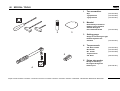
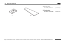
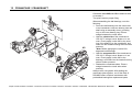
Repair Manual
___
DCS3500
DCS3501
DCS4300
DCS4301
EA3500F
EA3501F
EA4300F
EA4301F
MEA3500L
MEA3500M
MEA4300G
MEA4300L
Caution:
Before doing any maintenance or service work, the combination switch must be engaged in the service position, in
order to prevent unintended starting by the easy start system!
www.dolmar.de
Reparaturanleitung
PS-4600
/ PS-5000
Repair
manual DCS3500
/ DCS3501
/ DCS4300 / DCS4301 / EA3500F / EA3501F / EA4300F / EA4301F / MEA3500L / MEA3500M / MEA4300G / MEA4300L
1
CONTENTS
___
Page
Technical data ........................................................................................................................................................................... 3
Troubleshooting ........................................................................................................................................................................ 4
00
Special tools.......................................................................................................................................................................... 5 - 7
01
Sprocket guard / Chain tensioning system ................................................................................................................................ 8
02
Clutch drum with chain sprocket ............................................................................................................................................... 9
03
Chain brake / Guide bar bolt ............................................................................................................................................ 10 - 11
04
Clutch ................................................................................................................................................................................ 12 - 13
05
Oil pump................................................................................................................................................................................... 14
06
Starter ...................................................................................................................................................................................... 15
07
Ignition system (trouble-shooting) ............................................................................................................................................ 16
07
Ignition system ................................................................................................................................................................. 17 – 18
08
Carburetor ........................................................................................................................................................................ 19 – 20
09
Vibration damper...................................................................................................................................................................... 21
10
Tank ................................................................................................................................................................................. 22 – 23
11
Cylinder / Piston .............................................................................................................................................................. 24 – 26
12
Crankcase / Crankshaft ........................................................................................................................................................... 27
13
Torques ................................................................................................................................................................................... 28
Reparaturanleitung
PS-4600
/ PS-5000
Repair
manual DCS3500
/ DCS3501
/ DCS4300 / DCS4301 / EA3500F / EA3501F / EA4300F / EA4301F / MEA3500L / MEA3500M / MEA4300G / MEA4300L
2
TECHNICAL DATA
___
DCS3500 / DCS3501
1)
2)
Stroke volume
Bore
Stroke
Max. power at speed
Max. torque at speed
Idling speed / max. engine speed with bar and chain
Clutch engagement speed
Sound pressure level at the workplace LpA av per ISO/CD 22868 1)
Sound power level LWA av per ISO/CD 22868 1)
Vibration acceleration ah,w eq per ISO 22867 1)
- Tubular handle
- Rear handle
Carburetor (diaphragm, choke flap carburetor)
Ignition system
Spark plug
Electrode gap
cm3
mm
mm
kW / 1/min
Nm / 1/min
1/min
1/min
dB (A)
dB (A)
or spark plug
Typ
Fuel consumption at max. load per ISO 7293
Specific consumption at max. load per ISO 7293
Fuel tank capacity
Chain oil tank capacity
Mixture ratio (fuel/two-stroke oil)
- when using DOLMAR oil
- when using Aspen Alkalyt (two-stroke fuel)
- when using other oils
Chain brake
Chain speed at max. power
Sprocket pitch
Number of teeth
Chain type
Pitch / gauge
Guide bar, length of a cut
Guide-bar type
Weight (fuel tank empty, without chain, guide bar and accessories)
kg/h
g/kWh
l
l
m/s2
m/s2
Typ
Typ
Typ
mm
m/s
inch
Z
inch
cm
kg
EA3500F / EA3501F
MEA3500M / MEA 3500L
DCS4300 / DCS4301
34.7
38
30.6
1.5 / 9,500
1.9 / 6,500
EA4300F / EA4301F
MEA4300G / MEA4300L
42.4
42
30.6
1.7 / 9,500
2.1 / 6,500
2,800 / 13,500
5,100
100.8
110
4.3
3.6
membrane carburetor
electronic
NGK BPMR 7A
NGK CMR7A-5
0.5
BOSCH WSR 6F,
-CHAMPION RCJ 6Y
0.79
526
0.48
0.28
50 : 1 / 100: 1 (HP-100)
50 : 1 (2%)
50 : 1 (quality grade JASO FC or ISO EGD)
engages manually or in case of kickback
18.1
3/8
6
see the spare-parts list
3/8 / 0.050 (1.3)
30, 35, 40
see the spare-parts list
2)
4.7 / 4.8
4.8 / 4.9 2)
2.0 / 9,500
2.4 / 6,500
2.2 / 9,500
2.6 / 6,500
2,800 / 13,500
5,100
100.8
110
3.6
3.2
membrane carburetor
electronic
NGK BPMR 7A
NGK CMR7A-5
0.5
BOSCH WSR 6F,
-CHAMPION RCJ 6Y
0.96
480
0.48
0.28
50 : 1 / 100: 1 (HP-100)
50 : 1 (2%)
50 : 1 (Qualitätsstufe JASO FC oder ISO EGD)
engages manually or in case of kickback
18.3
.325
7
see the spare-parts list
.325 / 0.050 (1.3)
33, 38, 45
see the spare-parts list
2)
4.7 / 4.8
4.8 / 4.9 2)
Figures derived in equal part from idling, full-load and racing speed.
On models with catalytic converter.
Reparaturanleitung
PS-4600
/ PS-5000
Repair
manual DCS3500
/ DCS3501
/ DCS4300 / DCS4301 / EA3500F / EA3501F / EA4300F / EA4301F / MEA3500L / MEA3500M / MEA4300G / MEA4300L
3
TROUBLESHOOTING
___
Malfunction
System
Observation
Cause
Chain does not run
Chain brake
Engine runs
Chain brake actuated, Chain too tight
Engine does not start
or
Ignition system
Ignition spark
Malfunction in fuel supply system, pressure system,
mechanical malfunction.
only with difficulty
No ignition spark
STOP switch stuck in service position, fault or shortcircuit in the wiring,
plug cap or spark plug defective,
Fuel supply
Fuel tank is filled
gap between ignition module and flywheel uneven or too
wide
Combination switch in Choke position,
carburetor defective, suction head dirty,
fuel line bent, leaky or interrupted.
Inside system
Cylinder base packing ring defective, radial shaft
packings defective,
Outside
cylinder or piston rings defective
Mechanical malfunction
Starter does not engage
Spark plug does not seal.
Multiple systems
Engine speed about
Carburetor too lean
4,500 - 6,000 rpm
Bleed air at cylinder and/or rubber induction piece
Compression
Spring in starter broken, broken parts inside the engine.
Engine speed gets
“stuck”
Fuel line bent, throttle link stuck
Warm engine won’t
start
Carburetor
Fuel tank is filled
Wrong carburetor adjustment
Ignition spark
Flooded from choke use
Piston ring worn (max. thrust play 0.5 mm)
Engine starts, but
Fuel supply
Fuel tank is filled
Wrong idling adjustment, suction head or carburetor dirty,
tank venting defective, fuel line interrupted, cable
defective, Choke flap closed, decompression valve dirty
Several systems
Engine is idling
Air filter dirty, incorrect carburetor setting, muffler
clogged, exhaust channel in cylinder clogged, spark
arrester screen clogged.
No oil on the chain
Oil tank empty
dies immediately
Insufficient power
may be involved
simultaneously
No chain lubrication
Oil tank/pump
Oil guide groove dirty, Oil suction head dirty
Oil pump adjusting screw incorrectly adjusted
Oil pump worm drive gear defective
Reparaturanleitung
PS-4600
/ PS-5000
Repair
manual DCS3500
/ DCS3501
/ DCS4300 / DCS4301 / EA3500F / EA3501F / EA4300F / EA4301F / MEA3500L / MEA3500M / MEA4300G / MEA4300L
4
00 SPECIAL TOOLS
___
1
Torx screwdriver
Grip
T-grip 200 mm
T-grip 100 mm
2
Mandrel
Disassembly mandrel for
tapping out the flywheel
without damage to
the crankshaft thread
1
2
(944.500.860)
(944.500.862)
(944.500.861)
(944.500.880)
3
3
Setting gauge
Gauge for measuring the gap
between flywheel and
armature
(944.500.891)
4
Torque wrench
3/8” Drive socket
Bit 152 mm
Bit 49 mm
Torque wrench
3/8” Drive
5
5
(944.500.864)
(944.500.865)
(944.500.866)
(950.230.000)
Piston stop wedge
Wedge for blocking
the engine through the
exhaust port
(944.602.001)
4
Reparaturanleitung
PS-4600
/ PS-5000
Repair
manual DCS3500
/ DCS3501
/ DCS4300 / DCS4301 / EA3500F / EA3501F / EA4300F / EA4301F / MEA3500L / MEA3500M / MEA4300G / MEA4300L
5
00 SPECIAL TOOLS
___
6
Piston ring tensioner
Piston ring band and
assembly tool for cylinders
7
(944.600.001)
Assembly and disassembly wrench
Wrench for disassembling and
assembling the centrifugal
clutch
(944.500.590)
6
7
8
8
Pressure gauge
Pressure guage for checking
the carburetor fuel valve
(956.004.000)
9
Tachometer
Electronic tachometer for measuring
the engine speed of
2- and 4-stroke engines
(950.233.220)
10 3/8” socket
10
9
Installation/removal of
Spark plug, clutch
(944.500.864)
11 Needle-nose pliers
Various assembly/
Disassembly tasks
(944.603.400)
12 Disassembly hook
Removal/installation
Brake band spring
(950.237.000)
13 Over/underpressure pump
11
12
13
For checking sealing of
radial rings and gaskets
Reparaturanleitung
PS-4600
/ PS-5000
Repair
manual DCS3500
/ DCS3501
/ DCS4300 / DCS4301 / EA3500F / EA3501F / EA4300F / EA4301F / MEA3500L / MEA3500M / MEA4300G / MEA4300L
(957.004.001)
6
00 SPECIAL TOOLS
___
14 Sealing plate
For sealing intake side
(944.603.020)
15 Sealing plate
For sealing exhaust side
14
(944.603.170)
15
Reparaturanleitung
PS-4600
/ PS-5000
Repair
manual DCS3500
/ DCS3501
/ DCS4300 / DCS4301 / EA3500F / EA3501F / EA4300F / EA4301F / MEA3500L / MEA3500M / MEA4300G / MEA4300L
7
01 SPROCKET GUARD / CHAIN TENSIONING SYSTEM
___
1
Remove the sprocket guard, bar, and chain.
CAUTION: Do not work on the chain brake
unless the spring is detensioned!
If necessary, turn adjusting screw 1 clockwise,
until the fastening screw is accessible.
Unscrew the fastening screw and pull the
chain tensioner up and out.
Assembly
Grease spindle and worm gear with multipurpose grease (944.360.000).
Chain tensioner
Carefully take the chain guide cover off the
guide bar bolts.
Unscrew 4 screws, and remove the spike bar
and the cover.
Chain tensioner function
An angled worm drive converts the turns of
the adjustment screw 1 to forward or
backward motion of the tensioning pin.
Reparaturanleitung
PS-4600
/ PS-5000
Repair
manual DCS3500
/ DCS3501
/ DCS4300 / DCS4301 / EA3500F / EA3501F / EA4300F / EA4301F / MEA3500L / MEA3500M / MEA4300G / MEA4300L
8
02 CLUTCH DRUM AND CHAIN SPROCKET
___
Clutch drum with sprocket and needle
bearing
4
Check the chain sprocket 2 for damage and
wear.
Important customer information:
3
Before installing a new saw chain, always
check the condition of the chain sprocket. A
worn chain sprocket will damage a new saw
chain, and must be replaced.
Check the clutch drum needle bearing for
wear and damage.
2
Remove the sprocket guard, bar, and chain.
Check the inside of the clutch drum for
damage and wear.
Remove the circlip 4 with the universal
wrench.
Remove cup washer 3.
Pull the handguard towards the front grip only
as far as necessary so the clutch drum can be
removed.
Assembly the bearing with multi-purpose highperformance grease (944.360.000).
1
Replace the clutch drum if damaged or worn.
Note: Always use a new circlip 4
(927.408.000)!
When assembling the clutch drum, make
sure that the lug of the oil pump drive 1 is
not positioned on the oil pump drive. When
inserting, turn the clutch drum slightly.
Reparaturanleitung
PS-4600
/ PS-5000
Repair
manual DCS3500
/ DCS3501
/ DCS4300 / DCS4301 / EA3500F / EA3501F / EA4300F / EA4301F / MEA3500L / MEA3500M / MEA4300G / MEA4300L
9
03 CHAIN BRAKE / GUIDE BAR BOLT
___
3
1
2
Removing the brake band
Secure the chain saw from slipping (vise).
CAUTION: Wear protective gloves to
prevent cuts!
Using the disassembly hook (Chap. 00, Pos.
12), disengage the brake band spring 3.
Remove the sprocket guard, bar, and chain.
Remove the clutch drum, see Chapter 02.
Push the hand guard forward to engage the
chain brake. This tensions the brake band
spring.
Remove the cover plate, see Chapter 01.
Fold the brake band 1 upward and turn it out
of the disengagement mechanism 2.
Reparaturanleitung
PS-4600
/ PS-5000
Repair
manual DCS3500
/ DCS3501
/ DCS4300 / DCS4301 / EA3500F / EA3501F / EA4300F / EA4301F / MEA3500L / MEA3500M / MEA4300G / MEA4300L
10
03 CHAIN BRAKE / GUIDE BAR BOLT
6
___
7
5
4
Remove the circlip 7.
Replacing the guide bar bolt
Unscrew bolt 4 and pull out the sleeve 5.
Pull the disengagement mechanism up in
parallel with the axes.
Screw two nuts onto the bar bolt and
counterlock them.
Push handguard arm 6 from its position over
the hood towards the muffler.
Pull off the handguard with gentle back-andforth motion.
Unscrew the bar bolt.
Assembly: Apply Loctite 243 (980.009.000) to
the guide bar bolts and turn them all the way
in.
Remove the handguard and
disengagement mechanism
When reassembling always use a new
circlip 7 (927.304.000)!
Assemble the handguard and disengagement
mechanism, brake band and brake band
spring in reverse order.
Reparaturanleitung
PS-4600
/ PS-5000
Repair
manual DCS3500
/ DCS3501
/ DCS4300 / DCS4301 / EA3500F / EA3501F / EA4300F / EA4301F / MEA3500L / MEA3500M / MEA4300G / MEA4300L
11
04 CLUTCH
2
___
1
3
4
Disassembly
CAUTION: To prevent cuts, wear protective
gloves!
Remove the sprocket guard, bar and chain.
Pull the handguard towards the front handle to
release the chain brake if necessary.
Remove the clutch drum, see Chapter 02.
Remove the muffler. To do this, unscrew the 3
screws 1 and remove the upper muffler half 2.
Move piston to bottom dead centre (visible
through the exhaust opening).
Press the piston stop wedge 3 (cap. 00, pos.
5) into the exhaust opening.
5
Insert wrench 4 (Chap. 00, Pos. 7) into the
clutch and use a socket wrench 5 to turn in
the direction of the arrow (left-hand thread) to
loosen and remove the clutch.
Turn the clutch over and remove the disc.
Note: Before the piston stop wedge is
pressed into the exhaust opening, it is
necessary to remove the carbon insert in the
exhaust.
The flyweights can now be pushed off the
guide axially in one direction.
CAUTION: If a catalytic converter is being
used, the muffler will be very hot after
operation!
Reparaturanleitung
PS-4600
/ PS-5000
Repair
manual DCS3500
/ DCS3501
/ DCS4300 / DCS4301 / EA3500F / EA3501F / EA4300F / EA4301F / MEA3500L / MEA3500M / MEA4300G / MEA4300L
12
04 CLUTCH
___
Inserting the flyweights
Installing the clutch
Hook the springs as shown in the illustration.
Press the disc onto the clutch. It must be flat
and be engaged.
Then press the flyweights onto the guide. To
do this, first push on two flyweights half-way,
then put on the third flyweight by setting it on
its edge.
Press the flyweights all the way onto the
guide.
CAUTION: Note the position of the springs.
Do not replace springs individually! If a
spring breaks or is fatigued, all three
springs must be replaced. The springs
must not touch the cover.
Installing the clutch
Install the clutch with the arrow marking point
up.
CAUTION: Before installing the clutch,
disassemble the starter in order to prevent
damage to the starting ratchets
The illustration shows the inside of the clutch.
Reparaturanleitung
PS-4600
/ PS-5000
Repair
manual DCS3500
/ DCS3501
/ DCS4300 / DCS4301 / EA3500F / EA3501F / EA4300F / EA4301F / MEA3500L / MEA3500M / MEA4300G / MEA4300L
13
05 OIL PUMP
___
1
2
4
2
9
1
3
A
4
3
The suction line 4 remains in the crankcase. It
extends into the oil tank. To remove it, carefully
pull on the connection to the oil pump.
General
The oil pump is driven by the clutch drum. Lugs
on the clutch drum transfer the power to the
drive arms of the oil pump drive 1.
The drive worm of the oil pump drive engages
in the teeth of the oil pump 3.
This means that oil is pumped only when the
chain is running.
The oil flow rate can be adjusted with adjusting
screw A:
• Turn right for more oil
• Turn left for less oil
Disassembly
Remove the clutch drum and clutch, see
chapter 04. Remove brake band, see chapter 03.
Turn the oil pump drive 1 counter-clockwise
and pull it off the shaft.
Pull the oil pressure line 2 from the oil pump.
Unsrew 2 screws 4 and remove the oil pump.
Removing the oil pump
Pull the plastic housing off the oil pump by
carefully spreading it apart in the area of the
holes marked 5 in the illustration.
Push the adjusting screw 6 up against the
spring pressure and turn it until the pin 7 goes
into the assembly slit 7. If necessary press the
supply piston 8 in somewhat.
Note: For assembly put the adjusting screw in
stop positions 2 or 3, not in one of the outer
stops.
5
8
Removing the oil tank vent
6
Note: The ventilation valve must be pulled out.
It cannot be knocked into the tank.
7
Reparaturanleitung
PS-4600
/ PS-5000
Repair
manual DCS3500
/ DCS3501
/ DCS4300 / DCS4301 / EA3500F / EA3501F / EA4300F / EA4301F / MEA3500L / MEA3500M / MEA4300G / MEA4300L
14
06 STARTER
___
If the spring pops out, put it back into the plastic
housing as shown in the schematic.
5
6
7
1
8
2
Disassembly
9
Unscrew four screws 1.
4
Remove fan housing 2.
Remove air guide 3 from fan housing.
Detension the return spring.
Injury hazard! Unscrew screw 5 only after
detensioning the return spring!
Unscrew screw 5 and remove actuator 6 and
spring 7.
Pull off the cable drum 8.
Knock the fan housing against a tabletop with
the entire contact surface of the hollow side,
so that the return spring cassette 9 pops out
of the fan housing.
CAUTION! The return spring can jump out
of the plastic cassette! Always wear
protective goggles and gloves!
3
Assembly
Note: If installing a new return spring cassette,
grease it on the spring side.
Carefully insert new return spring cassette 9
and push it in. Lightly grease the surface of the
spring and spring cassette with multipurpose
grease (944.360.000).
Thread in a new starter cable (dia 3.5 mm /
1/8“, length 980 mm / 38.5“) as shown in the
illustration, tie a knot (as shown in the
illustration) in both ends, and tighten both knots.
Put on the cable drum 8 and turn it slightly until
the return spring engages.
Insert spring 7 in actuator 6 and insert together
into the cable drum 8 while turning slightly
counter-clockwise. Insert and tighten screw 5.
Tension the return spring clockwise. Turn the
return spring about 6 turns with the aid of the
cable, which should be pressed into the gap in
the cable drum.
Place the air guide 3 in the fan housing and
make sure the two recesses 4 engage.
Position the fan housing 2 correctly on the saw,
press against it slightly, and pull the starter
handle until the starter catches.
Tighten screws 1.
Reparaturanleitung
PS-4600
/ PS-5000
Repair
manual DCS3500
/ DCS3501
/ DCS4300 / DCS4301 / EA3500F / EA3501F / EA4300F / EA4301F / MEA3500L / MEA3500M / MEA4300G / MEA4300L
15
07 IGNITION SYSTEM (TROUBLE-SHOOTING)
Is the spark plug dry and properly installed?
___
no
yes
Remove spark plug. Is the spark plug damaged? Is it the wrong kind of spark plug?
Is there carbon on the electrodes?
yes
no
Is the spark gap correct? (should be 0.5 mm)
no
Install ignition testing lamp.
Alternatively, insert universal wrench between cylinder and hood. The wrench must
have metallic contact with the cylinder. Caution: Do not insert the wrench into the spark
plug hole or hold with hand.
Using insulated pliers, hold the unscrewed spark plug against the wrench.
Caution: Do not hold the spark plug directly against the hole. Detonation hazard!
Pull the starting cable smartly. Is there an ignition spark?
yes
Is there damage to the insulation of the high-voltage cable or the ignition cable,
or to the wires themselves?
no
Is the gap between the flywheel and the ignition module outside of the 0.25-0.3 mm range?
Is the gap uneven? Has the flywheel worn against the ignition module?
Replace spark plug. Use ONLY a spark plug approved by DOLMAR.
See operating manual! Otherwise the ignition module might be damaged.
Eliminate the causes for carbon deposits on electrodes (bad two-stroke oil, wrong mix,
defective air filter, check carburetor adjustment).
Use DOLMAR high-performance two-stroke oil.
no
yes
Is the spark plug oily or does it have carbon deposits on it?
Dry spark plug cap and fasten firmly to spark plug.
If needed, replace the cap or cap spring.
Adjust spark gap.
yes
Wash spark plug in acetone. Do not sandblast!
If necessary, replace spark plug.
Eliminate cause: wrong carburetor setting, too much oil in fuel,
frequent short operations.
no
Replace spark plug and check ignition module for corrosion, if necessary replace.
Has the defect been remedied?
no
yes
Replace high-voltage cable and/or ignition cable. Has the defect been remedied?
no
yes
Check radial play of drive shaft, and repair if needed.
Replace ignition module if traces of overheating become visible.
Adjust gap between flywheel and ignition module correctly.
no
no
Remove flywheel and check. Is the flywheel damaged?
Is the positioning key damaged?
yes
Replace flywheel or key. Before installation wipe cone seat at drive shaft
and flywheel with acetone or alcohol to remove any grease.
Tighten fastening nut to the correct torque! Has the defect been remedied?
no
Continue with troubleshooting in fuel system (tank, fuel hose, carburetor).
no
no
Replace ignition module. Has the defect been remedied?
Reparaturanleitung
PS-4600
/ PS-5000
Repair
manual DCS3500
/ DCS3501
/ DCS4300 / DCS4301 / EA3500F / EA3501F / EA4300F / EA4301F / MEA3500L / MEA3500M / MEA4300G / MEA4300L
16
07 IGNITION SYSTEM
Removing the flywheel
Remove starter see chap. 06.
Block the piston, see chap. 04.
Loosen the nut in the direction of the arrow
and remove it along with the washer.
___
Screw the disassembly mandrel (chapter 00
pos. 2) onto the threaded end of the shaft.
Do not screw the mandrel all the way down.
Leave about 2 mm between the mandrel and
the flywheel.
Hold the machine in one hand or place on a
soft surface, and knock the flywheel loose with
a tap on the mandrel.
CAUTION: The cone of the crankshaft must
always be degreased before assembly.
Reparaturanleitung
PS-4600
/ PS-5000
Repair
manual DCS3500
/ DCS3501
/ DCS4300 / DCS4301 / EA3500F / EA3501F / EA4300F / EA4301F / MEA3500L / MEA3500M / MEA4300G / MEA4300L
17
07 IGNITION SYSTEM
___
13
1
12
2
15
14
16
3
11
10
9
4
5
6
7
8
Removing the ignition armature
Remove cover and air filter.
Unsrew screws 2 and 12.
Pull fuel lines 6 from the primer.
Push detent 7 on the primer 8 slightly and pull
out the primer.
Disengage short-circuit wire 10 from the
rocker 11 and pull the rocker up and out.
Unscrew screws 5 and 9.
Unscrew screw 4.
Pull off spark-plug cap 3 and unscrew spark
plug.
Push the spark-plug cap wire grommet out
towards the spark.plug hole.
The cover 1 can now be taken up and off.
Pull short-circuit wire 15.
Installing the ignition armature
Unscrew 2 screws on ignition armature 14.
Note: The high-voltage cable is moulded onto
the ignition system and cannot be replaced
separately.
Remove ignition armature and wire.
Insert the armature and turn the screws in
almost all the way.
Insert the setting gauge 16 (Kapitel 00 Pos. 3)
between the ignition armature and the
fylwheel.
Position the flywheel so that the magnet is
against the armature (gap 0.25 – 0.3 mm).
Press the armature against the gauge towards
the flywheel and tighten the armature screws.
Then check the gap again to make sure it is
correct.
Attach the short-circuit wire 15 and press the
rubber grommet into the carburetor base.
Reparaturanleitung
PS-4600
/ PS-5000
Repair
manual DCS3500
/ DCS3501
/ DCS4300 / DCS4301 / EA3500F / EA3501F / EA4300F / EA4301F / MEA3500L / MEA3500M / MEA4300G / MEA4300L
18
08 CARBURETOR
___
2
1
5
9
3
6
4
Note: If replacing the foam 10 in the
carburetor base, make sure the position is
correct. The opening should be towards the
suction channel, as shown in the illustration.
8
7
10
4
Removing the intake manifold and
carburetor
CAUTION: Completely empty the fuel tank
before disassembling the carburetor!
Remove cover and air filter.
Move combination switch to safety position.
Unscrew 4 screws 1.
Remove intake manifold 2.
Pull fuel lines and pulse line 3 from the
carburetor.
CAUTION: There is fuel in the line. Catch
escaping fuel with a cloth.
Disengage throttle link 4.
Note: When reassembling, engage the
linkage in the marked hole (arrow).
Removing the carburetor bottom
Remove throttle linkage 4.
Remove cover (see chapter 07).
Pull short.circuit wire 5 from the ignition
armature.
Unscrew screw 6 and remove along with the
contact spring 7.
Unscrew screw 8.
Detach pulse line 9.
The carburetor base can now be removed
along with the combination switch.
Note: When assembling, make sure that the
short-circuit switch is pulled through the
rubber grommet as far towards the carburetor
as possible, in order to prevent the wire from
touching the cylinder.
Note: Do not twist the fuel line during
assembly.
Reparaturanleitung
PS-4600
/ PS-5000
Repair
manual DCS3500
/ DCS3501
/ DCS4300 / DCS4301 / EA3500F / EA3501F / EA4300F / EA4301F / MEA3500L / MEA3500M / MEA4300G / MEA4300L
19
08 CARBURETOR
___
General check
• Screen 7 for contamination
• Pulse hole for contamination
Basic Setting (without Limiter Caps)
L= 1 1/2
H= 3
Check control parts
NOTE: Adjust the carburetor only
using a tachometer.
Pressure test
Connect the pressure gauge (chapter
00 item 8 oder 13) to the carburetor
fuel connection 1.
Set up a pressure of max. 0.5 bar.
If the pressure falls, check the
following parts:
• Correct assembly of Control assy
(Control lever, Inlet needle, Lever
spring, lever axle)
• Check seat of inlet needle for
dirt/foreign parts, clean if necessary
• Replace control assy
• Replace gasket 6 and diaphragm 5
of the pump side
(control lever/inlet needle):
Check the tip of the inlet needle for wear.
Check control lever for correct installation, see
illustration to the left.
If the control lever is too low:
• Lack of fuel
• Poor acceleration
• No maximum power
If the control lever is too high:
• Carburetor flooding
• Starting problems
• Poor idling
• Poor transition
Control lever
Check the pump diaphragm:
• If pump diaphragm is dented, torn, or creased,
• If valve flaps are bent,
replace the diaphragm and gasket
Check control diaphragm:
• If control diaphragm is bent or torn, or there
is obvious wear at the button 8.
• If it does not return to its original position
when pulled out of it,
Control lever
Control lever
Control lever
Correctly
installed
Too high
Too low
replace the diaphragm and gasket.
Reparaturanleitung
PS-4600
/ PS-5000
Repair
manual DCS3500
/ DCS3501
/ DCS4300 / DCS4301 / EA3500F / EA3501F / EA4300F / EA4301F / MEA3500L / MEA3500M / MEA4300G / MEA4300L
20
09 VIBRATION DAMPER
___
Disassembly
Springs 1 and 2
Remove the sprocket guard and chain brake
cover, see chap. 01.
Loosen screws with Torx screwdriver (chap.
00 pos. 1) and remove.cushion spring.
Spring 3
Remove starter housing (see chap. 06) and
hood (see chap. 07).
3
Loosen and remove screws with Torx
screwdriver (chap. 00 pos. 1).
4
Pull out cushion spring.
Spring 4
Remove the side brace cover.
2
1
Loosen and remove screw with Torx
screwdriver (chap. 00 pos. 1)
Remove cushion spring. Remove spring
retainer.
Note: During assembly, insert spring retainer
between the cushion spring and the cylinder.
Reparaturanleitung
PS-4600
/ PS-5000
Repair
manual DCS3500
/ DCS3501
/ DCS4300 / DCS4301 / EA3500F / EA3501F / EA4300F / EA4301F / MEA3500L / MEA3500M / MEA4300G / MEA4300L
21
10 TANK
___
The throttle lever has a slot 2 at the hinge.
In assembly, first place the throttle lever
spring 3 on the throttle lever, then push the
lever onto the hinge iwth the slot. The throttle
lever must be turned by 180° to do this.
1
The throttle lever block 4 can easily be
pushed through the diagonals on the seat.
The spring is engaged in the throttle lever as
shown below.
3
Grip mechanism
Unscrew screw 1 and pull off the top grip half
near the screw seat.
2
Note: When removing the throttle the following
must be done:
• Remove intake manifold and carburetor
• Remove hood and carburetor base
4
See chapters 07 and 08.
Reparaturanleitung
PS-4600
/ PS-5000
Repair
manual DCS3500
/ DCS3501
/ DCS4300 / DCS4301 / EA3500F / EA3501F / EA4300F / EA4301F / MEA3500L / MEA3500M / MEA4300G / MEA4300L
22
10 TANK
___
Removal
Pressure test
Vacuum testing ventilation valve 6
To remove the tank, first remove the hood (see
chap. 07), the starter housing (see chap. 06)
and the vibration damper.
Attach the over/underpressure pump (chap. 00
pos. 13) to one of the two fuel lines 5 . Seal off
the second line.
Set up a pressure of max. 0.3 bar.
If the pressure drops off, check the following:
• Air valve
• Bothe fuel lines
• Fuel nipple
• Tank cap seal
• Check tank for holes
Note: Detergent can be used to localise leaks.
Attach the over/underpressure pump as
described.
Close off the installation opening of the air valve
with your thumb (dampen it slightly).
Set up a negative pressure of max 0.5 bar.
This negative pressure must not change as long
as the opening is sealed. When you take your
thumb off the air valve, the negative pressure
must quickly return to normal.
Before separating the engine unit and the tank,
the lateral fastening screws on the front grip will
have to be unscrewed.
5
8
Parts
To remove the suction head 7 pull it through the
tank opening with a hooked wire.
Note: Do not use pliers,as this may damage the
line. Do not pull on the suction head or fuel line,
as this can pull off the fuel nipple inside the
tank.
Fuel lines 5 can be pulled off the fuel nipple.
Fuel line length:
Return
L = 118 mm (dia. 2.5/5.5)
Supply
L = 93 mm (dia 5.5 / 3)
Carefully lever out fuel nipple 8 with a sharp
flat-bladed screwdriver.
Note: Do not lever against the line connections,
as this can break them off.
Lever off ventilation valve 6 with a small
screwdriver.
6
7
Reparaturanleitung
PS-4600
/ PS-5000
Repair
manual DCS3500
/ DCS3501
/ DCS4300 / DCS4301 / EA3500F / EA3501F / EA4300F / EA4301F / MEA3500L / MEA3500M / MEA4300G / MEA4300L
23
11 CYLINDER / PISTON
1
2
3
___
Vacuum testing
If correct carburetor setting is not possible, it will
be necessary to test the sealing of the engine.
Remove hood (see chap. 07).
Remove carburetor (see chap. 08).
To seal off the exhaust side, insert the sealing
lip 1 (chap. 00 pos. 15) between the muffler and
the cylinder. First remove the muffler and
unscrew the fastening bolt from the cylinder.
To seal off the intake side, install the sealing
plate 2 (chap. 00 pos. 14) in the place of the
carburetor.
Connect the over/underpressure pump to the
connection on the sealing plate 3.
Seal off the pulse line and bring the cylinder to
top dead center.
Set up a pressure of max. 0.3 bar.
If the pressure rises within 20 seconds, the
following conditions may exist:
• Radial ring leaking
• Cylinder base gasket leaking
• Crankcase gasket leaking
• Crack in crankcase
• Crack in cylinder
• Spark plug leaking
• Rubber intake on cylinder leaking
• Defective pulse line
Note: Detergent can be used to localise leaks.
Reparaturanleitung
PS-4600
/ PS-5000
Repair
manual DCS3500
/ DCS3501
/ DCS4300 / DCS4301 / EA3500F / EA3501F / EA4300F / EA4301F / MEA3500L / MEA3500M / MEA4300G / MEA4300L
24
11 CYLINDER / PISTON
1
2
___
Note: If there is a leak into the oil tank, it will
not be possible to fully identify the leak. If
pressure remains steady in the crankcase
after shutting off the oil line hole, for example
with a rubber stopper (see chap. 05), it is an
indication that there is a defect in the
crankcase gasket to the oil tank.
Always perform sealing tests with
underpressure!
If a leak is diagnosed, it can be found
using overpressure and detergent or
similar liquid.
3
Reparaturanleitung
PS-4600
/ PS-5000
Repair
manual DCS3500
/ DCS3501
/ DCS4300 / DCS4301 / EA3500F / EA3501F / EA4300F / EA4301F / MEA3500L / MEA3500M / MEA4300G / MEA4300L
25
11 CYLINDER / PISTON
___
7
6
8
4
5
Removing the cylinder and piston
Disconnect the intake and exhaust sides.
Unscrew the spark plug.
Remove the ignition armature.
Disassemble the vibration damper between
the cylinder and front grip.
Unscrew 4 screws 4 and pull the cylinder up
and off.
Note: After pulling off the cylinder 6, support
the piston with the assembly tool (chap. 00
pos. 6).
Remove spring ring 5 with needle-nose pliers.
Assembling the cylinder and piston
Use a new gasket!
Note: The protuberance on the gasket must
point towards the induction side.
Before assembly, lightly oil the cylinder race
and piston!
Push assembly tool 7 under the piston.
Turn the opening on the piston ring towards the
piston ring lock.
Use the piston ring tensioner 8 to press the
piston ring together.
Push the cylinder onto the piston. Let the piston
ring tensioner slide down with it.
Remove the assembly tool and piston ring
tensioner and press the cylinder all the way
down.
Hand-tighten the screws 4 lightly crosswise,
and then tighten to the correct torque, again
crosswise.
Reparaturanleitung
PS-4600
/ PS-5000
Repair
manual DCS3500
/ DCS3501
/ DCS4300 / DCS4301 / EA3500F / EA3501F / EA4300F / EA4301F / MEA3500L / MEA3500M / MEA4300G / MEA4300L
26
12 CRANKCASE / CRANKSHAFT
___
Crankcase sides MS and CS are attached with
six screws 1.
Two pins 2 ensure proper fitting.
When assembling the ball bearings, note the
following:
•
Press one ball bearing onto the clutch side
of the crankshaft. Press the bearing onto the
shaft using an assembly sleeve, pressing
only on the inner bearing ring. Place a
wedge between the crank webs.
•
Heat the clutch side of the crankcase to
150-160° C using a hot-air blower or in an
oven. Evenly apply Loctite 620 to the outer
ring of the bearing (on the crankshaft), and
insert into the heated housing without further
pressure.
Note: Before applying the Loctite 620,
degrease both bearings.
•
Heat the magneto side of the crankcase to
150-160° C using a hot-air blower or in an
oven. Evenly apply Loctite 620 to the
bearings, and insert into the heated housing
without further pressure.
•
Reattach the crankcase sides. Place a
wedge between the crank webs when
pressing.
MS
2
3
KS
4
5
1
Always use a new gasket. After bolting the
crankcase sides together, cut off the flash 3.
DOLMAR offers complete crankcases with
preinstalled bearings as replacement parts.
Reparaturanleitung
PS-4600
/ PS-5000
Repair
manual DCS3500
/ DCS3501
/ DCS4300 / DCS4301 / EA3500F / EA3501F / EA4300F / EA4301F / MEA3500L / MEA3500M / MEA4300G / MEA4300L
27
13 TORQUES
Fastener
Crankcase sides
Cylinder on crankcase
Carburetor bottom on crankcase
Muffler on cylinder
Front shell to muffler
Front shell to cylinder
Carburetor / intake manifold in carburetor flange
Intake manifold on carburetor bottom
Intake manifold to hood
Oil pump to crankcase
Oil pump cover to crankcase
Clutch to crankshaft
Transmission cover chain tensioner to
crankcase
Mounting bolt in bar flange
Mounting bolt in bar flange
Sprocket guard mounting
Chain brake cover
Ignition mounting in crankcase
Flywheel nut fastening
Starter housing to crankcase
Hood
Handguard bearing to magneto side
Grip/rear handle to tank
Front handle on tank, side
Front handle on tank, bottom
Front handle side cover on tank
Damping spring fastening on cylinder
Damping spring / tank, mag. side rear
Damping spring / tank, cyl. side front
Damping spring cylinder / handle side cover
Damping spring / crankcase, mag. side
Damping spring / crankcase, cyl. side
Damping spring / crankcase, cyl. side
Spark plug
Pawls to magnet wheel
Mounting bolt TLC
___
Part No.
908.405.205
908.405.205
908.005.165
908.005.165
908.005.165
908.305.405
908.004.405
913.455.164
913.455.164
908.005.165
908.005.165
---
Size
M 5 x 20 Torx
M 5 x 20 Torx with lock teeth
M 5 x 16 Torx
M 5 x 16 Torx
M 5 x 16 Torx
M 5 x 20 x 40 Torx
M 4 x 40 Torx
5,5 x 16 Torx
5,5 x 16 Torx
M 5 x 16 Torx
M 5 x 16 Torx
M 12 x 1 L with assembly wrench for centrifugal clutch
Qty.
6x
4x
2x
2x
2x
1x
2x
1x
1x
1x
1x
1x
Torque
10 +/-1
12 +/-1
5 +/-0,5
8 +/-1
8 +/-1
8 +/-1
3 +/-1
3 +/-1
5 +/-1
5 +/-1
5 +/-1
35 +/-2,5
915.135.100
195.232.010
195.232.020
923.208.004
908.105.126
908.805.205
920.308.024
908.005.165
908.005.165
908.005.165
913.455.164
913.455.164
913.455.164
913.455.164
908.005.165
913.455.164
913.455.164
913.455.164
908.005.165
908.005.165
908.005.165
965.603.021
170.166.041
195.232.040
BZ 3,5 x 9,5
M 8 SK 6 / M8
M 8 SK 6 / M8 x 1
M 8, SW 13, 6KT-nut with flange
M 5 x 12 Torx
M 5 x 20 Torx
M 8 x 1 / SW 13
M 5 x 16 Torx
M 5 x 16 Torx
M 5 x 16 Torx
5,5 x 16 Torx
5,5 x 16 Torx
5,5 x 16 Torx
5,5 x 16 Torx
M 5 x 16 Torx
5,5 x 16 Torx
5,5 x 16 Torx
5,5 x 16 Torx
M 5 x 16 Torx
M 5 x 16 Torx
M 5 x 16 Torx
M 14 x 1,25 / SW 19
---
1x
2x
1x
2x
2x
2x
1x
4x
3x
1x
1x
2x
2x
2x
1x
1x
1x
1x
1x
2x
2x
1x
2x
1x
1,5 +/-0,2
15 +/-1
15 +/-1
1 +/-0,5
5 +/-0,5
5 +/-0,5
25 +/-1
5 +/-0,5
5 +/-0,5
5 +/-0,5
3 +/-1
5 +/-1
5 +/-1
3 +/-1
5 +/-0,5
5 +/-1
5 +/-0,5
5 +/-0,5
5 +/-0,5
5 +/-0,5
5 +/-0,5
15 +/-5
8 +/-1
10 +/-1
Reparaturanleitung
PS-4600
/ PS-5000
Repair
manual DCS3500
/ DCS3501
/ DCS4300 / DCS4301 / EA3500F / EA3501F / EA4300F / EA4301F / MEA3500L / MEA3500M / MEA4300G / MEA4300L
28
NOTES
Reparaturanleitung
PS-4600
/ PS-5000
Repair
manual DCS3500
/ DCS3501
/ DCS4300 / DCS4301 / EA3500F / EA3501F / EA4300F / EA4301F / MEA3500L / MEA3500M / MEA4300G / MEA4300L
___
29
NOTES
Reparaturanleitung
PS-4600
/ PS-5000
Repair
manual DCS3500
/ DCS3501
/ DCS4300 / DCS4301 / EA3500F / EA3501F / EA4300F / EA4301F / MEA3500L / MEA3500M / MEA4300G / MEA4300L
___
30
NOTES
Reparaturanleitung
PS-4600
/ PS-5000
Repair
manual DCS3500
/ DCS3501
/ DCS4300 / DCS4301 / EA3500F / EA3501F / EA4300F / EA4301F / MEA3500L / MEA3500M / MEA4300G / MEA4300L
___
31
___
Reparaturanleitung
PS-4600
/ PS-5000
Repair
manual DCS3500
DCS3501
/ DCS4300
/ DCS4301
/ EA3500F
/ EA3501F / EA4300F / EA4301F / MEA3500L / MEA3500M / MEA4300G / MEA4300L
Makita
Werkzeug
GmbH
• /Postfach
70 04
20 • D-22004
Hamburg
• Germany
620
Form: 995 728 62032