1
Chapter 8
Switching
Introduction ................................................................................................... 8-5
Switch Ports ................................................................................................... 8-6
Enabling and Disabling Switch Ports ........................................................ 8-6
Autonegotiation of Port Speed and Duplex Mode .................................... 8-7
Port Trunking .......................................................................................... 8-8
Link Aggregation Control Protocol (LACP) ............................................... 8-9
Packet Storm Protection ........................................................................ 8-10
Port Mirroring ....................................................................................... 8-11
Port Security .......................................................................................... 8-11
Virtual Local Area Networks (VLANs) ............................................................ 8-12
Dynamic VLAN Assignment ................................................................... 8-13
802.1x Guest VLAN ............................................................................... 8-14
VLAN Tagging ....................................................................................... 8-15
VLAN Membership of Untagged Packets ............................................... 8-18
Creating VLANs ..................................................................................... 8-19
Summary of VLAN Tagging Rules ........................................................... 8-21
VLAN Interaction with Trunk Groups ...................................................... 8-21
Static and Dynamic VLANs ..................................................................... 8-21
Protected VLANs ................................................................................... 8-22
Private VLANs ........................................................................................ 8-22
VLAN Relaying ............................................................................................. 8-25
Configuring VLAN Relaying ................................................................... 8-26
The Layer 2 Switching Process ...................................................................... 8-27
The Ingress Rules ................................................................................... 8-28
The Learning Process ............................................................................. 8-28
The Forwarding Process ......................................................................... 8-29
Quality of Service .................................................................................. 8-30
The Egress Rules .................................................................................... 8-31
Layer 2 Filtering ........................................................................................... 8-31
Spanning Tree Protocol (STP) ........................................................................ 8-32
Electing a Root Bridge and Designated Bridge ....................................... 8-33
Spanning Tree Modes ............................................................................ 8-33
Rapid Mode Spanning Tree Types ........................................................... 8-34
Spanning Tree and Rapid Spanning Tree Port States ............................... 8-34
Multiple Spanning Trees and STP Interaction with VLANs ....................... 8-35
Overlapping VLANs belonging to Multiple Spanning Tree Instances ........ 8-36
Configuring STP .................................................................................... 8-36
Multiple Spanning Tree Protocol (MSTP) ....................................................... 8-41
Multiple Spanning Tree Regions ............................................................. 8-41
Bridge Protocol Data Units (BPDUs) ........................................................ 8-42
Compatibility with Previous Spanning Tree Protocols .............................. 8-44
8-2
Rapier Switch Software Reference
Configuring MSTP ................................................................................. 8-45
Common and Internal Spanning Tree (CIST) ........................................... 8-51
The Relationship between Spanning Trees and Trunks ............................ 8-55
Hardware Packet Filters ................................................................................ 8-55
Classifier-Based Packet Filters ................................................................. 8-55
Layer 3 Filter Matches ............................................................................ 8-57
Access Control Lists (ACLs) .................................................................... 8-58
Triggers ........................................................................................................ 8-59
Configuration Examples ............................................................................... 8-60
Example Using One Switch to Extend a Local LAN ................................. 8-60
Example of a meshed network without VLANs ...................................... 8-61
VLAN example using untagged ports ..................................................... 8-62
VLAN Example with Tagged Ports .......................................................... 8-63
Example of Meshed Network with VLAN Tagged Ports ........................... 8-65
Command Reference ................................................................................... 8-69
activate mstp migrationcheck port ......................................................... 8-69
activate switch port ............................................................................... 8-70
add lacp port ......................................................................................... 8-71
add mstp msti vlan ................................................................................ 8-73
add stp vlan .......................................................................................... 8-74
add switch filter .................................................................................... 8-75
add switch hwfilter classifier .................................................................. 8-77
add switch l3filter entry ......................................................................... 8-80
add switch l3filter match ....................................................................... 8-83
add switch trunk ................................................................................... 8-86
add vlan bridge ..................................................................................... 8-87
add vlan port ......................................................................................... 8-88
add vlanrelay ......................................................................................... 8-90
create mstp msti .................................................................................... 8-91
create stp .............................................................................................. 8-93
create switch trunk ................................................................................ 8-94
create vlan ............................................................................................ 8-95
create vlanrelay ..................................................................................... 8-96
delete lacp port ..................................................................................... 8-97
delete mstp msti vlan ............................................................................ 8-98
delete stp vlan ....................................................................................... 8-99
delete switch filter ............................................................................... 8-100
delete switch hwfilter classifier ............................................................ 8-100
delete switch l3filter ............................................................................ 8-101
delete switch l3filter entry ................................................................... 8-101
delete switch trunk .............................................................................. 8-102
delete vlan bridge ................................................................................ 8-102
delete vlan port ................................................................................... 8-103
delete vlanrelay ................................................................................... 8-104
destroy mstp msti ................................................................................ 8-105
destroy stp .......................................................................................... 8-105
destroy switch trunk ............................................................................ 8-106
destroy vlan ......................................................................................... 8-107
destroy vlanrelay ................................................................................. 8-107
disable lacp ......................................................................................... 8-108
disable lacp debug .............................................................................. 8-108
disable mstp ........................................................................................ 8-109
disable mstp cist port .......................................................................... 8-109
disable mstp debug ............................................................................. 8-110
disable mstp msti port ......................................................................... 8-111
disable stp ........................................................................................... 8-112
disable stp debug ................................................................................ 8-113
disable stp port ................................................................................... 8-115
disable switch ageingtimer .................................................................. 8-116
Software Release 2.7.3
C613-03098-00 REV A
Switching
8-3
disable switch debug ........................................................................... 8-116
disable switch hwfilter ......................................................................... 8-117
disable switch l3filter ........................................................................... 8-117
disable switch learning ........................................................................ 8-118
disable switch mirror ........................................................................... 8-118
disable switch port .............................................................................. 8-119
disable vlan debug .............................................................................. 8-120
disable vlanrelay .................................................................................. 8-120
disable vlanrelay debug ....................................................................... 8-121
enable lacp .......................................................................................... 8-121
enable lacp debug ............................................................................... 8-122
enable mstp ........................................................................................ 8-122
enable mstp cist port ........................................................................... 8-123
enable mstp debug ............................................................................. 8-124
enable mstp msti port ......................................................................... 8-126
enable stp ........................................................................................... 8-127
enable stp debug ................................................................................ 8-128
enable stp port .................................................................................... 8-130
enable switch ageingtimer ................................................................... 8-131
enable switch bist ................................................................................ 8-132
enable switch debug ........................................................................... 8-135
enable switch hwfilter ......................................................................... 8-136
enable switch l3filter ........................................................................... 8-136
enable switch learning ........................................................................ 8-137
enable switch mirror ............................................................................ 8-137
enable switch port ............................................................................... 8-138
enable vlan debug ............................................................................... 8-139
enable vlanrelay .................................................................................. 8-140
enable vlanrelay debug ........................................................................ 8-141
purge lacp ........................................................................................... 8-141
purge mstp ......................................................................................... 8-142
purge stp ............................................................................................ 8-142
reset lacp port counter ........................................................................ 8-143
reset mstp counter port ....................................................................... 8-143
reset stp .............................................................................................. 8-144
reset switch ......................................................................................... 8-144
reset switch port ................................................................................. 8-145
set lacp port ........................................................................................ 8-146
set lacp priority .................................................................................... 8-147
set mstp .............................................................................................. 8-148
set mstp cist ........................................................................................ 8-151
set mstp cist port ................................................................................. 8-152
set mstp msti ....................................................................................... 8-154
set mstp msti port ............................................................................... 8-155
set stp ................................................................................................. 8-158
set stp port .......................................................................................... 8-161
set switch ageingtimer ........................................................................ 8-164
set switch hwfilter classifier ................................................................. 8-165
set switch l3ageingtimer ...................................................................... 8-167
set switch l3filter entry ........................................................................ 8-168
set switch l3filter match ...................................................................... 8-171
set switch mirror ................................................................................. 8-173
set switch port .................................................................................... 8-174
set switch qos ..................................................................................... 8-179
set switch trunk ................................................................................... 8-180
set vlan port ........................................................................................ 8-181
show lacp ............................................................................................ 8-182
show lacp port .................................................................................... 8-183
show lacp port counter ....................................................................... 8-185
Software Release 2.7.3
C613-03098-00 REV A
8-4
Rapier Switch Software Reference
show lacp trunk .................................................................................. 8-186
show mstp .......................................................................................... 8-187
show mstp cist .................................................................................... 8-189
show mstp cist port ............................................................................. 8-191
show mstp counter port ...................................................................... 8-194
show mstp debug ............................................................................... 8-195
show mstp msti ................................................................................... 8-196
show mstp msti port ........................................................................... 8-198
show stp ............................................................................................. 8-200
show stp counter ................................................................................ 8-203
show stp debug .................................................................................. 8-205
show stp port ...................................................................................... 8-206
show switch ........................................................................................ 8-209
show switch counter ........................................................................... 8-211
show switch debug ............................................................................. 8-213
show switch fdb .................................................................................. 8-214
show switch filter ................................................................................ 8-216
show switch hwfilter ........................................................................... 8-218
show switch l3filter ............................................................................. 8-220
show switch port ................................................................................. 8-222
show switch port counter .................................................................... 8-226
show switch port intrusion .................................................................. 8-229
show switch qos .................................................................................. 8-230
show switch trunk ............................................................................... 8-231
show vlan ............................................................................................ 8-232
show vlan debug ................................................................................. 8-234
show vlanrelay .................................................................................... 8-235
Software Release 2.7.3
C613-03098-00 REV A
Switching
8-5
Introduction
This chapter gives an overview of Layer 1 (the physical layer), 2 (the data link
layer), and 3 (the network layer) switching, and describes the support for
switching and how to configure and operate the switching functions.
The switch, also referred to as a MAC (media access control) bridge, a data link
relay, or a Layer 2 switch, can connect multiple Local Area Network (LAN)
segments together to form an extended LAN. Stations connected to different
LANs can be configured to communicate with one another as if they were on
the same LAN. It can also divide one physical LAN into multiple Virtual LANs
(VLANs). Stations connected to each other on the same extended LAN can be
grouped in separate VLANs, so that a station in one VLAN can communicate
directly with other stations in the same VLAN, but must go through higher
layer routing protocols to communicate with stations in other VLANs.
The switch operates at the data link layer, transparent to higher layer protocols,
transferring frames between the data link layers of the networks to which it is
attached. A bridge accesses each physical link according to the rules for that
particular network. Access may not always be instant, so a bridge must be
capable of storing and forwarding frames. Since the switch can store and
forward frames, it can examine and discard or admit frames according to their
VLAN tag fields. The switch can also examine the address fields of the frames
and forward the frames based on knowledge of which network contains the
station with an address matching the frame’s destination address. In this way,
the switch can act as an intelligent filtering device, redirecting or blocking the
movement of frames between networks.
Because the switch may receive frames faster than it can forward them, the
switch has Quality of Service (QoS) queues in which frames await transmission
according to their priority.
The switch can be used to:
■
Increase the physical extent and/or the maximum number of stations on a
LAN.
LANs are limited in their physical extent by the signal distortion and
propagation delay characteristics of the media. The switch overcomes this
limitation by receiving a frame on one LAN and then retransmitting the
frame on another LAN, using the normal access methods for each LAN. The
physical characteristics of the LAN media also place a practical limit on the
number of stations that can be connected to a single LAN segment. The
switch overcomes this limitation by joining LAN segments together to form
an extended LAN capable of supporting more stations than either of the
individual LANs.
■
Connect LANs that have a common data link layer protocol but different
physical media, for example, Ethernet 10BASET, 100BASET, and 10BASEF.
■
Increase the availability of LANs by allowing multiple redundant paths to
be physically configured, and selected dynamically, using the Spanning
Tree algorithm.
■
Reduce the load on a LAN or increase the effective bandwidth of a LAN,
by filtering traffic.
■
Prioritise the transmission of data with high Quality of Service
requirements.
By using Virtual LANs (VLANs), a single physical LAN can be separated into
multiple Virtual LANs. VLANs can be used to:
Software Release 2.7.3
C613-03098-00 REV A
8-6
Rapier Switch Software Reference
■
Further improve LAN performance, as broadcast traffic is limited to LAN
segments serving members of the VLAN to which the sender belongs.
■
Provide security, as frames are forwarded to those stations belonging to the
sender’s VLAN, and not to stations in other VLANs on the same physical
LAN.
■
Reduce the cost of moving or adding stations to function or security based
LANs, as this generally requires only a change in the VLAN configuration.
Switch Ports
The term port is used frequently in switch terminology. Each port in a switch is
associated with one of the physical interfaces on the switch. Each port is
uniquely identified by a port number. The switch supports a number of
features at the physical level that allows it to be connected in a variety of
physical networks. This physical layer (Layer 1) versatility includes:
■
Enabling and disabling Ethernet ports.
■
Autonegotiation of port speed and duplex mode for all 10/100 Ethernet
ports and copper gigabit ports.
■
Manual setting of port speed and duplex mode for all 10/100 Ethernet
ports and copper gigabit ports.
■
Port trunking.
■
Packet storm protection.
■
Port mirroring.
■
Support for SNMP management.
■
Link triggers for fibre ports.
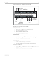
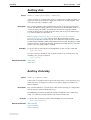
Enabling and Disabling Switch Ports
A switch port that is enabled is available for packet reception and transmission.
Its administrative status in the Interfaces MIB is UP. Conversely, a port that is
disabled is not available for packet reception and transmission. It does not send
or receive frames and its administrative status in the Interfaces MIB is DOWN.
Every port on the switch is enabled by default. A switch port that has been
disabled by the Port Security feature cannot be enabled using the enable
switch port command on page 8-138.
To enable or disable a switch port, use the commands:
enable switch port={port-list|all}
disable switch port={port-list|all}
Resetting ports at the hardware level discards all frames queued for reception
or transmission on the port, and restarts autonegotiation of port speed and
duplex mode. Ports are reset using the command:
reset switch port={port-list|all} [counter]
To display information about switch ports, use the command:
show switch port[={port-list|all}]
Software Release 2.7.3
C613-03098-00 REV A
Switching
8-7
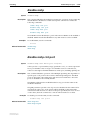
Autonegotiation of Port Speed and Duplex
Mode
Each of the switch ports can operate at either 10 Mbps or 100 Mbps, in either
full duplex or half duplex mode. In full duplex mode, a port transmits and
receives data simultaneously. In half duplex mode, the port either transmits or
receives, but not at the same time. This versatility makes it possible to connect
devices with different speeds and duplex modes to different ports on the
switch. This versatility also requires that each port on the switch know which
speed and mode to use.
Autonegotiation allows the ports to adjust their speed and duplex mode to
accommodate devices connected to them. Each switch port can be either
configured with a fixed speed and duplex mode, or configured to
autonegotiate speed and duplex mode with a device connected to it to
determine a speed and mode that allows successful transmission. An
autonegotiating port adopts the speed and duplex mode required by devices
connected to it. If another autonegotiating device is connected to the switch,
they negotiate the highest possible common speed and duplex mode. Setting
the port to a fixed speed and duplex mode allows it to support equipment that
cannot autonegotiate.
If you override a port’s autonegotiation on Rapier i Series switches by setting
it to a fixed speed/duplex setting, automatic MDI/MDI-X detection is also
overridden. The port defaults to MDI-X.
It is also possible to require a port to operate at a single speed without
disabling autonegotiation by allowing the port to autonegotiate but constrain
the speed/duplex options to the desired combination. For example, if one end
of a link is set to auto and the other to 100mfull, then the auto end selects
100mhalf operation because without the other end autonegotiating, the auto
end has no way of knowing that the fixed end is full duplex capable. If a
particular speed is required, it is better to fix the speed/duplex combination
using one of the autonegotiating speed values. Therefore, using 100mfauto at
one end of a link allows the auto end to autonegotiate 100mfull.
Switch ports autonegotiate by default when they are connected to a new
device. To change this setting, use the command:
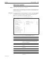
set switch port={port-list|all} speed={autonegotiate|10mhalf|
10mfull|10mhauto|10mfauto|100mhalf|100mfull|100mhauto|
100mfauto|1000mhalf|1000mfull|1000mhauto|1000mfauto}
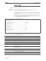
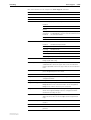
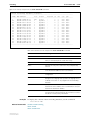
Settings available on different models are shown in Table 8-1 on page 8-8.
Autonegotiation can also be activated at any time after this, on any port that is
set to autonegotiate by using the command:
activate switch port={port-list|all} autonegotiate
The show switch port command displays the port speed and duplex mode
settings.
Software Release 2.7.3
C613-03098-00 REV A
8-8
Rapier Switch Software Reference
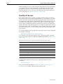
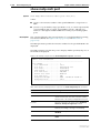
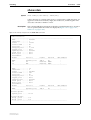
Table 8-1: Port speed and duplex settings for switch ports
Speed
Rapier 24i
Rapier 48i Rapier 24i
Rapier 24i Rapier 16f Rapier 48i
Rapier 48i Rapier G6x Rapier G6x
AT-A40
Rapier 24i
Rapier 16f Rapier G6x AT-A35
AT-A41
AT-A42
AT-A39
Rapier 48i
Rapier 16f
AT-A39
uplinks
uplinks
uplink
10/100 Rapier G6f Rapier G6 Rapier 16fi
uplink
10MHALF
Yes
No
Yes
No
No
Yes
No
No
10MFULL
Yes
No
Yes
No
No
Yes
No
No
100MHALF
Yes
No
Yes
Yes
No
Yes
No
Yes
100MFULL
Yes
No
Yes
Yes
No
Yes
No
Yes
1000MHALF
No
No
Yes
No
Yes
Yes
No
No
1000MFULL
No
Yes
Yes
No
Yes
Yes
Yes
No
10MHAUTO
Yes
No
Yes
No
No
Yes
No
No
10MFAUTO
Yes
No
Yes
No
No
Yes
No
No
100MHAUTO
Yes
No
Yes
No
No
Yes
No
Yes
100MFAUTO
Yes
No
Yes
No
No
Yes
No
Yes
1000MHAUTO
No
No
Yes
No
Yes
Yes
No
No
1000MFAUTO
No
Yes
Yes
No
Yes
Yes
Yes
No
AUTONEGOTIATE
Yes
Yes
Yes
No
Yes
Yes
Yes
Yes
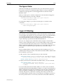
Port Trunking
Port trunking, also known as port bundling or link aggregation, allows a number
of ports to be configured to join together to make a single logical connection of
higher bandwidth. This can be used where a higher performance link is
required, and makes links even more reliable. Port trunking must be
configured on both ends of the link, or network loops may result.
The switch supports static 802.3ad link aggregation, and is also compatible
with third party devices that do not support static 802.3ad link aggregation.
The switch supports up to 6 trunk groups, of up to 8 switch ports each. The two
gigabit Ethernet ports can also be grouped together to form a trunk group. For
trunking to work properly, avoid having a trunk group that spans multiple
switch instances. It is not possible for a trunk group to include both 10/100
Ethernet and gigabit Ethernet ports. Ports in the trunk group do not have to be
contiguous.
To create or destroy port trunk groups on the switch, use the commands:
create switch trunk=trunk [port=port-list] [select={macsrc|
macdest|macboth|ipsrc|ipdest|ipboth}] [speed={10m|100m|
1000m}]
destroy switch trunk=trunk
Port trunk groups can be destroyed on the switch only when no ports belong to
them.
Software Release 2.7.3
C613-03098-00 REV A
Switching
8-9
All the ports in a trunk group must have the same VLAN configuration: they
must belong to the same VLANs and have the same tagging status. All ports in
a trunk group must be added to VLANs together, and can only be deleted from
a VLAN as a group. Similarly, if the tagged or untagged status of the ports is
changed, it must be changed for all ports in the trunk group at the same time.
The members of a trunk group can be specified when it is created, and ports
can be added to or removed from a trunk group by using the commands:
add switch trunk=trunk port=port-list
delete switch trunk=trunk port={port-list|all}
Ports in a trunk group are set to autonegotiate at the trunk speed at full duplex.
When a port is added to a trunk group, the speed setting for the group
overrides the speed setting previously configured for the port. When a port is
removed from a trunk group, the port returns to its previously configured
speed and duplex mode settings.
The speed of the trunk group can either be specified when it is created or set by
using the command:
set switch trunk=trunk [select={macsrc|macdest|macboth|ipsrc|
ipdest|ipboth}] [speed={10m|100m|1000m}]
To display information about trunks on the switch, use the command:
show switch trunk[=trunk]
To display the VLANs to which the ports in the trunk groups belong, use the
command:
show vlan[=all]
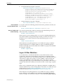
Link Aggregation Control Protocol (LACP)
The implementation of the Link Aggregation Control Protocol (LACP) follows
the IEEE Standard 802.3-2002, CSMA/CD access method and physical layer
specifications.
LACP operates where systems are connected over multiple communications
links. Once LACP has been initially configured and enabled, it automatically
creates trunk groups and assigns appropriate links to their membership. LACP
continues to monitor these groups and dynamically adds or removes links to
them as network changes occur.
LACP achieves this by determining the following:
■
which ports are under LACP control
■
whether each port is in LACP active or LACP passive mode
■
which system has the highest LACP priority
■
the LACP priority of ports
■
whether the periodic timeout is fast or slow
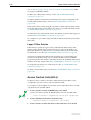
Aggregation criteria
For individual links to be formed into an aggregated group they must meet the
following criteria:
■
Software Release 2.7.3
C613-03098-00 REV A
originate on the same device
8-10
Rapier Switch Software Reference
■
terminate on the same device
■
be members of the same VLANs
■
have the same data rate
■
share the same admin port key (assigned by using the command, add lacp
port command on page 8-71).
The hardware must also be capable and have the capacity to handle the
number of links to be aggregated.
Aggregated group identification
In order to identify particular aggregated groups, each group is assigned a link
aggregation identifier called a lag ID. The lag ID comprises the following
components for both the local system (called the Actor) followed by their
equivalent components for the remote system (called the Partner):
■
system priority - set by the set lacp priority command on page 8-147.
■
system identifier - the MAC address of the system
■
port key - An identifier - created by the LACP software
■
port priority - set by the command, add lacp port command on page 8-71.
■
port number - determined by the device connection
The lag ID can be displayed for each aggregated link by entering the command,
show lacp trunk command on page 8-186
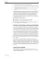
Packet Storm Protection
The packet storm protection feature allows the user to set limits on the
reception rate of broadcast, multicast and destination lookup failure packets.
The software allows separate limits to be set for each port, beyond which each
of the different packet types are discarded. The software also allows separate
limits to be set for each of the packet types. Which of these options can be
implemented depends on the model of switch hardware.
By default, packet storm protection is set to none, that is, disabled. It can be
enabled, and each of the limits can be set using the command:
set switch port=port-list [bclimit={none|limit}]
[dlflimit={none|limit}] [mclimit={none|limit}]
Packet storm protection limits cannot be set for each individual port on the
switch, but can be set for each processing block of ports. The processing blocks
are sets of 8 ports (e.g. as many as are applicable of ports 1-8, 9-16 and 17-24)
and each uplink port is a further processing block. Therefore, a 16-port switch
has four processing blocks and a 24-port switch has five. The two uplink ports
are numbered sequentially after the last port, and therefore are 17 and 18 for a
16-port switch, and 25 and 26 for a 24-port switch. Only one limit can be set per
processing block, and then applies to all three packet types. Thus each of the
packet types are either limited to this value or unlimited (none).
For the Rapier G6 series switches, each port is a processing block, and therefore
packet storm protection limits can be set for each port individually.
The show switch port command displays the packet storm protection settings.
Software Release 2.7.3
C613-03098-00 REV A
Switching
8-11
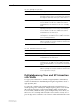
Port Mirroring
Port mirroring allows traffic being received and transmitted on a switch port to
be sent to another switch port, the mirror port, usually to capture data with a
protocol analyser. The mirror port is the only switch port that belongs to no
VLANs, and therefore does not participate in any other switching. Before the
mirror port can be set, it must be removed from all VLANs except the default
VLAN. The port cannot be part of a trunk group. Mirroring four or more ports
may significantly reduce switch performance.
To set a mirror port (and remove it from the default VLAN) use the command:
set switch mirror={none|port}
If another port was previously set as the mirror port, this command returns the
previous mirror port to the default VLAN as an untagged port. Return this port
to any VLANs to which it should belong, by using the add vlan port command,
or set it as a tagged port using the set vlan port command if required.
Either traffic received on a port or traffic transmitted by the port, or both, can
be mirrored. To set a source port whose traffic is to be sent to a mirror port, use
the command:
set switch port={port-list|all} mirror={none|rx|tx|both}
To send packets that match particular criteria to the mirror port, first create a
filter match by using the command:
add switch l3filter match
Then create a filter entry with the action parameter set to sendmirror by using
the command:
add switch l3filter=filter-id entry action=sendmirror.
By default, when mirroring is disabled, no mirror port is set and no source
ports are set to be mirrored. Mirroring functions when a switch mirror port is
set to a valid port. When mirroring is enabled and the switch mirror port is set
to none, then mirroring can be disabled by using the commands:
enable switch mirror
disable switch mirror
The show switch port and show switch commands display the switch and
port mirroring settings.
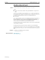
Port Security
The port security feature allows control over the stations connected to each
switch port, by MAC address. If enabled on a port, the switch learns MAC
addresses up to a user-defined limit from 1 to 256, then locks out all other MAC
addresses. One of the following options can be specified for the action taken
when an unknown MAC address is detected on a locked port:
•
Discard the packet and take no further action,
•
Discard the packet and notify management with an SNMP trap,
•
Discard the packet, notify management with an SNMP trap and disable
the port.
To enable port security on a port, set the limit for learned MAC addresses to a
value greater than zero, and specify the action to take for unknown MAC
Software Release 2.7.3
C613-03098-00 REV A
8-12
Rapier Switch Software Reference
addresses on a locked port. To disable port security on a port, set the limit for
learned MAC addresses to zero or none. Port security can be enabled or
disabled on a port by using the command:
set switch port={port-list|all} learn={none|0|1..256}
[intrusionaction={discard|trap|disable}]
If intrusionaction is set to trap or disable, a list of MAC addresses for devices
that are active on a port, but which are not allowed or learned for the port, can
be displayed (Figure 8-46 on page 8-228) by using the command:
show switch port={port-list|all} intrusion
A switch port can be manually locked before it reaches the learning limit by
using the command:
activate switch port={port-list|all} lock
Addresses can be manually added to a port locked list up to a total of 256 MAC
addresses, and the learning limit can be extended to accommodate them. Use
the command:
add switch filter action={forward|discard} destaddress=macadd
port=port [entry=entry] [learn] [vlan={vlan-name|1..4094}]
Learned addresses on locked ports can be saved as part of the switch
configuration, so that they become part of the configuration after a power
cycle. Use the command:
create config=filename
If the configuration is not saved when there is a locked list for a port, the
learning process begins again after the switch is restarted.
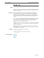
Virtual Local Area Networks (VLANs)
A Virtual LAN (VLAN) is a logical, software-defined subnetwork. It allows
similar devices on the network to be grouped together into one broadcast
domain, irrespective of their physical position in the network. Multiple VLANs
can be used to group workstations, servers, stacks, and other network
equipment connected to the switch, according to similar data and security
requirements.
Decoupling logical broadcast domains from the physical wiring topology
offers several advantages, including the ability to:
■
Move devices and people with minimal, or no, reconfiguration
■
Change a device’s broadcast domain and access to resources without
physically moving the device, by software reconfiguration or by moving its
cable from one switch port to another
■
Isolate parts of the network from other parts by placing them in different
VLANs
■
Share servers and other network resources without losing data isolation or
security
■
Direct broadcast traffic to only those devices that need to receive it thereby
reducing traffic across the network
Software Release 2.7.3
C613-03098-00 REV A
Switching
8-13
■
Connect 802.1q-compatible switches together through one port on each
switch
Devices that are members of the same VLAN exchange data with each other
through the switch’s switching capabilities. To exchange data between devices
in separate VLANs, the switch’s routing capabilities are used. The switch
passes VLAN status information, indicating whether a VLAN is up or down, to
the Internet Protocol (IP) module. IP uses this information to determine route
availability.
The switch has a maximum of 63 VLANs, or 255 for a Rapier i Series switch
ranging from a VLAN identifier (VID) of 1 to 4094.
When the switch is first powered up, a “default” VLAN is created and all ports
are added to it. In this initial unconfigured state, the switch broadcasts all the
packets it receives to the default VLAN. This VLAN has a VID of 1 and an
interface name of vlan1. It cannot be deleted, and ports can be removed from it
only when they also belong to at least one other VLAN. When all devices on
the physical LAN belong to the same logical LAN (same broadcast domain),
the default settings are acceptable and no additional VLAN configuration is
necessary.
Dynamic VLAN Assignment
Dynamic VLAN assignment allows a supplicant to be placed into a specific
VLAN based on information returned from the RADIUS server during
authentication. This limits the network access of a supplicant to a specific
VLAN that is tied to their authentication, and prevents supplicants from
connecting to VLANs for which they are not authorised. A port's VLAN
assignment is determined by the first supplicant to be authenticated on the
port.
VLAN assignment is enabled or disabled using the vlanassignment parameter
of port authentication commands.
The Configured and Actual fields of the show vlan command show which
ports are configured for the VLAN and which have been dynamically assigned
to the VLAN.
Radius attributes
The RADIUS server provides information to the authenticator using RADIUS
tunnel attributes, as defined in RFC 2868, RADIUS Attributes for Tunnel Protocol
Support. The tunnel attributes that must be configured for VLAN assignment
are:
■
Tunnel-Type
The protocol to be used for the tunnel specified by
Tunnel-Private-Group-Id. VLAN (13) is the only supported value.
■
Tunnel-Medium-Type
The transport medium to be used for the tunnel specified by
Tunnel-Private-Group-Id. 802 (6) is the only supported value.
■
Tunnel-Private-Group-ID
The ID of the tunnel the authenticated user should use. This must be the
name or ID number of a VLAN on the switch.
These tunnel attributes are included in the Access-Accept message from the
RADIUS server to the Authenticator.
Software Release 2.7.3
C613-03098-00 REV A
8-14
Rapier Switch Software Reference
Single-host mode
In single host mode, VLAN assignment is as follows:
■
If authentication fails, the supplicant is denied access to the port. The port
is placed in its configured access VLAN, that is, the VLAN it was set up for
in the add vlan command.
■
If the RADIUS server supplies valid VLAN information, the port is placed
in the specified VLAN after configuration.
■
If the RADIUS server supplies invalid VLAN information, the port is
returned to the Unauthorised state, and placed in its configured access
VLAN.
■
If the RADIUS server supplies no VLAN information, the port is placed in
its configured access VLAN after successful authentication.
■
If port authentication is disabled on the port, the port is returned to its
configured access VLAN.
■
When the port is in the Force Authorized, Force Unauthorized or the
Unauthorized state, it is placed in its configured access VLAN.
While the port is in a RADIUS server assigned VLAN, changes to the port's
configured access VLAN do not take effect until the port leaves the assigned
VLAN. This can occur if:
Multi-supplicant mode
■
the last authentication session on the port expires
■
the link goes down
■
port authentication is disabled on the port
■
port authentication is disabled on the system
VLAN assignment can be run in multi-supplicant mode, if the multi-supplicant
mode is enabled. In multi-supplicant mode, the behaviour is dictated by which
supplicant is authenticated first.
If the multi-supplicant mode is enabled on a port authentication port, the
behaviour of the first authenticated supplicant is the same as that of a
supplicant in single-supplicant mode. For all further supplicants, the
securevlan parameter specifies the action that is taken when authenticating
any supplicants after the first supplicant has authenticated. There are two
possible actions:
■
securevlan=on
Only those supplicants with a VLAN that is the same as that of the first
authenticated supplicant are authenticated. This is the default, and is the
more secure action.
■
securevlan=off
All further authenticated supplicants are placed in the same VLAN as the
first authenticated supplicant. This action is less secure.
802.1x Guest VLAN
802.1x ports can be configured with a limited access guest VLAN, which is
used when no 802.1x host is currently attached to the port. This limited access
VLAN is defined using the guestvlan parameter.
As soon as a single 802.1x packet is received on the port, it is removed from the
guest VLAN, and put into its configured access VLAN in the Unauthenticated
Software Release 2.7.3
C613-03098-00 REV A
Switching
8-15
state. This effectively disables the guest VLAN on the port until the port’s link
goes down.
A guest VLAN can only be configured for a port that is running in singlesupplicant mode.
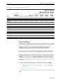
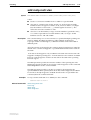
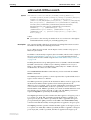
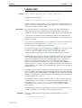
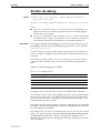
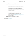
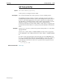
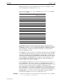
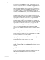
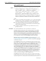
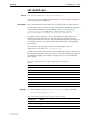
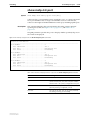
VLAN Tagging
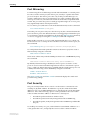
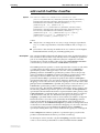
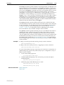
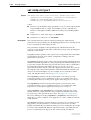
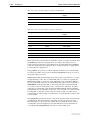
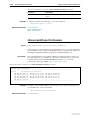
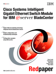
An Ethernet packet can contain a VLAN tag with fields that specify VLAN
membership and user priority. The VLAN tag is described in IEEE
Standard 802.3ac, and is four octets that can be inserted between the Source
Address and the Type/Length fields in the Ethernet packet (Figure 8-1 on
page 8-16). To accommodate the tag, IEEE Standard 802.3ac also increased the
maximum allowable length for an Ethernet frame to 1522 octets (the minimum
size is 64 octets). IEEE Standard 802.1q specifies how the data in the VLAN tag
switches frames. VLAN-aware devices are able to add the VLAN tag to the
packet header. VLAN-unaware devices cannot set or read the VLAN tag.
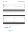
Table 8-2 on page 8-15 lists the meaning and use of the fields in the Ethernet
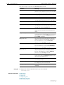
frame. Figure 8-1 on page 8-16 shows the format of VLAN data in an Ethernet
frame. Twelve bits of the tag are the VLAN Identifier (VID), which indicates the
VLAN to which the packet belongs. Table 8-3 on page 8-16 lists the VLAN
Identifier values that have specific meaning.
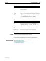
Table 8-2: Fields in the Ethernet frame for QoS and VLAN switching
Software Release 2.7.3
C613-03098-00 REV A
Field
Length
Meaning and use
TPID
2 octets
The Tag Protocol Identifier (TPID) is defined by IEEE
Standard 802.1q as 0x81-00.
User Priority
3 bits
The User Priority field is the priority tag for the frame, which
can be used by the switch to determine the Quality of
Service to apply to the frame. The three bit binary number
represents eight priority levels, 0 to 7.
CFI
1 bit
The Canonical Format Indicator (CFI flag) indicates whether
all MAC address information that may be present in the
MAC data carried by the frame is in canonical format.
VID
12 bits
The VLAN Identifier (VID) field uniquely identifies the VLAN
to which the frame belongs.
8-16
Rapier Switch Software Reference
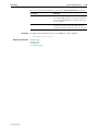
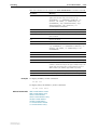
Figure 8-1: Format of user priority and VLAN data in an Ethernet frame
Destination
Address
64 bits
48 bits
TPID
16 bits
Source Type/
Address Length Frame Data
48 bits
16
bits
User
Priority CFI
3 bits
1 bit
Preamble
368-12000
CRC
32 bits
VID
12 bits
0x81-00
SWITCH6
Table 8-3: Reserved VID values
VID value (hexadecimal) Meaning and use of reserved VID values
0
The null VLAN ID. Indicates that the tag header contains only
user priority information; no VLAN Identifier is present in the
frame. This VID value must not be configured in any forwarding
database entry, or used in any management operation. Frames
that contain the null VLAN ID are also known as priority-tagged
frames.
1
The default VID value used for classifying frames on ingress
through an untagged switch port.
FFF
Reserved for implementation use. This VID value must not be
configured in any forwarding database entry, used in any
management operation, or transmitted in a tag header.
Ethernet packets that contain a VLAN tag are referred to as tagged frames, and
switch ports that transmit tagged frames are referred to as tagged ports.
Ethernet packets that do not contain a VLAN tag are referred to as untagged
frames, and switch ports that transmit untagged frames are referred to as
untagged ports. VLANs can consist of simple logical groupings of untagged
ports in which the ports receive and transmit untagged packets. Alternatively,
VLANs can contain only tagged ports or a mixture of tagged and untagged
ports.
The switch is VLAN-aware. It can accept VLAN tagged frames, and supports
the VLAN switching required by such tags. A network can contain a mixture of
VLAN-aware devices, for example, other 802.1q-compatible switches, and
VLAN-unaware devices, for example, workstations and legacy switches that
do not support VLAN tagging. The switch can be configured to send VLAN
tagged or untagged frames on each port, depending on whether the devices
connected to the port are VLAN-aware. By assigning a port to two different
VLANs, to one as an untagged port and to another as a tagged port, it is
possible for the port to transmit both VLAN-tagged and untagged frames. A
port must belong to a VLAN at all times unless the port has been set as the
mirror port for the switch.
Every frame admitted by the switch has a VID associated with it. When a frame
arrives on a tagged port, the associated VID is determined from the VLAN tag
the frame had when it arrived. When a frame arrives on an untagged port, it is
Software Release 2.7.3
C613-03098-00 REV A
Switching
8-17
associated with the VID of the VLAN for which the incoming port is untagged.
When the switch forwards a frame over a tagged port, it adds a VLAN tag to
the frame. When the switch forwards the frame over an untagged port, it
transmits the frame as a VLAN-untagged frame, not including the VID in the
frame.
The VLAN tag that the switch adds to a frame on egress depends on whether
the frame is switched in Layer 2 or Layer 3. In Layer 3 switching, the switch
determines the destination VLAN from its routing tables. The VID of the
destination VLAN is added to the frame on egress. In Layer 2 switching, the
frame’s source and destination VLANs are the same. The VID that was
associated with the frame on ingress is associated with it on egress.
VLAN membership using VLAN tags
Ports can belong to many VLANs as tagged ports. Because VLAN tags
determine to which VLAN a packet belongs, it is easy to:
•
Share network resources, such as servers and printers, across several
VLANs
•
Configure VLANs that span several switches
For tagged ports, the switch uses the VID of incoming frames, and the frame’s
destination field to switch traffic through a VLAN aware network. Frames are
transmitted only on ports belonging to the required VLAN. Other vendors’
VLAN-aware devices on the network can be configured to accept traffic from
one or more VLANs. A VLAN-aware server can be configured to accept traffic
from many different VLANs, and then return data to each VLAN without
mixing or leaking data into the wrong VLANs.
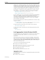
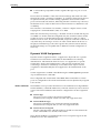
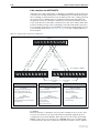
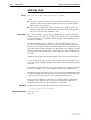
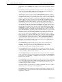
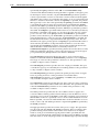
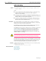
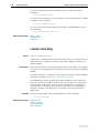
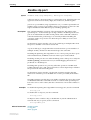
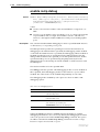
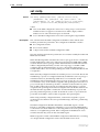
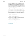
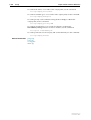
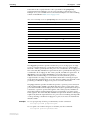
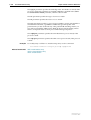
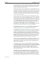
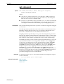
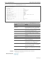
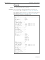
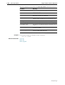
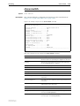
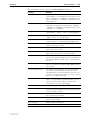
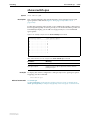
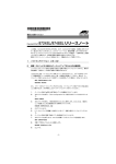
Figure 8-2 on page 8-18 shows a network configured with VLAN tagging.
Table 8-4 on page 8-18 shows the VLAN membership. The server on port 2 on
Switch A belongs to both the admin and marketing VLANs. The two switches
are connected through uplink port 26 on Switch A and uplink port 25 on
Switch B, which belong to both the marketing VLAN and the training VLAN, so
devices on both VLANs can use this link.
Software Release 2.7.3
C613-03098-00 REV A
8-18
Rapier Switch Software Reference
Figure 8-2: VLANs with tagged ports
Training VLAN VID=3
Port 3
Port 22
Port 21
Port 26
Switch A
Switch B
Port 25
Port 1
Port 4
Port 2
Port 23
Admin VLAN VID=2
Marketing VLAN VID=4
411
VLAN-aware
server
SWITCH3
Table 8-4: VLAN membership of example of a network using tagged ports
VLAN
Member ports
Training
3, 26 on Switch A
21, 22, 25 on Switch B
Marketing
2, 4, 26 on Switch A
23, 25 on Switch B
Admin
1, 2 on Switch A
VLAN Membership of Untagged Packets
A VLAN that does not send VLAN-tagged frames is a logical grouping of
ports. All untagged traffic arriving at those ports belongs to that VLAN.
VLANs based on untagged ports are limited because each port can belong only
to one VLAN as an untagged port. Limitations include:
•
It is difficult to share network resources, such as servers and printers,
across several VLANs. The routing functions in the switch must be
configured to interconnect using untagged ports only.
•
A VLAN that spans several switches requires a port on each switch for
the interconnection of the various parts of the VLAN. When there are
several VLANs in the switch that span more than one switch, then
many ports are occupied with connecting the VLANs, and so are
unavailable for other devices.
Software Release 2.7.3
C613-03098-00 REV A
Switching
8-19
If the network includes VLANs that do not need to share network resources or
span several switches, VLAN membership can usefully be based on untagged
ports. Otherwise, VLAN membership should be determined by tagging (see
“VLAN Tagging” on page 8-15).
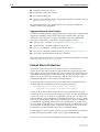
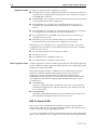
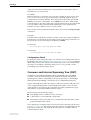
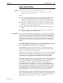
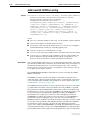
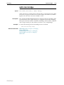
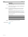
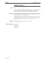
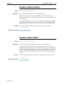
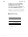
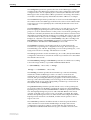
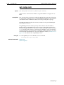
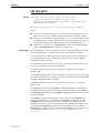
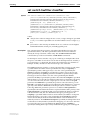
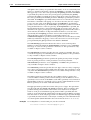
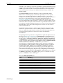
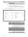
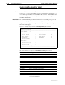
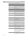
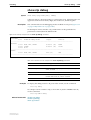
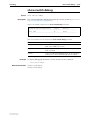
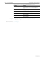
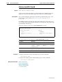
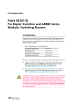
Figure 8-3 on page 8-19 shows two port-based VLANs with untagged ports.
Ports 1-3 belong to the marketing VLAN, and ports 14-16 belong to the training
VLAN. The switch acts as two separate bridges: one that forwards traffic
between the ports belonging to the marketing VLAN, and a second one that
forwards traffic between the ports belonging to the training VLAN. Devices in
the marketing VLAN can communicate with devices in the training VLAN only
by using the switch’s routing functions.
Figure 8-3: VLANs with untagged ports
Port 1
Port 2
Port 3
Marketing VLAN
Switch
Training VLAN
Port 14
Port 15
Port 16
411
SWITCH2
Creating VLANs
To summarise the process:
1.
Create the VLAN.
2.
Add tagged ports to the VLAN, if required.
3.
Add untagged ports to the VLAN, if required.
To create a VLAN, use the command:
create vlan=vlan-name vid=2..4094
Every port must belong to a VLAN unless it is the mirror port. By default, all
ports belong to the default VLAN as untagged ports.
Software Release 2.7.3
C613-03098-00 REV A
8-20
Rapier Switch Software Reference
To add tagged ports to a VLAN, use the command:
add vlan={vlan-name|1..4094} port={port-list|all}
frame=tagged
A port can be tagged for any number of VLANs.
To add untagged ports to a VLAN, use the command:
add vlan={vlan-name|1..4094} port={port-list|all}
[frame=untagged]
A port can be untagged for zero or one VLAN. A port can be added only to the
default VLAN as an untagged port when it is not untagged for another VLAN.
A port cannot transmit both tagged and untagged frames for the same VLAN
(that is, it cannot be added to a VLAN as both a tagged and an untagged port).
To remove ports from a VLAN, use the command:
delete vlan={vlan-name|1..4094} port={port-list|all}
Removing an untagged port from a VLAN returns it to the default VLAN
unless it is a tagged port for another static VLAN. An untagged port can be
deleted from the default VLAN only when the port is a tagged port for another
static VLAN.
Ports tagged for some VLANs and left in the default VLAN as untagged ports
transmit broadcast traffic for the default VLAN. If this is not required, the
unnecessary traffic in the switch can be reduced by deleting those ports from
the default VLAN.
To change the tagging status of a port in a VLAN, use the command:
set vlan={vlan-name|1..4094} port={port-list|all}
frame=tagged
To destroy a VLAN, use the command:
destroy vlan={vlan-name|2..4094|all}
VLANs can be destroyed only when no ports belong to them.
To display the VLANs configured on the switch, use the command:
show vlan[={vlan-name|1..4094|all}]
Information that may be useful for troubleshooting a network can be displayed
with the VLAN debugging mode. This is disabled by default, and can be
enabled for a specified time, disabled, and displayed using the commands:
enable vlan={vlan-name|1..4094|all} debug={pkt|all}
[output=console] [timeout={1..4000000000|none}]
disable vlan={vlan-name|1..4094|all} debug={pkt|all}
show vlan debug
To view packet reception and transmission counters for a VLAN, use the
command (see the Interfaces chapter of the switch’s Software Reference):
show interface=vlann counter
Software Release 2.7.3
C613-03098-00 REV A
Switching
8-21
Summary of VLAN Tagging Rules
When designing a VLAN and adding ports to VLANs, consider the following
rules:
•
Except for the mirror port, each port must belong to at least one static
VLAN. By default, a port is an untagged member of the default VLAN.
•
A port can be untagged for zero or one VLAN. A port that is untagged
for a VLAN transmits frames destined for that VLAN without a VLAN
tag in the Ethernet frame.
•
A port can be tagged for zero or more VLANs. A port that is tagged for
a VLAN transmits frames destined for that VLAN with a VLAN tag,
including the numerical VLAN Identifier of the VLAN.
•
A port cannot be untagged and tagged for the same VLAN.
•
The mirror port, if present, is not a member of any VLAN.
VLAN Interaction with Trunk Groups
All the ports in a trunk group must have the same VLAN configuration. They
must belong to the same VLANs and have the same tagging status; and they
must be operated on as a group.
Static and Dynamic VLANs
All VLANs created by the user on the command line are static VLANs. The
default VLAN is also a static VLAN. A port must belong to at least one static
VLAN.
Dynamic VLANs are created by GVRP, a GARP application whose purpose is
to propagate VLAN information between VLAN aware switches (see the
Generic Attribute Registration Protocol (GARP) chapter). These dynamic VLANs
are entitled gvrpxxx, where xxx is the VLAN’s VLAN Identifier. Dynamic
VLANs are created only when GVRP is enabled on the switch. GVRP is
disabled by default.
All static VLANs except for the default VLAN can be destroyed by the user.
Dynamic VLANs cannot be directly destroyed by the user, but may be
destroyed according to the operations of GVRP by using the reset garp
command on page 9-15 of Chapter 9, Generic Attribute Registration Protocol
(GARP) or by disabling the GVRP instance.
A user can add, delete, or modify ports for a static VLAN, but not for a
dynamic VLAN. Dynamic VLANs created by GVRP include only tagged ports.
Software Release 2.7.3
C613-03098-00 REV A
8-22
Rapier Switch Software Reference
Protected VLANs
If a VLAN is protected, Layer 2 traffic between ports that are members of a
protected VLAN is blocked. Traffic can be Layer 3 switched to another VLAN.
This feature prevents members of a protected VLAN from communicating with
each other yet still allows members to access another network. Layer 3 Routing
between ports in a protected VLAN can be prevented by adding a Layer 3
filter. The protected VLAN feature also allows all of the members of the
protected VLAN to be in the same subnet.
A typical application is a hotel installation where each room has a port that can
be used to access the Internet. In this situation it is undesirable to allow
communication between rooms.
To create a protected VLAN, use the create vlan command on page 8-95 with
the protected parameter.
Private VLANs
A private VLAN contains switch ports that are isolated from other ports in the
VLAN, but can access another network through an uplink port or uplink trunk
group. These ports are called private ports. Private ports may be standalone or
be combined into groups. Standalone private ports can only communicate with
the uplink port, not with other ports in the VLAN. Private ports that are in a
group can communicate with other ports in the group and with the uplink
port, but cannot communicate with the other private ports in the VLAN.
The switch forwards traffic between private ports and the uplink port, and
between private ports within a group, according to its normal forwarding
rules. The only difference is that forwarding to other private ports is blocked
unless the ports are in the same group. Note that all traffic between private
ports is blocked, not only Layer 2 traffic.
A typical application is a hotel installation where each room has a port that can
access the Internet. In this situation it is undesirable to allow communication
between rooms. Another application is to simplify IP address assignment.
Ports can be isolated from each other while belonging to the same subnet.
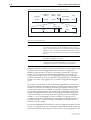
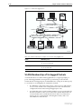
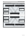
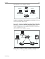
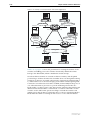
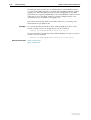
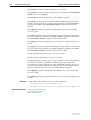
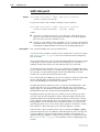
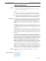
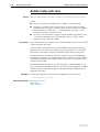
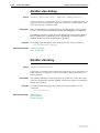
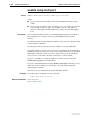
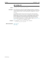
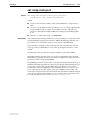
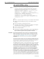
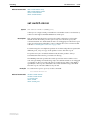
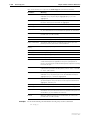
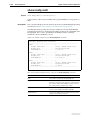
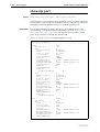
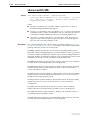
Figure 8-4 on page 8-23 shows an example of a network using private VLANs.
In this scenario, two service providers are each providing multiple services
through multiple VLANs over separate uplinks. Customers are subscribed to
services from one or both service providers. Each customer’s ports are isolated
from other customers, but communicate with the ISP or ISPs through the
appropriate uplink port. A single customer may use multiple ports, connected
to individual PCs or trunked together to increase bandwidth. If a customer
uses multiple ports, these ports are able to communicate with each other.
Software Release 2.7.3
C613-03098-00 REV A
Switching
8-23
Figure 8-4: Example network configuration using private VLANs
ISP 1
ISP 2
VLANs 2 and 3
VLANs 11 and 12
Uplink
(trunk group)
Uplink
17
18
19
20
21
22
23
24
1
2
3
4
5
6
7
8
private
port
private
port
private group
(may be a
trunk group)
Customer 1
VLAN 12
ISP 2
25
Customer 3
Customer 2
VLANs 2 and 3
ISP 1
VLANs 2, 3 and 11
ISPs 1 and 2
private-vlan
Membership Rules for Private VLANs
Each private VLAN:
•
Must contain one uplink port or uplink trunk group
•
May contain multiple private ports
•
Cannot contain any non-private ports
•
Cannot be the Default VLAN (vlan1)
Each private port:
•
Can be a member of multiple private VLANs
•
Cannot be a private port in some VLANs and a non-private port in
other VLANs
•
Cannot be an uplink port in another VLAN
Each uplink port:
•
Can be a member of multiple private VLANs
•
Cannot be a member of both private and non-private VLANs
Each private or uplink port:
Software Release 2.7.3
C613-03098-00 REV A
•
May be tagged or untagged but can only be an untagged member of one
port-based VLAN
•
May be trunked with other ports of the same type
8-24
Rapier Switch Software Reference
Private VLANs on Rapier 48i Switches
The ports on Rapier 48i switches are divided into two instances:
•
ports 1-24 plus uplink port 49
•
ports 25-48 plus uplink port 50
Private VLANs on a Rapier 48i switch can consist of only ports from one
instance. Both the private ports and the uplink port must be in the same
instance.
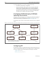
Configuring Private VLANs
To create a private VLAN and add ports to it:
1.
Create the VLAN
To create a VLAN and specify that it is private, use the command:
create vlan=vlan-name vid=2..4094 private
2.
Add the uplink port or trunk group
To add the uplink to a private VLAN, use one of the commands:
add vlan={vlan-name|1..4094} port=port-list
[frame={untagged|tagged}] uplink
where port-list is either a single port number for a single uplink port, or a
list of port numbers for a trunk group. If you are adding a trunk group to
the VLAN as an uplink, the ports must already be trunked together, and
you must specify all the ports.
3.
Add the private ports
To add a private port or ports to a private VLAN, use one of the
commands:
add vlan={vlan-name|1..4094} port={port-list|all}
[frame={untagged|tagged}] [group]
The group parameter specifies that the listed ports may communicate with
each other, but not with any other private ports in the VLAN.
4.
Delete ports from a private VLAN as necessary
To delete private ports from a private VLAN, use one of the commands:
delete vlan={vlan-name|1..4094} port=port-list
delete vlan={vlan-name|1..4094} port=all
A private VLAN cannot contain private ports when an uplink is deleted
from the VLAN, because a private VLAN must always have an uplink. To
delete the uplink port or ports and any private ports from a private VLAN,
use the port=all option in the above command.
If the port is a member of a private group, you must delete all ports in the
group at once. This stops groups from having different member ports in
different VLANs.
Software Release 2.7.3
C613-03098-00 REV A
Switching
8-25
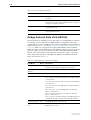
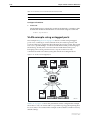
VLAN Relaying
VLAN relaying allows the passage of traffic between the VLANs on one
switch, for protocols that are not processed by the switch’s routing functions.
Particular protocols or protocol groups can be specified, and filtering occurs on
the basis of protocol identification number. VLAN relaying is similar to the
bridging function of an Allied Telesyn router.
Protocol names have been predefined for many protocol types. Those protocols
that are transferred by VLAN relay and that have predefined names are given
in Table 8-5 on page 8-25, with their associated protocol identification numbers.
Other protocols can be specified by entering their protocol identification
numbers. Protocols that are routed by the switch, including IP, IPX, AppleTalk,
STP, and GARP, cannot be VLAN relayed.
Table 8-5: Predefined protocol types implemented by VLAN relay
Software Release 2.7.3
C613-03098-00 REV A
Protocol Name
Protocol Number
Encapsulation
All802
all SAP protocols
SAP
Netbeui
F0
SAP
SNA Path Control
04
SAP
PROWAY-LAN
0E
SAP
EIA-RS
4E
SAP
PROWAY
8E
SAP
ISO CLNS IS
FE
SAP
AllEthII
all EthII protocols
EthII
XEROX PUP
0200
EthII
PUP Addr Trans
0201
EthII
XEROX NS IDP
0600
EthII
X.75 Internet
0801
EthII
NBS Internet
0802
EthII
ECMA Internet
0803
EthII
Chaosnet
0804
EthII
X.25 Level 3
0805
EthII
XNS Compat
0807
EthII
Banyan Systems
0BAD
EthII
BBN Simnet
5208
EthII
DEC MOP Dump/Ld
6001
EthII
DEC MOP Rem Cons
6002
EthII
DEC LAT
6004
EthII
DEC Diagnostic
6005
EthII
DEC Customer
6006
EthII
DEC LAVC
6007
EthII
RARP
8035
EthII
DEC LANBridge
8038
EthII
DEC Encryption
803D
EthII
8-26
Rapier Switch Software Reference
Table 8-5: Predefined protocol types implemented by VLAN relay (Continued)
Protocol Name
Protocol Number
Encapsulation
IBM SNA
80D5
EthII
SNMP
814C
EthII
AllSNAP
all SNAP protocols
SNAP
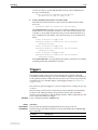
VLAN relaying operates in the following stages:
1.
The user creates one or more VLAN relay entities and adds the required
VLANs and protocols to each entity.
2.
The VLAN relay entity attaches to each specified VLAN and receives traffic.
If more than one VLAN relay entity is attached to the same VLAN for the
same protocol type, an intermediate attachment level receives the packet,
duplicates it, and sends it to separate VLAN relay entities as required.
3.
The VLAN relay entity sends the packet to the appropriate destination
VLAN. Destination addresses are determined from the switch’s learned
address tables. If the destination address cannot be found, the packet is sent
to all ports on all VLANs that are part of the VLAN relay entity. If the packet
is destined for the VLAN on which it was received, the relaying entity does
not send it to that VLAN because the packet causes a destination lookup
failure, and the switch itself sends the packet to all ports in the VLAN.
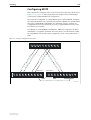
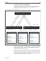
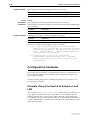
Configuring VLAN Relaying
To configure VLAN relaying on the switch, first create a VLAN relay entity and
give it a unique name, using the command:
create vlanrelay=name
An existing VLAN relay entity can be disabled or destroyed using the
commands:
disable vlanrelay=name
destroy vlanrelay=name
In many networks, only one VLAN relay entity is required. The following
configurations are examples of situations when more than one VLAN relay
entity is used.
•
If a number of protocols and VLANs are part of VLAN relaying but not
all protocols on all VLANs, then setting up a number of VLAN relay
entities allows only relevant protocols and VLANs to be part of
relaying.
•
If traffic is to be relayed between certain VLANs but not others (for
example, between VLAN 1 and VLAN 2, and between VLAN 1 and
VLAN 3, but not between VLAN 2 and VLAN 3), then separate VLAN
relay entities are required.
To initiate relaying, add the VLANs which packets are to be sent between, and
the desired protocols, to the VLAN relay entity, by using the command:
add vlanrelay=name [protocol=protocoltype] [vlan={vlan-name|
1..4094}]
Software Release 2.7.3
C613-03098-00 REV A
Switching
8-27
Protocols are specified by protocol type and number, or by allowing all
protocols of a certain type. A predefined list of common protocols is provided
in Table 8-5 on page 8-25.
VLANs and/or protocols can be removed from an existing VLAN relay entity
by using the command:
delete vlanrelay=name [protocol=protocoltype] vlan=[{vlanname|1..4094}]
A count of the packets relayed by the VLAN relay entity or entities, which
shows the packets relayed from and to each VLAN, can be displayed by using
the command:
show vlanrelay[=name]
The traffic being relayed, including the source and destination VLANs and the
relevant VLAN relay entity, can be displayed by using the command:
enable vlanrelay debug
VLAN relay debugging can be disabled by using the command:
disable vlanrelay debug
Debugging is disabled by default. It can be enabled for one specified VLAN
relay entity, and can be disabled for all entities or for a specified entity.
The Layer 2 Switching Process
The Layer 2 switching process comprises related but separate processes:
■
The Ingress Rules
■
The Learning Process
■
The Forwarding Process
■
The Egress Rules
Ingress rules admit or discard frames based on their VLAN tagging.
The Learning process learns the MAC addresses and VLAN membership of
frames admitted on each port.
The Forwarding process determines to which ports the frames are forwarded,
and the Quality of Service priority with which they are transmitted.
Finally, Egress rules determine for each frame whether VLAN tags are included
in the Ethernet frames that are transmitted. These processes assume that each
station on the extended LAN has a unique data link layer address, and that all
data link layer frames have a header that includes the source (sender’s) MAC
address and destination (recipient’s) MAC address.
Software Release 2.7.3
C613-03098-00 REV A
8-28
Rapier Switch Software Reference
The Ingress Rules
When a frame first arrives at a port, ingress rules for the port check the VLAN
tagging in the frame to determine whether to discard it or forward it to the
learning process.
The first check depends on whether the Acceptable Frame Types parameter is
set to Admit All Frames or to Admit Only VLAN Tagged Frames. A port that
transmits only VLAN tagged frames is automatically set to Admit Only VLAN
Tagged Frames regardless of the VLAN to which the port belongs. The user
cannot change this setting. Frames with a null numerical VLAN Identifier
(VID) are VLAN-untagged frames or frames with priority tagging only.
Every frame received by the switch must be associated with a VLAN. When a
frame is admitted by the Acceptable Frame Types parameter, the second part of
the Ingress Rules associates each untagged frame admitted with the VID of the
VLAN for which the port is untagged.
Every port belongs to one or more VLANs so every incoming frame has a VID
that shows to which VLAN it belongs. The final part of the Ingress Rules
depends on whether Ingress Filtering is enabled for the port. If Ingress Filtering
is disabled, all frames are passed on to the Learning Process, regardless of
which VLAN they belong to. If Ingress Filtering is enabled, frames are
admitted only when they have the VID of a VLAN to which the port belongs.
Otherwise, they are discarded.
The default settings for the Ingress Rules are to Admit All Frames, and for
Ingress Filtering to be off. This means that if no VLAN configuration has been
done, all incoming frames pass to the learning process, regardless of whether
not they are VLAN tagged. The parameters for each port’s ingress rules can be
configured by using the command:
set switch port={port-list|all} [acceptable={vlan|all}]
[infiltering={on|off}]
The Learning Process
The learning process uses an adaptive learning algorithm, sometimes called
backward learning, to discover the location of each station on the extended LAN.
All frames admitted by the Ingress Rules on any port are passed on to the
Forwarding Process if they are for destinations within the same VLAN. Frames
destined for other VLANs are passed to the layer three protocol, for instance IP.
For every frame admitted, the frame’s source MAC address and numerical
VLAN Identifier (VID) are compared with entries in the forwarding database
for the VLAN (also known as a MAC address table, or a forwarding table)
maintained by the switch. The forwarding database contains one entry for
every unique station MAC address the switch knows in each VLAN.
If the frame’s source address is not already in the forwarding database for the
VLAN, the address is added and an ageing timer for that entry is started. If the
frame’s source address is already in the forwarding database, the ageing timer
for that entry is restarted. Switch learning is enabled by default; it can be
disabled or enabled by using the commands:
DISable SWItch LEarning
ENAble SWItch LEarning
Software Release 2.7.3
C613-03098-00 REV A
Switching
8-29
If the ageing timer for an entry in the forwarding database expires before
another frame with the same source address is received, the entry is removed
from the forwarding database. This prevents the forwarding database from
being filled up with information about stations that are inactive or have been
disconnected from the network, while ensuring that entries for active stations
are kept alive in the forwarding database. The ageing timer is enabled by
default; it can be disabled or enabled by using the commands:
ENAble SWItch AGEingtimer
DISable SWItch AGEingtimer
If switch learning is disabled and the ageing timer has aged out all dynamically
learned filter entries, only statically entered MAC source addresses are used to
decide which packets to forward or discard. If the switch finds no matching
entries in the forwarding database during the Forwarding Process, then all
switch ports in the VLAN are flooded with the packet, except the port on
which the packet was received.
The default of the ageing timer is 300 seconds (5 minutes) but can be modified
by using the command:
SET SWItch AGEingtimer=10..1000000
The forwarding database relates a station’s (source) address to a port on the
switch, and is used by the switch to determine from which port to transmit
frames with a destination MAC address matching the entry in the station map.
To display the contents of the forwarding database, use the command:
show switch fdb [address=macadd] [discard={source|
destination}] [hit={yes|no}] [l3={yes|no}]
[port={portlist|all}] [status={static|dynamic}]
[vlan={vlan-name|1..4094}]
To display general switch settings, including settings for switch learning and
the switch ageing timer, use the command:
show switch
The Forwarding Process
The forwarding process forwards received frames that are to be relayed to
other ports in the same VLAN, filtering out frames on the basis of information
contained in the station map and on the state of the ports. When a frame is
received on the port for a destination in a different VLAN, it is either Layer 3
switched if it is an IP packet, or looked up in the Layer 3 routing tables.
Forwarding occurs only when the port on which the frame was received is in
the Spanning Tree forwarding or disabled states. The destination address is
then looked up in the forwarding database for the VLAN. If the destination
address is not found, the switch floods the frame on all ports in the VLAN
except the port on which the frame was received. If the destination address is
found, the switch discards the frame if the port is not in the STP forwarding or
disabled states, if the destination address is on the same port as the source
address, or if there is a static filter entry for the destination address set to
discard (see “Layer 2 Filtering” on page 8-31). Otherwise, the frame is
forwarded on the indicated port.
This whole process can further be modified by the action of static switch filters.
These are configurable filters that allow switched frames to be checked against
a number of entries.
Software Release 2.7.3
C613-03098-00 REV A
8-30
Rapier Switch Software Reference
The forwarding process provides storage for queued frames to be transmitted
over a particular port or ports. More than one transmission queue may be
provided for a given port. The transmission queue where a frame is sent is
determined by the user priority tag in the Ethernet frame and the Quality of
Service mapping (see “Quality of Service” on page 8-30).
Quality of Service
The switch hardware has a number of Quality of Service (QOS) egress queues
that can be used to give priority to the transmission of some frames over other
frames on the basis of their user priority tagging. The user priority field in an
incoming frame (with value 0 to 7) determines which of the eight priority levels
the frame is allocated. When a frame is forwarded, it is sent to a QOS egress
queue on the port determined by the mapping of priority levels to QOS egress
queues. All frames in the first QOS queue are sent before frames in the second
QOS egress queue, and so on, until frames in the last QOS egress queue, which
are sent when there are no frames waiting to be sent in any of the higher QOS
egress queues.
The mapping between user priority and a QOS egress queue can be configured
by using the command:
SET SWItch QOS=P0,P1,P2,P3,P4,P5,P6,P7
The switch has four QOS egress queues. It has a default mapping of priority
levels to QOS egress queues as defined in IEEE Standard 802.1q (Table 8-35 on
page 8-179).
Table 8-6: Default priority level to queue mapping for four QOS egress queues
Priority level
QOS Egress Queue
0
1
1
0
2
0
3
1
4
2
5
2
6
3
7
3
To display the mapping of user priority to QOS egress queues, use the
command:
show switch qos
The QoS commands described in Chapter 35, Quality of Service (QoS) on
Switch Ports are available on Rapier i Series models only.
Software Release 2.7.3
C613-03098-00 REV A
Switching
8-31
The Egress Rules
After the forwarding process determines the ports and transmission queues
from which a frame is forwarded, the Egress Rules for each port determine
whether the outgoing frame is VLAN-tagged with its numerical VLAN
Identifier (VID).
When you add a port to a VLAN, configure it to transmit either untagged or
VLAN tagged packets by using the command:
add vlan={vlan-name|1..4094} port={port-list|all}
[frame={tagged|untagged}]
To change this setting for a port that is already part of a VLAN, use the
command:
set vlan={vlan-name|1..4094} port={port-list|all}
frame={untagged|tagged}
Layer 2 Filtering
The switch has a forwarding database, entries that determine whether frames
are forwarded or discarded over each port. Entries in this forwarding database
are created dynamically by the learning process. A dynamic entry is
automatically deleted from the Forwarding Database when its ageing timer
expires. Filtering is specified in the IEEE Standard 802.1d.
The user can configure static switch filter entries using the command line
interface. Static switch filter entries associate a MAC address with a VLAN and
a port in the VLAN. When the switch receives a frame with a destination
address and VLAN Identifier that match those of a static filter entry, the frame
can be either forwarded to the port specified in the static filter entry, or
discarded.
The forwarding database supports queries by the forwarding process as to
whether frames with given values of the destination MAC address field should
be forwarded to a given port.
To add or delete a static switch filter entry, use the command:
add switch filter action={forward|discard} destaddress=macadd
port=port [entry=entry] [learn] [vlan={vlan-name|1..4094}]
delete switch filter port=port entry=entry-list
To display current static and learned switch filter entries, use the command:
show switch filter [port={port-list|all}]
[destaddress=macadd] [entry=entrylist] [vlan={vlan-name|
1..4094}]
For each VLAN, the destination MAC address of a frame to be forwarded is
checked against the forwarding database. If there is no entry for the destination
address and VLAN, the frame is transmitted on all ports in the VLAN that are
in the forwarding or disabled states, except the port on which the frame was
received. This process is referred to as flooding. If an entry is found in the
forwarding database, but the entry is not marked as forwarding or it points to
the same port the frame was received on, the frame is discarded. Otherwise,
Software Release 2.7.3
C613-03098-00 REV A
8-32
Rapier Switch Software Reference
the frame is transmitted on the port specified by the entry in the forwarding
database.
Spanning Tree Protocol (STP)
The Spanning Tree Protocol (STP) automatically disables redundant paths in a
network to avoid loops, and enables them when a fault in the network means
they are needed to keep traffic flowing.
A sequence of LANs and switches may be connected together in an arbitrary
physical topology resulting in more than one path between any two switches.
If a loop exists, frames transmitted onto the extended LAN would circulate
around the loop indefinitely, decreasing the performance of the extended LAN.
On the other hand, multiple paths through the extended LAN provide the
opportunity for redundancy and backup in the event of a bridge experiencing a
fatal error condition. The spanning tree is created through the exchange of
Bridge Protocol Data Units (BPDUs) between the bridges in the LAN when
they start up, or when a change in the configuration of the network is detected.
The spanning tree algorithm ensures that the extended LAN contains no loops
and that all LANs are connected by:
■
Detecting the presence of loops and automatically computing a logical
loop-free portion of the topology, called a spanning tree. The topology is
dynamically pruned to a spanning tree by declaring the ports on a switch
redundant, and placing the ports into a ‘Blocking’ state.
■
Automatically recovering from a switch failure that would partition the
extended LAN by reconfiguring the spanning tree to use redundant paths,
if available.
The logical tree computed by the spanning tree algorithm has the following
properties:
■
A single switch, called the root bridge, forms a unique root to the tree. The
root bridge is the bridge with the lowest Bridge ID. Each switch in an
extended LAN is uniquely identified by its Bridge ID, which comprises the
switch’s root priority (a spanning tree parameter) and its MAC address.
■
Each switch or LAN in the tree, except the root bridge, has a unique parent,
known as the designated bridge. Each LAN has a single switch, called the
designated bridge, that logically connects the LAN to which the switch is
attached, to the next LAN closer to the root bridge.
■
Each port connecting a switch to a LAN has an associated cost. The root path
cost is the sum of the costs for each port between the switch and the root
bridge. The designated bridge for a LAN is the switch on the LAN with the
lowest root path cost, and therefore logically closer to the root bridge. If
two switches on the same LAN have the same lowest root path cost, the
switch with the lowest bridge ID is elected the designated bridge.
The spanning tree computation is a continuous, distributed process. The
algorithm uses the following process to establish the spanning tree:
1.
A unique root bridge is elected by the switches in the LAN.
2.
A designated bridge is elected for each LAN in the extended LAN by the
switches in the LAN.
3.
The logical spanning tree is computed and redundant paths are removed.
Software Release 2.7.3
C613-03098-00 REV A
Switching
8-33
Once the spanning tree is established, it is maintained by:
1.
Replacing a failed path with a redundant backup path, if one is available.
2.
Detecting and removing loops by declaring ports redundant and removing
them from the logical spanning tree.
3.
Maintaining timers that control the ageing of the forwarding database
entries.
The logical spanning tree, sometimes called the active topology, includes the root
bridge and all designated bridges, meaning all ports that are to be used for
communication within the STP. These ports are in the forwarding state. Ports
removed from the logical spanning tree are not in the forwarding state. To
implement the spanning tree algorithm, switches communicate with one
another using the Spanning Tree Protocol. The primary protocol data unit
(PDU) is the Hello message or Configuration Bridge Protocol Data Unit (BPDU). It
includes the following information:
■
The bridge ID of the root bridge.
■
The distance (or cost) from this switch to the root bridge.
■
The bridge ID of the designated bridge on this LAN.
■
Hello messages are initiated at regular intervals by the root bridge and
propagate through the extended LAN.
Electing a Root Bridge and Designated Bridge
Each spanning tree (in STP) has a Root Bridge, which initiates the propagation of
hello messages through the extended LAN, and sets the values of parameters
that control the spanning tree computation process. Whereas, in RSTP and MSTP
each bridge can control the transmission of their own periodic hello messages.
The root bridge is the switch with the lowest bridge ID and is elected by the
exchange of hello packets. When a switch receives a hello packet it compares the
value of the root bridge ID in the message to the value of the root bridge ID
parameter in its own spanning tree database. If the value in the message is better,
the switch stores the new value in its database and sends Hello messages with
the new value out on its other ports. Otherwise, the switch continues to send
Hello messages with the value currently stored in its spanning tree database. By
this process, all switches in the extended LAN eventually learn the bridge ID of
the root bridge.
Each LAN has a single switch, called the designated bridge, that logically
connects the LAN to the next LAN closer to the root bridge. The designated
bridge for a LAN is the switch on the LAN with the lowest root path cost and
bridge ID. The designated bridge is elected by the exchange of Hello messages,
in the same way that the root bridge is elected. The election of a new root bridge
or a switch becoming unavailable due to a fatal error condition, typically results
in the election of a new designated bridge in the next few rounds of Hello
messages.
Spanning Tree Modes
STP can run in standard mode or rapid mode. Rapid mode allows rapid
configuration of the spanning tree. The Rapid Spanning Tree Protocol (RSTP) is
specified in IEEE Standard 802.1w.
Software Release 2.7.3
C613-03098-00 REV A
8-34
Rapier Switch Software Reference
A spanning tree running in standard mode can take up to one minute to rebuild
after a topology or configuration change. The Rapid Spanning Tree algorithm
provides for a more rapid recovery of connectivity following the failure of a
bridge, bridge port, or a LAN. RSTP provides rapid recovery by including port
roles in the computation of port states, and by allowing neighbouring bridges
to explicitly acknowledge signals on a point-to-point link that indicate that a
port wants to enter the forwarding mode.
In rapid mode, the rapid transition of a port to the forwarding state is possible
when the port is considered to be part of a Point-to-Point link, or when the port
is considered to be an Edge port. An edge port is a port that attaches to a LAN
that is known to have no other bridges attached.
To ensure that rapid transitions take place on an edge port, the port must be
explicitly configured with the set stp port= {port-list|all} edgeport=true
command.
Rapid Mode Spanning Tree Types
The RSTP algorithm has two types of operation: normal and stp compatible. If
normal is specified, the algorithm uses rapid port role transitions and transmits
and receives RST BPDUs. If STP compatible is specified, then rapid transitions
are disabled and RST BPDUs are discarded. The default is normal. Setting the
RSTP type to be STP compatible allows RSTP to support applications and
protocols that may be sensitive to frame duplication and misordering, for
example NetBeui.
Setting rstptype to normal, when normal has already been set, sets all ports to
the “sending RSTP” state. This is referred to in IEEE Standard 802.1w as
mCheck, and is useful for restoring full rapid mode operation when one or more
ports on the switch has entered the “sending STP” state. RSTP capable devices
operating with RSTP set to normal that receive the RST BPDUs enter the
“sending RSTP” state. After the mCheck operation, if an STP BPDU is received,
either as a result of a device operating in rapid mode with rstptype set to
stpcompatible, or as a result of a device operating in standard mode, the ports
that received the STP BPDUs reverts to the “sending STP” state.
mCheck is most effective on switches acting as designated bridges for LANs because they
regularly propagate BPDUs. Other bridges in the LAN do not transmit BPDUs as
frequently.
Spanning Tree and Rapid Spanning Tree Port
States
If STP is running in standard mode, then each port can be in one of five
spanning tree states, and one of two switch states. If STP is running in rapid
mode, then each port can be in one of four states. The state of a switch port is
taken into account by STP. To be involved in STP negotiations, STP must be
enabled on the switch, the port must be enabled on the switch, and enabled for
the STP it belongs to.
The Spanning Tree port states (Table 8-7 on page 8-35 and Table 8-8 on
page 8-35) affect the behaviour of ports whose switch state is enabled.
Software Release 2.7.3
C613-03098-00 REV A
Switching
8-35
Table 8-7: Spanning Tree port states
State
Meaning
DISABLED
STP operations are disabled on the port. The port does not
participate in frame relay or the operation of the Spanning
Tree Algorithm and Protocol. The port can still switch if its
switch state is enabled.
BLOCKING
The port does not participate in frame relay. The forwarding
process discards received frames and does not submit
forwarded frames for transmission. This is the “standby”
mode.
LISTENING
The port is enabled for receiving frames only. The port is
preparing to participate in frame relay. The forwarding
process discards received frames and does not submit
forwarded frames for transmission.
LEARNING
The port is enabled for receiving frames only, and the
Learning Process can add new source address information
to the Forwarding Database.
FORWARDING
The normal state for a switch port. The forwarding process
and the Spanning Tree entity are enabled for transmit and
receive operations on the port.
Table 8-8: Rapid Spanning Tree port states
State
Meaning
DISABLED
STP operations are disabled on the port.
DISCARDING
The port does not participate in frame relay. The forwarding
process discards received frames and does not submit
forwarded frames for transmission.
LEARNING
The port is enabled for receiving frames only, and the
learning process can add new source address information
to the forwarding database. The port does not forward any
frames.
FORWARDING
The normal state for a switch port. The forwarding process
and the Spanning Tree entity are enabled for transmit and
receive operations on the port.
Multiple Spanning Trees and STP Interaction
with VLANs
In a legacy network that has no VLANs configured, and has STP enabled,
switches in the LAN run a distributed Spanning Tree Algorithm to create a
single Spanning Tree.
In a network of switches with VLANs configured, all VLANs belong to a
default Spanning Tree called default. Multiple Spanning Trees can be created
with each Spanning Tree encompassing multiple VLANs. Spanning Tree
Protocol entities, called STPs here, operate independently of each other; each
STP has its own root bridge and active path. Once an STP is created, one or
more VLANs can be assigned to it. In operation, additional STPs in the switch
place no significant burden on the CPU.
Software Release 2.7.3
C613-03098-00 REV A
8-36
Rapier Switch Software Reference
If creating multiple STPs in a network, consider the following:
•
A VLAN can only belong to a single STP.
•
Except on the Rapier i Series switches, any port in the switch must
belong only to a single STP. When a port is a member of multiple
VLANs, all these VLANs must belong to the same STP. Within any
given STP, all VLANs belonging to it use the same Spanning Tree. On
the Rapier i Series switches only, a port can belong to multiple STPs
when the port is a member of more than one VLAN.
Overlapping VLANs belonging to Multiple
Spanning Tree Instances
The Rapier i Series switch supports cases where a port can be in more than one
Spanning Tree instance when the port is a member of more than one VLAN
and those VLANs belong to different STPs (Figure 8-5 on page 8-36).
On the Rapier i Series switches only, the number of STPs that can be configured
is 255.
Figure 8-5: Port membership of VLANs which belong to different spanning tree instances (on Rapier i Series switches only)
STP A
STP B
VLAN 1
VLAN 2
VLAN 3
Port 1
Port 2
Port 3
Port 2 is a member of multiple Spanning Tree Instances (STP A and STP B) because it is a member of
multiple VLANs (VLAN 2 and VLAN 3).
SWITCH12
Configuring STP
By default, the switch has one default STP which cannot be destroyed. In most
situations this default STP suffice. However, further instances of the Spanning
Tree Protocol (STPs) can be created and destroyed using the commands:
create stp=stp-name
destroy stp={stp-name|all}
Software Release 2.7.3
C613-03098-00 REV A
Switching
8-37
By default, all VLANs, and therefore all ports, belong to the default STP. To add
or delete a VLAN and all the ports belonging to it from any other STP, use the
commands:
add stp=stp-name vlan={vlan-name|2..4094}
delete stp=stp-name vlan={vlan-name|2..4094|all}
The default STP is disabled by default at switch start up, and STPs created by a
user are disabled by default when they are created. To enable or disable STPs,
use the commands:
enable stp={stp-name|all}
disable stp={stp-name|all}
The Spanning Tree Protocol uses three configurable parameters for the time
intervals that control the flow of STP information on which the dynamic STP
topology depends: the hellotime, forwarddelay, and maxage parameters. All
switches in the same spanning tree topology must use the same values for
these parameters, but can themselves be configured with different, and
potentially incompatible time intervals. The parameter values actually used by
each switch are those sent by the root bridge, and forwarded to all other
switches by the designated Bridges.
The hellotime parameter, with a default of 2 seconds, determines how often
the switch sends hello messages containing spanning tree configuration
information if it is the Root Bridge, or is trying to become the Root Bridge in the
network. Setting a shorter value for hellotime than the default of 2 seconds
makes the network more robust; setting a longer time uses less processing
overhead.
The maxage parameter, with a default of 20 seconds, determines the maximum
time that dynamic STP configuration information is stored in the switch, before
it is considered too old, and discarded. The value can be set at approximately
two seconds for every hop across the network. If this value is too small, the STP
may sometimes configure unnecessarily. If it is too long, there can be delays in
adapting to a change in the topology, for instance when a fault occurs.
The forwarddelay parameter is used to prevent temporary loops in the
network occurring in the briefly unstable topology while a topology change is
propagated through the network. When STP is running in standard mode and
a port that has been in the Blocking state is to move into the forwarding state, it
must first pass through the listening and learning states. The forwarddelay
parameter determines how long a port remains in each of these intermediate
states before moving to the forwarding state in the active topology; that is, half
the time between when it is decided that the port will become part of the
spanning tree, and when it is allowed to forward traffic. When STP is running
in rapid mode, a port must pass from the discarding state through the learning
state to reach the forwarding state. In this case, the forwarddelay parameter
should be at least half the time it takes for a topology change message to reach
the whole network. A value that is too short risks the temporary creation of
loops, which can seriously degrade switch performance. A longer value can
result in delays in the network after topology changes. The default
forwarddelay value is 15 seconds.
The forwarddelay, maxage and hellotime parameters should be set according to the
following formulae, as specified in IEEE 802.1d:
2 x (forwarddelay - 1.0 seconds) >= maxage
maxage >= 2 x (hellotime + 1.0 seconds)
Software Release 2.7.3
C613-03098-00 REV A
8-38
Rapier Switch Software Reference
To modify the parameters controlling these time intervals, use the command:
set stp={stp-name|all} [forwarddelay=4..30] [hellotime=1..10]
[maxage=6..40]
The value of the priority parameter is used to set the writable portion of the
bridge ID, i.e. the first two octets of the (8-octet long) Bridge Identifier. The
remaining 6 octets of the bridge ID are given by the MAC address of the
switches. The Bridge Identifier parameter is used in all configuration Spanning
Tree Protocol packets transmitted by the switch. The first two octets, specified
by the priority parameter, determine the switch’s priority for becoming the
Root Bridge or a Designated Bridge in the network, with a lower number
indicating a higher priority. In fairly simple networks, for instance those with a
small number of switches in a meshed topology, it may make little difference
which switch is selected to be the Root Bridge, and no modifications may be
needed to the default priority parameter, which has a default of 32768. In more
complex networks, one or more switches are likely to be more suitable
candidates for the root bridge role, for instance by virtue of being more central
in the physical topology of the network. In these cases the priority parameters
for at least one of the switches should be modified.
To change the STP priority value, use the command:
set stp={stp-name|all} priority=0..65535
To restore STP timer and priority defaults, use the command:
set stp={stp-name|all} default
Changing the priority using either of the previous commands initialises the
STP, so that elections for the root bridge and designated bridges begin again,
without resetting STP counters. To display general information about STPs on
the switch, use the command:
show stp[={stp-name|all}]
Each port has a port priority, with a default of 128, used to determine which
port should be the root port for the STP if two ports are connected in a loop. A
lower number indicates the higher priority.
set stp={stp-name|all} port={port-list|all}
portpriority=0..255
Each port also has a path cost, which is used if the port is the root port for the
STP on the switch. The path cost is added to the root path cost field in
configuration messages received on the port to determine the total cost of the
path to the Root Bridge. The default pathcost values and the range of
recommended pathcost values depend on the port speed and mode, see
Table 8-9 and Table 8-10. If the path cost for a port is not explicitly set, it varies
as the speed of the port varies.
Table 8-9: Path cost values and port speed for standard mode
Port speed
Default PATHCOST
Recommended PATHCOST range
10Mbps
100
50-600
100Mbps
19
10-60
1Gbps
4
3-10
Software Release 2.7.3
C613-03098-00 REV A
Switching
8-39
Table 8-10: Path cost values and port speed for rapid mode
Port Speed
Default PATHCOST
Recommended PATHCOST range
Less than 100 Kb/s
200,000,000
20,000,000-200,000,000
1Mbps
20,000,000
2,000,000-20,000,000
10Mbps
2,000,000
200,000-2,000,000
100 Mbps
200,000
20,000-200,000
1 Gbps
20,000
2,000-20,000
10 Gbps
2,000
200-2,000
100 Gbps
200
20-200
1Tbps
20
2-200
10 Tbps
2
2-20
Setting the path cost to a larger value on a particular port is likely to reduce the
traffic over the LAN connected to it. This may be appropriate if the LAN has a
lower bandwidth, or if there are reasons for limiting the traffic across it. To
modify the STP port path cost, use the command:
set stp={stp-name|all} port={port-list|all}
pathcost=1..200000000
If the path cost of a port has been explicitly set to a particular value, it can be
returned to its self-adjusting default path cost and priority, using the
command:
set stp={stp-name|all} port={port-list|all} default
When an STP is enabled in a looped or meshed network, it disables and
enables particular ports belonging to it dynamically, to eliminate redundant
links. All ports in a VLAN belong to the same STP, and their participation in
STP configuration, and hence the possibility of them being elected to the STP’s
active topology is enabled by default. To enable or disable particular ports, use
the commands:
enable stp port={port-list|all}
disable stp port={port-list|all}
STP treats a trunk group configured on both ends of a link as a single path.
To display STP port information, use the command:
show stp[={stp-name|all}] port={port-list|all}
The spanning tree algorithm can be recalculated at any time, and all timers and
counters be initialised, using the command:
reset stp={stp-name|all}
To display STP counters, use the command:
show stp={stp-name|all} counter
Enabling one or more STP debugging modes for a period of time displays
information for STP troubleshooting (Table 8-11) to the port on which the
switch received the command, or to the console.
Software Release 2.7.3
C613-03098-00 REV A
8-40
Rapier Switch Software Reference
Table 8-11: STP debugging options
Option
Debug Mode Description
MSG
Message
Decoded display of received and transmitted STP packets
PKT
Packet
Raw ASCII display of received and transmitted STP packets
STATE
State
Port state transitions.
ALL
All
All debug options
To enable, disable or show the debug modes, use the commands:
enable stp={stp-name|all} debug={msg|pkt|state|all}
[output=console] [timeout={1..4000000000|none}]
enable stp debug={msg|pkt|state|all} port={port-list|all}
[output=console] [timeout={1..4000000000|none}]
disable stp={stp-name|all} debug={msg|pkt|state|all}
disable stp debug={msg|pkt|state|all} port={port-list|all}
show stp debug
STP debugging can be enabled or disabled for either a specific port or a specific
STP. Using one of these commands overrides the other.
Set output to console if this command is in a script. Each of the debug modes
can be enabled or disabled independently. Use the timeout parameter to
prevent the switch or the display from being overloaded with debugging data.
f necessary, all the STP configuration that users create on a switch can be
removed so that all STPs except the default STP are destroyed and all other
defaults are restored. Use the command:
purge stp
The purge stp command should be used with caution, and generally only before
major reconfiguration of the switch, as it removes all STP configuration entered
on the switch.
Software Release 2.7.3
C613-03098-00 REV A
Switching
8-41
Multiple Spanning Tree Protocol (MSTP)
The multiple spanning tree protocol (MSTP) was developed to address the
limitations in the existing spanning tree protocols, STP and RSTP. These
limitations apply mainly to networks that use multiple VLANs with topologies
employing alternative physical links. MSTP is defined in IEEE Standard 802.1Q
2003. The protocol builds on, and remains compatible with, the following
previous standards:
■
IEEE Standard 802.1w 2001, which defines the rapid spanning tree protocol
(RSTP)
■
IEEE Standard 802.1D/D4 2003, which defines a draft standard for local
and metropolitan area networks
Multiple Spanning Tree Regions
Conceptually, MSTP views the total bridged network as one that comprises a
number of Multiple Spanning Tree Regions (MSTRs), where each region can
contain up to 64 spanning trees that operate locally, called Multiple Spanning
Tree Instances (MSTIs). The task of assigning each bridge to a particular region
is achieved by the member bridges each comparing their MST configuration
identifiers. More information on configuration identifiers is provided in
Table 8-12 on page 8-42, but for the moment an MST configuration identifier can
simply be thought of as an identifier that represents the mapping of VLANs to
MSTIs within each bridge. Therefore, bridges with identical MST configuration
identifiers, must have identical MSTI mapping tables.
While each MSTI can contain up to 4094 VLANs, each VLAN can be associated
with only one MSTI. Once these associations have been made, the bridges in
each region can transmit their spanning tree algorithms and advertise their
MSTIs. This in turn establishes the active data paths between the bridges for
each group of VLANs (i.e. for each MSTI) and block any duplicate paths. A
particular advantage of this enhancement applies where a large number of
VLANs share a few internetwork paths. In this situation there need only be as
many Multiple Spanning Tree Instances (MSTIs) as there are source and
destination bridge pairs, remembering that a pair of bridges probably has
multiple paths between them.
In order to ensure that each bridge within a region maintains the same
configuration information (particularly their VID to MSTI mappings) and to
ensure each bridge’s membership of a particular region, the bridges exchange
configuration information in the form of “MST Configuration Identifiers.
Table 8-12 on page 8-42 provides a breakdown of an MST configuration
identifier. A detailed explanation of bridge configuration identifiers can be
found in Section 13.7 of the IEEE 802.1Q-2003 standard
Software Release 2.7.3
C613-03098-00 REV A
8-42
Rapier Switch Software Reference
Table 8-12: MST Configuration identifier
Field Name
Description
Format Selector
A single octet field whose value of 0 indicates MSTP
operation
Configuration Name
A name (up to 32 characters long) that identifies a
particular MST region. The configuration name is defined
using the SET MSTP command.
Revision Level
A number representing the region’s revision level. This value
is normally set to 0.
Configuration Digest
A 16 octet (HMAC-MD5 based) signature created from the
MST configuration table.
Bridge Protocol Data Units (BPDUs)
The main function of bridge protocol data units is to enable MSTP to select its
root bridges for the CIST and each MSTI. MSTP is compatible with earlier
spanning tree versions; its Bridge Protocol Data Unit (BPDU) formats build on
earlier versions; see “Compatibility with Previous Spanning Tree Protocols” on
page 8-44. Table 8-13 on page 42 shows the standardised format for MSTP
BPDU messages. The general format of the BPDUs comprise a common generic
portion—octets 1 to 36—that are based on those defined in IEEE Standard
802.1D, 1998, followed by components that are specific to CIST—octets 37 to
102. Components specific to each MSTI are added to this BPDU data block.
These are shown in Table 8-13.
Table 8-13: MST Bridge Protocol Data Units (BPDUs)
Field Name
Octets Description
Protocol Identifier
1–2
Protocol being used. The value 0000 0000 0000 0000
identifies the spanning tree algorithm and protocol.
Protocol Version
Identifier
3
Identifies the protocol version used.
BPDU Type
4
Value 0000 0000 specifies a configuration BPDU.
CIST Flags
5
Bit1 is the topology change flag.
Bit 2 conveys the CIST proposal flag in RST and MST BPDUs
- unused in STP.
Bits 3 & 4 convey the CIST port role in RST, and MST BPDUs
- unused in STP.
Bit 5 conveys the CIST learning flag in RST and MST BPDUs unused in STP.
Bit 6 conveys the CIST forwarding flag in RST and MST
BPDUs - unused in STP.
Bit 7 conveys the CIST agreement flag in RST and MST
BPDUs - unused in STP.
Bit 8 conveys the topology change acknowledge flag in STP
configuration BPDUs - unused in RSTP and MSTP BPDUs.
CIST Root Identifier 6–13
The Bridge identifier of the CIST Root
CIST External Path
Cost
The path cost between MST regions from the transmitting
bridge to the CIST root.
14–17
Software Release 2.7.3
C613-03098-00 REV A
Switching
8-43
Table 8-13: MST Bridge Protocol Data Units (BPDUs) (Continued)
CIST Regional Root 18–25
Identifier
ID of the current CIST regional root bridge.
CIST Port Identifier
26–27
CIST port identifier of the transmitting bridge port.
Message Age
28–29
Message age timer value.
Max Age
30–31
Timeout value to be used by all bridges in the bridged
network. This value is set by the root. Some implementations
of MSTP may choose not to use this value.
Hello Time
32–33
Time interval between the generation of configuration
BPDUs by the root bridge.
Forward Delay
34–35
A timeout value used to ensure forward delay timer
consistency when transferring a port to the forwarding
state. It is also used for ageing filtering database dynamic
entries following changes in the active topology.
Version 1 Length
36
Used to convey the Version 1 length. It is always transmitted
as 0.
Version 3 Length
37–38
Used to convey the Version 3 length. It is the number of
octets taken by the parameters that follow in the BPDU.
MST Configuration 39–89
Identifier
An identifier comprising elements of the following:
Format Selector
Configuration Name
Revision Level
Configuration Digest.
CIST Internal Root
Path Cost
90–93
Path cost to the CIST regional root.
CIST Bridge
Identifier
94–101 CIST bridge identifier of the transmitting bridge.
CIST Remaining
Hops
102
Remaining hops which limits the propagation and longevity
of received spanning tree information for the CIST.
MSTI Configuration 103–39 See Table 8-14 on page 8-43.
plus
Messages
Version
(may be absent)
3 Length
Table 8-14: MSTI configuration messages
Software Release 2.7.3
C613-03098-00 REV A
Field Name
Octets
Description
MSTI Flags
1
Bits 1 through 8, convey the topology change flag, proposal
flag, port role (two bits), Learning flag, forwarding flag,
agreement flag, and master flag for this MSTI.
MSTI Regional Root 2–9
Identifier
This includes the value of the MSTID for this configuration
message encoded in bits 4 through 1 of octet 1, and bits 8
through 1 of octet 2.
MSTI Internal Root 10-13
Path Cost
Internal Root Path Cost.
MSTI Bridge Priority 14
Bits 5 through 8 convey the value of the bridge identifier
priority for this MSTI. Bits 1 through 4 of Octet 14 are
transmitted as 0, and ignored on receipt.
8-44
Rapier Switch Software Reference
Table 8-14: MSTI configuration messages
MSTI Port Priority
15
Bits 5 through 8 are used to convey the value of the port
identifier priority for this MSTI. Bits 1
through 4 are transmitted as 0, and ignored on receipt.
MSTI Remaining
Hops
16
Value of remaining hops for this MSTI.
Compatibility with Previous Spanning Tree
Protocols
MSTP provides for compatibility with older spanning tree protocols in several
ways. In addition to the MST region described in the previous section, the
protocol provides for single spanning tree systems by employing a common
and internal spanning tree (CIST) protocol. The CIST applies a common and
internal spanning tree protocol to the whole of the bridged network and is a
direct equivalent the internal spanning tree (IST) protocol of earlier versions.
In common with legacy spanning tree systems, the CIST protocol first
determines its root bridge from all the bridges on the network. This is the
bridge that contains the lowest bridge identifier. The protocol then selects a
regional root bridge for each MSTR. This is the bridge that provides the best
path to the CIST root. After the MSTR root bridges have been chosen, they then
act on the region’s behalf in such a way that the region appears to the CST as a
virtual bridge. So in addition to having multiple MSTIs, each region must
operate as a bridge in a CST.
Software Release 2.7.3
C613-03098-00 REV A
Switching
8-45
Configuring MSTP
The configuration examples in this section are based on the network shown in
Figure 8-6 on page 8-45. This simple network comprises three LAN bridges
connected in a multi-linked mesh configuration.
The network is configured as a single MSTP region, called a MSTR, and given
the name, Head Office. Two spanning tree instances (MSTIs) are created within
this region called MSTI 2 and MSTI 3. For simplicity only two VLANs are
configured VLAN 12 and VLAN 25; however, a typical MSTI network could
have many more VLANs.
Two MSTIs are created (MSTI 2 and MSTI 3). MSTI 2 is assigned to VLAN12
and MSTI 3 is assigned to VLAN25. The network has several alternative links.
By using MSTP each VLAN can be configured to use its own preferred set of
links
Figure 8-6: Example configuration with MSTP
Switch One
2
TI-
2
MS
12
AN
VL
VL
AN
12
MS
TI-
2
TI-
2
MS
TI12
MS
AN
12
AN
VL
2
VL
MS
8
9
10
3
7
3
TI-
6
TI-
MS
VL
AN
25
25
25
AN
AN
VL
MS
TI3
VL
TI-
2
3
10
MS
TI-
5
9
12
4
MS
3
8
AN
2
7
VL
Switch Two
1
6
12
TI-
5
AN
MS
4
VL
VL
AN
25
3
7
2
8
1
4
5
Switch Three
1
2
3
6
VLAN 12 MSTI-2
VLAN 25 MSTI-3
VLAN 12 MSTI-2
VLAN 25 MSTI-3
7
8
9
10
Drawing Ref Number
Software Release 2.7.3
C613-03098-00 REV A
8-46
Rapier Switch Software Reference
Configure Switch 1
1.
Name the system and set manager port.
set system name=switch1
set manager asyn=0
2.
Create VLAN 12 and assign it a VID of 12.
create vlan=vlan12 vid=12
3.
Create VLAN 25 and assign it a VID of 25.
create vlan=vlan25 vid=25
4.
Add VLAN 12 to the required ports, as tagged ports.
add vlan=12 po=3,4,5,6,7,8 frame=tagged
5.
Add VLAN 25 to the required ports, as tagged ports.
add vlan=25 po=3,4,5,6 frame=tagged
6.
Set MSTP on Switch 1. Name the region Head Office and assign it a revision
level of 0 (the value recommended in the IEEE standard).
set mstp configname=headoffice revision=0
7.
Enable static VLAN support on MSTP.
set mstp staticvlans=on
8.
Create the MSTIs 2 and 3.
create mstp msti=2
create mstp msti=3
9.
Add MSTI 2 to VLAN 12, and MSTI 3 to VLAN 25.
add mstp msti=2 vlan=12
add mstp msti=3 vlan=25
10. Assign priorities to each MSTI. These values are compared with those set on
the other switches in order to determine the root bridge for each MSTI.
set mstp msti=2 prio=8192
set mstp msti=3 prio=8192
11. Enable MSTP on the switch.
ena mstp
Software Release 2.7.3
C613-03098-00 REV A
Switching
8-47
Configure Switch 2
1.
Name the system and set manager port.
set system name=switch2
set manager asyn=0
2.
Create VLAN 12 and assign it a VID of 12.
create vlan=vlan12 vid=12
3.
Create VLAN 25 and assign it a VID of 25.
create vlan=vlan25 vid=25
4.
Add VLAN 12 to the required ports, as tagged ports.
add vlan=12 po=3,4,5,6,7,8,9,10 frame=tagged
5.
Add VLAN 25 to the required ports, as tagged ports.
add vlan=25 po=3,4,9,10 frame=tagged
6.
Set MSTP on Switch2. Name the region Head Office and assign it a revision
level of 0 (the value recommended in the IEEE standard).
set mstp configname=headoffice revision=0
7.
Enable static VLAN support on MSTP.
set mstp staticvlans=on
8.
Create the MSTIs 2 and 3.
create mstp msti=2
create mstp msti=3
9.
Add MSTI 2 to VLAN 12, and MSTI 3 to VLAN 25.
add mstp msti=2 vlan=12
add mstp msti=3 vlan=25
10. Assign priorities to each MSTI. These values are compared with those set on
the other switches in order to determine the root bridge for each MSTI.
set mstp msti=2 prio=8192
set mstp msti=3 prio=4096
11. Enable MSTP on the switch.
ena mstp
Software Release 2.7.3
C613-03098-00 REV A
8-48
Rapier Switch Software Reference
Configure Switch 3
1.
Name the system and set manager port.
set system name=switch3
set manager asyn=0
2.
Create VLAN 12 and assign it a VID of 12.
create vlan=vlan12 vid=12
3.
Create VLAN 25 and assign it a VID of 25.
create vlan=vlan25 vid=25
4.
Add VLAN 12 to the required ports, as tagged ports.
add vlan=12 po=5,6,9,10 frame=tagged
5.
Add VLAN 25 to the required ports, as tagged ports.
add vlan=25 po=5,6,9,10 frame=tagged
6.
Set MSTP on Switch 3. Name the region Head Office and assign it a revision
level of 0 (the value recommended in the IEEE standard).
set mstp configname=headoffice revision=0
7.
Enable static VLAN support on MSTP.
set mstp staticvlans=on
8.
Create the MSTIs 2 and 3.
create mstp msti=2
create mstp msti=3
9.
Add MSTI 2 to VLAN 12, and MSTI 3 to VLAN 25.
add mstp msti=2 vlan=12
add mstp msti=3 vlan=25
10. Assign priorities to each MSTI. These values are compared with those set on
the other switches in order to determine the root bridge for each MSTI.
set mstp msti=2 prio=4096
set mstp msti=3 prio=8192
11. Enable MSTP on the switch.
ena mstp
Software Release 2.7.3
C613-03098-00 REV A
Switching
8-49
Root bridge selection for MSTP MSTIs
The MSTP protocol will select its root bridges for each MSTI. It does this by
selecting, for each MSTI, the bridge that contains (numerically) the lowest
bridge identifier. This is shown in Figure 8-7 on page 8-49.
Figure 8-7: Example MSTP MSTI configuration
Switch 1
2
TI
2
MS
12
AN
VL
VL
AN
12
MS
TI
2
TI
2
MS
TI
12
MS
AN
12
VL
AN
3
TI
TI
MS
MS
25
25
AN
VL
Drawing Ref
Switch
2 Number
Configuration
8
9
10
3
Root Bridge for MSTI 3
7
3
6
TI
MS
TI
MS
5
5
5
4
10
2
AN
VL
2
AN
VL
AN
9
2
TI
MS
3
8
2
2
7
2
TI
MS
Switch 2
1
6
2
VL
5
1
AN
VL
3
4
1
AN
VL
VL
3
7
2
8
1
4
5
Root Bridge for MSTI 2
Switch 3
1
2
3
6
VLAN 12 MSTI 2
VLAN 25 MSTI 3
VLAN 12 MSTI 2
VLAN 25 MSTI 3
Drawing Ref
Switch
1 Number
Configuration
7
8
9
10
Drawing Ref
Switch
3 Number
Configuration
Configuration Name = HeadOffice
Revision Level = 0
Configuration Name = HeadOffice
Revision Level = 0
Configuration Name = HeadOffice
Revision Level = 0
MSTI-2
Bridge Identifier
Priority = 8192
MAC Address = 00-00-cd-10-00-37
VLAN Members = 12
MSTI-2
Bridge Identifier
Priority = 8192
MAC Address = 00-00-cd-07-8a-00
VLAN Members = 12
MSTI-2
Bridge Identifier
Priority = 4096
MAC Address = 00-00-cd-04-47-24
VLAN Members = 12
MSTI-3
Bridge Identifier
Priority = 4096
MAC Address = 00-00-cd-10-00-37
VLAN Members = 25
MSTI-3
Bridge Identifier
Priority = 8192
MAC Address = 00-00-cd-07-8a-00
VLAN Members = 25
MSTI-3
Bridge Identifier
Priority = 8192
MAC Address = 00-00-cd-04-47-24
VLAN Members = 25
Drawing Ref Number
Notice that the root bridges are different for the two MSTIs. The root bridge for
MSTI 2 is Switch 3 and the root bridge for MSTI 3 is Switch 2. This is because
for MSTI 2 Switch 3 it has been given the lowest MSTI priority value, 4096,
compared with 8192 for Switches 1 and 2.
Similarly, the root bridge for MSTI 3 is Switch 2 because its MSTI priority value
has been set to 4096, compared with the value 8192 set for Switches 1 and 2. If
all three bridges were configured with the same priority value for a particular
MSTI, then Switch 3 would become the root bridge for that MSTI, because it
has the lowest MAC address of the three switches.
Software Release 2.7.3
C613-03098-00 REV A
8-50
Rapier Switch Software Reference
Path selection for MSTP MSTIs
After the protocol has selected its root bridge for each MSTI, it selects which are
to be the active and blocked paths for each MSTI. The port with the best path to
the root bridge is selected as the foot port and becomes active. Other ports that
also lead to the root bridge, but via a path that is better than the path back
through the switch, are selected as alternate ports and are blocked to prevent
loops. Ports that are connected to another port on the same switch, where that
port has a better priority value, are backup ports and are blocked to prevent a
loop. All other ports that are not disabled are selected as designated ports and
are eventually made active. Figure 8-8 on page 8-50 shows which paths have
been selected.
Figure 8-8: Example MSTP MSTI Path Configuration
Switch 1
5
6
VL
VL
AN
1
(Bl 2 M
o
S
VL cked TI 2
AN
)
12
(Bl
oc MST
ke
d) I 2
4
7
8
2
(Ac 5 MS
tive TI
3
)
AN
2
(Bl 5 M
ock ST
ed I 3
)
VL
AN
VL
2
3
4
5
6
Root Bridge for MSTI 3
Switch 2 - Port Configuration
10
3
TI
MS
25 ed)
AN ck I 3
VL (Blo
T
MS
25 ed)
AN ck
VL (Blo
Switch 2
1
9
2
TI
MS
12 ed)
AN ck
VL (Blo
2
TI
MS
12 e)
AN ctiv
VL (A
AN
1
(Bl 2 M
o
S
VL cked TI 2
AN
)
12
(Bl
oc MST
ke
d) I 2
3
7
2
8
1
7
8
9
10
Root Bridge for MSTI 2
Switch 3
1
2
3
4
5
6
VLAN 12 MSTI 2
(Blocked)
VLAN 25 MSTI 3
(Blocked)
VLAN 12 MSTI 2
(Active)
VLAN 25 MSTI 3
(Active)
Switch 1 - Port Configuration
7
8
9
10
Switch 3 - Port Configuration
MSTI 3
Root Bridge
Designted Ports: Port 3, Port 4,
Port 7, Port 8, Port 9, Port 10.
Port 3 (Active), Port 4 (blocked)
MSTI 3
Designated Bridge
Root Port: Port 3.
Alternate Ports: Ports 4, Port 5,
Port 6, Port 7, Port 8.
MSTI 3
Designated Bridge
Designated Ports: Port 5, Port 6
Root Port: Port 9.
Alternate Ports: Port 10.
MSTI 2
Designated Bridge
Root Port: Port 9.
Alternate Ports: Port 3, Port 4, Port 7,
Port 8, Port 10.
MSTI 2
Designated Bridge
Designated Ports: Port 3, Port 4,
Port 7, Port 8.
Root Port: Port 5.
Alternate Port: Port 6.
MSTI 2
Root Bridge
Designated Ports: Port 5, Port 6
Port 9, Port 10.
MSTP-MSTR CONFIG 2
For MSTI 3
Between Switches 1 and 2 there are two paths available, Port 3 to Port 3, and
Port 4 to Port 4. Since no port priority has been explicitly applied, all port
configurations have their defaults. Since all ports have the same speed (100
MBPS), each port has a Port Path Cost of 200,000. Since Port 3 is numerically
lower than Port 4, the active path is the one between Switch 1 Port 3, and the
Software Release 2.7.3
C613-03098-00 REV A
Switching
8-51
other path is blocked. Similarly, the active path between Switches 2 and 3 is
between Port 9 on each switch.
For MSTI 2
Between Switches 1 and 3 there are two paths available, Port 5 to Port 5, and
Port 6 to Port 6. Since no port priority has been explicitly applied, all port
configurations have their defaults. Since all ports have the same speed (100
MBPS) each port has a Port Path Cost of 200,000. Since Port 5 is numerically
lower than Port 6, the active path is the one between Switch 1 Port 5 and Switch
2 Port 5, and the other path is blocked. Similarly, the active path between
Switches 2 and 3, is between Port 9 on each switch.
If you want to make a particular path the active one, use the set mstp msti port
command.
Example:
To balance the load between Switches 2 and 3, set the active path for MSTI 2 to
be between Ports 10 and 10 of each switch. Use the following command to set
the port path cost less than the present default of 200000:
For Switch 2
set mstp msti=2 port=10 pathcost=1000
For Switch 3
set mstp msti=2 port=10 pathcost=1000
Configuration Check
To check the status of the paths and to see which are forwarding and which are
blocked run the show mstp msti port command on page 8-198, for a particular
MSTI and port. From the output, note whether the port is a Root and whether
its status is forwarding or blocking. If the port is a root port and is in the
forwarding state, then its path is Active.
Common and Internal Spanning Tree (CIST)
In addition to the individual MSTIs within each MSTR region, the MSTR
contains a network-wide spanning tree called the Common and Internal
Spanning Tree (CIST). Conceptually, each region represents a virtual bridge.
Internal and external bridge connectivity are two independent functions.
Frames with VIDs allocated to the CIST are subject to the rules and path costs
of the complete bridged LAN as determined by the CIST’s vectors. Frames
other than these are subject to the CIST when travelling outside their region,
and subject to its particular MSTI inside the region.
The following operational rules apply:
■
Each bridge can be a member of only one region.
■
A data frame is associated with a single VID.
■
Data frames with a given VID are associated with either the CIST or their
particular MSTI, but not both.
The configuration examples in this section are based on the network shown in
Figure 8-9 on page 8-54. This simple network comprises six LAN bridges and is
basically two networks of the type used in the previous examples, that are
connected back to back.
Software Release 2.7.3
C613-03098-00 REV A
8-52
Rapier Switch Software Reference
Configuring the CIST Example
Configuring this network involves the same basic steps used in the previous
examples. Note that the only VLAN that is common to both regions is VLAN
12, which uses MSTI 3. These must be explicitly configured to Ports 1 and 10 of
Switches 3 and 4.
For Switch 3
1.
Add VLAN 12 to the required ports, as tagged ports.
add vlan=12 po=1,10 frame=tagged
set mstp msti=2 port=10 pathcost=1000
For Switch 4
1.
Add VLAN 12 to the required ports, as tagged ports.
add vlan=12 po=1,10 frame=tagged
set mstp msti=2 port=10 pathcost=1000
If you configured the network using the steps in the previous example, and
added the shared VLANs to the connecting ports as shown above, the network
now has two regions: Region One representing a company’s Head Office; and
Region Two, representing the company’s Manufacturing Plant. Note that
although each network region is separate, with each of its MSTIs only having
local significance within the region, the data itself still flows between the two
networks and the VLANs in each are still recognised across MSTR boundaries.
The task of preventing loops within the wider network, is the role of CIST. By
inspecting the example network, it is clear that there is a potential loop
between the two regions that CIST must handle.
CIST first allocates root and designated bridges by selecting the bridge with the
lowest identifier as the root. As far as the physical topology is concerned a
good choice for the root bridge would be either of Switches 3 or 4. The network
has been designed to force Switch 3 to become the root by assigning it the
lowest priority identifier in the network (12288), and of course it is also the root
bridge for Region One. Similarly, assigning Switch 4 the priority identifier of
20480 ensures that this bridge becomes the root bridge for Region 2 (because its
priority identifier of 20480 is lower than any other bridge in its region). Switch
4 is also the CIST regional bridge since it offers the lowest path cost from
Region 2 to Switch 3 (the CIST root bridge).
Note that the bridge identifier comprises two parts: a bridge priority part
(more significant), and a bridge MAC address part (less significant). The
multiple spanning tree algorithm uses the bridge identifier when determining
the role of a switch within each spanning tree. The switch with a lower priority
is considered to have better bridge identifier, and is therefore more likely to be
chosen as the root bridge. You can set the CIST bridge priority using the set
mstp cist command.
set mstp cist priority=20480
Software Release 2.7.3
C613-03098-00 REV A
Switching
8-53
CIST Vectors
Having selected the CIST Root and Designated bridge, the CIST will then deal
with any loops that exist between the regions. It will do this by considering the
following entities, called “vectors” in the following order:
1.
CIST External Root Path Cost
2.
CIST Regional Root Identifier
3.
CIST Internal Root Path Cost
4.
CIST Designated Bridge Identifier
5.
CIST Designated Port Identifier
6.
CIST Receiving Port Identifier
Since there is clearly a loop condition between Switches 3 and 4, the CIST will
inspect each of the vectors. Assuming the two links from the same bridge have
equal path costs, the active link will be selected as the one from the port with
the lowest port number. Hence the path between Port 10 on each switch will be
blocked.
Note the situation if the connections on Switch 4 were reversed, i.e. port 1 of
Switch 3 being connected to port 10 of Switch 4, and port 1 of Switch 4 being
connected to port 10 of Switch 3.
In the above situation, metric 5 above would apply (since metrics 1 through 4
would have the same value). The designated ports would be 1 and 10 on
Switch 3, and since port 1 has the lower (numeric) value, this port would
provide the active link, and the path from its port 10 would be blocked.
Software Release 2.7.3
C613-03098-00 REV A
8-54
Rapier Switch Software Reference
Figure 8-9: MSTP - CIST Configuration Example
1
2
3
4
5
6
7
8
9
VLAN 12 MSTI 2
VLAN 25 MSTI 3
VLAN 12 MSTI 2
VLAN 25 MSTI 3
10
1
2
3
4
5
6
7
8
Switch 1
9
10
Switch 2
3
MS
TI
MS
25
25
TI
AN
CIST Configuration -Switch 2
VL
3
3
TI
AN
MS
MS
VL
25
25
AN
AN
TI
3
VL
VL
CIST Configuration -Switch 1
2
2
TI
MS
VL
AN
2
2
TI
TI
2
MS
CIST Bridge Identifier
Priority = 32768
MAC Address = 00-00-cd-10-00-37
AN
12
12
TI
2
MS
MS
TI
MS
VL
Configuration Name = HeadOffice
12
AN
12
12
12
MS
VL
AN
AN
AN
VL
VL
VL
CIST Bridge Identifier
Priority = 32768
MAC Address = 00-00-cd-07-8a-00
TI
Configuration Name = HeadOffice
CIST Configuration -Switch 3
Switch 3
Configuration Name = HeadOffice
REGION 1
2
3
4
5
6
7
8
9
7
1
8
CIST Bridge Identifier
Priority = 12288
MAC Address = 00-00-cd-04-47-24
10
HEAD OFFICE
Path Blocked
2
3
4
5
6
7
8
9
7
1
8
CIST Configuration -Switch 4
REGION 2
10
Configuration Name = Manufacturing
MANUFACTURING
Switch 4
2
2
AN
VL
AN
VL
12
12
MS
MS
TI
TI
2
TI
MS
TI
60
AN
VL
AN
VL
50
MS
TI
VL
40
AN
25
MS
TI
10
AN
VL
CIST Configuration -Switch 6
Configuration Name = Manufacturing
CIST Bridge Identifier
Priority = 32768
MAC Address = 00-00-cd-04-48-25
10
TI
MS
40
10
AN
TI
VL
MS
40
AN
VL
CIST Bridge Identifier
Priority = 32768
MAC Address = 00-00-cd-04-47-07
12
MS
CIST Configuration -Switch 5
Configuration Name = Manufacturing
15
TI
MS
45
15
TIAN
VL
MS
45
AN
VL
45
CIST Bridge Identifier
Priority = 20480
MAC Address = 00-00-cd-04-47-01
Switch Five
1
2
Switch Six
3
4
5
6
7
8
9
10
1
2
3
4
5
6
VLAN 12 MSTI 2
VLAN 25 MSTI 3
VLAN 12 MSTI 2
VLAN 25 MSTI 3
7
8
9
10
mstp-example-CIST-1
Software Release 2.7.3
C613-03098-00 REV A
Switching
8-55
The Relationship between Spanning Trees and
Trunks
If multiple links are trunked together, either manually or by using an automatic
process such as LACP, the spanning tree application is notified and considers
the links as a single logical path. Consequently, the spanning tree broadcast
messages (BPDUs) only traverse the master trunk path.
Whether trunking offers a better solution depends on the individual network
configuration. Users are recommended to consider both alternatives and select
the option (Trunking or MSTP) that best meets the requirements of the
particular network.
Hardware Packet Filters
The switch hardware can be configured to discard, forward, mirror, or change
the priority of packets matching specified criteria at wirespeed. For Rapier i
Series switches, filters can also be configured to provide a range of Quality of
Service (QoS) controls, including changing the DSCP byte, and actions can be
specified for packets that match the ingress and egress ports of the filter (if set),
but do not match the filter’s other parameters.
Two sets of commands are available, one based on the Packet Classifier (see
Chapter 34, Generic Packet Classifier), and one based on Layer 3 filter matches
and entries. These two filter types cannot be used together.
When Internet Group Management Protocol (IGMP) snooping is enabled, it
uses a hardware filter, which reduces the number of available filters. IGMP
snooping is enabled by default, but can be disabled to make its filter available
by using the command:
disable igmpsnooping
When IGMP snooping is disabled, multicast packets flood the VLAN.
IGMP snooping cannot be enabled unless a filter is available. To enable IGMP
snooping, use the command:
enable igmpsnooping
For more information, see “IGMP Snooping” on page 24-26 of Chapter 24, IP
Multicasting.
Classifier-Based Packet Filters
The switch hardware can be configured through entries in the Packet Classifier
to copy, drop, forward, and associate QoS attributes to Layer 3 packets that
match the criteria set using the classifier (see Chapter 35, Quality of Service
(QoS) and Chapter 34, Generic Packet Classifier).
Every packet passing through the switch is matched against a series of
classification tables by the Packet Classifier. Packets can be classified according
to:
•
Software Release 2.7.3
C613-03098-00 REV A
Packet type
8-56
Rapier Switch Software Reference
•
Physical source/destination port
•
Layer 3 protocol
•
Source/destination IP address
•
Destination IPX address
•
Layer 4 protocol (for example: TCP/UDP/Socket number)
•
Layer 4 source/destination ports
•
Any 16-bit word in the first 64 bytes of a packet
See Chapter 34, Generic Packet Classifier for information on configuring
classifiers.
Hardware-based packet filters can be configured by the user to take action
upon the results of the classification tables. These actions are:
•
Discard the packet
•
Forward the packet
•
Send the packet to the mirror port
•
Forward the packet to a specified egress port, for unicast packets
•
Send the packet to a Class of Service queue
•
Replace the packet’s 802.1p priority
The filter can also perform the following Quality of Service actions for Rapier i
Series switches only:
•
Replace the packet’s IP TOS value and/or the IP DSCP value.
•
Direct non-unicast packets that were scheduled to be dropped or sent to
the CPU to a specified port.
•
Forward packets that were marked to be dropped. This option allows
bandwidth limiting to be overridden for particular packets.
For Rapier i Series switches, all actions are also available on packets that match
the ingress and egress ports of the classifier (if either or both are set), but do not
match the classifier’s other parameters.
For more information about the circumstances when hardware filters are useful
for performing QoS on Rapier i Series switches, see Table 35-1 on page 35-6 in
Chapter 35, Quality of Service (QoS) on Switch Ports.
A classifier-based packet filter comprises a single classifier entry. A number of
filters can be created at one time with the same action by specifying a list of
classifiers, but each classifier is contained in a single filter. The number of
packet filters supported by the switch is determined by the switch model and
how different each filter is.
How to create
classifier-based filters
To create a hardware-based packet filter:
1.
Create the classifier by using the command:
create classifier=1..9999 [classifier-options...]
Software Release 2.7.3
C613-03098-00 REV A
Switching
8-57
2.
Create the filter by using the command:
add switch hwfilter classifier=classifier-list
[action={setpriority|sendcos|settos|deny|sendeport|
sendmirror|movepriototos|movetostoprio|setipdscp|
sendnonunicasttoport|nodrop|forward}[,...]]
[newipdscp=0..63] [newtos=0..7]
[nomatchaction={setpriority|sendcos|settos|deny|
sendeport|sendmirror|movepriototos|movetostoprio|
setipdscp|sendnonunicasttoport|forward}[,...]]
[nomatchdscp=0..63] [nomatchport=port-number]
[nomatchpriority=0..7] [nomatchtos=0..7]
[port=port-number] [priority=0..7]
3.
Verify the filter by using the command:
show switch hwfilter [classifier=classifier-list]
How to delete
classifier-based filters
To stop the switch from filtering packets that match a particular classifier, use
the command:
delete switch hwfilter classifier=classifier-list
How to disable and
enable filtering
The switch automatically enables classifier-based packet filtering when you
add the first filter. To disable it, use the command:
disable switch hwfilter
If the switch is not forwarding packets as you expect, disabling filtering may
help with troubleshooting by indicating whether your filters are the cause of
the behaviour. To enable classifier-based packet filtering again, use the
command:
enable switch hwfilter
When Internet Group Management Protocol (IGMP) Snooping is enabled,
hardware filtering is also enabled. IGMP snooping is enabled by default.
Hardware filtering cannot be disabled unless IGMP snooping is first disabled
by using the command:
disable igmpsnooping
Layer 3 Filter Matches
As an alternative to classifier-based filters, Layer 3 filter matches can be
configured to determine which fields in each packet are matched, whether
ingress or egress ports are to be matched, and the source and destination class
of IP masks to apply to the packets. An entry added to a filter specifies the
values to be matched for each field and the action to be taken on packets
matching the filter entry. Layer 3 filter matches can perform the same actions as
classifier-based hardware filters, but classifiers match a wider range of packet
types.
Filters can be configured while Layer 3 filtering is disabled or enabled, but it
must be enabled for any of the existing filters to take effect. To enable the Layer
3 filter function, use the enable switch l3filter command on page 8-136.
Disable it with the disable switch l3filter command on page 8-117.
When Internet Group Management Protocol (IGMP) Snooping is enabled,
Layer 3 filtering is also enabled. Layer 3 filtering cannot be disabled unless
IGMP snooping is first disabled, using the command disable igmpsnooping
Software Release 2.7.3
C613-03098-00 REV A
8-58
Rapier Switch Software Reference
(see “IGMP Snooping” on page 24-26 of Chapter 24, IP Multicasting). IGMP
snooping is enabled by default.
To add Layer 3 filter match criteria, use the add switch l3filter match
command on page 8-83.
To display hardware-based Layer 3 filtering match criteria configured on the
switch and their filter entries, use the show switch l3filter command on
page 8-220.
Filter match criteria can be changed only when no filter entries belong to them.
To change filter match criteria, delete any entries associated with them, use the
set switch l3filter match command on page 8-171.
To delete the Layer 3 filter match criteria, first delete any entries belonging to it,
use the delete switch l3filter command on page 8-101.
To configure a Layer 3 filter entry, first add the filter match criteria, then add a
filter entry.
Layer 3 Filter Entries
Filter matches specify the aspect of the packet that the filter checks. Filter
entries specify what that aspect must be set to in order for the traffic to be
filtered by the filter. To add a Layer 3 switch filter entry to the match criteria
described above, use the add switch l3filter entry command on page 8-80.
All criteria specified in the filter match should also be set in the filter entry.
Criteria not in the filter match are not valid in the filter entry. The l3filter
parameter specifies the number of the filter match to be modified. Filter match
numbers are in the output of the show switch l3filter command on page 8-220.
To change the parameters for a filter entry, use the set switch l3filter entry
command on page 8-168.
To delete a Layer 3 filter entry, use the delete switch l3filter entry command on
page 8-101.
Access Control Lists (ACLs)
On Rapier i Series switches, classifiers and hardware packet filters can be
configured to provide Access Control List functionality.
For example, to allow WWW servers in the 192.168.10.0 subnet to be accessed
only from the 192.168.20.0 subnet:
1.
Create a classifier to match all WWW traffic to the subnet
Create a classifier to match all WWW traffic to the 192.168.10.0 subnet.
create classifier=1 ipdaddr=192.168.10.0/24 tcpdport=80
2.
Create a hardware packet filter to deny this traffic
add switch hwfilter classifier=1 action=deny
3.
Create a classifier to match the subset of this traffic that is to be allowed
Software Release 2.7.3
C613-03098-00 REV A
Switching
8-59
Create a classifier to match WWW traffic from the 192.168.20.0 subnet to
the 192.168.10.0 subnet.
create classifier=2 ipdaddr=192.168.10.0/24
ipsaddr=192.168.20.0/24 tcpdport=80
4.
Create a hardware packet filter to allow this traffic
This filter must be created last so that it is the first filter that the switch
processes.
add switch hwfilter classifier=2 action=nodrop
The nomatchaction parameter can create a hardware filter that acts upon
traffic that does not match the classifier or any other hardware filters. For
example, to allow traffic destined for TCP ports 25 and 80 and UDP port
5151, and block all other traffic, create the following set of classifiers and
filters:
create classifier=1 tcpdport=80
add switch hwfilter classifier=1 action=forward
nomatchaction=deny
create classifier=2 tcpdport=25
add switch hwfilter classifier=2 action=forward
nomatchaction=deny
create classifier=3 udpdport=5151
add switch hwfilter classifier=3 action=forward
nomatchaction=deny
If the nomatchaction is not specified in these filters, all traffic is forwarded,
including traffic that matched the classifiers.
Triggers
The Trigger facility can be used to automatically run specified command
scripts when particular triggers are activated. When a trigger is activated by an
event, global parameters and parameters specific to the event are passed to the
script that runs. For a full description of the Trigger facility, see Chapter 54,
Trigger Facility.
The switch can generate triggers to activate scripts when a switch port goes up
or down.
The following section lists the events that may be specified for the Switching
module for the event parameter, the parameters that may be specified as
module-specific-parameters for the Switching module, and the arguments passed
to the script activated by the trigger.
Module
Event
Layer 3 Switching module: module=swi
linkdown
Description
The port link specified by the port parameter has just gone down.
Parameters
The following command parameter(s) must be specified in the create/set trigger commands:
Software Release 2.7.3
C613-03098-00 REV A
Parameter
Description
port=port
The port where the event activates the trigger.
8-60
Rapier Switch Software Reference
Script Parameters
Event
The trigger passes the following parameter(s) to the script:
Argument
Description
%1
The port number of the port that has just gone down.
linkup
Description
The port link specified by the port parameter has just come up.
Parameters
The following command parameter(s) must be specified in the create/set trigger commands:
Script Parameters
Parameter
Description
port=port
The port where the event activates the trigger.
The trigger passes the following parameter to the script:
Argument
Description
%1
The port number of the port that has just come up.
To create or modify a switch trigger, use the commands:
create trigger=trigger-id module=switch event={linkdown|
linkup} port=port [after=hh:mm] [before=hh:mm] [date=date|
days=day-list] [name=name] [repeat={yes|no|once|forever|
count}] [script=filename...] [state={enabled|disabled}]
[test={yes|no|on|off|true|false}]
set trigger=trigger-id [port=port] [after=hh:mm]
[before=hh:mm] [date=date|days=day-list] [name=name]
[repeat={yes|no|once|forever|count}] [test={yes|no|on|
off|true|false}]
Configuration Examples
This section shows examples of configuring the Layer two switch functions on
the switch. All examples assume that the switch configuration begins from
factory default settings.
Note that routing, required for communication between the VLANs, is not
shown in these examples.
Example Using One Switch to Extend a Local
LAN
The example in Figure 8-10 on page 8-61 uses a single switch to connect two (or
more) physical LANs and a server. All the devices connected belong to the
same broadcast domain, and separate collision domains. The learning and
forwarding processes in the switch give this topology better performance than
a single LAN would give, and allow more devices to be attached than would a
single physical LAN.
Software Release 2.7.3
C613-03098-00 REV A
Switching
8-61
Figure 8-10: Example of switch with default configuration
Server
Workstation
Workstation
SWITCH1
Switch
No software configuration is required. The default switch settings lets the
switch learn source addresses and forward frames to correct ports as soon as it
is physically connected and powered up.
Example of a meshed network without VLANs
The example in Figure 8-11 on page 8-61 has redundant links between the
switches, and all ports belong only to the default VLAN. STP is needed because
of the loop in the physical topology.
Figure 8-11: Example of switch with default configuration
Workstations
Server
Switch
Switch
Switch
SWITCH4
The only software configuration required is to enable the default STP on each
of the switches, to eliminate loops in the network. The switches begin
switching as soon as they are physically connected and powered up.
Software Release 2.7.3
C613-03098-00 REV A
8-62
Rapier Switch Software Reference
Table 8-15: Parameters for meshed network without VLANs
All switches
STP
default STP
Enabled
Configure all switches
1.
Enable STP
The default VLAN to which all ports belong by default, is a member of the
default STP. Enable the default STP on each switch using the command:
enable stp=default
VLAN example using untagged ports
The example in Figure 8-12 on page 8-62 has two VLANs using untagged
ports. Ports 1-3 belong to one broadcast domain, the marketing VLAN, and
ports 14-16 belong to another broadcast domain, the training VLAN. The switch
acts as two separate bridges: one that forwards between the ports belonging to
the marketing VLAN, and a second one that forwards between the ports
belonging to the training VLAN. Devices on ports 2 and 14 can only
communicate with each other by using the switch’s IP routing functions.
Figure 8-12: VLANs with untagged ports
Port 1
Port 2
Port 3
Marketing VLAN
Switch
Training VLAN
Port 14
Port 15
Port 16
411
SWITCH2
Table 8-16 on page 8-63 shows the parameters used to configure this example.
Since there is only one switch and no loops in this topology, the Spanning Tree
Protocol (STP) is not needed. This example assumes that the switch has factory
default settings.
Software Release 2.7.3
C613-03098-00 REV A
Switching
8-63
Table 8-16: Parameters for port-based VLAN example
VLAN name
VLAN ID
Ports
Marketing
VID=2
PORT 1-3
Training
VID=3
PORT 14-16
Configure the switch
1.
Create VLANs
Create the two VLANs using the following commands on the switch:
create vlan=marketing vid=2
create vlan=training vid=3
2.
Add ports to VLANs
Add the ports to these VLANs on the switch by using the following
commands:
add vlan=marketing port=1-3
add vlan=training port=14-16
Check the VLAN configuration by using the command:
show vlan
3.
Check the switch.
Check that the switch is switching across the ports. Traffic on the switch
can be monitored using the command:
show switch port=1-3,14-16 counter
VLAN Example with Tagged Ports
Figure 8-13 on page 8-64 shows a network that must be configured with VLAN
tagging, since the VLAN aware server on port 2 on Switch A belongs to both
the admin VLAN and the marketing VLAN. Using VLAN tags, port 26 on Switch
A and port 25 on Switch B belong to both the marketing VLAN and the training
VLAN, so that devices on both VLANs can use this uplink to communicate
with other devices in the same VLAN on the other switch. There are no loops in
this topology, so STP is not needed.
Software Release 2.7.3
C613-03098-00 REV A
8-64
Rapier Switch Software Reference
Figure 8-13: VLANs with tagged ports
Training VLAN VID=3
Port 3
Port 22
Port 21
Port 26
Switch A
Switch B
Port 25
Port 1
Port 2
Admin VLAN VID=2
Port 4
Port 23
Marketing VLAN VID=4
411
VLAN-aware
server
SWITCH3
Table 8-17: Configuration example parameters for VLANs with tagged ports
Switch A
VLAN name VID
Switch B
Tagged ports Untagged ports Tagged ports
Untagged ports
Admin
VID=2 PORT 2
PORT 1
Training
VID=3 PORT 26
PORT 3
PORT 25
PORT 21,22
Marketing
VID=4 PORT 2,26
PORT 4
PORT 25
PORT 23
Configure Switch A
1.
Create VLANs
Create the three VLANs using the following commands on the switch:
create vlan=admin vid=2
create vlan=training vid=3
create vlan=marketing vid=4
Software Release 2.7.3
C613-03098-00 REV A
Switching
8-65
2.
Add ports to VLANs
Add the ports to these VLANs on the switch by using the following
commands:
add vlan=admin port=2 frame=tagged
add vlan=admin port=1
add vlan=training port=26 frame=tagged
add vlan=training port=3
add vlan=marketing port=2,26 frame=tagged
add vlan=marketing port=4
Check the VLAN configuration by using the command:
show vlan
Configure Switch B
1.
Create VLANs
Create the two VLANs using the following commands on the switch:
create vlan=training vid=3
create vlan=marketing vid=4
2.
Add ports to VLANs
Add the ports to these VLANs on the switch by using the following
commands:
add vlan=training port=25 frame=tagged
add vlan=training port=21,22
add vlan=marketing port=25 frame=tagged
add vlan=marketing port=23
Check the VLAN configuration by using the command:
show vlan
Check
Check that the switch is switching across the ports. Traffic on Switch A can
be monitored using the command:
show switch port=1-4,26 counter
Traffic on Switch B can be monitored using the command:
show switch port=21-23,25 counter
Example of Meshed Network with VLAN
Tagged Ports
In this example, the uplink ports on all three switches connect the VLANs.
Server S on Switch B is VLAN aware, and is shared between all three VLANs.
The other devices shown are VLAN-unaware end stations, connected to
untagged ports. Because both uplink ports on all three switches belong to the
marketing VLAN, the Spanning Tree Protocol eliminates the loop in this VLAN,
and provides redundancy in case links fail. Because the VLAN-aware shared
server on Switch B, and the uplink ports belong to all three VLANs, these
VLANs must all belong to the same STP.
Software Release 2.7.3
C613-03098-00 REV A
8-66
Rapier Switch Software Reference
Figure 8-14: Example of meshed network with VLAN tagged ports
Marketing VLAN
Admin VLAN
Server S
Port 1
Port 2
Port 26
Port 25
Switch A
Admin
Training &
Marketing
VLANs
Marketing VLAN
Port 25
Port 25
Port 23
Port 6
Port 26
Switch B
Port 26
Port 7
Port 24
Switch C
Training VLAN
SWITCH5
Table 8-18 on page 8-67 shows the parameters for creating the VLANs on the
switches and adding ports to the VLANs. Note that by default all VLANs
belong to the default STP, which is disabled at switch start-up.
Note that all three VLANs are created on all three switches, and all uplink
ports belong to all three VLANs. This should be done even though the training
VLAN has no devices on Switch A that need to communicate with Switch B or
C, and Switch C has no devices belonging to the admin VLAN requiring links
to Switch A or B. This is because STP is enabled, and inevitably blocks ports on
one of the three links to prevent a loop in the marketing VLAN. This also
blocks traffic over these ports for the other VLANs. Therefore the training and
admin VLANs must be able to communicate over either of the links on each
switch to ensure full VLAN operation. Failing to include the switches and
uplink ports in the VLANs for which they have no devices attached is likely to
block either the admin or training VLANs access to some of their members.
Software Release 2.7.3
C613-03098-00 REV A
Switching
8-67
Table 8-18: Parameters for meshed VLAN network with tagged ports
Switch A
VLAN name VID
Tagged
ports
Switch B
Switch C
Untagged Tagged
ports
ports
Tagged
ports
Tagged Tagged
ports
ports
Admin
VID=2 25,26
1
6,25,26
-
25,26
-
Training
VID=3 25,26
-
6,26,25
7
26,25
24
Marketing
VID=4 25,26
2
6,25,26
-
25,26
23
STP
Default STP
Default STP
Default STP
Enabled
Enabled
Enabled
To configure the uplink ports in the above example, use the following
commands:
Configure Switch A
1.
Create VLANs
Create the three VLANs using the following commands on the switch:
create vlan=admin vid=2
create vlan=training vid=3
create vlan=marketing vid=4
2.
Add ports to VLANs
Add the ports to these VLANs on the switch by using the following
commands:
add vlan=admin port=25-26 frame=tagged
add vlan=admin port=1
add vlan=training port=25-26 frame=tagged
add vlan=marketing port=25-26 frame=tagged
add vlan=marketing port=2
Check the VLAN configuration by using the command:
show vlan
3.
Enable STP
All VLANs belong to the default STP, which must be enabled to eliminate
loops in the network. Use the command:
enable stp=default
Configure Switch B
1.
Create VLANs
Create the three VLANs using the following commands on the switch:
create vlan=admin vid=2
create vlan=training vid=3
create vlan=marketing vid=4
Software Release 2.7.3
C613-03098-00 REV A
8-68
Rapier Switch Software Reference
2.
Add ports to VLANs
Add the ports to these VLANs on the switch by using the following
commands:
add vlan=admin port=6,25-26 frame=tagged
add vlan=training port=6,25-26 frame=tagged
add vlan=training port=7
add vlan=marketing port=6,25-26 frame=tagged
Check the VLAN configuration by using the command:
show vlan
3.
Enable STP
All VLANs belong to the default STP, which must be enabled to eliminate
loops in the network. Use the command:
enable stp=default
Configure Switch C
1.
Create VLANs
Create the three VLANs using the following commands on the switch:
create vlan=admin vid=2
create vlan=training vid=3
create vlan=marketing vid=4
2.
Add ports to VLANs
Add the ports to these VLANs on the switch by using the following
commands:
add vlan=admin port=25-26 frame=tagged
add vlan=training port=25-26 frame=tagged
add vlan=training port=24
add vlan=marketing port=25-26 frame=tagged
add vlan=marketing port=23
Check the VLAN configuration by using the command:
show vlan
3.
Enable STP
All VLANs belong to the default STP, which must be enabled to eliminate
loops in the network. Use the command:
enable stp=default
Check that the switch is switching across the ports.
1.
Check the traffic on Switch A.
show switch port=1,2,25,26 counter
2.
Check the traffic on Switch B.
show switch port=6,7,25,26 counter
3.
Check the traffic on Switch C.
show switch port=23-26 counter
Software Release 2.7.3
C613-03098-00 REV A
Switching
activate mstp migrationcheck port
8-69
Command Reference
This section describes the commands available to configure and manage the
switching functions on the switch.
The shortest valid command is denoted by capital letters in the Syntax section.
See “Conventions” on page xcviii of About this Software Reference in the front
of this manual for details of the conventions used to describe command syntax.
See Appendix A, Messages for a complete list of messages and their meanings.
The Rapier i Series switch has additional command parameters and options
that are not available for the Rapier Series switch. These are noted in the
command description section as “On the Rapier i Series switches only...”.
activate mstp migrationcheck port
Syntax
ACTivate MSTp MIGRationcheck POrt={port-list|ALL}
where port-list is a port number, range (specified as n-m), or comma-separated
list of port numbers and/or ranges. Port numbers start at 1 and end at m,
where m is the highest numbered Ethernet switch port, including uplink ports.
Description
If an MSTP bridge detects the presence of STP data on one of its ports (from a
legacy bridge) it automatically migrates the port to the STP protocol. Other
MSTP and RSTP bridges connected to this port do the same. Thus all bridges
that connect to this port revert to the STP protocol. However, this condition
remains even after the original STP bridge has been removed.
Activating a migration check (mcheck) on such a port forces the bridge to
migrate back to MSTP (or RSTP) and to transmit either MSTP (or RSTP)
messages. After receiving these messages, other RSTP/MSTP bridges follow
the same procedure. If no further STP bridge messages are received within a
preset time period, then all the connected bridges remain in MSTP mode. The
bridge decides whether to use RSTP or MSTP mode based on the setting of the
protocolversion parameter of the MSTP command.
The port parameter specifies ports that are to have an mcheck applied to them.
If all is specified, all ports in the switch are forced to the mcheck message. If the
command would succeed on a subset of the ports specified, but cause an error
on the others, then the command as a whole fails and has no effect.
The port parameter specifies the ports to transmit the mcheck messages. If all
is specified, then all ports in the switch have an mcheck applied to them.
Example
To transmit mcheck messages to all ports on the switch, use the command:
act mst migr po=all
Related Commands
Software Release 2.7.3
C613-03098-00 REV A
show mstp
8-70
activate switch port
Rapier Switch Software Reference
activate switch port
Syntax
ACTivate SWItch POrt={port-list|ALL} {AUTOnegotiate}
{LOCK}
where port-list is a port number, range (specified as n-m), or comma-separated
list of numbers and/or ranges. Port numbers start at 1 and end at m, where m is
the highest numbered Ethernet switch port, including uplink ports.
Description
This command activates autonegotiation of port speed and duplex mode for a
port or a group of ports.
The port parameter specifies the port or ports for which autonegotiation is to
be activated. Only ports in the list that are set to autonegotiate are actually
affected by this command. Ports with a fixed speed setting or that belong to a
trunk group are not modified.
A port that has been added to LACP autonegotiates until it actively becomes
part of an aggregated link (i.e. trunked), when it then operates at the speed of
the aggregated link.
The autonegotiate parameter specifies that the port is to activate the
autonegotiation process. The port begins to autonegotiate link speed and
duplex mode.
The lock parameter manually locks the switch port before it reaches its
learning limit so that no new addresses are automatically learned. The learn
parameter for the port is set to the current number of learned MAC addresses.
Examples
To activate autonegotiation on ports 1-8 and port 10, use the command:
act swi po=1-8,10 auto
Related Commands
show switch port
Software Release 2.7.3
C613-03098-00 REV A
Switching
add lacp port
8-71
add lacp port
Syntax
ADD LACP POrt=[{port-list|ALL}] [ADMinkey=key]
[PRIOrity=priority] [MODe={ACTIve|PASsive}]
[PERiodic={FASt|SLOw}]
where:
Description
■
port-list is a port number, range (specified as n-m), or comma-separated list
of port numbers and/or ranges. Port numbers start at 1 and end at m,
where m is the highest numbered port, including uplink ports.
■
key is an integer from 0 to 65535
■
priority is an integer from 0 to 65535
This command adds a port to LACP's control thus enabling LACP to put it into
an aggregated link. By default, ports are added in the active mode. If a port is
added in the active mode, and its link’s requirements for trunking are met, then
the port and it associated link are automatically aggregated without further
configuration. The same situation applies for a port configured in passive
mode but whose link connects to a remote port configured in active mode.
The port parameter specifies the ports whose parameters are to be modified.
Where none of the ports specified are presently managed by LACP, the
command takes effect if it can be applied to all the specified ports. Where some
of the ports specified are already managed by LACP, and additional ports are
added (by specifying ALL, for example), then the LACP managed ports have
their Key and other parameters changed, and the command succeeds on all the
specified ports.
In the following descriptions, references to an individual port refers to all ports
selected by the port parameter.
The adminkey parameter specifies the Admin LACP port key. This affects the
LACP port key that is generated but does not determine its value. You can use
this parameter to prevent ports from being aggregated when they might
otherwise form a trunk. By default all ports that can be aggregated are given
the same LACP port key. The default for adminkey is 1.
The priority parameter specifies the LACP port priority. The priority assigned is
used where the number of physical links connecting two devices is greater than
the number that can be aggregated. The priority entered is then used to
determine which ports are selected for aggregation. The default of 32,768 (0
being the highest priority) is applied to all ports.
Where the port priority is the same, the port number governs which ports are
selected. The lower the port number, the higher its priority. Excess ports are put
into a standby mode, in which they are effectively disabled. They will remain
in this state unless required to replace inoperative links within their associated
aggregated group.
The mode parameter specifies whether the port runs in LACP passive or active
mode. A port in passive mode begins sending LACPDUs in response to a
received LACPDU; whereas, a port in active mode always sends LACPDUs at
regular intervals specified by the periodic parameter.
The periodic parameter specifies the requested rate that the LACP port
receives LACPDU update messages from its partner port. A port in fast mode
Software Release 2.7.3
C613-03098-00 REV A
8-72
add lacp port
Rapier Switch Software Reference
receives one LACPDU every second; in slow mode, a port receives one every
thirty seconds.
Examples
To add ports 3 and 5 to LACP, use the command:
add lacp po=3,5
Related Commands
delete lacp port
disable lacp
enable lacp
set lacp port
show lacp port
Software Release 2.7.3
C613-03098-00 REV A
Switching
add mstp msti vlan
8-73
add mstp msti vlan
Syntax
ADD MSTP MSTI=instance VLAN={vlan-name|vlan-list|ALL}
where:
Description
■
instance is an instance number from 1 to 4094 for a specific MSTI.
■
vlan-name is a unique name for the VLAN, 1 to 15 characters in length.
Valid characters are uppercase letters (A-Z), lowercase letters (a-z), digits
(0-9) the underscore character ("_"), and the hyphen character (-). The
vlanname cannot be a number or ALL.
■
vlan-list is a VLAN number, a range of VLAN numbers (specified as n-m),
or a comma separated list of VLAN numbers and (or) ranges. VLAN
numbers start at 1 and end at 4094.
This command maps one or more VLANs to a specified multiple spanning tree
instance (MSTI). The MST algorithm provides multiple spanning tree
topologies within one MST region, so different VLANs can be forwarded in
different paths.
All of the VLANs are mapped to the common internal spanning tree (CIST) by
default. Once a VLAN is mapped to a specified MSTI it will be removed from
the CIST.
A VLAN can be mapped to only one MSTI or the CIST. One VLAN cannot be
mapped to multiple spanning trees. A VLAN must be removed from one MSTI
before it can be mapped to another. VLANs follow the CIST when operating
between regions.
The msti parameter specifies the instance number of the spanning tree. The
MSTI must already exist before any VLANs can be mapped to it. The command
create mstp msti is used to create an MSTI.
The vlan parameter specifies a VLAN (or VLANs) to be mapped to the
specified MSTI. If all is specified, then all VLANs will be mapped to the MSTI.
If a VLAN is already mapped to an MSTI other than the one specified in the
command, then the command will fail.
Examples
To map a VLAN with VID of 1 to MSTI5, use the command:
add mst msti=5 vlan=1
Related Commands
Software Release 2.7.3
C613-03098-00 REV A
delete mstp msti vlan
create stp
show mstp
show mstp msti
8-74
add stp vlan
Rapier Switch Software Reference
add stp vlan
Syntax
ADD STP=stp-name VLAN={vlan-name|2..4094}
where:
Description
■
stp-name is a character string 1 to 15 characters long.Valid characters are
uppercase and lowercase letters, digits, the underscore, and the hyphen.
The stp-name cannot be ALL.
■
vlan-name is a unique name from 1 to 32 characters. Valid characters are
uppercase and lowercase letters, digits, the underscore, and the hyphen.
The vlan-name cannot be a number or ALL.
This command adds a VLAN to the specified STP. If as a result of the VLAN
addition, ports are moved from one STP to another STP, the two affected STPs
are initialised if they are currently enabled. Any previously disabled ports in
the STPs are enabled.
The default VLAN cannot be added to an STP. The default VLAN always
belongs to the default STP. A VLAN cannot be explicitly added to the default
STP. A VLAN is implicitly added to the default STP when it is deleted from any
other STP. Only a VLAN belonging to the default STP can be added to another
STP. If the VLAN already belongs to another STP, it must first be deleted from
its current STP (and so be returned to the default STP), and then added to the
new STP.
Within any given STP, all VLANs belonging to it use the same Spanning Tree.
A port can belong to only one STP, except on the Rapier i Series switches. If a
port is a member of multiple VLANs, then all these VLANs must belong to the
same STP.
On the Rapier i Series switches only, a port can belong to more than one STP if
the port is a member of two or more VLANs that belong to different STPs.
The vlan parameter specifies the name or the numerical VLAN Identifier of the
VLAN to be added to the STP. The name is not case sensitive, although the case
is preserved for display purposes. The VLAN specified must exist.
When a VLAN is added to an STP, the ports in the VLAN have default STP
parameter values. The ports do not retain non-default STP configurations
made when the VLAN was associated with any other STP.
Examples
To add the research VLAN to the company STP, use the command:
add stp=company vlan=research
Related Commands
delete stp vlan
show stp
Software Release 2.7.3
C613-03098-00 REV A
Switching
add switch filter
8-75
add switch filter
Syntax
ADD SWItch FILter ACtion={FORward|DIScard}
DESTaddress=macadd PORT=port [ENTry=entry] [LEARn]
[VLAN={vlan-name|1..4094}]
where:
Description
■
entry is a filter entry number, from 0 to n+1 where n is the highest filter
entry currently defined in the permanent forwarding database. The
permanent forwarding database has a maximum of 320 entries, ranging
from 0 to 319. Each port has its own permanent forwarding database.
■
vlan-name is a unique name from 1 to 32 characters. Valid characters are
uppercase and lowercase letters, digits, the underscore, and the hyphen.
The vlan-name cannot be a number or all.
■
port is the number of the switch port or uplink port to which this filter
applies.
■
macadd is an Ethernet six-octet MAC address, expressed as six pairs of
hexadecimal digits delimited by hyphens.
This command adds a single static filter entry to the permanent forwarding
database for a specified port. If the static entry matches an existing dynamic
entry that was learnt by the switch (a match means that the destaddress and
vlan parameters are the same for both entries), the static filter overwrites the
existing dynamic learnt entry. All the received frames that match the static
filter entry are forwarded to the specified port with an action of forward or
discard.
The action parameter specifies the outcome of the forwarding process for the
frame. When forward is specified, the frame is transmitted on the given port or
ports. When discard is specified, the frame is discarded.
The destaddress parameter specifies the value to be matched against the
destination MAC address from frames being filtered. The destination MAC
address must be an individual MAC address.
The port parameter specifies the outbound port over which a frame matching
this filter entry is discarded or forwarded. Whether the ports are tagged ports
or untagged ports is determined by the vlan parameter. When the port
parameter specifies tagged ports, then the vlan parameter is required.
The entry parameter specifies where in the permanent forwarding database the
new entry is added for the specified port. entry cannot be set greater than n+1
where n is the highest filter entry currently defined. When entry is not
specified, the new entry is appended to the bottom of the permanent
forwarding database: the default is n+1 where n is the highest filter entry
currently defined. Static and dynamic entries in the forwarding database are
kept in sorted order determined by their VLAN Identifier and MAC address.
Therefore the entry parameter does not affect the order of the filters in the
forwarding database. The order in which filter entries are displayed by the
show switch filter command is dependent upon the entry parameter.
The learn parameter specifies if the filter being added should be counted and
used as a learned MAC address for intrusion detection. Learned filters are not
totally static, and can be lost if the learning process is stopped by setting the
learn parameter to zero (see the set switch port command).
Software Release 2.7.3
C613-03098-00 REV A
8-76
add switch filter
Rapier Switch Software Reference
The vlan parameter specifies the VLAN Identifier to which the filter entry is
associated. The vlan parameter is required when the port parameter specifies
tagged ports. When the port parameter specifies untagged ports, the vlan
parameter is not required, and defaults to the VLAN Identifier of the VLAN for
which the ports are untagged. Therefore, when the vlan parameter is not
specified, the ports are treated as untagged ports.
The switch automatically deletes static filter entries for a port if the port is
deleted from the specified VLAN.
Examples
To forward all frames destined for MAC address 00-00-cd-12-34-56 on the
VLAN to which port 3 is an untagged port, use the command:
add swi fil dest=00-00-cd-12-34-56 ac=for po=3
To discard all frames destined for MAC address 00-00-cd-12-34-56 on port 4 in
VLAN 4, use the command:
add swi fil dest=00-00-cd-12-34-56 po=4 ac=dis vlan=4
Related Commands
delete switch filter
show switch filter
Software Release 2.7.3
C613-03098-00 REV A
Switching
add switch hwfilter classifier
8-77
add switch hwfilter classifier
Syntax
ADD SWItch HWFilter CLASSifier=classifier-list
[ACtion={SETPRIORITY|SENDCOS|SETTOS|DENY|SENDEPORT|
SENDMIRROR|MOVEPRIOTOTOS|MOVETOSTOPRIO|SETIPDSCP|
SENDNONUNICASTTOPORT|NODROP|FORWARD}[,...]]
[NEWIPDscp=0..63] [NEWTos=0..7]
[NOMATCHAction={SETPRIORITY|SENDCOS|SETTOS|DENY|
SENDEPORT|SENDMIRROR|MOVEPRIOTOTOS|MOVETOSTOPRIO|
SETIPDSCP|SENDNONUNICASTTOPORT|FORWARD}[,...]]
[NOMATCHDscp=0..63] [NOMATCHPOrt=port-number]
[NOMATCHPRiority=0..7] [NOMATCHTos=0..7]
[POrt=port-number] [PRIOrity=0..7]
where:
Description
■
classifier-list is an integer from 1 to 9999, a range of integers (specified as
1-4), or a comma-separated list of classifier numbers and/or ranges (1, 3,
4-9).
■
port-number is the switch port number from 1 to m where m is the highest
numbered Ethernet switch port, including uplink ports.
This command adds hardware based filters based on the specified classifier(s).
The classifiers in the list must exist, and they must not already be specified as
part of an existing filter entry, neither may they be a duplicate of another
classifier that is already used by a filter entry. The switch hwfilter classifier
commands may not be used with the switch l3filter commands.
The action parameter specifies a comma-separated list of actions to take when
a packet matches the filter criteria specified in this entry. If setpriority is
specified, the packet’s 802.1p priority is set to the value specified by the
priority parameter. If sendcos is specified, the packet is sent to the priority
queue specified by the priority parameter. If settos is specified, the packet’s
TOS (Type of Service) field is set to the value specified by the newtos
parameter. When deny is specified, the packet is discarded. If sendeport is
specified and the frame is not a broadcast, multicast, DLF frame or marked for
dropping or to be sent to the CPU, the new output port is set to the value of the
port parameter. If sendmirror is specified, the packet is sent to the mirror port.
If forward is specified, the packet is forwarded using the default Class of
Service (priority). The default is forward. On the Rapier i Series switches only,
the following additional parameter options are available. If movepriototos is
specified, the IP TOS field in the frame is replaced with the 802.1 priority value.
If movetostoprio is specified, the 802.1 priority field in the frame is replaced
with the IP TOS value, this also determines the egress priority queue. If
setipdscp is specified and the frame is an IPv4 frame, the Diffserv Codepoint
field in the frame is set to the value specified by the newipdscp parameter.
Actions that modify both the IP TOS and IP DSCP values in the frame are
mutually exclusive. If sendnonunicasttoport is specified, matching frames that
are broadcast or DLF, multicast, marked for dropping or to be sent to the CPU
are sent to the egress port specified by the port parameter. If nodrop is
specified, matching frames previously marked for dropping are not dropped.
If the sendeport action directs packets to a particular egress port, then the
packet is transmitted from the mirror port with a VLAN tag.
On the Rapier i Series switches only, the newipdscp parameter indicates the
value to set in an IPv4 packet Diffserv CodePoint field when the action
Software Release 2.7.3
C613-03098-00 REV A
8-78
add switch hwfilter classifier
Rapier Switch Software Reference
parameter is set to setipdscp. The range of values for this parameter is from 0
to 63.
The newtos parameter specifies the new type of service value, assigning a new
value to the TOS precedence field in the IP Header. When this parameter is
used, only when the action parameter is set to settos.
On the Rapier i Series switches only, the nomatchaction parameter specifies a
comma-separated list of actions to take when a frame matches both the iport
and eport values (if they are specified in the match) on an associated entry but
there is no match for the frame contents. When setpriority is specified, the
packet’s 802.1p priority is set to the value specified by the priority parameter.
When sendcos is specified, the packet is sent to the priority queue specified by
the priority parameter. When settos is specified, the packet’s TOS (Type of
Service) field is set to the value specified by the newtos parameter. If deny is
specified, the packet is discarded. When sendeport is specified and the frame is
not a broadcast, multicast, DLF frame or marked for dropping or to be sent to
the CPU, the new output port is set to the value of the port parameter. When
sendmirror is specified, the packet is sent to the mirror port. When forward is
specified, the packet is forwarded using the default Class of Service (priority).
When movepriototos is specified, the IP TOS field in the frame is replaced with
the 802.1 priority value. When movetostoprio is specified, the 802.1 priority
field in the frame is replaced with the IP TOS value, this also determines the
egress priority queue. When setipdscp is specified and the frame is an IPv4
frame, the Diffserv Codepoint field in the frame is set to the value specified by
the newipdscp parameter. Actions that modify both the IP TOS and IP DSCP
values in the frame are mutually exclusive. When sendnonunicasttoport is
specified, matching frames that are broadcast or DLF, multicast, marked for
dropping or to be sent to the CPU are sent to the egress port specified by the
port parameter. The default is forward.
The nomatchdscp parameter indicates the value to set in an IPv4 packet
Diffserv CodePoint field when the nomatchaction parameter is set to
setipdscp. The range of values for this parameter is from 0 to 63. This
parameter is only available on Rapier i Series switches.
The nomatchport parameter specifies the new output port number. This port
overrides the egress port selected by the forwarding database. This parameter
is only available on Rapier i Series switches.
The nomatchpriority parameter specifies the packet priority. There are eight
levels of priority, from 0 to 7. This parameter is used when the nomatchaction
parameter is set to setpriority or sendc2os. This parameter is only available on
Rapier i Series switches.
The nomatchtos parameter specifies the new type of service value, assigning a
new value to the TOS precedence field in the IP Header. This parameter is used
when the nomatchaction parameter is set to settos. This parameter is only
available on Rapier i Series switches.
The port parameter specifies the new output port number. This port overrides
the egress port selected by the forwarding database.
The priority parameter specifies the packet priority. There are eight levels of
priority, from 0 to 7. This parameter is used when the action parameter is set to
setpriority or sendcos.
Software Release 2.7.3
C613-03098-00 REV A
Switching
add switch hwfilter classifier
Examples
To add hardware filtering entries to the switch based on classifier entries 1 to 5
that drop all matching packets, use the command:
add swi hwf class=1-5 ac=deny
Related Commands
Software Release 2.7.3
C613-03098-00 REV A
8-79
delete switch hwfilter classifier
set switch hwfilter classifier
show switch hwfilter
8-80
add switch l3filter entry
Rapier Switch Software Reference
add switch l3filter entry
Syntax
ADD SWItch L3Filter=filter-id ENTry [ACTION={DENY|FORWARD|
SENDCOS|SENDEPORT|SENDMIRROR|SETPRIORITY|SETTOS|
MOVEPRIOTOTOS|MOVETOSTOPRIO|NODROP|
SENDNONUNICASTTOPORT|SETIPDSCP}[,...]]
[DIPaddress=ipadd] [EPORT=port-number] [IPDSCP=number]
[IPOrt=port-number] [NEWIPDSCP=0..63] [NEWTOS=0..7]
[PORT=port-number] [PRIORITY=0..7] [PROTOCOL={TCP|UDP|
ICMP|IGMP|protocol}] [SIPADDR=ipadd] [TCPAck={True|
False}] [TCPDport=port-id] [TCPFin={True|False}]
[TCPSport=port-id] [TCPSYn={True|False}] [TOS=0..7]
[TTL=0..255] [TYPE=protocol-type] [UDPSPORT=port-id]
[UDPDPORT=port-id]
where:
Description
■
filter-id is a decimal number in the range 1 to the number of filters defined.
■
ipadd is an IP address in dotted decimal notation.
■
port-number is the switch port number from 1 to m where m is the highest
numbered Ethernet switch port, including uplink ports.
■
protocol is an IP protocol number from 1 to 255.
■
port-id is a TCP/UDP port number with a maximum value less than 65535.
■
protocol-type is a valid protocol-type number. A protocol type number is 2
bytes for Ethernet type II and 802.3 (DSAP/SSAP) encapsulation, or 5
bytes for SNAP encapsulation, and is specified in hexadecimal.
This command adds a filter entry to an existing filter match criteria. All criteria
specified in the filter match should also be set in the filter entry, and criteria not
specified in the filter match are not valid in the filter entry. Up to 127 filter
entries may be created for the switch. For the Rapier i Series switches only, up
to 126 filter entries may be created.
The switch hwfilter classifier commands may not be used with the switch
l3filter commands.
The l3filter parameter specifies the number of the filter match (filter-id) for
which the entry is being created. Each filter entry is automatically assigned an
entry-id number. Filter and filter entry numbers are in the output of the show
switch l3filter command on page 8-220.
The action parameter specifies a comma-separated list of actions to take when
a packet matches the filter criteria specified in this entry. If deny is specified,
the packet is discarded. If forward is specified, the packet is forwarded using
the default Class of Service (priority). If sendcos is specified, the packet is sent
to the priority queue specified by the priority parameter. If sendeport is
specified, the new output port is set to the value of the port parameter. If
sendmirror is specified, the packet is sent to the mirror port. If setpriority is
specified, the packet’s 802.1p priority is set to the value specified by the
priority parameter. If settos is specified, the packet’s tos (Type of Service) field
is set to the value specified by the newtos parameter. The default is forward.
On the Rapier i Series switches only, the following additional parameter
options are available. If movepriototos is specified, the ip tos field in the frame
is replaced with the 802.1 priority value. If movetostoprio is specified, the 802.1
priority field in the frame is replaced with the ip tos value, this also determines
Software Release 2.7.3
C613-03098-00 REV A
Switching
add switch l3filter entry
8-81
the egress priority queue. If nodrop is specified, matching frames previously
marked for dropping are not dropped. If sendeport is specified and the frame
is not a broadcast, multicast, DLF frame or marked for dropping or to be sent to
the CPU, the new output port is set to the value of the port parameter. If
sendnonunicasttoport is specified, matching frames that are broadcast or DLF,
multicast, marked for dropping or to be sent to the CPU are sent to the egress
port specified by the port parameter. If setipdscp is specified and the frame is
an IPv4 frame, the Diffserv Codepoint field in the frame is set to the value
specified by the newipdscp parameter. Actions that modify both the TOS and
DSCP values in the frame are mutually exclusive. The default is forward.
If the setpriority action changes the priority of a tagged packet that has been
layer 3 switched, then the vid of the transmitted packet is corrupted. The
corruption occurs when the packet is both received and transmitted with a
VLAN tag. Do not use the setpriority action for layer 3 switched VLAN-tagged
packets.
On Rapier i Series switches, the above warning does not apply. On Rapier i
Series switches only, the setpriority action correctly transmits the VIDs of
layer 3 switched packets.
If the sendeport action directs packets to a particular egress port, then the
packet is transmitted from the mirror port with a VLAN tag.
The dipaddr parameter specifies the destination IP addresses to match.
The eport parameter specifies the egress port number to be matched by this
filter entry, if the emport parameter in the filter match is set to true. The default
is no port, that is, the filter entry does not apply to any egress ports. If the
emport parameter in the filter match is set to false, the eport parameter is
ignored, and the filter entry applies to all egress ports.
On the Rapier i Series switches only, the ipdscp parameter indicates the value
to match to the IPv4 packet Diffserv Codepoint field for this entry. The range of
values for this parameter is from 0 to 63.
The iport parameter specifies the ingress port number to be matched by this
filter entry, if the import parameter in the filter match is set to true. The default
is no port, that is, the filter entry does not apply to any ingress ports. If the
import parameter in the filter match is set to false, the iport parameter is
ignored, and the filter entry applies to all ingress ports.
On the Rapier i Series switches only, the newipdscp parameter indicates the
value to set in an IPv4 packet Diffserv Codepoint field when the action
parameter is set to setipdscp. The range of values for this parameter is from 0
to 63.
The newtos parameter specifies the new type of service value, assigning a new
value to the TOS precedence field in the IP Header. This parameter is used
when the action parameter is set to settos.
The port parameter specifies the new output port number. This port overrides
the egress port selected by the forwarding database.
The priority parameter specifies the packet priority. There are eight levels of
priority, from 0 to 7. This parameter is used when the action parameter is set to
setpriority or sendcos.
Software Release 2.7.3
C613-03098-00 REV A
8-82
add switch l3filter entry
Rapier Switch Software Reference
The protocol parameter specifies the IP protocol to match.
The protocol parameter specifies the IP protocol to match if the switch l3filter
match value is set to protocol.
The sipaddr parameter specifies the source IP address to match.
The tcpack parameter specifies the ACK (acknowledgement) flag in the TCP
header to match, if the protocol is TCP. This parameter is required if tcpack is
specified in the add or set switch l3filter match parameter, otherwise it is
invalid.
The tcpdport parameter specifies the destination TCP port to match, if the
protocol is TCP.
The tcpfin parameter specifies the FIN flag in the TCP header to match, if the
protocol is TCP. This parameter is required if tcpfin is specified in the ADD or
set switch l3filter match parameter, otherwise it is invalid.
The tcpsport parameter specifies the source TCP port to match, if the protocol
is TCP.
The tcpsyn parameter specifies the SYN flag in the TCP header to match, if the
protocol is TCP. This parameter is required if tcpsyn is specified in the add or
set switch l3filter match parameter, otherwise it is invalid.
The tos parameter specifies the type of service to match.
The ttl parameter specifies the Time to Live to match.
The type parameter specifies a protocol-type number to match. The number is
entered in hexadecimal, e.g. 0800 for an Ethernet type II IP packet. This
parameter may not be used with any other packet field matching criteria, nor
may it be used with the settos action. With all other packet matching criteria
there is an implicit match to an IP protocol Ethernet type II packet.
The udpdport parameter specifies the UDP destination port to match, if the
protocol is UDP.
The udpsport parameter specifies the UDP source port to match, if the protocol
is UDP.
Example
To add a filter to block Telnet sessions, use the commands:
add switch l3filter match=tcpdport,prot
add switch l3filter=1 entry action=deny prot=tcp tcpdport=23
Related Commands
delete switch l3filter entry
set switch l3filter entry
show switch l3filter
Software Release 2.7.3
C613-03098-00 REV A
Switching
add switch l3filter match
8-83
add switch l3filter match
Syntax
ADD SWItch L3Filter MAtch={DIPaddr|IPDScp|PROTocol|
SIPaddr|TCPAck|TCPFin|TCPDport|TCPSport|TCPSYn|TOS|TTL|
UDPDport|UDPSport}[,...] [DClass={A|B|C|Host}]
[EMPort={YES|NO|ON|OFf|True|False}] [IMPort={YES|NO|ON|
OFf|True|False}] [NOMATCHAction={SETPRIORITY|SENDCOS|
SETTOS|DENY|SENDEPORT|SENDMIRROR|MOVEPRIOTOTOS|
MOVETOSTOPRIO|SETIPDSCP|SENDNONUNICASTTOPORT|
FORWARD}[,...]] [NOMATCHDscp=1..63]
[NOMATCHPOrt=port-number] [NOMATCHPRiority=0..7]
[NOMATCHTos=0..7] [SClass={A|B|C|Host}] [TYpe={802|
Ethii|Snap}]
where:
■
Description
port-number is the switch port number from 1 to m where m is the highest
numbered Ethernet switch port, including uplink ports.
This command adds a filter that specifies the matching filter criteria used for
the hardware-based packet filtering mechanism.
Up to 8 filters may be created. On the Rapier i Series switches only, up to 16
filters may be created.
Each filter is automatically assigned a filter-id number, which is in the output of
the show switch l3filter command on page 8-220. Once the filter has been
created, entries must be added using the add switch l3filter entry command
on page 8-80.
Enabling the Internet Group Management Protocol (IGMP) with the ENABLE
IP IGMP command also enables Layer 3 filtering. IGMP uses two Layer 3
filters, so the number of available filters is reduced by two. IGMP cannot be
enabled unless two filters are still available.
The switch hwfilter classifier commands may not be used with the switch
l3filter commands.
The match parameter specifies a comma-separated list of packet fields and/or
types to match. There is no default.
The dclass parameter specifies the IP destination address mask to apply to the
destination IP address field in packets when matching destination IP
addresses. If A is specified, a Class A mask of 255.0.0.0 is used. If B is specified,
a Class B mask of 255.255.0.0 is used. If C is specified, a Class C mask of
255.255.255.0 is used. If host is specified, a host mask of 255.255.255.255 is used.
The default is for no mask to be used (a value of 0). The dclass parameter is
required if dipaddr is specified by the match parameter.
The emport parameter specifies whether the filter applies to all egress ports or
to a specific one. If no, off, or FALSE is specified, the filter is applied to all
egress ports. If yes, on, or true is specified, the filter is applied to the egress
port specified by the eport parameter in the add or set switch l3filter entry
command. The default is false, meaning the filter is applied to all egress ports.
The import parameter specifies whether the filter applies to all ingress ports or
to a specific one. If no, off, or false is specified, the filter is applied to all ingress
ports. If yes, on, or true is specified, the filter is applied to the ingress port
Software Release 2.7.3
C613-03098-00 REV A
8-84
add switch l3filter match
Rapier Switch Software Reference
specified by the iport parameter in the add or set switch l3filter entry
command. The default is false, meaning the filter is applied to all ingress ports.
On the Rapier i Series switches only, the nomatchaction parameter specifies a
comma-separated list of actions to take when a frame matches both the iport
and eport values (if they are specified in the match) on an associated entry but
there is no match for the frame contents. If setpriority is specified, the packet’s
802.1p priority is set to the value specified by the priority parameter. If sendcos
is specified, the packet is sent to the priority queue specified by the priority
parameter. If settos is specified, the packet’s TOS (Type of Service) field is set to
the value specified by the newtos parameter. If deny is specified, the packet is
discarded. If sendeport is specified and the frame is not a broadcast, multicast,
DLF frame or marked for dropping or to be sent to the CPU, the new output
port is set to the value of the port parameter. If sendmirror is specified, the
packet is sent to the mirror port. If forward is specified, the packet is forwarded
using the default Class of Service (priority). If movepriototos is specified, the
IP TOS field in the frame is replaced with the 802.1p priority value. This also
determines the egress priority queue. if setipdscp is specified and the frame is
an IPv4 frame, the Diffserv Codepoint field in the frame is set to the value
specified by the newipdscp parameter. Actions that modify both the IP TOS
and the IP DSCP values in the frame are mutually exclusive. If
sendnonunicasttoport is specified, matching frames that are broadcast or DLF,
multicast, marked for dropping or to be sent to the CPU are sent to the egress
port specified by the port parameter. The default is forward.
The nomatchdscp parameter indicates the value to set in an IPv4 packet
DiffServe CodePoint field if the nomatchaction parameter is set to setipdscp.
The range of values for this parameter is from 0 to 63. This parameter is only
available on Rapier i Series switches.
The nomatchport parameter specifies the new output port number. This port
overrides the egress port selected by the forwarding database. This parameter
is only available on Rapier i Series switches.
The nomatchpriority parameter specifies the packet priority. There are eight
levels of priority, from 0 to 7. This parameter is used either if the
nomatchaction parameter is set to setpriority or sendcos. This parameter is
only available on Rapier i Series switches.
The nomatchtos parameter specifies the new Type of Service value, assigning a
new value to the TOS precedence field in the IP header. This parameter is used
when the nomatchaction parameter is set to settos. This parameter is only
available on Rapier i Series switches.
The sclass parameter specifies the IP source address mask to apply to the
source IP address field in packets when matching source IP addresses. If A is
specified, a Class A mask of 255.0.0.0 is used. If B is specified, a Class B mask of
255.255.0.0 is used. If C is specified, a Class C mask of 255.255.255.0 is used. If
host is specified, a host mask of 255.255.255.255 is used. The default is to use no
mask (a value of 0). The sclass parameter is required if sipaddr is specified by
the match parameter.
The type parameter specifies the format of the protocol-type. This parameter
may be used with the emport and import parameters, but not with the other
packet matching criteria. When other criteria are used, there is an implicit
match to an IP protocol Ethernet type II packet. If 802 is specified, then the
match is on the 2-byte DSAP/SSAP field of an 802.3 packet. If ethii is specified,
then the match is on the 2-byte type field of an Ethernet type II packet. If snap
Software Release 2.7.3
C613-03098-00 REV A
Switching
add switch l3filter match
8-85
is specified, then the match is on the 5-byte variable part of the identifier field
of a SNAP packet (SNAP identifiers have the format aa-aa-03-xx-xx-xx-xx-xx).
Example
To add a filter to block Telnet sessions, use the commands:
add swi l3f ma=tcpdport,prot
add swi l3f=1 ent ac=deny prot=tcp tcpd=23
Related Commands
Software Release 2.7.3
C613-03098-00 REV A
add switch l3filter entry
delete switch l3filter
set switch l3filter match
show switch l3filter
8-86
add switch trunk
Rapier Switch Software Reference
add switch trunk
Syntax
ADD SWItch TRunk=trunk POrt=port-list
where:
Description
■
trunk is a character string 1 to 15 characters long. Valid characters are
uppercase and lowercase letters, digits, the underscore, and the hyphen.
■
port-list is a port number, range (specified as n-m), or comma-separated list
of numbers and/or ranges. Port numbers start at 1 and end at m, where m
is the highest numbered Ethernet switch port, including uplink ports.
This command adds ports to an existing trunk group on the switch. When a
port is added to a trunk group, its current speed and duplex mode settings are
ignored and the port is set to autonegotiate to the speed of the trunk group and
full duplex mode. Port trunking must be configured on both ends of the link, or
network loops may result.
The trunk parameter specifies the name of the trunk group. The name is not
case sensitive. The name uniquely identifies the trunk group. The specified
trunk group must already exist.
The port parameter specifies the switch ports to be added to the trunk group.
Ports specified must not be in another trunk group, and must have the same
VLAN configuration. They cannot include the switch’s mirroring port. A trunk
group can consist of a maximum of 8 fixed or uplink ports but not a mixture of
both types.
A port that has ingress filtering enabled can be added to a trunk group only on Rapier i
and Rapier G Series switches.
Example
To add ports 5 and 6 to trunk group Trunk1, use the command:
add swi tr=trunk1 po=5,6
Related Commands
create switch trunk
delete switch trunk
destroy switch trunk
set switch trunk
show switch trunk
Software Release 2.7.3
C613-03098-00 REV A
Switching
add vlan bridge
8-87
add vlan bridge
Syntax
ADD VLAN={vlan-name|1..4094} BRIDge
where vlan-name is a unique name for the VLAN 1 to 32 characters long. Valid
characters are uppercase and lowercase letters, digits, the underscore, and the
hyphen. The vlan-name cannot be a number or ALL.
Description
Examples
This command enables bridging between switch ports that are members of the
specified VLAN, and a single virtual port configured on the bridge. Bridging
takes place when the VLAN is attached to the bridge, and has been configured
with a single virtual port. The VLAN can attach to only a single bridge.
To attach the training VLAN to the bridge use the command:
add vlan=training bridg
Related Commands
Software Release 2.7.3
C613-03098-00 REV A
add bridge port in Chapter 16, Bridging
delete vlan bridge
enable bridge in Chapter 16, Bridging
show bridge in Chapter 16, Bridging
show vlan
8-88
add vlan port
Rapier Switch Software Reference
add vlan port
Syntax
ADD VLAN={vlan-name|1..4094} POrt={port-list|ALL}
[FRAme={TAGged|UNTAGged}]
For private VLANs (only available on Rapier i Series switches):
ADD VLAN={vlan-name|1..4094} POrt={port-list|ALL}
[FRAme={TAGged|UNTAGged}] [UPLINk] [GROUP]
where:
Description
■
vlan-name is a unique name from 1 to 32 characters. Valid characters are
uppercase and lowercase letters, digits, the underscore, and the hyphen.
The vlan-name cannot be a number or ALL.
■
port-list is a port number, range (specified as n-m), or comma-separated list
of numbers and/or ranges. Port numbers start at 1 and end at m, where m
is the highest numbered Ethernet switch port, including uplink ports.
This command adds ports to the specified VLAN.
A port cannot be a member of both a private VLAN and a non-private VLAN.
See “Private VLANs” on page 8-22 for more information about configuring
private VLANs.
The ports must belong to only one STP after being added to the VLAN, except
on the Rapier i Series switches. This means that if the port is a member of
multiple VLANs then all those VLANs must belong to the same STP.
On the Rapier i Series switches only, a port can belong to multiple STPs if the
port is a member of more than one VLAN. If the port being added to the VLAN
also belongs to another STP through concurrent membership of another
VLAN, it is not removed from that VLAN or STP.
If as a result of the port addition, ports are moved from one STP to another STP,
the two affected STPs are initialised if they are currently enabled. Any
previously disabled ports in the STPs are enabled.
The vlan parameter specifies the name or numerical VLAN Identifier of the
VLAN. The name is not case sensitive, although the case is preserved for
display purposes. The vlan must already exist. By default, all ports belong to
the default VLAN, with a numerical VLAN Identifier (VID) of 1.
The port parameter specifies the ports. All the ports in a trunk group must
have the same VLAN configuration. If the command requires that ports be
implicitly deleted from the default VLAN and these ports belong to a trunk
group, then the command fails. The ports must belong to only one STP after
being added to the VLAN. When the command succeeds on a subset of the
specified ports but causes errors on the others, then the command as a whole
fails and has no effect. The mirror port cannot be added to a VLAN.
If the VLAN is a private VLAN and you do not specify the uplink or group
parameter, then the ports are added as individual private ports. Private ports
cannot be added to a private VLAN until the VLAN has an uplink port or
uplink trunk group added to it. The port must not be in a non-private VLAN.
See “Private VLANs” on page 8-22 for information about configuring private
VLANs.
Software Release 2.7.3
C613-03098-00 REV A
Switching
add vlan port
8-89
The frame parameter specifies whether a VLAN tag header is included in each
frame transmitted on the specified ports. If tagged is specified, a VLAN tag is
added to frames prior to transmission. The port is then called a tagged port for
this VLAN. If untagged is specified, the frame is transmitted without a VLAN
tag. The port is then called an untagged port for this VLAN. A port can be
untagged for one and only one of the VLANs to which it belongs, or for none of
the VLANs to which it belongs. A port can have the frame parameter set to
tagged for zero or more VLANs to which it belongs. It is not possible to add an
untagged port to a VLAN when the port is already present in another portbased VLAN, except the default VLAN. When the port is an untagged member
of the default VLAN, adding it untagged to another VLAN deletes it from the
default VLAN. The default setting is untagged.
The group parameter specifies that the listed ports may communicate with
each other, but not with any other private ports in the VLAN, and is valid only
for private VLANs. You can add a group of ports to multiple private VLANs,
as long as the group contains identical ports in each VLAN. See “Private
VLANs” on page 8-22 for information about configuring private VLANs.
Private VLANs are only available on Rapier i Series switches.
The uplink parameter specifies that the ports are to be added to the VLAN as
uplink ports, and is valid only for private VLANs. If more than one port is
specified, then they must be a trunked group. Each private VLAN can have
only one uplink. The port must not be a member of a non-private VLAN except
the default VLAN. The ports can be in another private VLAN when they are
the uplink for this VLAN. See “Private VLANs” on page 8-22 for information
about configuring private VLANs. Private VLANs are only available on Rapier
i Series switches.
Examples
To add port 4 to the port-based marketing VLAN, use the command:
add vlan=marketing po=4
To add port 25 to the training VLAN as a tagged port, use the command:
add vlan=training po=25 fra=tag
To create vlan2 with two groups of private ports (3-5 and 6-9) connected to an
uplink trunk group (ports 21-24), without any Layer 3 configuration (only on
Rapier i Series switches):
1.
Create vlan2, making it private.
cre vlan=vlan2 vid=2 priv
2.
Add the uplink trunk group to the VLAN. The ports must already be
trunked together.
add vlan=vlan2 po=21-24 uplin
3.
Define the groups and add their ports to vlan2.
add vlan=vlan2 po=3-5 group
add vlan=vlan2 po=6-9 group
Related Commands
Software Release 2.7.3
C613-03098-00 REV A
delete vlan port
show vlan
8-90
add vlanrelay
Rapier Switch Software Reference
add vlanrelay
Syntax
ADD VLANRelay=name [PROTocol=protocoltype] [VLAN={vlanname|1..4094}]
where:
Description
■
name is a unique name for the VLAN relay entity 1 to 15 characters long.
Valid characters are uppercase and lowercase letters, digits, the
underscore, and the hyphen.
■
protocoltype is either a valid protocol number in hexadecimal notation, or a
recognised protocol name. A protocol number is 1 byte for SAP, 2 bytes for
ETHII, or 5 bytes for an 802.2 SNAP type packet.
■
vlan-name is a unique name from 1 to 32 characters. Valid characters are
uppercase and lowercase letters, digits, the underscore, and the hyphen.
The vlan-name cannot be a number or ALL.
This command adds a protocol number and/or a VLAN to a VLAN relay
entity. At least one protocol and two VLANs must be added to a VLAN relay
entity before the entity can begin relaying packets.
The vlanrelay parameter specifies the unique identifier for the VLAN relay
entity. A VLAN relay entity with this name must already exist.
The protocol parameter specifies an Ethernet protocol number for packets that
are to be relayed. A predefined list of common protocols is provided in
Table 8-5 on page 8-25. To relay one of these protocols, specify the protocol
name as the value for the protocol parameter. There is also the option of
relaying all protocols of a given encapsulation type by use of the keywords
“all802”, “allethii” and “allsnap”.
Use of the “ALL802”, “ALLETHII” and “ALLSNAP” protocols can cause traffic
to be unexpectedly relayed where it is not desired. It is more desirable to
explicitly enter the identification numbers of the protocols to be relayed.
The vlan parameter specifies the name or VLAN identifier of a VLAN to add to
the VLAN relay entity. Adding a VLAN allows packets from that VLAN to be
received and relayed, and packets from other VLANs to be relayed to that
VLAN. The VLAN must already exist, and must be a static VLAN.
Example
To add the VLAN whose ID is 2, and all SAP protocols, to VLAN relay entity
SNARelay, use the command:
add vlanr=snarelay vlan=2 prot=all802
Related Commands
create vlanrelay
delete vlanrelay
destroy vlanrelay
show vlanrelay
Software Release 2.7.3
C613-03098-00 REV A
Switching
create mstp msti
8-91
create mstp msti
Syntax
CREate MSTp MSTI=instance [PRIOrity=0..65535]
where instance is the instance number assigned to the new MSTI. It has the
range 1-4094.
Description
This command creates a new multiple spanning tree instance (MSTI) on the
switch. The multiple spanning tree algorithm enables a collection of VLANs to
be associated with a particular spanning tree instance. Within this instance,
frames belonging to this VLAN group are forwarded over the active topology
established by that particular instance's spanning tree. Frames for VLAN
groups belonging to other instances each have their own active topologies.
Once an MSTI has been successfully created, VLANs can be added to it by
using the command add mstp msti vlan.
Within each MST region, the MSTP maintains multiple spanning tree instances
(MSTIs). A unique instance number identifies each single MSTI.
The MSTI parameter specifies the instance number of the multiple spanning
tree instance (MSTI) being created. Although numbers can be assigned within
the range 1 to 4094, the maximum number of MSTIs within each region, or
switch, is 64. Instance number 0 is reserved for the common internal spanning
tree (CIST) instance.
The MSTI number is very useful because it identifies a particular instance
within an MST region.
The priority parameter sets the value of the priority field contained in the
bridge identifier. The bridge identifier comprises two parts: a bridge priority
part (more significant), and a bridge address part (less significant). The
multiple spanning tree algorithm uses the bridge identifier when determining
the role of a switch within each spanning tree. The switch with a lower priority
is considered to have better bridge identifier, and is therefore more likely to be
chosen as the root bridge. The CIST and each MSTI have their own individual
priority parameter, so the roles of the same switch could be different in the
CIST and each MSTI by tuning the bridge priority. The priority value operates
in multiples of 4096. If you specify a value that is not a multiple of 4096, this
will be rounded down to the nearest multiple of 4096, see Table 8-19 on
page 8-92.The default switch priority is 32768.
Software Release 2.7.3
C613-03098-00 REV A
8-92
create mstp msti
Rapier Switch Software Reference
Table 8-19: Rounding scheme for ranges of bridge priority parameter values
Example
Lower Boundary
Upper Boundary
Rounded Bridge Value
0
4095
0
4096
8191
4096
8192
12287
8192
12288
16383
12288
16384
20479
16384
20480
24575
20480
24576
28671
24576
28672
32767
28672
32768
36863
32768
36864
40959
36864
40960
45055
40960
45056
49151
45056
49152
53247
49152
53248
57343
53248
57344
61439
57344
61440
65535
61440
To create a new MSTI 5 with a priority of 8192, use the command:
cre mst msti=5 prio=8192
Related Commands
destroy mstp msti
show mstp
show mstp msti
Software Release 2.7.3
C613-03098-00 REV A
Switching
create stp
8-93
create stp
Syntax
CREate STP=stp-name
where stp-name is a character string 1 to 15 characters long.Valid characters are
uppercase and lowercase letters, digits, the underscore, and the hyphen. The
stp-name cannot be all or default.
Description
This command creates a Spanning Tree Protocol entity with a unique name.
The specified STP must not already exist. The name is not case sensitive,
although the case is preserved for display purposes. The STP created is
disabled by default.
For switches without overlapping VLANs, the maximum number of STPs is
dependent on the number of ports on the switch (Table 8-20 on page 8-93)
because each port can belong to a single STP and an STP is only useful when it
contains more than one port. Rapier i series switches include overlapping
VLANs, and a port can belong to more than one STP. The maximum number of
STPs for these switches is 255.
Table 8-20: Relationship between the number of ports on the switch and maximum
number of STPs permitted
Example
Number of ports
Maximum number of STPs permitted
8
8
16
8
24
16
48
24
To create a new STP named company, use the command:
cre stp=company
Related Commands
Software Release 2.7.3
C613-03098-00 REV A
destroy stp
enable stp
set stp
show stp
8-94
create switch trunk
Rapier Switch Software Reference
create switch trunk
Syntax
CREate SWItch TRunk=trunk [POrt=port-list]
[SELect={MACSrc|MACDest|MACBoth|IPSrc|IPDest|IPBoth}]
[SPeed={10M|100M|1000M}]
where:
Description
■
trunk is a character string 1 to 15 characters long. Valid characters are
uppercase and lowercase letters, digits, the underscore, and the hyphen.
■
port-list is a port number, range (specified as n-m), or comma-separated list
of numbers and/or ranges. Port numbers start at 1 and end at m, where m
is the highest numbered Ethernet switch port, including uplink ports.
This command creates a trunk group on the switch and optionally adds ports
to it and sets its speed. The maximum number of trunk groups that can be
created depends on the particular switch model due to the capabilities of the
switch hardware. The switch supports static 802.3ad link aggregation. Port
trunking must be configured on both ends of the link, or network loops may
result.
The trunk parameter specifies the name of the trunk group. The name is not
case sensitive, although the case entered is preserved for display purposes. The
name uniquely identifies the trunk group. The specified trunk group must not
already exist.
The port parameter specifies the switch ports to be added to the trunk group.
Ports specified must not be in another trunk group, and must have the same
VLAN configuration. They cannot include the switch’s mirroring port. A trunk
group can consist of a maximum of 8 fixed or uplink ports but not a mixture of
both types.
The select parameter specifies the port selection criterion for the trunk group.
Each packet to be sent on the trunk group is checked, using the selection
criterion, and a port in the trunk group chosen down which to send the packet.
If macsrc is specified, the source MAC address is used. If macdest is specified,
the destination MAC address is used. If macboth is specified, both source and
destination MAC addresses are used. If IPSRC is specified, the source IP
address is used. If ipdest is specified, the destination IP address is used. If
ipboth is specified, both the source and destination IP addresses are used. The
user of the switch should choose the value of this parameter to try to spread the
load as evenly as possible on the trunk group. The default is macboth.
The speed parameter specifies the speed of the ports in the trunk group. For
gigabit ports, only the 1000M value is allowed. For switch ports, 10M and
100M values are allowed. The default is 100M. When a port is added to a trunk
group, its current speed and duplex mode settings are ignored and the port is
set to autonegotiate to the speed of the trunk group and full duplex mode.
Example
To create a trunk group called Trunk1 containing ports 1 to 4, use the
command:
cre swi tr=Trunk1 po=1-4
Related Commands
add switch trunk
delete switch trunk
destroy switch trunk
set switch trunk
show switch trunk
Software Release 2.7.3
C613-03098-00 REV A
Switching
create vlan
8-95
create vlan
Syntax
CREate VLAN=vlan-name VID=2..4094 [PROtected]
On Rapier i Series switches:
CREate VLAN=vlan-name VID=2..4094 [PRIvate]
where vlan-name is a unique name from 1 to 32 characters. Valid characters are
uppercase and lowercase letters, digits, the underscore, and the hyphen. The
vlan-name cannot be a number or all.
Description
This command creates a VLAN with a unique name and VLAN identifier
(VID), and assigns it to the default STP. To change the VID of an existing
VLAN, that VLAN must be destroyed and created again with a modified VID.
A maximum of 62 VLANs can be created with a VID from 2 to 4094. On the
Rapier i Series switches only, a maximum of 254 VLANs can be created with a
VID from 2 to 4094.
If you create a protected VLAN, you can add ports to it that are isolated from
the other ports in the VLAN. See “Protected VLANs” on page 8-22 for
information about configuring protected VLANs
If you create a private or protected VLAN, you can add ports or groups of ports
to it that are isolated from the other ports in the VLAN. See “Protected
VLANs” on page 8-22 and “Private VLANs” on page 8-22 for more
information. Private VLANs are only available on Rapier i Series switches.
The vlan parameter specifies a unique name for the VLAN. This name can be
more meaningful than the VID and makes administration easier. The VLAN
name is used within the switch; it is not transmitted to other VLAN-aware
devices, or used in the forwarding process or stored in the forwarding
database. If the VLAN name begins with “vlan” and ends with a number, for
instance “vlan1” or “vlan234”, then the number must be the same as the VID
specified. This avoids confusion when identifying to which VLAN subsequent
commands refer.
The vid parameter specifies a unique VLAN identifier for the VLAN. If tagged
ports are added to this VLAN, the specified VID is used in the VID field of the
tag in outgoing frames. If untagged ports are added to this VLAN, the specified
VID acts as an identifier for the VLAN in the forwarding database. The default
port based VLAN has a VID of 1.
The private parameter specifies that the VLAN is a private VLAN. A private
VLAN contains ports or groups of ports that are isolated from the other ports
in the VLAN. See “Private VLANs” on page 8-22 for information about
configuring private VLANs. Private VLANs are only available on Rapier i
Series switches.
The protected parameter specifies that the VLAN is a protected VLAN. If a
VLAN is protected, Layer 2 traffic is blocked between its ports.
Examples
To create a VLAN named marketing with a VLAN Identifier of 2, use the
command:
cre vlan=marketing vid=2
Software Release 2.7.3
C613-03098-00 REV A
8-96
create vlanrelay
Rapier Switch Software Reference
To create a VLAN named vlan42, which must have a VID of 42, use the
command:
cre vlan=vlan42 vid=42
To create vlan2 and make it a private VLAN, use the command (only available
on Rapier i Series switches):
cre vlan=vlan2 vid=2 priv
To create a protected VLAN named protvlan with a VLAN Identifier of 3, use
the command:
cre vlan=protvlan vid=3 pro
Related Commands
add vlan port
destroy vlan
show vlan
create vlanrelay
Syntax
CREate VLANRelay=name
where name is a unique name for the VLAN relay entity 1 to 15 characters long.
Valid characters are uppercase and lowercase letters, digits, the underscore,
and the hyphen.
Description
This command creates a VLAN relay entity, which can be used to relay packets
of a given protocol type between VLANs. The VLAN relay entity is enabled by
default.
For packet relaying to commence, VLANs and protocol types must be added to
this entry, using the add vlanrelay command on page 8-90.
The vlanrelay parameter specifies the unique identifier for the VLAN relay
entity. No VLAN relay entity with this name may already exist. Comparisons
of VLAN relay entity names are done without regard to the case of letters,
although the case of letters is preserved in order to improve readability. For
example, “relaying” and “RelayOne” are treated as the same VLAN relay
entity name.
Example
To create a VLAN relay entity called SNARelay, use the command:
cre vlanr=snarelay
Related Commands
add vlanrelay
delete vlanrelay
destroy vlanrelay
show vlanrelay
Software Release 2.7.3
C613-03098-00 REV A
Switching
delete lacp port
8-97
delete lacp port
Syntax
DELete LACP POrt={port-list}
where port-list is a port number, range (specified as n-m), or comma-separated
list of port numbers and/or ranges. Port numbers start at 1 and end at m,
where m is the highest numbered switch port, including uplink ports.
Description
This command removes ports from LACP’s control and LACP frames are no
longer transmitted across the link. It is good practice to delete LACP from ports
that are linked to non-LACP-capable devices.
The port parameter specifies switch ports to be deleted from LACP's control.
Ports specified must be under the control of LACP. ALL is not a configurable
option; to stop LACP on all ports, use the disable lacp command on
page 8-108.
Examples
To delete ports 3 and 5 from LACP, use the command:
del lacp po=3,5
Related Commands
Software Release 2.7.3
C613-03098-00 REV A
add lacp port
disable lacp
enable lacp
set lacp port
show lacp port
8-98
delete mstp msti vlan
Rapier Switch Software Reference
delete mstp msti vlan
Syntax
DELete MSTp MSTI=instance VLAN={vlan-name|vlan-list|ALL}
where:
Description
■
instance is an instance number from 1 to 4094 for a specific MSTI.
■
vlan-name is a unique name for the VLAN, 1 to 15 characters in length.
Valid characters are uppercase letters (A-Z), lowercase letters (a-z), digits
(0-9) the underscore character ("_"), and the hyphen character (-). The
vlanname cannot be a number or ALL.
■
vlan-list is a VLAN number, a range of VLAN numbers (specified as n-m),
or a comma separated list of VLAN numbers and (or) ranges. VLAN
numbers start at 1 and end at 4094.
This command removes VLAN(s) from a specified MSTI. The removed VLANs
will be mapped to the CIST.
Once a VLAN is unmapped from a specified MSTI, the frames belonging to
that VLAN are not longer forwarded along the spanning tree associate with
that instance. The frames will be forwarded along the CIST spanning tree.
The msti parameter specifies the instance number of the specified Multiple
Spanning Tree Instance. Any VLANs that are not assigned to a specific MSTI
explicitly are mapped to the CIST by default. There is no command to remove
VLANs from the CIST.
The vlan parameter specifies the VLAN mapped to a specified MSTI. To unmap a VLAN from an MSTI it must have previously been mapped to the MSTI.
If all is specified, all VLANs mapped to the MSTI will be unmapped and remapped to the CIST.
Examples
To delete the mapping of all VLANs from MSTI5, use the command:
del mst msti=5 vlan=all
Related Commands
add mstp msti vlan
show mstp
show mstp msti
Software Release 2.7.3
C613-03098-00 REV A
Switching
delete stp vlan
8-99
delete stp vlan
Syntax
DELete STP=stp-name VLAN={vlan-name|2..4094|ALL}
where:
Description
■
stp-name is a character string 1 to 15 characters long.Valid characters are
uppercase and lowercase letters, digits, the underscore, and the hyphen.
The stp-name cannot be all.
■
vlan-name is a unique name from 1 to 32 characters. Valid characters are
uppercase and lowercase letters, digits, the underscore, and the hyphen.
The vlan-name cannot be a number or all.
This command deletes one or all VLANs from the specified STP, and returns
the VLANs to the default STP. A VLAN cannot be explicitly deleted from the
default STP. The default VLAN cannot be deleted.
Ports in the VLAN may belong to only one STP after the deletion except for the
Rapier i Series switches.
On the Rapier i Series switches only, a port can belong to more than one STP
after deletion. When a port belongs to multiple VLANs in the same STP, the
port remains a member of this STP when a VLAN it was a member of is
returned to the default STP.
If as a result of the VLAN deletion, ports are moved from one STP to another
STP, the two affected STPs are initialised when they are currently enabled. Any
previously disabled ports in the STPs are enabled.
When returned to the default STP, the ports of the VLAN have the default STP
parameter values. The ports do not retain any non-default STP configuration
that was made when the VLAN was associated with any other STP.
The vlan parameter specifies the name or numerical VLAN Identifier (VID) of
the VLAN to be deleted. If all is specified, then all VLANs are deleted from the
STP.
Example
To delete the Research VLAN from the company STP, use the command:
del stp=company vlan=research
Related Commands
Software Release 2.7.3
C613-03098-00 REV A
add stp vlan
show stp
8-100
delete switch filter
Rapier Switch Software Reference
delete switch filter
Syntax
DELete SWItch FILter POrt=port ENTry=entry-list
where:
Description
Example
■
entry-list is an entry number, range (specified as n-m), or comma-separated
list of numbers and/or ranges. Entry numbers start at 0 and end at m,
where m is the highest filter entry currently defined in the permanent
forwarding database. Each port has its own permanent forwarding
database.
■
port is the number of one of the switch ports or an uplink port.
This command deletes the specified static filter entry port from the permanent
forwarding database. The static filter is deleted on the port specified by the
port parameter. The entry parameter must specify an existing filter entry in the
permanent forwarding database.
To delete filter entry 9 on port 2, use the command:
del swi fil po=2 ent=9
Related Commands
add switch filter
show switch filter
delete switch hwfilter classifier
Syntax
DELete SWItch HWFilter CLASSifier=classifier-list
where classifier-list is either an integer from 1 to 9999; a range of integers
(specified as 1-4), or a comma-separated list of classifier numbers and/or
ranges (1, 3, 4-9)
Description
This command deletes any hardware-based filters associated with the specified
classifier(s). All of the specified classifiers must exist and must already be
incorporated into a filter entry. The switch hwfilter classifier commands may
not be used with the switch l3filter commands.
The classifier parameter specifies a list of classifiers for which hardware filter
entries are to be deleted.
Examples
To delete hardware filtering entries based on classifiers 1 to 5 from the switch,
use the command:
del swi hwf class=1-5
Related Commands
add switch hwfilter classifier
set switch hwfilter classifier
show switch hwfilter
Software Release 2.7.3
C613-03098-00 REV A
Switching
delete switch l3filter entry
8-101
delete switch l3filter
Syntax
DELete SWItch L3Filter=filter-id
where filter-id is a decimal number in the range 1 to the number of filters
defined
Description
Example
This command deletes the specified filter match criteria. A filter match criteria
cannot be deleted if it contains a filter entry. Delete the filter entries and then
delete the filter.
To delete filter 1, use the command:
del swi l3f=1
Related Commands
add switch l3filter match
set switch l3filter match
show switch l3filter
delete switch l3filter entry
Syntax
DELete SWItch L3Filter=filter-id ENTry=entry-id
where:
Description
Example
■
filter-id is a decimal number in the range 1 to the number of filters defined.
■
entry-id is a decimal number in the range 1 to the number of entries
defined.
This command deletes the specified entry from the specified filter. Both the
entry and the filter must already exist. The l3filter parameter specifies the
number of the filter. The entry parameter specifies the number of the entry to
delete. Filter and entry numbers are in the output of the show switch l3filter
command on page 8-220.
To delete entry 3 from filter 1, use the command:
del swi l3f=1 ent=3
Related Commands
Software Release 2.7.3
C613-03098-00 REV A
add switch l3filter entry
set switch l3filter entry
show switch l3filter
8-102
delete switch trunk
Rapier Switch Software Reference
delete switch trunk
Syntax
DELete SWItch TRunk=trunk POrt={port-list|ALL}
where:
Description
■
trunk is a character string 1 to 15 characters long. Valid characters are
uppercase and lowercase letters, digits, the underscore, and the hyphen.
■
port-list is a port number, range (specified as n-m), or comma-separated list
of numbers and/or ranges. Port numbers start at 1 and end at m, where m
is the highest numbered switch Ethernet port, including uplink ports.
This command deletes ports from an existing trunk group on the switch.
The trunk parameter specifies the name of the trunk group. The name is not
case sensitive. The name uniquely identifies the trunk group. The specified
trunk group must already exist.
The port parameter specifies switch ports to be deleted from the trunk group.
Ports specified must be in the specified trunk group. If all is specified, then all
ports in the trunk group are deleted.
Example
To delete port 3 from trunk group Trunk1, use the command:
del swi tr=trunk1 po=3
Related Commands
add switch trunk
create switch trunk
destroy switch trunk
set switch trunk
show switch trunk
delete vlan bridge
Syntax
DElete VLAN={vlan-name|1..4094} BRIDge
where vlan-name is a unique name for the VLAN 1 to 32 characters long. Valid
characters are uppercase and lowercase letters, digits, the underscore, and the
hyphen. The vlan-name cannot be a number or all.
Description
Examples
This command deletes a bridge attachment from the specified VLAN.
To attach the training VLAN to the bridge use the command:
del vlan=training brid
Related Commands
add vlan bridge
show bridge
show vlan
Software Release 2.7.3
C613-03098-00 REV A
Switching
delete vlan port
8-103
delete vlan port
Syntax
DELete VLAN={vlan-name|1..4094} POrt={port-list|ALL}
where:
Description
■
vlan-name is a unique name from 1 to 32 characters. Valid characters are
uppercase and lowercase letters, digits, the underscore, and the hyphen.
The vlan-name cannot be a number or all.
■
port-list is a port number, range (specified as n-m), or comma-separated list
of numbers and/or ranges. Port numbers start at 1 and end at m, where m
is the highest numbered switch Ethernet port (including uplink ports).
This command deletes ports from the specified vlan. An untagged port can be
deleted from a VLAN when the port is still a member of a VLAN after the
deletion has occurred. If the port does not belong to a VLAN as a tagged port,
then the port is implicitly added to the default VLAN as an untagged port. It is
not possible to delete a port that belongs only to the default VLAN as an
untagged port.
If the port becomes a tagged port as a result of the deletion; that is, the port
does not belong to any VLAN as an untagged port, then the acceptable switch
parameter for the port is set to VLAN. The user is not able to change the
acceptable parameter for the port.
A tagged port can be deleted from a VLAN if the port is still a member of a
VLAN after the deletion has occurred.
If as a result of the port deletion, ports are moved from one STP to another STP,
the two affected STPs are initialised when they are presently enabled.
Previously disabled ports in the STPs are enabled.
The vlan parameter specifies the name or numerical VLAN Identifier of the
VLAN. The name is not case sensitive. The VLAN must already exist.
The port parameter specifies the ports to be deleted from the VLAN. If all is
specified, then all ports belonging to the VLAN are deleted. When the
command succeeds on a subset of the specified ports but causes errors on the
others, then the command as a whole fails and has no effect.
On the Rapier i Series switches only, a port can belong to multiple STPs when
the port is a member of more than one VLAN. If the port being deleted from
the VLAN also belongs to another STP through concurrent membership of
another VLAN, it is not removed from that VLAN or STP.
If a port belongs to a trunk group, all the ports in the trunk group must be
specified. A subset of the ports in a trunk group cannot be deleted from the
VLAN unless they are first removed from the trunk group.
A private VLAN cannot contain any private ports when an uplink is deleted
from the VLAN, because a private VLAN must always have an uplink. To
delete the uplink port or ports and any private ports from a private VLAN, use
the option port=all.
If the port is a member of a private group, you must delete all ports in the
group at once. This stops groups from having different member ports in
different VLANs.
Software Release 2.7.3
C613-03098-00 REV A
8-104
delete vlanrelay
Example
Rapier Switch Software Reference
To delete port 3 from the marketing VLAN, use the command:
del vlan=marketing po=3
Related Commands
add vlan port
show vlan
delete vlanrelay
Syntax
DELete VLANRelay=name [PROTocol=protocoltype]
[VLAN={vlan-name|1..4094}]
where:
Description
■
name is a unique name for the VLAN relay entity 1 to 15 characters long.
Valid characters are uppercase and lowercase letters, digits, the
underscore, and the hyphen.
■
protocoltype is either a valid protocol number in hexadecimal notation, or a
recognised protocol name. A protocol number is 1 byte for SAP, 2 bytes for
ETHII, or 5 bytes for an 802.2 SNAP type packet.
■
vlan-name is a unique name from 1 to 32 characters. Valid characters are
uppercase and lowercase letters, digits, the underscore, and the hyphen.
The vlan-name cannot be a number or ALL.
This command deletes a protocol number and/or a VLAN from a VLAN relay
entity. The relay entity must still contain at least one protocol and two VLANs
in order to relay packets.
The vlanrelay parameter specifies the unique identifier for the VLAN relay
entity. A VLAN relay entity with this name must already exist.
The protocol parameter specifies an Ethernet protocol number for packets that
are no longer to be relayed. The protocol number must be currently being
relayed. Table 8-5 on page 8-25 lists predefined protocol types.
The vlan parameter specifies the static VLAN to remove from the VLAN relay
entity. The VLAN can be referenced by name or VLAN ID. The VLAN must
already exist and must currently be part of the VLAN relay entity.
Example
To delete VLAN 2 from VLAN relay entity SNARelay, use the command:
del vlanr=snarelay vlan=2
Related Commands
add vlanrelay
create vlanrelay
destroy vlanrelay
show vlanrelay
Software Release 2.7.3
C613-03098-00 REV A
Switching
destroy stp
8-105
destroy mstp msti
Syntax
DESTroy MSTp MSTI=instance [PRIOrity=0..65535]
where instance is the instance number assigned to the new MSTI. It has the
range 1-4094.
Description
Example
This command destroys a specific multiple spanning tree instance (MSTI) on
the switch. An MSTI cannot be destroyed when it still has VLANs mapped to
it. Use th4e delete mstp msti vlan=all command to remove all VLANs from the
specified MSTI.
To destroy an existing MSTI5, use the command:
dest mst msti=5
Related Commands
create stp
delete mstp msti vlan
show mstp
show mstp msti
destroy stp
Syntax
DESTroy STP={stp-name|ALL}
where stp-name is a character string 1 to 15 characters long.Valid characters are
uppercase and lowercase letters, digits, the underscore, and the hyphen. The
stp-name cannot be all.
Description
This command destroys the specified Spanning Tree Protocol entity, or all STPs
except the default STP. An STP cannot be destroyed if VLANs still belong to the
STP.
The stp parameter specifies the name of the STP. The name is not case sensitive,
although the case is preserved for display purposes. The stp specified must
exist. The default STP cannot be destroyed. If all is specified, then all STPs
except the default STP are destroyed. When all is specified and the command
succeeds on a subset of STPs but causes errors on the others, then the
command as a whole fails and has no effect.
Examples
To destroy the company STP, use the command:
dest stp=company
To remove all user created STPs from the switch, none of which have VLANs
belonging to them, use the command:
dest stp=all
Related Commands
Software Release 2.7.3
C613-03098-00 REV A
create stp
delete stp vlan
disable stp
enable stp
set stp
show stp
8-106
destroy switch trunk
Rapier Switch Software Reference
destroy switch trunk
Syntax
DESTroy SWItch TRunk=trunk
where trunk is a character string 1 to 15 characters long. Valid characters are
uppercase and lowercase letters, digits, the underscore, and the hyphen.
Description
This command destroys a trunk group on the switch. The trunk group must be
empty, that is, it must not contain any ports.
The trunk parameter specifies the name of the trunk group. The name is not
case sensitive. The name uniquely identifies the trunk group. The specified
trunk group must already exist.
Example
To destroy a trunk group called Trunk1, use the command:
dest swi tr=trunk1
Related Commands
add switch trunk
create switch trunk
delete switch trunk
set switch trunk
show switch trunk
Software Release 2.7.3
C613-03098-00 REV A
Switching
destroy vlanrelay
8-107
destroy vlan
Syntax
DESTroy VLAN={vlan-name|2..4094|ALL}
where vlan-name is a unique name from 1 to 32 characters. Valid characters are
uppercase and lowercase letters, digits, the underscore, and the hyphen. The
vlan-name cannot be a number or all.
Description
This command destroys the specified static VLAN or all static VLANs in the
switch. The default VLAN, which has a numerical VLAN Identifier (VID) of 1,
cannot be destroyed. If all is specified, then all VLANs except the default
VLAN are destroyed. A VLAN cannot be destroyed when ports still belong to
it or other modules are attached to it.
The reset garp command on page 9-15 of Chapter 9, Generic Attribute
Registration Protocol (GARP) can be used to destroy dynamic VLANs.
However, the dynamic VLANs may be recreated if the switch receives GARP
packets after the RESET GARP command has been executed. Disabling a GVRP
instance destroys all dynamic VLANs created by the GVRP instance. Dynamic
VLANs exist only when GVRP is enabled.
Examples
To destroy the VLAN with the VLAN Identifier of 1234, use the command:
dest vlan=1234
To remove all user created VLANs from the switch, none of which have any
member ports, use the command:
dest vlan=all
Related Commands
create vlan
show vlan
destroy vlanrelay
Syntax
DESTroy VLANRelay=name
where name is a unique name for the VLAN relay entity 1 to 15 characters long.
Valid characters are uppercase and lowercase letters, digits, the underscore,
and the hyphen.
Description
This command destroys a VLAN relay entity. Packet relaying as configured in
this VLAN relay entity immediately stops.
The vlanrelay parameter specifies the unique identifier for the VLAN relay
entity. A VLAN relay entity with this name must already exist.
Example
To destroy the VLAN relay entity called snarelay, use the command:
dest vlanr=snarelay
Related Commands
Software Release 2.7.3
C613-03098-00 REV A
add vlanrelay
create vlanrelay
delete vlanrelay
8-108
disable lacp
Rapier Switch Software Reference
disable lacp
Syntax
Description
Related Commands
DISable LACP
This command disables the LACP processes on the switch. A warning
message, notification message, and log message are generated when this
command is executed. LACP is disabled by default. LACP port settings that are
changed while LACP is disabled take effect when LACP is re-enabled.
enable lacp
show lacp
disable lacp debug
Syntax
Description
Related Commands
DISable LACP DEBug={MSG|PACKet|STATe|TRAce|DEV|PERSistent|
ALL}
This command disables the LACP debugging process, which is disabled by
default. The msg option displays the decoded form of incoming and outgoing
LACP packets. The packet option displays incoming and outgoing LACP
packets in hex. The state option displays internal state machine changes. The
trace option displays the function call tree. The dev option displays internal
support information. The persistent option enables the debug state to persist
over one reboot. If all is specified, the debugging process is disabled for all
options. The default is all.
enable lacp debug
show lacp
Software Release 2.7.3
C613-03098-00 REV A
Switching
disable mstp cist port
8-109
disable mstp
Syntax
Description
DISable MSTp
This command disables the multiple spanning tree operation on the switch. By
default MSTP is disabled on switch start-up. This command overrides the
following commands:
enable mstp cist port
disable mstp cist port
enable mstp msti port
disable mstp msti port
Once MSTP has been disabled, no port for the CIST or MSTIs can be enabled or
disabled. MSTP must be disabled before any STP instances can be enabled.
Examples
To enable MSTP, use the commands:
dis mst
Related Commands
enable mstp
show mstp
disable mstp cist port
Syntax
DISable MSTp CIST POrt={port-list|ALL}
where port-list is a port number, range (specified as n-m), or comma-separated
list of port numbers and/or ranges. Port numbers start at 1 and end at m,
where m is the highest numbered Ethernet switch port, including uplink ports.
Description
This command disables operation of the Multiple Spanning Tree algorithm on
specific ports or all ports for the Common Internal Spanning Tree. Disabled
ports are placed in a discarding state and cannot forward frames. All of the
ports are enabled for the CIST by default.
The mstp module must be enabled first before any port for the CIST can be
enabled or disabled.
The port parameter specifies a list of ports to be disabled for the CIST. If all is
specified, all of the ports on the switch will be disabled for the CIST. If the
command would succeed on a subset of the ports specified, but cause an error
on the others, then the command as a whole will fail and have no effect.
Example
To disable port 2 in the CIST, use the command:
disable mstp cist port=2
Related Commands
Software Release 2.7.3
C613-03098-00 REV A
show mstp msti
show mstp cist port
8-110
disable mstp debug
Rapier Switch Software Reference
disable mstp debug
Syntax
DISable MSTp DEBug={Msg|Pkt|State|All} MSTI={CIST|
instance|ALL} [POrt={port-list|ALL}]
where:
Description
■
instance is the instance number of the selected MSTI in a range from 1 to
4094.
■
port-list is a port number, range (specified as n-m), or comma-separated list
of port numbers and/or ranges. Port numbers start at 1 and end at m,
where m is the highest numbered Ethernet switch port, including uplink
ports.
This command disables MSTP debugging for a specified MST instance (MSTI)
or all instances, or on specific port or ports.
The msti parameter specifies the instance for which the debugging mode is
disabled. If cist is specified, then debug is disabled on the CIST. If an instance is
specified, then debug is disabled on the MSTI. If ports are specified using the
port parameter, then debug will be disabled on the specified port on the
specified instance. If all is specified and the ports are specified using the port
parameter, then debug mode will be disabled on all the instances for the listed
ports.
The debug parameter specifies which debugging modes are to be disabled. If
all is specified, then all debugging modes for the instances or ports are
disabled. The other modes can be disabled independently of each other.
The port parameter specifies the ports on which the debug mode is disabled, or
all ports on the switch.
Example
To disable debugging on all ports in MSTI5, use the command:
dis mst msti=5 po=all
Related Commands
show mstp msti
show mstp msti port
Software Release 2.7.3
C613-03098-00 REV A
Switching
disable mstp msti port
8-111
disable mstp msti port
Syntax
DISable MSTp MSTI=instance POrt={port-list|ALL}
where:
■
instance is the instance number of the specified MSTI in a range from 1 to
4094.
port-list is a port number, range (specified as n-m), or comma-separated list of
port numbers and/or ranges. Port numbers start at 1 and end at m, where m is
the highest numbered Ethernet switch port, including uplink ports.
■
Description
This command disables operation of the Multiple Spanning Tree algorithm on
the specified ports or all ports for the specified Multiple Spanning Tree
Instance. Disabled ports are placed in a discarding state and cannot forward
frames. All ports are enabled for the specified msti by default.
The MSTP module must be enabled first before any port for the specified msti
can be enabled or disabled.
The msti parameter specifies the instance number for the specified MSTI.
The port parameter specifies a list of ports to be disabled for the specified msti.
If all is specified, all of the ports on the switch will be disabled for the specified
msti.
Example
To disable port 2 in MSTI5, use the command:
dis mst msti=5 po=2
Related Commands
Software Release 2.7.3
C613-03098-00 REV A
show mstp msti
show mstp msti port
8-112
disable stp
Rapier Switch Software Reference
disable stp
Syntax
DISable STP={stp-name|ALL}
where stp-name is a character string 1 to 15 characters long. Valid characters are
uppercase and lowercase letters, digits, the underscore, and the hyphen. The
stp-name cannot be all.
Description
This command disables operation of the Spanning Tree Algorithm for the
specified STP or for the entire switch. User created STPs are disabled by
default. The default STP is disabled on switch start-up. An STP should be
disabled only when its part of the LAN topology is free of loops. When there is
a loop in the topology, the performance of the LAN can be significantly
reduced.
This command overrides the disable stp port and enable stp port commands.
Once an STP has been disabled by this command, no port belonging to that
STP can be enabled or disabled. The STP must be enabled before ports
belonging to the STP are enabled or disabled.
Disabling an STP does not affect the debug status of that STP set by the enable
stp debug command. However, because the STP is disabled, STP debugging
produces no information.
Disabling STP operation on a port may affect the operation of GARP. Each
GARP application has a GIP component whose actions depend on whether the
port is in the STP forwarding state.
Examples
To disable the company STP, use the command:
dis stp=company
To disable all STPs on the switch, use the command:
dis stp=all
Related Commands
create stp
destroy stp
enable stp
set stp
show stp
Software Release 2.7.3
C613-03098-00 REV A
Switching
disable stp debug
8-113
disable stp debug
Syntax
DISable STP[={stp-name|ALL}] DEBug={MSG|PKT|STATE|ALL}
POrt={port-list|ALL}
DISable STP DEBug={MSG|PKT|STATE|ALL} POrt={port-list|ALL}
where:
Description
■
stp-name is a character string 1 to 15 characters long. Valid characters are
uppercase and lowercase letters, digits, the underscore, and the hyphen.
The stp-name cannot be all.
■
port-list is a port number, range (specified as n-m), or comma-separated list
of numbers and/or ranges. Port numbers start at 1 and end at m, where m
is the highest numbered switch Ethernet port, including uplink ports.
This command disables STP debugging options for the specified STP or ports.
The debug parameter specifies the debugging modes that are to be disabled
(Table 8-21 on page 8-113).
A port can belong to only one STP, except on the Rapier i Series switches. If a
port is a member of multiple VLANs, then all these VLANs must belong to the
same STP.
On the Rapier i Series switches only, a port can belong to more than one STP
when the port is a member of two or more VLANs that belong to different
STPs.
If all is specified, all debugging is disabled.
Table 8-21: STP debugging options
Option
Debug Mode Description
MSG
Message
Decoded display of received and transmitted STP packets
PKT
Packet
Raw ASCII display of received and transmitted STP packets
STATE
State
Port state transitions.
ALL
All
All debug options
The port parameter specifies the ports where the debug mode is disabled.
On the Rapier i Series switch only, the port parameter can be supplied with the
STP name. If no STP name is provided, it assumes all. On the port parameter,
the port list does not have to perfectly match all the STP port members so the
command still succeeds as a whole.
The stp parameter specifies the STP for which the debugging mode is disabled.
If an STP is specified, then the port parameter is invalid and all ports in the STP
have the debug mode disabled.
The debug status of a port is not changed if the port is moved out of its current
STP by one of the following commands: add vlan port, delete vlan port, add
stp vlan, delete stp vlan. This command is effective on disabled ports or
disabled STPs, but produces no debugging information until the ports and the
STP are enabled.
Software Release 2.7.3
C613-03098-00 REV A
8-114
disable stp debug
Examples
Rapier Switch Software Reference
To disable the state debugging mode for the company STP, use the command:
dis stp=company deb=state
To disable all debug modes for all STPs, use the command:
dis stp=all deb=all
To disable the MSG debugging mode on ports 5 to 8, use the command:
dis stp deb=msg po=5-8
Related Commands
enable stp debug
show stp debug
Software Release 2.7.3
C613-03098-00 REV A
Switching
disable stp port
8-115
disable stp port
Syntax
DISable STP[={stp-name|ALL}] POrt={port-list|ALL}
where stp-name is a character string 1 to 15 characters long. Valid characters are
uppercase and lowercase letters, digits, the underscore, and the hyphen.
port-list is a port number, range (specified as n-m), or comma-separated list of
numbers and/or ranges. Port numbers start at 1 and end at m, where m is the
highest numbered switch Ethernet port, including uplink ports.
Description
This command disables operation of the Spanning Tree Algorithm on the
specified ports – normal switch processing continues. Disabled ports that are
part of an enabled STP can still forward packets. This command is effective
when the STP that the port belongs to is currently enabled. Disabling the
operation of STP on a port does not affect the port’s ability to receive and
transmit frames.
On the Rapier i Series switches only, a port can belong to multiple STPs when
the port is a member of more than one VLAN.
A port can belong to a single STP. This means that when a port is member of
multiple VLANs, all these VLANs must belong to the same STP.
Disabling the Spanning Tree Algorithm on one or more ports puts those ports
in the Disabled state; all BPDUs received on these ports are discarded.
Disabling an STP port does not affect the debug status of the port as set by the
enable stp debug command. However, no STP debugging information is
produced on a disabled port.
Disabling STP operation on a port may affect the operation of GARP. Each
GARP application has a GIP component whose actions depend upon whether
the port is in the STP forwarding state.
On the Rapier i Series switches only, the STP parameter specifies the STP
instance for which the port is disabled. If no value is provided, the default is
all.
The port parameter specifies the ports. If all is specified, all ports in the switch
are disabled. When the command succeeds on a subset of the specified ports
but causes errors on the others, then the command as a whole fails and has no
effect.
Examples
To disable the Spanning Tree Algorithm from using port 4, use the command:
dis stp po=4
To disable STP on all ports, use the command:
dis stp po=all
On Rapier i Series switches only, to disable STP on just the administration
network and only on port 4, use the command:
dis stp=admin po=4
Related Commands
Software Release 2.7.3
C613-03098-00 REV A
enable stp port
set stp port
show stp port
8-116
disable switch ageingtimer
Rapier Switch Software Reference
disable switch ageingtimer
Syntax
Description
Example
DISable SWItch AGEingtimer
This command stops the ageing timer from ageing dynamically learned entries
in the forwarding database. The default setting for the ageing timer is enabled.
To disable the ageing of learned MAC addresses, use the command:
dis swi age
Related Commands
enable switch ageingtimer
set switch ageingtimer
show switch
disable switch debug
Syntax
DISable SWItch DEBug={ARL|CMIC|DMA|QOS|S5600|PHY|ALL}
Description
This command disables the specified switch debug mode or all switch
debugging. The debug parameter specifies the switch debug mode to be
disabled (Table 8-22 on page 8-116).
Table 8-22: Switch debugging options
Example
Debug Options
Description
ARL
Operations related to the forwarding database.
CMIC
Operations at the CMIC layer
DMA
Operations related to Direct Memory Access requests.
QOS
Operations related to Quality of Service
S5600
Operations related to the switching hardware.
PHY
Operations related to the PHY port interfaces.
ALL
All debug options
To disable all switch debugging, use the command:
dis swi deb=all
Related Commands
enable switch debug
show switch
Software Release 2.7.3
C613-03098-00 REV A
Switching
disable switch l3filter
8-117
disable switch hwfilter
Syntax
Description
DISable SWItch HWFilter
This command disables classifier-based packet filtering.
Hardware filtering is automatically disabled when the last filter match is
removed, however this command may be used to manually disable filtering if
this is required.
Some other modules and processes (such as IGMP snooping) require filtering
to be enabled at all times. If any of these are active when the disable switch
hwfilter command is entered, it has no effect and an error message results.
Example
To disable existing classifier-based packet filters, use the command:
dis swi hwf
Related Commands
enable switch hwfilter
disable switch hwfilter
disable switch l3filter
Syntax
Description
DISable SWItch L3Filter
This command disables hardware-based Layer 3 packet filtering.
On the Rapier i Series switches only, hardware filtering is automatically
disabled when the last filter match is removed; however, this command may be
used to manually disable filtering. Some other modules and processes (such as
IGMP snooping) require filtering to be enabled at all times. If any of these are
active when this command is entered, it has no effect and an error message
results.
Example
To disable existing hardware-based Layer 3 packet filters, use the command:
dis swi l3f
Related Commands
Software Release 2.7.3
C613-03098-00 REV A
enable switch l3filter
show switch l3filter
8-118
disable switch learning
Rapier Switch Software Reference
disable switch learning
Syntax
Description
DISable SWItch LEarning
This command disables the dynamic learning and updating of the forwarding
database. The default setting for the learning function is enabled.
If switch learning is disabled and the ageing timer has aged out all dynamically
learned filter entries, only MAC source addresses that are statically entered are
used to decide which packets to forward or discard. If the switch finds no
matching entries in the forwarding database during the forwarding process,
then all switch ports in the VLAN are flooded with the packet, except the port
on which the packet was received.
Example
To disable the switch learning function, use the command:
dis swi le
Related Commands
enable switch learning
show switch
disable switch mirror
Syntax
Description
Example
DISable SWItch MIRRor
This command disables traffic mirroring on the switch. Mirrored traffic is
stopped from being sent on the switch’s mirror port. The mirror port and
mirror settings for the sources of mirror traffic remain configured. The default
state of switch mirroring is disabled.
To disable traffic mirroring, use the command:
dis swi mirr
Related Commands
enable switch mirror
set switch mirror
set switch port
show switch
show switch port
Software Release 2.7.3
C613-03098-00 REV A
Switching
disable switch port
8-119
disable switch port
Syntax
DISable SWItch POrt={port-list|ALL} [FLOw=PAUSE]
[LINk={ENAble|DISable}]
where
■
Description
port-list is a port number, range (specified as n-m), or comma-separated list
of numbers and/or ranges. Port numbers start at 1 and end at m, where m
is the highest numbered switch Ethernet port, including uplink ports.
This command disables one or more of:
■
a port or group of ports on the switch
■
flow control on the port(s)
■
the link belonging to any specified port(s)
When a port is disabled, it no longer sends or receives frames. Ports should be
disabled when faulty wiring or equipment is attached to them, or as a security
measure to stop access from intruders. Switch ports are enabled by default.
The port parameter specifies the port or ports that will be affected by the
command.
The flow parameter specifies the type of flow control to be disabled for the
port. If pause is specified, flow control for full duplex ports by sending pause
frames is disabled. pause is enabled by default.
The link parameter specifies whether fixed copper Ethernet ports are either
enabled or disabled at the hardware level. If disable is specified, this is the
equivalent of disconnecting the cable. If the link parameter is not specified, the
link remains physically enabled. The default is enable.
Example
To disable ports 2, 3, 4 and 6, use the command:
dis swi po=2-4,6
Related Commands
Software Release 2.7.3
C613-03098-00 REV A
enable switch port
reset switch port
show switch port
8-120
disable vlan debug
Rapier Switch Software Reference
disable vlan debug
Syntax
DISable VLAN={vlan-name|1..4094|ALL} DEBug={PKT|ALL}
where vlan-name is a unique name from 1 to 32 characters. Valid characters are
uppercase and lowercase letters, digits, the underscore, and the hyphen. The
vlan-name cannot be a number or all.
Description
This command disables packet debugging or all debugging for the specified
VLAN or all VLANs. The default is for all VLAN debugging to be disabled.
The debug parameter specifies the VLAN debugging mode to be disabled. If
PKT is specified, the packet debug mode (displaying raw ASCII packets) is
disabled. If all is specified, all debugging is disabled.
Example
To disable packet debugging on the marketing VLAN, use the command:
dis vlan=marketing deb=pkt
Related Commands
enable vlan debug
show vlan debug
disable vlanrelay
Syntax
DISable VLANRelay=name
where name is a unique name for the VLAN relay entity 1 to 15 characters long.
Valid characters are uppercase and lowercase letters, digits, the underscore,
and the hyphen.
Description
Example
This command disables packet relaying by the VLAN relay entity. The entity
must exist and must be currently enabled. VLAN relay entities are enabled by
default upon creation.
To disable packet relaying by the VLAN relay entity SNARelay, use the
command:
dis vlanr=snarelay
Related Commands
add vlanrelay
delete vlanrelay
enable vlanrelay
Software Release 2.7.3
C613-03098-00 REV A
Switching
enable lacp
8-121
disable vlanrelay debug
Syntax
DISable VLANRelay=name DEBug
where name is a unique name for the VLAN relay entity 1 to 15 characters long.
Valid characters are uppercase and lowercase letters, digits, the underscore,
and the hyphen.
Description
This command disables the output of debugging information about packets
relayed by a VLAN relay entity. The relay entity must already exist and VLAN
relay debugging must currently be enabled. Debugging of VLAN relay entities
is disabled by default.
Example
To disable the display of packets relayed by the VLAN relay entity SNARelay,
use the command:
dis vlanr=snarelay deb
Related Commands
add vlanrelay
delete vlanrelay
enable vlanrelay
enable vlanrelay debug
enable lacp
Syntax
Description
Related Commands
Software Release 2.7.3
C613-03098-00 REV A
ENAble LACP
This command enables LACP on the switch. A notification message and a log
message file are generated when this command is executed. LACP is disabled
by default.
disable lacp
show lacp
8-122
enable lacp debug
Rapier Switch Software Reference
enable lacp debug
Syntax
Description
Related Commands
ENAble LACP DEBug={MSG|PACKet|STAte|TRAce|DEV|PERsistent|
ALL}}
This command enables the LACP debugging facility, which is disabled by
default. The msg option displays the decoded form of incoming and outgoing
LACP packets.The packet option displays all incoming and outgoing LACP
packets. The state option displays internal state machine changes. The trace
option displays the function call tree. The dev option displays internal support
information. The persistent option enables the debug state to persist over one
reboot. If all is specified, the debugging process is enabled for all options. The
default is all.
disable lacp debug
show lacp
enable mstp
Syntax
Description
ENAble MSTp
This command enables the operation of the multiple spanning tree algorithm
on the switch. Multiple spanning tree protocol (MSTP) enables a number of
VLANs to each use separate active topologies throughout a virtual bridged
LAN. By default MSTP is disabled on switch start-up. MSTP must be enabled
before the following commands can be used:
enable mstp cist port
disable mstp cist port
enable mstp msti port
disable mstp msti port
Once MSTP has been enabled, any port for the CIST and the existing MSTIs can
be enabled or disabled. Enabling MSTP will initialise the status for the switch
and all of its ports. MSTP cannot be enabled while there are also STP instances
enabled. All STP instances must be disabled before MSTP can be enabled.
Examples
To enable MSTP, use the commands:
ena mst
Related Commands
disable mstp
show mstp
Software Release 2.7.3
C613-03098-00 REV A
Switching
enable mstp cist port
8-123
enable mstp cist port
Syntax
ENAble MSTp CIST POrt={port-list|ALL}
where port-list is a port number, range (specified as n-m), or comma-separated
list of port numbers and/or ranges. Port numbers start at 1 and end at m,
where m is the highest numbered Ethernet switch port, including uplink ports.
Description
This command enables operation of the MST algorithm on specific ports or all
ports for the CIST. All ports are enabled for the CIST by default.
The MSTP module must be enabled first before any port for the CIST can be
enabled or disabled. If a port is a member of a trunk group but is not the master
port then this command fails.
The port parameter specifies a list of ports to be enabled for the CIST. If all is
specified, all ports on the switch are enabled for the CIST. If the command
would succeed on a subset of the ports specified, but cause an error on the
others, then the command as a whole fails and has no effect.
If a port is disabled with the disable switch port command on page 8-119 or
has a link status of down and this port is enabled, a message is displayed
indicating the condition.
.Example
To enable all ports in the CIST, use the command:
eba mst cist po=all
Related Commands
Software Release 2.7.3
C613-03098-00 REV A
show mstp cist
show mstp cist port
8-124
enable mstp debug
Rapier Switch Software Reference
enable mstp debug
Syntax
ENAble MSTp DEBug={Msg|Pkt|State|All} MSTI={CIST|instance|
ALL} [POrt={port-list|ALL}] [Statemachine={PTM|PRX|PPM|
PIM|PTX|PRS|PRT|PST|TCM|ALL}] [Output=Console]
[Timeout=1..4000000000|None]
where:
Description
■
instance is the instance number of the selected MSTI in a range from 1 to
4094.
■
port-list is a port number, range (specified as n-m), or comma-separated list
of port numbers and/or ranges. Port numbers start at 1 and end at m,
where m is the highest numbered Ethernet switch port, including uplink
ports.
This command enables MSTP debugging for either a specified MSTP instance
or all instances, or on specific port or ports.
The msti parameter specifies the spanning tree instance that will have its
debugging mode enabled. If cist is specified, then debugging will be enabled
on the CIST. If an MST instance is specified, then debugging will be enabled on
the msti specified. If ports are specified using the port parameter, then the
debug will be enabled on the specified port on the specified instance. If all is
specified and the ports are specified using the port parameter, then the
debugging mode for the listed ports will be enabled on all the instances with
the listed ports.
The instance number is for the specified msti.
The debug parameter specifies which debugging modes are to be enabled. If
all is specified, then all debugging modes for the instances or ports will be
enabled. The other modes can be enabled independently of each other.
The debugging modes enabled by each option are shown in Table 1 STP
debugging options.
Table 8-23: STP debugging options .
Option
Description
MSG
Decoded display of BPDUs received and
transmitted by MSTP
PKT
Raw ASCII display of BPDUs received and
transmitted BY mstp
STATE
Port state transitions. For MSTP states for
state machines specified by the
statemachine parameter are displayed
ALL
All debug options
Setting the output parameter to console instructs the bridge to send the
debugging information to the console. By default, the debugging data will be
sent to the port that received the enable mstp debug command. This option
should be selected if the enable mstp debug command is used in a script,
because a script is not received on a port.
Software Release 2.7.3
C613-03098-00 REV A
Switching
enable mstp debug
8-125
The port parameter specifies which ports on the bridge will have the debug
mode enabled. If port value is not entered, the parameter defaults to all.
The statemachine parameter specifies which state machines will have
debugging enabled, see Table 8-24 on page 8-125. This parameter is valid only
when the debug mode is state. The default value is all.
The value of this parameter is cleared only when the disable mstp debug
command specifies the debug parameter as either state or all. When the debug
mode is not state or all, the statemachine parameter is not cleared.
The timeout parameter specifies the time period, in seconds, during which
debugging will be enabled on the specified ports. Limiting the debugging time
period reduces the risk of the switch and the display being overloaded with
debugging information. Note that this parameter value overrides any previous
MSTP debugging timeout values for these ports, even if they were specified for
other debugging modes. If a timeout value is not specified, then its value by
default is none. When the timeout expires the following events will occur:
■
output will be redirected to the console,
■
debug will be disabled for all modes,
■
statemachine modes will all be disabled.
■
timeout will be set to none.
Table 8-24: State Machine Mode in Debug and the State Machine
Example
Option
Description
PTM
Port timer state machine
PRX
Port receive state machine
PPM
Port protocol migration state machine
PIM
Port information state machine
PTX
Port transmit state machine
PRS
Port role selection state machine
PRT
Port role transitions state machine
PST
Port state transition state machine
TCM
Topology change state machine
To enable debugging on all ports in MSTI5, use the command:
ena mst deb msti=5 po=all
Related Commands
Software Release 2.7.3
C613-03098-00 REV A
disable mstp debug
show mstp debug
8-126
enable mstp msti port
Rapier Switch Software Reference
enable mstp msti port
Syntax
ENAble MSTP MSTI=instance PORT={port-list|ALL}
where:
Description
■
instance is the instance number of the specified MSTI, having the range
1-4094.
■
port-list is a port number, range (specified as n-m), or comma-separated list
of port numbers and/or ranges. Port numbers start at 1 and end at m,
where m is the highest numbered Ethernet switch port, including uplink
ports.
This command enables operation of the Multiple Spanning Tree algorithm on
the specified ports or all ports for the specified Multiple Spanning Tree
Instance.
The MSTP module must be enabled first before any port for the specified msti
can be enabled or disabled.
The msti parameter specifies the instance number for the specified msti.
The port parameter specifies a list of ports to be enabled for the specified msti.
If all is specified, all of the ports on the switch will be enabled for the specified
msti. If the command would succeed on a subset of the ports specified, but
cause an error on the others, then the command as a whole will fail.
If a port is a member of a trunk group but is not the master port, then the
enable mstp msti port command will fail.
If a port is either disabled by using the disable switch port command, or has a
link status of down and the port is enabled, a message will be displayed
indicating the condition.
All of the ports are enabled for the specified msti by default.
Example
To enable all ports in MSTI5, use the command:
enable mstp msti=5 port=all
Related Commands
show mstp msti
show mstp msti port
Software Release 2.7.3
C613-03098-00 REV A
Switching
enable stp
8-127
enable stp
Syntax
ENAble STP{=stp-name|ALL}
where stp-name is a character string 1 to 15 characters long. Valid characters are
uppercase and lowercase letters, digits, the underscore, and the hyphen. The
stp-name cannot be all.
Description
This enables operation of the Spanning Tree Algorithm for the specified stp or
for the entire switch. If the Spanning Tree Algorithm is to be run on a VLAN,
the VLAN must be added to an STP that is enabled. User created STPs are
disabled by default. The default STP is disabled on switch start-up.
This command is required before the disable stp port and enable stp port
commands can be used. Once an STP has been enabled by this command it is
then possible to enable or disable any port belonging to that STP.
Enabling STP operation on a port may affect the operation of GARP. Each
GARP application has a GIP component whose actions depend upon whether
the port is in the STP forwarding state.
Examples
To enable the company STP, use the command:
enable stp=company
To enable all STPs, use the following command:
enable stp=all
Related Commands
Software Release 2.7.3
C613-03098-00 REV A
create stp
destroy stp
disable stp
set stp
show stp
8-128
enable stp debug
Rapier Switch Software Reference
enable stp debug
Syntax
ENAble STP={stp-name|ALL} DEBug={MSG|PKT|STAte|ALL}
[OUTput=CONsole] [TIMEOut={1..4000000000|NONE}]
ENAble STP={stp-name|ALL} DEBug={MSG|PKT|STAte|ALL}
POrt={port-list|ALL} [OUTput=CONsole]
[TIMEOut={1..4000000000|NONE}]
where:
Description
■
stp-name is a character string 1 to 15 characters long.Valid characters are
uppercase and lowercase letters, digits, the underscore, and the hyphen.
The stp-name cannot be all.
■
port-list is a port number, range (specified as n-m), or comma-separated list
of numbers and/or ranges. Port numbers start at 1 and end at m, where m
is the highest numbered switch Ethernet port, including uplink ports.
This command enables STP debugging for the specified STP, or ports. Be aware
that enabling debug could flood the receiving Telnet session or asynchronous
port with raw data. If an stp is specified, except on the Rapier i Series switches,
the port parameter is invalid.
The stp parameter specifies the STP for which the debugging mode is enabled.
On the Rapier i Series switches only, if an STP is specified and ports are
specified with the port parameter, then debug is enabled on the specified port
on the specified STP. If an stp is not specified or all is specified with the stp
parameter, and ports are specified with the port parameter, then debug mode
for the listed ports is enabled on the STPs with the listed port as a member.
The debug parameter specifies the debugging modes that are to be enabled. If
all is specified, all debugging modes for the STP or ports are enabled. The other
modes can be enabled independently of each other. The debug parameter must
be specified before the port parameter. The debugging modes enabled by each
option are shown in Table 8-25 on page 8-128.
Table 8-25: STP debugging options
Option
Description
MSG
Decoded display of received and transmitted STP packets
PKT
Raw ASCII display of received and transmitted STP packets
STATE
Port state transitions. For RSTP, states for all state machines
are displayed as well the current role of the port.
ALL
All debug options
The output parameter set to console specifies that the debugging information
produced is sent to the console. The debugging data is by default sent to the
port on which it received the enable stp debug command. Use this option if
the enable stp debug command is used in a script, since a script is not received
on a port.
The port parameter specifies the ports where the debug mode is enabled, or all
ports on the switch. The debug parameter must be specified before the port
Software Release 2.7.3
C613-03098-00 REV A
Switching
enable stp debug
8-129
parameter. If an STP is specified, except on the Rapier i Series switches, the port
parameter is invalid.
The timeout parameter specifies the time in seconds that debugging is enabled
on the specified ports. This reduces the risk of the switch and the display being
overloaded with too much debugging information. This value overrides
previous STP debugging timeout values for these ports, even if they were
specified for other debugging modes. If timeout is not specified, the time out is
the most recent timeout value set in an enable stp debug command, or none if
none had been set.
The debug status of a port is not changed if the port is moved out of its current
STP by one of the following commands: the add vlan port, delete vlan port,
add stp vlan, delete stp vlan. This command is effective on disabled ports or
disabled STPs, but produces no debugging information until the ports and the
STP are enabled.
Examples
To view state debugging information for the company STP for the next 25
seconds, use the command:
enable stp=company debug=state timeout=25
To enable all debug modes for all STPs with output to the console and no
timeout value, use this command:
enable stp=all debug=all output=console
To enable the message debug mode on ports 5 to 8 indefinitely, use the
command:
enable stp debug=msg port=5-8 timeout=none
Related Commands
Software Release 2.7.3
C613-03098-00 REV A
disable stp debug
show stp debug
8-130
enable stp port
Rapier Switch Software Reference
enable stp port
Syntax
ENAble STP[={stp-name|ALL}] POrt={port-list|ALL}
where:
Description
■
stp-name is a character string 1 to 15 characters long. Valid characters are
uppercase and lowercase letters, digits, the underscore, and the hyphen.
■
port-list is a port number, range (specified as n-m), or comma-separated list
of numbers and/or ranges. Port numbers start at 1 and end at m, where m
is the highest numbered switch Ethernet port, including uplink ports.
This command enables operation of the Spanning Tree Algorithm on the
specified ports.
On the Rapier i Series switches only, the STP parameter specifies the STP that is
to have ports enabled. If no value is entered, the default is ALL.
If the port parameter specified is all, then all ports within the matching STP
instance are enabled. This command is effective when the Spanning Tree
Algorithm is enabled for the STP to which the port belongs.
Enabling an STP port may cause reconfiguration of the Spanning Tree to which
the port belongs because STP messages (BPDUs) are generated on the port.
Enabling STP operation on a port may affect the operation of GARP. Each
GARP application has a GIP component whose actions depend upon whether
the port is in the STP forwarding state.
The disable stp command overrides the results of the disable stp port and
enable stp port commands. Once a STP has been disabled by this command it
is not possible to enable or disable any port belonging to that STP. The STP
must be enabled first before any port belonging to that STP can be enabled or
disabled.
Examples
To enable the Spanning Tree Algorithm to use port 4, use the command:
ena atp po=4
To enable STP on all ports, use the command:
ena stp po=all
On a Rapier i Series switches only, to enable STP on just the administration
network and only on port 4, use the command:
ena stp=admin po=4
Related Commands
disable stp port
set stp port
show stp port
Software Release 2.7.3
C613-03098-00 REV A
Switching
enable switch ageingtimer
8-131
enable switch ageingtimer
Syntax
Description
ENAble SWItch AGEingtimer
This command enables the ageing timer to age out dynamically learned entries
in the forwarding database. The default setting for the ageing timer is enabled.
If the ageing timer ages out all dynamically learned filter entries, and switch
learning is disabled, only statically entered MAC source addresses are used to
decide which packets to forward or discard. If the switch finds no matching
entries in the forwarding database during the forwarding process, then all
switch ports in the VLAN are flooded with the packet, except the port on
which the packet was received.
Example
To enable the ageing of learned MAC addresses, use the command:
ena swi age
Related Commands
Software Release 2.7.3
C613-03098-00 REV A
disable switch ageingtimer
set switch ageingtimer
show switch
8-132
enable switch bist
Rapier Switch Software Reference
enable switch bist
Syntax
ENAble SWItch BIST=bist
ENAble SWItch BIST=bist INSTance=instance
where:
Description
■
bist is a single integer number.
■
instance is 0 or 1 and specifies a switch instance on 48 port switches.
This command runs a set of built in self tests on the external packet buffer
memory and internal memories of a switch chip (or instance). The instance
parameter must be specified only for switches with 48 ports.
For example output for a 48 port Rapier, see Figure 8-26 on page 8-132. For
example output for a Rapier i with 24 ports see Figure 8-15 on page 8-133.
This procedure may only be performed by authorised service personnel.
Network and switch performance are affected by the use of this command. After
using this command the switch must be rebooted. The switch ports should be
disconnected from any live networks before enabling the test.
Examples
To enable the BIST test, use the command:
enable switch bist=0
Table 8-26: Example output from the enable switch bist=0 instance=0 command
INFO
INFO
INFO
INFO
INFO
INFO
INFO
INFO
INFO
INFO
INFO
INFO
INFO
INFO
INFO
INFO
INFO
INFO
INFO
INFO
INFO
-
Starting built in self tests, unit 0
INITIATE1=0x00003cb0 INITIATE2=0x000000ff IN_BIST=2
Waiting for completion
INITIATE1=0x00003fff
INITIATE2=0xf7ffffff
mem=L3 addr=0x09000000
mem=CBPDATA0 addr=0x0a8a0000
mem=CBPDATA1 addr=0x0a8b0000
mem=CBPDATA2 addr=0x0a8c0000
mem=CBPDATA3 addr=0x0a8d0000
mem=CBPHEADER addr=0x0a800000
mem=CCP addr=0x0a850000
mem=CFAP addr=0x0a870000
mem=XQ0 addr=0x0b800000
mem=XQ1 addr=0x0b810000
mem=XQ2 addr=0x0b820000
mem=XQ3 addr=0x0b830000
mem=XQ4 addr=0x0b840000
mem=XQ5 addr=0x0b850000
mem=XQ6 addr=0x0b860000
mem=XQ7 addr=0x0b870000
INFO - BIST test succesful
Warning (2087309): The SWITCH MUST BE RESTARTED after running the BIST.
Software Release 2.7.3
C613-03098-00 REV A
Switching
Figure 8-15: Example output from the enable switch bist=0 command for the Rapier i
INFO - Starting built in self tests, unit 0
INFO - Writing incrementing pattern
...............................................................
INFO - Reading incrementing pattern
...............................................................
INFO - Writing inverted incrementing pattern
...............................................................
INFO - Reading inverted incrementing pattern
...............................................................
INFO - Memory comparison successful
Running other BIST tests
INFO - INITIATE1=0x00003fff INITIATE2=0x0bffffff IN_BIST=2
INFO - Waiting for completion
INFO - INITIATE1=0x00003fff
INFO - INITIATE2=0x0bffffff
INFO - EPIC0.DONE=2
INFO - EPIC1.DONE=2
INFO - EPIC2.DONE=2
INFO - mem=L3 addr=0x09000000
INFO - mem=CAB0 addr=0x0a610000
INFO - mem=CAB1 addr=0x0a620000
INFO - mem=CAB2 addr=0x0a630000
INFO - mem=CAB3 addr=0x0a640000
INFO - mem=CBPDATA0 addr=0x0a6a0000
INFO - mem=CBPDATA1 addr=0x0a6b0000
INFO - mem=CBPDATA2 addr=0x0a6c0000
INFO - mem=CBPDATA3 addr=0x0a6d0000
INFO - mem=CBPHEADER addr=0x0a600000
INFO - mem=CCP addr=0x0a650000
INFO - mem=CFAP addr=0x0a670000
INFO - mem=PID addr=0x0a690000
INFO - mem=PPP addr=0x0a660000
INFO - mem=SFAP addr=0x0a680000
INFO - mem=XQ0 addr=0x0b600000
INFO - mem=XQ1 addr=0x0b610000
INFO - mem=XQ10 addr=0x0b6a0000
INFO - mem=XQ11 addr=0x0b6b0000
INFO - mem=XQ12 addr=0x0b6c0000
INFO - mem=XQ13 addr=0x0b6d0000
INFO - mem=XQ14 addr=0x0b6e0000
INFO - mem=XQ15 addr=0x0b6f0000
INFO - mem=XQ2 addr=0x0b620000
INFO - mem=XQ3 addr=0x0b630000
INFO - mem=XQ4 addr=0x0b640000
INFO - mem=XQ5 addr=0x0b650000
INFO - mem=XQ6 addr=0x0b660000
INFO - mem=XQ7 addr=0x0b670000
INFO - mem=XQ8 addr=0x0b680000
INFO - mem=XQ9 addr=0x0b690000
INFO - mem=XQ16 addr=0x0c600000
INFO - mem=XQ17 addr=0x0c610000
INFO - mem=XQ18 addr=0x0c620000
INFO - mem=XQ19 addr=0x0c630000
INFO - mem=XQ20 addr=0x0c640000
INFO - mem=XQ21 addr=0x0c650000
INFO - mem=XQ22 addr=0x0c660000
INFO - mem=XQ23 addr=0x0c670000
Software Release 2.7.3
C613-03098-00 REV A
enable switch bist
8-133
8-134
enable switch bist
Rapier Switch Software Reference
Figure 8-15: Example output from the enable switch bist=0 command for the Rapier i (Continued)
INFO - mem=XQ24 addr=0x0c680000
INFO - mem=XQ25 addr=0x0c690000
INFO - mem=XQ27 addr=0x0c6b0000
INFO - BIST test succesful
Warning (2087309): The SWITCH MUST BE RESTARTED after running the BIST.
Software Release 2.7.3
C613-03098-00 REV A
Switching
enable switch debug
8-135
enable switch debug
Syntax
Description
ENAble SWItch DEBug={ARL|CMIC|DMA|QOS|S5600|PHY|ALL}
[OUTput=CONsole] [TIMEOut={1..4000000000|NONE}]
This command enables the specified switch debug mode or all switch
debugging. Be aware that enabling debug may flood the receiving Telnet
session or asynchronous port with raw data.
The debug parameter specifies the switch debug mode to be disabled
(Table 8-22 on page 8-116). If all is specified, all switch debugging modes are
enabled.
Table 8-27: Switch debugging options
Debug Options
Description
ARL
Operations related to the forwarding database.
CMIC
Operations at the CMIC layer.
DMA
Operations related to Direct Memory Access requests.
QOS
Operations related to Quality of Service.
S5600
Operations related to the switching hardware.
PHY
Operations related t the PHY port interfaces.
ALL
All debug options.
The output parameter set to console specifies that the debugging information
produced is sent to the console. The debugging data is by default sent to the
port on which it received the enable switch debug command. Use this option
if the command is used in a script, since a script is not received on a port.
The timeout parameter specifies the time in seconds that switch debugging is
enabled. This reduces the risk of the switch and the display being overloaded
with too much debugging information. This value overrides any previous
switch debugging timeout values, even if they were specified for other
debugging modes. If timeout is not specified, the time out is the most recent
timeout value previously used in an enable vlan debug command, or none if it
has not been previously set.
Example
To enable the ARL switch debugging mode, use the command:
enable switch debug=arl
Related Commands
Software Release 2.7.3
C613-03098-00 REV A
disable switch debug
show switch
8-136
enable switch hwfilter
Rapier Switch Software Reference
enable switch hwfilter
Syntax
Description
ENAble SWItch HWFilter
This command enables hardware-based Layer 3 packet filtering.
Hardware filtering is automatically enabled when the first filter match is
added. This command may be used to re-enable filtering if it has been
temporarily disabled by the disable switch hwfilter command, or to enable
the filtering mechanism prior to the addition of the first filter match.
Example
To enable existing hardware-based Layer 3 packet filters, use the command:
ena swi hwf
Related Commands
disable switch hwfilter
show switch hwfilter
enable switch l3filter
Syntax
Description
ENAble SWItch L3Filter
This command enables hardware-based Layer 3 packet filtering.
On the Rapier i Series switch only, hardware filtering is automatically enabled
when the first filter match is added. However this command may be used to reenable filtering if it has been temporarily disabled by the disable switch
l3filter command, or to enable the filtering mechanism prior to the addition of
the first filter match.
Example
To enable existing hardware-based Layer 3 packet filters, use the command:
ena swi l3f
Related Commands
disable switch l3filter
show switch l3filter
Software Release 2.7.3
C613-03098-00 REV A
Switching
enable switch mirror
8-137
enable switch learning
Syntax
Description
Example
ENAble SWItch LEarning
This command enables the dynamic learning and updating of the forwarding
database. The default setting for the learning function is enabled.
To enable the switch learning function, use the command:
ena swi le
Related Commands
disable switch learning
show switch
enable switch mirror
Syntax
Description
Example
ENAble SWItch MIRRor
This command enables traffic mirroring on the switch. Mirrored traffic is sent
on the switch’s mirror port as long as a valid one is defined and sources of
mirror traffic have been configured. If a packet is Layer 3 switched and
mirrored, then the packet is always transmitted from the mirror port with a
VLAN tag. Four or more ports set to mirror traffic to the mirror port may
significantly reduce switch performance. The default state of mirroring is
disabled.
To enable traffic mirroring, use the command:
ena swi mirr
Related Commands
Software Release 2.7.3
C613-03098-00 REV A
disable switch mirror
set switch mirror
set switch port
show switch
show switch port
8-138
enable switch port
Rapier Switch Software Reference
enable switch port
Syntax
ENAble SWItch POrt={port-list|ALL} [FLOw=PAUSE]
port-list is a port number, range (specified as n-m), or comma-separated list of
numbers and/or ranges. Port numbers start at 1 and end at m, where m is the
highest numbered switch Ethernet port, including uplink ports.
Description
This command enables a port or group of ports on the switch, or enables the
flow control mechanism. When the port is enabled, it sends and receives
packets subject to the operation of STP. Enabling the switch port does not affect
STP on the port. Switch ports are enabled by default.
To enable a port that has been disabled by the Port Security function, use the
set switch port command on page 8-174 rather than this command.
The port parameter specifies the port to be enabled, or which are to have flow
control methods enabled.
The flow parameter specifies the type of flow control to be enabled for the port.
If pause is specified, flow control for full duplex ports by sending PAUSE
frames is enabled. pause flow control is enabled by default.
Example
To enable ports 2, 4 and 6, use the command:
ena swi po=2,4,6
Related Commands
disable switch port
reset switch port
show switch port
Software Release 2.7.3
C613-03098-00 REV A
Switching
enable vlan debug
8-139
enable vlan debug
Syntax
ENAble VLAN={vlan-name|1..4094|ALL} DEBug={PKT|ALL}
[OUTput=CONsole] [TIMEOut={1..4000000000|NONE}]
where vlan-name is a unique name from 1 to 32 characters. Valid characters are
uppercase and lowercase letters, digits, the underscore, and the hyphen. The
vlan-name cannot be a number or ALL.
Description
This command enables debugging options for the specified VLAN or all
VLANs. Be aware that enabling debug may flood the receiving Telnet session
or asynchronous port with raw data. The default is for all VLAN debugging to
be disabled.
The debug parameter specifies the debugging mode that is enabled. If pkt is
specified, packet debug mode (displaying raw ASCII packets) is enabled. If all
is specified, all debugging is enabled.
The output parameter set to console specifies that the debugging information
produced is sent to the console. The debugging data is by default sent to the
port on which it received the enable vlan debug command. Use this option if
the command is used in a script, since a script is not received on a port.
The timeout parameter specifies the time in seconds when debugging is
enabled on the specified VLAN. This reduces the risk of the switch and the
display being overloaded with too much debugging information. This value
overrides any previous VLAN debugging timeout values for the VLAN, even if
they were specified for other debugging modes. If timeout is not specified, the
time out is the most recent timeout value used in an enable vlan debug
command or none if none had been set.
Example
To enable all debugging on the marketing VLAN, use the command:
enable vlan=marketing debug=all
Related Commands
Software Release 2.7.3
C613-03098-00 REV A
disable vlan debug
show vlan debug
8-140
enable vlanrelay
Rapier Switch Software Reference
enable vlanrelay
Syntax
ENAble VLANRelay=name
where name is a unique name for the VLAN relay entity 1 to 15 characters long.
Valid characters are uppercase and lowercase letters, digits, the underscore,
and the hyphen.
Description
Example
This command enables the relaying of packets by the VLAN relay entity. The
relay entity must already exist and must be currently disabled. VLAN relay
entities are enabled by default upon creation.
To enable packet relaying by the VLAN relay entity SNARelay, use the
command:
enable vlanrelay=snarelay
Related Commands
add vlanrelay
delete vlanrelay
disable vlanrelay
Software Release 2.7.3
C613-03098-00 REV A
Switching
purge lacp
8-141
enable vlanrelay debug
Syntax
ENAble VLANRelay=name DEBug
where name is a unique name for the VLAN relay entity 1 to 15 characters long.
Valid characters are uppercase and lowercase letters, digits, the underscore,
and the hyphen.
Description
This command enables the output of debugging information about packets
relayed by the VLAN relay entity. The relay entity must already exist, and
VLAN relay debugging must be currently disabled. Debugging of VLAN relay
entities is disabled by default.
The format of the output messages from packet debugging is as follows:
vr: 2->3: 0000cd001234 0000cd004321 040403060708090560403
The first part of the output shows which VLANs the packet is being relayed
between. The second part shows the packet, with destination and source MAC
addresses separated from the payload of the packet.
Example
To enable the display of packets relayed by the VLAN relay entity SNARelay,
use the command:
enable vlanrelay=snarelay debug
Related Commands
add vlanrelay
delete vlanrelay
disable vlanrelay debug
enable vlanrelay
purge lacp
Syntax
Description
Example
PURge LACP
This command destroys all LACP configuration and restores the defaults to all
the configurable parameters. The LACP parameters for all ports are reset to
their defaults. This command returns the LACP module to the status that
existed when first powered on.
To purge the LACP configuration, use the command:
pur lacp
Related Commands
Software Release 2.7.3
C613-03098-00 REV A
enable lacp
disable lacp
set lacp port
8-142
purge mstp
Rapier Switch Software Reference
purge mstp
Syntax
PURge MSTp
where:
■
Description
instance is
This command purges all configuration information relating to the MSTP
module. All user created MSTIs will be destroyed. All VLANs will be mapped
to the CIST. It will restore the default values to all the configurable parameters.
This command returns the MSTP module to its status when the switch is first
powered on.
Once the MSTP configuration is purged, MSTP will be disabled and return
back to the initialised status.
Use with extreme caution, because all current configurations will be lost.
Example
To purge the MSTP configuration, use the command:
purge mstp
Related Commands
show mstp
show mstp msti
purge stp
Syntax
Description
Example
PURge STP
This command destroys all user created STPs, and restores the defaults to all
the configurable parameters (forwarddelay, hellotime, maxage and priority)
in the remaining default STP. The debug parameters for all ports are reset to
their defaults. This command returns the STP module to its status when it is
first powered on.
To purge all STPs, use the command:
purge stp
Related Commands
reset stp
set stp
set stp port
show stp
show stp counter
Software Release 2.7.3
C613-03098-00 REV A
Switching
reset mstp counter port
8-143
reset lacp port counter
Syntax
RESET LACP POrt[={port-list|ALL}] COUnter
where port-list is a port number, range (specified as n-m), or comma-separated
list of port numbers and/or ranges. Port numbers start at 1 and end at m,
where m is the highest numbered Ethernet switch port, including uplink ports.
Description
This command resets all LACP counters for the specified switch ports.
The port parameter specifies the ports. If all is specified, all port counters in the
switch are reset. The default value is all.
Examples
To reset the LACP counters for all ports, use the command:
reset lacp po cou
Related Commands
purge lacp
show lacp port counter
reset mstp counter port
Syntax
RESET MSTp COUnter POrt={port-list|ALL}
where port-list is a port number, range (specified as n-m), or comma-separated
list of port numbers and/or ranges. Port numbers start at 1 and end at m,
where m is the highest numbered Ethernet switch port, including uplink ports.
Description
This command resets the counter value for a specified port or ports.
The port parameter specifies the ports. If all is specified, all port counters in the
switch are reset. The default value is all.
Example
To enable all ports in MSTI5, use the command:
reset mstp counter port=1
Related Commands
Software Release 2.7.3
C613-03098-00 REV A
show mstp
show mstp cist port
show mstp msti port
8-144
reset stp
Rapier Switch Software Reference
reset stp
Syntax
RESET STP={stp-name|ALL}
where stp-name is a character string 1 to 15 characters long.Valid characters are
uppercase and lowercase letters, digits, the underscore, and the hyphen. The
stp-name cannot be all.
Description
Example
This command resets operation of the Spanning Tree Algorithm for the
specified STP, initialises all counters for the specified STP, and initialises all
timers on all ports that are members of the STP. Ports remain in the state they
were before the reset command was issued, for example, ports that were
enabled remain enabled, ports that were disabled remain disabled.
To reset the company STP, use the command:
reset stp=company
Related Commands
purge stp
set stp
show stp
show stp counter
reset switch
Syntax
Description
Example
RESET SWItch
This command resets the switch module. All dynamic switch information is
cleared. All ports are reset. All counters and timers are reset to zero.
To reset the switch module, use the command:
reset switch
Related Commands
show switch
show switch fdb
Software Release 2.7.3
C613-03098-00 REV A
Switching
reset switch port
8-145
reset switch port
Syntax
RESET SWItch POrt={port-list|ALL} [COUNTER]
where port-list is a port number, range (specified as n-m), or comma-separated
list of numbers and/or ranges. Port numbers start at 1 and end at m, where m is
the highest numbered Ethernet switch port, including uplink ports.
Description
This command resets a port or group of ports on the switch. All packets
queued for reception or transmission on the port are discarded and switch port
counters are reset to zero. If a port had been disabled at the hardware level
with the disable switch port command on page 8-119, when it is enabled it is
reset at the hardware level and autonegotiation of speed and duplex mode is
activated. This command can be used to try to ensure that packets stuck in a
queue are cleared, perhaps after a packet storm of some nature.
The port parameter specifies the ports to be reset.
The counter parameter specifies that switch port counters be reset only. If the
counter parameter is not used, the switch port is fully reset.
Example
To reset port 3, use the command:
reset switch port=3
Related Commands
Software Release 2.7.3
C613-03098-00 REV A
disable switch port
enable switch port
show switch port
8-146
set lacp port
Rapier Switch Software Reference
set lacp port
Syntax
SET LACP POrt=[{port-list|ALL}] [ADMinkey=key-number]
[PRIOrity=priority] [MODe={ACTIve|PASsive}]
[PERiodic={FASt|SLOw}]
where:
Description
■
port-list is a port number, range (specified as n-m), or comma-separated list
of port numbers and/or ranges. Port numbers start at 1 and end at m,
where m is the highest numbered Ethernet switch port, including uplink
ports.
■
key-number is a integer from 0 to 65535
■
priority is a integer from 0 to 65535
This command modifies the value of parameters for LACP ports.
The port parameter specifies the ports for which parameters are modified. If
the command would succeed on a subset of the ports specified, but cause an
error on the others, then the command as a whole fails and has no effect.
Reference in the descriptions below to an individual port should be taken as a
reference to all ports selected by the port parameter.
The adminkey parameter specifies the Admin LACP port key. This affects the
LACP port key that is generated but does not determine its value. You can use
this parameter to prevent ports from being aggregated when they might
otherwise form a trunk. By default all ports that can be aggregated are given
the same LACP port key. The default for adminkey is 1.
The priority parameter specifies the LACP port priority. This value is used to
decide which ports should be selected when being added to a trunk group
(where there are more links existing between the two devices than the switch is
able to aggregate). The default is one. This means that port number governs
which ports are selected (low port number equals high priority). Excess ports
are put into a standby mode. In this mode they remain untrunked, but still able
replace a link that goes down.
The mode parameter specifies whether the port runs in LACP passive or active
mode. A port in passive mode sends an LACPDU in response to receiving one;
whereas, a port in active mode sends LACPDUs at regular intervals as
specified by the periodic parameter.
The periodic parameter specifies the rate at which the LACP port transmits
updates. A port in fast mode transmits one LACPDU every second; a port in
slow mode transmits one LACPDU every thirty seconds.
Related Commands
add lacp port
delete lacp port
show lacp port
Software Release 2.7.3
C613-03098-00 REV A
Switching
set lacp priority
8-147
set lacp priority
Syntax
SET LACP PRIOrity=priority
where priority is an integer from 0 to 65535
Description
This command modifies the relative priority of LACP enabled partners.
The priority parameter specifies a numeric value that is used as part of the
system priority calculation. When systems with multiple links connect and use
LACP to control link aggregation, each system compares its system priority
data identifiers to determine which system should control the links. A system
identifier comprises a system priority component (configured by this
parameter) followed the system’s MAC address. Link control is assigned to the
system with the numerically lower system priority data identifier. The default is
32768.
Examples
System A is to connect to system B using LACP and System B is to control their
aggregated links.
System A has a MAC address of 00-00-cd-00-0d-42 and has been assigned an
LACP PRIORITY value of 500. System B has a MAC address of 00-00-cd-00-0d52.
In order to ensure that System B controls the links, its LACP PRIORITY must
be set to a value lower than 500. The LACP PRIORITY on System B is therefore
set to 300. Note that system control is determined by the values set by the
LACP Priority values because these have a greater numeric significance than
MAC Addresses.
set lacp prio=300
Related Commands
Software Release 2.7.3
C613-03098-00 REV A
show lacp
8-148
set mstp
Rapier Switch Software Reference
set mstp
Syntax
SET MSTp [CONFigname=name] [REVIsionlevel=level]
[MAXHOPS=1..40] [MAxage=6..40] [HEllotime=1..10]
[FOrwarddelay =4..30] [PROTocolversion ={STP|RSTP|
MSTP}] [STATicvlans={YES|NO|ON|OFF|TRUE|FALSE}]
where:
Description
■
name is the MST configuration name. It is a string of up to 32 characters.
Valid characters are uppercase and lowercase letters, digits, and the
underscore. No other character types are allowed.
■
level is the MST configuration revision level, having the range 0-65535.
This command sets the MST configuration identifier values and the state
machine performance parameters. The configuration identifier contains:
■
the configuration name
■
the revision number
■
a digest of the VLAN to MSTI configuration table.
The state machine performance parameters are constants used by the CIST and
MSTI state machines.
When the MST algorithm calculates the active topology, it doesn’t consider the
VLAN membership of the ports. It doesn’t need to because IEEE 802.1Q-2003
assumes that the active topology will be determined first and that the VLANs
will be configured dynamically over the active topology, via GVRP. GVRP
configures the VLAN memberships of ports so that frames belonging to a
VLAN will be able to traverse the spanning tree (CIST or MSTI) that the VLAN
is assigned to.
When statically configured VLANs are used the process is reversed. The VLAN
memberships of ports are configured statically and then the active topology is
calculated. However, the MST algorithm does not consider the VLAN
memberships when calculating the active topology; it may choose a port that is
not a member of any of the VLANs assigned to the spanning tree to be the root
port, even though an alternate port that is a member of the VLANs may exist.
This would partition the network, preventing frames belonging to a VLAN
assigned to the spanning tree from traversing the network. In this situation it is
desirable that the algorithm considers the VLAN memberships of ports and
prevents partitioning where possible. It should choose the root port from the
ports that are members of the VLANs assigned to the spanning tree.
When using statically configured VLANs, each VLAN assigned to a given
spanning tree should have the same port membership; otherwise, partitioning
may occur.
The MST configuration identifier determines which MST region a switch
belongs to. The MST configuration identifier is conveyed in the MSTP BPDUs,
so the switch can check whether it is allocating VIDs to the same spanning tree
instance as a neighbouring switch. If the configuration identification of two
switches matches they are from the same MST region.
MSTP assigns the switch a default MST configuration identification consisting
of a unique default configuration name and a default revision level.
Software Release 2.7.3
C613-03098-00 REV A
Switching
set mstp
8-149
The configname parameter specifies the name for the MST region. All the
switches in the same MST region will have the same configuration name. If the
configure name is not set explicitly by the command, the default name for the
MST region is the switch’s MAC address presented as text string. All switches
are in their own MST region by default because MAC addresses are unique.
The revisionlevel parameter specifies the revision level in the MST region. All
the switches in the same MST region will have the same revision number. If the
revision level is not set explicitly by the command, the default revision level
value will be 0.
The forwarddelay parameter sets a delay time, in seconds, that a port waits
before changing its spanning tree state towards the forwarding state. Its
purpose is to allow sufficient time for other ports to receive their spanning tree
information. The delay determines the maximum time taken to transition from
discarding to learning and from learning to forwarding. This value is only used
when the switch is acting as the root bridge. Any switch not acting as the root
bridge uses a dynamic value for the forwarddelay set by the root bridge. The
forwarddelay, maxage, and hellotime parameters are interrelated. See the
formulae below. The default for forwarddelay is 15 seconds.
The hellotime parameter sets the time period, in seconds, between the
transmissions of spanning tree configuration messages. These messages are
transmitted by ports with the 'designated port' role of the spanning tree, or are
trying to become the root bridge. The default is 2 seconds.
The maxage parameter sets the maximum age, in seconds, that dynamic MSTP
configuration information stored in the switch may reach before it is discarded.
The default is 20 seconds.
The forwarddelay, maxage, and hellotime parameters should be set according
to the following formulae, as specified in IEEE Standard 802.1d:
2 x (forwarddelay - 1.0 seconds) >= maxage
maxage >= 2 x (hellotime + 1.0 seconds)
The maxhop parameter specifies the maximum hop count in transmitting
information within an MST region. This is in order to ensure that old
information does not endlessly circulate through redundant paths in the
network, thus preventing the effective propagation of the new information.
The hop count is decremented by each receiving port. Received information is
discarded and the port is made a designated port if the hop count reaches 0.
The default value for maxhop is 20.
The protocolversion parameter specifies which version of the spanning tree
protocol the switch uses.If mstp is specified, the switch uses the full Multiple
Spanning Tree protocol and sends MSTI BPDUs. If RSTP is specified, the switch
uses the Rapid Spanning Tree protocol and sends RST BPDUs. The switch
operates as though it is in a region of its own. If STP is specified, the switch
emulates the Spanning Tree Protocol and transmits STP configuration BPDUs.
Rapid port state transitions are disabled, and the switch operates as if in a
region of its own.
The staticvlans parameter should be turned on when the ports that link to
other switches have static VLAN memberships. In simple static VLAN
configurations it may be possible to operate with this option turned off
provided that redundant links between any pair of switches have the same
Software Release 2.7.3
C613-03098-00 REV A
8-150
set mstp
Rapier Switch Software Reference
VLAN memberships. If VLANs are being configured dynamically with GVRP,
the staticvlans parameter should be set to off (no, or false). The default is off.
Example
To set MST configuration name to mstRegion1 and the revision level to 10, use
the command:
set mstp configname=mstregion1 revisionlevel=10
To set forward delay time to 20 seconds and max hop count to be
25, use the command:
set mstp fwddealy=20 maxhops=25
To set staticvlans to be true, use the command:
set mstp staticvlans=true
To set hello time to be 2 seconds and max message age to be 30
seconds, use the commands:
set mstp hellotime=2 maxage=30
Related Commands
show mstp
Software Release 2.7.3
C613-03098-00 REV A
Switching
set mstp cist
8-151
set mstp cist
Syntax
Description
SET MSTp CIST [PRIOrity=0..65535]
This command sets parameters used by the MSTP algorithm to calculate the
common internal spanning tree (CIST). The bridge level parameters of the CIST
can be modified in order to force the spanning tree configuration, or tune its
topology.
The priority parameter sets the priority of the switch to become the Root
Bridge in the CIST. The lower the value of the bridge priority, the better the
bridge identifier is and the more likely it is that the bridge will be selected as
the root. Although any value between 0 and 65,535 can be specified, the
protocol requires the priority to be multiples of 4096. Therefore, any value
entered will be rounded down to its nearest multiple of 4096, see Table 8-19 on
page 8-92. The default value for priority is 32768.
Example
To set PRIORITY of 8192 to the CIST, use the command:
set mstp cist priority=8192
Related Commands
Software Release 2.7.3
C613-03098-00 REV A
show mstp cist
show mstp
8-152
set mstp cist port
Rapier Switch Software Reference
set mstp cist port
Syntax
SET MSTp CIST POrt={port-list|ALL} [PRIOrity=0..255]
[EXTPathcost=extPathCost] [INTPathcost=intPathCost]
[EDGEport={YES|NO|ON|OFF|True|False}]
[POINttopoint={YES|NO|ON|OFF|True|False|Auto}]
where:
Description
■
port-list is a port number, range (specified as n-m), or comma-separated list
of port numbers and/or ranges. Port numbers start at 1 and end at m,
where m is the highest numbered Ethernet switch port, including uplink
ports.
■
extPathcost is a value in the range 1 to 200,000,000
■
intPathcost is a value from 1 to 200,000,000
This command sets the common internal spanning tree (CIST) tuning
parameters for the specified ports. Modifying parameters for a switch port will
force a recalculation of the CIST port rules.
The parameters assigned for the specified ports will affect the network
topology of only the CIST, and will not affect the topology other spanning tree
instances on the switch.
The port parameter specifies a list of ports to be configured for the CIST. If all is
specified, then all of the ports will be configured according to the new
parameters for the CIST.
The priority parameter sets the value of the priority field contained in the port
identifier. The MST algorithm uses the port priority when determining the root
port for the switch in the CIST. The port with the lowest value is considered to
have the highest priority and will be chosen as root port over a port equivalent in all other aspects - but with a higher priority value. Any value in
the range 0 to 255 can be entered, but the switch will round the entered value
down to the nearest multiple of 16 (for example, if 17 is entered, 16 will be
used). The default value is 128. See Table 8-28 on page 8-156.
The extpathcost parameter sets the external path cost for the ports. This
parameter specifies a port’s contribution to the cost of a path to the region
containing the CIST root via that port. It applies when the port is a root port.
The intpathcost parameter sets the internal path cost for the ports. This
parameter specifies a port’s contribution to the cost of a path to the CIST
regional root via that port. It applies when the port is a root port.
If the extpathcost or the intpathcost is not explicitly set by the user, or the
default values have been restored to the port, then the default value for the
port will vary as the speed of the port varies, See Table 8-29 on page 8-156.
However, deleting an existing extpathcost or intpathcost value will not reapply the "no value" condition. To re-apply the "no value" condition, enter the
word "default."
The edgeport parameter specifies whether or not the port is an edge port. An
edge port is a one that attaches to a LAN that is known to have no other
bridges attached. If no is specified, then the port is not considered to be an edge
port. The values no, off and false are equivalent. If yes is specified, then the
port is considered to be an edge port. The values yes, on, and true are
Software Release 2.7.3
C613-03098-00 REV A
Switching
set mstp cist port
8-153
equivalent. If edgeport is set to yes and an MSTP BPDU is received on the port,
indicating that another bridge is connected to the LAN, then the port will no
longer be treated as an edge port. The default is no. Edge ports are permitted to
make rapid transitions to the forwarding state, because they are known not to
be connected to another bridge and therefore cannot form part of a network
loop. Edge ports that are not configured as such must make slow transitions to
the forwarding state. For optimal convergence all edge ports should be
identified and have edgeport set to yes. A port should be set to edge port only
when it connects to a single end station.
The pointtopoint parameter specifies whether or not the port has a point-topoint connection to another bridge. If auto is specified, then the status of pointto-point link is determined automatically by the switch. If yes is specified, then
the port will be treated as a point-to-point LAN segment. The values yes, on
and true are equivalent. If no is specified, then the port will not be treated as a
point-to-point LAN segment. The values no, off and false are equivalent. If the
port is considered as a point-to-point port, then it is permitted to make rapid
transitions to the forwarding state, providing it receives an agreement message
from the bridge at the other end of the segment. A port should be set to pointto-point only when it connects exactly one other bridge. The default is auto.
Example
To set port priority of 16 for port 2 in the CIST, use the command:
set mstp cist port=2 priority=16
To set external port path cost of 120 for port 2 in the CIST, use the command:
set mstp cist port=2 extpathcost=120
To set internal port path cost of 200 for port 2 in the CIST, use the command:
set mstp cist port=2 intpathcost=200
To set port 2 in the CIST as edge port, use the command:
set mstp cist port=2 edgeport=yes
To set port 2 in the CIST as point to point link, use the command:
set mstp cist port=2 pointtopoint=yes
Related Commands
Software Release 2.7.3
C613-03098-00 REV A
show mstp cist
show mstp cist port
8-154
set mstp msti
Rapier Switch Software Reference
set mstp msti
Syntax
SET MSTp MSTI=instance [PRIOrity=0..65535]
where instance is the instance number of a specific MSTI in a range from 1 to
4094.
Description
This command sets parameters used by the Multiple Spanning Tree algorithm
to calculate the spanning tree for a specified MSTI. The bridge level parameters
of the MSTI can be modified in order to tune the spanning tree topology.
The msti parameter specifies the instance number for the specified Multiple
Spanning Tree Instance.
The priority parameter sets the priority of the switch to become the Root
Bridge in the specified MSTI. The lower the value of the bridge priority, the
better the bridge identifier is, and the more likely the bridge could be selected
as a root bridge. Although any value between 0 and 4096 can be specified, the
switch will only process values that are multiples of 4096. Therefore, any value
entered will be rounded down to its nearest multiple of 4096, see Table 8-19 on
page 8-92. The default value for priority is 32768.
Example
To set the priority to 8192 to MSTI5, use the command:
set mstp msti=5 priority=8192
Related Commands
show mstp
show mstp msti
Software Release 2.7.3
C613-03098-00 REV A
Switching
set mstp msti port
8-155
set mstp msti port
Syntax
SET MSTp MSTI=instance POrt={port-list|ALL}
[PRIOrity=0..255] [PAthcost=pathCost]
where:
Description
■
instance is the instance number of the specified MSTI in a range from 1 to
4094.
■
port-list is a port number, range (specified as n-m), or comma-separated list
of port numbers and/or ranges. Port numbers start at 1 and end at m,
where m is the highest numbered Ethernet switch port, including uplink
ports.
■
pathcost is a value in the range 1 to 200,000,000.
This command sets tuning parameters for the specified ports or all ports for the
specified multiple spanning tree instance (MSTI). Modifying parameters for a
port will force a recalculation of the port roles for the specified msti.
The parameters assigned for the specified ports will only affect the network
topology of the specified msti, not any other spanning tree instances on the
switch.
The msti parameter specifies the instance number for the selected msti.
The port parameter specifies a list of ports to be configured for the specified
msti. If all is specified, all of the ports will be configured according to the new
parameter values for the specified msti.
The priority parameter sets the value of the priority field contained in the port
identifier. The MST algorithm uses the port priority when determining the root
port for the switch in the specified msti. The port with the lowest value is
considered to have the highest priority and will be chosen as root port over a
port - equivalent in all other aspects - but with a higher priority value. Any
value in the range 0 to 255 can be entered, but the switch will round the entered
value down to the nearest multiple of 16 (for example, if 17 is entered, 16 will
be used). The default value is 128. See Table 8-28 on page 8-156.
Software Release 2.7.3
C613-03098-00 REV A
8-156
set mstp msti port
Rapier Switch Software Reference
Table 8-28: Rounding scheme for ranges of port priority parameter values .
Lower Boundary
Upper Boundary
Rounded Port Priority
Value
00
15
0
16
31
16
32
47
32
48
63
48
64
79
64
80
95
80
96
127
96
128
143
128
144
159
144
160
175
160
176
191
176
192
207
192
208
223
208
224
239
224
240
254
240
The pathcost parameter sets the internal path cost for the each port. This
parameter specifies a port’s contribution to the cost of a path to the MSTI
regional root via that port. It applies when the port is a root port. The pathcost
for a LAN port should be set in the range of 1 to 200000000. The default
pathcost values and the range of recommended pathcost values depend on the
port speed.
If the pathcost of a port has not been explicitly set by the user, or the default
values have been restored to the port, then the default pathcost for the port will
vary as the speed of the port varies. However, deleting an existing pathcost
value will not reapply the "no value" condition. To reapply the "no value"
condition, enter the word "default".
Table 8-29: Path cost values and port speed
Example
Port Speed
Default pathcost
Recommended pathcost range
Less than 100 Kb/s
200,000,000
20,000,000-200,000,000
1Mbps
20,000,000
2,000,000-20,000,000
10Mbps
2,000,000
200,000-2,000,000
100 Mbps
200,000
20,000-200,000
1 Gbps
20,000
2,000-20,000
10 Gbps
2,000
200-2, 000
100 Gbps
200
20-200
1Tbps
20
2-200
10 Tbps
2
2-20
To set port priority of 120 for port 2 in MSTI5, use the command:
set mstp msti=5 port=2 priority=120
Software Release 2.7.3
C613-03098-00 REV A
Switching
set mstp msti port
To set port path cost of 200 for port 2 in MSTI5, use the command:
set mstp msti=5 port=2 pathcost=120
Related Commands
Software Release 2.7.3
C613-03098-00 REV A
show mstp msti
show mstp msti port
8-157
8-158
set stp
Rapier Switch Software Reference
set stp
Syntax
SET STP={stp-name|ALL} [FOrwarddelay=4..30]
[HEllotime=1..10] [MAxage=6..40] [MODe={STANDARD|
RAPid}] [PRIOrity=0..65535] [RSTPtype={NORMAL|
STPCompatible}]
SET STP={stp-name|ALL} DEFault
where stp-name is a character string 1 to 15 characters long.Valid characters are
uppercase and lowercase letters, digits, the underscore, and the hyphen. The
stp-name cannot be all.
Description
This command sets parameters used by the Spanning Tree Algorithm for the
specified STP. If all is specified, then parameters for all STPs on the switch are
set. When all is specified and the command succeeds on a subset of STPs but
causes errors on the others, then the command as a whole fails and has no
effect. Each STP has its own independent forwarddelay, hellotime, maxage,
and priority parameters.
The default parameter sets the forwarddelay, hellotime, maxage and priority
parameters back to their defaults. This parameter cannot be specified with
either of the forwarddelay, hellotime, maxage or priority parameters.
The forwarddelay parameter sets the time in seconds to control how fast a port
changes its spanning tree state when moving towards the forwarding state. If
the mode is set to standard, the value determines how long the port stays in
each of the listening and learning states which precede the forwarding state. If
the mode is set to rapid, this value determines the maximum time taken to
transition from discarding to learning and from learning to forwarding. This
value is used only when the switch is acting as the root bridge. Switches not
acting as the Root Bridge use a dynamic value for the forwarddelay set by the
root bridge. The forwarddelay, maxage, and hellotime parameters are
interrelated. See the formulas below. The default for forwarddelay is 15
seconds.
The hellotime parameter sets the time in seconds between the transmission of
switch spanning tree configuration information when the switch is the Root
Bridge of the spanning tree or is trying to become the Root Bridge. The default
is 2 seconds.
The maxage parameter sets the maximum time in seconds that dynamic STP
configuration information is stored in the switch before it is discarded. The
default is 20 seconds.
The forwarddelay, maxage and hellotime parameters should be set according
to the following formulae, as specified in IEEE Standard 802.1d:
2 x (forwarddelay - 1.0 seconds) >= maxage
maxage >= 2 x (hellotime + 1.0 seconds)
The mode parameter specifies whether the STP operates in standard or rapid
mode. In standard mode, the Spanning Tree Algorithm is run. In rapid mode,
the Rapid Spanning Tree Algorithm is run. The default is standard. If the mode
is changed while the algorithm is running, the STP is reinitialised.
If the mode parameter has been set to rapid, values specified for the priority
parameter must be multiples of 4096. If a value is specified that is not a
Software Release 2.7.3
C613-03098-00 REV A
Switching
set stp
8-159
multiple of 4096, the value is rounded down to the nearest multiple of 4096.
The rounding scheme is defined in Table 8-30.
Table 8-30: Rounding scheme for ranges of priority parameter values when the mode
parameter is set to rapid
Lower boundary
Upper boundary
Rounded RSTP
Bridge Priority Value
0
4095
0
4096
8191
4096
8192
12287
8192
12288
16383
12288
16384
20479
16384
20480
24575
20480
24576
28671
24576
28672
32767
28672
32768
36863
32768
36864
40959
36864
40960
45055
40960
45056
49151
45056
49152
53247
49152
53248
57343
53248
57344
61439
57344
61440
65535
61440
The priority parameter sets the priority of the switch to become the Root
Bridge. The lower the value of the Bridge Identifier, the higher the priority. If
the priority parameter is set by specifying the priority or default parameters,
the specified STP is initialised. Counters for the STP are not affected. The
default for priority is 32768.
The rstptype parameter specifies how the RSTP algorithm operates. If normal
is specified, then the algorithm uses rapid port role transitions and transmits
and receives RST BPDUs. If stpcompatible is specified, then rapid transitions
are disabled, standard BPDUs are transmitted and RST BPDUs are discarded.
Setting rstptype to stpcompatible allows RSTP to support applications and
protocols that may be sensitive to frame duplication and misordering, for
example NetBeui. The default is normal.
Setting rstptype to normal when normal has already been set, sets all ports to
the “sending RSTP” state. This is referred to in the IEEE Standard 802.1w
standard as mCheck and is useful for restoring full rapid mode operation when
one or more ports on the switch has entered the “sending STP” state.
RSTP-capable devices with rstp set to normal that receive the RST BPDUs enter
the “sending RSTP” state. When an STP BPDU is received after the mCheck
operation, either as a result of a device being in rapid mode with rstptype set to
stpcompatible or as a result of a device in standard mode, the ports that
received the STP BPDUs revert to the “sending STP” state.
Examples
To set the forward delay to 22 seconds for the company STP, use the command:
set stp=company forwarddelay=2
Software Release 2.7.3
C613-03098-00 REV A
8-160
set stp
Rapier Switch Software Reference
To set the hello time to 3 seconds for the company STP, use the command:
set stp=company hellotime=3
To set the maximum age to 19 seconds for the company STP, use the command:
set stp=company maxage=19
To set the priority of the switch becoming the Root Bridge to 100 for the
company STP, use the command:
set stp=company priority=100
To set the Forward Delay to 12 seconds for all STPs, assuming the
forwarddelay-maxage criterion is met for all STPs, use the command:
set stp=all forwarddelay=12
To set the parameters for the company STP to their defaults, use the command:
set stp=company default
Related Commands
purge stp
reset stp
set stp port
show stp
Software Release 2.7.3
C613-03098-00 REV A
Switching
set stp port
8-161
set stp port
Syntax
SET STP[={stp-name|ALL}] POrt={port-list|ALL}
[Pathcost=pathcost] [PORTPRIority=0..255]
[EDGEport={YES|NO|ON|OFF|True|False}] [PTP={Auto|ON|
OFF|YES|NO|True|False}]
SET STP[={stp-name|ALL}] POrt={port-list|ALL} DEFault
where:
Description
■
stp-name is a character string 1 to 15 characters long. Valid characters are
uppercase and lowercase letters, digits, the underscore, and the hyphen.
■
port-list is a port number, range (specified as n-m), or comma-separated list
of numbers and/or ranges. Port numbers start at 1 and end at m, where m
is the highest numbered switch Ethernet port, including uplink ports.
■
pathcost is a value from 1 to 1,000,000 if STP is running in standard mode,
and 1 to 200,000,000 if STP is running in rapid mode.
This command sets various parameters used by the Spanning Tree Algorithm
for the specified ports, or all ports within the specified STP, or all STPs.
A port can belong to a single STP, except on the Rapier i series switches. This
means that when the port is member of multiple VLANs, all these VLANs
must belong to the same STP.
On the Rapier i Series switches only, a port can belong to multiple STPs when
the port is a member of more than one VLAN.
The STP parameter specifies an STP name. If no parameter is entered, the
default is all.
Non-default STP parameter values configured for a port are not retained when
the VLAN to which the port belongs is moved to another STP by using the add
stp vlan or delete stp vlan commands.
The port parameter specifies a list of ports that can belong to any STP. The
default is all.
The default parameter sets the pathcost and portpriority parameters back to
their defaults. This parameter cannot be specified with either of the pathcost
and portpriority parameters. The edgeport and ptp parameters are not affected
by this command.
The pathcost parameter sets the path cost for each port. The pathcost for a
LAN port should be set to a maximum of 1,000,000 in standard mode and
200,000,000 in rapid mode. If the port is to be the root port then this value
determines the total cost from the switch to the Root Bridge. Each STP has its
own independent pathcost parameter for each member port. The default
pathcost values and the range of recommended pathcost values depend on the
port speed and mode (see Table 8-31 on page 8-162 and Table 8-32 on
page 8-162).
Software Release 2.7.3
C613-03098-00 REV A
8-162
set stp port
Rapier Switch Software Reference
Table 8-31: Path cost values and port speed for standard mode
Port Speed
Default pathcost
Recommended pathcost
range
10Mbps
100
50 - 600
100Mbs
19
10 -60
1Gbps
4
3 -10
Table 8-32: Path cost values and port speed for rapid mode
Port Speed
Default pathcost
Recommended pathcost
range
Less than 100 Kb/s
200000000
20000000-200000000
1Mbps
20000000
2000000-20000000
10Mbps
2000000
200000-2000000
100 Mbps
200000
20000-200000
1 Gbps
20000
2000-20000
10 Gbps
2000
200-2000
100 Gbps
200
20-200
1Tbps
20
2-200
10 Tbps
2
2-20
When STP mode is changed from standard to rapid, or rapid to standard, then
the pathcost parameter is mapped from one range to the other based on
relative deviation from the nearest default. We recommend that the pathcost
values be checked when changing mode to confirm that they are appropriate
for the network configuration.
If the pathcost of a port has not been explicitly set by the user or the defaults
have been restored to the port, then the default pathcost for the port varies as
the speed of the port varies.
IEEE Standard 802.1d, limited the range of the path cost parameter to a 16-bit
unsigned integer value. The recommended path cost values for rapid mode,
IEEE Standard 802.1w, make use of the full 32-bit range available in BPDUs.
The recommended values for an intermediate link speed can be calculated as
20000000000/(Link Speed in KB/s). This means that the accumulated Path
Cost values cannot exceed 32 bits over a concatenation of 20 hops. In LANs
where the recommended values defined in IEEE Standard 802.1d and IEEE
Standard 802.1w are required to interwork, one set of path cost values must be
reconfigured so that they are the same. The range of path costs that can be
configured in an older bridge is insufficient to accommodate the range of data
rates available.
The portpriority parameter sets the value of the priority field contained in the
port identifier. The Spanning Tree Algorithm uses the port priority when
determining the root port for each switch. The port with the lowest value is
considered to have the highest priority. The default is 128. Each STP has its
own independent portpriority parameter for each member port.
Software Release 2.7.3
C613-03098-00 REV A
Switching
set stp port
8-163
If the STP mode is rapid, then the values specified for the portpriority
parameter must be multiples of 16. If a user specifies a value that is not a
multiple of 16, it is rounded down to the nearest multiple of 16. The rounding
scheme is identified in Table 8-33 on page 8-163.
Table 8-33: Rounding scheme for portpriority value when the mode is rapid
Lower boundary
Upper boundary
Rounded Value
0
15
0
16
31
16
32
47
32
48
63
48
64
69
64
80
95
80
96
111
96
112
127
112
128
143
128
144
159
144
160
175
160
176
191
176
192
207
192
208
223
208
224
239
224
240
255
240
The edgeport parameter specifies whether the port is an edge port. An edge
port is a port that attaches to a LAN that is known to have no other bridges
attached. If no is specified, then the port is not considered to be an edge port.
The values no, off, and false are equivalent. If yes is specified, then the port is
considered to be an edgeport. The values yes, on, and true are equivalent. If
edgeport is set to yes and an RST BPDU is received on the port, which
indicates that another bridge is connected to the LAN, then the port is no
longer treated as an edge port. The default is no. If STP is running in rapid
mode, then the rapid transition of a port to the forwarding state depends on the
port being considered an edgeport or part of a Point-to-Point link.
The ptp parameter specifies whether the port has a point-to-point connection
with another bridge. If auto is specified, then the point-to-point status of the
port is determined automatically by the switch. If yes is specified, then the port
is treated as a point-to-point LAN segment. The values yes, on, and true are
equivalent. If no is specified, then the port is not treated as a point-to-point
LAN segment. The values no, off, and false are equivalent. If STP is running in
rapid mode, then the rapid transition of a port to the forwarding state depends
on the port being considered an edgeport or part of a Point-to-Point link. The
default is auto.
Examples
To set a port priority of 42 for port 10 in STP1, use the command:
set stp=1 port=10 portpriority=42
To set a path cost of 120 for all ports on all STPs, use the command:
set stp=all port=all pathcost=120
Software Release 2.7.3
C613-03098-00 REV A
8-164
set switch ageingtimer
Rapier Switch Software Reference
To set the port parameters for ports 1 to 10 in STP3 to their standard defaults,
use the command:
set stp=3 port=1-10 default
To set port 10 in STP3 as an edgeport, use the command:
set stp=3 port=10 edgeport=yes
To force port 10 in STP3 to be treated as if it were part of a point to point LAN
segment, use the command:
set stp=3 port=10 ptp=yes
Related Commands
purge stp
reset stp
set stp
show stp
set switch ageingtimer
Syntax
Description
Example
SET SWItch AGEingtimer=10..1000000
This command sets the threshold value, in seconds, of the ageing timer, after
which a dynamic entry in the Layer 2 forwarding database is automatically
removed. The maximum setting of 1 000 000 seconds is approximately 11 days
13 hours. The default is 300 seconds (5 minutes).
To set the ageing timer to 180 seconds (3 minutes), use the command:
set switch ageingtimer=180
Related Commands
disable switch ageingtimer
enable switch ageingtimer
show switch
Software Release 2.7.3
C613-03098-00 REV A
Switching
set switch hwfilter classifier
8-165
set switch hwfilter classifier
Syntax
SET SWItch HWFilter CLASSifier=classifier-list
[ACtion={SETPRIORITY|SENDCOS|SETTOS|DENY|SENDEPORT|
SENDMIRROR|MOVEPRIOTOTOS|MOVETOSTOPRIO|SETIPDSCP|
SENDNONUNICASTTOPORT|NODROP|FORWARD}[,...]]
[NEWIPDscp=0..63] [NEWTos=0..7]
[NOMATCHAction={SETPRIORITY|SENDCOS|SETTOS|DENY|
SENDEPORT|SENDMIRROR|MOVEPRIOTOTOS|MOVETOSTOPRIO|
SETIPDSCP|SENDNONUNICASTTOPORT|FORWARD}[,...]]
[NOMATCHDscp=dscp-value] [NOMATCHPOrt=port-number]
[NOMATCHPRiority=0..7] [NOMATCHTos=0..7]
[POrt=port-number] [PRIOrity=0..7]
where:
Description
■
classifier-list is either an integer from 1 to 9999; a range of integers (specified
as 1-4), or a comma-separated list of classifier numbers and/or ranges (1, 3,
4-9).
■
port-number is the switch port number from 1 to m where m is the highest
numbered Ethernet switch port, including uplink ports.
This command sets the properties of hardware-based filters based on the
specified classifier(s). All of the specified classifiers must exist and must
already be incorporated into a filter entry. The switch hwfilter classifier
commands may not be used with the switch l3filter commands.
On the Rapier i Series switches only, a port can belong to multiple STPs when
the port is a member of more than one VLAN. On the Rapier Series switches, a
port can belong to a single STP. This means that when the port is member of
multiple VLANs, all these VLANs must belong to the same STP.
The action parameter specifies a comma-separated list of actions to take when
a packet matches the filter criteria specified in this entry. If setpriority is
specified, the packet’s 802.1p priority is set to the value specified by the
priority parameter. If sendcos is specified, the packet is sent to the priority
queue specified by the priority parameter. If settos is specified, the packet’s
TOS (Type of Service) field is set to the value specified by the newtos
parameter. If deny is specified, the packet is discarded. If sendeport is specified
and the frame is not a broadcast, multicast, DLF frame or marked for dropping
or to be sent to the CPU, the new output port is set to the value of the port
parameter. If sendmirror is specified, the packet is sent to the mirror port. If
forward is specified, the packet is forwarded using the default Class of Service
(priority). The default is forward. On the Rapier i Series switches only the
following additional parameter options are available. If movepriototos is
specified, the IP TOS field in the frame is replaced with the 802.1 priority value.
If movetostoprio is specified, the 802.1 priority field in the frame is replaced
with the IP TOS value, this also determines the egress priority queue. If
setipdscp is specified and the frame is an IPv4 frame, the Diffserv Codepoint
field in the frame is set to the value specified by the newipdscp parameter.
Actions that modify both the IP TOS and IP DSCP values in the frame are
mutually exclusive. If sendnonunicasttoport is specified, matching frames that
are broadcast or DLF, multicast, marked for dropping or to be sent to the CPU
are sent to the egress port specified by the port parameter. If nodrop is
specified, matching frames previously marked for dropping are not dropped.
Software Release 2.7.3
C613-03098-00 REV A
8-166
set switch hwfilter classifier
Rapier Switch Software Reference
If the sendeport action directs packets to a particular egress port, then the
packet is transmitted from the mirror port with a VLAN tag.
On the Rapier i Series switches only, the newipdscp parameter indicates the
value to set in an IPv4 packet Diffserv CodePoint field when the action
parameter is set to setipdscp. The range of values for this parameter is from 0
to 63.
The newtos parameter specifies the new type of service value, assigning a new
value to the TOS precedence field in the IP Header. This parameter is used only
when the action parameter is set to settos.
On the Rapier i Series switches only, the nomatchaction parameter specifies a
comma-separated list of actions to take when a frame matches both the iport
and eport values (if they are specified in the match) on an associated entry but
there is no match for the frame contents. If setpriority is specified, the packet’s
802.1p priority is set to the value specified by the priority parameter. If sendcos
is specified, the packet is sent to the priority queue specified by the priority
parameter. If settos is specified, the packet’s TOS (Type of Service) field is set to
the value specified by the newtos parameter. If deny is specified, the packet is
discarded. If sendeport is specified and the frame is not a broadcast, multicast,
DLF frame or marked for dropping or to be sent to the CPU, the new output
port is set to the value of the port parameter. If sendmirror is specified, the
packet is sent to the mirror port. If forward is specified, the packet is forwarded
using the default Class of Service (priority). If movepriototos is specified the IP
TOS field in the frame is replaced with the 802.1 priority value. If
movetostoprio is specified, the 802.1 priority field in the frame is replaced with
the IP TOS value, this also determines the egress priority queue. If setipdscp is
specified and the frame is an IPv4 frame, the Diffserv Codepoint field in the
frame is set to the value specified by the newipdscp parameter. Actions that
modify both the IP TOS and IP DSCP values in the frame are mutually
exclusive. If sendnonunicasttoport is specified, matching frames that are
broadcast or DLF, multicast, marked for dropping or to be sent to the CPU are
sent to the egress port specified by the port parameter. The default is forward.
The nomatchdscp parameter indicates the value to set in an IPv4 packet
Diffserv CodePoint field when the nomatchaction parameter is set to
setipdscp. The range of values for this parameter is from 0 to 63. This
parameter is only available on Rapier i Series switches.
The nomatchport parameter specifies the new output port number. This port
overrides the egress port selected by the forwarding database. This parameter
is only available on Rapier i Series switches.
The nomatchpriority parameter specifies the packet priority. There are eight
levels of priority, from 0 to 7. This parameter is used only when the
nomatchaction parameter is set to setpriority or sendcos. This parameter is
only available on Rapier i Series switches.
The nomatchtos parameter specifies the new type of service value, assigning a
new value to the TOS precedence field in the IP Header. This parameter is used
only when the nomatchaction parameter is set to settos. This parameter is only
available on Rapier i Series switches.
The port parameter specifies the new output port number. This port overrides
the egress port selected by the forwarding database.
Software Release 2.7.3
C613-03098-00 REV A
Switching
set switch l3ageingtimer
8-167
The priority parameter specifies the packet priority. There are eight levels of
priority from 0 to 7. This parameter is used only when the action parameter is
set to setpriority or sendcos.
Examples
To change the hardware packet filter that acts on traffic matched by classifier 1
so that it to denies this traffic, use the command:
set switch hwfilter classifier=1 action=deny
To set the transmit priority on all packets matching Classifier 100 to 3, and set
the transmit priority on packets that partially match this classifier to 0, use the
command:
set switch hwfilter classifier=100 action=sendcos
nomatchaction=sendcos priority=3 nomatchpriority=0
This functionality is available on Rapier i Series switches only.
Related Commands
add switch hwfilter classifier
delete switch hwfilter classifier
show switch hwfilter
set switch l3ageingtimer
Syntax
Description
SET SWItch L3Ageingtimer=[30..43200]
This command sets the threshold value of the ageing timer for dynamic entries
in the Layer 3 forwarding database. After a cycle of this timer, entries not used
during the cycle remain in the table but their hit bits are reset to zero. After the
next cycle, entries with hit bit still set to zero are deleted. Therefore, entries in
the table are deleted when they are unused during two consecutive cycles of
the timer. The default is 900 seconds.
This command can be executed only when the hardware forwarding entry
ageing timer is enabled by using the enable switch ageingtimer command.
This ageing timer is enabled by default.
Examples
To set the threshold of the Layer 3 forwarding table ageing timer to 30 minutes,
use the command:
set switch l3ageingtimer=1800
Related Commands
Software Release 2.7.3
C613-03098-00 REV A
disable switch ageingtimer
enable switch ageingtimer
show switch
8-168
set switch l3filter entry
Rapier Switch Software Reference
set switch l3filter entry
Syntax
SET SWItch L3Filter=filter-id ENTry=entry-id
[ACTION={SETPRIORITY|SENDCOS|SETTOS|DENY|SENDEPORT|
SENDMIRROR|MOVEPRIOTOTOS|MOVETOSTOPRIO|SETIPDSCP|
SENDNONUNICASTTOPORT|FORWARD}[,...]] [DIPADDR=ipadd]
[EPORT=port-number] [IPORT=port-number]
[NEWIPDSCP=0..63] [NEWTOS=0..7] [PORT=port-number]
[PRIORITY=0..7] [PROTOCOL={TCP|UDP|ICMP|IGMP|protocol}]
[SIPADDR=ipadd] [TCPACK={TRUE|FALSE}]
[TCPDPORT=port-id] [TCPFIN={TRUE|FALSE}]
[TCPSPORT=port-id] [TCPSYN={TRUE|FALSE}] [TOS=0..7]
[TTL=0..255] [TYPE=protocol-type] [UDPSPORT=port-id]
[UDPDPORT=port-id]
where:
Description
■
filter-id is a decimal number in the range 1 to the number of filters defined.
■
entry-id is a decimal number in the range 1 to the number of entries
defined.
■
ipadd is an IP address in dotted decimal notation.
■
port-number is the switch port number from 1 to m where m is the highest
numbered Ethernet switch port, including uplink ports.
■
protocol is an IP protocol number from 1 to 255.
■
port-id is an IP port number.
■
protocol-type is a valid protocol-type number. A protocol type number is 2
bytes for Ethernet type II and 802.3 (DSAP/SSAP) encapsulation, or 5
bytes for SNAP encapsulation, and is specified in hexadecimal.
This command modifies the selector values for an existing filter entry. The
l3filter and entry parameters specify the number of the filter and the filter
entry to be modified, respectively. Filter and filter entry numbers are in the
output of the show switch l3filter command on page 8-220. The switch
hwfilter classifier commands may not be used with the switch l3filter
commands.
On the Rapier i Series switches only, a port can belong to multiple STPs when
the port is a member of more than one VLAN. On the Rapier Series switches, a
port can belong to a single STP. This means that when the port is member of
multiple VLANs, all these VLANs must belong to the same STP.
The action parameter specifies a comma-separated list of actions to take when
a packet matches the filter criteria specified in this entry. If deny is specified,
the packet is discarded. If forward is specified, the packet is forwarded using
the default Class of Service (priority). If sendcos is specified, the packet is sent
to the priority queue specified by the priority parameter. If sendeport is
specified, the new output port is set to the value of the port parameter. If
sendmirror is specified, the packet is sent to the mirror port. If setpriority is
specified, the packet’s 802.1p priority is set to the value specified by the
priority parameter. If settos is specified, the packet’s tos (Type of Service) field
is set to the value specified by the newtos parameter. The default is forward.
On the Rapier i Series switches only, the following additional parameter
options are available. If movepriototos is specified, the ip tos field in the frame
is replaced with the 802.1 priority value. If movetostoprio is specified, the 802.1
priority field in the frame is replaced with the ip tos value, this also determines
Software Release 2.7.3
C613-03098-00 REV A
Switching
set switch l3filter entry
8-169
the egress priority queue. If nodrop is specified, matching frames previously
marked for dropping are not dropped. If sendeport is specified and the frame
is not a broadcast, multicast, DLF frame or marked for dropping or to be sent to
the CPU, the new output port is set to the value of the port parameter. If
sendnonunicasttoport is specified, matching frames that are broadcast or DLF,
multicast, marked for dropping or to be sent to the CPU are sent to the egress
port specified by the port parameter. If setipdscp is specified and the frame is
an IPv4 frame, the Diffserv Codepoint field in the frame is set to the value
specified by the newipdscp parameter. Actions that modify both the TOS and
DSCP values in the frame are mutually exclusive. The default is forward.
The dipaddr parameter specifies the destination IP addresses to match.
The eport parameter specifies the egress port number to be matched by this
filter entry, if the emport parameter in the filter match is set to true. The default
is no port, that is, the filter entry does not apply to any egress ports. If the
emport parameter in the filter match is set to false, the eport parameter is
ignored, and the filter entry applies to all egress ports.
The iport parameter specifies the ingress port number to be matched by this
filter entry, if the import parameter in the filter match is set to true. The default
is no port, that is, the filter entry does not apply to any ingress ports. If the
import parameter in the filter match is set to false, the iport parameter is
ignored, and the filter entry applies to all ingress ports.
On the Rapier i Series switches only, the newipdscp parameter indicates the
value to set in an IPv4 packet Diffserv CodePoint field when the action
parameter is set to setipdscp. The range of values for this parameter is from 0
to 63.
The newtos parameter specifies the new type of service value, assigning a new
value to the TOS precedence field in the IP Header. This parameter is used only
when the action parameter is set to settos.
The port parameter specifies the new output port number. This port overrides
the egress port selected by the forwarding database.
The priority parameter specifies the new packet priority. There are eight levels
of priority from 0 to 7. This parameter is used only when the action parameter
is set to setpriority or sendcos.
The protocol parameter specifies the IP protocol to match.
The sipaddr parameter specifies the source IP address to match.
The tcpack parameter specifies the ACK (acknowledgement) flag in the TCP
header to match when the protocol is TCP. This parameter is required when
tcpack is specified in the add or set switch l3filter match parameter, otherwise
it is invalid.
The tcpdport parameter specifies the destination TCP port to match when the
protocol is TCP.
The tcpfin parameter specifies the FIN flag in the TCP header to match when
the protocol is TCP. This parameter is required when tcpfin is specified in the
add or set switch l3filter match parameter, otherwise it is invalid.
The tcpsport parameter specifies the source TCP port to match, if the protocol
is TCP.
Software Release 2.7.3
C613-03098-00 REV A
8-170
set switch l3filter entry
Rapier Switch Software Reference
The tcpsyn parameter specifies the SYN flag in the TCP header to match, if the
protocol is TCP. This parameter is required if tcpsyn is specified in the add or
set switch l3filter match parameter, otherwise it is invalid.
The tos parameter specifies the type of service to match.
The ttl parameter specifies the Time to Live to match.
The type parameter specifies a protocol-type number to match. The number is
entered in hexadecimal, e.g. 0800 for an Ethernet type II IP packet. This
parameter may not be used with any other packet field matching criteria, nor
may it be used with the settos action. With all other packet matching criteria
there is an implicit match to an IP protocol Ethernet type II packet.
The udpdport parameter specifies the UDP destination port to match, if the
protocol is UDP.
The udpsport parameter specifies the UDP source port to match, if the protocol
is UDP.
Example
To modify entry 2 of filter 1 to match UDP port 23, use the command:
set switch l3filter=1 entry=2 prot=udp tcpdport=23
Related Commands
add switch l3filter entry
delete switch l3filter entry
show switch l3filter
Software Release 2.7.3
C613-03098-00 REV A
Switching
set switch l3filter match
8-171
set switch l3filter match
Syntax
SET SWItch L3Filter=filter-id MAtch={DIPaddr|IPDSCP|
PROTocol|SIPaddr|TCPAck|TCPFin|TCPDPORT|TCPSPORT|
TCPSYN|TOS|TTL|UDPDPORT|UDPSPORT}[,...] [DCLass={A|B|C|
Host}] [EMPort={Yes|No|ON|OFF|True|False}]
[IMPort={Yes|No|ON|OFF|True|False}]
[NOMATCHAction={SETPRIORITY|SENDCOS|SETTOS|DENY|
SENDEPORT|SENDMIRROR|MOVEPRIOTOTOS|MOVETOSTOPRIO|
SETIPDSCP|SENDNONUNICASTTOPORT|FORWARD}[,...]]
[NOMATCHDscp=0..63] [NOMATCHPOrt=port-number]
[NOMATCHPRiority=0..7] [NOMATCHTos=0..7] [SClass={A|B|
C|HOST}] [TYpe={802|Ethii|Snap}]
where:
Description
■
filter-id is a decimal number in a range from 1 to the number of filters
defined.
■
port-number is the switch port number from 1 to m where m is the highest
numbered Ethernet switch port, including uplink ports.
This command modifies an existing filter that specifies matching filter criteria
for the packet filtering mechanism. The l3filter parameter specifies the number
of the filter to be modified. Filter numbers are displayed in the output of the
show switch l3filter command on page 8-220. The switch hwfilter classifier
commands may not be used with the switch l3filter commands.
On the Rapier i Series switches only, a port can belong to multiple STPs when
the port is a member of more than one VLAN. On the Rapier Series switches, a
port can belong to a single STP. This means that when the port is member of
multiple VLANs, all these VLANs must belong to the same STP.
The match parameter specifies a comma-separated list of packet fields and/or
types to match. There is no default.
The dclass parameter specifies the IP destination address mask to apply to the
destination IP address field in packets when matching destination IP
addresses. If A is specified, a Class A mask of 255.0.0.0 is used. If B is specified,
a Class B mask of 255.255.0.0 is used. If C is specified, a Class C mask of
255.255.255.0 is used. If host is specified, a host mask of 255.255.255.255 is used.
The emport parameter specifies whether the filter applies to all egress ports or
to a particular egress port specified in a filter entry. If no, off, or false is
specified, the filter is applied to all egress ports. If yes, on, or true is specified,
the filter is applied to the egress port specified by the eport parameter in the
add or set switch l3filter entry command. The default is false, meaning the
filter applies to all egress ports.
The import parameter specifies whether the filter applies to all ingress ports or
to a particular ingress port specified in a filter entry. If no, off, or false is
specified, the filter is applied to all ingress ports. If yes, on, or true is specified,
the filter is applied to the ingress port specified by the iport parameter in the
add or set switch l3filter entry command. The default is false, meaning the
filter applies to all ingress ports.
On the Rapier i Series switches only, the nomatchaction parameter specifies a
comma-separated list of actions to take when a frame matches both the iport
Software Release 2.7.3
C613-03098-00 REV A
8-172
set switch l3filter match
Rapier Switch Software Reference
and eport values (if they are specified in the match) on an associated entry but
there is no match for the frame contents. If setpriority is specified, the packet’s
802.1p priority is set to the value specified by the priority parameter. If sendcos
is specified, the packet is sent to the priority queue specified by the priority
parameter. If settos is specified, the packet’s TOS (Type of Service) field is set to
the value specified by the newtos parameter. If deny is specified, the packet is
discarded. If sendeport is specified and the frame is not a broadcast, multicast,
DLF frame or marked for dropping or to be sent to the CPU, the new output
port is set to the value of the port parameter. If sendmirror is specified, the
packet is sent to the mirror port. If forward is specified, the packet is forwarded
using the default Class of Service (priority). If movepriototos is specified, the
IP TOS field in the frame is replaced with the 802.1p priority value. This also
determines the egress priority queue. if setipdscp is specified and the frame is
an IPv4 frame, the Diffserv Codepoint field in the frame is set to the value
specified by the newipdscp parameter. Actions that modify both the IP TOS
and the IP DSCP values in the frame are mutually exclusive. If
sendnonunicasttoport is specified, matching frames that are broadcast or DLF,
multicast, marked for dropping or to be sent to the CPU are sent to the egress
port specified by the port parameter. The default is forward.
The nomatchdscp parameter indicates the value to set in an IPv4 packet
DiffServe CodePoint field if the nomatchaction parameter is set to setipdscp.
The range of values for this parameter is from 0 to 63. This parameter is only
available on Rapier i Series switches.
The nomatchport parameter specifies the new output port number. This port
overrides the egress port selected by the forwarding database. This parameter
is only available on Rapier i Series switches.
The nomatchpriority parameter specifies the packet priority. There are eight
levels of priority, from 0 to 7. This parameter is used only when the
nomatchaction parameter is set to setpriority or sendcos. This parameter is
only available on Rapier i Series switches.
The nomatchtos parameter specifies the new Type of Service value, assigning a
new value to the TOS precedence field in the IP header. This parameter is used
only when the nomatchaction parameter is set to settos. This parameter is only
available on Rapier i Series switches.
The sclass parameter specifies the IP source address mask to apply to the
source IP address field in packets when matching source IP addresses. If A is
specified, a Class A mask of 255.0.0.0 is used. If B is specified, a Class B mask of
255.255.0.0 is used. If C is specified, a Class C mask of 255.255.255.0 is used. If
host is specified, a host mask of 255.255.255.255 is used.
The type parameter specifies the format of the protocol-type. This parameter
may be used with the emport and import parameters, but not with the other
packet matching criteria. When other criteria are used, there is an implicit
match to an IP protocol Ethernet type II packet. If 802 is specified, then the
match is on the 2-byte DSAP/SSAP field of an 802.3 packet. If ethii is specified,
then the match is on the 2-byte type field of an Ethernet type II packet. If snap
is specified, then the match is on the 5-byte variable part of the identifier field
of a SNAP packet (SNAP identifiers have the format aa-aa-03-xx-xx-xx-xx-xx).
Example
To modify filter 1 to match UDP port, use the command:
set switch l3filter=1 match=udpdport,prot
Software Release 2.7.3
C613-03098-00 REV A
Switching
set switch mirror
Related Commands
8-173
add switch l3filter entry
add switch l3filter match
delete switch l3filter
show switch l3filter
set switch mirror
Syntax
SET SWItch MIRRor={NONE|port}
where port is a single switch port number. Port numbers start at 1 and end at m,
where m is the highest numbered Ethernet switch port.
Description
This command sets the mirror port for the switch, and removes it from the
default VLAN. If another port was previously set as the mirror port, this
command returns it to the default VLAN as an untagged port. The mirror port
is the one where mirrored traffic is sent. Configure the source of mirror traffic
with the set switch port command on page 8-174.
Port mirroring does not duplicate packets. If one mirrored packet is captured in
different ports, only one copy of the packet is sent to the mirror port.
If a packet is Layer 3 switched and mirrored, then the packet is always
transmitted from the mirror port with a VLAN tag.
The mirror parameter specifies the switch port where mirror traffic is to be
sent. The specified port must belong only to the default VLAN as an untagged
or tagged port. The port cannot be part of a trunk group. If the value none is
specified, no mirror port is defined for the switch and mirroring is disabled.
The mirror port cannot be added to any VLAN.
Example
To set the mirror port to port 12, use the command:
set switch mirror=12
Related Commands
Software Release 2.7.3
C613-03098-00 REV A
disable switch mirror
enable switch mirror
set switch port
show switch
show switch port
8-174
set switch port
Rapier Switch Software Reference
set switch port
Syntax
SET SWItch POrt={port-list|ALL} [ACCeptable={ALL|VLAN}]
[BCLimit={NONE|limit}] [DESCription=description]
[DLFLimit={NONE|limit}] [EGResslimit={NONE|DEFault|0|
1000..127000|8..1016}] [INFILTering={OFF|ON}]
[INGresslimit={NONE|DEFAULT|0|64..127000|8..1016}]
[LEARn={NONE|0|1..256] [INTRusionaction={DISable|
DIScard|TRap}] [MCLimit={NONE|limit}] [MIRRor={BOTH|
NONE|RX|TX}] [MODe={AUTOnegotiate|MASTer|SLAve}]
[MULTicastmode={A|B|C}] [SPeed={AUTOnegotiate|10MHALF|
10MFULL|10MHAUTO|10MFAUTO|100MHALF|100MFULL|100MHAUTO|
100MFAUTO|1000MHALF|1000MFULL|1000MHAUTO|1000MFAUTO}]
where:
Description
■
port-list is a port number, range (specified as n-m), or comma-separated list
of numbers and/or ranges. Port numbers start at 1 and end at m, where m
is the highest numbered switch Ethernet port, including uplink ports.
■
limit is a decimal number, from 0 to the maximum value of the limit
variable based on the particular switch hardware. The maximum packet
storm protection limit is 262143.
■
description is a string 1 to 47 characters long. Valid characters are any
printable characters.
This command modifies the value of parameters for switch ports.
The port parameter specifies the ports for which parameters are modified.
When the command succeeds on a subset of the specified ports but causes
errors on the others, then the command as a whole fails and has no effect.
Reference in the descriptions below to an individual port should be taken as a
reference to all ports selected by the port parameter. If packet storm protection
limits are set on the switch, the port parameter must specify complete
processing blocks (see the note after the bclimit parameter description).
While the user may specify set switch port commands using groups of ports,
the create config command on page 5-22 of Chapter 5, Managing
Configuration Files and Software Versions generates a separate set switch port
command for each port.
The acceptable parameter sets the Acceptable Frame Types parameter, in the
Ingress Rules, which controls reception of VLAN-tagged and VLAN-untagged
frames on the port. If all is specified, then the Acceptable Frame Types
parameter is set to Admit All Frames. If VLAN is specified, the parameter is set
to Admit Only VLAN-tagged Frames, and any frame received that carries a
null VLAN Identifier (VID) is discarded by the ingress rules. Untagged frames
and priority-tagged frames carry a null VID. Untagged frames admitted
according to the acceptable parameter have the VID of the VLAN for which the
port is untagged associated with them. The acceptable parameter can be set
only when the port is untagged for one VLAN. In this case, the default is all,
admitting all tagged and untagged frames. If the port is tagged for all the
VLANs to which it belongs, the acceptable parameter is automatically set to
VLAN, and cannot be changed to admit untagged frames.
The bclimit parameter specifies a limit on the rate of reception of broadcast
packets for the port(s). The value of this parameter represents a per second rate
of packet reception above which packets are discarded for broadcast packets. If
Software Release 2.7.3
C613-03098-00 REV A
Switching
set switch port
8-175
the value none or 0 is specified, then packet rate limiting for broadcast packets
is turned off. If another value is specified, the reception of broadcast packets is
limited to this number. See the note below for important information about
packet rate limiting. The default is none.
Limiting packet reception rates for different classes of packets depends on the
particular switch hardware. In particular, groups of ports may have to have the
same limits set, and the same limit may be set for the different types of packets,
depending on the hardware. When packet rate limits are set on switches with
this type of constraint, the most current parameter values supersede earlier
ones. When a command for specific ports changes parameters for other ports, a
message reports these changes.
Packet storm protection limits cannot be set for each individual port on the
switch, but can be set for each processing block of ports. The processing blocks
are sets of 8 ports (e.g. as many as are applicable of ports 1-8, 9-16 and 17-24)
and each uplink port is a further processing block. Therefore, a 16-port switch
has four processing blocks and a 24-port switch has five. The two uplink ports
are numbered sequentially after the last port, and therefore are 17 and 18 for a
16-port and 25 and 26 for a 24-port switch. Only one limit can be set per
processing block, and then applies to all three packet types. Thus each of the
packet types are either limited to this value, or unlimited (none).
For the Rapier G6 series switches, each port is a processing block, and therefore
packet storm protection limits can be set for each port individually.
The description parameter can be used to describe the port. It is displayed by
the show switch port command on page 8-222, but does not affect the
operation of the switch in any way. The default is no description.
The dlflimit parameter specifies a limit on the rate of reception of destination
lookup failure packets for the port. The value of this parameter represents a per
second rate of packet reception above which packets will be discarded for
destination lookup failure packets. If the value none or 0 is specified, then
packet rate limiting is turned off for these packets. If another value is specified,
the reception of these packets is limited to this number. See the note after the
bclimit parameter description for important information about packet rate
limiting. The default is none. If packet storm protection limits are set on the
switch, the port parameter must specify complete processing blocks.
A destination lookup failure packet is one for which the switch hardware does
not have a record of the destination address of the packet, either Layer 2 or
Layer 3 address. These packets are passed to the CPU for further processing, so
limiting the rate of reception of these packets may be a desirable feature to
improve system performance.
On the Rapier i Series switches only, the egresslimit parameter specifies the
maximum bandwidth for traffic egressing a specific port in kbps (10/100 Mbps
ports) or Mbps (Gigabit ports). If none or 0 (zero) is specified, egress limiting is
disabled for the specified port. For 10/100 Mbps ports the input value
(1000..127000) in kbps is rounded up to the nearest 1000 (or 1 Mbps). For
Gigabit ports the input value (8..1016) in Mbps is rounded up to the nearest 8
Mbps. The default is none.
The infiltering parameter enables or disables Ingress Filtering of frames
admitted according to the acceptable parameter, on the specified ports. Each
port on the switch belongs to one or more VLANs. If infiltering is set to on,
Ingress Filtering is enabled; frames received on a specified port are admitted
when the port belongs to the VLAN with which the frames are associated.
Conversely, frames are discarded when the port does not belong to the VLAN
Software Release 2.7.3
C613-03098-00 REV A
8-176
set switch port
Rapier Switch Software Reference
with which the frames are associated. Untagged frames admitted by the
acceptable parameter are admitted since they have the numerical VLAN
Identifier (VID) of the VLAN for which the port is an untagged member. If off
is specified, Ingress Filtering is disabled, and no frames are discarded by this
part of the Ingress Rules. The default is off. Ingress filtering is supported only
for ports that are members of trunk groups on Rapier i and Rapier G Series
switches.
On the Rapier i Series switches only, the ingresslimit parameter specifies the
maximum bandwidth for traffic ingressing a specific port in kbps (10/100
Mbps ports) or Mbps (Gigabit ports). If none or 0 (zero) is specified, ingress
limiting is disabled for the specified port. For 10/100 Mbps ports the input
value (64..127000) in kbps is rounded up to the nearest 64kbps if below 1000,
otherwise it is rounded up to the nearest 1000 (or 1 Mbps). For Gigabit ports
the input value (8..1016) in Mbps is rounded up to the nearest 8 Mbps. The
default is none.
The intrusionaction parameter specifies the action taken when the port
receives packets from addresses that are not part of the learned list of addresses
as specified by the learn parameter. If discard is specified, packets are
discarded that come from MAC addresses not on the port’s learn list. If trap is
specified, these packets are discarded and an SNMP trap is generated. If
disable is specified, the packet is discarded the first time it is received, an
SNMP trap is generated, and the port is disabled. To re-enable the port, disable
the Port Security function on the port. The default is discard.
The learn parameter specifies whether the security feature of limiting the
number of MAC addresses learned on this port is enabled. If none or zero is
specified, all MAC addresses are learned on this port and the Port Security
function is disabled. When a port has been automatically disabled by the
switch's port security, setting the Learn parameter to 0 (zero) re-enables it. If a
number from 1 to 256 is specified, the switch stops learning MAC addresses on
this port when the number of MAC addresses is reached, and the port is
locked. If the learn parameter is set to a value lower than the number of MAC
addresses currently learned, then the port is unlocked if previously locked, all
learned MAC addresses are cleared from the forwarding database for the port,
and learning restarts. Packets from other addresses after this time are handled
as intrusion packets (see the intrusionaction parameter). The default is none.
Learned addresses on locked ports can be saved as part of the switch
configuration and become part of the configuration after a power cycle by
using the create config command on page 5-22 of Chapter 5, Managing
Configuration Files and Software Versions. If the configuration is not saved
when there is a locked list for a port, the learning process begins again after the
router is restarted.
The mclimit parameter specifies a limit on the rate of reception of multicast
packets for the port. The value of this parameter represents a per second rate of
packet reception above which packets are discarded for multicast packets. If
the value none or 0 is specified, then packet rate limiting for multicast packets
is turned off. If another value is specified, the reception of multicast packets is
limited to this number. See the note after the bclimit parameter description for
important information about packet rate limiting. The default is none. If packet
storm protection limits are set on the switch, the port parameter must specify
complete processing blocks.
The mirror parameter specifies the role of these ports as a source of mirror
traffic. Be aware that four or more ports set to mirror traffic to the mirror port
may significantly reduce switch performance. If none is specified, no traffic
Software Release 2.7.3
C613-03098-00 REV A
Switching
set switch port
8-177
received or sent on these ports is mirrored. If RX is specified, all traffic received
on these ports is mirrored. If TX is specified, all traffic transmitted is mirrored.
If both is specified, all traffic received and transmitted is mirrored. Traffic is
mirrored only when a mirror port is defined and mirroring is enabled. The
default is none.
The multicastmode parameter indicates how the switch handles traffic
addressed to a multicast group to which the specified port or list of ports
belongs. If A is specified, all traffic is flooded on all ports on the VLAN,
irrespective of whether the ports have joined the multicast group. The effect of
this option is to disable IGMP snooping without disabling IGMP. (See
Chapter 24, IP Multicasting). If B is specified, the traffic is sent to ports that
have joined the multicast group unless no ports have joined, in which case the
traffic is flooded on all ports on the VLAN. If C is specified, the traffic is sent to
ports that have joined the multicast group; if no ports have joined, the traffic is
discarded. This option allows the manager more control over who receives
traffic. The default is B.
The mode parameter applies to gigabit copper interfaces only. It forces the
interface to operate in master or slave mode by setting it to master or slave.
This is not typically required and should be used when the link partner does
not support autonegotiation of master/slave mode. The default is
autonegotiate.
The speed parameter specifies the configured line speed and duplex mode of
the port(s) (Table 8-34 on page 8-177.) If autonegotiate is specified, the port
autonegotiate the highest mutually possible line speed and duplex mode with
the link partner. If 10mfauto, 10mhauto, 100mfauto, 100mhauto, 1000mfauto,
or 1000mhauto is specified, the port autonegotiates with the link partner and
accepts operation at the specified speed and duplex mode. If 10mhalf, 10mfull,
100mhalf, 100mfull, 1000mhalf, or 1000mfull is specified, then
autonegotiation is disabled and the interface must operate at the specified
speed and duplex mode regardless of whether the link partner is capable of
working at that speed. When a port is included in a trunk group, it must
operate at the speed specified for the trunk group and in full duplex mode.
This speed is selected by autonegotiation with the link partner. If the port is
removed from the trunk group, the previously configured speed and duplex
mode are restored. The default is autonegotiate. Gigabit fibre ports can operate
at 1000Mbit/s full duplex, and gigabit copper ports on some units can only
operate at 1000MBit/s half or full duplex.
Table 8-34: switch port speed values
Software Release 2.7.3
C613-03098-00 REV A
Value
Meaning
10MHALF
10 Mbps, half duplex, fixed
10MFULL
10 Mbps, full duplex, fixed
10MHAUTO
10 Mbps, half duplex, autonegotiate
10MFAUTO
10 Mbps, full duplex, autonegotiate
100MHALF
100 Mbps, half duplex, fixed
100MFULL
10 Mbps, full duplex, fixed
100MHAUTO
100 Mbps, half duplex, autonegotiate
100MFAUTO
10 Mbps, full duplex, autonegotiate
1000MHALF
1000 Mbps, half duplex, fixed
1000MFULL
1000 Mbps, full duplex, fixed
8-178
set switch port
Rapier Switch Software Reference
Table 8-34: switch port speed values (Continued)
Value
Meaning
1000MHAUTO
1000 Mbps, half duplex, autonegotiate
1000MFAUTO
1000 Mbps, full duplex, autonegotiate
If you override a port’s autonegotiation on Rapier i Series switches by setting
it to a fixed speed/duplex setting, automatic MDI/MDI-X detection is also
overridden. The port defaults to MDI-X.
Examples
To set the speed of port 5 to 10Mbps, half duplex, use the command:
set switch port=5 speed=10mhalf
To limit the rate of destination lookup failure packets to 1000 packets per
second for the processing block of ports 17-24, use the command:
set switch port=17-24 dlflimit=1000
To accept only VLAN-tagged frames on port 2, use the command:
set switch port=2 acceptable=vlan
To set the maximum bandwidth for port 1to 512Kbps, use the command:
set switch port=1 maxbandwidth=512
Related Commands
disable switch port
enable switch port
show switch port
Software Release 2.7.3
C613-03098-00 REV A
Switching
set switch qos
8-179
set switch qos
Syntax
SET SWItch QOS=P0,P1,P2,P3,P4,P5,P6,P7
where P0-P7 are each numbers from 0-n where n+1 is the number of Quality of
Service egress queues supported
Description
This command maps user priority levels to Quality of Service egress queues.
On the Rapier i Series switches only, this command also updates the Quality of
Service module Hardware Priority settings (see the set qos hwpriority
command on page 35-32 and the show qos hwpriority command on
page 35-39 in Chapter 35, Quality of Service (QoS) on Switch Ports.
The qos parameter specifies a comma-separated list of eight values, all of
which must be present. The first value, P0, represents the QOS queue for
priority level 0. The last value, P7, represents the QOS queue for priority level
7. Similarly, values P1 to P6 represent the QOS queue for the corresponding
priority level.
The switch has four QOS egress queues. Its default QOS values are
1,0,0,1,2,2,3,3 as shown in Table 8-35 on page 8-179.
Packets that originate on the switch or are routed by the switch’s software have
been assigned a Quality of Service priority of 7. To ensure that these packets are
transmitted promptly, you should not assign priority 7 to a low-numbered
egress queue.
Table 8-35: Default priority level to queue mapping for four QOS egress
queues
Example
Priority level
Queue
0
1
1
0
2
0
3
1
4
2
5
2
6
3
7
3
To set the mapping shown in Table 8-36 on page 8-179, use the command:
set switch qos=0,0,0,1,1,2,2,3
Table 8-36: Example priority level to QOS egress queue mapping
Software Release 2.7.3
C613-03098-00 REV A
Priority level
Queue
0
0
1
0
2
0
3
1
8-180
set switch trunk
Rapier Switch Software Reference
Table 8-36: Example priority level to QOS egress queue mapping (Continued)
Related Commands
Priority level
Queue
4
1
5
2
6
2
7
3
show switch qos
set switch trunk
Syntax
SET SWItch TRunk=trunk [SELect={MACSrc|MACDest|MACBoth|
IPSrc|IPDest|IPBoth}] [SPeed={10M|100M|1000M}]
where trunk is a character string 1 to 15 characters long. Valid characters are
uppercase and lowercase letters, digits, the underscore, and the hyphen.
Description
This command sets parameters for the specified trunk group on the switch.
The trunk parameter specifies the name of the trunk group. The name is not
case sensitive. The name uniquely identifies the trunk group. The specified
trunk group must already exist.
The select parameter specifies the port selection criterion for the trunk group.
Each packet to be sent on the trunk group is checked by using the selection
criterion, and a port in the trunk group is chosen to send the packet. If macsrc
is specified, the source MAC address is used. If macdest is specified, the
destination MAC address is used. If macboth is specified, both source and
destination MAC addresses are used. If ipsrc is specified, the source IP address
is used. If ipdest is specified, the destination IP address is used. If ipboth is
specified, both the source and destination IP addresses are used. The user of
the switch should choose the value of this parameter to try to spread the load
as evenly as possible on the trunk group. The default for this parameter is
macboth.
The speed parameter specifies the speed of the ports in the trunk group. For
gigabit fibre ports, only the 1000m value is allowed. For gigabit copper ports,
10m, 100m, and 1000m values are allowed except that the uplink bays of some
units are not 10/100M capable. For 10/100 switch ports, 10m and 100m values
are allowed. The default is 100M. When a port is added to a trunk group, its
current speed and duplex mode settings are ignored and the port uses the
speed of the trunk group and full duplex mode. The ports that are members of
the trunk group are constrained to autonegotiate to the trunk speed only.
Example
To set the speed of a trunk group called Trunk1 to 100 Mbps, use the command:
set switch trunk=trunk1 speed=100m
Related Commands
add switch trunk
create switch trunk
delete switch trunk
destroy switch trunk
show switch trunk
Software Release 2.7.3
C613-03098-00 REV A
Switching
set vlan port
8-181
set vlan port
Syntax
SET VLAN={vlan-name|1..4094} POrt={port-list|ALL}
FRAme={UNTAGged|TAGged}
where:
Description
■
vlan-name is a unique name from 1 to 32 characters. Valid characters are
uppercase and lowercase letters, digits, the underscore, and the hyphen.
The vlan-name cannot be a number or all.
■
port-list is a port number, range (specified as n-m), or comma-separated list
of numbers and/or ranges. Port numbers start at 1 and end at m, where m
is the highest numbered switch Ethernet port, including uplink ports.
This command changes the status of ports in a VLAN from tagged to untagged
or vice-versa.
The vlan parameter specifies the name of the VLAN or the numerical VLAN
Identifier of the VLAN. The name is not case sensitive, although the case is
preserved for display purposes. The vlan specified must exist.
The port parameter specifies the port or ports to be changed. The ports must
belong to the VLAN specified. When the command succeeds on a subset of the
specified ports but causes errors on the others, then the command as a whole
fails and has no effect. If all is specified, then all ports in the VLAN change.
The frame parameter specifies whether packets transmitted from a port for the
specified VLAN include a VLAN tag header. If frame is set to untagged, the
port becomes an untagged port for the specified VLAN, and the acceptable
switch parameter for the port is set to all. The user can then change the
acceptable parameter for the port. frame may only be set to untagged when
the port was previously a tagged port in the same VLAN, and is not an
untagged port of another VLAN. If frame is set to tagged, then the port
becomes a tagged port for the VLAN and the acceptable switch parameter for
the port is set to VLAN. The user cannot change the acceptable parameter for
the tagged port. frame can be set to tagged only when the ports were
previously untagged ports in the same VLAN.
Example
To change the status of port 1 of the default VLAN from untagged to tagged,
use the command:
set vlan=default port=1 frame=tagged
Related Commands
Software Release 2.7.3
C613-03098-00 REV A
add vlan port
delete vlan port
show vlan
8-182
show lacp
Rapier Switch Software Reference
show lacp
Syntax
Description
SHow LACP
This command displays the state of LACP on the switch.
Figure 8-16: Example output from the show lacp command
LACP Information
-----------------------------------------------------------Status .......................... Enabled
Actor System Priority ........... 80-00
Actor System .................... 00-3e-0a-12-00-01
LACP Ports ...................... 1-3,5,7,9-12
Active ........................ 1-3,5
Passive ....................... 7,9-12
Table 8-37: Parameters in output of the show lacp command
Parameter
Description
Status
Whether LACP is enabled.
Priority
User-configurable priority of the system. This parameter is
concatenated with the Actor System parameter to generate the
Actor System ID.
Actor System
MAC address of the local system.
LACP Ports
A list of ports currently under LACP control.
Active
A list of ports currently in LACP Active mode.
Passive
A list of ports currently in LACP Passive mode.
Software Release 2.7.3
C613-03098-00 REV A
Switching
show lacp port
8-183
show lacp port
Syntax
SHow LACP POrt[={port-list|ALL}]
where port-list is a port number, range (specified as n-m), or a comma-separated
list of port numbers and/or ranges. Port numbers start at 1 and end at m,
where m is the highest numbered Ethernet switch port, including uplink ports.
Description
This command displays LACP information about a specific switch port or all of
them (Figure 8-17).
Figure 8-17: Example output from the show lacp port command
LACP Port Information
---------------------------------------------------------------------------------Actor Port ........................ 1
Trunk Group ................ lacp1
Partner Information
Selected ................. Selected
Partner System Priority ........ 8000
Port Priority .................8000
Partner System
00-3e-0a-12-00-01
LACP Port Number ............. 0001
Port Key ...........................4
Port Key ... .....................6
Port Priority ................... 500
Admin Key .................... 12
Port Number .................... 0002
Mode ....................... Active
Mode ......................... Active
Periodic...................... Fast
Periodic........................ Fast
Individual ..................... No
Individual ....................... No
Synchronised ...................Yes
Synchronised .....................Yes
Collecting .....................Yes
Collecting .......................Yes
Distributing .................. Yes
Distributing .................... Yes
Defaulted ...................... No
Defaulted ........................ No
Expired ........................ No
Expired .......................... No
Actor Churn................ .....No
Partner Churn................ ...No
----------------------------------------------------------------------------------
Table 8-38: Parameters in output of the show lacp port command
Software Release 2.7.3
C613-03098-00 REV A
Parameter
Meaning
Port
Number of the port.
Trunk Group
Name of trunk group to which the port belongs. It is a name that
LACP has automatically assigned to an aggregated link.You cannot
manually create a trunk starting with the letters LACP. If LACP
created, then the name has the prefix LACP followed by a numeric,
such as LACP72. This number is the same as the new interface index
shown by the show interface command.
Priority
User-configurable priority assigned to the port.
LACP Port Number
LACP encoded port number.
Port Key
Key that LACP has assigned to the port.
Admin Key
User-configurable key assigned to the port.
Mode
The participation mode. If active, the port sends LACPDU packets
regardless of the partner port's participation. If passive, the port
sends LACPDU packets after receiving one from its partner port.
Periodic
User-configurable time period between transmission of periodic
LACPDU packets; one of "Fast" (1 second) or "Slow" (30 seconds).
8-184
show lacp port
Rapier Switch Software Reference
Table 8-38: Parameters in output of the show lacp port command (Continued)
Examples
Parameter
Meaning
Individual
User-configurable setting that determines whether the port is an
individual. If no, the port may be aggregated; if yes, it is not
aggregated.
Synchronised
If yes, the port is considered to be in a synchronised state—the port
has been correctly associated with an aggregator.
Collecting
Whether this port has been enabled to receive packets.
Distributing
Whether this port has been enabled to transmit packets.
Defaulted
Whether this system is using defaults for the partner information. If
no, the values have been received from the partner via a LACPDU.
Expired
The port has not received a frame from its partner for 3 times the
periodic time (3 or 90 seconds).
Actor Churn
Whether churning of the actor port has been detected.
Partner Churn
Whether churning of the partner port has been detected.
Partner Information
Information that has been received about the partner port. The
partner port is the port on the connected device.
Partner System
Priority
Partner's system priority.
Partner System
Partner's system identifier.
Port Key
Partner port's key.
Port Priority
Partner port's key priority.
Port Number
Partner port's port number.
Mode
Whether the mode is active or passive. If active, the partner port
sends LACPDU packets regardless of this port's participation. If
passive, the partner port sends LACPDU packets only after receiving
one from this port.
Periodic
The setting of the partner port for the time period between
transmission of periodic LACPDU packets; one of "Fast" (1 second)
or "Slow" (30 seconds).
Individual
The setting of the partner port determining whether the port is an
individual. If no, the partner port is not an individual and may be
aggregated; if yes, it cannot be aggregated.
Synchronised
If yes, the partner system considers the partner port to be in a
synchronised port—the port has been correctly associated with an
aggregator; otherwise, no.
Collecting
Whether the partner port has been enabled for receiving packets.
Distributing
Whether the partner port has been enabled for transmitting packets.
Defaulted
Whether the partner system is using the defaults for this port's
information. If no, the values have been received from this system via
a LACPDU. If yes, the defaults are still in use.
Expired
When the partner port has not received a frame for 3 times the
periodic time (3 or 90 seconds).
To show the LACP port information for all ports, use the command:
sh lacp po
Software Release 2.7.3
C613-03098-00 REV A
Switching
show lacp port counter
Related Commands
8-185
add lacp port
delete lacp port
set lacp port
show lacp
show lacp port counter
Syntax
SHow LACP POrt[={port-list|ALL}] COUnter
where port-list is a port number, range (specified as n-m), or a comma-separated
list of port numbers and/or ranges. Port numbers start at 1 and end at m,
where m is the highest numbered Ethernet switch port, including uplink ports.
Description
This command displays LACP counters for the specified switch ports, or all
switch ports.
Figure 8-18: Example output from the show lacp port counter command
LACP Port Counters
--------------------------------- -----------------------------------------------Port 1
Received:
Transmitted
LACP Pkts........................ 0
LACP Pkts .......................... 0
Invalid LACP Pkts................ 0
----------------------------------------------------------------------------------
Table 8-39: Parameters in output of the show lacp port counter command
Examples
Parameter
Meaning
Received
Counters for LACP frames received
LACP Pkts
The number of valid LACPDU frames received
Invalid LACP Pkts
The number of invalid LACP packets received. This includes those
with an invalid type/length field, subtype field, actor information
length field, partner information length field, collector information
length field, terminator information length field, or invalid frame
length.
Transmitted
Counters for LACP packet transmitted.
LACP Pkts
The number of LACPDU frames transmitted.
To show the LACP port counters for all ports, use the command:
sh lacp po cou
Related Commands
Software Release 2.7.3
C613-03098-00 REV A
reset lacp port counter
show lacp
show lacp port
8-186
show lacp trunk
Rapier Switch Software Reference
show lacp trunk
Syntax
Description
SHow LACP TRunk
This command displays the currently dynamically configured trunks for the
LACP module.
Figure 8-19: Example output from the show lacp trunk command
LACP Dynamic Trunk Group Information
---------------------------------------------------------------------------------Trunk group name .......... lacp53:
Speed ................... 100 Mbps
Ports in Trunk .......... 10,15
LAG ID:
[(8000,00-00-cd-03-00-79,0005,00,0000),(8000,00-00-cd-08-76-60,0002,00,0000)]
---------------------------------------------------------------------------------
Related Commands
show lacp trunk
show lacp
Software Release 2.7.3
C613-03098-00 REV A
Switching
show mstp
8-187
show mstp
Syntax
Description
SHow MSTp [CONFIGID] [TAble]
This command displays information about MSTP. See Figure 8-20 on
page 8-187, and Table 8-40 on page 8-187.
If the configid parameter is specified, the MST Configuration Identification is
displayed as shown in Figure 8-21 on page 8-188, and Table 8-41 on page 8-188.
If the table parameter is specified, the MST Configuration Table that contains
the map between MSTIs and VLANs is displayed as shown in Figure 8-22 on
page 8-188, and Table 8-42 on page 8-188.
Figure 8-20: Example output from the show mstp command
MSTP Information
---------------------------------------------------------------------------------MSTP Status .................................. Enabled
MST Configuration Name ....................... mstRegion1
MST Revision Level ........................... 0
Number of MSTIs .............................. 10
Hello Time ................................... 2
Forward Delay ................................ 15
Max Message Age .............................. 100
Max Hops ..................................... 5
Protocol Version ............................. MSTP
Support Static VLANs ......................... Enabled
Transmission Limit ........................... 3
Migrate Time ................................. 8
----------------------------------------------------------------------------------
Table 8-40: Parameters in output of the show mstp command
Parameter
Description
MSTP Status
Whether MSTP is enabled.
MST Configuration Name
Name of the MST region.
MST Revision Level
Revision level of the MST region.
Number of MSTIs
Number of Multiple Spanning Tree instances.
Protocol Version
Spanning Tree Protocol version: STP, RSTP, or MSTP.
Max Hops
Maximum hop count in transmitting information within an MST region
Transmission Limit
Number of bridge protocol messages (BPDUs) that may be transmitted in the interval
specified by Hello Time
Migrate Time
A constant timer value used as the initial value of the migration delay. The value of Migrate
Time is 3 seconds
Hello Time
The seconds between transmissions of spanning tree configuration information (BPDUs)
Forward Delay
Number of seconds that controls how fast a port changes its spanning tree state when
moving towards the forwarding state
Max Message Age
Maximum age of received bridge protocol message (BPDU) information before it is discarded
Support Static VLAN
Whether a supporting static VLAN configuration is enabled.
Software Release 2.7.3
C613-03098-00 REV A
8-188
show mstp
Rapier Switch Software Reference
Figure 8-21: Example output from the show mstp configid command
MST Configuration Identification
---------------------------------------------------------------------------------Configuration Name ........................ mstRegion1
Format Selector ........................... 0
Revision Level ............................ 12
Configuration Digest ...................... AC36177F50283CD4B83821D8AB26D8AB
----------------------------------------------------------------------------------
Table 8-41: Parameters displayed in the output of the show mstp configid command
Option
Description
Configuration Name
The name of the MST region
MST Configuration Name
A Configuration Identifier Format Selector
MST Revision Level
The revision level of the MST region
Configuration digest
A 16 octet signature of type HMAC-MID5 created from the MST Configuration
Table
Figure 8-22: Example output from the show mstp table command
MST Configuration Table
---------------------------------------------------------------------------------Multiple Spanning Tree Instance
VLAN Members
---------------------------------------------------------------------------------CIST
15-19,31-4094
MSTI 1
1,2,10,20-30
MSTI 2
3-9
MSTI 3
11-14
----------------------------------------------------------------------------------
Table 8-42: Parameters displayed in the output of the show mstp cist command
Option
Description
Multiple Spanning Tree Instance
The instance of a spanning tree, the instance is either a CIST or an MSTI
VLAN Members
A list of the VLANs that are mapped to a specified MSTI
Example
To show information about MSTP, use the command:
show mstp
Related Commands
enable mstp
disable mstp
create stp
destroy mstp msti
add mstp msti vlan
delete mstp msti vlan
set mstp
set mstp cist
set mstp msti
Software Release 2.7.3
C613-03098-00 REV A
Switching
show mstp cist
8-189
show mstp cist
Syntax
Description
SHow MSTp CIST
This command displays the information about the Common Internal Spanning
Tree (Figure 8-23 on page 8-189, Table 8-43 on page 8-189).
Figure 8-23: Example output from the show mstp cist command
Common Internal Spanning Tree
---------------------------------------------------------------------------------Bridge Identifier................................32768 : 00-00-cd-05-19-28
Bridge Role......................................Root Bridge
VLAN Members.....................................1, 2-10, 20
CIST Root Bridge.................................32768 : 00-00-cd-05-19-28
CIST Regional Root Bridge........................32768 : 00-00-cd-05-19-28
Designated Bridge................................32768 : 00-00-cd-05-19-28
Root Port........................................N/A
External Root Path Cost..........................0
Internal Root Path Cost..........................0
Performance:
Max Age........................................20
Hello Time.....................................2
Forward Delay..................................20
Max Hops.......................................5
Bridge Max Age.................................20
Bridge Hello Time..............................20
Bridge Forward Delay...........................20
Bridge Max Hops................................20
Transmission Limit.............................3
Topology Changes:
Time Since Topology Change.....................100
Topology Change Count..........................3
Topology Change................................FALSE
----------------------------------------------------------------------------------
Table 8-43: Example output from the show mstp cist command
Software Release 2.7.3
C613-03098-00 REV A
Parameter
Meaning
Bridge Identifier
The unique bridge identifier of the switch. This
parameter consists of two parts, one part is derived
from the switch’s unique MAC Address, and the
other part is the priority value entered for the switch.
Bridge Role
The role of the bridge in the CIST. This can be either,
the root bridge regional root bridge or designated
bridge.
VLAN Members
A list of the VLANs that are mapped to the Multiple
spanning tree instance specified.
CIST Root Bridge
The bridge identifier of the CIST Root of the bridged
local area network.
CIST Regional Root Bridge
The bridge identifier of the root bridge for the CIST in
an MST region (MSTR).
Designated Bridge
The bridge identifier of the bridge through which the
root bridge may be reached from this device.
8-190
show mstp cist
Rapier Switch Software Reference
Table 8-43: Example output from the show mstp cist command
Example
Parameter
Meaning
Root Port
The port number of the root port for the switch. This
parameter is not valid if the switch is the root bridge.
In this situation the output will be shown as N/A.
External Root Path Cost
The path cost to the region containing the CIST root
from this region.
Internal Root Path Cost
The path cost to the CIST Regional Root.
Max Age
The maximum age of received bridge protocol
message (BPDU) information before it is discarded.
Hello Time
The time, in seconds, between transmissions of
spanning tree configuration information (BPDUs)
Forward Delay
The maximum time taken to transition from the
discarding state to the learning state, and from the
learning state to the forwarding state.
Max Hops
Specifies the maximum hop count within an MST
region for CIST information transmitted from this
switch.
Bridge Max Age
The value of the Max Age parameter when the switch
is either the root or is attempting to become the root.
This parameter is set by the maxage parameter in
the set mstp command.
Bridge Hello Time
The value of the Hello Time parameter when the
switch is the root or is attempting to become the
root. This parameter is set by the hellotime
parameter in the set mstp command.
Bridge Forward Delay
The value of the Forward Delay parameter when this
switch is the root or is attempting to become the
root. This parameter is set by the forwarddelay
parameter in the set mstp command.
Bridge Max Hops
The value of the Max Hops parameter when the
switch is either the root or is attempting to become
the root. This parameter is set by the maxhops
parameter in the set mstp command.
Transmission Limit
The number of BPDUs that may be transmitted in the
interval specified by the hellotime parameter. The
value of this fixed parameter is 3.
Time Since Topology Change
The count in seconds of the time elapsed since the
last topology changed.
Topology Change Count
The number of times the topology has changed since
the bridge was powered or initialised.
Topology Change
Indicates whether the topology is in the middle of
changing.
To display the current CIST information, use the command:
show mstp cist
Related Commands
disable mstp
enable mstp
set mstp cist
set mstp cist port
enable mstp cist port
disable mstp cist port
Software Release 2.7.3
C613-03098-00 REV A
Switching
show mstp cist port
8-191
show mstp cist port
Syntax
SHow MSTp CIST POrt[={port-list|ALL}]
where port-list is a port number, range (specified as n-m), or comma-separated
list of port numbers and/or ranges. Port numbers start at 1 and end at m,
where m is the highest numbered Ethernet switch port, including uplink ports.
Description
This command displays the port information about the common internal
spanning tree (CIST). See Figure 8-24 on page 8-191, and Table 8-44 on
page 8-191.
The port parameter specifies the ports to display. If all is specified, all ports in
the switch are displayed.
Figure 8-24: Example output from the show mstp cist port command
CIST Port Information
---------------------------------------------------------------------------------Port Number..............................1
Port Identifier........................127:1
Port Role..............................Designated Port
Port State.............................Forwarding
Port Number..............................2
Port Identifier........................127:2
Port Role..............................Designated Port
Port State.............................Forwarding
Port Number..............................3
Port Identifier........................127:3
Port Role..............................Designated Port
Port State.............................Forwarding
----------------------------------------------------------------------------------
Table 8-44: Parameters displayed in the output of the show mstp cist port command
Software Release 2.7.3
C613-03098-00 REV A
Parameter
Meaning
Port Number
The number of the port in the switch.
Port Identifier
The unique identifier of the port. This parameter
consists of two parts, one part is the port number,
and the other is the priority configured for the port.
Port Role
The role of the port, this can be either; Disabled,
Alternate, Backup, Designated, or Root.
Port State
The state of the port, this can be either; Disabled,
Discarding, Learning, or Forwarding.
8-192
show mstp cist port
Rapier Switch Software Reference
Figure 8-25: Example output from the show mstp cist port command
CIST Port Information
---------------------------------------------------------------------------------Port Number................................1
Port Identifier..........................128:1
Port Role................................Disabled Port
Port State...............................Discarding
Switch Port State........................Enabled
Link Status..............................Down
Port Path Cost...........................200000
External Port Path Cost..................200000
Designated Bridge........................32768 : 00-00-cd-08-35-e0
Designated Port..........................128:1
Regional Root Path Cost..................0
External Root Path Cost..................0
Edge Port................................No
Point to Point Link......................Yes (Auto)
Boundary Port............................Yes
----------------------------------------------------------------------------------
Table 8-45: Parameters displayed in the output of the show mstp cist port command
Example
Parameter
Meaning
Port Number
The number of the port in the switch.
Port Identifier
The unique identifier of the port. This parameter
consists of two parts, one part is the port number,
and the other is the priority configured for the port.
Port Role
The role of the port, this can be either; Disabled,
Alternate, Backup, Designated, or Root.
Port State
The state of the port. The state can be either;
Disabled, Discarding, Learning, or Forwarding.
Switch Port State
The state of the port; one of “Enabled” or
“Disabled”
Link Status
The link state of the port, one of “Up” or “Down”
Port Path Cost
The path cost of the port within the region.
External Port Path Cost
The path cost of the port outside the region, when
the port is a boundary port
Edge Port
An edge port is one port that attaches to a LAN that
is known to have no other bridges attached. The
command output will be either yes or no.
Point to Point Link
Indicates whether the port has a point to point
connection with another bridge. The command
output will be either yes or no.
Boundary Port
Indicates whether the port is a boundary port in the
MST region. The command output will be either yes
or no.
To display port 1 information in the CIST, use the command:
show mstp cist port=1
Related Commands
disable mstp
enable mstp
Software Release 2.7.3
C613-03098-00 REV A
Switching
show mstp cist port
set mstp cist
set mstp cist port
enable mstp cist port
show mstp
Software Release 2.7.3
C613-03098-00 REV A
8-193
8-194
show mstp counter port
Rapier Switch Software Reference
show mstp counter port
Syntax
SHow MSTp COUnter POrt={ port-list|ALL}
where port-list is a port number, a range of port numbers (specified as n-m),
or a comma-separated list of port numbers and/or ranges. Port numbers start
at 1 and end at m, where m is the highest numbered Ethernet switch port,
including uplink ports.
Description
This command displays counter information for a specified port or ports. See
Figure 8-26 on page 8-194 and Table 8-46 on page 8-194.
The port parameter specifies the ports to display. If all is specified, all ports on
the switch are displayed.
Figure 8-26: Example output from the show mstp counter port command
MSTP Port Counters
----------------------------------------------------------Port Number
1
Receive:
Transmit:
Total BPDUs
0
Total BPDUs
0
MSTP BPDUs
0
MSTP BPDUs
0
RSTP BPDUs
0
RSTP BPDUs
0
STP BPDUs
0
STP BPDUs
0
Invalid BPDUs
0
Discarded:
Port Disabled
0
Invalid Protocol
0
Invalid Type
0
Invalid BPDU length
0
----------------------------------------------------------
Table 8-46: Parameters in output of the show mstp counter port command
Parameter
Meaning
Receive
BPDUs received.
Total BPDUs
Total number of received BPDUs.
MSTP BPDU
Number of received MSTP BPDUs.
RSTP BPDUs
Number of received RSTP BPDUs.
STP BPDUs
Number of received STP BPDUs.
Invalid BPDUs
Number of received invalid BPDUs.
Transmit
BPDUs transmitted.
Total BPDUs
Total number of transmitted BPDUs.
MSTP BPDU
Number of transmitted MSTP BPDUs.
RSTP BPDUs
Number of transmitted RSTP BPDUs.
STP BPDUs
Number of transmitted STP BPDUs.
Discard
BPDUs discarded.
Port Disabled
Number of BPDUs discarded because the port that the BPDU was
received on was disabled.
Software Release 2.7.3
C613-03098-00 REV A
Switching
show mstp debug
8-195
Table 8-46: Parameters in output of the show mstp counter port command
Examples
Parameter
Meaning
Invalid Protocol
Number of BPDUs that had an invalid Protocol Identifier field or
invalid Protocol Version Identifier field.
Invalid Type
Number of BPDUs that had an invalid Type field.
Invalid Message Age
Number of BPDUs that had an invalid message age.
Invalid BPDU Length
Number of BPDUs that had an incorrect length.
To display the counters for port 1 to 3, use the command:
sh mst po=1-3 cou
Related Commands
enable mstp
disable mstp
reset mstp counter port
set mstp cist
show mstp debug
Syntax
SHow MSTp DEBug MSTI={CIST|instance|ALL}
where instance is an instance number from 1 to 4094 for a specific MSTI.
Description
Example
This command displays the MSTP debugging modes that are enabled on a
specified MSTP instance or all instances.
To display the debug mode for all MSTIs, use the command:
show mstp debug msti=all
Figure 8-27: Example output from the show mstp debug msti command
MSTP Instance
Port
Debug Modes
Output
Timeout
State Machine Debug Modes
--------------------------------------------------------------------------CIST
1
MSG, STATE
Asyn 0 (16)
None
PTM, PIM, PST, PST
2
PKT
Asyn 0 (16)
1
All
3
MSG, PKT, STATE
Asyn 0 (16)
2
PRX, PPM, PTX, PRS, PRT, PST
4
MSG, STATE
Asyn 0 (16)
3
PTM, PIM, PST, PST
---------------------------------------------------------------------------
Related Commands
Software Release 2.7.3
C613-03098-00 REV A
enable mstp debug
disable mstp debug
8-196
show mstp msti
Rapier Switch Software Reference
show mstp msti
Syntax
SHow MSTp MSTI[={instance|All}]
where instance is the instance number of the specified MSTI in a range from 1 to
4094.
Description
This command displays the information about the specified Multiple Spanning
Tree Instance (Figure 8-28 on page 8-196, Table 8-47 on page 8-196).
The msti parameter specifies the instance number for the specified Multiple
Spanning Tree Instance to be displayed. If all is specified, all of the MSTIs will
be displayed. If no value is specified for the msti parameter, summary
information about all MSTIs is shown
Figure 8-28: Example output from the show mstp msti command
Multiple Spanning Tree Instances
----------------------------------------------------------MSTI .......................... 1
Bridge Identifier ........... 32768 : 00-00-cd-05-19-28
Bridge Role ................. Designated Bridge
VLAN Members ................ 1,3-5,7,9
MSTI ..........................
Bridge Identifier ...........
Bridge Role .................
VLAN Members ................
2
32767 : 00-00-cd-05-19-28
Designated Bridge
2,6,8,10-12
MSTI .......................... 3
Bridge Identifier ........... 32766 : 00-00-cd-05-19-28
Bridge Role ................. Designated Bridge
VLAN Members ................ 13-20,22
-----------------------------------------------------------
Table 8-47: Parameters displayed in the output of the show mstp msti command
Parameter
Meaning
MSTI
The instance number of the spanning tree.
Bridge Identifier
The unique bridge identifier of the switch. this
parameter consists of two parts, one is derived from
the switch’s unique MAC Address, and the other is
the priority value entered for the switch.
Bridge Role
The role of the bridge in the spanning tree. This can
be either root bridge or designated bridge.
VLAN Members
A list of the VLANs that are mapped to a specified
multiple spanning tree instance.
Software Release 2.7.3
C613-03098-00 REV A
Switching
show mstp msti
8-197
Figure 8-29: Example output from the show mstp msti=1 command
Multiple Spanning Tree Instance
-----------------------------------------------------------MSTI ............................ 1
Bridge Identifier ............. 32768 : 00-00-cd-05-19-28
Bridge Role ................... Root Bridge
VLAN Members .................. vlan1, vlan2-vlan10, vlan20
Regional Root Identifier ...... 32768 : 01-00-cd-05-19-28
Designated Bridge ............. 32768 : 02-00-cd-05-19-28
Root Path Cost ................ 32
Root Port ..................... 2
Topology Changes:
Time Since Topology Change .. 100
Topology Change Count ....... 3
Topology Change ............. FALSE
------------------------------------------------------------
Table 8-48: Parameters displayed in the output of the show mstp msti command
Example
Parameter
Meaning
MSTI
The instance number of the spanning tree.
Bridge Identifier
The unique Bridge Identifier of the switch. This
parameter consists of two parts, one part is derived
from the switch’s unique MAC Address, and the
other part is the priority value entered for the switch.
Bridge Role
The role of the bridge in the spanning tree. This can
be either root bridge or designated bridge.
VLAN Members
A list of the VLANs that are mapped to a specified
multiple spanning tree instance.
Regional Root Identifier
The bridge identifier of the root bridge for the MSTI
in an MST region.
Designated Bridge
The bridge identifier for the transmitting bridge for
the spanning tree.
Root Path Cost
The path cost to the regional root.
Root Port
The port number of the root port for the switch. This
parameter is invalid if the switch is the root bridge. In
this situation n/a will be displayed.
Time Since Topology Change
The time elapsed, in seconds, since the last topology
change.
Topology Change Count
The number of times that the topology has changed
since the bridge was powered or initialised.
Topology Change
The indication whether the topology is in the middle
of changing.
To display the information about a specified MSTI5, use the command:
show mstp msti=5
Related Commands
Software Release 2.7.3
C613-03098-00 REV A
disable mstp
enable mstp
set mstp cist
set mstp cist port
8-198
show mstp msti port
Rapier Switch Software Reference
show mstp msti port
Syntax
SHow MSTp MSTI=instance POrt={port-list|All}
where:
Description
■
instance is the instance number of the specified MSTI in a range from 1 to
4094.
■
port-list is a port number, range (specified as n-m), or comma-separated list
of port numbers and/or ranges. Port numbers start at 1 and end at m,
where m is the highest numbered Ethernet switch port, including uplink
ports.
This command displays the port information of a specified multiple spanning
tree instance (MSTI). See Figure 8-30 on page 8-198, and Table 8-49 on
page 8-198).
The msti parameter specifies the instance number for the specified MSTI to be
displayed.
The port parameter specifies the ports to display. If all is specified, all ports on
the switch are displayed.
Figure 8-30: Example output from the show mstp msti=1 port=1 command
MSTI 1 Port Information
------------------------------------------------------Port Number ................. 1
Port Identifier ........... 127:1
Port Role ................. Designated Port
Port State ................ Forwarding
Link Status ................Forwarding
Port Path Cost..............200,000
Switch Port State ..........Enabled
Port Path Cost ............ 200
Designated Bridge...........4096 : 00-00-cd-10-00-37
Designated Port.............128:3
------------------------------------------------------
Table 8-49: Parameters displayed in the output of the show mstp msti port command
Parameter
Meaning
Port Number
The number of the port in the switch.
Port Identifier
The unique identifier of the port. This parameter
consists of two parts, one part is the port number,
and the other is the priority configured for the port.
Port Role
The role of the port, this can be either; disabled,
alternate, backup, designated, or root.
Port State
The state of the port. The state can be either;
Disabled, Discarding, Learning, or Forwarding.
Switch Port State
The state of the port. This can be either enabled or
disabled
Link Status
The link state of the port. This can be either up or
down
Port Path Cost
The path cost of the port.
Software Release 2.7.3
C613-03098-00 REV A
Switching
show mstp msti port
8-199
Table 8-49: Parameters displayed in the output of the show mstp msti port command
Example
Parameter
Meaning
Designated Bridge
Either the unique Bridge Identifier of the switch, or
the unique Bridge Identifier of the switch believed to
be the Designated Bridge for the LAN to which the
port is attached.
Designated Port
Port Identifier of the port on the Designated Bridge
through which the Designated Bridge transmits
Configuration BPDU information stored by this port.
To display the information of port 1 for MSTI5, use the command:
show mstp msti=5 port=1
Related Commands
Software Release 2.7.3
C613-03098-00 REV A
disable mstp
enable mstp
set mstp cist
set mstp cist port
8-200
show stp
Rapier Switch Software Reference
show stp
Syntax
Description
SHow STP[={stp-name|ALL}] [SUMmary]
This command displays information about the specified Spanning Tree
Protocol instance (STP), or all STPs (Figure 8-31, Table 8-50 on page 8-201).
If the summary parameter is specified, then a summary table of all configured
STPs is displayed (Figure 8-32 on page 8-202, Figure 8-51 on page 8-202).
Figure 8-31: Example output from the show stp command
STP Information
-----------------------------------------------------------Name .................. grey
Mode .................. Rapid
RSTP Type ............. Normal
VLAN members .......... vlan4 (4)
Status ................ ON
Number of Ports ....... 2
Number Enabled ...... 2
Number Disabled ..... 0
Bridge Identifier ..... 32768 : 00-00-cd-05-19-28
Bridge Priority ....... 32768
Root Bridge ........... 32768 : 00-00-cd-05-19-28
Designated Bridge ..... 32768 : 00-00-cd-05-19-28
Root Port ............. (n/a)
Root Path Cost ........ 0
Max Age ............... 20
Hello Time ............ 2
Forward Delay ......... 15
Switch Max Age ........ 20
Switch Hello Time ..... 2
Switch Forward Delay .. 15
Transmission Limit .... 3
Name
Mode
RSTP
VLAN
..................
..................
Type .............
members ..........
Status ................
Number of Ports .......
Number Enabled ......
Number Disabled .....
Bridge Identifier .....
Bridge Priority .......
Designated Root .......
Root Port .............
Root Path Cost ........
Max Age ...............
Hello Time ............
Forward Delay .........
Switch Max Age ........
Switch Hello Time .....
Switch Forward Delay ..
Hold Time .............
default
Standard
(n/a)
default (1)
vlan8 (8)
vlan9 (9)
vlan10 (10)
vlan11 (11)
vlan12 (12)
vlan13 (13)
vlan14 (14)
OFF
22
0
22
32768 : 00-00-cd-05-19-28
32768
32768 : 00-00-cd-05-19-28
(n/a)
0
20
2
15
20
2
15
1
Software Release 2.7.3
C613-03098-00 REV A
Switching
show stp
8-201
Table 8-50: Parameters in the output of the show stp command
Software Release 2.7.3
C613-03098-00 REV A
Parameter
Meaning
STP Name
The name of the Spanning Tree Protocol entity.
Mode
Whether STP is running in standard, or rapid mode.
RSTP Type
Whether RSTP is operating normally, or as STP compatible.
In STP compatible mode, the rapid transitions to forwarding
do not occur.
VLAN members
A list of the VLANs that are members of the STP. VLAN
Identifiers are shown in brackets.
Status
The status of the STP; either ON or OFF.
Number of Ports
The number of ports belonging to the STP.
Number Enabled
Number of ports enabled with the enable stp command
and are being considered by the Spanning Tree Algorithm.
Number Disabled
Number of ports disabled with the disable stp command
and are not being considered by the Spanning Tree
Algorithm.
Bridge Identifier
The unique Bridge Identifier of the switch. This parameter
consists of two parts, one is derived from the unique Switch
Address, and the other is the priority of the switch.
Bridge Priority
The settable priority component that permits the relative
priority of bridges to be managed. The range of values is
between 0 and 65535. A lower number indicates a higher
priority.
Designated Root
The unique Bridge Identifier of the bridge assumed to be
the root (standard mode only).
Root Bridge
The unique Bridge Identifier of the bridge assumed to be
the Root (rapid mode only).
Designated Bridge
The unique Bridge Identifier of the bridge assumed to be
the designated bridge. Displayed when STP is in rapid
mode.
Root Port
The port number of the root port for the switch. If the
switch is the Root Bridge this parameter is not valid, and
(n/a) is shown.
Root Path Cost
The cost of the path to the Root from this switch. If the
switch is the Root Bridge this parameter is not valid and is
not shown.
Max Age
The maximum age of received Configuration Message
information before it is discarded.
Hello Time
The time interval between successive transmissions of the
Configuration Message information by a switch that is the
Root or is trying to become the Root.
Forward Delay
In STP standard mode, the time ports spend in the Listening
state before moving to the Learning state and the Learning
state before moving to the Forwarding state. In rapid mode,
the maximum time taken to transition from discarding to
learning and learning to forwarding. In both modes, the
value is also used for the ageing timer for the dynamic
entries in the forwarding database.
Switch Max Age
The value of the Max Age parameter when this switch is the
Root or is attempting to become the root. This parameter is
set by the maxage parameter in the set stp command.
8-202
show stp
Rapier Switch Software Reference
Table 8-50: Parameters in the output of the show stp command (Continued)
Parameter
Meaning
Switch Hello Time
The value of the Hello Time parameter when this switch is
the Root or is attempting to become the Root. This
parameter is set by the hellotime parameter in the set stp
command.
Switch Forward Delay
The value of the Forward Delay parameter when this switch
is the Root or is attempting to become the Root. This
parameter is set by the forwarddelay parameter in the set
stp command.
Hold Time
The minimum time in seconds between the transmission of
configuration BPDUs through a given LAN Port. The value
of this fixed parameter is 1, as specified in IEEE
Standard 802.1d. This parameter applies only to STP
running in standard mode.
Transmission Limit
In rapid mode, this indicates the number of BPDUs that may
be transmitted in the interval specified by Hello Time. The
value of this fixed parameter is 3, as specified in IEEE
Standard 802.1t.
Figure 8-32: Example output from the show stp summary command
STP Name Mode Ports Enabled Ports Disabled
Bridge Role
-----------------------------------------------------------Rstp1
Rapid
0
2
Root Bridge
Default
Standard
0
21
Root Bridge
------------------------------------------------------------
Table 8-51: Parameters in the output of the show stp summary command
Example
Parameter
Meaning
STP name
Name of the Spanning Tree Protocol entry.
Mode
Whether STP is running in standard or rapid mode.
Ports Enabled
Number of ports being considered by the Spanning Tree
Algorithm.
Ports Disabled
Number of ports that have been disabled and are not active
in the Spanning Tree Algorithm.
Bridge Role
Role of the bridge in the STP, either None, Designated, or
Root.
To show the current settings of the company STP, use the command:
show stp=company
Related Commands
create stp
destroy stp
disable stp
enable stp
show stp counter
show stp port
set stp
Software Release 2.7.3
C613-03098-00 REV A
Switching
show stp counter
8-203
show stp counter
Syntax
SHow STP[={stp-name|ALL}] COUnter
where stp-name is a character string 1 to 15 characters long. Valid characters are
uppercase and lowercase letters, digits, the underscore, and the hyphen. The
stp-name cannot be all.
Description
This command displays Spanning Tree Protocol counters for the specified STP
or all STPs (Figure 8-33 on page 8-203, Table 8-52 on page 8-203). If no STP is
specified, then counters for all STPs are displayed. If the port link status is
down, then no STP BPDUs are transmitted on the port.
Figure 8-33: Example output from the show stp counter command
STP Counters
-----------------------------------------------------------STP Name: default
Receive:
Transmit:
Total STP Packets
0
Total STP Packets
1677
Configuration BPDU
0
Configuration BPDU
0
TCN BPDU
0
TCN BPDU
0
RST BPDU
0
RSTP BPDU
1677
Invalid BPDU
0
Discarded:
Port Disabled
0
Invalid Protocol
0
Invalid Type
0
Invalid Message Age
0
Config BPDU length
0
TCN BPDU length
0
RST BPDU length
0
------------------------------------------------------------
Table 8-52: Parameters in the output of the show stp counter command
Software Release 2.7.3
C613-03098-00 REV A
Parameter
Meaning
STP Name
Name of the STP.
Receive
STP packets received.
Total STP Packets
Total number of STP packets received. Valid STP packets
comprise Configuration BPDUs and Topology Change
Notification (TCN) BPDUs.
Configuration BPDU
Number of valid Configuration BPDUs received.
TCN BPDU
Number of valid Topology Change Notification BPDUs
received.
RST BPDU
Number of valid Rapid Spanning Tree BPDUs received (rapid
mode only).
Invalid BPDU
Number of invalid STP packets received.
Transmit
STP packets transmitted.
Total STP packets
Total number of STP packets transmitted.
Configuration BPDU
Number of Configuration BPDUs transmitted.
TCN BPDU
Number of Topology Change Notification BPDUs
transmitted.
8-204
show stp counter
Rapier Switch Software Reference
Table 8-52: Parameters in the output of the show stp counter command (Continued)
Example
Parameter
Meaning
RST BPDU
Number of valid Rapid Spanning Tree BPDUs transmitted
(rapid mode only).
Discarded
STP packets discarded.
Port Disabled
Number of BPDUs discarded because the port that the
BPDU was received on was disabled.
Invalid Protocol
Number of STP packets that had an invalid Protocol
Identifier field or invalid Protocol Version Identifier field.
Invalid Type
Number of STP packets that had an invalid Type field.
Invalid Message Age
Number of STP packets that had an invalid message age.
Config BPDU length
The number of Configuration BPDUs that had an incorrect
length.
TCN BPDU length
Number of Topology Change Notification BPDUs that had
an incorrect length.
RST BPDU length
Number of Rapid Spanning Tree BPDUs that had an
incorrect length (rapid mode only).
To show the counters for all STPs, use the command:
SHOW STP COUNTER
Related Commands
reset stp
show stp
show stp port
Software Release 2.7.3
C613-03098-00 REV A
Switching
show stp debug
8-205
show stp debug
Syntax
SHow STP[={stp-name|ALL}] DEBug
where stp-name is a character string 1 to 15 characters long. Valid characters are
uppercase and lowercase letters, digits, the underscore, and the hyphen.
Description
This command shows the debugging modes enabled on each port (Figure 8-34
on page 8-205, Table 8-53 on page 8-205).
On the Rapier i Series switches only, an STP name can be specified. If no
parameter is entered, then the default is all.
Figure 8-34: Example output from the show stp debug command
STP Name
Port
Enabled Debug Modes
Output
Timeout
--------------------------------------------------------------------------default
Port1 MSG, PKT, STATE
Console (16)
NONE
Port2 STATE
Console (16)
12345
Port3 None
--------------------------------------------------------------------------Admin
Port1 MSG, PKT, STATE
TTY (12)
100
---------------------------------------------------------------------------
Table 8-53: Parameters in the output of the show stp debug command
Example
Parameter
Meaning
Port
Port number on the switch.
Enabled Debug Modes
Whether the debugging option for the port is MSG, PKT,
STATE, or NONE.
Output
Output device for the port.
Timeout
Time in seconds that the port stays in debug mode. If a
timeout value is not set, “None” is shown.
STP name
Name of the STP instance.
To display the debug status for all ports in the switch, use the command:
show stp debug
On a Rapier i Series switches only, to show STP on just the ADMIN network,
use the command:
show stp=admin debug
Related Commands
Software Release 2.7.3
C613-03098-00 REV A
disable stp debug
enable stp debug
show stp counter
8-206
show stp port
Rapier Switch Software Reference
show stp port
Syntax
SHow STP[={stp-name|ALL}] POrt={port-list|ALL}
where port-list is a port number, range (specified as n-m), or comma-separated
list of numbers and/or ranges. Port numbers start at 1 and end at m, where m is
the highest numbered Ethernet switch port, including uplink ports.
Description
This command displays Spanning Tree Protocol port information for the
specified ports, or all ports for the specified STP, or all STPs, (Figure 8-35 on
page 8-206, Table 8-54 on page 8-207). The STP parameter specifies an STP
name. If no parameter is entered, the default is all.
Figure 8-35: Example output from the show stp port command
STP Port Information
-----------------------------------------------------------STP ..................... grey
STP Status ............ ON
Port .................. 3
RSTP Port Role ...... Disabled
State ............... Discarding
Point To Point ...... No (Auto)
Port Priority ....... 128
Port Identifier ..... 8003
Pathcost ............ 200000
Designated Root ..... 32768 : 00-00-cd-05-19-28
Designated Cost ..... 0
Designated Bridge ... 32768 : 00-00-cd-05-19-28
Designated Port ..... 8003
EdgePort ............ No
VLAN membership ..... 1
Counters:
Loopback Disabled
0
Port ..................
RSTP Port Role ......
State ...............
Point To Point ......
Port Priority .......
Port Identifier .....
Pathcost ............
Designated Root .....
Designated Cost .....
Designated Bridge ...
Designated Port .....
EdgePort ............
VLAN membership .....
Counters:
Loopback Disabled
4
Disabled
Discarding
No (Auto)
128
8004
200000
32768 : 00-00-cd-05-19-28
0
32768 : 00-00-cd-05-19-28
8004
No
1
0
STP ..................... default
STP Status ............ OFF
Port .................. 1
State ............... Disabled
Port Priority ....... 128
Port Identifier ..... 8001
Pathcost ............ 19
Designated Root ..... 32768 : 00-00-cd-05-19-28
Designated Cost ..... 0
Designated Bridge ... 32768 : 00-00-cd-05-19-28
Designated Port ..... 8001
VLAN membership ..... 1
Software Release 2.7.3
C613-03098-00 REV A
Switching
show stp port
8-207
Table 8-54: Parameters in the output of the show stp port command
Parameter
Meaning
STP
Name of the STP of which the port is a member.
STP Status
Whether the STP is enabled.
Port
Port number.
RSTP Port Role
Role of the port, rapid mode only:
Disabled
Alternate
Backup
Backup
(Loopback
Disabled)
Same as Backup except all packets are dropped,
including BPDUs. The port transmitted and received
the same RSTP BPDU.
Designated
Root
State
Status of the port:
Disabled
Standard and rapid modes
Blocking
Standard mode
Listening
Standard mode
Learning
Standard and rapid modes
Forwarding Standard and rapid modes
Discarding
Rapid mode
Point To Point
Whether the port has a point to point connection with another
bridge (rapid mode only).
Port Priority
Priority of the port. Used as part of the Port Identifier field. In
standard mode it forms the upper 8 bits of the Port Identifier
field. In rapid mode it forms the upper 4 bits of the Port Identifier
field.
Port Identifier
Unique identifier of the port. This parameter determines the root
port or designated port of the switch.
Pathcost
Path cost of the port.
Designated Root
Unique Bridge Identifier of the Root Bridge, as recorded in the
configuration BPDU.
Designated Cost
Designated Cost for the port.
Designated Bridge
Either the unique Bridge Identifier of the switch, or the unique
Bridge Identifier of the switch believed to be the Designated
Bridge for the LAN to which the port is attached.
Designated Port
Port Identifier of the port on the Designated Bridge through
which the Designated Bridge transmits Configuration BPDU
information stored by this port.
Edge Port
Whether this is an edge port, which is one that attaches to a LAN
and is known to have no other bridges attached (rapid mode
only).
VLAN membership
Number of VLANs the port is a member of within this STP
instance.
Counters
Loopback Disabled
Software Release 2.7.3
C613-03098-00 REV A
Number of transitions to the Backup (Loopback Disabled) RSTP
port role.
8-208
show stp port
Example
Rapier Switch Software Reference
To show STP information for port 2 on the STP named ‘grey’, use the
command:
show stp=grey port=2
Related Commands
disable stp port
enable stp port
set stp port
show stp
Software Release 2.7.3
C613-03098-00 REV A
Switching
show switch
8-209
show switch
Syntax
Description
SHow SWItch
This command displays configuration information for the switch functions
(Figure 8-36 on page 8-209, Table 8-55 on page 8-209).
Figure 8-36: Example output from the show switch command
Switch Configuration
-----------------------------------------------------------Switch Address ............. 00-00-cd-04-e0-75
Learning ................... ON
Ageing Timer ............... ON
Number of Fixed Ports ...... 24
Number of Uplink Ports ..... 0
Mirroring .................. DISABLED
Mirror port ................ None
Ports mirroring on Rx ...... None
Ports mirroring on Tx ...... None
Ports mirroring on Both .... None
Number of WAN Interfaces ... 0
Name of Interface(s) ....... Ageingtime ................. 300
L3 Ageingtime .............. 900
UpTime ..................... 00:04:30
------------------------------------------------------------
Table 8-55: Parameters in the output of the show switch command
Software Release 2.7.3
C613-03098-00 REV A
Parameter
Meaning
Switch Address
MAC address of the switch from which the Bridge
Identifier used in the Spanning Tree Algorithm is derived.
Learning
Whether the switch’s dynamic learning and updating of
the forwarding database is enabled.
Ageing Timer
Whether the ageing timer is enabled.
Number of Fixed Ports
Number of fixed Ethernet switch ports.
Number of Uplink Ports
Number of Ethernet uplink ports.
Mirroring
Whether traffic mirroring is enabled.
Mirror port
Switch port where mirror traffic is sent.
Ports mirroring on Rx
Ports that are set to send all the traffic they receive to the
mirror port.
Ports mirroring on Tx
Ports that are set to send all the traffic they transmit to the
mirror port.
Ports mirroring on Both
Ports that are set to send all the traffic they both receive
and transmit to the mirror port.
Number of WAN Interfaces
Total number of installed WAN interfaces.
Name of Interface(s)
Name of the installed WAN interface(s).
Ageingtime
Length in seconds after which a dynamic entry is removed
from the forwarding database.
L3 Ageingtime
Length in seconds after which a dynamic entry is removed
from the Layer 3 forwarding database.
8-210
show switch
Rapier Switch Software Reference
Table 8-55: Parameters in the output of the show switch command (Continued)
Example
Parameter
Meaning
Uptime
Time in hours:minutes:seconds since the switch was last
powered up, rebooted, or restarted. This is the same value
as the MIB object sysUpTime.
Uptime
Time in hours:minutes:seconds since the switch was last
powered up, rebooted, or restarted. This is the same value
as the MIB object sysUpTime.
To display the configuration of the switch module, use the command:
show switch
Related Commands
reset switch
Software Release 2.7.3
C613-03098-00 REV A
Switching
show switch counter
8-211
show switch counter
Syntax
Description
SHow SWItch COUnter
This command displays information about the forwarding counters associated
with the switch (Figure 8-37 on page 8-211, Table 8-56 on page 8-211).
To display reception and transmission packet counters for the switch, see the
show switch port counter command on page 8-225.
Figure 8-37: Example output from the show switch counter command
Switch Counters
-----------------------------------------------------------Packet DMA counters
Receive:
Packets
Discards
TooFewBuffers
DescriptorsExhausteds
QueueLength
PCI bus counters:
ParityErrors
FatalErrors
407
0
0
0
0
0
0
Transmit:
Packets
Discards
Aborts
DescriptorAreaFilleds
QueueLength
ErrorChannel
708
0
0
0
0
0
General counters:
Resets
0
------------------------------------------------------------
Table 8-56: Parameters in the output of the show switch counter command
Parameters
Meaning
Packet DMA counters
Software Release 2.7.3
C613-03098-00 REV A
Receive
Counters for packets received.
Packets
The number of packets received by the CPU from the switch chip.
Discards
The number of packets received from the switch chip that were
discarded because either the receive queue was greater than
4096, or because the free buffers in the switch were below
BufferLevel3, or because there were no data bytes in the packet.
TooFewBuffers
The number of packets received from the switch chip that were
discarded because the free buffers in the switch were below
BufferLevel3.
DescriptorsExhausteds
The number of times the switch chip reported that it could not
transfer a packet by DMA to a switch buffer because there were
no more receive buffer descriptors.
QueueLength
The number of packets received from the switch chip waiting to
be processed by the CPU.
Transmit
Counters for packets transmitted.
Packets
The number of packets transferred from the CPU to the switch
chip.
8-212
show switch counter
Rapier Switch Software Reference
Table 8-56: Parameters in the output of the show switch counter command
Parameters
Meaning
Discards
The number of packets waiting for transmission that were
discarded when the DMA process was reset due to an error.
Aborts
The number of times transmission of a packet was aborted due to
it taking an excessive length of time for the transmission to
complete, perhaps due to a port being in a blocked state or due
to a busy PCI bus.
DescriptorAreaFilleds
The number of times the transmit descriptor area filled due to a
high rate of transfer of packets from the CPU to the switch chip
or high PCI bus utilisation causing the DMA to proceed slowly.
QueueLength
The number of packets currently queued for transmission, or that
have been transmitted and are waiting to be purged from the
transmit queue.
PCI bus counters
ParityErrors
The number of times the switch chip reported a parity error for a
transaction on the PCI bus.
FatalErrors
The number of times the switch chip reported a fatal error for a
transaction on the PCI bus.
ErrorChannel
The DMA channel for making the transaction for which the error
occurred.
General counters
Resets
Example
The number of times the receive and transmit DMA channels have
been reset due to the occurrence of an error.
To display the switching counters, use the command:
show switch counter
Related Commands
reset switch
show switch
show switch port counter
Software Release 2.7.3
C613-03098-00 REV A
Switching
show switch debug
8-213
show switch debug
Syntax
Description
SHow SWItch DEBug
This command displays debugging information for the switch (Figure 8-38 on
page 8-213, Table 8-57 on page 8-213).
Figure 8-38: Example output from the show switch debug command
Enabled Switch Debug Modes
Output
Timeout
---------------------------------------------------------ARL, DMA
16
12345
----------------------------------------------------------
Table 8-57: Parameters in the output of the show switch debug command
Parameter
Meaning
Enabled Switch Debug Modes Whether the debugging option for the switch is ARL, CMIC”,
DMA, QOS, S5600, PHY, or None.
Example
Output
Output device for the switch. This is shown when a debug
mode is enabled.
Timeout
Time in seconds that debugging options for the switch are
enabled. This is shown when a debug mode is enabled.
To display debugging information for the switch, use the command:
show switch debug
Related Commands
Software Release 2.7.3
C613-03098-00 REV A
disable switch debug
enable switch debug
8-214
show switch fdb
Rapier Switch Software Reference
show switch fdb
Syntax
SHow SWItch FDB[={SW|HW}] [Address=macadd]
[DIScard={SOurce|DEStination}] [HIT={Yes|No}] [L3={Yes|
No}] [POrt={port-list|ALL}] [STAtus={STAtic|DYnamic}]
[VLAN={vlan-name|1..4094}]
where:
Description
■
macadd is an Ethernet six-octet MAC address, expressed as six pairs of
hexadecimal digits delimited by hyphens.
■
port-list is a port number, range (specified as n-m), or comma-separated list
of numbers and/or ranges. Port numbers start at 1 and end at m, where m
is the highest numbered Ethernet switch port, including uplink ports.
■
vlan-name is a unique name from 1 to 32 characters. Valid characters are
uppercase and lowercase letters, digits, the underscore, and the hyphen.
The vlan-name cannot be a number or all.
This command displays the contents of the forwarding database (Figure 8-39
on page 8-215, Table 8-58 on page 8-215). It requires a user with Security Officer
privilege when the switch is in security mode.
The fdb parameter specifies the version of the Forwarding Database that is
displayed. The Forwarding Database is stored in hardware and a copy is held
in software. If SW is specified, the software copy of the Forwarding Database is
displayed; if HW is specified, the hardware version is displayed. Under normal
circumstances, the two versions are identical. The default is SW.
The address parameter specifies the MAC address of the device for which the
contents of the Forwarding Database are to be displayed.
The discard parameter specifies whether to display entries in the Forwarding
Database where frames are discarded on the basis of the received frame’s
source or destination address.
The hit parameter specifies whether to display filter entries in the Forwarding
Database where a frame matching the entry either was or was not received
during the latest Ageing Timer period.
The l3 parameter specifies whether to display filter entries in the Forwarding
Database that were or were not created as part of a Layer 3 interface
configuration.
The port parameter specifies that only those entries in the Forwarding
Database that were learned from the specified port are to be displayed.
The status parameter specifies whether to display only static filter entries or
only dynamically-learned filter entries.
The vlan parameter specifies the VLAN identifier of the VLAN for which the
contents of the Forwarding Database are to be displayed.
Software Release 2.7.3
C613-03098-00 REV A
Switching
show switch fdb
8-215
Figure 8-39: Example output from the show switch fdb command
Switch Forwarding Database (software)
--------------------------------------------------------------------------VLAN MAC Address
Port Status
Discard L3 Hit QOS QSD
--------------------------------------------------------------------------1
00-00-cd-00-45-c7
CPU
static
y
y
0:0 dest
42
00-00-c0-1d-2c-f8
1
dynamic
n
y
0:0 dest
42
00-00-c0-71-e0-e4
1
dynamic
n
y
0:0 dest
42
00-00-cd-00-a4-d6
1
dynamic
n
y
0:0 dest
42
00-00-cd-00-ab-dc
1
dynamic
n
y
0:0 dest
42
00-60-b0-ac-18-51
1
dynamic
n
y
0:0 dest
42
00-90-27-23-a4-e9
1
dynamic
n
y
0:0 dest
42
00-90-27-32-ad-61
1
dynamic
n
y
0:0 dest
42
00-90-27-76-8a-55
1
dynamic
n
y
0:0 dest
42
00-90-27-76-9a-99
1
dynamic
n
y
0:0 dest
42
00-90-27-87-a5-22
1
dynamic
n
y
0:0 dest
42
00-90-27-bd-c8-93
1
dynamic
n
y
0:0 dest
42
00-90-27-bd-c9-7f
1
dynamic
n
y
0:0 dest
42
00-90-27-d0-ae-c2
1
dynamic
n
y
0:0 dest
42
00-90-27-d0-c7-12
1
dynamic
n
y
0:0 dest
42
08-00-09-be-06-cd
1
dynamic
n
y
0:0 dest
---------------------------------------------------------------------------
Table 8-58: Parameters in the output of the show switch fdb command
Example
Parameter
Meaning
VLAN
VLAN Identifier of the VLAN.
MAC Address
MAC address as learned from the source address field of a
frame, or entered as part of a static filter entry.
Port
Port from which the MAC address was learned.
Status
Whether the entry was a static filter entry or dynamically
learned.
Discard
Whether to discard frames on the basis of the source address
or the destination address of the received frame.
L3
Whether the entry was created as part of a Layer 3 interface
configuration.
Hit
Whether a frame matching this filter entry was received
during the latest Ageing Timer period. If the Ageing Timer is
enabled, entries with ‘n’ are purged from the Forwarding
Database.
QOS
Quality of Service of the frame. The first number is the QoS
based on the source address. The second number is the QoS
based on the destination address.
QSD
Whether the source address QoS or the destination address
QoS has priority in determining the QoS of frames received
that do not contain priority information.
To display the contents of the Forwarding Database, use the command:
show switch fdb
Related Commands
Software Release 2.7.3
C613-03098-00 REV A
enable switch learning
show switch
show switch filter
8-216
show switch filter
Rapier Switch Software Reference
show switch filter
Syntax
SHow SWItch FILter [POrt={port-list|ALL}]
[ACtion={FORward|DIScard}] [DESTaddress=macadd]
[ENTry=entry-list] [VLAN={vlan-name|1..4094}]
where:
Description
■
macadd is an Ethernet six-octet MAC address, expressed as six pairs of
hexadecimal digits delimited by hyphens.
■
entry-list is an entry number, range (specified as n-m), or comma-separated
list of numbers and/or ranges. Entry numbers start at 0 and end at m,
where m is the highest filter entry currently defined in the Permanent
Forwarding Database. Each port has its own Permanent Forwarding
Database.
■
port-list is a port number, range (specified as n-m), or comma-separated list
of numbers and/or ranges. Port numbers start at 1 and end at m, where m
is the highest numbered Ethernet switch port, including uplink ports.
■
vlan-name is a unique name from 1 to 32 characters. Valid characters are
uppercase and lowercase letters, digits, the underscore, and the hyphen.
The vlan-name cannot be a number or all.
This command displays information about some or all of the static switch filter
entries (Figure 8-40 on page 8-216, Table 8-59 on page 8-217). The output can be
limited to display only entries matching the optional parameters as described
below.
The action parameter specifies whether frames matching the filter entry are
forwarded or discarded.
The entry parameter must specify an existing filter entry or entries in the
Permanent Forwarding Database.
The destaddress parameter specifies the destination MAC address in the filter
entry.
The port parameter specifies the outbound ports over which frames matching
this filter entry are discarded or forwarded.
The vlan parameter specifies the numerical VLAN Identifier with which the
filter entry is associated.
Figure 8-40: Example output from the show switch filter command
Switch Filters
--------------------------------------------------------------------------Entry
VLAN
Destination Address
Port Action Source
--------------------------------------------------------------------------0
default (1)
aa-ab-cd-00-00-01
1 Forward static
1
default (1)
aa-ab-cd-00-00-02
1 Forward static
0
marketing (2)
aa-ab-cd-00-00-01
2 Discard static
1
marketing (2)
aa-ab-cd-00-00-02
2 Discard learn
---------------------------------------------------------------------------
Software Release 2.7.3
C613-03098-00 REV A
Switching
show switch filter
8-217
Table 8-59: Parameters in the output of the show switch filter command
Examples
Parameter
Meaning
Entry
Number identifying the filter entry.
Destination Address
Destination MAC address for the entry.
VLAN
VLAN name and identifier for the entry.
Port
The outbound port to match for the filter entry to be
applied.
Action
Whether the action specified by the filter entry to forward
or discard.
Source
This parameter is either “static” (indicating the filter is a
static filter) or “learned” (indicating the filter is present
either because it has been added with the learn parameter
of the set switch port command, or has been dynamically
learned during normal intrusion detection operation).
To display information about the entire Permanent Forwarding Database, use
the command:
show switch filter port=all
To display information about the Permanent Forwarding Database for port 3,
use the command:
show switch filter port=3
To display information about the Permanent Forwarding Database for the
marketing VLAN, use the command:
show switch filter port=all vlan=marketing
To display the port to which the MAC address 00-00-00-12-34-56 belongs, use
the command:
show switch filter port=all destaddress=00-00-00-12-34-56
Related Commands
Software Release 2.7.3
C613-03098-00 REV A
add switch filter
delete switch filter
8-218
show switch hwfilter
Rapier Switch Software Reference
show switch hwfilter
Syntax
SHow SWItch HWFilter [CLASSifier=classifier-list]
where classifier-list is either an integer from 1 to 9999; a range of integers
(specified as 1-4), or a comma-separated list of classifier numbers and/or
ranges (1, 3, 4-9).
Description
This command displays hardware-based filtering entries created when using
the add switch hwfilter classifier command on page 8-77 (Figure 8-41 on
page 8-218, Figure 8-42 on page 8-218, Table 8-60 on page 8-219). All of the
specified classifiers must exist and must already be incorporated into a filter
entry. If classifier is not specified, summary information is displayed for filters
currently defined.
Figure 8-41: Example output from the show switch hwfilter command
Switch Hardware Filter Summary Information
-----------------------------------------------------------Status ............... ENABLED
Number of Filters .... 12
Filter ............... 1
Classifier ........... 3
Filter ............... 2
Classifier ........... 100
Filter ............... 3
Classifier ........... 101
------------------------------------------------------------
Figure 8-42: Example output from the show switch hwfilter classifier command
----------------------------------------------------------Filter ............... 1
Classifier ........... 3
Action ............... sp
New IP DSCP .......... New TOS .............. Port ................. Priority ............. 5
No Match Action ...... st, sp
No Match DSCP ........ No Match TOS ......... 2
No Match Port ........ No Match Priority .... 1
-----------------------------------------------------------
Software Release 2.7.3
C613-03098-00 REV A
Switching
show switch hwfilter
8-219
Table 8-60: Parameters in the output of the show switch hwfilter classifier command
Example
Parameter
Meaning
Status
Whether hardware filtering on the switch is enabled.
Number of Filter
Current total of filters created with the add switch hwfilter
classifier command.
Filter
Filter number.
Classifier
Number of the classifier this filter entry is based on.
Action
Action to take when a packet matches this entry; one or more of
“sp” (SETPRIORITY), “sc” (FORWARD or SENDCOS), “st” (SETTOS),
“dn” (DENY), “se” (SENDEPORT), “sm” (SENDMIRROR), “mpt”
(MOVEPRIOTOTOS) “mtp” (MOVETOSTOPRIO), “sds” (SETIPDSCP),
“sn” (SENDNONUNICASTTOPORT), “nd” (NODROP).
New IP DSCP
New IP DSCP value to assign to packets matching the entry.
New TOS
New TOS value to assign to packets matching the entry.
Port
New output port to use for packets matching the entry.
Priority
New priority value to assign to packets matching the entry.
No Match Action
Action to take when a packet matches the specified ingress/egress
ports for this entry; one or more of “sp” (SETPRIORITY), “sc”
(FORWARD or SENDCOS), “st” (SETTOS), “dn” (DENY), “se”
(SENDEPORT), “sm” (SENDMIRROR), “mpt” (MOVEPRIOTOTOS)
“mtp” (MOVETOSTOPRIO), “sds” (SETIPDSCP), “sn”
(SENDNONUNICASTTOPORT).
No Match DSCP
New IP DSCP value to assign to packets on a partial match.
No Match TOS
New TOS value to assign to packets on a partial match.
No Match Port
New output port to use for packets on a partial match.
No Match Priority
New priority value to assign to packets on a partial match.
To display a summary of all filters, use the command:
sh swi hwf
To display details of the filter that uses classifier 1, use the command:
show swi hwf class=1
Related Commands
Software Release 2.7.3
C613-03098-00 REV A
add switch hwfilter classifier
delete switch hwfilter classifier
set switch hwfilter classifier
show classifier in Chapter 34, Generic Packet Classifier
8-220
show switch l3filter
Rapier Switch Software Reference
show switch l3filter
Syntax
SHow SWItch L3Filter[=filter-id [ENTry=entry-id]]
where:
Description
■
filter-id is a decimal number in the range 1 to the number of filters defined.
■
entry-id is a decimal number in the range 1 to the number of entries
defined.
This command displays hardware-based Layer 3 filtering match criteria and
their filter entries (Figure 8-43 on page 8-220, Table 8-61 on page 8-220).
Figure 8-43: Example output from the show switch l3filter command
Filter ...............
Matched fields .......
Source address mask ..
Dest. address mask ...
Ingress port mask ....
Egress port mask .....
No match action ......
1
tos, ttl, sipaddr, dipaddr, protocol
255.255.255.0
255.255.255.0
true
true
none
Ent.
S-Address
D-Address
Prot
TTL TOS NewTOS Type
S-Mask
D-Mask
Iport Eport
Port
Syn/Ack/Fin
S-Port
D-Port
Action
------------------------------------------------------------------------------1
192.168.1.0
192.168.2.0
ICMP
30
2
1
0
255.255.255.0
255.255.255.0
2
3
0/0/0
dn
------------------------------------------------------------------------------2
192.168.2.0
192.168.1.0
ICMP
30
2
1
0
255.255.255.0
255.255.255.0
2
3
0/0/0
sc
-------------------------------------------------------------------------------
Table 8-61: Parameters in the output of the show switch l3filter command
Parameter
Meaning
Filter
Filter number.
Match fields
A list of the fields matched by this filter; one or more of
“tos“, “ttl“, “protocol“, “sipaddr“, “dipaddr“, “tcpsport“,
“tcpdport“, “tcpsyn“, “tcpack“, “tcpfin“, “udpsport“, or
“udpdport“.
Source address mask
Mask to apply to source IP address fields to determine a
match.
Destination address mask
Mask to apply to destination IP address fields to determine
a match.
Ingress port mask
Whether the filter applies to ingress ports.
Egress port mask
Whether the filter applies to egress ports.
Software Release 2.7.3
C613-03098-00 REV A
Switching
show switch l3filter
8-221
Table 8-61: Parameters in the output of the show switch l3filter command (Continued)
Example
Parameter
Meaning
No Match Action
Action to take when a packet matches the specified ingress/
egress ports for this entry; one or more of “sp”
(SETPRIORITY), “sc” (FORWARD or SENDCOS), “st”
(SETTOS), “dn” (DENY), “se” (SENDEPORT), “sm”
(SENDMIRROR), “mpt” (MOVEPRIOTOTOS), “mtp”
(MOVETOSTOPRIO), “sds” (SETIPDSCP), “sn”
(SENDNONUNICASTTOPORT).
Ent.
Filter entry number.
S-Address, S-Mask, S-Port
Source IP address, source mask and source port to match.
D-Address, D-Mask, D-Port
Destination IP address, destination mask and destination
port to match.
Prot
Protocol to match.
Iport
Ingress port number to match.
Action
Action to take when a packet matches this entry; either
“sp” (SETPRIORITY), “sc” (FORWARD or SENDCOS), “st”
(SETTOS), “dn” (DENY), “se” (SENDEPORT), or “sm”
(SENDMIRROR).
TTL
TTL value to match.
Eport
Egress port number to match.
TOS
TOS value to match.
NewTOS
New TOS value to assign to packets matching the entry.
Type
Value of the protocol-type to match. If a 5 byte hexadecimal
number is shown then the packet type is SNAP, if 2 bytes are
shown then the packet type is either Ethernet type II or
802.3 and (E-II) or (SNAP) is appended respectively.
Port
New output port to use for packets matching the entry.
Priority
New priority value to assign to packets matching the entry.
To display all filters, use the command:
sh swi l3f
To display entry 3 from filter 1, use the command:
sh swi l3f=1 ent=3
Related Commands
Software Release 2.7.3
C613-03098-00 REV A
add switch l3filter match
add switch l3filter entry
delete switch l3filter
delete switch l3filter entry
disable switch l3filter
enable switch l3filter
set switch l3filter match
set switch l3filter entry
8-222
show switch port
Rapier Switch Software Reference
show switch port
Syntax
SHow SWItch POrt[={port-list|All}]
where port-list is a port number, range (specified as n-m), or comma-separated
list of numbers and/or ranges. Port numbers start at 1 and end at m, where m is
the highest numbered Ethernet switch port, including uplink ports.
Description
This command displays general information about the specified switch ports
or all switch ports (Figure 8-44 on page 8-222, Table 8-62 on page 8-222).
Figure 8-44: Example output from the show switch port command
Switch Port Information
--------------------------------------------------------------------------Port .......................... 1
Description ................... To intranet hub, port 4
Status ........................ ENABLED
Link State .................... Up
UpTime ........................ 00:10:49
Port Media Type ............... ISO8802-3 CSMACD
Configured speed/duplex ....... Autonegotiate
Actual speed/duplex ........... 1000 Mbps, full duplex
Configured master/slave mode .. Autonegotiate
Actual master/slave mode ...... Master
Acceptable Frame Types ........ Admit All Frames
Broadcast rate limit .......... 1000/s
Multicast rate limit .......... DLF rate limit ................ Learn limit ................... Intrusion action .............. Discard
Current learned, lock state ... 15, not locked
Mirroring ..................... Tx, to port 22
Is this port mirror port ...... No
Enabled flow control .......... Pause
Ingress Filtering ............. OFF
Trunk Group ................... STP ........................... company
Multicast filtering mode ...... (B) Forward all unregister groups
GBIC vendor name .............. AGILENT
GBIC part number .............. HFCT-5611
GBIC vendor SN ................ 0111131243329572
GBIC data code ................ 01111300
---------------------------------------------------------------------------
Table 8-62: Parameters in the output of the show switch port command
Parameter
Meaning
Port
Number of the switch port.
Description
Description of the port.
Status
Whether the port is enabled.
Link state
Whether the link of the port is up or down.
Uptime
Hours:minutes:seconds of the elapsed time since the port
was last reset or initialised.
Port Media Type
MAC entity type as defined in the MIB object ifType.
Software Release 2.7.3
C613-03098-00 REV A
Switching
show switch port
8-223
Table 8-62: Parameters in the output of the show switch port command
Parameter
Meaning
Configured speed/duplex
Speed mode configured for this port. Either
“Autonegotiate” or a combination of a speed (one of “10
Mbps”, “100 Mbps” or “1000 Mbps”) and a duplex mode
(one of “half duplex” or “full duplex”), and optionally “(by
autonegotiation)”.
Actual speed/duplex
The port speed and duplex mode that this port is actually
running at. A combination of a speed (either “10 Mbps”,
“100 Mbps” or “1000 Mbps”) and a duplex mode (either
“half duplex” or “full duplex”).
Configured master/slave mode The master/slave mode configured for this port; either
“Autonegotiate’, “Master”, “Slave”, or “Not applicable”.
Software Release 2.7.3
C613-03098-00 REV A
Actual master/slave mode
The master/slave mode actually selected; either “-”,
“Master”, “Slave”, or “Not applicable”.
Acceptable Frame Types
The value of the Acceptable Frame Types parameter, either:
“Admit All Frames” or “Admit Only VLAN-tagged Frames”.
Broadcast rate limit
The limit of the rate of reception of broadcast frames for
this port, in frames per second.
Multicast cast rate limit
The limit of the rate of reception of multicast frames for this
port, in frames per second.
DLF rate limit
The limit of the rate of reception of DLF (destination lookup
failure) frames for this port, in frames per second.
Learn limit
The number of MAC addresses that may be learned for this
port. Once the limit is reached, the port is locked against
any new MAC addresses. Either “None” or a number from
1 to 256.
Intrusion action
Whether the port should discard, trap, or disable when a
frame is received from an unknown MAC address and the
port is locked.
Current learned, lock state
The number of MAC addresses currently learned on this
port and the state of locking for this port. The current
learned parameter is incremented when a Learn Limit is set
for the port. The lock state is either “not locked”, “locked
by limit”, or “locked by command”.
Mirroring
The traffic mirroring for traffic in and out of this port. Either
“None”, “Rx” (for traffic received by this port), “Tx” (for
traffic sent on this port), or “Both”. The port where
mirrored frames are sent is also displayed.
Is this port mirror port
Whether this port is a mirror port. Either “No” or “Yes”.
Enabled flow control
Flow control parameters set for the port; “Pause” or “-”. If
flow control is implemented on the switch, then Pause flow
control is applied to the port.
Send tagged pkts for VLAN(s)
Name and VLAN Identifier (VID) of the tagged VLAN(s), if
any, to which the port belongs.
Port-based VLAN
Name and VLAN Identifier (VID) of the port-based VLAN to
which the port belongs.
Ingress Filtering
Whether ingress filtering is on.
Trunk Group
Name of trunk group to which the port belongs, if any.
STP
Name of the STP to which the port belongs.
8-224
show switch port
Rapier Switch Software Reference
Table 8-62: Parameters in the output of the show switch port command
Example
Parameter
Meaning
Multicast filtering mode
Either “(A) forward all groups”, “(B) forward all
unregistered groups”, or “(C) filter all unregistered
groups”.
GBIC vendor name
Name of the GBIC vendor. This is shown when a valid GBIC
is installed in the port.
GBIC part number
Vendor part number or product name.This is shown when
a valid GBIC is installed in the port.
GBIC vendor SN
Vendor serial number. This is shown when a valid GBIC is
installed in the port.
GBIC data code
Data code of this GBIC. This is shown when a valid GBIC is
installed in the port.
To display the configuration for switch port 1, use the command:
show switch port=1
Related Commands
set switch port
Software Release 2.7.3
C613-03098-00 REV A
Switching
show switch port counter
8-225
show switch port counter
Syntax
SHow SWItch POrt[={port-list|All}] COUnter
where port-list is a port number, range (specified as n-m), or comma-separated
list of numbers and/or ranges. Port numbers start at 1 and end at m, where m is
the highest numbered Ethernet switch port, including uplink ports.
Description
This command displays counters for a specific switch port or all switch ports
(Figure 8-45 on page 8-225, Table 8-63 on page 8-226).
Figure 8-45: Example output from the show switch port counter command
Port 1. Fast Ethernet MAC counters:
Combined receive/transmit packets by size (octets) counters:
64
65 512 - 1023
65 - 127
5 1024 - MaxPktSz
128 - 255
0 1519 - 1522
256 - 511
0
General Counters:
Receive
Octets
Pkts
FCSErrors
MulticastPkts
BroadcastPkts
PauseMACCtlFrms
OversizePkts
Fragments
Jabbers
MACControlFrms
UnsupportOpcode
AlignmentErrors
OutOfRngeLenFld
SymErDurCarrier
CarrierSenseErr
UndersizePkts
246
3
0
0
3
0
0
0
0
0
0
0
0
0
0
0
Transmit
Octets
Pkts
FCSErrors
MulticastPkts
BroadcastPkts
PauseMACCtrlFrm
OversizePkts
Fragments
Jabbers
4340
67
0
65
2
0
0
0
0
PauseCtrlFrms
FrameWDeferrdTx
FrmWExcesDefer
SingleCollsnFrm
MultCollsnFrm
LateCollsns
ExcessivCollsns
CollisionFrames
0
0
0
0
0
0
0
0
Layer 3 Counters:
ifInUcastPkts
ifInDiscards
ipInHdrErrors
0 ifOutUcastPkts
0 ifOutErrors
0
Miscellaneous Counters:
DropEvents
ifOutDiscards
taggedPktTx
totalPktTxAbort
0
0
0
0
HW Multicasting Counters:
TTL expired
Bridged Frames
Routed Frames
Receive Drops
Transmit Drops
0
0
0
0
0
Software Release 2.7.3
C613-03098-00 REV A
0
0
0
0
0
8-226
show switch port counter
Rapier Switch Software Reference
Table 8-63: Parameters in output from show switch port counter command
Parameter
Description
Ethernet MAC counters
Combined receive/transmit
packets by size (octets)
counters
Number of packets in each size range received and
transmitted.
64
Number of 64 octet packets received and transmitted.
65 - 127
Number of 65 - 127 octet packets received and transmitted.
128 - 255
Number of 128 - 255 octet packets received and
transmitted.
256 - 511
Number of 256 - 511 octet packets received and
transmitted.
512 - 1023
Number of 512 - 1023 octet packets received and
transmitted.
1024 - MaxPktSz
Number of packets received and transmitted with size 1024
octets to the maximum packet length.
1519 - 1522
Number of 1519 - 1522 octet frames received and
transmitted.
General Counters
Receive
Counters for traffic received.
Octets
Number of octets.
Pkts
Number of packets.
FCSErrors
Number of frames containing a Frame Check Sequence
error.
MulticastPkts
Number of multicast packets.
BroadcastPkts
Number of broadcast packets.
PauseMACCtlFrms
Number of valid PAUSE MAC Control frames.
OversizePkts
Number of oversize packets.
Fragments
Number of fragments.
Jabbers
Number of jabber frames.
MACControlFrms
Number of MAC Control frames (Pause and Unsupported).
UnsupportOpcode
Number of MAC Control frames with unsupported opcode
(i.e. not Pause).
AlignmentErrors
Number of frames with alignment errors.
OutOfRngeLenFld
Number of packets with length out of range.
SymErDurCarrier
Number of frames with invalid data symbols.
CarrierSenseErr
Number of false carrier conditions between frames.
UndersizePkts
Number of undersized packets.
Transmit
Counters for traffic transmitted
Octets
Number of octets.
Pkts
Number of packets.
FCSErrors
Number of frames containing a Frame Check Sequence
error.
MulticastPkts
Number of multicast packets.
BroadcastPkts
Number of broadcast packets.
Software Release 2.7.3
C613-03098-00 REV A
Switching
show switch port counter
8-227
Table 8-63: Parameters in output from show switch port counter command
Parameter
Description
PauseMACCtlFrms
Number of valid PAUSE MAC Control frames.
OversizePkts
Number of oversize packets.
Fragments
Number of fragments.
Jabbers
Number of jabber frames.
PauseCtrlFrms
Number of Pause control frames.
FrameWDeferrdTx
Number of frames deferred once before successful
transmission.
FrmWExcesDefer
Number of frame aborted after too many deferrals.
SingleCollsnFrm
Number of frames that experienced exactly one collision.
MultCollsnFrm
Number of frames that experienced 2 to 15 collisions
(including late collisions).
LateCollsns
Number of frames that experienced late collisions.
ExcessivCollsns
Number of frames aborted before transmission after 16
collisions.
CollisionFrames
Total number of collisions.
Layer 3 Counters (do not include packets sent to CPU for processing)
ifInUcastPkts
Number of L3 switched unicast packets.
ifInDiscards
Number of packets for Layer 3 interfaces that are discarded.
ipInHdrErrors
Number of packets discarded due to IP header errors.
ifOutUcastPkts
Number of L3 switched unicast packets.
ifOutErrors
N number of L3 switched packets discarded at egress due
to transmission errors.
Miscellaneous Counters
DropEvents
Number of packets discarded at ingress port.
ifOutDiscards
Number of packets for transmission discarded due to
ageing.
taggedPktTx
Number of VLAN tagged packets transmitted.
totalPktTxAbort
Number of Layer 2 and 3 packets aborted during
transmission.
HW Multicasting Counters
TTL expired
Number of packets dropped by the router because their IP
multicasting Time to Live (TTL) counter was too low.
Bridged Frames
Number of IP multicasting packets received on this port and
bridged (L2 switched) out another port.
Routed Frames
The number of IP multicasting packets received on this port
and routed (L3 switched) out another port.
Note that, for Rapier 48i switches, when a packet is
received on a port in one switch instance and multicast L3
switched out a port in the other switch instance, this
counter is not incremented. Ports 1-24 and 49 are in switch
instance 1; ports 25-48 and 50 are in instance 2.
Receive Drops
Software Release 2.7.3
C613-03098-00 REV A
Number of IP multicasting packets dropped by this port on
ingress.
8-228
show switch port intrusion
Rapier Switch Software Reference
Table 8-63: Parameters in output from show switch port counter command
Example
Parameter
Description
Transmit Drops
Number of IP multicasting packets dropped by this port on
egress.
To display counters for switch port 1, use the command:
show switch port=1 counter
Related Commands
set switch port
show switch counter
show switch port
show switch port intrusion
Syntax
SHow SWItch POrt={port-list|ALL} INTRusion
where port-list is a port number, range (specified as n-m), or comma-separated
list of numbers and/or ranges. Port numbers start at 1 and end at m, where m is
the highest numbered Ethernet switch port, including uplink ports.
Description
This command shows a list of MAC addresses for devices that are active on a
port, but which are not valid devices allowed or learned for the port. The list
contains entries when the intrusionaction parameter (set switch port
command) is of the type TRAP (Figure 8-46 on page 8-228).
Figure 8-46: Example output from the show switch port intrusion command
Switch Port Information
---------------------------------------------------------------------------Port 2 13 intrusion(s) detected
00-00-c0-1d-2c-f8 00-90-27-87-a5-22 00-00-cd-01-00-4a
00-d0-b7-4d-93-c0 08-00-5a-a1-02-3f 00-d0-b7-d5-5f-a9
00-b0-d0-20-d1-01 00-90-99-0a-00-49 00-10-83-05-72-83
00-00-cd-00-45-9e 00-00-c0-ad-a3-d0 00-a0-24-8e-65-3c
00-90-27-32-ad-61
----------------------------------------------------------------------------
Example
To display a list of MAC addresses for devices active on port 2, but which are
not valid devices, use the command:
show switch port=2 intrusion
Related Commands
set switch port
Software Release 2.7.3
C613-03098-00 REV A
Switching
show switch qos
8-229
show switch qos
Syntax
Description
SHow SWItch QOS
This command displays the current mapping of user priority level to QOS
egress queue for the switch (Figure 8-47 on page 8-229, Table 8-64 on
page 8-229).
Packets that originate on the switch or are routed by the switch’s software have
been assigned a Quality of Service priority of 7. To ensure that these packets are
transmitted promptly, you should not assign priority 7 to a low-numbered
egress queue.
Figure 8-47: Example output from the show switch qos command
Priority Level
QOS egress queue
------------------------------------0 ................... 1
1 ................... 0
2 ................... 0
3 ................... 1
4 ................... 2
5 ................... 2
6 ................... 3
7 ................... 3
Table 8-64: Parameters in the output of the show switch qos command
Example
Parameter
Meaning
Priority level
Priority level of the received frame.
QOS egress queue
Quality Of Service egress queue that frames with this
priority level join.
To display the current configuration of the priority level to QOS egress queue
mappings, use the command:
show switch qos
Related Commands
Software Release 2.7.3
C613-03098-00 REV A
set switch qos
set qos hwpriority in Chapter 35, Quality of Service (QoS) on Switch Ports
show qos hwpriority in Chapter 35, Quality of Service (QoS) on Switch Ports
8-230
show switch trunk
Rapier Switch Software Reference
show switch trunk
Syntax
SHow SWItch TRunk[=trunk]
where trunk is a character string 1 to 15 characters long. Valid characters are
uppercase and lowercase letters, digits, the underscore, and the hyphen.
Description
This command displays information about the specified trunk group, or all
trunk groups on the switch (Figure 8-48 on page 8-230, Table 8-65 on
page 8-230).
The trunk parameter specifies the name of the trunk group. The name is not
case sensitive. The name uniquely identifies the trunk group. The trunk group
specified must already exist.
Figure 8-48: Example output from the show switch trunk command
Switch trunk groups
-----------------------------------------------------------Trunk group name ............... Uplink
Speed .......................... 1000Mbps
Selection criterion ............ Destination MAC address
Ports .......................... 25,26
------------------------------------------------------------
Table 8-65: Parameters in the output of the show switch trunk command
Example
Parameter
Meaning
Trunk group name
Name of the trunk group.
Speed
Configured speed of the trunk group ports, either
“10Mbps”, “100Mbps” or “1000Mbps”, or “-” (speed has
not been set yet).
Selection criterion
Selection criterion used to choose the trunk port on which
a packet is to be sent.
Ports
List of the ports in the trunk group, by port number.
To display information about all trunk groups, use the command:
show switch trunk
To display the settings for the Uplink trunk group, use the command:
show switch trunk=uplink
Related Commands
add switch trunk
create switch trunk
delete switch trunk
destroy switch trunk
set switch trunk
Software Release 2.7.3
C613-03098-00 REV A
Switching
show vlan
8-231
show vlan
Syntax
SHow VLAN[={vlan-name|1..4094|ALL}]
where vlan-name is a unique name from 1 to 32 characters. Valid characters are
uppercase and lowercase letters, digits, the underscore, and the hyphen. The
vlan-name cannot be a number or ALL.
Description
This command displays information about the specified VLAN. If no VLAN or
ALL is specified, then all VLANs are displayed (Figure 8-49 on page 8-231,
Table 8-66 on page 8-232).
Figure 8-49: Example output from the show vlan command
VLAN Information
--------------------------------------------------------------------------Name ............... default
Identifier ......... 1
Status ............. static
Private VLAN ....... No
Protected .......... No
Untagged ports ..... 1,3-23
Tagged ports ....... None
Spanning Tree ...... default
Trunk ports ........ None
Mirror port ........ None
Attachments:
Module
Protocol
Format
Discrim
MAC address
------------------------------------------------------------------GARP
Spanning tree
802.2
42
IP
IP
Ethernet 0800
IP
ARP
Ethernet 0806
------------------------------------------------------------------Name ............... v2
Identifier ......... 2
Status ............. dynamic
Private VLAN ....... Yes
Protected .......... No
Untagged ports ..... 2,24
Tagged ports ....... None
Spanning Tree ...... default
Trunk ports ........ None
Mirror port ........ None
Attachments:
Module
Protocol
Format
Discrim
MAC address
------------------------------------------------------------------GARP
Spanning tree
802.2
42
------------------------------------------------------------------Private Uplink:
Uplink ports ...... 21-24
Private Groups:
Group ports ...... 3-5
Group ports ...... 6-9
--------------------------------------------------------------------
Software Release 2.7.3
C613-03098-00 REV A
8-232
show vlan
Rapier Switch Software Reference
Table 8-66: Parameters in the output of the show vlan command
Parameter
Meaning
Name
Name of the VLAN.
Identifier
Numerical VLAN identifier of the VLAN.
Status
Status of the VLAN, either dynamic or static.
Protected
Whether the VLAN is a protected VLAN.
Private
Whether the VLAN is a private VLAN. A private VLAN
contains ports or groups of ports that are isolated from the
other ports in the VLAN. This option is only valid for Rapier i
Series switches.
Untagged Ports
List of untagged ports that belong to the VLAN.
Configured
Specifies which ports are configured for the specified VLAN
if the VLAN has ports that are either assigned to another
VLAN, or configured for another VLAN but assigned to this
VLAN by Dynamic VLAN Assignment.
Actual
Specifies which ports are actually in the specified VLAN if
the VLAN has ports that are either assigned to another
VLAN, or configured for another VLAN but assigned to this
VLAN by Dynamic VLAN Assignment.
Tagged Ports
List of tagged ports that belong to the VLAN.
Spanning Tree
Name of the Spanning Tree Protocol to which the VLAN
belongs.
Trunk ports
List of switch ports that belong to trunk groups. This field is
displayed when a port in the VLAN also belongs to a trunk
group.
Mirror port
Mirror port for the switch, or “None”. Displayed for the
default VLAN only.
Attachments – information about attachments to the VLAN made by other
modules in the switch.
Examples
Module
Name of the software module attached to the VLAN.
Protocol
Name of the protocol, which is determined from the format
and identification number.
Format
Encapsulation format specified by the module.
Discrim
Discriminator specified by the module to identify which
packets of the given format should be received.
MAC Address
Media Access Control source address for which the module
wants to receive packets. This is commonly known as the
Ethernet address.
Uplink ports
For private VLANs, the uplink for the VLAN. This is either a
single uplink port, or a number of ports trunked together.
This option is valid for Rapier i Series switches only.
Group ports
For private VLANs, a list of the private groups in the VLAN
and the port or ports in each group. This option is valid for
Rapier i Series switches only.
To display information on the marketing VLAN, use the command:
show vlan=marketing
Related Commands
create vlan
destroy vlan
Software Release 2.7.3
C613-03098-00 REV A
Switching
show vlan debug
8-233
show vlan debug
Syntax
Description
SHow VLAN DEBug
This command displays debug information for all VLANs (Figure 8-50 on
page 8-233, Table 8-67 on page 8-233).
Figure 8-50: Example output from the show vlan debug command
Vlan
Enabled Debug Modes
Output
Timeout
-----------------------------------------------------------Vlan1
PKT
16
NONE
-----------------------------------------------------------Vlan
Enabled Debug Modes
Output
Timeout
-----------------------------------------------------------Vlan4060 None
------------------------------------------------------------
Table 8-67: Parameters in the output of the show vlan debug command
Parameter
Meaning
VLAN
String comprising the constant “Vlan” and the VLAN Identifier of
the VLAN.
Enabled Debug Modes Whether the debugging option for the VLAN is PKT or none.
Examples
Output
Output device for the VLAN. This is shown when a debug mode is
enabled.
Timeout
Seconds during which debugging options for the VLAN are
enabled. This is shown when a debug mode is enabled. If a timeout
value is not set, “None” is shown.
To display debugging information for all VLANs, use the command:
show vlan debug
Related Commands
Software Release 2.7.3
C613-03098-00 REV A
disable vlan debug
enable vlan debug
8-234
show vlanrelay
Rapier Switch Software Reference
show vlanrelay
Syntax
SHow VLANRelay[=name]
where name is a unique name for the VLAN relay entity 1 to 15 characters long.
Valid characters are uppercase and lowercase letters, digits, the underscore,
and the hyphen.
Description
This command displays information about one or all of the currentlyconfigured VLAN relay entities (Figure 1, Table 1).
The vlanrelay parameter specifies the name of the VLAN relay entity for which
to show information. If the name is not given, information about all VLAN
relay entities is displayed.
Figure 8-51: Example output from the show vlanrelay command
VLAN relay entities
-----------------------------------------------------------Name ............................... SNARelay
Enabled ........................... Yes
Debugging ......................... No
Protocol .......................... 00
Protocol .......................... 04
VLAN .............................. 2 (Accounts)
VLAN .............................. 5 (Admin)
VLAN .............................. 16 (Sales)
Packet counters:
VLAN 2 to VLAN 5 ................. 2345
VLAN 16 ................ 148
VLAN 5 to VLAN 2 ................. 2567
VLAN 16 ................ 754
VLAN 16 to VLAN 2 ................ 174
VLAN 5 ................ 802
------------------------------------------------------------
Table 8-68: Parameters in the output of the show vlanrelay command
Example
Parameter
Meaning
Name
Name of the VLAN relay entity.
Enabled
Whether the VLAN relay entity is enabled.
Debugging
Whether packet debugging for the VLAN relay entity is
enabled.
Protocol
Protocol number of each protocol that is relayed by the
VLAN relay entity.
VLAN
Numerical VLAN Identifier and name of each VLAN added
to the VLAN relay entity.
Packet counters
Number of packets relayed between VLANs by this VLAN
relay entity.
To show the configuration and counters for the VLAN relay entity SNARelay,
use the command:
show vlanrelay=snarelay
Software Release 2.7.3
C613-03098-00 REV A
Switching
Related Commands
Software Release 2.7.3
C613-03098-00 REV A
show vlanrelay
add vlanrelay
create vlanrelay
delete vlanrelay
destroy vlanrelay
8-235
8-236
show vlanrelay
Rapier Switch Software Reference
Software Release 2.7.3
C613-03098-00 REV A