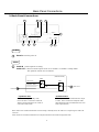
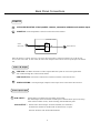
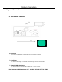
1
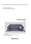
INSTRUCTION MANUAL
Digital Single Channel Recorder
EDSR100H
V1.0
About this manual
Before installing and using this unit, please read this Manual carefully.
Be sure to keep it handy for later reference.
Safety Precautions
Safety Precautions
Refer all work related to the installation of this product to qualified service
personnel or system installers.
Do not block the ventilation opening or slots on the cover.
Do not drop metallic parts through slots.This could permanently damage
the appliance. Turn the power off immediately and contact qualified service
personnel for service.
Do not attempt to disassemble the appliance.To prevent electric shock,
do not remove screws or covers. There are no user-serviceable parts
inside. Contact qualified service personnel for maintenance. Handle the
appliance with care. Do not strike or shake, as this may damage the
appliance.
Do not expose the appliance to water or moisture, nor try to operate it in
wet areas. Do take immediate action if the appliance becomes wet.
Turn the power off and refer servicing to qualified service personnel.
Moisture may damage the appliance and also cause electric shock.
Do not use strong or abrasive detergents when cleaning the appliance
body. Use a dry cloth to clean the appliance when it is dirty. When the
dirt is hard to remove,use a mild detergent and wipe gently.
Do not overload outlets and extension cords as this may result in a risk of
fire or electric shock.
Do not operate the appliance beyond its specified temperature, humidity
or power source ratings. Do not use the appliance in an extreme
environment where high temperature or high humidity exists. Use the
appliance at temperature within 0oC ~ +40oC and a humidity below 90%.
The input power source for this appliance is AC100~240V.
Safety Warning
WARNING
TO REDUCE RISK OF FIRE OR ELECTRIC SHOCK,
DO NOT EXPOSE THIS APPLIANCE TO RAIN OR MOISTURE.
CAUTION
DO NOT REMOVE COVER. NO USER SERVICEABLE PARTS INSIDE.
REFER SERVICING TO QUALIFIED SERVICE PERSONNEL.
Note:
This equipment has been tested and found to comply with the limits for a Class A digital device,
The changes or modifications not expressly approved by the party responsible for compliance
could void the user's authority to operate the equipment.
Note:
This is a class A product. In a domestic environment this product may cause radio interference
In which case the user may be required to take adequate measures.
Notice:
The information in this manual was current when published. The manufacturer
reserves the right to revise and improve its products. All specifications are
therefore subject to change without notice.
Safety Precautions
Safety Precautions
The lightning flash with an arrowhead symbol, within an
equilateral triangle, is intended to alert the user to the presence
of uninsulated ” dangerous voltage” within the product’s enclosure
that may be of sufficient magnitude to constitute a risk of electric
shock to persons
The exclamation point within an equilateral triangle is
intended to alert the user to presence of important operating
and maintenance(servicing)instructions in the literature
accompanying the appliance.
Warning:
Electrostatic-sensitive device. Use proper
CMOS/MOSFET handing precautions to avoid
electrostatic discharge.
UNPACKING
Unpack carefully.
This is electronic equipment and should be
handled carefully.
Check to ensure that the following items are included;
Warning :
To prevent fire or shock hazard, do not expose units not
specifically designed for outdoor use to rain or moisture.
•1.
•2.
•3.
•4.
•5.
•6.
Attention:
Installation should be performed by qualified service personnel only
in accordance with the National Electrical Code or applicable local codes.
If an item appears to have been damaged in shipment,
replace it properly in its carton and notify the shipper.
If any items are missing, notify your
Everfocus Electronics Corp. Sales Representative or
Customer Service. The shipping carton is the safest
container in which the unit may be transported.
Save it for possible future use.
Power Disconnect:
Units with or without ON-OFF switches have power supplied to the unit
whenever the power code is inserted into the power source; however, the
unit is operational only when the ON-OFF switch is in the ON position.
The power cord is the main power disconnect for all units.
External Power Supplies
Use only the recommended power supplies.
Power supplies must comply with the requirement of
the latest version of IEC 60065/CNS 13439. Substitutions
may damage the unit or cause a fire or shock hazard
AC100V~240V Power Cords
AC100V~240V power cords
Digital Single Channel Recorder
User’s manual
Power Cord
CF card reader
Adapter
HDD tray key and screws
Service
If the unit ever needs repair service, the customer
should contact the nearest Everfocus Electronics Corp.
Service Center for return authorization and shipping
instruction.
Important Safeguards
Important Safeguards
Read Instruction---All the safety and operating instructions should be read before the init is operated
Retain Instructions---The safety and operating instructions should be retained for future reference.
Heed Warnings—All warnings on the unit and in the operating instructions should be adhered to.
Follow Instructions—All operating and use instructions should be followed
Cleaning—Unplug the unit from the outlet before cleaning. Do not use liquid cleaners or aerosol cleaners.
Use a damp cloth for cleaning
Attachments—Do not use attachment not recommended by the product manufacturer as they may cause hazards.
Water and Moisture—Do not use this unit near water-for example, near a bath tub, wash bowl, kitchen sink,
or laundry tub, in a wet basement, near a swimming pool, in an unprotected outdoor installation, or any area which is
classified as a wet location.
Servicing—Do not attempt to service this unit yourself as opening or removing covers may expose you to dangerous
voltage or other hazards. Refer all servicing to qualified service personnel.
Power Cord Protection—Power supply cords should be routed so that they are not likely to be walked on or pinched by
items placed upon or against them, playing particular attention to cords and plugs, convenience receptacles, and the point
where they exit from the appliance.
Object and Liquid Entry—Never push objects of any kind into this unit through openings as they may touch dangerous
voltage points or short-out parts that could result in a fire or electric shock, Never spill liquid of any kind on the unit.
Table of Contents
1. Product Overview……….…...……………………………………………………………………………………..………….. 1
1.1 Feature………...…….…….….…………………………………….…………..……………………………………………..1
1.2 Specifications………....………………….………………………………..………….………….…………………………...2
2. Front & Rear Panels………...…….………………………………………..…………………………………………………....3
3. Back Panel Connections…….………...……………………………………..…………………………………………………..5
4. System Connection…....………………………...…………………………..…………….…………………….………………..8
4.1 One Camera Connection………….…..…….………………………………………………………..……………………….8
4.2 Multiplexer Connection...……….….………………………………………………...……………...………………………..9
4.3 Quad Connection ( with VCR )………….……………….…………………….…………………..……………………… 10
4.4 Quad Connection ( without VCR)….….………….……………...……………………………………………………...….11
5. Installation………...………………………………………………...……………….….………………………………………12
6. Menu………...……………….……………………………………..……………………………………………………………13
6.1 Clock/Language Setup…...………….…………….….………………………………………………………….………….14
6.2 Daylight Setting Menu..……..……………...…….……….………………………...……………………….……………...15
6.3 Timer Setting Menu……………….…….……....…………………………………………………...…………………..….16
6.4 Normal Record Setting Menu…………………….……....……………………………………………………………...….18
6.5 Alarm Record Setting Menu……………………….………………..………………………………………………………20
6.6 Buzzer Setting Menu…………………….….…………….…………………………...…………………………………….25
6.7 Archive Setting Menu…....………….…………...……………..……………………………………………………………26
6.8 RS232/RS485 Setting Menu……………….………………………………..……………………………………………….27
6.9 System Setting Menu…………………………………………………………………………………………………………28
7. Recording…...……………...……………………………………………………………..……………………………………. 31
7.1 Instant Recording……………..…………………………………………………….……………………………………... 31
7.2 Alarm Recording…………………………………………….………………………………….………………………….. 32
8. Playback…...…………………………………………………….……………………….…………………………………..… 33
8.1 Normal Playback…………………………………………………………………………………………………………... 33
8.2 Search Playback…………………………………………………………………………………………………………… 35
9. Copy………...……………………….…………………………………………………………….…………………….………38
9.1 Still Image Copy……………………………………………………………………………………………………………38
9.2 Copy to Movie File……...………………………………………………………………………………………………….39
10. Interface Specifications……..….……...……………………………………………………………………………………...41
10.1 Transmission setting……..……………………………..………………………….………………………………………41
10.2 Remote Control Protocol…………………………………..………………………………………………………..……..42
11. Remote Controller………….…….……………………………………………………………………………...……………45
12. Appendix-A/Time Lapse Mode Recording Time…….……..………………………………………………………....….....46
12.1 Recording with 80 GB HDD…..……..………...………………….…………………………………………….………..46
12.2 Recording with 160 GB HDD…………..………..……………………………………………………………………….47
13. Appendix-B/ Security Lock setting..…...…….………………………………………………………………………………48
Product Overview and Features
1. Product Overview
The Digital Video Recorder is the first true VCR replacement designed particularly for the security industry,
seamlessly combining high-resolution video multiplexing and digital recording.
The Digital Video Recorder at speeds up to 60/50 fields per second with NTSC/PAL formats and replay event
instantly.
The Digital Video Recorder incorporates all the benefits of digital video recording, is simple to install, and operates
just like a VCR. The highly efficient compression technology, as well as the superior clarity and detail of recorder images,
make the Digital Video Recorder stand out from its competitors as the best choice for security surveillance.
1.1 Features
Digital Recording provides superior quality images
Hard-disk hot-swapping capability
Pre-Alarm image recording
Compatible with most multiplexers
Time lapse and real time recording
Refresh rate up to 60 fps (50 fps for PAL)
Quick Search by date/time, alarm events, and recording list
Fast and slow playback of recorded video in various speeds
On-screen setup menu and system timer
Multi-level password protection
RS-232/RS-485 communication port
Highly stable non-PC based proprietary system
Built-in M-JPEG compression/decompression with configurable quality
Audio recording capability
Programmed with various time-lapse speeds, Data can be stored in Compact Flash Card.
Operation status record log
1
Specifications
1.2 Specifications
Video Input
1 video input with loop through (BNC),
1Vpp/75ohm
Video Output
1 video output (BNC), 1Vpp/75ohm
Video Compression
M-JPEG
Video Resolution
720x484 (NTSC); 720x576 (PAL)
CompactFlash Memory
Yes, Built-in Compact Flash card slot
Alarm Input
Yes
Alarm Output
Yes
Audio
2 inputs; 2 outputs
Video Loss Detection
Yes
RS-232
9-pin female connector
Event Log
Yes
Hard Disk Storage
3.5” IDE type, Hot- swappable
Recording Mode
Continuous, Time-lapse recording,
Timer or Event Recording
Recording Rate
60/50 fps for NTSC/PAL
Playback Rate
60/50 fps for NTSC/PAL
Playback Search
By Date/Time or Event or Segment
Setup
On screen display setup
User Interface
Menu Driven
User Input Device
Front Panel Keypad
RS485
RJ11 Connector
Watch Dog Timer
Yes
Power Consumption
39W
Power Source
AC100~240V
Dimension
320.8mm (L) x 215mm (W) x 100mm (H)
Operating Temperature
0?7~+40?7
Timer
Built-in real time clock
2
Front Panel Keypads
2. Front Panel Keypads
17
18
1
2
3
4
5
6
7
8
19
EDSR100H
22
20
9
10
11
12
13
14
15
16
21
KEY
1
~
4
Left/Right Button: Press
Up/Down Button: Press
or
or
to move the cursor to the left or right
to change the value.
5
ENTER: Press this key to confirm the selection or data changed.
6
BUZZER: Press this key to turn On/OFF the buzzer for all events.
7
8
LOCK : Press and hold the LOCK button over 3 seconds to lock/unlock the function keys of the front panel.
This function is used to avoid unexpected contact with the panel.
MENU: Press this key to enter Setup menu.
9
REC : Press this key to start recording.
10
REV. PLAY : Reverse Play Back.
11
STOP : Press this key to stop recording and play back.
12
PLAY: Play Back.
13
PAUSE: Press this key to pause the playback picture.
14
SEARCH: Press this key to enter the Search Playback Menu.
15
COPY: Press this key to start copy still picture or video stream into Compact Flash card.
3
16
Display: Press this key to switch ON/OFF.
Record
002HR
Record
002HR
Disk:120 GB(0)
Disk:120 GB(0)
Disk size:120GB
2003/04/24 10:41:00
2003/04/24 10:41:00
Display OFF
17
18
19
Display Date/Time
And Operation status
Display Date/Time,
Operation Status,
Disk Status.
HDD KEY: Protect HDD without steal
Hard Disk Tray: Hard Disk holder for HDD.
Jog and Shuttle Dial
Shuttle : In Playback mode,turn the shuttle dial can fast forward/rewind the picture.
In Pause mode, turn the shuttle dial can slow forward/rewind the picture.
Jog Dial :In Pause mode, turn the Jog dial can stop forward/backward the picture.
In Menu mode, turn the Jog dial can change menu page forward/rewind.
20
Compact Flash Card Slot: Insert a Compact Flash Card.
21
LEDs: LEDs for system active, power and ALARM access.
22
Remote Control: IR Remote receiver
4
Back Panel Connections
3. Back Panel Connections
6
10
3
8
MUX MAIN
MONITOR IN
5
4
7
2
9
1
POWER
1
Power in: The main power in.
AUDIO
2
Audio IN : Audio input for recording.
Audio OUT : These two audio outputs can be set to “Enable” or “Disable” in Setup Menu.
The operation of audio out is as follows:
( Internal circuit )
SW2
OFF / Mute
SW1
Playback Audio
A
Audio OUT
Audio IN
Operation of SW2 :
Operation of SW1 :
When in recording or standby mode,
the out of SW1 is connected to Audio IN.
When in playback mode the out of SW1 is
connected to SW2 Audio.
When Playback Audio is enabled then the output
of SW2 will be connected to Playback Audio.
When Playback Audio is disabled then there is no
audio output (MUTE).
When Audio Out is enabled and machine is in Recording or Standby mode, the Audio IN is loop-through to Audio Out
connector.
When Audio Out is enabled and machine is in Playback mode then the Audio Out playback audio.
5
Back Panel Connections
MONITOR
3
MUX MAIN MONITOR: Video input BNC connector, connected to multiplexer main monitor output.
4
MONITOR : Video output BNC connector connected to main monitor.
( Internal circuit )
SW3
MAIN
MONITOR
A
INTERNAL
VIDEO
MONITOR OUT
When the machine is in Menu, Search or Copy mode, the internal Video is switched to Monitor Out, so that the user
can view full screen OSD. In other modes, the Video from multiplexer main monitor will be loop-through to the Monitor
Out.
VIDEO IN /Output
5
VIDEO IN : The BNC connectors of video input enables the system to receive the signals from
each camera through the 75 ohm coaxial cables.
VIDEO OUT(1~2) : Connect the other devices with four cameras to the other devices.
6
VIDEO LOPPING : The loop-through composite video input can be connected to other devices.
Alarm Input/ Output
7
ALM-INPUT :
ALM-OUTPUT :
Normal Open or Normal Close type alarm sensor input.
The Alarm Input can be selected as Normal Open or Normal Close input in the setup
menu. When an alarm occurs, alarm recording will automatically start.
Normal Close Alarm output. In normal condition, this terminal is
shorted to the terminal of ALM-COM. In alarm status, it is open
between ALM-NC and ALM-COM terminals.
6
Back Panel Connections
RS232
RS232 connector : Connect D-Sub 9 pins connector to RS232 ports for remote control
8
RS485
9
RS485 connector : Cascade multi Digital Video Recorder.
10
FAN: Cooling FAN.
7
System Connection
4. System Connection
4.1 One Camera Connection.
(1)
(2)
MUX MAIN
MONITOR IN
(3)
Main Monitor
(1 ) :Video out:
The Camera Video Output is connected to the Video In at the rear panel.
(2 ) : Audio Out:
The camera audio output is connected to the audio input terminal at the rear panel.
(3) : System Main Monitor Output:
The main monitor is connected to the VIDEO OUT 1 BNC connector.
Note: Please set the Multiplexer item to OFF . (NORMAL RECORD SETTING MENU)
8
System Connection
4.2 Multiplexer Connection.
Multiplexer
MAIN MONITOR OUTPUT
VCR IN
(2)
(3)
VCR OUT
(1)
MUX MAIN
MONITOR IN
(4)
(1): Multiplexer VCR Out :
This connects to the VIDEO IN connector at the rear panel.
Main Monitor
(2) :Multiplexer VCR In :
This connects to the VIDEO OUT 1 connector at the rear panel.
(3) :Multiplexer Main Monitor Output:
This connects to the MUX. MAIN MONITORIN IN connector at the rear panel.
(4) :System Main Monitor Out:
Connect the MAIN MONITOR OUTPUT connector to the main monitor.
Note: Please set the Multiplexer item to ON . (NORMAL RECORD SETTING MENU)
9
System Connection
4.3 Quad Connection. ( Quad with VCR in VCR out connector)
Quad
MAIN MONITOR OUTPUT
(3)
VCR IN
(2)
VCR OUT
(1)
MUX MAIN
MONITOR IN
(4)
Main Monitor
(1): Quad VCR Out:
This connects to the VIDEO INPUT connector at the rear panel.
(2) : Quad VCR In:
This connects to the VIDEO OUTPUT connector at the rear panel.
(3) : Quad Main Monitor Out:
This connects to the MUX. Main connector at the rear panel.
(4) : System Main Monitor Output:
Connect the MAIN MONITOR OUTPUT connector to the main monitor.
Note: Please set the Multiplexer item to ON . (NORMAL RECORD SETTING MENU)
10
System Connection
4.4 Quad connection. ( Quad without VCR in VCR out connector)
Quad
VIDEO OUT
(1)
MUX MAIN
MONITOR IN
(2)
Main Monitor
(1): Quad Video Out ( to Video Recorder):
This connects to the VIDEO INPUT connector at the rear panel.
(2): System Main Monitor Output:
Connect the MAIN MONITOR connector to the main monitor.
Note: Please set the Multiplexer item to OFF . (NORMAL RECORD SETTING MENU)
11
INSTALLATION
5. Installation
(1) Insert a HDD (IDE) for Video Storage
The HDD should be set as MASTER.
( Normally the default setting of HDD is Master)
Notice: After the hard disk case is inserted into the hard disk tray, be sure to
Turn the tray key in lock position. Otherwise, hard disk will not be detected and
The System Loading procedure can not be completed.
(2) Connect cable for video/audio input and video/audio out,
The POWER LED lights if power is normal.
(3) Switch Power On
The detail connection is described in SYSTEM CONNECTION.
(4)
MENU
Press MENU key to enter SET UP MENU.
Once inside the main menu you will find there are
nine set up pages as below:
(5)
1.
CLOCK/LANGUAGE SETTING MENU
2.
DAYLIGHT SAVE SETTING MENU
3.
TIMER SETTING MENU
4.
NORMAL RECORD SETTING MENU
5.
ALARM RECORD SETTING MENU
6.
BUZZER SETTING MENU
7.
ARCHIVE SETTING MENU
8.
RS232/RS485 SETTING MENU
9.
SYSTEM SETTING MENU
Turn the jog dial clockwise or counterclockwise to change set up page.
12
MENU
6. MENU FLOW
Turn the Jog dial clockwise or counterclockwise to change
setting menu page.
ALARM RECORD
SETTING MENU
( See page 20 )
CLOCK/LANGUAGE
SETTING MENU
( See page 14 )
ALARM RECORD SETTING MENU
CLOCK/LANGUAGE SETTING MENU
DATE
TIME
ALARM OPERATION
RECORDING SPEED
RECORDING QUALITY
ALARM – IN TYPE
ALARM -RESET TYPE
ALARM DURATION TIME
: 2003/04/24 TUE
: 13:01:02
MENU LANGUAGE
PRE-ALARM OPERATION
RECORDING SPEED
: ENGLISH
ON
002 HR
STANDARD
N.O.
N.O.
05 SECS
:
:
:
:
:
:
: ON
: 002 HR
BUZZER
SETTING MENU
( See page 22 )
DAYLIGHT SETTING MENU
( See page 15 )
BUZZER SET SETTING MENU
BUZZER
ALARM –IN
RECORD -IN
DISK FULL
VIDEO LOSS
TIMER
DAYLIGHT SETTING MENU
DAYLIGHT SAVING :OFF
START ON JAN 1ST MON
FROM 00:00 TO 00:00
END ON JAN 1ST MON
FROM 00:00 TO 00:00
:
:
:
:
:
:
ENABLE
ON
ON
ON
ON
ON
ARCHIVE SETTING MENU
( See page 23 )
ARCHIVE SETTING MENU
: 720 X 480
: ON
: BOTTOM
: ON
: BOTTOM
PICTURE SIZE
TIME STAMP
TIME STAMP POS
WATER MARK
WATER MARK POS
TIMER SETTING MENU
( See page 16 )
RS232/RS485 SETTING MENU
( See page 23 )
TIMER SETTING MENU
WEEK
SUN
SUN
SUN
SUN
SUN
SUN
SUN
SUN
SUN
SUN
SUN
SUN
START
00:00
00:00
00:00
00:00
00:00
00:00
00:00
00:00
00:00
00:00
00:00
00:00
STOP
00:00
00:00
00:00
00:00
00:00
00:00
00:00
00:00
00:00
00:00
00:00
00:00
SPEED
002 HR
002 HR
002 HR
002 HR
002 HR
002 HR
002 HR
002 HR
002 HR
002 HR
002 HR
002 HR
QUALITY
STABDARD
STABDARD
STABDARD
STABDARD
STABDARD
STABDARD
STABDARD
STABDARD
STABDARD
STABDARD
STABDARD
STABDARD
SET
OFF
OFF
OFF
OFF
OFF
OFF
OFF
OFF
OFF
OFF
OFF
OFF
RS232/RS485 SETTING MENU
RS232/RS485
RS232/RS485 ID
BUAD RATE
PARITY
DATA BIT
STOP BIT
SYSTEM SETTING MENU
( See page 25 )
NORMAL RECORD
SETTING MENU
( See page 18 )
SYSTEM SETTING MENU(V1.0 05/19)
PLAY WITH AUDIO 1
PLAY WITH AUDIO 2
PASSWORD ENABLE
PASSWORD
FIELD CODE LINE
DISK RENEW
SYSTEM UPDATE
LOAD DEFAULT
CF RENEW
NORMAL RECORD SETTING MENU
SPEED
QUALITY
MULTIPLEXER
DISK FULL
:RS232
:01
:9600
:NONE
:8
:2
: 002
: STANDARD
: OFF
: REWRITE
13
:
:
:
:
:
:
:
:
:
NO
NO
OFF
888888
12
NO
NO
NO
NO
MENU
6.1 CLOCK/ LANGUAGE SETTING MENU
CLOCK/LANGUAGE SETTING MENU
DATE : 2003/04/24 TUE
TIME : 13:01:02
: ENGLISH
MENU LANGUAGE
VERSION: 1.0 (2003/05/26)
In CLOCK/LANGUAGE SETTING MENU , we SET
(1) DATE : Current date
Year: 2000 ~ 2099
Month: 01~ 12
(2) TIME : Current time
Hour: 00 ~ 23
Minute : 00 ~ 59
Date: 01~31
Second: 00 ~ 59
(3) MENU LANGUAGE:
ENGLISH
Left/Right Button: Press
Up/Down Button: Press
or
or
14
to move the cursor to the left or right
to change the value.
MENU
6.2 DAYLIGHT SETTING MENU
DAYLIGHT SETTING MENU
DAYLIGHT SAVING: OFF
START ON JAN 1ST MON
FROM 00:00 TO
00:00
END ON JAN 1ST MON
FROM 00:00 TO 00:00
In DAYLIGHT SETTING MENU , we define:
(1)
DAYLIGHT SAVING:
Select “ON” or “OFF” while the daylight saving time function is enabled or not.
(2)
START ON:
“JAN ”Use the arrow to set the present month
Sunday
January
February
July
August
March
May
April
September
October
June
November
December
“1ST ” Use the arrows to set the present week
1ST
2ST
3ST
LAST
4ST
“SUN”Use the arrow to set the present date
Sunday
Monday
Tuesday
Wednesday
Thursday
Friday
Saturday
“FROM” 00:00 “TO”00:00: Use the arrow to set the start time value.
Left/Right Button: Press
Up/Down Button: Press
or
or
15
to move the cursor to the left or right
to change the value.
MENU
6.3 TIMER SETTING MENU
TIMER SETTING MENU
WEEK
SUN
SUN
SUN
SUN
SUN
SUN
SUN
SUN
SUN
SUN
SUN
SUN
START
00:00
00:00
00:00
00:00
00:00
00:00
00:00
00:00
00:00
00:00
00:00
00:00
STOP
23:59
23:59
23:59
23:59
23:59
23:59
23:59
23:59
23:59
23:59
23:59
23:59
SPEED QUALITY
002 HR
002 HR
002 HR
002 HR
002 HR
002 HR
002 HR
002 HR
002 HR
002 HR
002 HR
002 HR
STANDARD
STANDARD
STANDARD
STANDARD
STANDARD
STANDARD
STANDARD
STANDARD
STANDARD
STANDARD
STANDARD
STANDARD
SET
OFF
OFF
OFF
OFF
OFF
OFF
OFF
OFF
OFF
OFF
OFF
OFF
In TIMER SETTING MENU, we define
The monitored image can be recorded automatically by setting the start and end
times in TIMER SET SETTING MENU, we can set the schedule to record for a whole week.
(1) WEEK:
This selects the day for the timer .Records each day’s schedule.
(2) START:
This key is used to start the timer recording.
(3) STOP:
This key is used to end the time for recording.
.
16
(4) Speed :
When SPEED FORMAT is set to HOUR, the recording speed
can be set from 2/3 (NTSC/PAL)HR to 960HR.
When SPEED FORMAT is set to IPS, the recording speed can
be set from 1~60/1~50(NTSC/PAL)IPS.
(5) QUALITY:
Picture Quality
There are six quality levels for recording
LOWER
LOW
BASIC
STANDARD
HIGH
SUPERIOR
:
:
:
:
:
:
15 KB
20 KB
25 KB
30 KB
35 KB
40 KB
(6) SET:
Set “ON” when using timer recording.
Set “OFF” when not using timer recording
17
MENU
6.4 NORMAL RECORD SETTING MENU
NORMAL RECORD SETTING MENU
SPEED
QUALITY
MULTIPLEXER
DISK FULL
:
:
:
:
002 HR
STANDARD
OFF
REWRITE
In NORMAL RECORDING MENU, we define
(1) SPEED :
Recording Speed
The user can select the recording speed from 2/3 (NSC/PAL) HR to 960 HR.
(2) QUALITY:
Picture Quality
There are six quality levels for recording
:
LOWER
:
LOW
:
BASIC
STANDARD :
:
HIGH
SUPERIOR :
15 KB
20 KB
25 KB
30 KB
35 KB
40 KB
18
MENU
(3) MULTIPLEXER:
ON/OFF : The user can select Multiplexer connection or One Camera connection
ON : The video input from MUX MAIN MONITOR connector at the rear
panel will be looped through to the main monitor out when the
recorder is not in MENU mode.
OFF : The main monitor output is similar to the video out connector.
(4) Disk Full:
STOP : When the disk is full, the machine will STOP recording.
REWRITE : When the disk is full, the current video will OVERWRITE the existing video
from the beginning of HDD.
Left/Right Button: Press
Up/Down Button: Press
19
or
or
to move the cursor to the left or right
to change the value.
MENU
6.5 ALARM RECORD SETTING MENU
ALARM RECORD SETTING MENU
ALARM OPERATION
RECORDING SPEED
RECORDING QUALITY
ALARM – IN TYPE
ALARM -RESET TYPE
ALARM DURATION TIME
:
:
:
:
:
:
PRE-ALARM OPERATION
RECORDING SPEED
: ON
: 003 HR
ON
003 HR
STANDARD
N.O.
N.O.
05 SECS
In ALARM RECORDING MENU, we define
(1) ALARM OPERATION :
ON : Records when alarm occurs.
OFF : Does not record when alarm occurs.
(2) RECORDING SPEED : The recording speed in alarm duration.
The max. recording speed is 2/3 (NTSC/PAL) HR.
The min. recording speed is 960 HR.
(3) RECORDING QUALITY :
Select the Recording picture quality when alarm occurs.
LOWER
LOW
BASIC
STANDARD
HIGH
SUPERIOR
:
:
:
:
:
:
15 KB
20 KB
25 KB
30 KB
35 KB
40 KB
20
MENU
(4) ALARM –IN TYPE :
N.O. : Normal Open,
N.C. : Normal Close
(5) ALARM - RESET TYPE:
N.O. : Normal Open,
N.C. : Normal Close
(6) ALARM DURATION TIME :
Alarm recording starts from the beginning of alarm and stops at the end of the duration.
The max. duration is NON - STOP, the min. duration is 5 Seconds.
(7) PRE-ALARM OPERATION :
ON : Record the picture in pre-alarm recording speed in pre-alarm period.
OFF : No pre-alarm recording before alarm occurs.
(8) RECORDING SPEED :
This is the recording speed in the pre-alarm period.
The max. recording speed is 2/3 (NTSC/PAL) HR.
The min. recording speed is 960 HR.
(9) PRE – ALARM TIME :
The duration of pre-alarm recording period
In 2/3 hour Real Time recording mode, the duration of pre-alarm is about five seconds.
Left/Right Button: Press
Up/Down Button: Press
or
or
to move the cursor to the left or right
to change the value.
Notice :
If the alarm occurs when it is in standby mode or in normal recording mode,the recording quality will be the
same as the normal recording quality.
If the alarm occurs when it is in timer recording mode , the recording quality will be the same as the value
set in timer recording quality.
21
MENU
Note: Alarm Connectors (DB-15)
The alarm connector, figure 1, is used to provide one
sensor alarm input for each camera input.
For easy operation, an alarm extension board,
figure 2, is provided to connect to the alarm
connector.
1
8
15
Each alarm input requires two wires, one wire
connects to the desired alarm input pin, the
second wire connects to the multiplexer
ground. The alarm signal assignment is shown
at the following table, table 1.
9
<Figure 1>
10 11 12
9
13 14 15
PSR1D0080A
8
7
6
5
<Figure 2>
<Table 1>
PIN #
1
2
3
4
5
6
7
8
NAME
GND
ALARM
RECIN
NC1
NC2
ALMRST
GPIN
GND
PIN #
9
10
11
12
13
14
15
22
NAME
GPOUT
DISK_FULL
VD_LOSS
VCR_SW
ALM_NC
ALM_NO
ALM_COM
4
3
2
1
MENU
(a.) Alarm out
There are two ways to do the alarm out connection:
Normally open connection (use pin # 13 and # 14)
2 1
15
9
RELAY
COIL
To external
equipment
8
Normally Closed Connection (use pin # 13 and # 12)
2 1
15
9
RELAY
COIL
8
To external
equipment
23
MENU
(c) Alarm in and alarm reset
There is 1 alarm sensor in for 1 channel and 1 alarm reset in, the
alarm input can be set to Normally Open or Normally Closed by user.
ALARM
CIRCUIT
SENSOR 1
8
15
2 1
9
ALARM RESET
Alarm in
There is one alarm input. Please connect the alarm input in the same sequence as the
camera input BNC.
When alarm signal comes in, the Digital Video Recorder will do the following:
1. Display Alarm Message
2. Turn on the buzzer if the buzzer setting is on.
The ALARM in can be selected as normally open input or normally closed input:
Normally Open : If the alarm input is selected as Normally Open input, then the
(N.O.)
input is opened normally, and shorted to the ground means an alarm happens.
Normally Close : If the alarm input is selected as Normally Close input, then the
(N.C.)
input is shored to the ground normally, and opened input means an alarm
happens.
24
MENU
6.6 BUZZER SETTING MENU
BUZZER SETTING MENU
BUZZER
ALARM –IN
RECORD -IN
DISK FULL
VIDEO LOSS
TIMER
: ENABLE
:
:
:
:
:
ON
ON
ON
ON
ON
In BUZZER SETTING MENU, we SET the buzzer ON/OFF under the following conditions:
(1) BUZZER :
ENABLE: Turns the buzzer on.
DISABLE: Turns the buzzer off.
User can press Enter button to enable/disable in Record/Playback mode.
(2) ALARM –IN :
ON, the buzzer will sound when the alarm occurs.
(3) RECORD – IN:
ON, the buzzer will sound when Record-IN signal is applied on the Record-IN terminal.
(4) DISK FULL :
ON, the buzzer will sound when disk is near full 99.7%
(5) VIDEO LOSS :
ON, the buzzer will sound when the video loses.
(6) TIMER :
ON, the buzzer will sound when timer record occurs.
Left/Right Button: Press
Up/Down Button: Press
25
or
or
to move the cursor to the left or right
to change the value.
MENU
6.7 ARCHIVE SETTING MENU
ARCHIVE SETTING MENU
PICTURE SIZE
TIME STAMP
TIME STAMP POS
WATER MARK
WATER MARK POS
MULTIPLEXER
:
:
:
:
:
:
720x576
ON
BOTTOM
ON
BOTTOM
NONE
(1) PICTURE SIZE :
Selects picture size for copying image to CF card
Big size:720x576
Small size:352x288
(2) TIME STAMP :
ON: The time stamp will show on the picture when copying image to CF card.
OFF: The time stamp will not show on the picture when copying image to CF card.
(3) TIME STAMP POS:
BOTTOM: The time stamp will show on the bottom
TOP: The time stamp will show on the top
(4) WATER MARK:
ON: Shows a water mark on the picture when copying image to CF card.
OFF: This erases the water mark on the picture when copy image to CF card.
(5) WATER MARK POS:
BOTTOM: Water mark will show on the bottom
TOP: Water mark will show on the top
(6) MULTIPLEXER:
Multi-brand of multiplexer for user choose: NONE/EVERFOCUS 4BDX/EVERFOCUS 4CDX/EVERFOCUS
16CTX/ROBOT MU99P/APPRO MPX-9016/DM NPRITE4 /ATV QSP-860MPX
Left/Right Button: Press
Up/Down Button: Press
26
or
or
to move the cursor to the left or right
to change the value.
MENU
6.8 RS232/RS485 SETTING MENU
RS232/RS485 SETTING MENU
RS232/RS485
RS232/RS485 ID
BAUD RATE
PARITY
DATA BIT
STOP BIT
: RS232
: 01
: 9600
: NONE
:8
:2
In the RS232/RS485 SETTING MENU, we define
(1) RS232/RS485: Choose RS232 or RS485 for activated.
(2) RS232/RS485 ID: This entry is used to assign each device with its own ID code, when more than on unit is
used in one system through RS232/RS485.
There are two ID code for the Digital video recorder : 001 or 002
(3) BAUD RATE: There are 6 different speeds that can be used to transmit instruction or
information through the RS232/RS485 port on the device, 1200 baud,2400 baud,4800 baud,9600 baud,
19200 baud,and 3840 baud. The default setting from the factory is 9600 baud.
(4) PARITY: Select parity lever: NONE/ODE/EVEN
(5) DATA BIT: Select data bit : 8 or 7
(6) STOP BIT: Select stop bit: 1 or 2
Left/Right Button: Press
Up/Down Button: Press
or
or
27
to move the cursor to the left or right
to change the value.
MENU
6.9 SYSTEM SETTING MENU
SYSTEM SETTING MENU
PLAY WITH AUDIO 1
PLAY WITH AUDIO 2
PASSWORD ENABLE
PASSWORD
FIELD CODE LINE
DISK RENEW
SYSTEM UPDATE
LOAD DEFAULT
CF RENEW(FAT16)
:
:
:
:
:
:
:
:
:
NO
NO
OFF
888888
12
NO
NO
NO
NO
(1) PLAY WITH AUDIO 1
PLAY WITH AUDIO 2 :
ON/OFF : Play back with or without audio.
(2) PASSWORD ENABLE :
YES/NO : User can set the PASSWORD ON or OFF to enter the system setting menu.
YES: Selects the PASSWORD to enter the system setting menu .
NO: Turns off the PASSWORD to enter the system setting menu.
(3) PASSWORD :
When selecting YES for PASSWORD ENABLE, to unlock key a password
is required. The code is six digits long and can be a digit from 1 to 8.
Once you have activated the password, whenever you press the LOCK button for unlock
the system will ask you to enter the password.
PASSWORD:
******
Therefore, be sure to make a note of the password.
28
MENU
(4) FIELD CODE LINE : When the system is connected to the Multiplexer, it is used to adjust the field code
of the Multiplexer.
The values: 00~20
The default value is 13, it is suitable for most of the multiplexers.
If the field code line appears on the top of each playback channel, decrease the value.
If multiplexers can not playback properly ,increase the value.
(5) DISK RENEW :
YES/NO : Activates the Renew HDD option.
DISK RENEW
NO
YES
DISK RENEW
NO
Press NO to renew HDD and Press ENTER key to Exit.
Press Yes to Renew HDD and Press ENTER key to Exit.
YES
(6) SYSTEM UPDATE :
YES/NO : Updates the system.
YES : Copy the update files into Compact Flash card ON PC and insert the
Compact Flash card into the slot, and then press ENTER key to update system.
The “ Reading Program………” will be shown on the screen during the process.
The “ Success” will be shown on the screen after system update.
Notice: After the system is updated successfully, be sure reboot the system.
29
MENU
(7) LOAD DEFAULT :
LOAD DEFAULT
NO
YES
LOAD DEFAULT
NO
YES
Press NO to load default and Exit.
Press YES to load default value.
(8) CF RENEW:
Two of modes for choice, YES or NO.
CF RENEW
NO
YES
CF RENEW
NO
NO: will not format CF card
YES: will format CF card
YES
Left/Right: Press
Up/Down: Press
or
or
to move the cursor to the left or right
to change the value.
30
Recording
7.1 INSTANT RECORDING
Press Record key to start the recording immediately.
Video out
When pressed, the pictures being monitored
will be recorded in the HDD.
REC
•The recording rate and recording quality are
set in the Record Set menu
RECORD
002 HR
• “ REC ” button light up in the operating
display
Press Stop key to stop recording.
• Stop key can be activated only in recording mode.
STOP
•When the HDD is full, the machine will Stop recording automatically
or Overwrite from the beginning of the HDD. It depends on the
setting in HDD setting
31
Recording
7.2 ALARM RECORDING
The monitor image will automatically record when alarm occurs and stops recording at the end of the alarm
duration period.
Instant recording and timer recording will stop when an alarm occurs.
MENU
Press MENU key and turn the jog dial to select the ALARM
RECORDING SETTING MENU.
RECORDING OPERATION:
ON: Enables alarm recording,
OFF :Disables alarm recording.
RECORDING SPEED:
Set the recording speed when alarm occurs.
RECORDING QUALITY:
In alarm duration, the recording quality can be set which is different from instant or timer recording.
ALARM – IN TYPE:
Select the type of alarm-in input to be Normal Close (N.C.) or Normal Open (N.O.)
ALARM – RESET TYPE:
Select the type of alarm-reset input to be Normal Close (N.C.) or Normal Open (N.O.)
ALARM DURATION TIME:
Alarm duration from 5 seconds to NON – STOP.
PRE-ALARM OPERATION:
ON: Enables pre-alarm recording,
OFF: Disables pre-alarm recording.
RECORDING SPEED:
Set the recoding speed in pre-alarm duration.
Notice:
The recording quality in pre-alarm duration is the same as recording quality before alarm occurs. If the recorder
is not recording before alarm occurs, the recording quality in pre-alarm duration will be the same as instant
recording quality.
32
Playing Back
8.1 NORMAL PLAYBACK
(1) Playback
Press the PLAY key to start playing back the stored image/audio from
the last SEGMENT.
PLAY
Press the REV.PLAY key to start reverse playing back the stored
image/audio from the last segment.
REV.PLAY
(2) STOP
Press the STOP key to stop playing back.
STOP
(3) Fast Forward/Reverse Playback
Press the PLAY key to start playing back.
PLAY
Turn the shuttle dial clockwise and fast forward playback starts.
The speed will be shown on the LCD at the right upper corner of the screen.
>> 2, 4, 6, 8, 16, 32, 600X
Turn the shuttle dial counterclockwise and fast reverse playback starts.
The speed will be shown on the LCD.
<< 2, 4, 6, 8, 16, 32, 600X
33
Playing Back
(4) Slow Forward/Reverse Playback
Press PAUSE key to freeze the playing back picture.
PAUSE
Turn the shuttle clockwise and slow forward playback starts.
The speed will show on the LCD at the corner of the screen.
>> 1/2, 1/4, 1/6, 1/8, 1/10, 1/16, 1/32
Turn the shuttle counterclockwise and slow reverse playback starts.
The speed will show on the LCD at the corner of the screen.
<< 1/2, 1/4, 1/6, 1/8, 1/10, 1/16, 1/32
(5) Frame/Field advance Forward/Reverse
Press PAUSE key to freeze the picture.
PAUSE
Turn the jog dial clockwise to advance the still image Frame/Field by
Frame/Field .
Turn the jog dial counterclockwise to rewind the still image Frame/Field by
Frame/Field .
The Frame/Field feed speed will increase if the jog dial is turned quickly.
34
Playing Back
8.2 SEARCH PLAYBACK
(1) Segment Search Playback
Press the SEARCH key to enter the Search menu.
SEARCH
SEARCH MENU
BY SEGMENT LIST
BY ALARM LIST
BY DATA TIME
Press the
select file search.
keys to move the cursor to BY SEGMENT LIST and press ENTER key to
SEGMENT SEARCH
1
2
3
Alarm
Timer
Timer
2002/04/24 19/03/29
2002/04/25 12/30/30
2002/05/20 12/00/00
Alarm:ALARM RECORD
Timer: TIMER RECORD
Press the
keys to move the cursor to the segment you want to playback. Press
Enter to select the segment.
When the selection list is full, turn the jog dial clockwise to select next page list for search
other list.
After the starting time is confirmed, press Enter to start playing back.
35
Playing Back
(2) Alarm Search Playback
Press SEARCH key to enter the Search menu.
SEARCH
SEARCH MENU
BY SEGMENT LIST
BY ALARM LIST
BY DATE TIME
Press the
keys to move the cursor to BY ALARM LIST and press ENTER
key to select alarm search.
ALARM SEARCH
1 Alarm 2002/04/24 19/03/29
2 Timer 2002/04/25 12/30/30
3 Timer 2002/05/20 12/00/00
Alarm : PRE-ALARM RECORD
Timer : TIMER RECORD
Press the
keys to move the cursor to select the alarm image to be played back.
When the selection list is full, turn the jog dial clockwise to select next page for search
other list.
The alarm image will be played back from the pre-alarm period and stop at the end of alarm
duration.
36
Playing Back
(3) Date/Time Search Playback
Press SEARCH key to enter the Search menu.
SEARCH
SEARCH MENU
BY SEGMENT LIST
BY ALARM LIST
BY DATE/TIME
Press the
select file search.
keys to move the cursor to BY DATE/TIME and press ENTER key to
DATE/TIME SEARCH
YEAR/MM/DD HH:MM:SS
2002 04 24 19 03 35
Press the
keys to move the cursor.
Press the
keys to increase/decrease the data.
Press Enter and the playback starts from the date/time set in the menu.
Notice: If there is no image stored in the date/time specified then the machine will
start playing back from the nearest set time automatically.
37
COPY
9. COPY
Insert a Compact Flash card into the Compact Flash slot on the front panel.
When inserting the Compact Flash card, make sure that the direction of insertion is
correct.
9.1 STILL IMAGE COPY
Press the PLAY key to start playing back.
PLAY
Press the PAUSE key to freeze the picture.
PAUSE
Turn the jog dial clockwise or counterclockwise to move to your desired
image of choice .
COPY
While the image to be displayed as your desired image of choice ,
press the COPY key. The “ Copying …” will be shown on the screen during
the process. The “ Success” will be shown on the screen after file copied
Notice: Copied images are stored as a single picture.
Copied files are saved as .JPG file.
38
COPY
9.2 COPY TO MOVIE FILE
Press the PLAY key to start playing back.
PLAY
Press COPY key and then the copy menu appears.
COPY
COPY TO MOVIE FILE
Press COPY
Press PLAY
Press PAUSE
Press SEARCH
Press STOP
PLAY
To Step Copy
To Continue Copy
To Stop Continue
To End Copy
To End Play
Press PLAY key to continue Copy Movie File.
39
COPY
PAUSE
SEARCH
STOP
Press the PAUSE key to stop continue copy.
Press SEARCH key to end copy.
Press STOP key to end play.
Notice: Copied images are stored as a movie picture.
Copied files are saved as .MOV file.
Use QuickTime to play the retrieved .MOV files.
You may download QuickTime at www.apple.com.
The playback version for QuickTime is free.
40
Interface Specifications
RS232
This Digital Single Channel Recorder may be controlled by a computer or a terminal via
the standard D-SUB 9-pin RS-232 connector.
D-SUB 9-pin connector specifications
1 2 3 4 5
6 7 8 9
The pin assignment of the 9-pin D-SUB connector
Digital Video Recorder
PIN #
1
2
3
4
5
6
7
8
9
HOST
NAME
NOT CONNECTED
TXD
RXD
NOT CONNECTED
GROUND
NOT CONNECTED
NOT CONNECTED
NOT CONNECTED
NOT CONNECTED
PIN #
1
2
3
4
5
6
7
8
9
NAME
NOT CONNECTED
RXD
TXD
NOT CONNECTED
GROUND
NOT CONNECTED
NOT CONNECTED
NOT CONNECTED
NOT CONNECTED
10.1 Transmission setting
There are 6 different speeds that can be used to transmit instruction or
information through the RS232/RS485 port on the device, 1200 baud,2400 baud,4800 baud,9600 baud,
19200 baud,and 3840 baud.
The default setting from the factory is 9600 baud.
Please refer to Chart 6.11 (page27) for details.
41
Interface Specifications
10.2 Remote Control Protocol
A computer or a terminal can be used to control the unit by sending the packet as following.
=========================================================
Digital Video Recorder 485/232 Control Code Protocol
=========================================================
1-1. Sample control code packets
Example1 : A packet that send "REC" key to Digital Video Recorder(ID=5)
0x85
0x00
0x05
0x4B
0x08
0x5D
(length)
(Receiver ID high byte)
(Receiver ID low byte)
(OPcode = key )
(DATA1 = "Rec" keycode )
(checksum)
Example2 : A packet that send "PAUSE" key to Digital Video Recorder(ID=4999)
0x85
0x27
0x07
0x4B
0x0C
0x0A
(length)
(Receiver ID high byte)
(Receiver ID low byte)
(OPcode = key )
(DATA1 = "Pause" keycode )
(checksum)
Example3 : A packet that send "PLAY" key to all Digital Video Recorder (broadcast)
0x85
0x7f
0x7f
0x4B
0x0B
0x59
(length)
(Receiver ID high byte)
(Receiver ID low byte)
(OPcode = key )
(DATA1 = "Play" keycode )
(checksum)
42
2-1. The format of message packet is as follows:
Length Byte (Prefix: 0x86, 0x87, or 0x88 ..... )
Receiver ID high byte
Receiver ID low byte
Opcode Byte
Data Byte1
Data Byte2
Data Byte3
.
.
Checksum Byte
2-2. Length Byte
This Length Byte is also a prefix. Bit7 must be 1.
EX:
0x87 ==> this packets has 7 bytes length. ( not included Length byte itself )
2-3. Receiver ID
1). Individual receiver ID
--------------------------------------------------------------------Decimal
14bit binary value
Hbyte Lbyte
Receiver ID (Digital Video Recorder)
------------------------- ----------- ---------------------0
0000000 0000000
00
00
ID = 0
1
0000000 0000001
00
01
ID = 1
2
0000000 0000010
00
02
ID = 2
....
126
0000000 1111110
00
7e
ID = 126
127
0000000 1111111
00
7f
ID = 127
128
0000001 0000000
01
00
ID = 128
129
0000001 0000001
01
01
ID = 129
255
0000001 1111111
01
7f
ID = 255
256
0000010 0000000
02
00
ID = 256
....
511
0000011 1111111
03
7f
ID = 511
....
16382
1111111 1111110
7f
7e
ID = 16382
--------------------------------------------------------------------2). Broadcast ID
--------------------------------------------------------------------Decimal
14bit binary value
Hbyte
Lbyte Receiver ID (Digital Video Recorder)
------------------------- ------ ------ ---------------------16383
1111111 1111111
7f
7f
all DVR connect to RS485
---------------------------------------------------------------------
43
2-4. Opcode Byte & Data bytes
2-4-1. OPcode
-----------------------------------------OPcode
Data1
Function
-----------------------------------0x4B
Keycode
A remote key pressed
------------------------------------------
2-4-1. A remote key pressed (OPcode=0x4B)
--------------------------------Data1
Key
-----------------------------0x00
key 'LEFT'
0x01
key 'RIGHT'
0x02
key 'UP'
0x03
key 'DOWN'
0x04
key 'ENTER'
0x05
key 'BUZZER'
0x06
key 'LOCK'
0x07
key 'MENU'
0x08
key 'REC'
0x09
key 'REV.PLAY'
0x0A
key 'STOP'
0x0B
key 'PLAY'
0x0C
key 'PAUSE'
0x0D
key 'SEARCH'
0x0E
key 'COPY'
0x0F
key 'DISPALY'
0x10
key 'SHUTTLE << x2"
0x11
key 'SHUTTLE << x4"
0x12
key 'SHUTTLE << x6"
0x13
key 'SHUTTLE << x8"
0x14
key 'SHUTTLE << x16"
0x15
key 'SHUTTLE << x32"
0x16
key 'SHUTTLE << x600"
0x17
key 'SHUTTLE >> x2"
0x18
key 'SHUTTLE >> x4"
0x19
key 'SHUTTLE >> x6"
0x1a
key 'SHUTTLE >> x8"
0x1b
key 'SHUTTLE >> x16"
0x1c
key 'SHUTTLE >> x32"
0x1d
key 'SHUTTLE >> x600"
0x1e
key 'JOG<'
0x1f
key 'JOG>'
--------------------------------2-5. Checksum Byte
Checksum is computed as the sum of all previous byte(including the
length byte), then mask with 0x7f.
44
Remote Controller
11. Remote Controller
(Optional)
The remote controller is an accessory to enhance the
handy operations of digital video recorder (Figure 1).
You can do all the settings and operations by the remote
controller. The effective distance is up to 10 meters
without any obstacles. The keypad functions are as
same as the front panel of the digital video recorder .
Figure 1
45
Appendix-A
12. APPENDIX- A/Time Lapse Mode Recording Time
Lower
Low
Basic
Standard
High
Superior
12.1 When Recording with 80-GB HDD
(Estimated with typical image-low noise level)
NTSC
Recording
Speed
(Hour)
2
6
12
24
48
72
96
168
480
720
960
Recording
Rate
(field/Sec)
60
15
8.571
4.615
2.4
1.622
1.224
0.706
0.249
0.166
0.125
PAL
Recording
Speed
(Hour)
3
6
12
24
48
72
96
168
480
720
960
Recording
Rate
(field/Sec)
50
16.667
10
5.556
2.941
2
1.515
0.877
0.311
0.207
0.156
: 15 kB
: 20 kB
: 25 kB
: 30 kB
: 35 kB
: 40 kB
(system storage:80GB)
PICTURE QUALITY
LOWER
LOW
BASIC
STANDARD
HIGH
SUPERIOR
24H
98H
172H
321H
617H
913H
1210H
2098H
5949H
8924H
11851H
18H
74H
129H
240H
463H
685H
907H
1573H
4462H
6693H
8888H
14H
59H
103H
192H
370H
548H
726H
1259H
3569H
5354H
7111H
12H
49H
86H
160H
308H
456H
605H
1049H
2974H
4462H
5925H
10H
42H
74H
137H
264H
391H
518H
899H
2549H
3824H
5079H
9H
37H
64H
120H
231H
342H
453H
786H
2231H
3346H
4444H
(system storage:80GB)
PICTURE QUALITY
LOWER
LOW
BASIC
STANDARD
HIGH
SUPERIOR
29H
88H
148H
266H
503H
740H
977H
1689H
4763H
7156H
9646H
22H
66H
111H
200H
377H
555H
733H
1266H
3572H
5367H
7122H
17H
53H
88H
160H
302H
444H
586H
1013H
2858H
4294H
5698H
14H
44H
74H
133H
251H
370H
488H
844H
2381H
3578H
4748H
12H
38H
63H
114H
215H
317H
419H
724H
2041H
3067H
4070H
11H
33H
55H
100H
188H
277H
366H
633H
1786H
2683H
3561H
Reference:24H=1 day.168H=1 week, 720H=1 month,8760H=1 year
46
Appendix-A
12.2 When Recording with 160-GB HDD
Lower
Low
Basic
Standard
High
Superior
(Estimated with typical image-low noise level)
PAL
Recording
Speed
(Hour)
3
6
12
24
48
72
96
168
480
720
960
: 15 kB
: 20 kB
: 25 kB
: 30 kB
: 35 kB
: 40 kB
(system storage:160GB)
Recording
Rate
(field/Sec)
50
16.667
10
5.556
2.941
2
1.515
0.877
0.311
0.207
0.156
PICTURE QUALITY
LOWER
LOW
BASIC
STANDARD
HIGH
SUPERIOR
59H
177H
296H
533H
1007H
1481H
1955H
3378H
9527H
14313H
18993H
44H
133H
222H
400H
755H
1111H
1466H
2533H
7145H
10735H
14245H
35H
106H
177H
320H
604H
888H
1173H
2027H
5716H
8588H
11396H
29H
88H
148H
266H
503H
740H
977H
1689H
4763H
7156H
9496H
25H
76H
127H
228H
431H
634H
838H
1447H
4083H
6134H
8140H
22H
66H
111H
200H
377H
555H
733H
1266H
3572H
5367H
7122H
Reference:24H=1 day.168H=1 week, 720H=1 month,8760H=1 year
47
Appendix-B
13. APPENDIX-B/SECURITY LOCK SETTING
LOCK
LOCK
Press LOCK key during record mode, then all the keys on the
front panel will be locked.
(Password must be Enable on System Setting Menu)
Press LOCK key, the system will ask for the password. If you enter
a correct password, the locked keys will be released.
48
EverFocus Electronics Corp.
Head Office:
12F, No.79 Sec. 1 Shin-Tai Wu Road,
Hsi-Chi, Taipei, Taiwan
TEL
: 886-2-26982334
FAX
: 886-2-26982380
USA Office:
2445 Huntington Drive, San Marino,
CA 91108, U.S.A.
TEL
: 1-626-844-8888
FAX
: 1-626-844-8838
Toll free
: 1-888-383-6287 or
1-888-EV-FOCUS
Beijing Office:
Room 609, Technology Trade Building,
Shandgdi Information Industry Base,
Haidian District, Beijing,China
TEL
: 86-10-62971096
FAX
: 86-10-62971432
European Office:
Albert-Einstein-Strasse 1
D-46446 Emmerich, German
TEL
: 49-2822-9394-0
FAX
: 49-2822-939495
Japan Office:
1809 WBG Marive East 18F,
2-6 Nakase.Mihama-ku.
Chiba city 261-7118, Japan
TEL
: 81-43-212-8188
FAX
:81-43-297-0081
®
EverFocus
P/N:MSR1G01910