1
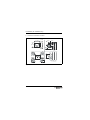
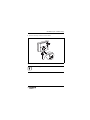
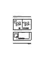
INSTALLATION & USER INSTRUCTIONS
INTELLIGENT ROOM THERMOSTAT
FR 10
6 720 617 760 (2008/09)
6 720 613 547-00.1R
FOR USE WITH THE FOLLOWING APPLIANCES:
GREENSTAR CDI COMBINATION BOILERS
GREENSTAR CDI SYSTEM BOILERS FITTED WITH OPTIONAL
INTEGRAL DIVERTER VALVE
GREENSTAR HIGHFLOW CDI COMBINATION BOILERS
Dear customer,
Dear customer,
Congratulations on having decided in favour of a top-quality product from our company.
The FR 10 offers everything you can expect from a modern heating
control: It is both reliable and energy saving.
Like all Bosch Group products, the FR 10 has been produced and
tested according to the most stringent quality standards so that
you can enjoy the Worcester warmth for a long time to come.
2
6 720 617 760 (2008/09)
Contents
Contents
1
Symbols and safety precautions . . . . . . . . . . . . . . . . . . . . 4
1.1 Symbols . . . . . . . . . . . . . . . . . . . . . . . . . . . . . . . . . . . 4
1.2 Safety precautions . . . . . . . . . . . . . . . . . . . . . . . . . . . 5
2
Technical data for the accessory item . . . . . . . . . . . . . . . .
2.1 Standard package . . . . . . . . . . . . . . . . . . . . . . . . . . .
2.2 Technical data . . . . . . . . . . . . . . . . . . . . . . . . . . . . . .
2.3 Supplementary accessories . . . . . . . . . . . . . . . . . . . .
2.4 Cleaning . . . . . . . . . . . . . . . . . . . . . . . . . . . . . . . . . . .
3
Installation (for installers only) . . . . . . . . . . . . . . . . . . . . . 9
3.1 Installation . . . . . . . . . . . . . . . . . . . . . . . . . . . . . . . . . 9
3.2 Disposal . . . . . . . . . . . . . . . . . . . . . . . . . . . . . . . . . . 13
3.3 Electrical connections . . . . . . . . . . . . . . . . . . . . . . . 13
4
Commissioning (for installers only) . . . . . . . . . . . . . . . . . 14
5
Operation . . . . . . . . . . . . . . . . . . . . . . . . . . . . . . . . . . . . .
5.1 Changing the operating mode . . . . . . . . . . . . . . . . .
5.2 Changing the required room temperature . . . . . . . .
5.3 Changing the standard setting of the required room
temperature . . . . . . . . . . . . . . . . . . . . . . . . . . . . . .
5.4 Adjusting the installer level (for installers only) . . .
5.5 Selecting the heating program . . . . . . . . . . . . . . . . .
5.6 Frost protection . . . . . . . . . . . . . . . . . . . . . . . . . . . .
6
7
7
8
8
15
17
17
18
19
23
23
6
Troubleshooting . . . . . . . . . . . . . . . . . . . . . . . . . . . . . . . . 24
7
Tips on saving energy . . . . . . . . . . . . . . . . . . . . . . . . . . . . 27
8
Environmental protection . . . . . . . . . . . . . . . . . . . . . . . . . 28
6 720 617 760 (2008/09)
3
Symbols and safety precautions
1
Symbols and safety precautions
1.1
Symbols
Safety instructions in this document are identified
by a warning triangle and are printed on a grey
background.
Signal words indicate the seriousness of the hazard in terms of the
consequences of not following the safety instructions.
•
Caution indicates that minor damage to property could result.
•
Warning indicates that minor personal injury or serious material losses could result.
•
Danger indicates that serious personal injury could result. In
particularly serious cases, lives could be at risk.
Notes are identified by the symbol shown on the
left. They are bordered by horizontal lines above
and below the text.
Notes contain important information in cases where there is no
risk of personal injury or material losses.
4
6 720 617 760 (2008/09)
Symbols and safety precautions
1.2
Safety precautions
B These instructions must be observed to ensure correct operation.
B Install and commission the boiler and all accessories in accordance with the associated instructions.
B Allow only qualified installers to install accessories.
B Only use these accessories in conjunction with the heating
appliances listed. Follow the connection diagram!
B Do not connect this accessory to the 230 V mains electricity
supply.
B Before installing these accessories:
Isolate the voltage supply (230 V AC) to the heating appliance
and all additional devices on the bus.
B Do not install this accessory in damp areas.
B Inform customers about the functions of accessories and
instruct them in their operation.
B When there is a risk of frost, leave the boiler switched on and
observe the frost protection information.
6 720 617 760 (2008/09)
5
Technical data for the accessory item
2
Technical data for the accessory
item
The FR 10 can only be connected to a boiler with
BUS-enabled Heatronic 3.
•
The FR 10 enables the room temperature control of a single
heating system.
•
The FR 10 must only be used in conjunction with a suitable
time switch, MT 10 or DT 20.
•
In systems with a single heating system, you can change automatically between the currently set operating mode
/
/
or heating operation off
using the time program of a time
switch.
•
The controller is designed for wall mounting.
6
6 720 617 760 (2008/09)
Technical data for the accessory item
Standard package
6 720 613 547-03.1R
2.1
1
2
Fig. 1
1
2
2.2
Top section, controller and base for wall mounting
Installation and operating instructions
Technical data
Dimensions
85 mm × 100 mm × 35 mm
H×W×D
Rated voltage
10 ... 24 V DC
Rated current
≤ 3.5 mA
Controller output
2-wire BUS
Control range
5 ... 30 °C in steps of 0.5 K
permiss. ambient temp.
0 ... +50 °C
Class of protection
III
Protection level
IP20
Tab. 1
6 720 617 760 (2008/09)
7
Technical data for the accessory item
2.3
Supplementary accessories
•
MT 10: Mechanical single channel time switch.
•
DT 20: Twin channel digital programmer.
2.4
Cleaning
B If required, use a damp cloth to wipe the controller casing.
Never use aggressive or acidic cleaning agents for this.
8
6 720 617 760 (2008/09)
Installation (for installers only)
3
Installation (for installers only)
DANGER: Risk of electric shock
B Before installing these accessories:
Isolate the voltage supply (230 V AC) to the heating appliance and all additional devices on the
bus.
3.1
Installation
The installation location must be suitable for controlling the heating system or heating circuit.
The accuracy of the FR 10 is dependent upon the installation location.
Any radiator in the same room as the FR 10 should not have a thermostatic radiator valve fitted.
The FR 10 should be installed so that the overall temperature of
the property is monitored, for example, hallways or landings and
not be installed in a living room or room with supplementary heating.
6 720 617 760 (2008/09)
9
Installation (for installers only)
B Select the installation location.
25 mm
100 mm
0,6 m
1,0 m
85 mm
0,75 m
1,2 m
35 mm
6 720 612 218-02.1J
Fig. 2
10
6 720 617 760 (2008/09)
Installation (for installers only)
B Remove the top section from the base.
3.
1.
2.
6 720 612 218-04.1R
Fig. 3
The mounting surface on the wall should be level.
6 720 617 760 (2008/09)
11
Installation (for installers only)
B Fit the base.
6 mm
3,5 mm
6 mm
3,5 mm
6 720 612 218-05.1R
Fig. 4
B Connect to the power supply.
Heatronic 3
FR 10
B B
ST 19
A F 1 2 4 B B
6 720 613 554-01.1R
Fig. 5
B Push on top section.
12
6 720 617 760 (2008/09)
Installation (for installers only)
3.2
Disposal
B Dispose of packaging in an environmentally responsible manner.
B When replacing components, dispose of the old parts in an
environmentally responsible manner.
3.3
Electrical connections
B BUS connection from the controller to other BUS subscribers:
Use electrical cable with the minimum specification H05 VV-...
(NYM-I...).
Permissible cable lengths from the BUS-enabled Heatronic 3 to
the controller:
Cable length
Cross-section
80 m
0.40 mm2
≤ 100 m
0.50 mm2
≤ 150 m
0.75 mm2
≤ 200 m
1.00 mm2
≤ 300 m
1.50 mm2
≤
Tab. 2
B To avoid inductive interference, lay all bus cables seperately to
lines of 230 V or 400 V (minimum spacing 100 mm).
B In case of external inductive interference, shield the cables.
This ensures that the cables are shielded from external interference (e.g. heavy current cables, overhead wires, transformer stations, radio and television set, amateur radio
stations, microwave ovens etc).
6 720 617 760 (2008/09)
13
Commissioning (for installers only)
4
Commissioning (for installers
only)
1 Switch on the system.
2 During first commissioning or after a global reset (resetting all
adjustments):
B Confirm the flashing code 1 HC by pressing
.
3 System configuration starts automatically, and lasts approximately. 60 seconds during which time AC will be displayed.
14
6 720 617 760 (2008/09)
Operation
Operation
6 720 613 554-02.1R
5
mode
1
2
Fig. 6
6 720 617 760 (2008/09)
15
Operation
Controls
1
Rotary selector
:
- Turn = Adjust value
- Press = Confirm setting/value
2
Mode key:
- Change operating mode
- Accessing user level = hold down for approx. 3 seconds
- Accessing installer level = Hold down for approx. 6 seconds
- Return to the higher level
Symbols
Current room temperature or required room temperature
(if the rotary selector is turned)
Operating mode Comfort (factory setting is 21 °C)
Operating mode Economy (factory setting is 15 °C)
Operating mode Frost (factory setting is 5 °C)
No heating operation available, e.g. heating mode off due to time
switch (accessory) or boiler
Burner operation
Tab. 3
Set the central heating temperature controller on
the boiler to maximum, to allow the FR 10 to be effective.
The FR 10 can only regulate the heating system if an operating
mode is enabled. In conjunction with a time switch (accessory),
the time program automatically changes between the currently
selected operating mode
/
/
and heating operation off .
Frost protection is safeguarded (Æ Chapter 5.6, page 23).
16
6 720 617 760 (2008/09)
Operation
5.1
Changing the operating mode
B Briefly press mode until the required operating mode is displayed.
= constant Comfort
= constant Economy
= constant Frost
The selected operating mode is only enabled if the heating
operation
is not blocked.
5.2
Changing the required room temperature
Use this function if you want to change the required
room temperature by way of an exception, e.g. for
the duration of a party.
B With rotary selector
adjust the required room temperature for the current operating mode
/
/ .
During this period, the required room temperature will flash
instead of the display showing the current room temperature.
The change to the required room temperature will remain in
force until the next operating mode change or until the power
is interrupted. At that point the system reverts to the room
temperature programmed at the user level for that particular
operating mode.
6 720 617 760 (2008/09)
17
Operation
5.3
Changing the standard setting of the required
room temperature
Use this function if you want to permanently change
the required room temperature away from the
standard setting.
B Accessing user level: Hold down mode for approx. 3 seconds
until – – is displayed.
B Release the mode key and turn
eter is shown:
until the required param-
– 1A p = Required room temperature for
Comfort
– 1b p = Required room temperature for
Economy
– 1C p = Required room temperature for
Frost
B Briefly press
: The current temperature for the previously
selected parameter will be displayed.
B Briefly press
B Turn
18
: The current temperature flashes.
to adjust the required room temperature:
–
Comfort = maximum required temperature (e.g. when
the living space is occupied and occupants require a comfortable room temperature). Setting range higher than
Economy up to 30 °C.
–
Economy = average required temperature (e.g. if a low
room temperature is adequate or if everyone is away or
asleep and the house should not cool down excessively). SetFrost and lower than
Comfort.
ting range higher than
–
Frost = minimum required temperature (e.g. if everyone
is away or asleep and the house should not cool down
excessively). Consider any pets and plants. Setting range
lower than
Economy down to 5 °C.
6 720 617 760 (2008/09)
Operation
B Briefly press
to save the value.
B Press mode until the current room temperature is displayed.
5.4
Adjusting the installer level (for installers
only)
The installer level is exclusively designed for installers.
B Accessing installer level: Hold down mode for approx. 6 seconds until – – – is displayed.
B Release the mode key and turn
eter is shown:
until the required param-
– 5A p = Code
– 5b p = Heating circuit configuration
– 6A p = Adjust the integral room temperature sensor
– 6b p = Adjustment factor I
– 6C p = Amplification factor V
– 6d p = Maximum flow temperature
– 6E p = Mixer runtime
B
Briefly press
: The current value for the previously
selected parameter is displayed.
B
Briefly press
B
Turn
: The current value flashes.
to select the required value.
B Briefly press
to save the value.
B Press mode until the current room temperature is displayed.
6 720 617 760 (2008/09)
19
Operation
5.4.1 Changing the code (parameter: 5A p)
Setting range: 1 to 10
Use this parameter if you want to adjust the code after commissioning:
B For systems with a single heating circuit: Select code 1.
Only one FR 10 can be used per heating system.
5.4.2 Changing the heating circuit configuration
(parameter: 5b p)
Setting range: 1 to 3
Use this parameter if you want to alter the configuration after
commissioning:
B Adjusting the corresponding configuration:
– 1 = unmixed heating circuit
– 2 = unmixed heating circuit with additional accessory
(not availabe in UK).
– 3 = mixed heating circuit
20
6 720 617 760 (2008/09)
Operation
5.4.3 Adjusting the room temperature sensor
(parameter: 6A p)
Setting range: – 3.0 °C (K) to +3.0 °C (K)
Use this parameter if you want to correct the displayed room temperature.
B Position a precision instrument near FR 10. The precision
instrument must not transfer any heat to the FR 10.
B Keep other heat sources, such as sunlight, body heat etc. away
for one hour.
B Adjust the displayed room temperature correction value.
5.4.4 Selecting adjustment factor I (parameter: 6b p)
Setting range: 0 % to 100 %
The adjustment factor I represents the speed with which the constant control deviation of the room temperature is compensated.
B Selecting adjustment factor I:
– ≤ 40 %: Select a lower factor to achieve slight room temperature overshoot through slow correction.
– ≥ 40 %: Select a higher factor to achieve a more rapid correction by a more severe room temperature overshoot.
6 720 617 760 (2008/09)
21
Operation
5.4.5 Selecting amplification factor V (parameter: 6C p)
Setting range: 40 % to 100 %
Subject to changes in room temperature, the amplification factor
V influences the heat demand.
B Selecting amplification factor V:
– ≤ 50 %: Select a lower factor to reduce the influence on the
heat demand. The selected room temperature is achieved
after a longer time with only little overshoot.
– ≥ 50 %: Select a higher factor to increase the influence on
the heat demand. The selected room temperature is
achieved quickly with a tendency towards overshooting.
5.4.6 Selecting the maximum flow temperature
(parameter: 6d p)
Setting range: 30 °C to 85 °C
B Select the flow temperature to suit the heating circuit.
5.4.7 Selecting the mixer runtime (parameter: 6E p)
Setting range: 10 s to 600 s
5.4.8 Resetting all adjustments
This function returns all controller settings and adjustments to their standard settings. Following
such a reset, your installer will need to commission
the controller again.
B Hold down
and mode simultaneously for 15 seconds until
the countdown function has expired.
22
6 720 617 760 (2008/09)
Operation
5.5
Selecting the heating program
B Select the heating program with start and stop switching times
at the time switch (Æ time switch operating instructions).
5.6
Frost protection
The heating (circuit pump) starts if the room temperature in the
room where the FR 10 is installed falls below 4 °C or the flow
temperature falls below 8 °C. The heating system is started and
stopped accordingly to maintain the room temperature of 4 °C or
the flow temperature of 8 °C.
6 720 617 760 (2008/09)
23
Troubleshooting
6
Troubleshooting
If the boiler has developed a fault, the display will show, for example, EA. E. Here, EA means a boiler fault; the full stop . means an
external fault; E means error (= fault).
If the FR 10 has developed a fault, the display will show, for example, 03 E.
Here, 03 refers the the fault number at the FR 10 and E stands for
error (= fault):
B Contact your installer.
If several faults are active, the fault with the highest priority is displayed.
Display
Cause
01 E
Boiler no longer reporting. Check codes and connection of
BUS subscribers.
Remedy (by installer)
Incorrect BUS subscriber
connected.
Replace incorrect BUS subscriber.
02 E
Internal fault.
Replace FR 10.
03 E
Temperature sensor in
FR 10 faulty.
Replace FR 10.
11 E
New BUS subscriber recognised.
Check and adjust configuration.
12 E
BUS subscriber IPM missing.
Check codes and connection of
BUS subscribers.
13 E
BUS subscriber changed
or replaced.
Check and adjust configuration,
codes and connections.
14 E
Inadmissible BUS subscriber connected.
Remove inadmissible BUS subscriber.
AE. E
...
Boiler fault.
Correct the fault in accordance
with the details in the boiler documentation.
Tab. 4
24
6 720 617 760 (2008/09)
Troubleshooting
Fault
Cause
Remedy
Required room
temperature not
achieved.
Thermostatic valve(s) are
not opened sufficiently.
Fully open the thermostatic valve(s) or ask
your installer to check
the valves.
Central heating temperature Set the central heating
control on the boiler set too temperature controll
low.
higher.
Air in the heating system.
Bleed radiators and vent
the heating system.
Required room
FR 10 installed in an unfatemperature
vourable location, e.g. extergreatly exceeded. nal wall, near windows, in a
draught etc.
Select a better location
(Æ Chapter 3.1) and ask
your installer to relocate
FR 10.
Excessive room
Temporary influence of
temperature fluc- external heat on the room,
tuations.
e.g. through insulation, solar
gain, lighting, TV, fireplace
etc.
Select a better location
(Æ Chapter 3.1) and ask
your installer to relocate
FR 10.
Temperature
rises instead of
falling.
Time incorrectly set at the
time switch (accessory).
Check time setting.
Room temperature excessively
high during OFF
period.
The building retains a lot of
heat.
Select an earlier stop
time on the time switch
(accessory).
Incorrect or
nocontrol.
BUS connection of BUS sub- Ask your installer to
scriber faulty.
check the BUS connection and correct if
required, in accordance
with the connection diagram.
Tab. 5
6 720 617 760 (2008/09)
25
Troubleshooting
If the fault persists:
B Call your installer or customer service and inform them of the
fault, quoting the appliance details (from the type plate).
Appliance details
Type:
........................................................................................................
Part number:
........................................................................................................
Date of manufacture (FD...):
........................................................................................................
26
6 720 617 760 (2008/09)
Tips on saving energy
7
Tips on saving energy
•
Regulate the temperature in adjacent rooms via thermostatic
valves.
•
External heat in the room where th FR 10 is installed (e.g. solar
gain, stove etc.) can result in too little heating in adjacent
rooms (the heating system remains cold).
•
Much energy can be saved by reducing the room temperature
via economy phases. Reducing the room temperature by
1 K ( °C) enables up to 5% energy to be saved.
It is not recommended to let the room temperature of heated
rooms fall below +15 °C during the daytime, otherwise the
cooled-down walls continue to radiate cold and the room temperature rises higher, leading to higher energy consumption
than if an even heat supply is applied.
•
Good thermal insulation of the building: The set temperature
for
Economy or
Frost is never reached. Nevertheless
energy is being saved as the heating system stays off.In that
case, switch sooner to the lower operating mode.
•
Don't keep windows slightly open for ventilation. This leads to
a constant extraction of heat from the room without noticeably
improving the ambient air in the room.
•
Vent briefly but intensively (open window fully).
•
During venting shut off thermostatic valves fully or switch the
operating mode to Frost.
6 720 617 760 (2008/09)
27
Environmental protection
8
Environmental protection
Environmental protection is a fundamental corporate strategy of
the Bosch Group.
The quality of our products, their economy and environmental
safety are all of equal importance to us and all environmental protection legislation and regulations are strictly observed.
We use the best possible technology and materials for protecting
the environment taking account of economic considerations.
Packaging
We participate in the recycling programmes of the countries in
which our products are sold to ensure optimum recycling.
All of our packaging materials are environmental-friendly and can
be recycled.
Used appliances
Used appliances contain valuable materials that should be recycled.
The various assemblies can be easily dismantled and synthetic
materials are marked accordingly. Assemblies can therefore be
sorted by composition and passed on for recycling or disposal.
28
6 720 617 760 (2008/09)
Notes
6 720 617 760 (2008/09)
29
Notes
30
6 720 617 760 (2008/09)
Notes
6 720 617 760 (2008/09)
31
067206177608
CONTACT INFORMATION
WORCESTER, BOSCH GROUP:
TECHNICAL:
08705 266241
SERVICE:
08457 256206
SPARES:
01905 752571
LITERATURE:
01905 752556
TRAINING:
01905 752526
SALES:
01905 752640
WEBSITE: www.worcester-bosch.co.uk
Dedicated to heating comfort
Worcester, Bosch Group
Cotswold Way, Warndon, Worcester WR4 9SW
Tel. 01905 754624 Fax. 01905 754619
Worcester, Bosch Group is a brand name of
Bosch Thermotechnology Ltd.
www.worcester-bosch.co.uk