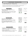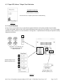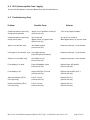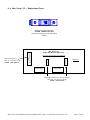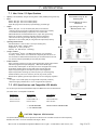
1
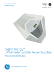
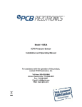
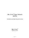
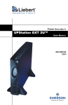
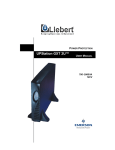
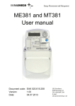
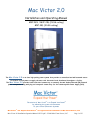
Mac Victor 2.0
Installation and Operating Manual
MVP-2KS / MVP-2KL (2 kVA rating)
MVP-3KL (3 kVA rating)
Victor
an ultra
quality
power
system
provides
centralized
and
wall
mounted
The The
MacMac
Victor
2.0 2.0
is anisultra
high high
quality
power
system
thatthat
provides
a centralized
and
wall
mounted
source
source
for
mission
critical
power
to
supply
the
most
vital
electronic
loads
distributed
throughout
a
for mission critical power to supply the most vital electronic loads distributed throughout a facility.
facility.
The 2.0
Macprovides
Victorboth
2.0 hard
provides
hard wired
to remotely
located
The Mac
Victor
wiredboth
connectivity
to connectivity
remotely located
Isolated
GroundIsolated
(IG) network
Ground
(IG)
network
power
receptacles
along
with
plug
and
receptacle
connectivity
for
the
Uninterruptible
power receptacles along with plug and receptacle connectivity for the Uninterruptible Power Supply (UPS).
Power Supply (UPS).
The mission of Mac Victor® is to Expand Your Power®
by enhancing the return on investment
of your Critical Electronic Systems
Mac Victor® and Expand Your Power® are registered U.S. trademarks of Mac Victor Power, LLC
Mac Victor 2.0 Installation Operation Manual 120711.pdf - © 2008 Mac Victor Power, LLC.
Page 1 of 23
Mac Victor 2.0 (Installation and Operating Manual)
CONTENTS
1
IMPORTANT SAFETY INSTRUCTIONS …………………………………………………………………… 3
2
PRODUCT OVERVIEW …………………………………………………………………………………………………… 5
3
OPTIONS / ACCESSORIES …………………………………………………………………………………………… 8
4
INSTALLATION ……………………………………………………………………………………………………………… 9
5
STARTUP / OPERATION ……………………………………………………………………………………………… 14
6
MAINTENANCE/TROUBLESHOOTING …………………………………………………………………… 18
7
SPECIFICATIONS ………………………………………………………………………………………………………… 22
1.1
1.2
1.3
1.4
1.5
2.1
2.2
2.3
2.4
2.5
2.6
Save these instructions
General
Installation
UPS Batteries
Transport / Storage
Operating Schematic
Theory of Operation
System Benefits
Description of Operation
Component Diagram
Item numbers with Options
3.1 Mac Victor 2.0 Options
3.2 Mac Victor Power Strip Accessories
4.1
4.2
4.3
4.4
4.5
4.6
4.7
4.8
5.1
5.2
5.3
5.4
6.1
6.2
6.3
6.4
6.5
6.6
Package Contents
Location
Typical Elevation
Mounting Instructions
Wiring Diagram – Mac Victor 2.0
Wiring Diagram – Remote Power Off
Wiring Diagram – Remote signaling of Input and Output power status
Wiring Diagram – Optional 5th Circuit IG Outlet and Optional Remote Off
Power up of the Mac Victor 2.0
Installation and Strapping of the UPS
Power up of the UPS
Surge Monitoring Operation
Input & Output Pilot Lights / UPS Bypass Switch
Input SPD Alarm / Output Fuse Indication
Circuit Breakers
UPS (Uninterruptible Power Supply)
Troubleshooting Chart
Mac Victor 2.0 Replacement Parts
7.1 Mac Victor 2.0 Specifications
7.2 UPS Specifications and Compatible UPS Models
Mac Victor 2.0 Installation Operation Manual 120711.pdf - © 2008 Mac Victor Power, LLC.
Page 2 of 23
1 - IMPORTANT SAFETY INSTRUCTIONS
1.1 Save these Instructions
This manual contains important instructions and specifications for the Mac Victor 2.0 that should be
followed during installation and maintenance.
CAUTION: Risk of Personal Injury and Equipment Damage.
Before attempting to install and power up the Mac Victor 2.0, carefully read
this manual. Keep this manual with the Mac Victor 2.0 for future references.
All service work must be done by qualified personnel. Do not attempt to
service the Mac Victor 2.0 unless you have had proper training.
WARNING: Risk of Electrical Shock and Personal Injury. Opening or
removing covers risk the exposure to dangerous voltages!
While every effort has been made to ensure the completeness and accuracy of this manual,
Mac Victor Power, LLC and THOR SYSTEMS, Inc. accept no responsibility or liability for
any loss or damage resulting from the use of the information contained in this document.
This complete document shall not be copied or reproduced without the written permission
of Mac Victor Power, LLC. Due to technical improvements, some of the information
contained in this manual may be changed without notice.
1.2 General
•
•
•
•
•
•
WARNING: RISK OF ELECTRICAL SHOCK AND PERSONAL INJURY.
More than one Disconnect Switch may be required to de-energize the equipment before
servicing. Service is to be performed by qualified personnel only!
See Installation Instructions before connecting to the supply.
The Mac Victor 2.0 provides plug and receptacle interfacing with selected models of
Uninterruptible Power Supplies (hereafter UPS) manufactured by others. See the
accompanying UPS Installation Instructions before connecting to the supply. All UPS that are
used must be “Mac Victor 2.0 Compatible UPS”. (See Section 7.2 for list of Compatible UPS)
All UPS units have internal batteries as part of the product package. Dangerous voltages may
still be present even when all external voltage sources have been de-energized.
The UPS should be bypassed, turned off and disconnected during maintenance or service work.
1.3 Installation
•
•
•
•
•
•
The Mac Victor 2.0 base unit should be installed by a licensed electrical contractor.
The UPS can be installed and started up by qualified office technical personnel.
To reduce the risk of electric shock, install the Mac Victor 2.0 and the UPS in a temperature
and humidity controlled indoor area free of conductive contaminants.
Ambient temperature must not exceed 30ºC (86ºF). Optimal battery life of peripheral UPS is
also obtained if the ambient temperature does not exceed 30ºC (86ºF).
It is important that both the Mac Victor 2.0 and the UPS have adequate ventilation. Maintain
air movement around and through the units. Do not block the air vents.
Avoid installing the units in direct sunlight or near heat sources.
Mac Victor 2.0 Installation Operation Manual 120711.pdf - © 2008 Mac Victor Power, LLC.
Page 3 of 23
•
•
•
•
•
•
•
•
•
•
•
It is important to install the Mac Victor 2.0 in a location that provides adequate space above
the unit for the later installation of the UPS. See the UPS Installation and Operating Manual
for the critical dimensions.
Both the Mac Victor 2.0 and the UPS should be positioned to insure that there is a minimum of
36 inches (3 feet) full front clearance for service and maintenance.
The Mac Victor 2.0 should only be powered from a hard wired 120Vac, 60 Hz, single phase
source of supply. See installation instructions for proper sizing depending on the model used.
The UPS provides battery backup for the network and is powered by a factory installed,
grounded receptacle and overcurrent protection that is part of the Mac Victor 2.0 integrated
system. The UPS must be “Mac Victor 2.0 Compatible UPS”. (See Section 7.2 for list of
Compatible UPS)
The UPS should never be disconnected from the Mac Victor receptacle while under load.
The factory installed Mac Victor plug assembly is intended to be plugged into the UPS output
supply using one of the available UPS outlets. Do not plug the Mac Victor plug assembly into any
other outlets except for the UPS outlets.
Do not plug other equipment into the other UPS outlets except for the Mac Victor 2.0 plug
assembly. Equipment plugged into the other UPS outlets will not function in the bypass mode
and will not receive maximum power protection from the system.
Avoid spilling liquids on or dropping any foreign object onto the Mac Victor 2.0 or the UPS.
Do not plug a laser printer or other household appliances such as electric heaters or vacuum
cleaners into the UPS, the Mac Victor 2.0 accessory Isolated Ground outlets, or other remotely
located Isolated Ground outlets that are connected. These devices can overload both units and
cause the circuit breakers to trip resulting in system shutdown.
To prevent unauthorized equipment from being plugged in, it is recommended that any open
Isolated Ground outlets that are part of the Mac Victor 2.0 should be covered with safety
outlet protector plugs (included).
The Mac Victor 2.0 should be serviced by trained electrical personnel.
1.4 UPS Batteries
•
The UPS Manufacturer’s Installation and Operating Manual should be consulted for all
references to the proper replacement, handling, storage, and disposal of UPS batteries.
1.5 Transport / Storage
•
•
No liability will be accepted for any transport damage when the Mac Victor 2.0 units are
shipped in non-original packaging.
Store the Mac Victor 2.0 units in a dry location. Storage temperature must be within a range
of -15ºC to 50ºC (5ºF to 122ºF)
Mac Victor 2.0 Installation Operation Manual 120711.pdf - © 2008 Mac Victor Power, LLC.
Page 4 of 23
2 – PRODUCT OVERVIEW
Figure 2.1
2.1 Operating Schematic
The above Mac Victor 2.0 Operating Schematic provides a conceptual diagram of the system operation and does
not represent an actual wiring diagram. See Section 2.4 for a Description of Operation.
2.2 Theory of Operation
Isolated Ground (hereafter IG) receptacles (identified by their orange color or an orange triangle) are used with
critical electronic systems to provide a separate, isolated ground reference point (for data communication and
logic) from the safety or equipment ground required to protect the circuit from over current faults.
Typically, the IG conductors are run back to the electrical main service entrance grounding terminal of the
facility, which can result in electrical disturbances on the IG conductor caused by induced voltages from other
parallel conductors run in the same conduits, raceways and panelboards. This practice can effectively defeat the
purpose of the IG receptacles by injecting electrical noise onto the IG conductor.
The National Electrical Code (NEC) allows for an alternative IG grounding method through the use of a “separately
derived system” such as an isolation transformer that allows for the re-establishment of the Neutral to Ground
bond on the output wiring. This Neutral to Ground bond, also known as a newly derived Neutral, provides an
acceptable location to terminate the IG conductor in lieu of wiring back to the main service entrance grounding
terminal.
The Mac Victor 2.0 constitutes a “separately derived system” because of the internal, low impedance, isolation
transformer that has the Neutral and Ground output wiring bonded together. All the conductors associated with
the installation of IG receptacles (Line, Neutral, Ground, Isolated Ground) are designed to terminate at the Mac
Victor 2.0 which is also designed to interface with plug and receptacle connections with the Uninterruptible Power
Supply (UPS) that provides battery backup for the network.
The Mac Victor 2.0 therefore provides a centralized system with both “clean” isolated ground power and battery
backup power for critical electronic networks in addition to many other operational and maintenance benefits.
Mac Victor 2.0 Installation Operation Manual 120711.pdf - © 2008 Mac Victor Power, LLC.
Page 5 of 23
2.3 System Benefits
• Provides clean and continuous power for critical electronic systems to minimize downtime and lost revenue
associated with computer lockups, data losses, hardware failures and power outages.
• Centralized, wall mounted design saves valuable floor space and is easier to maintain and manage.
• Eliminates the need for all remote plug in battery backups, filters, power conditioners, and surge strips which
saves under counter / desktop space.
• Assures that all connected equipment is on the same electrical phase of power for better data communication.
• UPS Bypass Switch (make before break) provides seamless power during UPS maintenance
• Input and output power pilot lights provide for status indication and ease of troubleshooting
2.4 Description of Operation
• 120 Vac, 1 Phase input power supplied to Mac Victor 2.0 from remote supply (20A for 2kVA or 30A for 3kVA circuit)
• Input circuit breaker provides overcurrent protection for Mac Victor 2.0 (20A for 2kVA or 30A for 3kVA circuit)
• Input Surge Protection Device (hereafter SPD) replaceable module protects Mac Victor 2.0 from surges
• Front Panel mounted Monitor detects open fuses on both Input SPD & Output Surge & Filter Board Assembly
• Input power status light is illuminated when the input circuit breaker is turned on
• Power routed within Mac Victor 2.0 to the Normal / Bypass transfer switch
• In Normal mode:
• Power routed from Normal/Bypass switch to the Mac Victor 2.0 Power receptacle and UPS plug assembly
• UPS provides 120 Vac output with battery backup to UPS receptacle
• Mac Victor 2.0 plug assembly connects to UPS receptacle and returns power back to the Mac Victor 2.0
• Power routed through remote power off relay to the Isolation Transformer with neutral to ground bond
• Output Surge & filter board assembly provides additional surge power protection and noise filtering
• Output Surge & filter board assembly provides signal relays for Input and Output Power remote status
• Output Surge & filter board assembly provides supply power & fuse status signal to panel monitor
• Output power status pilot light is illuminated
• Power routed to 4 output circuit breakers and terminals for field wiring to remote IG power circuits
• (Optional) Power routed to 1 output circuit breaker that powers 4 fully integrated IG receptacle outlets
• (Optional) Remote power off shutdown relay can be added for the integrated IG receptacles
• Mac Victor 2.0 provides dedicated, fully isolated, battery backup source to remote hardwired Isolated
Ground (IG) receptacles and other hard wired equipment
• In Bypass Mode:
• Power is routed from Normal / Bypass switch directly to remote power off relay, bypassing the UPS
• Power is disconnected from the Mac Victor 2.0 Power Plug assembly in the bypass mode
• Output power status pilot light remains illuminated and does not flicker during the transfer since the
switch has “make before break” capability
• Power is routed through the isolation transformer and through the circuit breakers to the isolated ground
receptacles the same as in the Normal Mode operation
• In Remote Power Off (RPO) Mode:
• RPO function is enabled when a jumper feeding the coil of the Remote Power Off relay is removed and
replaced with wiring to the maintained normally closed (N/C) contacts of a Remote Power Off switch.
• When the RPO switch is activated input power feeding the isolation transformer is disconnected by the relay
on both the Line and Neutral conductors which removes power from the IG receptacles and equipment
• When the RPO switch is deactivated input power feeding the isolation transformer is reconnected by the
relay which restores power to the IG receptacles and equipment
Mac Victor 2.0 Installation Operation Manual 120711.pdf - © 2008 Mac Victor Power, LLC.
Page 6 of 23
2.5 Component Diagram
Figure 2.2
2.6 Item numbers with Options
Item numbers are comprised of one of the three Base Item Numbers with the addition of one or more Optional
Item Suffixes added to the end of the Base Item Number. Multiple suffixes can be used for additional options.
See Section 3 for more information about the available Options and other Accessory items.
Example: 2kVA Mac Victor 2.0 Base unit w/ locking blade UPS connectors & Optional 5th breaker w/ IG outlets
Item Number = MVP-2KL-IG
Base Item Number
Description
MVP-2KS
2kVA – Mac Victor 2.0 w/ straight blade UPS receptacle (NEMA 5-20P or L5-20P / 5-20R)
MVP-2KL
2kVA – Mac Victor 2.0 w/ locking blade UPS connectors (NEMA L5-20P / L5-20R)
MVP-3KL
3kVA – Mac Victor 2.0 w/ locking blade UPS connectors (NEMA L5-30P / L5-30R)
MVP-3KL-1B
3kVA – Mac Victor 2.0 w/ locking blade UPS connectors (NEMA L5-30P / L5-30R) with a
single 30 amp output breaker for wiring to panel board or control panel
Option Item Suffix
Description
Add suffix - IG
Optional 5th output circuit breaker and integrated Isolated Ground receptacles (4 outlets total)
Add suffix - ES
Optional Remote power off shutdown relay added for the integrated Isolated Ground receptacles.
(must be ordered along with the –IG option)
Uninterruptible Power Supplies (UPS) that mount on top of the Mac Victor 2.0 base units must be ordered
separately and must be “Mac Victor 2.0 Compatible UPS”. See Section 7.2 for a list of Compatible UPS models.
Mac Victor 2.0 Installation Operation Manual 120711.pdf - © 2008 Mac Victor Power, LLC.
Page 7 of 23
3 – OPTIONS / ACCESSORIES
3.1 Mac Victor 2.0 Options
These Mac Victor 2.0 optional features are available with the MVP-2KS, MVP-2KL, and MVP-3KL base units. See
complete part number listing in Section 2.6.
-IG Suffix (Isolated Ground receptacle option)
Integrated Isolated Ground Receptacles Option (-IG suffix) – includes 4 outlets
and a 5th output circuit breaker.
Mac Victor 2.0
(Left hand side view)
The Integrated Isolated Ground Receptacle Option and breaker are located on the
left hand side of the cabinet. NOTE: When using this option, it may be necessary
to remove the left hand side panel (5 screws) to improve access to the ground bars.
-ES Suffix (Emergency Shutdown for the -IG Suffix option)
Emergency Shutdown Option (-ES suffix) for the Integrated Isolated Ground
receptacles. Used in gasoline fueling applications to shut down data boxes that are
part of the fueling system during emergency shutdown.
Includes the addition of a relay and terminal strips that are factory wired inside the
cabinet. (Must be ordered along with the –IG option.)
Figure 3.1
3.2 Mac Victor Power Strip Accessories
The Mac Victor 2.0 also has accessory U.L. Listed factory assembled, pre-wired Isolated Ground power strips that
are available in 4 outlet and 10 outlet configurations. Mac Victor Power Strips must be ordered separately.
Important Note: Installation of the Mac Victor Power Strips shall comply with the latest revision of the
National Electrical Code (NEC), NFPA 70.
Figure 3.2
Mac Victor 2.0 Installation Operation Manual 120711.pdf - © 2008 Mac Victor Power, LLC.
Page 8 of 23
4 – INSTALLATION
4.1 Package Contents
The packing box contains a Mac Victor 2.0, mounting hardware (wood stud mount only), a circuit polarity plug
tester, safety outlet protector plugs (12), UPS strapping materials, and this Installation and Operating Manual.
Carefully inspect all the contents. If any damage is visible immediately notify the carrier and the shipper.
4.2 Location
Please refer to Section 1.3 of the Important Safety Instructions regarding installation. Typical wall mounted
locations include the manager’s office, electrical room or closet, telecom equipment wall, datacom room, or other
secure locations that are not accessible to the public.
To minimize the distance of branch circuit runs to the remote Isolated Ground receptacles, choose a relatively
central location if possible to mount the Mac Victor 2.0.
A location relatively close to a circuit breaker panel is also preferred since a single 120Vac, single phase circuit
(Line, Neutral, and Ground) must be run to feed the input terminals of the Mac Victor 2.0.
Allow for UPS mounting height on top of the Mac Victor 2.0 when locating the height of installation.
4.3 Typical Elevation
The Mac Victor 2.0 Typical Elevation below provides a conceptual diagram of a typical wall mounted elevation that
shows the overall enclosure dimensions and typical input and output power wiring.
Figure 4.1 – Mac Victor 2.0 Elevation
Mac Victor 2.0 Installation Operation Manual 120711.pdf - © 2008 Mac Victor Power, LLC.
Page 9 of 23
4.4 Mounting Instructions
•
•
•
•
•
CAUTION – Improper installation can result in serious personal injury. Make sure the mounting surface
can support a redundant weight factor five times the total weight of the equipment. If not, reinforce
the structure before installation of the Mac Victor 2.0
CAUTION – Improper installation can result in equipment damage. The installer is responsible for
verifying that the installation wall will safely support the combined load of the Mac Victor 2.0 and the
top mounted UPS (if applicable)
CAUTION – The combined weight of the Mac Victor 2.0 and the UPS on top must not exceed 200 lbs
CAUTION – Watch for pinch points. Do not put your fingers between moving parts such as the hinged,
front door and the latches.
WARNING – Install, wire, power up, and test the Mac Victor 2.0 completely before the installation of
the UPS battery backup which is detailed in Section 5.
Figure 4.2
Parts Required (Wood Stud Mount)
•
•
2 - Lag bolts (5/16” x 3½”) – included
2 – Flat washers (5/16”) – included
Tools Required
•
•
•
•
Electric drill and drill bit set
Socket wrench set
Level and marking device
Misc hand tools – hammer, screwdrivers, etc.
3/8” Mounting holes
Quantity (2)
Back Dimensions;
Wall Mount
Installation Steps (Wood Stud Mounting)
1.
Locate 2 adjacent wooden studs (16” on center) at the desired installation location.
2.
BE SURE TO ACCOUNT FOR THE HEIGHT OF THE UPS TO BE INSTALLED ON TOP OF THE MAC VICTOR 2.0 SHELF WHEN
DETERMINING THE MOUNTING LOCATION.
3.
Determine the desired mounting height and mark on the wall (centered on one of the wood studs) the desired location of the top of the Mac Victor
2.0 enclosure (not including the mounting shelf flanges).
4.
From this mark drop down 2 1/8” and make another mark on the wall. This is the location of one of the top two mounting holes.
5.
Use a level from this mark to make a second mark a distance of 16” to the center of the adjacent wood stud. This is the location of the 2nd
mounting hole.
6.
Drill 2 pilot holes on the centerline wood stud marks using a 3/16” bit approximately 3” deep through the wall and into the wood studs.
7.
Carefully lift the Mac Victor 2.0 enclosure so that the 3/8” mounting holes shown in Figure 4.2 line up with the pilot holes drilled in Step 6.
8.
Install the supplied 2 - 5/16” x 3 ½” lag bolts and 2 - 5/16” flat washers through the two mounting holes and into the wood studs using a socket
wrench.
9.
At this point, the Mac Victor 2.0 should hang freely on the wall.
10. Check the 2 lag bolts to insure they are fully and securely tightened.
Mac Victor 2.0 Installation Operation Manual 120711.pdf - © 2008 Mac Victor Power, LLC.
Page 10 of 23
4.5 Wiring Diagram – Mac Victor 2.0
The below Mac Victor 2.0 Wiring Diagram provides the input and output wiring terminals for proper installation.
The factory wiring and other wiring components are not shown for the sake of simplicity. Follow these wiring
diagrams exactly and do not modify any factory wiring or other wiring components.
Mac Victor 2.0 / Wiring Diagram
Figure 4.3
Output Power Terminals
(TS – 2)
Typical Isolated Ground
(IG) receptacle
wired to Circuit #1
120Vac, 1 Phase, 60hz
(see chart below for
circuit breaker sizing)
Input Power Terminals
(TS – 1)
Remote Input
Circuit Breaker
#12 AWG
Black
Black
Circuit #1 Line
Circuit #2 Line
Circuit #3 Line
White
Circuit #4 Line
Circuit #5 Line
#12 AWG
White
Circuit #1 Neutral
Green
Circuit #2 Neutral
Circuit #3 Neutral
Circuit #4 Neutral
3kVA Models
Breaker = 30A
Wiring = #10 AWG
Equipment
Ground Bar
Isolated
Ground Bar
OPTIONAL: only
when required by
local Electrical AHJ
Remote Power Off Relay & Jumper
(See Section 4.6)
Input SPD module
#4 AWG
#12 AWG
Green with
Yellow Stripe
Ground Bar
2kVA Models
Breaker = 20A
Wiring = #12 AWG
Circuit #5 Neutral
#12 AWG
Green
Neutral Bar
Grounding
Electrode
System
THOR#: TSi040R-150-1P10
(Includes mounting base
and replacement module)
Input / Output Power Status
(See Section 4.7)
Notes:
•
•
•
•
•
•
•
WARNING: RISK OF ELECTRICAL SHOCK AND PERSONAL INJURY.
Dashed lines indicate field wiring
Remote Input Circuit Breaker wiring must be run in separate conduit from all output wiring
All output wiring must be run in dedicated conduits or MC cable and not routed with any
other equipment wiring to avoid induced voltages.
Replace the Input SPD module if the front panel surge monitor goes into alarm condition
See Section 4.6 for the wiring diagram for the Remote Power Off function
See Section 4.7 for the wiring diagram for the Input / Output Power Status function
Mac Victor 2.0 Installation Operation Manual 120711.pdf - © 2008 Mac Victor Power, LLC.
Page 11 of 23
4.6 Wiring Diagram – Remote Power Off
This Mac Victor 2.0 standard feature is for the manual shutdown of all Mac Victor 2.0 output power via an
externally mounted Remote Power Off switch. Use only when required by the local Authority Having Jurisdiction
(AHJ).
Figure 4.4
Input Power Terminals
(TS – 1)
Remove factory jumper and install
Remote Power Off Switch
(N/C contacts)
Remote Power Off Switch
(maintained N/C contacts)
Toggle Switch or
Push / Pull Switch or
N/C relay contacts
Remote Power Off Relay (R1)
* Open for shutdown
* Close to restore power
4.7 Wiring Diagram – Remote signaling of Input and Output power status
This Mac Victor 2.0 standard feature provides the ability to provide dry contact relay signals (form C type) for
both the Input Power status and the Output Power status. This signaling can be used to operate remotely located
power status pilot lights or to provide dry contact status signals to the inputs of Building Automation Systems.
Figure 4.5
Power Status Terminal Blocks (11 – 16 on TS-1))
Input Power ON = terminals 11 to 12 are open
terminals 12 to 13 are closed
Input Power OFF = terminals 11 to 12 are closed
Input Power Terminals
(TS – 1)
terminals 12 to 13 are open
Output Power ON = terminals 14 to 15 are open
terminals 15 to 16 are closed
Output Power OFF = terminals 14 to 15 are closed
terminals 15 to 16 are open
Relay TB-2
Relay TB-1
Relay Specifications (TB-1 & TB-2):
Maximum contact rating (per relay)
1/10 amp at 120Vac
Mac Victor 2.0 Installation Operation Manual 120711.pdf - © 2008 Mac Victor Power, LLC.
Page 12 of 23
4.8 Wiring Diagram – Optional 5th Circuit IG Outlet and Optional Remote Off
This Mac Victor 2.0 optional feature is for manual shutdown of just the optional Isolated Ground outlet power
(left hand side of cabinet) only when required by the local Authority Having Jurisdiction (AHJ) and only in gasoline
fueling applications. These special applications can have fueling data boxes plugged into the IG outlets that may
need to be shut down during fueling emergencies. This option disconnects both Line and Neutral wiring.
Figure 4.6
Input Power Terminals
(TS – 1)
Remote Power Off Relay (R2) for
Circuit #5 IG Outlets (Optional)
Remote Power Source for
emergency shutdown of
gasoline fueling system.
(maintained N/C contacts)
Remove factory jumper and install
Remote Power Off Switch
(N/C contacts)
Toggle Switch or
Push / Pull Switch or
N/C relay contacts
* Open for shutdown
* Close to restore power
Mac Victor 2.0 Installation Operation Manual 120711.pdf - © 2008 Mac Victor Power, LLC.
Page 13 of 23
5 – STARTUP / OPERATION
5.1 Power up of the Mac Victor 2.0
•
WARNING: RISK OF ELECTRICAL SHOCK AND PERSONAL INJURY
•
Do not install the UPS until the startup of the Mac Victor 2.0 system is completed.
1.
Turn off all input and output circuit breakers / Set the UPS Bypass Switch to the “Normal” position
2. Verify all the wiring connections are correct per Sections 4.5 – 4.8
3. Turn on the remote circuit breaker feeding the Mac Victor 2.0 and test for 120Vac on voltage input terminals
(TS-1 terminals L and N). Verify proper grounding on the input terminal strip (TS-1 terminal G)
4. Close and latch the front hinged enclosure cover
5. Turn on the input power circuit breaker (MB-1) located at the lower front right of the enclosure
6. The “Input Power” pilot should come on.
7. Set the UPS Bypass Switch to the “Bypass” position
8. The “Output Power” pilot should come on / The SPD Monitor should also come on.
9. Turn on the output circuit breakers #1 – #4. If the integrated IG receptacle option is used, turn on circuit
breaker #5 which is on the left hand side of the enclosure.
10. Test the remote IG receptacles that are wired to the output terminals with the Circuit Polarity Plug Tester
(included) to verify correct wiring of the IG receptacles.
11. Plug in the selected electronic equipment to the remote IG receptacles and the optional integrated IG outlets.
12. Insert the Safety Outlet Protector Plugs (included) on all remaining open outlets on the IG receptacles.
Figure 5.1
Mac Victor 2.0 Installation Operation Manual 120711.pdf - © 2008 Mac Victor Power, LLC.
Page 14 of 23
5.2 Installation and Strapping of the UPS
•
CAUTION: RISK OF PERSONAL INJURY AND EQUIPMENT DAMAGE.
1.
The strapping of the UPS to the Mac Victor 2.0 shelf is strongly recommended before the UPS has been
started up and is fully operational. Strapping requirements may vary for different localities so consult
with the local Authority Having Jurisdiction (AHJ) for specific strapping requirements and / or materials.
2. The Mac Victor 2.0 has an integrated UPS shelf with total of 4 strapping slots (2 front and 2 back) to
accommodate the installation of 2 separate straps.
3. Mount the UPS on top of the Mac Victor 2.0 Shelf with the front of the UPS facing to the left (outlets
and power cord facing the right)
4. The UPS should be located on the shelf in a position that insures adequate rear ventilation of the UPS
(surface facing the back wall) according to the UPS Manual. Do not block the UPS ventilation holes.
5. The Mac Victor 2.0 comes with 2 – 8’ straps (½” wide polypropylene - 600 lb rated), 2 wire buckles, and 4
edge protectors for use on top of the UPS. Install the 2 sets of strapping, edge protectors, and wire
buckles as shown in Figure 5.3 to secure the UPS.
Edge Protectors (4)
Figure 5.3
UPS
(Right hand side view)
8.6” maximum
Wire Buckle (2)
Uninterruptible Power Supply (UPS)
Straps (2)
CAUTION: Important UPS limitations
•
UPS External Battery cabinets are not
permitted on the Mac Victor 2.0 Shelf
and must be located separately
•
Maximum UPS width = 8.6 inches
•
Maximum UPS weight = 95 lbs.
Mac Victor 2.0
(Right hand side view)
Mac Victor 2.0 Installation Operation Manual 120711.pdf - © 2008 Mac Victor Power, LLC.
Page 15 of 23
5.3 Power Up of the UPS
1.
WARNING: RISK OF ELECTRICAL SHOCK AND PERSONAL INJURY
2. Consult the accompanying UPS Manual for the approved procedures for installing and powering up the UPS
3. Insert the UPS Plug Assy into the MV Power Receptacle on the right hand side of the enclosure
4. Plug the MV Power Plug Assy into one of the UPS receptacle provided on the back of the UPS
5. Dress the Mac Victor and UPS wiring cables with wire ties to secure any excess cabling
6. Insert the Safety Outlet Protector Plugs (included) on all open outlets on the back of the UPS
7. Follow the UPS power up procedures as outlined in the accompanying UPS Manual
8. Wait until the UPS has gone through all diagnostic self checks and is fully operational
9. Set the Mac Victor 2.0 Bypass Switch to the “Normal” Position
UPS
(Right hand side view)
Figure 5.2
Uninterruptible Power Supply (UPS)
8.6” maximum
UPS
Receptacle
MV Power
Plug Assy
CAUTION: Important UPS limitations
Mac Victor 2.0
(Right hand side view)
•
UPS External Battery cabinets are not
permitted on the Mac Victor 2.0 Shelf
and must be located separately
•
Maximum UPS width = 8.6 inches
•
Maximum UPS weight = 95 lbs.
UPS
Plug Assy
MV Power
Receptacle
Mac Victor 2.0 Installation Operation Manual 120711.pdf - © 2008 Mac Victor Power, LLC.
Page 16 of 23
5.4 Surge Monitor Operation
This Mac Victor 2.0 standard feature monitors both the Input SPD Module and the Output Fuse (F1) on the
Output Surge & Filter Board Assembly.
Standard Surge Monitor Operation:
•
•
POWER ON (green LED) is ON during normal operation
SERVICE (red LED) is OFF during normal operation
•
SERVICE (red LED) is ON indicates Input SPD module must be replaced
(THOR#: TSi040R-150-1P10)
POWER ON (green LED) is OFF indicates loss of output power or the output Surge
& Filter Board Assembly Fuse (F1) must be replaced (THOR#: 0603-0004-01)
•
Figure 5.4
Mac Victor 2.0 Installation Operation Manual 120711.pdf - © 2008 Mac Victor Power, LLC.
Page 17 of 23
6 – MAINTENANCE / TROUBLESHOOTING
6.1 Input & Output Pilot Lights / UPS Bypass Switch
This Mac Victor 2.0 standard feature is to provide a means to bypass the UPS for service and maintenance while
still providing continuous and isolated power to all the connected equipment. Listed below are some
troubleshooting tips based on the status of the input and output power pilot lights.
NORMAL OPERATION
* Both the “Input” & “Output” lights are “ON”
* Switch to “Bypass” only when replacing or performing
maintenance on the UPS
* After replacing & starting up UPS, switch back to “Normal”
* When the Switch is in “Bypass”, if there is a utility power
outage, the output power will go off.
“ON” “ON”
Figure 6.1
LOSS OF INPUT POWER
* “Input” light is “OFF” and “Output” light is “ON”
* Indication of a utility power outage OR
* Indication of input circuit breaker tripped or turned off
* If there is not a power outage, check the circuit breaker
* UPS is keeping the output power energized
* Do NOT switch to “Bypass” as this will cause output power
to go off
“ON” “OFF”
Figure 6.2
LOSS OF OUTPUT POWER
* “Input” light is “ON” and “Output” light is “OFF”
* Immediately switch to “Bypass” to restore output power
* Indication of circuit breaker on back of UPS tripped OR
* Indication of UPS failure OR
* Indication that Mac Victor plug cable is not plugged into UPS
* Switch to “Normal” after the UPS power is restored
“OFF” “ON”
Mac Victor 2.0 Installation Operation Manual 120711.pdf - © 2008 Mac Victor Power, LLC.
Figure 6.3
Page 18 of 23
6.2 Input SPD Alarm / Output Fuse Indication
Surge Monitor Operation:
Standard Monitor and Alarm
See Section 5.4 for complete operation and troubleshooting
Figure 6.4
6.3 Circuit Breakers
If any of the circuit breakers trip, a red indicator appears behind the clear plastic window on each breaker.
To reset the breaker, switch to the “Off” position and then switch back to the “On” position. If a circuit breaker
continues to open, check for a circuit overload or a wiring fault. A qualified electrician may be required to safely
diagnose this problem.
MV5
Optional 5th Circuit Breaker and
integrated Isolated Ground
(IG) Receptacles
MV1
Standard Output Circuit
Breakers (quantity of 4)
MV2
MV3
MV4
Standard Input Circuit
Breakers (quantity of 1)
Figure 6.5
Mac Victor 2.0 Installation Operation Manual 120711.pdf - © 2008 Mac Victor Power, LLC.
Page 19 of 23
6.4 UPS (Uninterruptible Power Supply)
See the UPS Installation / Operation Manual from the UPS manufacturer.
6.5 Troubleshooting Chart
Problem
Possible Cause
Solution
Connected loads not operating
during normal operation
Output circuit breakers turned off
(See Section 6.3)
Turn on the output breakers
Connected loads not operating
during loss of power
UPS turned off
Bypass switch in “bypass” mode
(See Section 6.1)
Verify UPS is turned on
Move Bypass switch to “normal” mode
Input circuit breaker trips
Overloaded system
(See Section 6.3)
Remove excess load / reset breaker
UPS output circuit breaker trips
Overloaded system
(See UPS operation manual)
Remove excess load / reset breaker
Output circuit breaker trips
Overloaded circuit
(See Section 6.3)
Remove excess load / reset breaker
Front display is in alarm
Input SPD Module is bad
(See Section 5.4)
Replace Input SPD module
(See Section 6.6)
Front display is off
Output SPD Fuse-F1 is bad
(See Section 5.4)
Replace output SPD Fuse F-1
(See Section 6.6)
Input status Relay (TB-2)
is not operating
Fuse F-3 is bad
(See Section 6.6)
Replace Fuse F-3
(See Section 6.6)
Output status Relay (TB-1)
is not operating
Fuse F-2 is bad
(See Section 6.6)
Replace Fuse F-2
(See Section 6.6)
Mac Victor 2.0 Installation Operation Manual 120711.pdf - © 2008 Mac Victor Power, LLC.
Page 20 of 23
6.6 Mac Victor 2.0 - Replacement Parts
Mac Victor 2.0
Output SPD & Filter Board Assy.
Fuse F-3
(Located at the bottom of the enclosure)
Fuse F-2
Replacement Fuse F-1
Class CC - time delay / 8 amp
THOR#: 0603-0004-01
Fuse F-1
(Output SPD fuse)
Replacement Input SPD module
THOR#: TSi040R-150-1P10
(Includes mounting base and replacement
module)
TB-1 Relay
Output Power
Figure 6.7
TB-2 Relay
Input Power
Replacement Fuses F-2 & F-3 (relay contacts)
Class 2AG - fast acting / 1/10 amp
THOR#: 0603-0100-02
Mac Victor 2.0 Installation Operation Manual 120711.pdf - © 2008 Mac Victor Power, LLC.
Page 21 of 23
7 – SPECIFICATIONS
7.1 Mac Victor 2.0 Specifications
•
Capacity: 2kVA (2000VA) straight & locking blade / 3kVA (3000VA) locking blade only
•
Input:
- 120Vac, 60hz, 1ph - 20A circuit breaker (2kVA)
- 120Vac, 60hz, 1ph - 30A circuit breaker (3kVA)
- Input SPD (Surge Protection Device) replaceable plug-in module type
•
•
See UPS Manual for exact
dimensions
Typical height is 14” – 17”
Output:
- 120Vac, 60hz, 1ph - 4 circuit breakers (20A) with Line and Neutral
conductors pre-wired to output terminal strips for hard wiring to remotely
located Isolated Ground (IG) receptacles for critical electronics
- Isolated Ground bar and Chassis Ground bar for proper IG & ground wiring
- Output line conditioner includes low impedance isolation transformer,
electrical noise filtering, and output SPD (Surge Protection Device)
- Optional 5th circuit breaker (20A) for integrated IG receptacles (4 outlets)
Operating Characteristics:
- Overall dimensions - 19”w x 15.75”h x 9.5”d (not including UPS)
- Weight: 85 lbs. (2kVA) / 105 lbs. (3kVA)
- Temperature: 0 - 30º C (32-86º F)
- Humidity: 0% - 90% RH (non – condensing)
UPS installed on top of the
mounting shelf
Maximum width = 8.6”
15.75”
•
Listings / Patents:
- U.L. 1778 Listed 4th Edition – UPS Maintenance Bypass / Line Conditioner
Accessory. The Mac Victor 2.0 is considered a “separately derived source” for
the termination of Isolated Ground conductors per the National Electrical Code.
- U.S. Patents 7,408,271 (11/5/2008) & 7,847,430 (12/7/2010)
•
Product Features:
- Plug & receptacle connectivity to many Uninterruptible Power Supply (UPS) vendors
- UPS battery bypass switch (normal/bypass) – “Make before Break” type
- Provides clean, isolated power for all loads (even in the UPS bypass switch mode)
- Front Monitor Display alarms for Input SPD module & Output SPD fuse
- Input & Output pilot lights on front panel for power status diagnostics
- Input & Output power monitoring dry contacts (form C) for remote signaling
- Conduit knockouts (1/2” & 3/4" concentric) on sides, top, bottom, & back
- Remote switch capability provides output power off for fire emergency compliance
•
Options:
- 5th output circuit breaker (20A) for integrated IG receptacles (4 outlets)
- Remote emergency shutdown of 5th circuit / integrated IG receptacles
19”
7.2 UPS Specifications and Compatible UPS Models
See the UPS Specifications and Installation/Operation Manual from the UPS manufacturer.
List of Mac Victor 2.0 Compatible UPS Models:
Manufacturer
2kVA Model #
3kVA Model #
General Electric
Liebert / Emerson
Eaton Powerware
GT2000T * or **
GXT2-2000RT120 *
PW9130-2000 *
GT3000T
GXT2-3000RT120
PW9130-3000
* = use with MVP-2KS
** = use with MVP-2KL
All 3kVA UPS use with MVP-3KL
9.5”
Figure 7.1
CAUTION: Important UPS limitations
UPS External Battery cabinets are not permitted on the Mac Victor 2.0 Shelf and must be located separately
Maximum UPS width = 8.6 inches / Maximum UPS weight = 95 lbs.
Mac Victor 2.0 Installation Operation Manual 120711.pdf - © 2008 Mac Victor Power, LLC.
Page 22 of 23
Designed by:
Mac Victor Power, LLC
6114 Prospect Street
Fredericksburg, VA 22407
Phone: (540) 220-8116
Fax: (540) 242-7004
www.MacVictor.com
Mac Victor® and Expand Your Power® are registered U.S. trademarks of Mac Victor Power, LLC
Manufactured by:
THOR SYSTEMS, INC.
www.ThorSystems.US
804-355-1100 804-355-8900 fax
3621 Saunders Avenue
Richmond, VA 23227-4354
Mac Victor 2.0 Installation Operation Manual 120711.pdf - © 2008 Mac Victor Power, LLC.
Page 23 of 23