1
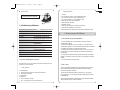
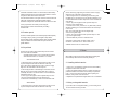
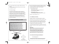
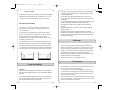
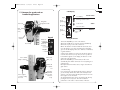
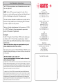
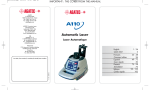
GAT220-08-2007
7/10/07
22:38
Page 2
Table of contents
1. General information
1.1 Description
1.2 Safety
1.3 Technical specifications
1.4 Laser and Keypad overview
2. How to use your CL250 laser
2.1 Horizontal set-up and operation
2.2 H.I. Alert
2.3 Rotation speed
2.4 Manual slope.
3
1. General information
GB F E D I N FIN
1.1 Description
5
The CL250 laser has these advanced features
3. Power
3.1 Installing alkaline batteries
3.2 Using rechargeable batteries
3.3 Later recharges
4. Checking and adjusting your CL250
4.1 Calibration overview
4.2 Horizontal checking and calibration
4.3 Cone error checking
7
• Automatic self-leveling in horizontal.
• Visible laser beam
• Easy electronic calibration
• Match slope in X and Y axes
1.2 Safety
8
The CL250 is a Class 3R laser, manufactured to comply with the
international rules of safety IEC 60825-1, 2001. Although the
power of the emission of the beam is less than 5mW in Class 3R,
the following cautions are recommended:
• Do not stare directly at the beam
• Do not set up the laser at eye level
5. Care and Handling
CAUTION
12
6. Warranty
13
7. Accessories
7.1 Detector
7.2 Tripods
7.3 Other accessories
Congratulations!
You have just purchased the CL250 Cone electronic level.
Although it is very simple to use, we recommend that you read this
manual before operating the laser.
13
A. CDRH warning label for USA
CLASS 3R LASER PRODUCT
WAVE LENGTH 630-680 nm
MAX. OUTPUT POWER: 5mW
LASER LIGHT: AVOID DIRECT EYE EXPOSURE
CONFORMS TO IEC 60825-1; 2001
COMPLIES WITH 21 CFR 1040.10 AND 1040.11
EXCEPT FOR DEVIATIONS
PURSUANT TO LASER NOTICE NO. 50
DATED JULY 26, 2001
AGATEC, 2202 Redmond Road
Jacksonville, AR 72076
2
3
GAT220-08-2007
7/10/07
22:38
Page 4
• Keypad overview
B. Aperture label
AVOID EXPOSURE. LASER LIGHT
IS EMITTED FROM THIS APERTURE
B
A
1.3 Technical specifications
Recommended Operating Distance
1,000 ft. (300 m) diameter
Leveling Accuracy
+/- 3/32’ at 100 ft. (+/- 7.5mm at 100 m)
Leveling Range
+/- 10%, 5.7°
Rotation Speed
0 - 90 - 600 rpm
Slope Match
Up to 10% in X and Y axes (manual mode);
also X automatic and Y manual (semi-automatic mode)
Laser Diode
635 nm; < 5mW, Class 3R
Power
2 D Size (LR20) alkaline batteries or
rechargeable batteries
Charging Time
15 hours
Battery Life
40 hours with rechargeable batteries
160 hours with alkaline batteries
Weight
3 lbs. (1.5 kg)
Size
7.75’’x 8’’x 5.5’’ (19.5 x 21 x 14 cm)
Environmental
Water and Dust resistant (IP54)
1.4 Laser and Keypad overview
See inside front cover for photos of the laser and keypad corresponding to these callouts.
• Laser overview
1. Rotatinghead
2. Aluminum head protection with axes indications
3. Laser beam aperture
4. Indexmarks
5. Batteries
6. Jack for battery charger
7. 5/8 - 11 tripod mount for horizontal set up
4
1. On/Off
2. Low battery indicator / X axis calibration LED
3. H.I. Alert Function/ Change calibration axis
4. H.I. Alert Indicator/ Y axis calibration LED
5. Manual Function/ Save calibration
6. Manual Mode Indicator
7. Rotation speed
8. Set manual slope/Move calibration beam up
9. Set manual slope/Move beam down
GB F E D I N FIN
Italics correspond to indication and keys used in calibration mode.
2. How to use your CL250 laser
2.1 Horizontal set-up and operation
1. The CL250 laser can be used directly on the ground or on a
standard 5/8-11 tripod.
2. Press the On/Off key (1) to turn the laser on. The laser does a
self-test when turned on. The beam blinks while the laser is self-leveling. After it has leveled, the head will start to rotate.
3. To select the H.I. Alert, press the H.I. key (3). The H.I. Alert function will be active 30 seconds after the CL250 has finished its
self-leveling.
4. There are two rotation speeds: 90 rpm and 600 rpm (the default
speed). To change to 90 rpm, press key (7). Press again to stop the
rotation.
5. To turn the laser off, press On/Off .
2.2 H.I. Alert
The H.I. Alert feature stops the laser automatically and sounds an
alarm if the laser is disturbed, preventing inaccurate readings.
It functions only when selected.
To activate this safeguard feature, press the H.I. key (3) after
turning the laser on. The LED (4) will blink rapidly while the laser
is self-leveling.
About 30 seconds after the head starts to rotate, the LED will blink
slowly, indicating the H.I. Alert is activated.
5
GAT220-08-2007
7/10/07
22:38
Page 6
If the laser is disturbed while in H.I. Alert mode, the head will stop
rotating, the beam will turn off, the LED indicator will be on continuously, and an alarm will sound for 30 seconds.
Turn the laser off and turn it on again. Check to see if the beam elevation has changed from its original benchmark position.
The laser is no longer in H.I. Alert mode. Press H.I. to return to H.I. Alert.
It is very important to check while you are using the
laser that it has not been moved and that your setting
is still accurate.
2.3 Rotation speed
There are 3 rotation speeds: 0, 90 and 600 rpm (the default speed).
To change to 90 rpm, press (7). Press again to stop rotation.
The laser beam is more visible at the slower speed. It’s also possible
to stop the rotation and use the beam as a point to view at a
greater distance.
2.4 Slope Match
The laser can be used to match manual slope on both X and Y
axes. Two modes are available:
• Complete manual mode: X and Y axis will be both manual
• Semi-automatic mode: X in automatic / Y in manual
(and X’ faces away). Sight along the X and X’ marks to roughly
align the X axis of the laser to the second point.
2. After turning the laser on and allowing it to self-level, press
the MAN key (5). The LED next to it (6) will blink, indicating you’re
in manual mode and can match slope in the X axis. The head will
start rotating.
3. Press ^ (8) on the keypad to match a positive slope in X
and v (9) to set a negative slope.
4. To switch to the Y axis, press the H.I. key. Both LEDs (4 and 6)
will blink, indicating you’re in manual mode and can match slope
in the Y axis.
Note: The Y axis grade will be at a 90 degree angle
from the X axis grade output.
5. Press ^ (8) on the keypad to match a positive slope in Y and
v (9) to set a negative slope.
6. Press the MAN key to return to automatic mode.
GB F E D I N FIN
CAUTION: In manual mode, the beam rotates, even if
the laser is not leveled. The H.I. Alert function is not
available when the unit is in manual mode.
3. Power
When battery power is low, the laser head will stop rotating and
the low battery LED next to the On/Off key will stay on.
• Semi-automatic mode
1. Set the laser over a start point. Turn the laser so that Y on the
top of the head protection faces the direction of the slope
(and Y’ faces away). Sight along the Y and Y’ marks to roughly
align the Y axis of the laser to the second point.
2. After turning the laser on and allowing it to self-level, hold the
MAN key (5) for a few seconds until the LED next to it (6) is lit
continually. The laser is in manual mode in Y axis and automatic
self-leveling mode in X axis.
3. Press ^ (8) on the keypad to match a positive slope in Y and
v (9) to set a negative slope; the X axis will stay level.
4. Press twice on the MAN key to return to the automatic mode.
• Manual Mode
1. Set the laser over a start point. Turn the laser so that X on the
top of the head protection faces the direction of the slope
6
3.1 Installing alkaline batteries
1. Use a coin or a screwdriver to remove the cover of the battery
compartment at the back of the laser.
2. Insert two alkaline batteries (D size or LR20), following the
polarities indicated at the bottom of the battery compartment.
(The + contact is rounded and raised). When replacing the
batteries, change both at the same time.
3. Replace the compartment and tighten with a coin or screwdriver.
3.2 Using rechargeable batteries
If your laser has a rechargeable battery, you must charge it for
15 hours before first using the laser.
7
GAT220-08-2007
7/10/07
22:38
Page 8
1. Insert the charger plug into the jack located at the back of
the laser.
2. Plug the charger into an electrical outlet (110 volts or 220 volts).
3. Charge it for 15 hours.
Check and calibrate in this order:
Check both sides of X axis.
• If X is within spec, proceed to check both sides of Y.
• If X needs calibration, calibrate X
3.3 Later recharges
The CL250 can be charged when working, if electricity is
available on the jobsite. Simply plug in the charger and keep
on working. You can also remove the battery, replace it with the
alkaline battery pack and charge the rechargeable batteries.
For optimum life of the battery, it is recommended to charge the
battery after fully discharged. To assure battery life, do not
charge over 20 hours. The battery and the charger can be
damaged if damp. Always store and charge your instrument in
a dry and covered place.
4. Checking and adjusting your CL250
THIS CHAPTER IS VERY IMPORTANT.
Here are a few simple instructions to check your
CL250 for calibration. The laser is a precision instrument and it is important that you keep it calibrated
and in proper condition. The accuracy of your work is
completely your responsibility and you should check
your instrument before beginning each job, and especially after the instrument has taken a sharp jolt or
been dropped, or when temperature changes greater
than 50 degrees F (28 degrees C) have occurred.
The laser has 2 horizontal axes: X and Y, as indicated on the top of
the laser.
X’
Y
Y’
Each end of each axis must be checked for calibration. If needed,
the axis can be calibrated, carefully following the instructions. You
can also take the laser to a service center for calibration.
GB F E D I N FIN
Check both sides of Y axis.
• If Y is within spec, proceed to final X to Y check
• If Y needs calibration, calibrate Y; proceed to X to Y check
Final X to Y check: compare X, X’, Y, Y’
4.1 Calibration overview
Calibration is electronic, using the laser keypad. The optional
detector/remote control or optional small remote may also be used.
If the beam is visible, calibrate using the non-rotating point. If it’s
too bright to see the beam, you’ll use the detector and will need to
have the beam rotating. When you’re in calibration mode, press
the rotation key (7) on the laser to rotate the beam.
The axis LED should blink slowly when in calibration mode. When
the laser is self-leveling or making an adjustment, the LED will blink
rapidly.
IMPORTANT:
When pressing an arrow key to move the beam for calibration, use short, rapid clicks. Do not hold the key
down. One click will move the beam a very small
amount (1/32" at 150' or 1mm at 100m). After pressing
the key, the LED will blink rapidly as the laser reacts.
Wait until the LED returns to a slow blink to proceed.
X
4.2 Horizontal checking and calibration
4.2.1 Checking X axis
1. Place the laser on a flat surface or tripod 100 ft. (30 m) away from
a wall. Position so that X’ (noted on top of laser) is facing the wall.
8
9
GAT220-08-2007
7/10/07
22:38
Page 10
2. Turn on the laser.
3. Mark the location of the center of the beam. If it’s too bright to
see the beam, use the detector.
4. Rotate the laser 180 degrees so that X faces the wall.
5. Mark the location of the center of the beam near the first mark
so that both marks are in line, one above the other.
6. At 100 ft., the marks should be no more than 3/16" apart
(at 30m, no more than 5mm apart). This is within the stated
accuracy of ±3/32" at 100 ft. (± 0.0075%).
7. If the marks are close enough, X axis is within calibration. The
second axis Y must then be checked (see later section).
If the marks are not close enough, the X axis needs to be calibrated.
4.2.2 Calibrating X axis
The laser must be calibrated to bring the beam to the center of the
two X marks. Read "Calibration Overview" before proceeding.
1. Turn off the laser.
2. Hold the MAN (5) key. While holding, momentarily press the
ON key.
3. After the LEDs blink in sequence, release the MAN (5) key.
4. X LED will blink rapidly, indicating leveling. When the LED
blinks slowly, the laser is ready to calibrate.
5. If you have not moved the laser, use the X marks made in
previous steps of “Checking X axis”.
6. Use arrows on the keypad to move beam up or down to the
halfway mark. If the X axis is toward the wall with the marks, use
the ^ key (8) to raise beam, and the v key (9) to lower beam.
7. After completing the X calibration, press the H.I. key (3) to
change the axis and to calibrate the Y axis. (On the remote, press
the double arrow key >>l)
8. If the Y axis doesn’t have to be calibrated, press MAN key (5)
to save the calibration you’ve just made on X axis. (On remote, use
key with the small dot.)
If you are not sure of the calibration, don’t save it and turn the
laser off using the On/Off key.
10
4.2.3 Checking Y axis
1. Rotate the laser 90 degrees so that Y’ is facing the wall.
2. Mark the location of the center of the beam.
3. Rotate the laser 180 degrees so that Y faces the wall.
4. Mark the location of the beam center near the first mark.
5. At 100 ft., the marks should be no more than 3/16" apart
(at 30m, no more than 5 mm apart). This is within the stated
accuracy of ±3/32” at 100 ft. (± 0.0075%).
6. If the marks are close enough, Y axis is within calibration.
Proceed to “Final X to Y Check.” If the marks are not close enough,
Y axis needs to be calibrated.
GB F E D I N FIN
4.2.4 Calibrating Y axis
The laser must be calibrated to bring the beam to the center of the
two Y marks. Read "Calibration Overview" before proceeding.
If you are still in calibration mode from the X axis, turn Y towards
the wall and press the H.I. key to change to the Y axis. When the Y
LED blinks slowly, it’s ready to be calibrated in Y axis.
If you’re no longer in calibration mode
1. Turn off the laser.
2. Hold the MAN (5) key. While holding, momentarily press the ON key.
3. After the LEDs blink in sequence, release the MAN (5) key.
4. Select the Y axis by pressing the HI key on the laser keypad
(on the remote, press the double arrow key >>l ).
5. Y LED will blink rapidly, indicating leveling. When the LED blinks
slowly, the laser is ready to calibrate.
6. If you have not moved the laser, use the Y marks made in previous
steps of “Checking Y axis”.
7. Use arrows on the keypad to move beam up or down to the
halfway mark. If the Y axis is toward the wall with the marks,
use the ^ key (8) to raise beam, and the v key (9) to lower beam.
8. Press MAN key (5) to save the calibration you’ve just made on Y
axis. (On remote, use key with the small dot).
If you are not sure of the calibration, don’t save it and turn the laser
off using the On/Off key.
11
GAT220-08-2007
7/10/07
22:38
Page 12
Final X to Y Check
As a final check, compare X and Y axes to be sure that your adjusted
calibration is within the specs of ±3/32. The marks for X, X’, Y, and
Y’ should be no more than 3/16" apart at 100 ft. (5 mm at 30 m).
4.3 Cone error checking
1. Set up your CL250 2 ft. or 1 meter from a wall (a) or a
pole and 100 ft. or 30 meters from another wall or pole (b).
2. Turn the laser on.
3. When the laser is leveled, stop the rotation and mark the
location of the beam (center of the beam) on the near wall (a),
using the detector if ambient conditions are too bright.
4. Rotate the laser 180° and mark the location of the center of
the beam on the far wall (b).
5. Install the laser 2 ft. or 1 meter from the far wall. When the
CL250 has self-leveled, line up the beam on the previous mark (b).
6. Mark the location of the beam on the wall near the first mark (a).
7. Compare the two measurements. If the difference between aa’bb’ is more than 3/16" or 5mm, contact your local service center.
5. Care and Handling
CAUTION
The use of controls or adjustments or performance of procedures
other than those specified herein may result in hazardous radiation
exposure.
The CL250 is a precision instrument, which must be handled with
care. Avoid shock and vibrations. Always store and transport the
laser and its accessories in the carrying case.
12
Although your CL250 is weather resistant, you must always keep
your laser and its accessories dry and clean after using. This will
increase the battery life.
Do not store your laser at temperatures below -4°F (-20°C) or
above 176°F (80°C) because some electronic components could
be damaged.
Do not store your instrument in its case if the instrument or the case
is wet, to avoid water condensation inside the instrument.
To maintain the precision of your CL250, check it and adjust it
regularly.
Keep the aperture lens dry and clean. Use a soft cloth and glass
cleaner to clean it.
We recommend to regularly charge the batteries of the CL250.
Nevertheless, make sure to charge them only when they are out of
power or becoming so. Recharging batteries that are still useable
will shorten their capacity.
GB F E D I N FIN
6. Warranty
The CL250 laser is guaranteed to be free of manufacturing
defects for a period of Two years. Any abnormal usage or if the
instrument has been subjected to shock will void this warranty.
Under no circumstances will be the liability of the manufacturer
exceed the cost of repairing or replacing the instrument.
Disassembling the instrument by other than qualified and certified technicians will void this warranty.
Specifications subject to change without notice.
7. Accessories
Detectors are recommended when it is difficult to see the laser
beam, such as outdoors or in bright light.
If you cannot pick up the beam with the detector, check how
you are lined up with the laser. One of the head protection supports on the laser may be blocking the beam; move to the left
or right to receive the beam.
The head protection may be removed from the laser by pivoting
the two security locks. This will not affect the performance or the
water or dust resistance of the laser.
13
GAT220-08-2007
7/10/07
22:38
Page 14
• LCD Display
7.1 Detector for grade rods or
handheld applications
High
Near
grade high
On-grade
alignment notch
Level vial
Low battery
LCD
screen
Near
grade low
(front)
STATUS
Blinking: Normal volume
Solid: Loud
On-grade
BATTERY
SOUND
GB F E D I N FIN
No horn: Mute
Standard
Fine
ACCURACY
( Default
mode )
Low
Keypad
Detection
window
• Using the detector
Choice of
sound level
Rod clamp
Choice of
accuracy
On/Off
Turn to attach
clamp to detector
LCD screen
(rear)
Bubble vial
to plumb
rod
9V battery
compartment
Turn to tighten
or remove clamp
from rod
14
(follow polarity
indications
inside)
1. Press the On/Off key to turn on the detector.
2. Press the middle key to select the accuracy (deadband).
3. Press the top key to select the sound level.
4. Turn the detection window towards the laser beam, and
move the detector up or down according to the information
given on the LCD display. There are 5 channels of information,
or grade indicators.
A down arrow indicates you must move the detector down to
reach the laser reference; an up arrow, move it up. When a
horizontal line appears on the display, the detector is at the
same level as the laser beam.
5. Press the On/Off key to turn the detector off. It will
automatically shut off after 10 minutes if not used (and give a
warning beep).
6. Keep the detection window clean, using a soft cloth and
glass cleaner.
* Troubleshooting
If you cannot pick up the beam with the detector, check how
you are lined up with the laser. One of the head protection
supports on the laser may be blocking the beam; move to the
left or right to receive the beam.
The metal head protection can be removed from the laser by
pivoting the two security locks. This will not affect the
performance or the water or dust resistance of the laser.
15