1
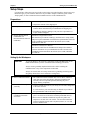
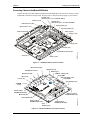
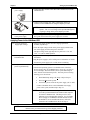
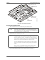
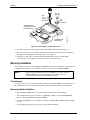
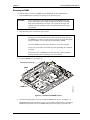
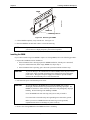
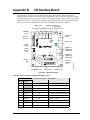
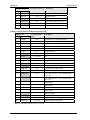
LittleBoard™ 550 Single Board Computer QuickStart Guide P/N 5001741A Revision A Notice Page NOTICE No part of this document may be reproduced, transmitted, transcribed, stored in a retrieval system, or translated into any language or computer language, in any form or by any means, electronic, mechanical, magnetic, optical, chemical, manual, or otherwise, without the prior written permission of Ampro Computers, Incorporated. DISCLAIMER Ampro Computers, Incorporated makes no representations or warranties with respect to the contents of this manual or of the associated Ampro products, and specifically disclaims any implied warranties of merchantability or fitness for any particular purpose. Ampro shall under no circumstances be liable for incidental or consequential damages or related expenses resulting from the use of this product, even if it has been notified of the possibility of such damages. Ampro reserves the right to revise this publication from time to time without obligation to notify any person of such revisions. If errors are found, please contact Ampro at the address listed below on the Notice page of this document. TRADEMARKS Ampro and the Ampro logo are registered trademarks, and CoreModule, EnCore, Little Board, LittleBoard, MightyBoard, MiniModule, ReadyBoard, ReadyBox, and ReadySystem are trademarks of Ampro Computers, Inc. All other marks are the property of their respective companies. REVISION HISTORY Revision Reason for Change Date A Initial Release Jan/05 Ampro Computers, Incorporated 5215 Hellyer Avenue San Jose, CA 95138-1007 Tel. 408 360-0200 Fax 408 360-0222 www.ampro.com © Copyright 2005, Ampro Computers, Incorporated Audience Assumptions This guide is for the person who designs computer related equipment, including but not limited to hardware and software design and implementation of the same. Ampro Computers, Inc. assumes you are qualified in designing and implementing your hardware designs and its related software into your prototype computer equipment. ii QuickStart Guide LittleBoard 550 Contents Chapter 1 Setting Up the LittleBoard 550......................................................................................1 Using the LittleBoard 550 QuickStart Kit ............................................................................................1 Requirements .................................................................................................................................1 What’s in the Box ...........................................................................................................................1 Setup Steps ........................................................................................................................................2 Preparations ...................................................................................................................................2 Setting Up the Workspace..............................................................................................................2 Connecting Cables to LittleBoard 550 Module...............................................................................3 Connecting Peripherals and Boot Devices.....................................................................................7 Applying Power to the LittleBoard 550 ...........................................................................................8 Chapter 2 Installing LittleBoard 550 Options..............................................................................11 CompactFlash Installation ................................................................................................................11 Tools Required .............................................................................................................................11 CompactFlash Card Installation Guidelines .................................................................................11 Installing the CompactFlash Card ................................................................................................11 Removing the CompactFlash Card ..............................................................................................13 Memory Installation ..........................................................................................................................14 Tools Required .............................................................................................................................14 Memory Installation Guidelines ....................................................................................................14 Removing the DIMM.....................................................................................................................15 Installing the DIMM.......................................................................................................................16 Installing Software, Drivers, and Utilities ..........................................................................................18 Appendix A Technical Support........................................................................................................21 Appendix B I/O Interface Board .......................................................................................................23 Appendix C Connector Part Numbers.............................................................................................27 NOTE List of Figures Figure 1-1. Figure 1-2. Figure 1-3. Figure 1-4. Figure 1-5. Figure 1-6. Figure 1-7. Figure 2-1. Figure 2-2. Figure 2-3. Figure 2-4. Figure 2-5. LittleBoard 550 The graphic illustrations found in this manual are intended as aids in identifying the connector locations and components on the board. You may find slight variations between your board and the boards shown in this manual to due board revisions. Refer to Figure 1-5 and the LittleBoard 550 Reference Manual for the most current board revision and the connector pin/signal tables for specific information. LittleBoard 550 Connector Locations..............................................................................3 I/O Board Connector Locations.......................................................................................3 Connecting LittleBoard 550 Utility, Audio, Parallel, and Serial Cables...........................4 Connecting I/O Board Audio and Utility Cables ..............................................................4 LittleBoard 550 Connectors ............................................................................................5 Connecting LittleBoard 550 Video, IDE, Floppy, and Ethernet Cables ..........................6 Connecting Peripherals to I/O Board ..............................................................................7 Installing the CompactFlash Card.................................................................................12 CompactFlash Card Installed........................................................................................13 Removing the CompactFlash Card...............................................................................14 LittleBoard 550 DIMM Location.....................................................................................15 Removing a DIMM from a Slot......................................................................................16 QuickStart Guide iii Contents Figure 2-6. Installing a DIMM into a Slot......................................................................................... 17 Figure B-1. I/O Interface Board ....................................................................................................... 23 List of Tables Table 1-1. Jumper Settings ............................................................................................................. 10 Table A-1. USA Technical Support Contact Information ................................................................ 21 Table B-1. Utility 1 Interface Pin/Signal Descriptions (J10) ............................................................ 23 Table B-2. Utility 2 Interface Pin/Signal Descriptions (J8) .............................................................. 24 Table B-3. Utility 3 Interface Pin/Signal Descriptions (J9) .............................................................. 25 Table C-1. Connector and Manufacturers' Part Numbers............................................................... 27 iv QuickStart Guide LittleBoard 550 Chapter 1 Setting Up the LittleBoard 550 Using the LittleBoard 550 QuickStart Kit This guide provides the most efficient way to set up your LittleBoard™ 550 single board computer (SBC). The instructions provided in this guide include: • Removing the LittleBoard 550 from the shipping container and inventorying the accessories • Connecting cables to the LittleBoard 550 and I/O Interface board • Connecting the peripherals, boot devices, and power supply to the LittleBoard 550 • Powering up the LittleBoard 550 Information not provided in this QuickStart Guide includes: • LittleBoard 550 Specifications • Environmental requirements • LittleBoard 550 connector/pin numbers and definitions • Supplied software use and programming considerations Requirements The following peripherals and devices are needed to make full use of the LittleBoard 550. • Peripherals: (Customer Provided) ♦ PS/2 Keyboard ♦ PS/2 Mouse ♦ CRT Monitor • Power Supply: (Customer Provided) ♦ AT, ATX, or Lab power supply – One of these power supplies is required to provide power to the LittleBoard 550, the I/O Interface board, and the externally connected I/O peripheral devices. An AT/ATX power connector adapter is provided by Ampro. • Choice of Boot Device: (Customer Provided) ♦ Floppy Disk drive ♦ IDE hard disk drive (See preinstalled OS Note in text) ♦ CompactFlash card (See preinstalled OS Note in text) ♦ CD-ROM • Optional Devices/Connections: (Customer Provided) ♦ TFT or LVDS Flat Panel ♦ Ethernet (or LAN Boot option - Refer to LittleBoard 550 Reference Manual) ♦ USB ♦ Audio components, such as headphones or speakers, and microphones What’s in the Box Refer to the QuickStart Kit Contents Sheet for a list of the cables, documents, and other items in the shipping container. LittleBoard 550 QuickStart Guide 1 Chapter 1 Setting Up the LittleBoard 550 Setup Steps It is important to follow the setup steps in this section in the exact order listed here, but skip any steps that do not apply to your situation. References are provided to chapters within this guide or other Ampro guides, for more information about installation and use of this LittleBoard 550. Preparations 1) Open shipping box • Locate the QuickStart Kit Contents Sheet • Unpack the contents of the shipping box 2) Verify Contents • Verify the contents of the shipping box against the QuickStart Contents Sheet included with your LittleBoard 550 shipping box. • If anything is missing or damaged, call your sales representative or Ampro Technical Support. 3) Support Documentation (LittleBoard 550 Documentation & Software CD-ROM) LittleBoard 550 QuickStart Guide This document, provided as a hardcopy, describes how to setup, install, and power up the LittleBoard 550 found in the QuickStart Kit and is also on the LittleBoard 550 Documentation & Software (Doc & SW) CD-ROM as a PDF file. LittleBoard 550 Reference Manual This document describes the LittleBoard 550 and provides detailed reference information for your LittleBoard 550 and is located on the LittleBoard 550 Documentation & Software (Doc & SW) CD-ROM as a PDF file. Setting Up the Workspace CAUTION To prevent damage to the electronic components on the LittleBoard 550, do not handle the board until you have used Electrostatic Discharge precautions. Always touch a grounded, unpainted metal surface before touching the LittleBoard 550 or any of the components on the board. Always use an anti-static wrist strap connected to a grounding mat having staticdissipating characteristics and is attached to earth ground. 4) Select workbench location • The workbench location should be flat, clear of debris, and have a static-free mat (or the equivalent) to place the LittleBoard 550 assembly onto for setup and operation (including the power supply and any peripherals). 5) Connect an ESD strap to your body • Connect an ESD strap between your body (wrist or ankle) and ground or the static-free mat. 6) Unpack the LittleBoard 550 and its accessories. 2 If you do not have your own ESD strap, an ESD kit is provided in the QuickStart Kit with an anti-static wrist strap. • Remove the LittleBoard 550 from its protective plastic case and place it on static-free work surface with the preinstalled memory. • Remove the I/O Interface board from its protective plastic case and place it on static-free work surface. The external connections on the I/O Interface board, such as keyboard, mouse, etc. are used for the LittleBoard 550. QuickStart Guide LittleBoard 550 Chapter 1 Setting Up the LittleBoard 550 Connecting Cables to LittleBoard 550 Module Connect the cables provided with the LittleBoard 550 QuickStart Kit to the respective connectors on the LittleBoard 550 and I/O board provided. Skip any steps or cable(s) that do not apply to your situation. Serial A (J11) (Serial Ports 1 & 2, or COM 1 & COM 2) Power In (J10) Serial B (J13) (Serial Ports 3 & 4, or COM 3 & COM 4) Ethernet Port 2 (J32) Primary IDE (J12) Ethernet Port 1 (J7) Secondary IDE (J17) Utility 2 (J24) Audio In/Out (J28) Utility 1 (J16) Floppy (J14) Parallel (J15) CRT (J5) LB550QSG_03a CompactFlash Socket (J23 Utility 3 (J18) Figure 1-1. LittleBoard 550 Connector Locations IR Transceiver (U1) Keyboard (J15) Headphone Out (J7) Mouse (J1) USB 0 & 1 Stack (J14) (Top USB0) Speaker Out (J6) Mic In (J4) USB 2 & 3 Stack (J13) (Top USB2) Line In (J3) Aux Voltages (J11) CD-ROM In (J2) Audio (J16) to LittleBoard 550 (J28) Utility 1 (J10) to LittleBoard 550 (J16) Mono Out (J5) Utility 3 (J9) to LittleBoard 550 (J18) Aux Battery (J12) Utility 2 (J8) to LittleBoard 550 (J24) LB550QSG_07a Reset Switch (S1) Figure 1-2. I/O Interface Board Connector Locations LittleBoard 550 QuickStart Guide 3 Chapter 1 Setting Up the LittleBoard 550 1) Connect Utility 1 Cable Connect the Utility 1 cable between the LittleBoard 550's Utility 1 (J16) and Utility 1 (J10) on the I/0 Interface board. See Figures 1-1, 1-2, and 1-3. 2) Connect Utility 2 Cable Connect the Utility 2 cable between Utility 2 (J24) on the LittleBoard 550 and Utility 2 (J8) on the I/0 Interface board. See Figures 1-1, 1-2, and 1-3. 3) Connect Utility 3 Cable Connect the Utility 3 cable between Utility 3 (J18) on the LittleBoard 550 and Utility 3 (J9) on the I/0 Interface board. See Figures 1-1, 1-2, and 1-3. 4) Connect Audio In/Out Cable Connect the Audio cable between the Audio In/Out (J28) on the LittleBoard 550 and the Audio In/Out (J16) on the I/0 Interface board. See Figures 1-1, 1-2, and 1-3. Serial Port 1 Serial A Interface (J11) Serial Port 3 Serial Port 2 Serial Port 4 Audio In/Out (J28) to I/O Interface Board (J16) Parallel (J15) Utility 2 (J24) to I/O Interface Board (J8) LB550QSG_03b Utility 1 (J16) to I/O Interface Board (J10) Serial B Interface (J13) Utility 3 (J18) to I/O Interface Board (J9) Figure 1-3. Connecting LittleBoard 550 Utility, Audio, Parallel, and Serial Cables From LittleBoard 550 (J16) to Utility 1 (J10) From LittleBoard 550 (J28) to Audio In/Out (J16) From LittleBoard 550 (J24) to Utility 2 (J8) From LittleBoard 550 (J18) to Utility 3 (J9) LB550QSG_07b Figure 1-4. Connecting I/O Board Audio and Utility Cables NOTE 4 Ensure you match the red strip on the ribbon cables (pin-1) between the I/O Interface board pin-1’s and the pin-1’s on the LittleBoard 550 shown in Figures 1-4, 1-5, and B-1. QuickStart Guide LittleBoard 550 Chapter 1 Setting Up the LittleBoard 550 L9 LCD 2 (J4) LCD 1 (J3) CRT Fuse (F5) J5 LB550QSG_01e CRT (J5) J3 L8 F5 J4 Fan (J2) DIMM1 J2 CPU (U1) DIMM1 L2 ge id br th 2) or U N ( L3 LVDS (J31) J18 U34 Utility 3 (J18) L5 J31 U10 Et h (U e rn 5) e t U21 ge r id hb ) ut U3 So ( U15 J1 PC/104-Plus (J21) U27 J21 Audio In/ Out (J28) U26 E th e (U rn e 6) t U25 CompactFlash Socket (J23) U22 COM2 RS485 Term (JP6) Y1 U4 U24 COM1 RS485 Term (JP5) J28 Y5 U33 COM4 RS485 Term (JP8) J23 U16 COM3 RS485 Term (JP7) U23 U11 CF Voltage Select (JP3) U20 U17 JP6 BAT1 U19 JP5 CF Master/ Slave (JP4) Ethernet Port 2 (J32) U9 JP4 JP3 JP8 JP7 Parallel (J15) J11 J13 J15 U14 Floppy (J14) U12 U8 J7 J32 Ethernet Port 1 (J7) U7 J14 J17 Utility 2 (J24) J24 J16 Utility 1 (J16) J10 J12 Primary IDE (J12) Secondary IDE (J17) Serial B (J13, Serial Ports 3 & 4) Power In (J10) Serial A (J11, Serial Ports 1 & 2) Ethernet Grounding Pad Board Grounding Pad (8) Figure 1-5. LittleBoard 550 Connectors CAUTION The two Ethernet ports share a common ground (transformer center tap), that is floating until you determine how the ground is connected. The grounding holes (8) of the LittleBoard 550 are at the ground potential (return) provided by the AT power supply. You must decide how to best ground the Ethernet ground plane for proper operation in your situation. NOTE To conform to the PC/104 and PC/104-Plus standards, keys have been inserted into specific pins in the PC/104 and PC/104-Plus connectors. Refer to the LittleBoard 550 Reference Manual for more information. LittleBoard 550 QuickStart Guide 5 Chapter 1 Setting Up the LittleBoard 550 Skip any of the following steps that do not apply to your situation. 5) Connect Serial 1 Interface cables Connect the Serial 1 interface cable for COM 1 and COM 2 to Serial 1 Interface connector (J11) on the LittleBoard 550. See Figures 1-1 to 1-5. 6) Connect Serial 2 interface cables Connect the Serial 2 interface cable for COM 3 and COM 4 to the Serial 2 Interface connector (J13) on the LittleBoard 550. See Figures 1-1 to 1-5. 7) Connector Parallel cable Connect the Parallel cable to the Parallel connector (J11) on the LittleBoard 550. See Figures 1-1 to 1-6. 8) Connect Floppy Cable Connect the floppy cable to the floppy drive connector (J14). See Figures 1-1, 1-5, and 1-6. 9) Connect Primary IDE Cable Connect an IDE cable to the Primary IDE connector (J12) on the LittleBoard 550. See Figures 1-1, 1-2, and 1-3. 10) Connect Secondary IDE Cable Connect an IDE cable to the Secondary IDE connector (J17) on the LittleBoard 550. See Figures 1-1, 1-2, and 1-3. 11) Connect Video cable (CRT) Connect the Video cable to the CRT connector (J5) on the LittleBoard 550. See Figures 1-1, 1-2, and 1-3. 12) Connect an Ethernet Port Connect an Ethernet cable to the one of the Ethernet ports. Primary IDE (J12) Secondary IDE (J17) Ethernet Port 2 (J32) (This port is optional on 300MHz model.) Power In (J10) Floppy Drive (J14) LB550QSG_03c Ethernet Port 1 (J7) CRT (J5) Figure 1-6. Connecting LittleBoard 550 Video, IDE, Floppy, and Ethernet Cables 13) Verify the Jumper Settings • Check the jumper settings before applying power, since one of the jumpers may have fallen off in transit. • Refer to Figure 1-4 for the jumper locations and Table 1-1, located at the end of this chapter for the default jumper settings. 6 QuickStart Guide LittleBoard 550 Chapter 1 Setting Up the LittleBoard 550 Connecting Peripherals and Boot Devices 14) Connect the I/O devices • Connect the keyboard to the I/O board connector J1A. • If your are using a USB keyboard, connect it to the USB 0 connector (lower USB on J14) on the I/O board. • Connect the mouse cable to the I/O board connector J1B. • If your are using a USB mouse, connect it to the USB 1 connector (upper USB on J14) on the I/O board. IR Transceiver (U1) Headphone Out (J7) Keyboard (J15) Mouse (J1) Speaker Out (J6) USB 0 & 1 Stack (J14) (Top USB0) USB 2 & 3 Stack (J13) (Top USB2) Mic In (J4) Line In (J3) CD-ROM In (J2) Aux Voltages (J11) Reset Switch (S1) Aux Battery (J12) PC Speaker (LS1) LB550QSG_07c Mono Out (J5) Figure 1-7. Connecting Peripherals to I/O Board 15) Connect boot devices • Use one of the four options listed here to connect a boot device (OS) to the LittleBoard 550: a. Connect a floppy disk drive to the floppy disk drive cable connected to J14 on the LittleBoard 550. Or Connect a USB floppy drive to one of the USB ports, Or b. Connect an IDE hard disk drive to a free connector on the one of the IDE cables, Primary (J12) or Secondary (J17), on the LittleBoard 550. • Ampro recommends not using a preinstalled OS on a hard disk drive to boot and load the operating system. See Note with step 20. Or Connect a USB hard drive to one of the USB ports, Or c. Connect a CD-ROM drive to an available connector on one of the IDE cables, Primary (J12) or Secondary (J17), on the LittleBoard 550. Or Connect a USB CD-ROM to one of the USB ports, Or d. Install a CompactFlash (CF) card with a bootable OS into the CompactFlash socket (J23). CompactFlash Card LittleBoard 550 Instructions for installing the CompactFlash card into the socket (J23) on the LittleBoard 550, are provided later in this manual in Chapter 2, Installing LittleBoard 550 Options. • Ampro recommends not using a preinstalled OS on a CompactFlash card to boot and load the operating system. See Note with step 20. QuickStart Guide 7 Chapter 1 Setting Up the LittleBoard 550 16) Connect the monitor and power supply • Connect the CRT monitor to the video cable connected to J5 on the LittleBoard 550. • Connect a power supply (AT, ATX, or lab supply) to the J10 connector on the LittleBoard 550 using the adapter provided. NOTE 17) Connect all support devices to the power supply The LittleBoard 550 only requires +5 volts externally to operate. The +3.3 bus voltage can be provided through J10, requiring a change in the power adapter provided. • Ensure all support devices you have plugged into the LittleBoard 550 have good connections to the power supply (AT or ATX). Applying Power to the LittleBoard 550 18) Check/Set the Power Supply Input Voltage • If the power supply module uses auto-ranging operation at 50/60Hz, skip this step. • Check the input voltage switch on the power supply located on the rear of the supply just below the power connector. The input voltage switch typically has two positions: 115 or 230 volts – 115 volts is default position. • Plug the CRT monitor’s power cord into an AC outlet and turn on the monitor. 19) Power up the LittleBoard 550 • Plug the power supply’s (AT or ATX) power cord into the AC outlet. • Turn On the power supply (AT or ATX) before continuing. 20) Verify the LittleBoard 550 powers-up satisfactorily • Verify the LittleBoard 550 passes POST successfully. • If the desired operating system is not loaded on one of the boot devices (floppy drive or CD-ROM) prior to power up, you will see an error message “Disk boot failure, insert system disk and press enter” near the end of the boot process. The boot process will stop, allowing you to select from: ♦ Enter BIOS Setup using S for Setup or skip to Step 21. ♦ Press R to Reboot the system ♦ Turn off the power switch on the power supply (AT or ATX). Connect a bootable device to the LittleBoard 550, reapply power to the system, and then skip to Step 21. NOTE NOTE 8 Ampro does not recommend using a hard disk drive or CF card with a preinstalled OS from another model computer to boot the LittleBoard 550. This has proven to cause problems or provide unreliable operation. Use a bootable device (floppy or CD-ROM) to load the desired OS onto the hard drive (or CF) and then the drivers, while still attached to the LittleBoard 550. Refer to Step 23. For the most current BIOS Information, refer to the Hardware Release Notes provided as hard copy in the shipping container. QuickStart Guide LittleBoard 550 Chapter 1 Setting Up the LittleBoard 550 21) Enter BIOS Setup • Press the <Del> key during POST, to enter BIOS Setup. • Use BIOS Setup during the initial boot to set the desired options (time and date, alter the boot order of the floppy drive, CD-ROM, or hard disk drive, etc.). • Refer to the next step to alter the boot sequence, while in Setup. • If you need to alter the boot sequence to select a bootable device, perform the items listed in this step. a) Select the BIOS and Hardware Settings menu as shown in the figure to the right and press Enter. > BIOS and Hardware Settings < Reload Initial Settings Load Factory Default Settings Exit, Saving Changes Exit, Discarding Changes b) Select the first drive in the Boot Order as highlighted to the right. This example assumes Drive A is a 3 ½” floppy drive, Drive C is an IDE HDD, and Drive D is an IDE CD-ROM. NOTE c) The CD-ROM or CompactFlash (CF) must be listed in Drive Assignment and the Boot Order to be recognized by the BIOS. Use the Arrow keys and PU/PD keys to change the CD-ROM into the First Boot Device in the boot order. d) Exit and Save changes. Ampro Setup Utility for LittleBoa [Drive Assignment] Drive A 1.44 MB, 3.5” Drive B (none) Drive C HDD/CF on Pri Master Drive D CDROM on Pri Slave (none) Drive E Drive F (none) Drive G (none) [Boot Order] > Boot 1st Drive A: < Boot 2nd Drive C: Boot 3rd CDROM (none) Boot 4th (none) Boot 5th LB550BtSeqa The sub-steps listed here show you how to change the Boot Sequence while in the BIOS Setup Utility. Ampro Setup Util enterBIOSb 22) Alter Boot Order, only if needed • Use the PU/PD keys to change from Drive A: (Floppy) to [CDROM] in the boot order. • You will need to change Drive A:(Floppy) to the Third Boot Device or another boot device, to keep it in the boot sequence without a break in the boot device order. • Check the other BIOS settings, related to the floppy drive before exiting BIOS setup. The other settings in BIOS Setup that also affect the floppy drive during the boot sequence, or normal operation are: Floppy Seek, Floppy Swap, and Floppy (On-Board Controllers). These fields may need to be checked or changed too! LittleBoard 550 QuickStart Guide 9 Chapter 1 Setting Up the LittleBoard 550 23) Install the desired Operating System (OS) • Locate the desired Operating System (OS) diskette(s) or CD-ROM and follow the manufacturer’s instructions for installing the OS and the necessary drivers. ♦ For Windows Operating Systems, some of the necessary drivers may be found on the manufacturer’s installation CD-ROM. For other Operating Systems, some or all of the necessary drivers may be found on the manufacturer’s diskette(s) or CD-ROM. • If you require drivers that are not available on the OS manufacturer’s diskette(s) or CD-ROM, refer to Installing Software, Drivers, and Utilities in Chapter 2 of this manual and the LittleBoard 550 software directory on the LittleBoard 550 Doc & SW CD-ROM for instructions. ♦ NOTE NOTE As an alternate, Contact Ampro to request a pre-installed OS on a CompactFlash card specifically configured for your system. The LittleBoard 550’s shipped from the factory are initially configured for CRT support. Ampro provides LCD/TFT support for flat panels with specific resolutions. If you have questions about the flat panels, contact Technical Support through Virtual Technician for help in setting up the flat panel configurations. Refer also to the LittleBoard 550 Reference Manual and the Release Notes for additional instructions and information when customizing the BIOS to a particular flat panel. Table 1-1. Jumper Settings 10 Jumper # Installed Removed/Installed JP3 – CompactFlash Voltage Selection Enable +5V (1-2) (Default) Enable +3.3V (1-3) JP4 – CompactFlash Master/Slave Enable Master (pins 1-2) Enable Slave (Removed) (Default) JP5 – Serial Port 1 (COM1) RS485 Termination Enable Termination (1-2) Disable Termination (Removed) (Default) JP6 – Serial Port 2 (COM2) RS485 Termination Enable Termination (1-2) Disable Termination (Removed) (Default) JP7 – Serial Port 3 (COM3) RS485 Termination Enable Termination (1-2) Disable Termination (Removed) (Default) JP8 – Serial Port 4 (COM4) RS485 Termination Enable Termination (1-2) Disable Termination (Removed) (Default) QuickStart Guide LittleBoard 550 Chapter 2 Installing LittleBoard 550 Options The procedures in the first part of this chapter describe how to install or remove the LittleBoard™ 550 SBC (Single Board Computer) options onto or from the board, including the CompactFlash card and DIMMs. Brief instructions for accessing and using the LittleBoard 550 Doc & SW (Documentation and Software) CD-ROM and a brief description for loading supported Operating Systems is also provided at the end of this chapter. CompactFlash Installation The CompactFlash interface allows you to substitute solid-state flash memory cards for a conventional hard disk drive. Any of the supported operating system, utilities, drivers, and application programs can easily be run from the CompactFlash card without modification. You may use Type I or Type II CompactFlash cards from commercially available suppliers. NOTE Tools Required The following tools are needed to remove and install the CompactFlash card onto or off of the LittleBoard 550 SBC. • Small to medium flat blade screwdriver • Anti-static service kit - Use a complete anti-static service kit (or the equivalent) to remove or install the CompactFlash card. A complete anti-static service kit should include a staticdissipating work surface, a chassis clip lead, and a wrist or ankle strap. CompactFlash Card Installation Guidelines The CompactFlash card, when installed, becomes one of the IDE drives supported by the EIDE disk controller on the LittleBoard 550 SBC. • Configure it as an IDE hard drive in the “Drive Assignment Order” and “Boot Order” as a hard disk drive in the BIOS Setup. • The CompactFlash Card becomes the master or slave depending on the setting of the Master/Slave jumper (JP4). • The voltage selection jumper (JP3) for the CompactFlash Card should be set before applying power to the LittleBoard 550. • No two devices on the IDE bus can both be master or both be slave at the same time. Installing the CompactFlash Card 1. LittleBoard 550 preparation: ♦ If the LittleBoard 550 is already prepared for CompactFlash installation, with power disconnected, skip to Step 3. ♦ If the LittleBoard 550 is connected and operating, power down the system and continue with next step. CAUTION LittleBoard 550 To prevent damage to the LittleBoard 550, ensure the power supply is turned off and the power cord has been removed from the power source. The typical AT power supply will continue to provide standby current to the chassis until the power cord is disconnected. QuickStart Guide 11 Chapter 2 Installing LittleBoard 550 Options 2. Disconnect the power cord from the power source. CAUTION To prevent damage to the LittleBoard 550 or the CompactFlash card, do not touch either one until you have discharged yourself and have followed good Electrostatic Discharge principals. The LittleBoard 550 and the CompactFlash card are sensitive to static electricity and can be easily damaged by improper handling. Do the following when handling either one: Leave the CompactFlash in the anti-static bag until you are ready to install it. Always use an anti-static wrist/ankle strap and a grounding mat connected to ground. Before you remove a CompactFlash from the anti-static bag, touch a grounded, unpainted metal surface to discharge any static electricity. 3. Check for bent pins or debris on the pins of the CompactFlash socket (J23). 4. Remove the CompactFlash card from its protective bag, handling the CompactFlash card by its edges. 5. Insert the CompactFlash card into the slot provided by the tabs on the protective cover as shown in Figure 2-1. The CompactFlash card edge and socket are keyed to install in only one orientation. Protective cover (Do not remove) CompactFlash Socket (J23) LB550QSG_04a Pin-1 Maker Insert CompactFlash Card Figure 2-1. Installing the CompactFlash Card 6. Push the CompactFlash card into the socket until it is firmly into the socket and mates with the pins. See Figures 2-1 and 2-2. 7. Ensure all the connections to the LittleBoard 550 are still connected. 8. Plug the power supply’s power cord into the AC power source and restore power. 12 QuickStart Guide LittleBoard 550 Chapter 2 Installing LittleBoard 550 Options CompacFlash Socket (J23) CompactFlash Card LittleBoard 550 LB550QSG_03d Protective Cover (Do not remove) Figure 2-2. CompactFlash Card Installed Removing the CompactFlash Card 1. If the LittleBoard 550 SBC is already powered up, power down the system. CAUTION To prevent damage to the LittleBoard 550 or the CompactFlash, ensure the power supply is turned off and the power cord has been removed from the power source. The typical AT power supply will continue to provide standby current to the chassis until the power cord is disconnected. 2. Disconnect the power cord from the power source. CAUTION To prevent damage to the LittleBoard 550 or the CompactFlash card, do not touch either one until you have discharged yourself and have followed good Electrostatic Discharge principals. The LittleBoard 550 and CompactFlash cards are sensitive to static electricity and can be easily damaged by improper handling. Do the following when handling the CompactFlash cards: Leave the CompactFlash in the anti-static bag until you are ready to install it. Always use an anti-static wrist/ankle strap and a grounding mat connected to ground. Before you remove a CompactFlash card from the anti-static bag, touch a grounded, unpainted metal surface to discharge any static electricity. 3. Insert a small to medium flat blade screwdriver into the slot as shown in Figure 2-3. LittleBoard 550 QuickStart Guide 13 Chapter 2 Installing LittleBoard 550 Options 2nd Turn CounterClockwise 1st Turn Clockwise CompactFlash Socket (J23) LB550QSG_04c 3rd, Remove the CompactFlash from the Socket (J23) Figure 2-3. Removing the CompactFlash Card 4. Turn the screwdriver clockwise to loosen the CompactFlash card as shown in Figure 2-3. 5. Move the screwdriver to the other slot and turn the screwdriver counter-clockwise to completely disengage the CompactFlash card from the socket. See Figure 2-3. 6. Grasp the two sides of the CompactFlash card and gently pull it from the CompactFlash socket/protective cover and place on anti-static surface or in anti-static bag. Memory Installation The LittleBoard 550 uses a single DIMM in the DIMM slot available on the topside of the board. The LittleBoard 550 supports PC 133 (133MHz or faster), 3.3V, 8ns, 168-pin, SDRAM DIMMs. NOTE Ampro recommends using only PC 133 (133MHz), 3.3V, 7.5ns, 168-pin, SDRAM DIMM, but PC 100 (100MHz, 10ns) will function. PC 133 provides the best performance for the Eden processors. Tools Required Use an anti-static service kit (or the equivalent) to remove or install the DIMM. An anti-static service kit should include a static-dissipating work surface, a chassis clip lead, and a wrist or ankle strap. Memory Installation Guidelines • When handling a DIMM, observe anti-static discharge precautions to avoid damage. • The LittleBoard 550 uses PC 100 or PC 133 (100MHZ, 133MHz, or faster) SDRAM DIMMs, which are electrically different from EDO DIMMs. • The following DIMMs sizes are available from Ampro: 32MB, 64MB, 128MB, 256MB, 512MB, or 1GB. • The LittleBoard 550 supports up to 1GB of memory in the DIMM slot. 14 QuickStart Guide LittleBoard 550 Chapter 2 Installing LittleBoard 550 Options Removing the DIMM Use this procedure to remove the DIMM from the DIMM slot on the LittleBoard 550. 1. If the LittleBoard 550 is already powered up, power down the system. CAUTION To prevent damage to the LittleBoard 550 and the DIMM, ensure the power switch on the power supply is turned off and the power cord has been removed from the power source. The typical power supply will continue to provide standby current to the board until the power cord is disconnected. 2. Disconnect the power cord from the power source. CAUTION To prevent damage to the DIMM, do not touch the DIMM until you have discharged yourself and followed good Electrostatic Discharge principals. The DIMMs are sensitive to static electricity and can be easily damaged by improper handling. Do the following when handling a DIMM: Leave the DIMM in the anti-static bag until you are ready to install it. Always use an anti-static wrist/ankle strap and a grounding mat connected to ground. Before you remove a DIMM from the anti-static bag, touch a grounded, unpainted metal surface to discharge any static electricity. 3. Locate the DIMM slot. See Figure 2-4. Retaining Latches (2) DIMM LB550QSG_03e DIMM Slot Figure 2-4. LittleBoard 550 DIMM Location 4. Open both retaining latches to release and lift the DIMM from the slot. See Figure 2-5. The DIMM will spring up from the slot once you open both retaining latches. Opening the DIMM retaining latches releases the DIMM, lifting its bottom edge away from the slot. LittleBoard 550 QuickStart Guide 15 Chapter 2 Installing LittleBoard 550 Options LB550QSG_05a DIMM DIMM Slot Retaining Latches Figure 2-5. Removing the DIMM 5. Lift the DIMM completely away from the slot. See Figure 2-5. 6. Place the DIMM on an anti-static surface or in an anti-static bag. If you remove the DIMM and restore power without a DIMM installed, you will not see a display and your system will be inoperable. NOTE Installing the DIMM If you want to install a larger size DIMM or replace an existing DIMM, refer to the following procedure. 1. Prepare the LittleBoard 550 for installation: ♦ If the LittleBoard 550 is already prepared for DIMM installation, with the power turned off, the power cord disconnected, and an empty DIMM slot, skip to Step 4. ♦ If the LittleBoard 550 is operating, power down the system and continue with next step. CAUTION To prevent damage to the LittleBoard 550 and the DIMM, ensure the power switch on the power supply is turned off and the power cord has been removed from the power source. The typical AT power supply will continue to provide standby current to the board until the power cord is disconnected. 2. Disconnect the power cord from the power source. CAUTION To prevent damage to the DIMM, do not touch the DIMM until you have discharged yourself and followed good Electrostatic Discharge principals. The DIMMs are sensitive to static electricity and can be easily damaged by improper handling. Do the following when handling a DIMM: Leave the DIMM in the anti-static bag until you are ready to install it. Use an anti-static wrist/ankle strap and a grounding mat connected to ground. Before you remove a DIMM from the anti-static bag, touch a grounded, unpainted metal surface to discharge any static electricity. 3. Remove the existing DIMM from the DIMM slot before continuing. 16 QuickStart Guide LittleBoard 550 Chapter 2 Installing LittleBoard 550 Options Refer to the Step 4 in the proceeding procedure, Removing the DIMM, and follow the remaining steps in that procedure before continuing. 4. Remove the DIMM from its protective bag, handling the DIMM by its edges. NOTE Ampro recommends using only PC 133 (133MHz), 3.3V, 7.5ns, 168-pin, SDRAM DIMM, but PC 100 (100MHz, 10ns) will function. PC 133 provides the best performance for the Eden processors. 5. Ensure the two retaining latches are spread outward to accept the new DIMM. 6. Align the notches on the DIMM with the keys on the DIMM slot, holding the DIMM at a 90° angle to the board. See Figure 2-6. The DIMM card edge and slot are keyed to install the DIMM into the slot in only one direction. Notches LB550QSG_05b DIMM Keys DIMM Slot Retaining Latches Figure 2-6. Installing the DIMM 7. Insert the DIMM fully into the slot, handling the DIMM by its edges. The retaining latches should grasp the DIMM automatically if it is inserted properly. If the latches do not fully close after you have installed the DIMM, the DIMM is not inserted correctly. 8. Apply firm and even pressure as you push down on the DIMM, fully inserting it into the slot. CAUTION To prevent damage to the DIMM or the socket, do not rock the DIMM into place, but apply firm and even pressure downward. 9. If the retaining latches do not close completely on the DIMM, remove it and repeat Steps 5 to 8. 10. Reconnect the power cord to the power source. 11. Restore power to the LittleBoard 550 and observe the boot screen for new memory recognition. If the system does not boot or there is a problem recognizing the new memory, the new DIMM could be defective or the DIMM was not properly installed or recognized. LittleBoard 550 QuickStart Guide 17 Chapter 2 Installing LittleBoard 550 Options Installing Software, Drivers, and Utilities To install the operating system and respective software drivers, refer to the following procedure. 1. Install the desired Operating System (OS) and related drivers from the manufacturer’s diskette(s) or CD-ROM. Follow the manufacturer’s instructions to install the desired OS and respective drivers. ♦ For Windows Operating Systems, some of the necessary drivers may be found on the manufacturer’s installation diskette or CD-ROM. If more software drivers are needed, refer to the LittleBoard 550 subdirectories under the LittleBoard 550 Doc & SW CD-ROM. ♦ For other Operating Systems, some or all of the necessary drivers may be found on the manufacturer’s installation diskette(s) or CD-ROM. If not, refer to the LittleBoard 550 subdirectories on the LittleBoard 550 Doc & SW CD-ROM. 2. Run the LittleBoard 550 Doc & SW CD-ROM to access the LittleBoard documentation, various utilities, and OS drivers not on the manufacturer’s diskette(s) or CD-ROM. The LittleBoard 550 Doc & SW CD-ROM will operate on any Windows PC, allowing you to view, download, or print the contents of the CD-ROM. This includes the LittleBoard 550 QuickStart Guide, LittleBoard 550 Reference Manual, Release Notes, software drivers and various utilities. NOTE You must have an Internet browser to view the main menu and make selections (examples: Microsoft Internet Explorer 4.x, or greater, Netscape Navigator version 4.x, or greater, or the equivalent on a PC). Software download links are provided for Adobe Acrobat Reader version 4.x or greater to view the manuals and documents. The LittleBoard 550 Doc & SW CD-ROM should auto-start, but if it does not, go to the root level of the CD-ROM and locate the index.htm by: a. Selecting Run from the Start menu in any Windows PC. b. Browsing the contents of the CD-ROM until you find the index.htm at the root level. c. Select this file and press OK to start the CD-ROM. The CD-ROM starts and opens the main menu of the CD-ROM. 3. Select from the directories as shown below: ♦ LittleBoard 550 Single Board Computer Documentation (Release Notes, LittleBoard 550 Reference Manual and QuickStart Guide) ♦ LittleBoard 550 Single Board Computer Software (Supported operating systems, drivers, Board Support Packages, BIOS files, and code examples) ♦ I/O Interface Board Design Library (schematic, board layout, BOM, and AVL) ♦ Need Adobe Acrobat? (Link to Adobe Acrobat Reader; requires Internet connection) There are directories and subdirectories under these topics that should provide you with the needed manuals, utilities, and tools not explained earlier. 18 QuickStart Guide LittleBoard 550 Chapter 2 Installing LittleBoard 550 Options 4. Install any special OS drivers not found on the manufacturer’s diskette(s) or CD-ROM. Refer to the directories and subdirectories under the LittleBoard 550 Software menu on the LittleBoard 550 Doc & SW CD-ROM for instructions on installing the special drivers for the desired OS. If the desired drivers can not be found, contact Ampro through the Virtual Technician on the web site with a request for the driver(s). Use the Link to Ampro’s web site on the LittleBoard 550 Doc & SW CD-ROM. Refer also to the Appendix A, Technical Support for more information. 5. Install any utilities or other development tools you may need from the LittleBoard 550 Doc & SW CD-ROM. Refer to the directories and subdirectories under the LittleBoard 550 Software menu on the LittleBoard 550 Doc & SW CD-ROM for instructions on installing and using the utilities or development tools for the desired OS. LittleBoard 550 QuickStart Guide 19 Chapter 2 20 Installing LittleBoard 550 Options QuickStart Guide LittleBoard 550 Appendix A Technical Support Ampro Computers, Inc. provides a number of methods for contacting Technical Support listed below in Table A-1. Requests for support through the Virtual Technician are given the highest priority, and usually will be addressed within one working day. • Ampro Virtual Technician – This is a comprehensive support center designed to meet all your technical needs. This service is free and available 24 hours a day through the Ampro web site at http://ampro.custhelp.com. This includes a searchable database of Frequently Asked Questions, which will help you with the common information requested by most customers. This is a good source of information to look at first for your technical solutions. However, you must sign in to access this service. • Personal Assistance – You may also request personal assistance by going to the "Ask a Question" area in the Virtual Technician. Requests can be submitted 24 hours a day, 7 days a week. You will receive immediate confirmation that your request has been entered. Once you have submitted your request you can go to the "My Stuff" area and log in to check status, update your request, and access other features. • Embedded Design Resource Center – This service is also free and available 24 hours a day at the Ampro web site at http://www.ampro.com. However, you must sign in to access this service. The Embedded Design Resource Center was created as a resource for embedded system developers to share Ampro's knowledge, insight, and expertise gained from years of experience. This page contains links to White Papers, Specifications, and additional technical information. Table A-1. USA Technical Support Contact Information Method Contact Information Virtual Technician http://ampro.custhelp.com Web Site http://www.ampro.com Standard Mail Ampro Computers, Incorporated 5215 Hellyer Avenue San Jose, CA 95138-1007, USA LittleBoard 550 QuickStart Guide 21 Appendix A 22 Technical Support QuickStart Guide LittleBoard 550 Appendix B I/O Interface Board The I/O Interface board provides the connections for the keyboard, mouse, four USB, and all the standard audio input/output connections for the LittleBoard 550. The I/O interface board also provides the Infrared (IR) transceiver, an auxiliary battery connection, an auxiliary voltage connector, PC speaker, and the reset switch. If you want more information than is provided here, refer to the I/O Board Design Library located on the LittleBoard 550 Doc & SW CD-ROM for the schematic, BOM, etc. Head Phone Out (J7) Infrared (IR) Transceiver (U1) Speaker Out (J6) MIC In (J4) Line In (J3) CD-ROM In (J2) U1 J16 Audio In/ Out (J16) J3 J4 J6 J7 J15 Keyboard (J15) U2 J2 Mouse (J1) Mono Out (J5) Reset Switch (S1) F1 J5 S1 J1 J13 USB 2 & 3 (USB2 Top) Stack (J13) J14 USB 0 & 1 (USB0 Top) Stack (J14) J11 J12 LS1 J10 J9 Auxilary Voltages (J11) J8 Aux Battery (J12) Utility 2 (J8) Utility 1 (J10) LB550QSG_06a Utility 3 (J9) Figure B-1. I/O Interface Board Table B-1. Utility 1 Interface Pin/Signal Descriptions (J10) Utility 1- J10 To Connector & Pin # Description Pin # Signal 1 -12 J11-1 -12 Volts 2 GND1 GND J11-2 & 4 tied to Ground 3 -5V J11-3 -5 Volts 4 GND2 GND Ground 5 LED+ NC Not connected – Power On LED 6 PWR Good NC Not connected – Power Good 7 SPKR+ LS1-1 Speaker + Output 8 GND3 GND Ground 9 RSTSW* S1-1 Reset Switch 10 KBD SW NC Not connected (Keyboard Switch) LittleBoard 550 QuickStart Guide 23 Appendix B I/O Interface Board Utility 1- J10 To Connector & Pin # Description Pin # Signal 11 KBDATA J1-A1 Keyboard Data 12 KBCLK J1-A6 Keyboard Clock 13 GND4 GND Keyboard Ground 14 KBD PWR 15 BATV+ J12-1 Backup Battery 16 BATV- J12-4 Ground NC Not connected (Keyboard +5V) Notes: The shaded area denotes power or ground. Table B-2. Utility 2 Interface Pin/Signal Descriptions (J8) Utility 2 –J8 To Connector & Pin # Description Pin # Signal 1 LIDSW NC Not connected – Lid Switch simulator 2 PWRBT# NC Not connected – Power Button switch 3 BATLOW NC Not connected – Battery Low simulator 4 IR_MODE NC Not connected – IR Mode Select 5 IRTX U1-2 IR Transmit Data 6 IRRX U1-3 IR Receive Data 7 GND1 GND Ground 8 VCC1 +5 volt Line 9 MDATA J1-B1 Mouse Data – 10 MCLK J1-B6 Mouse Clock – 11 GND2 GND Ground 12 VCC2 +5 volt Line 13 SMBCLK NC Not connected – SMBus Clock 14 SMBDATA NC Not connected – SMBus Data 15 USB1PWR J14-A1 +5V USB Port Power – Port is disabled if this input is low. 16 USB2PWR J14-B1 +5V USB Port Power – Port is disabled if this input is low. 17 USBP1- J14-A2 USB 1 Signal - 18 USBP2- J14-B2 USB 2 Signal - 19 USBP1+ J14-A3 USB 1 Signal + 20 USBP2+ J14-B3 USB 2 Signal + 21 USB1GND J14-A4 22 USB2GND J14-B4 USB Port ground USB Port ground 23 SHIELD1 J14-5 &6 USB Port shield (Cable Shield) 24 SHIELD2 J14-7 &8 USB Port shield (Cable Shield) +5V +5V Notes: The shaded area denotes power or ground. 24 QuickStart Guide LittleBoard 550 Appendix B I/O Interface Board Table B-3. Utility 3 Interface Pin/Signal Descriptions (J9) Utility 3 –J9 To Connector & Pin # Description Pin # Signal 1 USB3PWR J13-A1 +5V USB Port Power – Port is disabled if this input is low. 2 USB4PWR J13-B1 +5V USB Port Power – Port is disabled if this input is low. 3 USBP3- J13-A2 USB 3 Signal - 4 USBP4- J13-B2 USB 4 Signal - 5 USBP3+ J13-A3 USB 3 Signal + 6 USBP4+ J13-B3 USB 4 Signal + 7 USB3GND J13-A4 8 USB4GND J13-B4 USB Port ground USB Port ground 9 SHIELD3 J13-5 &6 USB Port shield (Cable Shield) 10 SHIELD4 J13-7 &8 USB Port shield (Cable Shield) Notes: The shaded area denotes power or ground. LittleBoard 550 QuickStart Guide 25 Appendix B 26 I/O Interface Board QuickStart Guide LittleBoard 550 Appendix C Connector Part Numbers The following table provides the connector part numbers, or the equivalent, and if applicable the ribboncable part number, used as the mating connector to the referenced connectors on the LittleBoard 550. All connectors use 0.100” (2.54mm) pin spacing unless otherwise indicated. Table C-1. Connector and Manufacturers' Part Numbers Connector Designation Pin # Mfg Part Number J2 Fan 3-pin Molex Housing 22-01-2037 Pins 08-50-0114 (discrete wires) J10 Power In 7-pin 0.156”/3.96mm Molex AMP Housing 09-50-8073 Housing 770849-7 Molex AMP Pins 08-52-0071 (discrete wires) Pins 350980 (discrete wires) MMT PHYCO Housing IDCA001-F0502GFT Housing 1100-10NP Belden Flat Cable 9L28010 MMT PHYCO Housing IDCA001-F0802GFT-K Housing 1100-16 Belden Flat Cable 9L28016 MMT PHYCO Housing IDCA001-F1002GFT-K Housing 1100-20 Belden 9L28020 J5, J18 J4, J16 J11, J13 Video (CRT), Utility 3 10-pin Video (LCD 2), 16-pin Utility 1 Serial A & B 20-pin J31 Video (LVDS) 20-pin, 1.25mm Molex Housing 51127-2005 Pins 50516-8041 (discrete wires) J24 Utility 2 24-pin 3M Amphenol Housing 3626-6600 Housing 812-1633-1118H Belden Flat Cable 9L28024 MMT Housing IDCA001-F1302GFT PHYCO Housing 1100-26NP Belden Flat Cable 9L28025 MMT FCI Housing IDCB-F1302GFT Housing 89947-126 Belden Flat Cable 2L28016 AMP PHYCO Housing 746285-8 Housing 1100-34NP Belden Flat Cable 9L28034 Molex Samtec Key Plug 15-04-0292 Key Plug PK-01 3M Housing 3417-7040 Belden Flat Cable 9L28040 3M Key Plug 3435-0 3M Housing 3425-7050 Belden Flat Cable 9L28050 J15 J28 J14 J12, J17 J3 LittleBoard 550 Parallel Audio In/Out Floppy Primary & Secondary IDE Video (LCD 1) 26-pin 26-pin, 2mm 34-pin 40-pin 50-pin QuickStart Guide 27 Appendix C 28 Connector Part Numbers QuickStart Guide LittleBoard 550