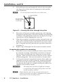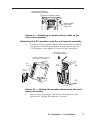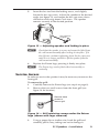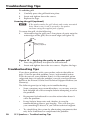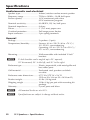
1
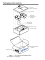
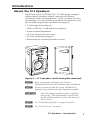
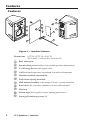
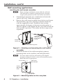
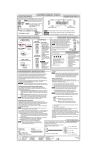
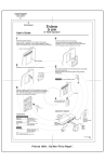
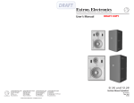
User’s Guide
SI 3 System INTEGRATOR™
Compact Full Range Surface Mount Speakers
68-1261-01
Rev. A
11 07
Packaging Information
Hex Tool
(plastic wrapped)
Top Foam
Speakers
(each plastic
wrapped)
Wall Mount
Assemblies
Speaker Rear Cover
Bottom Foam
Thick Single Wall
Packing
Product Label
Inst
Par
all
t No
.
33XX
206W
XX
X-XX Cei
X-01 ling
XX
-01
RE
Sp
eake
r
V.
Figure 1 — SI 3 speaker packaging details
SI 3 Speakers • Packaging
Introduction
About the SI 3 Speakers
The Extron System INTEGRATOR ™ SI 3 full range, compact,
surface mount speaker is ideally suited for classrooms,
conference rooms, and boardrooms. With a weather resistant
construction, it is also suitable for outdoor environments, and
has the following features (see below and page 2).
• 3" full range internal driver
• 75 Hz to 18 kHz, -10 dB frequency response
• 8 ohm nominal impedance
• 16 watts continuous pink noise
• 32 watts continuous program
• Internal driver overload protection circuit
Figure 2 — SI 3 speakers (with front grille removed)
N Refer to packaging information for location.
Carefully remove and check contents before installation.
N Extron recommends that the wiring installation be
performed by a professional audio equipment installer.
C
Use cable clamps to hold the cables in place for
strain relief. Trim back/insulate exposed cable
shields with heat shrink to reduce the chance of
short circuits.
N For "Troubleshooting Tips" see pages 10 and 11.
N For "Service Access" see page 9.
SI 3 Speakers • Introduction
1
Features
Features
5
6
1
11
10
7
2
8
3
4
9
Figure 3 — Speaker features
Dimensions: 8.75" H x 5.75" W x 5.61" D
(22.2 cm H x 14.6 cm W x 14.24 cm D)
a
b
c
d
e
f
g
h
i
j
k
2
Bass reflex port
Front locking access (allows for speaker position adjustment)
3" full range driver with paper cone
Grill and enclosure may be painted to match environment
Weather resistant construction
Push down spring terminals
Wall mount assembly with unique V-Lock™ system included
Back cover for use when speakers are not wall mounted
Hex tool
Extron logo (fits in grill to cover locking port access)
Front grill retaining screws (2)
SI 3 Speakers • Features
Installation
Installing the SI 3 Speakers
The Extron SI 3 speakers can be mounted on a surface, such as a
wall or post, or mounted in a bookcase, or on a shelf, and can be
used with any Extron product supporting audio.
N If the speakers are to be placed on a horizontal surface such
as a desk or shelf, attach the back cover to enhance the
speaker appearance.
RGBHV
Video
Extron
MLS 406SA
S-video
MediaLink Switcher
Projector
UT
TP
D OU
IFIE LEFT
PL
AM
HT
RIG
12V
Tx
DIO
AU L
2
1
DIO
AU
S
UT
INP
5
6
4
DIO
AU
IX
X/M
ST
AU
JU
AD dB
-42
TO
dB
+24
L
VE
E LE
LINMONO
L
S
UT
INP
3
4
UT
INP UT
EO
LIN
Rx
IR
C
LC
2/M
-23
RS EAMP
PR
A
B
/IR
Extron
SI 3
L
R
R
R
R
Surface-mount
Speakers
B
S
UT
TP G
OU
OR
NIT
MO
R
H
EO
VID
3
V
-240
100
T
OU
V
Y
S
UT
INP
C
0Hz
50-6
2
1
X.
MA
1.0A
DVD
VCR
Document Camera
PC
Laptop
w/ Audio
Figure 4 — Surface speaker application
Desktop or bookshelf applications
1.
For quick installation on a desktop or bookshelf, simply
place on a desk, shelf, or other flat surface as desired.
2.
Route the speaker wire (Extron recommends using
12-18 AWG) to the speakers.
3.
Strip the wire and connect the speakers as described in
"Wiring the speakers" on page 8.
SI 3 Speakers • Installation
3
Installation, cont’d
Wall mounting applications
Installing the wall mount assembly
N Before starting installation, ensure that the wall and
wall material are capable of supporting the combined
weight of the speakers and the wall mount assemblies.
1.
If mounting to drywall, use a stud locator to locate the
studs in the wall. Mark their position.
2.
Remove the wall mount assembly from the box and loosen
the central hex cap screw (turning it counter clockwise)
with the supplied hex tool. Rotate the front section
approximately 90 degrees to the rear mounting plate, as
shown in figure 5, and tighten the hex cap screw to lock the
front section in position. This makes the next steps easier
to perform.
Fasten the
wall mount plate
to the vertical
surface.
Rotate front
section 90°
Rear Mounting Plate
Figure 5 — Rotating and mounting the wall mount
assembly
3.
Mark the location of the wall mount plate's primary
mounting holes on the stud line, and drill pilot holes.
N For some surfaces the four alternative pilot dimples
(see figure 6) may be used to secure the assembly in place.
Mark and drill as appropriate.
Line of Stud
Alternative
Pilot Dimples
Primary
Mounting
Holes
Alternative
Pilot Dimples
Figure 6 — Mounting holes on the rear plate
4
SI 3 Speakers • Installation
4.
Mark the wall where the wire will pass through the plate,
and cut a small access hole large enough for the wire to
pass through without interference. Where the stud is
wider than the plate's access hole, cut the hole in the wall
to the left or right and directly alongside the stud (see
figure 7).
N Before cutting the hole in the wall, make sure the plate will
hide the hole after installation.
5.
Using compatible speaker wire (Extron recommends using
12-18 AWG), route the wire from the audio source to the
speaker location by the most convenient and safe route. If
the wiring is to remain hidden behind the wall, follow the
stud to where the small access hole has been cut, and feed
about two feet of wire out through the hole into the room.
If necessary, bend the wire behind the plate to align with
the hole in the plate (see figure 7). If possible, secure the
wire to the stud at various places. Allow enough freedom
of movement at the hole for speaker connection.
Approximate Stud
Line Behind Wall
Wall
Wall Stud
Cut an acess
hole alongside
the stud and
feed the speaker
wires though the
hole.
Bend wire to line up with
access hole in the plate.
Speaker Mounting Assembly
Figure 7 — Installing the wall mount assembly
N Extron recommends that the wiring installation be
performed by a professional audio equipment installer.
SI 3 Speakers • Installation
5
Installation, cont’d
6.
Pull sufficient wire up through the holes in the rear plate
(see figure 8) to allow ease of connection to the speaker
after installation.
N
Do not strip and connect the wire at this time.
Line of Stud
Pass the wires
through the plate
access hole.
Figure 8 — Passing the wire through the plate
7.
Place the wall mount assembly against the wall, aligning
the plate mounting holes with those drilled, and secure the
assembly with appropriate hardware (see figure 5) using a
screwdriver with an appropriate screw bit.
8.
When the assembly is securely in place, loosen the hex cap
screw (turn counter clockwise) and rotate the front section
back into a vertical position with the hex cap screw at the
top. Using the hex tool, turn the hex cap screw clockwise
to tighten it.
9.
Repeat steps 1 through 8 for the second assembly mount.
Preparing the speaker for mounting
1. If the back covers were installed previously, remove them
by carefully inserting a flat bladed screwdriver to loosen
the two lower locking tabs first, then one or more of the
top tabs. Take care not to crack or chip the cover or break
off the locking tabs. Lift away the cover as it comes free.
2.
At this point connect an optional seismic safety cable (not
supplied) to the rear of the speaker by looping it through
the hole on the box bracket and securing it (see figure 9).
Anchor the other end to a suitable secure point above the
speaker wall assembly mount.
C
The safety cable should be of sufficient strength
to support the full weight of the speaker and wall
mount assembly combined.
N Ensure that the cable is long enough to allow you to
connect the speaker wires and to manipulate the speaker
into position on the assembly mount.
6
SI 3 Speakers • Installation
Anchor this end to a
suitable secure point.
Seismic Safety Cable
Attach cable
here and
secure it.
Figure 9 — Attaching a seismic safety cable to the
rear of the speaker
Mounting the SI 3 speaker onto the wall mount assembly
3. Carefully lift the speaker above the wall mount assembly
and gently slide the speaker box bracket down into the
V-Lock groove (see figure 10) until it locks into place.
...and slide it down
into the V-lock groove.
Lift the speaker up to the
wall mount assembly....
Box
Bracket
Box
Bracket
V-Lock
Groove
V-Lock
Groove
Figure 10 — Sliding the speaker down onto the wall
mount assembly
4. Repeat steps 1 through 3 for the second speaker, then
proceed to "Wiring the speakers" section.
SI 3 Speakers • Installation
7
Installation, cont’d
Wiring the speakers
1.
2.
Strip approx. 15 mm (5/8").
When both speakers are in place,
carefully pull enough speaker wire
to reach to the terminals at the back
Twist the bared wire.
of the each speaker and strip the
ends of the wire approximately 5/8" (15 mm). Twist the
bare strands so that they are held firmly in the connectors.
Press down on the spring loaded terminals to open the
holes at the top. Observing the correct polarity, (positive
wire to , terminal and negative wire to . terminal)
insert the twisted ends into the open holes (see figure 11)
and release the springs to secure them. Push any loose
wire back into the wall.
C
Do not connect the speaker wires from one channel
in parallel (together) with wires of the other channel
on the same terminal.
Extron
Negative
Wire
INPUT
Push down on the spring terminals
at the back of the speaker, and insert
the wires. Release the springs to secure.
Positive Wire
Figure 11 — Inserting wiring into the terminals
3.
Turn on the audio source and any associated devices.
Follow the manufacturer's instructions to adjust the source
and device settings as desired to get the optimum audio
output for your speaker application. It may be necessary
to adjust the angle of the speaker (see steps 5 and 6 below)
to get the best audio coverage area for your application.
4.
To adjust the angle of the speaker, carefully remove the
Extron logo on the front of the speaker to expose the front
locking access (see figure 3, item b, for location). To do
this, carefully pry the logo away with your fingers or use a
small flat head screwdriver (see figure 12), taking care not
to damage the front grill or the logo.
Gently pry
away logo.
Figure 12 — Removing the logo from the front grill
8
SI 3 Speakers • Installation
5.
Insert the hex tool into the locking access, and slightly
loosen the hex cap screw. Adjust the speaker to the desired
angle (see figure 13), and torque the hex cap screw down
clockwise until snug, about 6 to 8 turns. The speaker
remains securely in the desired position.
Turn clockwise
to tighten.
Figure 13 — Adjusting speaker and locking in place
N Check that the speaker is secure and cannot be lifted from
the wall mount assembly after locking it into place. If it
does lift out, continue tightening down the hex cap screw
until it is no longer possible to lift the speaker from the
wall mount assembly.
6.
Replace the Extron logo, pressing it firmly into place.
N The Extron logo can be fitted either horizontally or
vertically
Service Access
In order to service the speaker it may be necessary to remove the
front grill.
To remove the grill:
1. Carefully remove the Extron logo (see step 4 on page 8).
2.
Remove the two small screws from the front grill (see
figure 14 for location).
Remove these
screws to
remove grill.
Figure 14 — Grill retaining screws under the Extron
logo (shown with logo removed)
3.
Using a paper clip or similar wire, hook the grill and
carefully pull it away, taking care not to damage it.
SI 3 Speakers • Installation
9
Troubleshooting Tips
To refit the grill:
1. Carefully press the grill back into place.
2. Insert and tighten down the screws.
3. Replace the logo.
Securing the grill (optional)
N If the speaker makes the grill vibrate and creates unwanted
noise when in use, it can be secured to the speaker
enclosure using the supplied pack of putty.
To secure the grill, do the following:
1. After removing the grill, press four pieces of putty onto the
outer edges of the grill, one on each edge (see figure 15).
Apply 4 pieces
of putty (supplied).
Figure 15 — Applying the putty to speaker grill
2. Press the grill firmly into place on the enclosure.
3. Insert and tighten down the two screws. Replace the logo.
Troubleshooting Tips
If you have problems with your speaker, refer to the table on
page 11 for the possible problem, cause, and remedial action.
If you do not see your problem listed, or if the remedial action
suggested does not cure the problem, consult your local Extron
dealer or the Extron S3 Sales and Technical Support Hotline (see
Warranty).
The following are tips to help you in troubleshooting:
10
•
Some symptoms may resemble others, so you may want to
look through all of the examples before attempting to solve
the problem.
•
Be prepared to backtrack in case the action taken doesn’t
solve the problem.
•
It may help to keep notes and sketches in case the
troubleshooting process gets lengthy. This will also give
you something to discuss if you call for technical support.
•
Try simplifying the system by eliminating components that
may have introduced or complicated the problem.
SI 3 Speakers • Troubleshooting Tips
Observed
Problem
Possible Cause(s) Remedial
Action
1 Speaker easily
lifted from mount
assembly
Locking hex cap
screw not tightened
enough
Following the steps on page 9,
tighten the hex cap screw until
it is not possible to remove the
speaker.
2 No sound heard
from speakers
Speaker cables
not connected or
damaged
Reconnect or replace speaker
cable. Check cable routing.
Output device
(e.g., amplifier)
Check that the output devices
are plugged in and powered on.
Check that all cables are
connected correctly.
Check that an output signal
is present. If present, change
cables and/or use a known
working set of speakers.
Check that volume settings are
adequately high.
Replace suspect devices with
known working devices. Retry
the system.
3
Output poor or
intermittent
4 Constant buzzing,
hissing, or
humming
5 Poor low
frequency output
Damaged cables or
faulty connection
Check cables and connections.
Reconnect or replace if needed.
Faulty device(s)
within sound
system
Check all devices. Swap out
and test with known working
devices to isolate interference
source. Replace faulty device(s).
System grounding
inadequate or
suspect
Check grounding to devices and
repair where needed.
Incorrect speaker
polarity connection
between multiple
speakers
Check polarity between
speakers. Incorrect polarity
(out of polarity) results in low
frequencies cancelling each other
out. Reverse polarity for each
speaker in turn until a greater
low frequency is obtained.
SI 3 Speakers • Troubleshooting Tips
11
Specifications
Audio/acoustic and electrical
Speaker type.................................... Indoor/outdoor surface mount speaker
Frequency range............................. 75 Hz to 18 kHz, -10 dB, half space
Power capacity............................... 16 W continuous pink noise
32 W continuous program
Nominal sensitivity........................ 83 dB SPL, 1W, 1m, half space
Nominal impedance...................... 8 ohms
Driver............................................... 3" (76.2 mm) paper cone
Overload protection....................... Full range power limiter
Input connector.............................. 2 pin spring terminals
General
Package............................................ 2 speakers (1 pair)
Temperature/humidity................. Storage: -40 to +158 °F (-40 to +70° C) /
10% to 90%, noncondensing
Operating: +32 to +122 °F (0 to +50° C) /
10% to 90%, noncondensing
Mounting......................................... Wall mountable with included V-lock™
brackets
N
V-lock brackets can be angled up to 20° upward,
35° downward, 30° to the left, and 30° to the right.
Enclosure type................................ Plastic, trapezoidal, with metal grille and
bass reflex ports
Grill material................................... Perforated steel, powder coat black
or white
Enclosure outer dimensions......... 8.75" H x 5.75" W x 5.6" D
(22.2 cm H x 14.6 cm W x 14.24 cm D)
Product weight............................... 4.0 lbs (1.8 kg) each
Shipping weight ............................ 13 lbs (6 kg) per pair with mounting kit
package
Warranty.......................................... 5 years parts and labor
N
All nominal levels are at ±10%.
N
Specifications are subject to change without notice.
12
SI 3 Speakers • Specifications
Extron’s Warranty
Extron Electronics warrants this product against defects in materials and workmanship
for a period of five years from the date of purchase. In the event of malfunction during
the warranty period attributable directly to faulty workmanship and/or materials, Extron
Electronics will, at its option, repair or replace said products or components, to whatever
extent it shall deem necessary to restore said product to proper operating condition,
provided that it is returned within the warranty period, with proof of purchase and
description of malfunction to:
USA, Canada, South America,
and Central America:
Extron Electronics 1001 East Ball Road
Anaheim, CA 92805, USA
Asia:
Extron Electronics, Asia
135 Joo Seng Road, #04-01
PM Industrial Bldg.
Singapore 368363
Europe, Africa, and the Middle East:
Extron Electronics, Europe
Beeldschermweg 6C
3821 AH Amersfoort
The Netherlands
Japan:
Extron Electronics, Japan
Kyodo Building
16 Ichibancho
Chiyoda-ku, Tokyo 102-0082
Japan
This Limited Warranty does not apply if the fault has been caused by misuse, improper
handling care, electrical or mechanical abuse, abnormal operating conditions or nonExtron authorized modification to the product.
If it has been determined that the product is defective, please call Extron and ask for an
Applications Engineer at (714) 491-1500 (USA), 31.33.453.4040 (Europe), 65.6383.4400
(Asia), or 81.3.3511.7655 (Japan) to receive an RA# (Return Authorization number). This
will begin the repair process as quickly as possible.
Units must be returned insured, with shipping charges prepaid. If not insured, you
assume the risk of loss or damage during shipment. Returned units must include the
serial number and a description of the problem, as well as the name of the person to
contact in case there are any questions.
Extron Electronics makes no further warranties either expressed or implied with respect
to the product and its quality, performance, merchantability, or fitness for any particular
use. In no event will Extron Electronics be liable for direct, indirect, or consequential
damages resulting from any defect in this product even if Extron Electronics has been
advised of such damage.
www.extron.com
Extron Electronics, USA
1230 South Lewis Street
Anaheim, CA 92805
800.633.9876 714.491.1500
FAX 714.491.1517
Extron Electronics, Europe
Beeldschermweg 6C
3821 AH Amersfoort, The Netherlands
+800.3987.6673 +31.33.453.4040
FAX +31.33.453.4050
Extron Electronics, Asia
135 Joo Seng Rd. #04-01
PM Industrial Bldg., Singapore 368363
+800.7339.8766 +65.6383.4400
FAX +65.6383.4664
© 2007 Extron Electronics. All rights reserved.
Extron Electronics, Japan
Kyodo Building, 16 Ichibancho
Chiyoda-ku, Tokyo 102-0082
Japan
+81.3.3511.7655 FAX +81.3.3511.7656