1
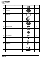
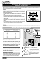
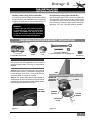
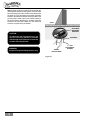
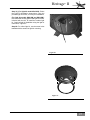
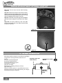
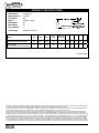
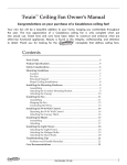
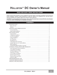
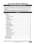
Heritage™ II Owner’s Manual READ AND SAVE THESE INSTRUCTIONS! Safety and the proper operation of your Casablanca fan both require a thorough knowledge of the product and proper installation. Therefore, before attempting to install and operate your Casablanca fan, read this Owner’s Manual completely and carefully. Retain this manual and other included documentation for future reference. CAUTION: To avoid possible electrical shock, make certain that electricity is turned off at the circuit breaker or fuse box before attempting any installation procedure. CONTENTS INTRODUCTION Parts Guide . . . . . . . . . . . . . . . . . . . . . . . . . . . . . . . . . . . . . . . . . . . . . . . . . . . . . . . . . . . . . . . . . . . . . . . . . . . . . 3 Before You Start . . . . . . . . . . . . . . . . . . . . . . . . . . . . . . . . . . . . . . . . . . . . . . . . . . . . . . . . . . . . . . . . . . . . . . . . . 5 Safe Use . . . . . . . . . . . . . . . . . . . . . . . . . . . . . . . . . . . . . . . . . . . . . . . . . . . . . . . . . . . . . . . . . . . . . . . . . . . . . . . 5 MOUNTING RECOMMENDATIONS General Guidelines . . . . . . . . . . . . . . . . . . . . . . . . . . . . . . . . . . . . . . . . . . . . . . . . . . . . . . . . . . . . . . . . . . . . . . . 6 Sloped Ceiling Installations . . . . . . . . . . . . . . . . . . . . . . . . . . . . . . . . . . . . . . . . . . . . . . . . . . . . . . . . . . . . . . . . . 6 FAN INSTALLATION Getting Started . . . . . . . . . . . . . . . . . . . . . . . . . . . . . . . . . . . . . . . . . . . . . . . . . . . . . . . . . . . . . . . . . . . . . . . . . . 7 Crossbar Mounting Bracket Installation . . . . . . . . . . . . . . . . . . . . . . . . . . . . . . . . . . . . . . . . . . . . . . . . . . . . . . . 7 Lag Screw Installation (required) . . . . . . . . . . . . . . . . . . . . . . . . . . . . . . . . . . . . . . . . . . . . . . . . . . . . . . . . . . . . 9 Canopy Installation . . . . . . . . . . . . . . . . . . . . . . . . . . . . . . . . . . . . . . . . . . . . . . . . . . . . . . . . . . . . . . . . . . . . . . . 9 Fan Preparation . . . . . . . . . . . . . . . . . . . . . . . . . . . . . . . . . . . . . . . . . . . . . . . . . . . . . . . . . . . . . . . . . . . . . . . . 10 Hanging the Fan . . . . . . . . . . . . . . . . . . . . . . . . . . . . . . . . . . . . . . . . . . . . . . . . . . . . . . . . . . . . . . . . . . . . . . . . 11 Canopy Electrical Connections . . . . . . . . . . . . . . . . . . . . . . . . . . . . . . . . . . . . . . . . . . . . . . . . . . . . . . . . . . . . . 11 Canopy Hatch Installation . . . . . . . . . . . . . . . . . . . . . . . . . . . . . . . . . . . . . . . . . . . . . . . . . . . . . . . . . . . . . . . . . 11 Blade Installation . . . . . . . . . . . . . . . . . . . . . . . . . . . . . . . . . . . . . . . . . . . . . . . . . . . . . . . . . . . . . . . . . . . . . . . . 12 Switch Housing and End Cap Installation . . . . . . . . . . . . . . . . . . . . . . . . . . . . . . . . . . . . . . . . . . . . . . . . . . . . . 14 Light Fixture Installation (optional) . . . . . . . . . . . . . . . . . . . . . . . . . . . . . . . . . . . . . . . . . . . . . . . . . . . . . . . . . . 15 4 - Speed Operation . . . . . . . . . . . . . . . . . . . . . . . . . . . . . . . . . . . . . . . . . . . . . . . . . . . . . . . . . . . . . . . . . . . . . 18 TROUBLESHOOTING TIPS . . . . . . . . . . . . . . . . . . . . . . . . . . . . . . . . . . . . . . . . . . . . . . . . . . . . . . . . . . . . . . . . 19 CARE RECOMMENDATIONS . . . . . . . . . . . . . . . . . . . . . . . . . . . . . . . . . . . . . . . . . . . . . . . . . . . . . . . . . . . . . . . 19 PRODUCT SPECIFICATIONS . . . . . . . . . . . . . . . . . . . . . . . . . . . . . . . . . . . . . . . . . . . . . . . . . . . . . . . . . . . . . . . 20 PN C1943001 RL1210 1 PLEASE INSPECT ALL PACKAGING PRIOR TO DISCARDING! Your Casablanca fan was crafted with pride and care and inspected thoroughly prior to shipment. Before you begin to assemble and install your Casablanca fan, remove all parts from the carton and check them against the Parts Guide in this manual. Make sure all parts are included in the box using the Parts Guide on the following pages. If there are missing or broken parts: Call 1-888-227-2178 Monday through Friday, 8 a.m. to 4:30 p.m. CST. Your request will be handled immediately. Replacement parts will be sent to you via Federal Express. Proper Parts Handling Do not remove lightbulbs from their packaging until you are ready to install them. Before discarding packaging materials, be certain that all parts have been removed. Use a clean, dry paintbrush to remove small Styrofoam pieces that may remain after unpacking. Do not brush Styrofoam into wiring cavities. The blades in each pack are matched for equal weight to assure smooth fan operation. If more than one fan is being installed, do not mix blades from different cartons. Always turn power to the ceiling fan OFF before replacing lightbulbs or working on your fan. Never insert anything into the path of the fan blades while the fan is in operation. Never install a fan over a pool or spa. Never operate a fan that has been damaged in any way. Install the fan according to the instructions in this manual. If the fan does not work: Refer to the Troubleshooting Tips in this Owner’s Manual. Call Technical Support at 1-888-227-2178. Contact your local Authorized Service Center. Our Web site at www.casablancafanco.com contains additional information on Casablanca products, troubleshooting, and Authorized Dealer or Service Centers. Please do not return this product to the store. When cleaning, painting, or working near your fan, be cautious of the fan and blades. RECORD MODEL AND SERIAL NUMBERS BEFORE INSTALLATION! Please take a moment to locate the model number and serial number from your fan (see below) and record this information on the Warranty page inside the front cover of your Owner’s Manual if it does not appear there already. These numbers are found on the motor identification plate affixed to the fan motor in the location shown below: Motor Identification Plate Heritage® II TYPE HANGER TYPE Memphis, TN SERIAL No.: DJ06 2237 C19xxxK 2 DJ01 1151 MODEL #C19xxxK Serial Number Model Number Heritage II TM Parts Guide Item # Description Picture (not to scale) Quantity 1. Crossbar-Mounting Bracket 1 2. Rubber Gasket and Mounting Plate 1 3. Motor Housing 1 4. Lag Screw and Washer 1 5. Canopy 1 6. Hanger Screw Pack 1 7. PermaLock Downrod and Ball Assembly 1 8. Pole Cover 1 9. Phillips Screwdriver 1 10. Allen Wrench and Set Screw 1 11. Blades (packed seperately) 5 12. Blade Badge Screws 21 13. Blade Badges 5 14. Blade Irons 5 3 Item # Description Picture (not to scale) Quantity 15. Blade Iron Screws 6 16. Switch Housing 1 17. Light Kit Gasket 1 18. Switch Housing Gasket 1 19. Adapter Plate 3 20. Adapter Plate Screws 4 21. Switch Housing Screws 3 22. Cover Plate Cap 1 23. Cover Plate Screws 1 24. End Cap Plug Button 1 25. Balancing Kit 1 26. Light Kit Screws 3 27. Light Pull Chain Switch 1 28. Fandangle 3 4 Heritage II TM INTRODUCTION BEFORE YOU START • CAUTION: RISK OF ELECTRICAL SHOCK! Installation is to be in accordance with the National Electrical Code, ANSI/NFPA 70-1999 and local codes. If you are unfamiliar with the wiring codes, you should use a qualified electrician. To avoid overheating and possible damage to other equipment, do not install control to a receptacle, fluorescent light fixture, motor-operated appliance, or transformer-supplied appliance. • This fan is designed to be installed on an existing electrical outlet box. The outlet box must be UL Listed for ceiling fan installations. If it is not, a new box must be installed. Casablanca extension poles are available for sloped or high ceiling installations. • This ceiling fan requires a grounded electrical supply of 120 VAC, 60 Hz and a minimum 15 amp circuit. The maximum current requirement for the fan with light fixture is 3.1 amps. The fan uses about 1.1 amp or 132 watts. Maximum light current is about 2.0 amps or 190 watts of lighting. • Where wire nuts are employed, be sure all bare wires are within the connectors. When installing the canopy hatch, make sure all wires are within the canopy and that no wires are being pinched. • WARNING: Do not bend the blade brackets when installing the brackets, balancing the blades, or cleaning the fan. Do not insert foreign objects in between the rotating fan blades. • The fan must be supplied with 1 independent 120V AC supply wire and 1 neutral wire to provide power for the fan. • This fan is suitable for wet locations when installed in a GFCI protected branch circuit. • Use only with light kits marked "suitable for use in wet locations". Unpacking Before assembling and installing your ceiling fan, remove all parts from the shipping cartons and check them against the parts listed in the Parts Guide. Before discarding packaging materials, be certain that all parts have been removed. For best performance and for your warranty to be valid, use only genuine Casablanca blades, light fixtures, and accessories. SAFE USE • The blades in each pack are matched for equal weight to assure smooth fan operation. If more than one fan is being installed, be careful not to mix blades from different cartons. Fuse Box (Remove fuse for the circuit you will be working on) Circuit Breaker (Trip breaker for the circuit you will be working on) • Inspect the contents of your carton for possible shipping or handling damage. If parts are missing or damaged, call 1-888-227-2178. • It is always a good idea to have an assistant to help with the installation. • When cleaning, painting, or working near your fan, be very careful of the fan and blades. Always turn the power OFF to the ceiling fan before working on it or replacing lightbulbs. • Never insert anything into the path of the fan blades while the fan is in operation. from tip of blade to wall 18" • Never install a fan over a pool or spa. • Never operate a fan that has been damaged i n a n y w a y. F o r a s s i s t a n c e i n o b t a i n i n g service, call Casablanca Fan Company at 1-888-227-2178 or contact your local authorized Casablanca dealer. 84" from bottom edge of blade to floor Dimensions indicated are the minimum allowable for proper installation. 5 MOUNTING RECOMMENDATIONS GENERAL GUIDELINES Before mounting your Casablanca fan, read the following helpful recommendations. The location of the fan, air circulation, and fan size are all important factors to consider before installation. Location Ceiling fans have practical uses in almost every room in your home. We suggest you follow these mounting recommendations as you decide where to install your Casablanca fan. • For safety reasons, the fan blades must be a minimum of 7' above the floor. • Do not locate the fan in a doorway or above a swinging door. • In bedrooms, fans work best when mounted above the foot of the bed. • Over pool tables, be sure to provide plenty of clearance to avoid damage from pool cues. • In kitchens, be sure to allow for open cupboard doors to clear the fan blades. • Do not install a fan close to or over a pool or spa. High humidity combined with corrosive gases will destroy the finish and warp the blades. Fan Size Variable fan speed capability permits the use of a full-size 60" fan even in smaller rooms. For very large rooms, two fans may be needed. SLOPED CEILING INSTALLATIONS SUGGESTED EXTENSION DOWNROD LENGTHS Ceiling Height 9' 0" 9' 6" 10' 0" 11' 0" 12' 0" 13' 0" 14' 0" 15' 0" Downrod Length Extension Downrod 5" 5" 12" 18" 24" 36" 48" 60" Maximum Hang-Tru® angle 32º Blades must be a minimum of 7 feet above the floor 7' minimum When to Use an Extension Downrod For optimum performance and appearance, an extension downrod should be used with your Casablanca fan when installing on high (cathedral) ceilings or sloped ceilings. Casablanca offers standard downrods in increments of 6" up to 60". See your Authorized Casablanca Dealer for details. NOTE: The fan may wobble or vibrate if pole length is not long enough and the inside blade is too close to the downslope or side wall. Using a longer downrod will usually solve the problem. EXAMPLE 1 EXAMPLE 2 Calculation of Ceiling Angle Use the tear-off Ceiling Angle Template card inserted in this manual. It provides you with a simple “go” or “no go” for installing your fan on a sloped ceiling. 6 EXAMPLE 3 This slope is less than 32º. It is OK to install your fan. This slope is 32º. This is the maximum slope that will allow the fan to hang straight down. It is OK to install your fan. This slope is more than 32º. Your fan will not hang straight down. Contact your local Authorized Casablanca Dealer. Heritage II TM FAN INSTALLATION GETTING STARTED Installing a New Ceiling Fixture Outlet Box Using Existing Ceiling Fixture Outlet Box If you do not have an existing fixture located where you wish to place your Casablanca fan, an approved ceiling fixture outlet box must be installed and wired. After turning the power OFF at its source (either the circuit breaker or fuse box), lower the old fixture and disconnect the wiring. Check the ceiling fixture outlet box to be sure it is marked “Approved for Ceiling Fan Mounting.” If it is not, a new box must be installed. WARNING! To reduce the risk of fire, electrical shock, or personal injury, mount to outlet box marked “Acceptable Fan Support of 22.7 kg (50 lbs.) or less” using the mounting hardware provided with the outlet box. CROSSBAR MOUNTING BRACKET INSTALLATION CEILING HARDWARE (not to scale) Crossbar Mounting Bracket Rubber Gasket Mounting Plate Lag Screw and Washer (1) 1" x 8-32 Roundhead Screws and Washers (2) Wire Nuts (4) Note: After removing the old fixture, check the outlet box to ensure that it is supported by a joist or beam across its upper surface. If not, a 2 x 4 stud must be installed. Step 1a. Remove the knockout plug in the center of the outlet box or drill a 1/2-inch hole for the lag screw to pass through. Then drill a 1/4-inch guide hole into the joist or beam to a depth of 3 inches. Step 1b. The rubber gasket has a cutout already in the gasket for the wires as shown in Figure #1. Route the outlet box wires through the rubber gasket and the mounting plate as shown in Figure #2. CUTOUT FOR WIRES JOIST CEILING FANAPPROVED WIRING BOX RUBBER GASKET / 1 2" HOLE CEILING WIRING MOUNTING PLATE Figure #1 Figure #2 7 Step 1c. After routing the outlet box wires through the rubber gasket and the mounting plate, route the outlet box wires along side of the crossbar mounting bracket as shown in Figure #3. Attach the crossbar mounting bracket to the outlet box with the screws provided. First you will need to make a hole in the rubber gasket for the screws before attaching the crossbar mounting bracket to the outlet box. Make sure the outlet box wires are not pinched by the washer. JOIST CROSSBAR MOUNTING BRACKET CAUTION: To reduce the risk of personal injury, use only the mounting hardware provided with the approved outlet box to install the crossbar mounting bracket. WASHERS WARNING! GREEN GROUND WIRE Support directly to building structure only. Figure #3 8 1" x 8-32 ROUNDHEAD SCREWS Heritage II TM LAG SCREW INSTALLATION (REQUIRED) Step 2. Pass the lag screw through the center hole of the crossbar mounting bracket and screw into the guide hole. Tighten until the outlet box is mounted firmly to the beam. This box must be secured to the ceiling firmly. CANOPY INSTALLATION CANOPY HARDWARE (not to scale) Canopy Hatch Canopy Canopy Screws and Lock Washers (5) Phillips Screwdriver Step 3. Attach the canopy to the crossbar mounting bracket with three of the 8-32 x 21/2" long canopy screws and lock washers provided with your Casablanca fan. Tighten using the provided screwdriver until snug against the ceiling. NOTE: On sloped ceilings, align the canopy opening with the top or peak of the room. CANOPY CANOPY SCREWS LOCK WASHERS 9 FAN PREPARATION PERMA•LOCK™ HARDWARE AND TOOLS NEEDED (not to scale) 5"Perma•Lock™ Downrod and Ball Assembly Pole Cover Set Screw IMPORTANT SAFETY INFORMATION: Allen Wrench PAPER MOTOR SHIELD Before starting the installation of your ceiling fan, install the threaded downrod into the motor coupling and lock the assembly. Figure #1 MOTOR WIRES (LEAVE AT LEAST 6" LONG) Prepare for fan installation as follows: Step 4a. Remove the paper shield (Figure #1) from the motor. POLE COVER Step 4b. Locate the Set Screw as shown in Figures #2 and #3. If the end of the Set Screw can be seen within the motor coupling as shown in Figure #3, you will need to unscrew the Set Screw so that the tip of the Set Screw does not remain in the path of the downrod. TAPERED THREAD SET SCREW Figure #2 Step 4c. Slide the pole cover on to the downrod, then route the wires through the 5" Perma•Lock downrod and ball assembly as shown in Figures #2 and #4. Insert the downrod into the motor coupling and turn it clockwise until it stops turning as shown in Figure #4, ensuring that the downrod has bottomed out. TIP OF SET SCREW ALLEN WRENCH TIP: The downrod has a tapered thread as shown in Figure #4 that is designed to lock completely when installed correctly. Figure #3 Step 4d. Tighten the Set Screw with the Allen wrench as shown in Figure #4 to ensure safe operation of your fan. If it is tight enough, you should not be able to turn the downrod counterclockwise with your hands. If in doubt, tighten the Set Screw with the Allen wrench until you cannot turn it any further. PERMA•LOCK™ DOWNROD AND BALL ASSEMBLY SET SCREW ALLEN WRENCH CAUTION: Failure to fully screw in the downrod all the way into the motor coupling may cause the fan to separate from the downrod and fall during normal operation. Figure #4 10 PERMA•LOCK™ DOWNROD AND BALL ASSEMBLY MOTOR COUPLING MOTOR HOUSING ASSEMBLY Heritage II TM HANGING THE FAN Step 5a. To hang the fan body in the canopy, hold the fan body firmly and insert the ball into the canopy opening. Check that no wires are pinched. Rotate the fan body until the slot in the ball fits into the pin opposite the canopy opening. BALL Step 5b. Trim excess motor wires, leaving at least 6 inches above the downrod. Strip ½-inch insulation from the end of each wire using a wire stripper (available at your local hardware store). SLOT PIN CANOPY ELECTRICAL CONNECTIONS Step 6. Attach the fan wires to the ceiling fixture outlet box wiring by placing the bare ends of the wires side by side and then securing with a wire nut. Test that the connection is secure by pulling on the wire nut. Connect in this order: • GREEN leads from mounting plate and downrod assembly of fan to GROUND conductor of power source. Secure with wire nut. • WHITE wire from fan to white NEUTRAL wire in ceiling fixture outlet box. Secure with wire nut. WIRE NUT RED AND BLUE WIRES • BLACK power wire from fan to BLACK power wire in ceiling outlet box. Secure with wire nut. 2 BLACK WIRES • BLUE D1-OPTION wire from fan to RED power wire (second hot wire) in ceiling outlet box. Secure with wire nut. 2 WHITE WIRES After making the wire connections, the wires should be spread apart with the grounded conductor and the equipment-grounding conductor on one side of the outlet box and the ungrounded conductor on the other side of the box. The splices after being made should be turned upward and pushed carefully into the outlet box. 3 GREEN WIRES NOTE: If the color of your ceiling wires differs from that described, consult an electrician. CANOPY HATCH INSTALLATION Step 7a. Tuck the wires into the canopy with the wire nuts pointed upwards, so that the WHITE and BLACK wires are on opposite sides of the canopy and all wires are clear of the canopy opening. Step 7b. Install the canopy hatch with the last canopy screw and lock washer using the provided screwdriver. To do this, tilt the fan body away from the hatch opening. Tighten the screws firmly. Step 7c. Straighten the fan, then check to ensure that there is no movement between the canopy and the ceiling or the downrod and the ball assembly. CANOPY HATCH CANOPY CANOPY SCREW & WASHER 11 BLADE INSTALLATION BLADE HARDWARE (not to scale) Blades (5) (packed separately) Blade Irons (5) Blade Iron Screws (11) Blade Badges (5) Blade Screws (21) Phillips Screwdriver NOTE: Blades are packaged separately based on blade style. For illustrative purposes, the BL-ADK-RA (Adirondack Reclaimed Antique) blades are shown. Please use the instructions below for all three blade types. Step 8. Remove the five shipping blocks, washers, and screws as shown in Figure #1. DO NOT discard the five screws; you will need them for installing the blades onto the fan. SHIPPING BLOCK Attach Blade Irons Step 9. Attach a blade to a blade iron by first pressing the blade badge onto the blade, then attaching the blade iron using four blade screws as shown in Figure #1. Using the provided screwdriver, tighten securely by hand only. Repeat for each blade assembly. Figure #1 BLADE IRON BLADE Blade Installation Step 10. Before attempting to attach the blades, review Figure #3 for blade placement on the blade holder adapter ring. The numbers and lines show screw placement when attaching the five blade irons and blades assemblies to the fan. When placing the blades on the adapter ring, each blade iron will cover one of the five adapter ring mounting screws as shown. BLADE BADGE Figure #2 BLADE BADGE SCREWS BLADE HOLDER ADAPTER RING Figure #3 12 Heritage II TM Blade Installation Step 11. Attach a blade/blade iron assembly to the blade ring by using two blade iron screws provided. Place the end of the blade iron on the blade holder adapter ring as shown in Figure #4. Insert the screws one by one using the provided screwdriver. Tighten securely by hand only. Repeat for each blade/blade iron assembly until all five blades are attached to the fan as shown in Figure #5. BLADE / BLADE IRON ASSEMBLY BLADE HOLDER ADAPTER RING CAUTION: BLADE IRON SCREW Figure #4 Blade screws must be tightened securely before operating the fan. Figure #5 13 SWITCH HOUSING AND END CAP INSTALLATION SWITCH HOUSING HARDWARE (not to scale) Switch Housing Switch Housing Gasket Light Kit Gasket Adapter Plate Cover Plate Cap Fandangle (3) Cap Plug Phillips Screwdriver Switch Housing Screws (3) Adapter Plate Screws (4) Cover Plate Screw (1) Light Kit Screws (3) Light Kit Pull Chain (1) Switch Housing Installation Step 12a. Place the switch housing gasket against the adapter plate and partially install two of the three switch housing screws onto the switch housing adapter plate as shown in Figure #1. Step 12b. Thread the Molex Plug through the hole in the center of the switch housing and align the two keyholes with the two screws that were installed on the switch housing adapter plate. Place the switch housing over the two screws and rotate it clockwise so that the two screws are holding the switch housing as shown in Figures #2 and #3. Step 12c. Align the screw hole on the switch housing with the screw hole in the switch housing plate and insert the third screw as shown in Figure #3. Then tighten all three screws with the provided screwdriver. Figure #2 SWITCH HOUSING GASKET SWITCH HOUSING SCREWS Figure #1 14 Figure #3 SWITCH HOUSING SCREWS Heritage II TM Step 12d. Plug the male Molex plug into the female Molex plug, aligning color and letters. NOTE: The Molex plug will only connect if the letters and colors are matched on both plugs. Do not force the plug together. MOLEX PLUG Figure #4 LIGHT FIXTURE INSTALLATION (OPTIONAL) Step 13. If you have purchased a Heritage™ II compatible light fixture for your fan (KGC10W, KGC12W, or KGC19W), you will need to prep your fan for this installation. Continue using these instructions until otherwise noted. If you are not installing a light kit, skip to step 14. Step 13a. Remove the plug from the switch housing. Figure #1. Step 13b. Remove the Cut wire sleeves for the included light switch and unscrew the knurl nut. Figure #2. Figure #1 KNURL NUT CUT WIRE SLEEVES Figure #2 15 Step 13c. Locate the single blue wire labelled "Connect Light Kit Black Wire Here" and the white wire labelled "Connect Light Kit White Wire Here." in the switch housing and remove the wire caps Step 13d. Feed the light switch pull chain and the end of the light switch through the hole in the switch housing. Figure #3. Step 13e. Feed the knurl nut back over the beaded chain and screw onto the light switch. Step 13f. Connect 1 blue wire from the light switch to the blue wire previously exposed from the fan and secure with the wire nut removed from it. Figure #3. Step 13g. Feed the unattached blue wire from the light switch and the unattached white wire from the fan through the hole in the adapter plate. Figure #6. Step 13h. Tuck all wires into the switch housing. Figure #5. Step 13i. Find the keyed slots on the switch housing, and the notches on the adapter plate. Line these up and assemble the adapter plate to the switch housing with the 4 adapter plate screws. Figure #4 and #5. BLUE WIRES LIGHT SWITCH Figure #3 TUCK IN WIRES ADAPTER SCREWS Figure #4 16 Figure #5 KEY SLOTS Heritage II TM Step 13j. (For light kit model KGC12W): Follow the Light Kit installation instructions, using the provided light kit screws, to finish your installation. (For light kit models KGC10W and KGC19W): Use the switch housing gasket and light kit screws, included with the fan, to install the outdoor light kit. Continue light kit installation using the light kit instructions. Figure #7. Step13k. For either light kit, use the screw holes labelled with the arrows for light kit mounting. Figure #6 Figure #7 17 INSTALLATION WITHOUT OPTIONAL LIGHT KIT Step 14a. Tuck all wires into the switch housing. Figure #1. Step 14b. Find the keyed slots on the switch housing, and the notches on the adapter plate. Line these up and assemble the adapter plate to the switch housing with the 4 adapter plate screws. Figure #1. Step 14c. Place the cover plate cap onto the adapter plate and secure using the Cover Plate screw. Figure #2 Step 14d. Line up the notches on the cover plate screw to the slots in the Cover Plate Cap and snap into place. Figure #2. Figure #1 Figure #2 4 - SPEED OPERATION Pull-chain switches on the fan control the fan and lights. Using the fan control pull-chain switch: Fan off OPTIONAL LIGHT PULL at start. CHAIN SWITCH First pull: fan ON, High speed Second pull: Medium speed Third pull: Medium Low speed Fourth pull: Low speed Fifth pull: Fan OFF The sequence of Light pull chain as follows: Light off at Start Direction of blade rotation is controlled by the reverse pull chain on the side of the switch housing. No changes in household wiring are required. 18 REVERSE PULL CHAIN SWITCH OPTIONAL LIGHT PULL CHAIN Heritage II TM TROUBLESHOOTING TIPS Please refer to this troubleshooting guide before requesting service or contacting your dealer for assistance. PROBLEM POSSIBLE REMEDIES Fan wobbles or shakes excessively • Be sure the canopy pin is set properly into the slot on the ball. • Check that the bladeholders have not been bent during installation and the blades are balanced. • The hanger bracket and/or the ceiling outlet are attached too loosely. Make sure the hanger bracket is attached tightly to the ceiling outlet box and the downrod assembly is secured firmly. • The downrod is attached to the downrod base too loosely. Make sure all the screws are securely tightened. Fan is noisy during operation • Tighten the canopy screws and mounting plate assembly. Make sure the wire nuts inside the canopy and switch housing are not touching the metal parts and that they have not fallen off the wire splices. Tighten as necessary. • Tighten the blade holders to the direct drive motor and the blades to the bladeholder screws. • Make sure all the screws in the motor housing are snug but not overly tight. • Check and tighten the light fixture retaining screws, glass shade screws, and/or lightbulb(s). Fan does not run on low speed • If fan is new, it may need to be “broken in.” Run at high speed for several days. CARE RECOMMENDATIONS Fan Finishes • For cleaning, a soft brush or lint-free cloth should be used to prevent scratching the finish. • A vacuum cleaner brush nozzle can remove heavier dust. • Surface smudges or an accumulation of dirt and dust can be removed easily using a mild detergent and slightly dampened soft cloth. An antistatic agent may be used, but never use abrasive cleaning agents as these will damage the finish. Blades • Wood-finish blades should be cleaned with a furniture polishing cloth. Occasionally, a light coat of furniture polish may be applied for added protection and beauty. • For painted and high-gloss blades, surface smudges or an accumulation of dirt and dust can be removed easily using a mild detergent and slightly dampened soft cloth. An antistatic agent may be used, but never use abrasive cleaning agents as these will damage the finish. No Need for Lubrication • Never lubricate this fan! The precision motor at the heart of your Casablanca fan features sealed bearings that are lubricated for life. • Do not attempt to oil the motor. For questions or to locate the nearest Casablanca Authorized Service Center call toll free: 1-888-227-2178 or visit us on the web at: www.casablancafanco.com 19 PRODUCT SPECIFICATIONS Model Name:Heritage™II Model Number: C19xxxK ETL Rating: Wet Motor: XTR200™ 30mm Blade Span: 60" Blade Pitch: 14° No. of Blades: 5 Technology: 4-Speed Pull Chain Weight (lbs) Speed* (rpm) Airflow* (cfm) Electricity Use* (watts) Airflow Efficiency* (cfm/watt) A B C D E BL-ADK-RA (Adirondack Reclaimed Antique) 39 167 7,179 98 74 14.7 15.4 2.9 16 5.6 BL-TPW-WB (Tropical Wicker Weathered Bronze) 47 155 6,422 97 66 15.3 15.4 2.9 16 5.6 Motor with Heritage™ Compatible Blades * = At high speed This device complies with RSS-210 of Industry Canada. Operation is subject to the following two conditions: (1) this device may not cause interference, and (2) this device must accept any interference, including interference that may cause undesired operation of the device. 1. This device complies with part 15 of the FCC Rules. Operation is subject to the following two conditions: (1) this device may not cause harmful interference, and (2) this device must accept any interference received, including interference that may cause undesired operation. 2. This equipment has been tested and found to comply with the limits for a Class B digital device, pursuant to Part 15 of the FCC Rules. These limits are designed to provide reasonable protection against harmful interference in a residential installation. This equipment generates, uses and can radiate radio frequency energy and, if not installed and used in accordance with the instructions, may cause harmful interference to radio communications. However there is no guarantee that interference will not occur in a particular installation. If this equipment does cause harmful interference to radio or television reception, which can be determined by turning the equipment off and on, the user is encouraged to try to correct the interference by one or more of the following measures: Reorient or relocate the receiving antenna, Increase the separation between the equipment and receiver, Connect the equipment into an outlet on a circuit different from that to which the receiver is connected. Consult the dealer or an experienced radio/TV technician for help. Note: Any changes or modifications to the transmitter or receiver not expressly approved by Casablanca Fan Company may void one’s authority to operate this remote control. 20