1
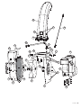
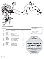
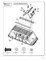
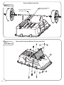
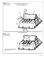
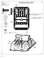
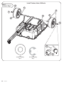
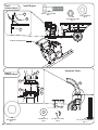
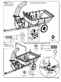
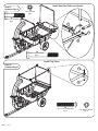
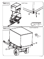
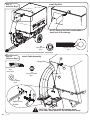
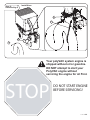
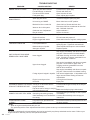
OWNER'S MANUAL
PolyVAC SystemTM
MODEL:
LVS-33 BH
LVS-33 BHK
LVS-33BH PolyVAC System fits the following
mower deck sizes of current tractor models:
• John Deere 42'', 48'' & 54'' • MTD 38'', 42'' & 46''
• John Deere ''X'' Series - 42'', 48'' , 54'' & 62''
• Murray 40'', 42'' & 46''
• Troy-Bilt 42'', 42''
• Craftsman 42'', 46",48'' & 50'' • Bolens 38'' & 42''
• Cub Cadet 38'', 42'' 44''50" • Stanley 42'' & 46''
• Husqvarna 46'', 48" & 54"
Assembly
Installation
Operation
Repair Parts
For use with
Lawn/Garden Tractors
NOT recommended for zero turn Radius (ZTR) mowers.
Congratulations on your purchase! Your Lawn-Vac will require significant assembly time. Depending
on your skills; you should plan on 4 to 8 hours for assembly. Please call us at 877-728-8224 if you have
questions regarding the assembly or operation of your Lawn-Vac.
Note: Warranty registration required! Please make sure you send in the warranty card with required
information and record the serial numbers below.
Serial Number:
Engine Number:
For the latest product updates and setup tips:
Visit us on the web!
www.brinly.com
Important: This manual contains information for the safety of
persons and property. Read it carefully before assembly and
operation of the equipment!
L-1771-D
CONGRATULATIONS on your new Brinly-Hardy Lawn Vac
System! Your Lawn Vac has been designed, engineered
and manufactured to give you the best possible
dependablility and performance.
Should you experience any problem you can not easily
remedy, please do not hesitate to contact our knowledgable
customer service department toll-free at 1-877-728-8224.
CUSTOMER RESPONSIBILITIES
Please read and retain this manual. Familiarize yourself
with the entire manual before begining and verify that all
hardware is present. And please, always observe the
"Safety Rules". Read and Observe the "Safety Rules".
Follow a regular schedule in maintaining, caring-for and
using your Brinly-Hardy Lawn Vac System.
TABLE OF CONTENTS
CUSTOMER RESPONSIBILITIES...................................2
SAFETY............................................................................2
HARDWARE.....................................................................3-4
PARTS LIST............... ......................................................4-10
ASSEMBLY ......................................................................11-23
TRACTOR PREPARATION..............................................24-26
OPERATION & USE.........................................................27
CONVERSION TO GARDEN CART.................................28
MAINTENANCE & STORAGE..........................................29
TROUBLE SHOOTING GUIDE........................................30
RULES FOR SAFE OPERATION
See tractor equipment owner's manual for safe operation of
the equipment.
STOP ENGINE when servicing, cleaning, or installing the
hose or chute.
NEVER operate the blower without chutes and hoses
securely in place.
NEVER operate the engine unless it is firmly attached to the
Lawn Vac chassis.
NEVER open canopy unless blower engine is stopped.
ALWAYS wear protective eyewear.
DO NOT STAND behind cart in the exhaust discharge area
when blower engine is running!
ALWAYS keep shields, guards, and hoses securely
attached.
NEVER attempt to clear a clog with the engine running.
BURNS can be caused by hot exhaust.
FIRES can be started by build-up of debris and dirt on the
engine and surrounding areas. Keep your unit clean.
NEVER fill the gas tank with the engine running. Allow time
for cooling before refueling.
Never operate the mower unless the grass deflector or the
deck adapter and hose provided with your Lawn Vac are in
place.
Know controls and how to stop quickly, READ THE
TRACTOR OWNER'S MANUAL.
Do not carry passengers. Keep children and pets a safe
distance away.
Do not allow children to operate the vehicle, do not allow
adults to operate without proper instruction or without having
read the owner's manual.
Always wear substantial footwear. Do not wear loose fitting
clothing that can get caught in moving parts.
Do not carry passengers. Keep children and pets a safe
distance away.
Keep your eyes and mind on your tractor/attachment and
area being covered. Do not let other interests distract you.
Do not drive close to creeks, ditches and public highways.
Do not exceed 4 mph. Not for highway use.
Stay off steep slopes and grades.
Stay alert for holes in the terrain and other hidden hazards.
Do not load cart with more than 650 pounds.
Watch out for traffic when crossing or near roadways.
Do not allow others near the equipment when operating
equipment.
Keep the vehicle and attachment in good operating condition
and keep safety devices in place.
Heavy loads will affect vehicle braking and stability. Consult
your tractor owner’s manual.
Keep all nuts, bolts and screws tight to be sure the
equipment is in safe working condition.
Due to the extended wheelbase of the Lawn Vac, turning will
require more area than normal conditions.
The vehicle and attachment should be stopped and
inspected for damage after striking a foreign object. The
damage should be repaired before restarting and operating
the equipment.
2.
L-1771-D
!
This symbol will help to point out important
safety precautions throughout this manual. It
means - ATTENTION!
BECOME ALERT! Your safety is involved.
TOOLS REQUIRED FOR ASSEMBLY:
* 1/2” wrench (2),
* 5/16" Wrench
* 7/16" wrench (2)
* 9/16" wrench (2), * Marker
* 3/4" wrench (2)
* Pliers, * Scissors, * Pencils
* Flat Head Screwdriver
* Jig Saw or Key Hole Saw
* Drill, * 1/4", 11/32" Drill Bit
THE FOLLOWING TOOLS WILL SPEED ASSEMBLY:
* Rachet with 8" extention
* 5/16" ; 7/16" ; 1/2" ; 9/16" Sockets
TOOLS FOR SCHEDULED MAINTENANCE:
* Torque wrench 0-45 Ft.-lbs.
* 1/8" Allen Wrench
* Tire Pressure Gauge
* 1/2" Socket with 8" extension
!
TURN TO PAGE 26 FOR REQUIRED BREAK IN AND MAINTENANCE SCHEDULE.
STOP
Your polyVAC system engine is
shipped without oil or gasoline.
DO NOT attempt to start your
PolyVAC engine without
servicing the engine for oil First.
L-1771-D
3.
Parts Reference
Cart Parts List
REF.
NO.
LVS-33-BH
PART NO.
QTY.
1.
2.
3.
4.
5.
6.
7.
8.
9.
10.
11.
12.
13.
15.
16.
17.
18.
19.
20.
21.
22.
23.
24.
25.
26.
27.
28.
29.
31.
32.
60.
B-3034-10
B-4599-10
B-6667-10
B-4261
B-4304T
B-6603
B-6645-10
B-6659-10
B-8026-10
B-4377
B-6668-10
B-6577-10
20M1016P
2M1012P
30M1000P
B-4378
40M1000P
2M1064P
45M1111P
B-1675P
B-3861
B-4305
B-1674P
B-5606
2M1616P
2M1256P
B-1677P
B-6300
D-146P
B-6492-C
B-7255-10
1
1
1
1
2
1
1
1
2
1
1
1
11
4
11
2
11
1
15
1
1
2
7
4
1
1
1
1
1
1
1
LVS-33BHK
PART NO.
QTY.
B-3034-10
1
B-6667-10
1
B-6645-10
B-6659-10
B-8026-10
B-4377
B-6668-10
B-6577-10
20M1016P
2M1012P
30M1000P
B-4378
40M1000P
2M1064P
45M1111P
B-1675P
B-3861
B-4305
B-1674P
B-5606
2M1616P
2M1256P
B-1677P
B-6300
D-146P
B-6492-C
B-7255-10
1
1
2
1
1
1
3
4
3
2
3
1
7
1
1
2
7
4
1
1
1
1
1
1
1
To Order Parts Call:
877-728-8224
Visit us on the web:
www.brinly.com
DESCRIPTION
Clevis
Axle Support
Lock Bracket
Axle
Wheel
Bed, Poly
Towbar, Rea
Towbar, Front
Support, Longitudinal
Cylinder, Gas
Handle, Bed Release
Bracket, Gas Spring
Machine Screw, 5/16” x 1”
Hex Bolt, 5/16” x 3/4”
Hex Nut, 5/16”-18
Stud Ball
Lock Washer, Med. 5/16”
Hex Bolt, 5/16” x 4”
Flat Washer, 5/16”
Lock Nut, 3/8”-16
Hitch Pin, 1/2” x 2-1/2”
Retainer Ring, 3/4” E-Type
Lock Nut, 5/16” 7
Machine Bushing, 3/4”
Hex Bolt, 1/2“ x 1”
Hex Bolt, 3/8” x 3-1/2”
Hex Nut, 1/2”
Latch Spring
Hairpin Cotter, 1/8”
Decal, Caution
Support Plate
INSTALLA
T
ATION
QUESTIONS?
MISSING PARTS?
P
REPLACEMENT PARTS?
P
SSTTTO
TOP
OP
G
E
Please call our Customer Service
Department T
Toll-Free at
877.728.8224
or
wcustomerservice
@
@brinly.com
y
4.
L-1771-D
EXPLODED REFERENCE
13
20
13
13
13
20
6
20
9
9
60
12
24
17
18
18
16
5
16
3
23
4
2
18
25
16
18
5
25
25 18
23
16
15
22
15
32
24
26
10
11
20 15
17
19
24
25
7
1
21
8
24
28
31
27
29
24
Serial Number
L-1771-D
5.
Parts Reference
To Order Parts Call:
877-728-8224
Canopy Parts List
6.
REF.
NO.
PART NO.
33
34
35
36
37
38
40
41
42
43
44
45
46
47
48
49
50
51
52
53
54
55
56
57
58
59
2M1032P
B-4785
2M0824P
L-1771
30M1000P
B-6792-10
B-4355
11M0824P
2M1024P
B-6456
B-4786
B-6492-A
B-6793-10
B-6796-10
B-6794-10
B-6798-10
B-6799
B-6800
B-6903-01
B-6492-B
B-4666
B-6921
45M1111P
B-1674P
2M1040P
45M0909P
L-1771-D
DESCRIPTION
QTY.
Visit us on the web:
www.brinly.com
Hex Bolt, 5/16" x 2"
1/4" Nylon Lock Nut
1/4" x 1-1/2", Hex Head Bolt
Instructions
5/16", Hex Nut
Front Bracket
5/16" Whiz Lock Nut
Carriage Bolt, 1/4" x 1-1/2"
Hex Bolt, 5/16" x 1-1/2"
5/16" x 1-1/2", Eye Bolt
Nylon Lock Nut, 5/16"
Warning Label
Side Bracket
Top Tube
End Tube
Handle
Rod, Threaded
Canopy
Clip, Canopy Retainer
Warning Label
Quick Link
Spacer, 1/8"
5/16", Flat Washer
5/16", Lock Nut
5/16" x 2-1/2", Hex Bolt
1/4”Flat Washer
2
4
4
1
2
1
8
2
4
2
1
6
1
1
2
2
1
1
1
8
1
1
2
4
2
8
INSTALLA
T
ATION
QUESTIONS?
MISSING PARTS?
P
REPLACEMENT PARTS?
P
SSTTO
TOP
TOP
G
E
Please call our Customer Service
Department T
Toll-Free at
877.728.8224
or
w customerservice
@
@brinly.com
y
53
45
51
41
54
40
34
43
40
41
47
34
35
48
48
59
55
59
59
34
33
38
34
50
37
56
46
42
56
57
59
58
52
52
56
34
52
55
44
52
56
33
44
37
44
46
52
49
42
52
44
58
L-1771-D
7.
Parts Reference
To Order Parts Call:
877-728-8224
Engine Parts List
8.
REF.
NO.
PART NO.
DESCRIPTION
67
68
69
70
71
72
73
74
75
76
78
79
80
81
82
83
84
85
86
87
88
90
91
92
11M0812P
11M0816P
2M1024P
30M0800P
45M0909P
45M1111P
B-4785
B-4786
B-6890-15
B-6367-10
B-7113
B-6469
1008391
B-6492-D
B-6478-10
1007295-10
B-7129
B-6697
B-6467
B-6492-G, E
B-6476-01
B-6457
10M0828P
B-7131-01
1/4" x 3/4", Carriage Bolt
1/4" x 1", Carriage Bolt
5/16" x 1-1/2", Hex Head Bolt
1/4" Hex Nut
1/4" Flat Washer
5/16" Flat Washer
1/4" Nylon Lock Nut
5/16" Nylon Lock Nut
Impeller Assembly
Blower Housing Plate
Engine
5/16" x 3/4" Hex Fl. Screw
Blower Housing Assembly
Warning Label
Upper Chute Bracket
Blower Band, Painted
3/8-24" x 1-1/4", Hex Fl. Screw
Spring Washer
Upper Chute
Warning Label
Hose Support Rod
Cable Assembly
1/4" x 1-3/4" Carriage Bolt
3/8” Thick-Washer
L-1771-D
QTY.
10
1
4
1
13
4
13
4
1
1
1
4
1
1
1
1
1
1
1
1
1
1
3
1
Visit us on the web:
www.brinly.com
INSTALLA
T
ATION
QUESTIONS?
MISSING PARTS?
P
REPLACEMENT P
PARTS?
SSTTO
TOP
TOP
G
E
Please call our Customer Service
Department T
Toll-Free at
877.728.8224
or
wcustomerservice
@
@brinly.com
y
86
87
90
73
71
88
111
81
70
80
82
68
73
71
73
78
71
92
67
91
73 71
85
79
74
84
67
73
83
71
72
75
76
69
L-1771-D
9.
107
105 108
110
96
106
101
108
103
105
97
95
109
98
100
94
93
101
97
110 105 108
102
103
105
110
102
103
101
99
108
Parts Reference
To Order Parts Call:
877-728-8224
Hose Parts List
REF.
NO.
PART NO.
93
94
95
96
97
98
99
101
102
103
104
105
106
107
108
109
110
111
B-6463
B-6465
B-6492-F
B-6464-10
B-6479
B-6480
B-6504
10M1040P
11M0816P
11M1016P
2M1016P
45M0909P
45M1111P
B-4355
B-4785
B-4786
R-618
45M2121P
DESCRIPTION
Mower Deck Housing
Hose
Warning Label
Mower Deck Bracket (Large)
Hose Clamp 8"
Bunji Cord 36"
Mower Deck Bracket (Small)
5/16" x 2-1/2", Carriage Bolt
1/4" x 1" Carriage Bolt
5/16" x 1", Carriage Bolt
5/16" x 1", Hex Bolt
1/4" Flat Washer
5/16" Flat Washer
5/16" Whiz Lock Nut
1/4" Nylon Lock Nut
5/16" Nylon Lock Nut
Special Washer
5/8" Flat Washer
QTY.
1
1
1
1
2
1
1
2
2
5
3
6
3
6
2
6
6
1
Visit us on the web:
www.brinly.com
INSTALLA
T
ATION
QUESTIONS?
MISSING PARTS?
P
REPLACEMENT P
PARTS?
SSTTO
TOP
TOP
G
E
Please call our Customer Service
Department T
Toll-Free at
877.728.8224
or
wcustomerservice
@
@brinly.com
y
10.
L-1771-D
Step 1.
Model BH Only
Hardware Bag A
Assemble Longitudal Supports &
Partially Install Axle Support to Bed
2
16
16
18
18
9
20
20
13
13
5/16" x 1", Mach. Screw
Qty. 6
18
5/16" Lock Washer
Qty. 6
20
5/16" Flat Washer
Qty. 6
16
5/16" Hex Nut
Qty. 6
L-1771-D
11.
Remove Wheels and Axle
Step 2.
Model BHK Only
Remove Towbar Assembly
(No longer used)
Step 3.
Model BHK Only
Remove Lock Bracket
(No longer used)
Remove Axle Support Machine Screws from Bed
18
16
2
6
LOOSEN, BUT
DO NOT REMOVE!
20
13
12.
L-1771-D
Step 4a.
Model BHK Only
Install Longitudal Supports, Support
Plate & Gas Spring Bracket
16
2
9
18
9
6
20
13
Install Spring Bracket
Step 4b.
BH & BHK Models
16
18
12
20
13
Note: The LVS-33BHK does not use the
Lock Bracket and Towbar that originally
came with your cart.
L-1771-D
13.
Assemble Support Plate, Gas Spring
Bracket and Lock Bracket to Bed
Step 5.
Hardware B
12
13
5/16" x 1", Mach. Screw
Qty. 3
A.) Assemble gas spring bracket
and new lock bracket.
60
B.) Using the gas spring bracket
as a guide, drill 11/32" hole.
20
5/16" Flat Washer
Qty. 3
2
18
5/16" Lock Washer
Qty. 3
16
2
3 Lock Bracket (New)
5/16" Hex Nut
Qty. 3
16
18
6
12
20
13
14.
L-1771-D
60
21
Assemble Towbar
29
Step 6.
Hardware Bag C
3/8" Hex Lock Nut
Qty. 1
Latch Spring
Qty. 1
21
27
29
27
3/8" x 3-1/2", Hex Bolt
Qty. 1
26
1/2" x 1", Hex Bolt
Qty. 1
26
20
28
1/2" Hex Nut
Qty. 1
24
15
20
24
19
24
5/16" Lock Nut
Qty. 5
15
20
5/16" Flat Washer
Qty. 4
20
28
19
22
26
5/16" x 4" Hex Bolt
Qty. 1
8
15
5/16" x 1", Hex Bolt
Qty. 2
31
31
24
Hairpin Cotter 1/8"
Qty. 1
22
Hitch Pin, 1/2" x 2-1/2"
Qty. 1
L-1771-D
15.
Step 7.
Hardware Bag D
Install Towbar, Axles, & Wheels
25
25
25
23
5
4
5
23
4
23
25
3/4" Mach. Bushing
Qty. 4
16.
L-1771-D
23
3/4" Retaining Ring
Qty. 2
Assemble Gas Spring
Step 8.
Hardware Bag D
17
24
17
Stud Ball
Qty. 2
24
Hex Lock Nut, 5/16"
Qty. 2
10
L-1771-D
17.
Install Engine
Step 9.
Hardware Bag D
69
5/16" x 1-1/2", Hex Bolt
Qty. 4
69
72
74
72
5/16" Nylon Lock Nut
Qty. 4
5/16" Flat Washer
Qty. 4
74
ENGINE ORIENTATION
Assemble Chute
73
Step 10.
Hardware Bag E
71
91
86
88
111
111
5/8" Flat Washer
Qty. 1
18.
L-1771-D
71
Flat Washer, 1/4"
Qty. 3
73
1/4" Nylon Lock Nut
Qty. 3
91
1/4" x 1-3/4", Carriage Bolt
Qty. 3
Install Canopy Front Bracket
Step 11.
Hardware Bag E
59
35
1/4" x 1-1/2", Hex Bolt
Qty. 4
35
59
59
1/4" Flat Washer
Qty. 8
34
34
1/4" Nylon Lock Nut
Qty. 4
Install Canopy Side Brackets & Front End Tube
Step 12.
Hardware Bag D
37
1
5/16" Hex Nut
Qty. 2
5/16" x 2", Hex Bolt
Qty. 2
55
Spacer, 1/8"
Qty. 2
56
57
55
1
56
57
5/16" Lock Nut
Qty. 2
37
56
5/16" Flat Washer
Qty. 4
L-1771-D
19.
Step 13.
Hardware Bag D
Install Rear End Tube and Handle
44
5/16" Lock Nut
Qty. 4
42
5/16" x 1-1/2", Hex Bolt
Qty. 2
44
58
42
58
5/16" x 2-1/2", Hex Bolt
Qty. 2
Install Top Tubes
Step 14.
Hardware Bag E
41
34
41
1/4" x 1-1/2", Carriage Bolt
Qty. 4
20.
L-1771-D
34
1/4" Nylon Lock Nut
Qty. 4
Step 15.
Hardware Bag E
Install Canopy
52
51
52
Clip, Canopy Retainer
Qty. 8
Step 16.
Hardware Bag E
Install Threaded Rod
44
5/16" Nylon Hex Nut
Qty. 2
44
50
44
L-1771-D
21.
Install Eye Bolt
Step 17.
Hardware Bag E
NOTE: Using a ice pick or knife make a
small hole in the canopy.
43
40
Eye Bolt, 5/16" x 2"
Qty. 1
Whiz Lock Nut
Qty. 2
Step 18.
Hardware Bag D
Install Cable Assembly
43
Canopy Boot
54
54
Quick Link 3/16"
Qty. 1
Not To Scale
73
1/4" Nylon Lock Nut
Qty. 1
90
71
1/4" Flat Washer
Qty. 2
73
Upper Chute
Bracket
71
!
22.
L-1771-D
CAUTION: The Cable holds the canopy open
in the carts dump position. Do Not Skip this Step!
Step 19.
Hardware Bag D
Install Hose
88
98
97
94
80
!
Your polyVAC system engine is
shipped without oil or gasoline.
DO NOT attempt to start your
PolyVAC engine without
servicing the engine for oil First.
STOP
DO NOT START ENGINE
BEFORE SERVICING!
L-1771-D
23.
TRACTOR PREPARATION
The Mower Deck Housing does not have to be
closely fitted to your mower deck, or airtight. It
just needs to be installed in front of the mower
deck opening where the grass exits using
existing holes in mower deck whenever
possible. Templates have been provided to give
you a starting point and guide for completing
this step. Depending upon the manufacturer of
your tractor and the year, variations may occur.
The guides can be used to help you get started.
It is recommended that you remove material a
little at a time to obtain the best fit.
42. Select and cut out template according to
Tractor Model and Mower Deck cutting width.
NOTE: Templates are for specific Tractor
Models. If yours is not included, proceed to
"Tractor Preparation" (49) and choose Option 1
(Step 22) or 2 (Step 22) that best fits your
Tractor Mower Deck and mount the Mower
Deck Bracket. Next, position Mower Deck
Housing under the Bracket as shown in Option
3 or 4.Trace around Mower Deck opening using
a marker pen.Cut out using a jig saw or key hole
saw.
Step 20.
Mark and cut outline
93
#2 Pencil holes for alignment
Step 21.
Large Mower Deck Bracket (96)
43. Position and tape template over Mower Deck
Housing using two pencils for alignment as
shown on templates and Step 20.
44. Mark outline of template onto Mower Deck
Housing using a marker.
45. Cut Mower Deck Housing outline previously
marked using a jigsaw or key hole saw.
46. Remove Grass Deflector from Mower Deck.
NOTE: Keep Grass Deflector and reinstall
whenever your Lawn-Vac is not in use.
47. Determine the type of Mower Deck Bracket (96
or 99) based on Tractor Model and Mower Deck
width. Refer to Step 21 and to Chart for
recommended Options.
48. Position previously cut opening in Mower Deck
Housing to opening of Mower Deck, aligning
bottom of Mower Deck Housing to bottom of
Mower Deck.
24.
L-1771-D
Small Mower Deck Bracket(99)
TRACTOR PREPARATION
49. Measure the height of the Mower Deck opening
on your tractor. If the mower deck opening is 53/4" or less use options 1,2, or 3 to mount the
Mower Deck Housing. If the Mower Deck
opening is greater than 5-3/4" use option 4.
Option 1. The top of the Mower Deck Housing
is flush with the top of the Mower Deck. Install
Large or Small Mower Deck Bracket using 1/4"
x1" or 5/16" x 1" Bolt (to match hole size in your
Mower Deck) with Flat Washer and Lock Nuts.
Step 22.
Option 1
Hardware Bag F
109
106
96
103
Mower Deck
Mower Deck
Housing
93
106109
103
Align cut out Mower Deck Housing to discharge
opening in Mower Deck (under previously
installed Mower Deck Bracket) and mark the
three or two holes depending on Mower deck
Bracket type (Large, Small)
Drill 5/16" holes in the Mower Deck Housing.
Assemble Mower Deck Housing and to the
Mower Deck Bracket using 5/16" x 1" Carriage
Bolts (103), Flat Washers (106) and Lock Nuts
(109).
OPTION 1
93
99
Mower Deck
Mower Deck
Housing
93
Option 2. The top of the Mower Deck Housing
is 3/8" or less above the mower deck. Install
Large or Small (Ears Up) Mower Deck Bracket
using 1/4" x 1" or 5/16" x 1" Carriage Bolt (to
match holes in your Mower Deck) with Flat
Washer and Lock Nuts. Use one to three Flat
Washers (110) to space Mower Deck Bracket
above Mower Deck Housing.
Step 22.
Option 2
Hardware Bag F
109
OPTION 2
106
96 110
103
3/8" or less
Mower Deck
Housing
Align cut out Mower Deck Housing to discharge
opening in Mower Deck (under previously
installed Mower Deck Bracket) and mark the
three or two holes depending on Mower deck
Bracket type (Large, Small)
Mower Deck
Flush as possible
93
109
99 110
106
103
Drill 5/16" holes in the Mower Deck Housing.
Assemble Mower Deck Housing to the Mower
Deck Bracket using 5/16" x 1" Carriage Bolts
(103), Flat Washers (106) and Lock Nuts (109).
3/8" or less
Mower Deck
Housing
Mower Deck
Flush as possible
L-1771-D
25.
TRACTOR PREPARATION
Option 3. The top of the Mower Deck Housing
is 3/8" or more above the mower deck. Install
Large or Small Mower Deck Bracket using
Carriage Bolt (101) (from inside Mower Deck)
and Flange Nut (107). Tighten securely. Thread
a second Flange Nut (107) (with Flange Up)
onto Carriage Bolts. Adjust those Flange Nuts
so they are flush with top of Mower Deck
Bracket over Flange Nuts Securing with two
more Flange Nuts (Flange Down). Tightn
Securely.
OPTION 3
109
106
96
103
93
Staep 22.
Option 3
Hardware Bag F
Mower Deck
Housing
Align cut out Mower Deck Housing to discharge
opening in Mower Deck (under previously
installed Mower Deck Bracket) and mark the
three or two holes depending on Mower deck
Bracket type (Large, Small)
93
107
3/8" or more
101
Mower Deck
Flush as possible
109 99
106
107
103
Drill 5/16" holes in the Mower Deck Housing.
Assemble Mower Deck Housing and to the
Mower Deck Bracket using 5/16" x 1" Carriage
Bolts (103), Flat Washers (106) and Lock Nuts
(109).
Mower Deck
Housing
101
3/8" or more
Mower Deck
Flush as possible
Option 4. The top of the mower deck has a
mounting bracket for the grass deflector. The
Small Mower Deck Bracket (with ears down)
can be mounted to grass deflector bracket on
Mower Deck using 5/16" x 1" Carriage Bolts
(103) and Lock Nuts (109).
Align cut out Mower Deck Housing to discharge
opening in Mower Deck (under previously
installed Mower Deck Bracket) and mark the
three or two holes depending on Mower deck
Bracket type (Large, Small)
Drill 5/16" holes in the Mower Deck Housing.
Assemble Mower Deck Housing to the Mower
Deck Bracket using 5/16" x 1" Carriage Bolts
(103), Flat Washers (106) and Lock Nuts (109).
50. The final step is to install Hose to Mower Deck
Housing that was previously assembled.
26.
L-1771-D
OPTION 4
Step 22.
Option 4
Hardware Bag F
93
Mower Deck
Housing
109
106
99
103
Mower Deck
Flush as possible
OPERATION
GENERAL:
Avoid over filling the unit, it can cause the tractor to lose
traction and skid, as well as cause the blower to clog.
Extremely heavy loads will be difficult to dump. Fill to a
capacity that is comfortable for you to dump. When
backing up, carefully back STRAIGHT to avoid "jackknifing", which can cause damage to your equipment.
BEFORE STARTING:
! CAUTION: Your lawn-vac system engine is shipped
without oil or gasoline.DO NOT attempt to start your
Lawn-vac engine without servicing the engine for oil
First.
1) Service the engine with oil and gasoline as instructed in
the separate engine manual.
2) Inspect the lawn-vac system to make sure the mower
deck adapter, hose, and upper chute are properly attached.
3) Check that the lower flap at the rear of the canopy is lying
to the inside of the cart bed.
4) Check the tires for proper inflation. This should be 30
psi.
! WARNING: NEVER fill the fuel tank indoors, with the
engine running, or while the engine is hot. Do not smoke
while filling the fuel tank.
HOW TO START YOUR LAWN-VAC UNIT:
! WARNING: NEVER start or run the engine without the
hose and upper shoot being properly attached to the blower
housing and canopy.
1) Check that the engine has the proper level of oil and
gasoline.
2) Attach the spark plug wire to the spark plug if it is not
already attached.
3) Turn the fuel shut-off valve to the "ON" position.
4) Move the choke lever on the engine to the "CHOKE"
position. (A warm engine may not require choking)
5) Move the throttle control lever on engine to the "FAST"
position.
6) Grasp the starter handle and pull the rope out slowly until
the rope becomes slightly harder to pull (this is the start of
the compression cycle in the engine). Let the rope rewind
slowly.
7) Pull the rope with a rapid, full stroke. Keep a firm grip on
the starter handle. Do not let the starter handle snap back
against the starter.
8) Repeat steps 6 and 7 until engine starts. When engine
starts, move the choke control gradually to the "RUN"
position.
! CAUTION: The muffler and adjacent areas are extremely
HOT!
USING YOUR LAWN-VAC UNIT
! CAUTION: Vehicle braking and stability may be affected
with the addition of an accessory or attachment. Be aware
of changing conditions on slopes. Stopping distances will
be greatly reduced. Refer to your tractor manual for safety
instructions.
1) Inspect the unit to make sure that the mower deck
adapter, hose, blower housing, upper chute, and canopy
boot are all properly attached.
2) Check that the lower flap at the rear of the canopy is lying
to the inside of the cart bed.
3) Check the tires for proper inflation. This should be 30
psi.
4) Check that the engine has the proper level of oil and
gasoline.
5) Begin operation with the tractor at low speed, adjusting
forward speed to match grass height and/or moisture
condition of the grass in order to prevent clogging.
6) Do not attempt to vacuum up any yard debris other than
grass and leaves.
WARNING: Should your unit become clogged, shut off
tractor and lawn-vac engines. Do not attempt to unclog unit
without removing the spark plug wire from the spark plug.
This will prevent accidental starting of the engine.
TO EMPTY YOUR LAWN-VAC UNIT:
1) Shut off the tractor engine and set the brake.
2) Shut off the lawn-vac engine.
3) Using your foot, release the bed/canopy assembly by
pushing the bed lock bar back toward the engine.
! CAUTION: Due to the use of the gas spring to assist
dumping of the cart and canopy, the cart bed/canopy
assembly may spring forward rapidly. To avoid possible
injury, stay clear of the cart bed/canopy assembly and the
cable assembly that is attached to the canopy. Also, be
sure that no one is near the unit before releasing the bed
lock bar.
4) Use a rake or suitable tool to draw the yard debris away
from the cart bed.
5) After the cart is emptied, pull down on the canopy handle
to close the canopy. Tip the bed/canopy assembly forward
to secure it to the lock bar latch.
6) Go to the front of the unit and attach the canopy boot
back to the upper chute.
HOW TO STOP YOUR LAWN-VAC UNIT:
1) To stop the engine, move the throttle control lever to the
"OFF" position.
2) Turn the fuel shut-off valve to the "OFF" position.
3) If the equipment is going to be unattended for an
extended period of time, or is going to be serviced, unplug
the spark plug wire from the spark plug.
L-1771-D
27.
TO USE YOUR CART WITHOUT THE
PolyVAC SYSTEM:
2) Remove the hose from the blower housing.
HOW TO CONVERT YOUR PolyVAC TO A GARDEN
CART
3) Insert a block of wood or other suitable object to prevent
rotation of the impeller.
! CAUTION: The muffler and adjacent areas are extremely
4) Using a torque wrench with 9/16” socket and 8” extension,
Re-torque the impeller bolt on the end of the impeller(item 84,
page 9) to 45 ft-lbs.
HOT!
1) Remove the cable assembly from the canopy by
releasing the quick link on the cable assembly. (Step 16)
2) Using your foot, release the bed/canopy assembly by
pushing the bed lock bar back toward the engine.
! CAUTION: Due to the use of the gas spring to assist
dumping of the cart and canopy, the cart bed/canopy
assembly may spring forward rapidly. To avoid possible
injury, stay clear of the cart bed/canopy assembly and the
cable assembly that is attached to the canopy. Also, be
sure that no one is near the unit before releasing the bed
lock bar.
3) Detach the front panel of the canopy by unbolting the
bottom flap of the front panel from the bed. (Step 9)
4) Place the cart tires on top of a two-by-four or an equivilant
object to elavate the car bed and tires off the ground. This
will allow the Gas Spring full extension and aid in its removal
5) Clean the debris from the impeller.
6) Re-install the blower hose and spark plug wire.
7) Check the unit for loose bolts and tighten where
necessary.
8) Change engine oil. See engine owner’s manual for
required schedules and recommended oil specifications.
10 Hours
1) Perform steps 1 through 7 detailed in 5 Hours.
2) Using a stiff bristle brush and soap and water, clean mesh
screens on canopy.
3) Remove build-up of debris on inside of canopy sidewalls
with soap and water.
4) Verify tire pressure is between 28 and 30 psi. Apply
grease to wheel bearings using grease fittings.
5) Check engine oil level.
NORMAL MAINTENANCE
(15 Hours and Beyond)
! WARNING: The Gas Spring must be removed from the
unit when being used without the polyVAC system. The cart
will not dump properly without the Gas Spring still installed
and may result in damage to the cart and/or possible injury.
Perform the following Steps every season or at 15-hour
intervals whichever occurs first.
1) Perform steps 1 through 7 detailed in 5 Hours
2) Perform steps 2 through 4 detailed in 10 Hours
MAINTENANCE
GENERAL:
The key to years of trouble –free service is to keep your
polyVAC unit clean and dry. Unauthorized modifications to
the unit may impair its function and safety.
Occasionally check all moving parts for free movement and if
necessary lubricate with oil. Should rust develop, sand lightly
and then paint with enamel.
Check the engine oil level before each use. Maintain as
instructed in the engine owners manual.
BREAK-IN SCHEDULE:
5 Hours
1) Disconnect spark plug wire.
28.
L-1771-D
3) Change engine oil per engine owner’s manual. Follow
required schedules and recommend oil specifications.
4) Service engine air cleaners if heavy soil is observed.
5) Lubricate moving parts.
6) Check all fasteners for tightness.
7) Inspect blower housing, chute, and hose for wear.
Replace with authorized factory replacements if worn.
8) Inspect canopy for wear. Patch or replace worn fabric.
WARNING: If tears exist on the rear of the canopy opposite
the chute exhaust, the canopy must be replaced.
ENGINE MAINTENANCE
WARNING: Always stop engine and disconnect the spark
plug wire before performing and cleaning, lubricating, or
other repairs to the engine or impeller assembly.
Installing Impeller
1. Stop engine and disconnect spark plug.
NOTE: Make sure spring washer (B) is installed in
proper orientation, as shown in illustration.
1)Check engine oil level before each use. Only use
highquality oils. An SAE 30 grade oil with an API service
classification of SF or SG is recommended. Refer tothe
engine owner’s manual for requirements.
B
2) Service the air cleaner as required by the owner’s
manual. It is recommended that the service schedule
extremely dusty conditions be followed.
3) At the start of each season the spark plug should be
cleaned and the gap set. Refer to the owner’s manual
for specifications.
4) The impeller assembly normally does not require removal.
It can be cleaned while on the engine. If however the
impeller assembly (B-6890-15) is removed, the use of a
spring washer (B-6697), a special washer (B-7131-01) and
high strength bolt (B-7129) is required for re-assembly. The
following procedure must be followed:
IMPORTANT: Avoid damage! A bent or damaged impeller
will not be balanced and can cause engine damage.
Remove the impeller as follows:
1. Stop engine and disconnect spark plug.
2. Remove the blower hose from the blower housing.
3. Remove the blower housing from the blower housing plate.
2. Place the impeller on the tapered engine shaft. Install
the bolt with spring washer and flat washer into the engine
shaft. Tighten bolt to 61 N•m (45 lb-ft).
3. Install the blower housing to the blower housing plate
and secure with the original hardware. Install the blower
hose to the blower housing and tighten hose clamp
securely.
STORAGE
1) The impeller assembly must be cleaned prior to
storage for the season and more often if heavy wet
grass is encountered. The following procedure outlines
the steps necessary:
a) Disconnect spark plug from engine.
b) Remove the hose at the connection to the blowr
housing.
D
c) Remove the 8 screws connecting the blower
housing to te blower housing plate.
d) Using a putty knife or other suitable tool, scrape the
impeller assembly to remove yard debris from the
impeller assembly. Warm water with soap will aid in
this process. A light coat of spray paint or oil will aid in
preventing the surfaces from rusting during the storage
period.
C
B
A
e) Reassemble unit.
2) Thoroughly clean the entire unit of yard debris. Clean
the screens to assure adequate air flow.
3) Lubricate moving surfaces with a light grade oil. Grease
the wheel bearings.
4. Remove the bolt (A), spring washer (B) and flat washer (C)
and pull the impeller from the engine shaft (D).
4) Clean the engine according to the engine owner’s
5. Clean the engine shaft and the impeller hub of corrosion,
manual. For extended storage, it is important to prevent
rust, or other materials.
gum deposits from forming in the engine fuel system. Refer
to the engine owner’s manual for the proper procedure.
5) Store unit in a clean dry area.
L-1771-D
29.
TROUBLESHOOTING
PROBLEM
ENGINE FAILS TO START*
LOSS OF POWER OR ENGINE
RUNS ERRATIC*
CAUSE/CONDITION
Spark plug wire disconnected.
Connect wire to spark plug.
Fuel tank empty, or stale fuel.
Fill tank with fresh fuel.
Fuel shut-off valve closed.
Faulty spark plug.
Open fuel shut-off valve.
Clean, adjust gap or replace.
Spark plug wire loose.
Connect and tighten spark plug wire.
Unit running on CHOKE.
Move choke lever to OFF position.
Blocked fuel line or stale fuel.
Clean fuel line; fill tank with fresh fuel.
Disconnect fuel line at carburetor to drain fuel
tank. Refill with fresh fuel.
Adjust carburetor.*
Service air cleaner.*
Water or dirt in fuel system.
Carburetor out of adjustment.
Dirty air cleaner.
ENGINE OVERHEATS*
TOO MUCH VIBRATION
UNIT DOES NOT DISCHARGE
DEBRIS INTO CANOPY/BED
REMEDY
Carburetor not adjusted properly.
Adjust carburetor.*
Engine oil level low.
Fill crankcase with proper oil.
Engine clogged with debris.
Clean debris from the engine's cooling system.
Debris built up on impeller.
Stop engine immediately and disconnect the
spark plug wire. Tighten all nuts and bolts.
Clean impeller with scraper to remove debris.
damage to impeller.
Replace impeller.
Hose clogged.
Stop engine immediately and disconnect spark
plug wire. Remove hose from deck adapter
and blower housing, and clean out inside of
hose. If clogging continues, grass/debri is too
wet. Wait for drier conditions.
Loose parts/fasteners.
Stop engine immediately and disconnect spark
plug wire. Clean inside of upper chute. If
Upper chute clogged.
clogging continues, grass/debri is too wet.
Wait for drier conditions.
Stop engine immediately and disconnect spark
plug wire. Remove hose from blower housing
Foreign object is lodged in impeller. and remove lodged object. If object/debri is too
large, remove blower housing and remove
object/debris.
Engine is running too slow.
Use engine at full throttle.
Unit is full.
Empty cart.
Connect both bungee tie straps to the bed per
EXCESSIVE AMOUNT OF GRASS Canopy is not tied down with the
instructions.
LEAKS AT THE REAR OF UNIT
bungee tie straps
Flap at the rear of canopy is not lying
Make sure the flap is lying inside the bed.
properly against the bed
Check gas spring for damage or wear; replace
CANOPY WILL NOT STAY OPEN Gas spring not working properly.
if necessary.
Cable assembly is not connected to Connect cable assembly to the canopy per
the canopy.
instructions.
LOAD DOES NOT DUMP
Large amount of yard debris has
Drive tractor forward (a few feet) while unit is in
CLEANLY
been collected.
the dump position.
NOTE:
* - Refer to engine manual packed with your unit.
- For repairs beyond the minor adjustments listed above, please contact your nearest authorized service dealer.
ENGINE:
The engine is warranted by the manufacturer and can be serviced by any factory authorized service center. Refer to your
engine manual for warranty, service, and optional information.
30.
L-1771-D
L-1771-D
MANUFACTURER’S LIMITED WARRANTY
FOR
Pull Behind Accessories
The limited warranty set forth below is given by Brinly-Hardy
Company with respect to new merchandise purchased and used
in the United States, its possessions and territories.
Brinly-Hardy Company warrants the products listed below
against defects in material and workmanship, and will at its
option, repair or replace, free of charge, any part found to be
defective in materials or workmanship. This limited warranty
shall only apply if this product has been assembled, operated,
and maintained in accordance with the Owner’s manual
furnished with the product, and has not been subject to misuse,
abuse, commercial use, neglect, accident, improper
maintenance, alteration, vandalism, theft, fire, water, or damage
because of other peril or natural disaster.
Normal Wear Parts or components thereof are subject to
separate terms as follows: All normal wear parts or component
failures will be covered on the product for a period of 90 days.
Parts found to be defective within the warranty period will be
replaced at our expense. Our obligation under this warranty is
expressly limited to the replacement or repair, at our option, of
parts found to be defective in material and workmanship.
HOW TO OBTAIN SERVICE: Warranty parts replacements are
available, ONLY WITH PROOF OF PURCHASE, through our
Pull Behind Accessories Customer Service Department. Call
877-728-8224.
This limited warranty does not provide coverage in the following
cases:
a)
Routine maintenance items such as lubricants and
filters.
b)
Normal deterioration of the exterior finish due to use or
exposure.
c)
Transportation and/or labor charges.
d)
The warranty does not include commercial and/or
rental use.
No implied warranty, including any implied warranty of
merchantability of fitness for a particular purpose, applies
after the applicable period of express written warranty
above as to the part as identified below. No other express
warranty whether written or oral, except as mentioned
above, given by any person or entity, including a dealer or
retailer, with respect to any product, shall bind Brinly-Hardy
Co. During the period of the warranty, the exclusive remedy
is repair or replacement of the product as set forth above.
The provisions as set forth in this warranty provide the
sole and exclusive remedy arising from the sale.
Brinly-Hardy Company shall not be liable for incidental or
consequential loss or damage including, without
limitation, expenses incurred for substitute or
replacement lawn care services or for rental expenses to
temporarily replace a warranted product.
Some states do not allow thte exclusion or limitation of
incidental or consequential damages, or limitations on how
long an implied warranty lasts, so the above exclusions or
limitations may not apply to you.
During the warranty period, the exclusive remedy is
replacement of the part. In no event shall recovery of any kind
be greater that the amount of the purchase price of the product
sold. Alteration of safety features of the product shall void this
warranty. You assume the risk and liability for loss, damage, or
injury to you and your property and/or to others and their
property arising out of the misuse or inability to use this
product.
This limited warranty shall not extend to anyone other than the
original purchaser or to the person for whom it was purchased
as a gift.
HOW STATE LAW RELATES TO THIS WARRANTY: This
limited warranty gives you specific legal rights, and you may
also have other rights which vary from state to state.
IMPORTANT: The Warranty period stated below begins with
the PROOF OF PURCHASE. Without the proof of purchase,
the Warranty period begins from the date of manufacture
determined by the serial number manufacturing date.
LAWNVAC WARRANTY PERIOD:
The warranty period for this LawnVac system is as follows:
Steel Frame Parts – 2 Years. Poly Bed – 2 Years. Hose,
Blower Housing and Impeller – 1 Year. Tires and Wheels are
normal wear parts - 90 days
The Engine is warranted by Briggs & Stratton. Warranty
information can be found in the Engine Owner’s Manual.
Brinly-Hardy Company, 3230 Industrial Parkway, Jeffersonville, IN 47130
L-1771-D