1
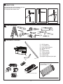
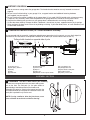
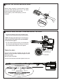
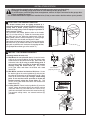
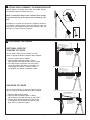
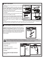
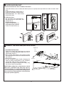
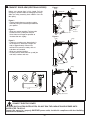
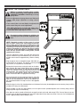
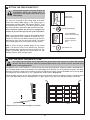
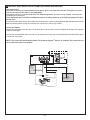
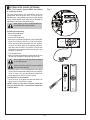
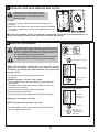
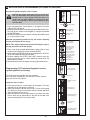
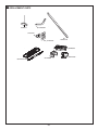
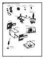
www.chamberlainanz.com
MT230
Sectional and Tilt Garage Door Opener
Installation and Operating Instructions
Owners Copy: Please keep these instructions for future reference
This manual contains IMPORTANT SAFETY information.
DO NOT PROCEED WITH THE INSTALLATION BEFORE READING THOROUGHLY.
N2966
START BY READING THESE IMPORTANT SAFETY INSTRUCTIONS
WARNING
• Failure to comply with the following instructions may result in serious personal injury or property damage.
• Read and follow all instructions carefully.
• The garage door opener is designed and tested to offer safe service provided it is installed and
operated in strict accordance with the instructions in this manual.
These safety alert symbols mean WARNING : A possible risk to personal safety or
property damage exists.
Keep garage door balanced. Do not let the
garage door opener compensate for a binding or
sticking garage door. Sticking, binding or unbalanced doors must be repaired before installing this
opener.
Do not wear rings, watches or loose clothing
while installing or servicing a garage door opener.
Frequently examine the door installation, in
particular cable, springs and mountings for signs
of wear, damage or imbalance. Do not use if repair
or adjustment is needed since springs and hardware are under extreme tension and a fault can
cause serious personal injury.
To avoid serious personal injury from entanglement, remove all ropes, chains and locks connected to the garage door before installing the
door opener.
Installation and wiring must be in compliance
with your local building and electrical codes.
The safety reverse system test is very important. Your garage door MUST reverse on contact
with a 40mm obstacle placed on the floor. Failure
to properly adjust the opener may result in serious
personal injury from a closing garage door.
Repeat the test once a month and make any
necessary adjustments.
This opener should not be installed in a damp
or wet space exposed to weather.
This appliance is not intended for use by persons
(including children) with reduced physical, sensory
or mental capabilities, or lack of experience and
knowledge, unless they have been given supervision or instruction concerning use of the appliance
by a person responsible for their safety.
The Protector SystemTM must be used for all
installations where the closing force as
measured on the bottom of the door is over
400N (40kgf). Excessive force will interfere
with the proper operation of the Safety
Reverse System or damage the garage door.
After installation, ensure that the parts of
the door do not extend over public footpaths or roads.
Install the wireless wall control (or any additional wall control) in a location where the
garage door is visible, at a height of at least
1.5m and out of the reach of children. Do
not allow children to operate push button(s)
or transmitter(s). Serious personal injury from
a closing garage door may result from misuse
of the opener.
Permanently fasten the Warning Labels in
Prominent Places, adjacent to Wall Controls
and manual release mechanisms as a
reminder of safe operating procedures.
Activate opener only when the door is in
full view, free of obstructions and the opener is properly adjusted. No one should
enter or leave the garage while the door is
in motion.
Do not allow children to play near the door,
or door controls.
Disconnect electric power to the garage
door opener before making repairs or
removing covers.
KEEP THESE INSTRUCTIONS
Warning: If your garage has no service entrance door, a CM1702 outside quick release must be installed.
This accessory allows manual operation of the garage door from outside in case of power failure.
CONTENTS
PAGE
SAFETY INSTRUCTIONS . . . . . . . .2
DOOR TYPES . . . . . . . . . . . . . . . . .3
TOOLS REQUIRED . . . . . . . . . . . .3
HARDWARE PROVIDED . . . . . . . .3
BEFORE YOU BEGIN . . . . . . . . . . .4
COMPLETED INSTALLATION . . . .4
ASSEMBLY . . . . . . . . . . . . . . . . .4-5
INSTALLATION . . . . . . . . . . . . .6-10
ADJUSTMENT . . . . . . . . . . . . .11-12
SAFETY REVERSE SYSTEM . . . .12
INSTALL IR SAFETY BEAMS . . . .13
2
AUTO-CLOSE . . . . . . . . . . . . . . . .14
WIRED DOOR CONTROLS . . . . .15
WIRELESS PROGRAMMING .15-16
ACCESSORIES . . . . . . . . . . . . . . .17
REPLACEMENT PARTS . . . . .18-19
DIAGNOSTIC CHART . . . . . . . . .20
TROUBLESHOOTING . . . . . . . . . 21
SPECIFICATIONS . . . . . . . . . . . .22
OPERATION OF YOUR OPENER 22
MAINTAINING YOUR OPENER . .22
CARE OF YOUR OPENER . . . . . .22
WARRANTY . . . . . . . . . . . . . . . . .23
1
DOOR TYPES
A. One-piece door with horizontal track only
B. Sectional door with curved track
A
C. One-piece door without track
2
TOOLS REQUIRED
1
3
C
B
2
HARDWARE PROVIDED
1
4
2
6
7
9
8
MT230 opener
Curved door arm
Door mounting bracket
Straight door arm
Idler
Header bracket
Trolley assembly
Chain and joiner
Hardware bag
Optional Segmented pole pack
7527SP1 (optional accessory)
2.75m Segmented pole pack
(separate carton)
3
5
(1)
(2)
(3)
(4)
(5)
(6)
(7)
(8)
(9)
(10)
3m Chain Pack and Joiner
3
10
4
BEFORE YOU BEGIN
5
COMPLETED INSTALLATION (TILT DOOR EXAMPLE SHOWN)
1. Look at the wall or ceiling above the garage door. The header bracket must be securely fastened to structural
supports.
2. Do you have a finished ceiling in your garage? If so, a support bracket and additional fastening hardware
(not supplied) may be required.
3. Do you have an access door in addition to the garage door? If not, model CM1702 outside quick release accessory
is required. This accessory allows manual operation of the garage door from outside in case of power failure.
4. Complete the following test to make sure your garage door is balanced and is not sticking or binding:
• Lift the door about halfway. Release the door. If balanced, it should stay in place, supported entirely by its springs.
• Raise and lower the door to see if there is any binding or sticking. If your door binds, sticks, or is out of balance, call
a trained door technician.
As you proceed with the assembly, installation and adjustment procedures in this manual, you may find it helpful to
refer back to this illustration of a completed installation for tilt doors (for sectional doors refer section 17).
Trolley shuttle located on opposite side of pole
1
3
2
14
13
4
5
9
DOOR
15
10
(1)
(2)
(3)
(4)
(5)
6
Header sleeve
Idler pulley bracket
Trolley
Pole
Chain/belt
7
8
11
12
6
NOT
ICE
(6) Hanging bracket
(7) Power cord
(8) Opener
(9) Light lens
(10) Manual release rope & handle
ASSEMBLY SECTION
ASSEMBLE 7527SP1 POLE PACK (OPTIONAL)
Remove the 5 sectional poles from the carton and lay them
out on the floor. The end pole (i.e. the pole without a
tapered edge) should be placed at the header end.
Assemble the poles by inserting the tapered end into the
non-tapered end of the next pole as illustrated. Ensure that
each pole is pushed firmly into the next.
NOTE: If using a mallet to drive the joins home, use a
piece of timber at each end to minimise burring.
4
(11) Curved door arm
(12) Straight door arm
(13) Door bracket and plate
(14) Header bracket
(15) Trolley release arm
7
INSTALL THE TROLLEY AND IDLER PULLEY
2
Slide the trolley assembly (1) onto the pole (3) taking
note of the door direction arrow (fig 1). The trolley
should be located midway along the pole.
Insert the pole (3) into the idler pulley (2) end as
illustrated.
1
DO
Fig. 1
8
3
OR
132
A2
605
-1
REMOVE CHAIN SPROCKET COVER AND INSTALL THE CHAIN
• Remove the sprocket cover from the opener and
wrap the chain around the desired chain sprocket.
NOTE: The large sprocket may be used for door
types A and B, the smaller drive sprocket MUST
be used for door type C.
• Run the chain through the trolley as illustrated and
join using the chain connector. Ensure the connector is located 300 to 500mm from the opener.
Tighten the chain:
15 Tooth Sprocket
for doors 2.5 to 3m or one
piece doors without track
Once the chain has been installed, join the two ends
together using the connector. Rotate the adjuster until the
chain has no slack.
DO NOT OVER TIGHTEN!
20 Tooth Sprocket
for sectional doors
Once the chain has been tensioned, tighten the lock nuts.
Connecting the chain
300-500mm
Lock nut
Rotate adjuster
Lock nut
NOTE: Trolley shuttle located on
opposite side of pole
5
INSTALLATION SECTION
Wear protective goggles when working overhead to protect your eyes from injury.
Disengage all existing garage door locks to avoid damage to the garage door.
To avoid serious personal injury from entanglement, remove all ropes connected to the garage door
before installing the opener.
It is recommended that the opener be installed 2.1m (7 feet) or more above the floor where space permits.
9
POSITION THE HEADER BRACKET
The header bracket must be rigidly fastened to a
structural support of the garage. Reinforce the wall or
ceiling with a 40mm (1-1/2") board if necessary.
Failure to comply may result in improper operation of
safety reverse system.
You can attach the header bracket either to the header
wall (1) or to the ceiling (3). Follow the instructions which
will work best for your particular requirements. With the
door closed, mark the vertical centreline (2) of the garage
door. Extend line onto header wall above the door.
Open door to highest point of travel. Draw an intersecting
horizontal line (4) on header wall 50mm or 200mm above
high point to provide travel clearance for top edge of door,
(height depends on door type refer section 15).
10
INSTALL THE HEADER BRACKET
1
4
2
3
4
Installing Header Bracket Pole
A. Wall Mount for one piece tilt doors: Centre the bracket (2) on the vertical guideline (1) with the bottom edge
of the bracket on the horizontal line (6). Mark either set
of bracket holes (4) if using a central fixing point. If
not use the screws provided to fasten the bracket
securely using the corner holes (5). Drill 4.5mm
(3/16") pilot holes and fasten the bracket with wood
screws (3).
B. Wall Mount sectional and tracked tilt doors: Centre
the bracket (2) on the vertical guideline (1) with the bottom edge of the bracket on the horizontal line (6). Mark
either set of bracket holes (4) if using a central fixing
point. If not use the screws provided to fasten the
bracket securely using the corner holes (5). Drill
4.5mm (3/16") pilot holes and fasten the bracket with
wood screws (3).
C. Ceiling Mount: Extend vertical guideline (1) onto the
ceiling. Centre the bracket (2) on the vertical mark no
more than 150mm (6") from the wall. Drill 4.5mm (3/16")
pilot holes and fasten the bracket with wood screws (3).
For concrete ceiling mount, use concrete anchors (7)
provided.
6
1
A
2
6
1
5
200mm
50mm to 200mm
(depending on door type)
B
50mm
3
7
C
2
150mm
(6")
6
3
2
1
3
3
11
ATTACH POLE ASSEMBLY TO HEADER BRACKET
Position opener on garage floor below the header bracket.
Use packing material to protect the cover.
2
NOTE: To enable the Pole to clear sectional door springs,
it may be necessary to lift opener onto a temporary support.
1
The opener must either be secured to a support or held firmly in place by another person. Raise the pole assembly until
chain pulley and header brackets come together. Join with
clevis pin (1). Insert R-Clip (2) to secure.
1
2
12
POSITIONING THE OPENER
Header 50mm (2”)
Bracket above the highest
SECTIONAL DOOR OR
TRACKED TILT DOOR
Pole
point of travel
You will need a 50mm piece of timber or similar
spacer to gauge the distance between door and pole.
Door
1. Raise the opener onto a support.
2. Open the door completely, place a 50mm
spacer between the door and the rail (as shown).
3. If the top section or panel hits the trolley when
you raise the door, pull down on the trolley arm
to disengage the opener. Leave the trolley in
this position until opener is fastened in place.
50mm spacer should
be used to determine
the correct mounting
from the ceiling
Header 50mm (2”)
Bracket above the highest
Pole
point of travel
Door
50mm spacer should
be used to determine
the correct mounting
from the ceiling
ONE PIECE TILT DOOR
You will need a 100mm (4”) piece of timber or similar
spacer to gauge the distance between door and pole.
1. Raise the door onto a support.
2. Open the door completely, place a 100mm
spacer between the door and the rail (as shown).
3. The top of the door should be level with the top
of the opener. Do not position the opener more
than 50mm (2”) above this point.
200mm (8”)
Header above the highest Pole
Bracket point of travel
Top of Door
100mm spacer should
be used to determine
the correct mounting
from the ceiling
7
13
HANG THE OPENER
14
ATTACH MANUAL RELEASE ROPE & HANDLE
The opener must be securely fastened to a structural support A
B
2
2
of the garage.
4
2
3
Three representative installations are shown. Yours may be
1
3
different. Hanging brackets (1) should be angled (Figure A)
3
to provide rigid support. On finished ceilings, (Figure B)
6
2
1
attach a sturdy metal bracket (not supplied) (4) to a structur6
al support before installing the opener.
For concrete ceiling mount, (Figure C), use concrete anchors
(5) (provided).
2
C
5
On each side of opener measure the distance from the open1
er to the structural support (or ceiling).
3
2
3
Cut both pieces of the hanging bracket to required lengths.
Flatten one end of each bracket and bend or twist to fit the
6
fastening angles. Do not bend at the bracket holes. Drill 4, 5
5mm (3/16") pilot holes in the structural supports (or ceiling).
Attach flattened ends of brackets to supports with wood
screws (2).
Lift opener and fasten to hanging brackets with screw, lock washer. Check to make sure the pole is centred over the
door. REMOVE 50mm board. Operate door manually. If door hits the pole, raise header bracket.
Thread one end of rope (1) through hole in top of red handle so
"NOTICE" reads right side up as shown (3). Secure with an overhand knot (2). Knot should be at least 25mm (1") from end of the
rope to prevent slipping. Thread other end of rope through hole in
release arm of the outer trolley (4). Adjust rope length so that handle is 1.8m (6 feet) above the floor. Secure with an overhand knot.
Note: If it is necessary to cut rope, heat seal cut end to
prevent fraying.
DOOR
2
4
1
NOT
ICE
3
2
DO NOT DISENGAGE THE OPENER TO MANUAL OPERATION WITH CHILDREN, PERSONS OR OTHER
OBJECTS INCLUDING MOTOR VEHICLES WITHIN THE DOORWAY: (The door is under significant tension and if
the door has developed a fault or incorrect tension, it may be unsafe and may fall rapidly.)
Door should be released in the closed
position if possible.
To Disengage:
Pull down the on red handle.
DOOR
DO NOT USE THE HANDLE TO OPEN OR
CLOSE THE DOOR.
DOOR
Engaged
Disengaged
To Engage:
Pull the red handle up and back towards the
opener. The trolley will engage when opener
is activated.
8
15
FASTEN DOOR BRACKET
Sectional and One-Piece Door Installation Procedure:
1. Centre door bracket (with or without door bracket plate, as required) at the top inside face of door as shown. Mark
holes.
A. One-piece doors: locate bracket at
inside face of the door 0-100mm down.
B. Sectional door: 150 - 250mm below
the top of the door.
2. A. Wooden doors
Drill 8mm holes (5/16") and fasten the
door bracket with nut, lock washer, and
carriage bolt (3).
B. Sheet metal doors
Fasten with wood screws (2).
C. One-piece door optional
Fasten with wood screws (2).
3
A. 0-100mm
B. 150-250mm
2
3
1
B
A
C
1
3
1
2
2
1
16
CONNECT THE DOOR ARM (ONE PIECE DOORS)
Figure 4
Assemble the Door Arm:
• Fasten the straight and curved door arm sections
together to the longest possible length with a 2 or 3
hole overlap (Figure 4).
• Make sure the garage door is fully closed. Connect
the straight door arm section to the door bracket with
the clevis pin.
• Secure with an R-clip.
• Pull the emergency release handle, disengage the
trolley by pulling straight down on the emergency
release cord. Slide the trolley toward opener.
• Connect the curved arm section to the trolley using
the clevis pin and R-clip provided.
Door
Bracket
R-Clip
Lock
Washers
Nuts
Straight
Arm
Clevis Pin
Curved
Door Arm
Figure 5
Trolley
NOTE: When setting the up limit the door should
NOT have a backward slant when fully open as
illustrated (Figure 5). A slight backward slant will
cause unnecessary bucking and/or jerking operation as the door is being opened or closed from the
fully open position (figure 5).
Correct Angle
Open Door
9
Door with
Backward Slant
(Incorrect)
17
CONNECT DOOR ARM (SECTIONAL DOORS)
Figure 1
Trolley
Pulley
Makes sure garage door is fully closed. Pull the
emergency release handle to disengage the trolley.
Slide the trolley assembly back 200mm from the
idler pulley.
200mm (8”) min.
Figure 1.
• Fasten straight door arm section to trolley
assembly using the hardware provided with
your opener.
R-clip
Fastener
Clevis Pin
2
Figure 2.
• Bring arm section together. Find two pairs
of holes that line up and join sections.
Select holes as far apart as possible to
increase door arm rigidity.
Emergency
Release
Handle
Door
Bracket
Straight
Door Arm
Curved Door Arm
1
Figure 2
Figure 3.
• If holes in curved arm are above holes in
the straight arm, disconnect straight arm
and cut approximately 150mm from
solid end. Re-connect to trolley with cut
end down as illustrated.
• Bring arm sections together.
• Find two pairs of holes that line up and join
with bolts, washers and nuts.
Trolley
Pulley
200mm (8”) min.
4
5
3
Door Bracket
Figure 3
Trolley
Pulley
200mm (8”) min.
HARDWARE PROVIDED
5
4
2
1
5
4
3
3
Cut this end
CONNECT ELECTRIC POWER
TO AVOID INSTALLATION DIFFICULTIES, DO NOT RUN THE GARAGE DOOR OPENER UNTIL
INSTRUCTED TO DO SO.
Connect the opener to a properly EARTHED power outlet, installed in compliance with local building
and electrical standards.
10
18
ADJUST THE TRAVEL LIMITS
ADJUSTMENT SECTION
Without a properly installed safety system,
persons (particularly small children) could be
SERIOUSLY INJURED or KILLED by a closing
garage door.
• Incorrect adjustment of garage door travel limits will
interfere with proper operation of safety reversal
system.
• If one control (force or travel limits) is adjusted, the
other control may also need adjustment.
• After ANY adjustments are made, the safety reversal system MUST be tested. Door MUST reverse on
contact with 40mm high object on floor.
To prevent serious damage to vehicles, be
sure fully open door provides adequate clearance
NOTE: Repeated operation of the opener in a short
period of time during setup may trigger the thermalcutout of the motor. In this case you will have to wait
for approximately five minutes for the motor to cool
sufficiently to continue the installation process. If the
unit has overheated you will hear the relays clicking
in response to the transmitter or pushbutton but the
motor will not operate. After cooling down, normal
operation will resume.
The limit adjustment screws are inside the lamp cover
and are marked as up limit and down limit. One full turn
of either screw results in approximately 150mm of trolley
travel.
DOWN
LIMIT
UP
LIMIT
• Remove the lamp cover by turning the catch on its underside. Remove the green control panel cover to expose
the setup controls. Observe the red and orange indicator
LEDs. The red LED will stay on continuously at the fully
closed position. The orange LED will stay on continuously at the fully open position. Identify the green operate
button. Ensure the door is engaged on the trolley.
arrow = more travel
• Plug the opener into an earthed three-pin 220-240V outlet and switch on the power. The opener’s courtesy lamp
may turn on, or may flash for five seconds.
• Press and release the green operate button to move the
door up or down. Press again to stop in the required fully
open or fully closed positions. Each time the operate button is pressed the door will stop or move in the opposite
direction.
• When the door is at the fully closed position turn the down-limit screw (located adjacent to the courtesy lamp) until the
red down-LED stays on continuously.
• When the door is at the fully open position, turn the up-limit screw (located adjacent to the courtesy lamp) until the
orange up-LED stays on continuously.
• If the door can not be moved sufficiently far enough then look at the red and orange LEDs. If one of these is on continuously then the door has stopped at a limit point. Adjust that limit to allow more travel. One turn of a limit adjustment
screw = approximately 250mm of door travel.
11
19
SETTING THE FORCE SENSITIVITY
The Protector SystemTM must be used for all
installations where the closing force as
measured on the bottom of the door is over
400N (40kgf).
The force, as measured on the closing edge of the door,
should not exceed 400N (40kgf). If the closing force is
measured to more than 400N, The Protector SystemTM must
be installed (refer section 21). The force setting regulates
the amount of power required to open and close the door.
This procedure requires the door to be engaged (see
section 14) and run through one full cycle of operation.
Step 1: Start with the door in the fully open position and the
green control panel cover should be removed (see fig 1
section 22). Press the red “learn” button twice on the control panel to enter into the force learn mode. The amber
LED marked open on the control panel will flash quickly.
Step 2: Press the green operate button on the control
panel. The door will travel to the DOWN limit. Press the
operate button again, the door will travel to the UP limit. The
amber LED marked open on the control panel will stop
flashing when the force has been learnt.
20
operate
Press learn
button twice
learn
x2
close
open
operate
learn
open
LED will start flashing
Press OPERATE
button (door will close)
Press OPERATE
button to open the
door
LED will turn off
TEST THE SAFETY REVERSE SYSTEM
The safety reverse system test is important. The garage door must reverse on contact with a 40mm
obstacle laid flat on the floor. Failure to properly adjust opener may result in serious personal injury
from a closing garage door.
Procedure: Place a 40mm obstacle (1) laid flat on the floor under the garage door. Operate the door in the down direction. The door must reverse on the obstacle. If the door stops on the obstacle, it is not travelling far enough in the down
direction. Remove the lamp cover to locate the travel limit adjustment screws. Increase the down limit by turning down
limit adjustment screw clockwise (1 turn = approximatly 250mm travel). Repeat test.
When the door reverses on the 40mm obstacle, remove the obstacle and run the opener through a complete travel
cycle. Door must not reverse in closed position. If it does, adjust Limits and Force and repeat safety reverse test.
40mm
1
40mm
Repeat test once a month and adjust as needed.
12
1
21
INSTALL THE PROTECTOR SYSTEMTM (OPTIONAL ACCESSORY)
(See accessories)
Install this accessory for all installations on tilt doors, doors over 2.5m and when the closing force as measured on the bottom of the door is over 400N (40kg).
After opener has been installed and adjusted, The Protector System™ accessory can be installed. Instructions are
included with this accessory.
The Protector System™ provides an additional measure of safety against a small child being trapped under a
garage door.
It uses an invisible beam which, when broken by an obstruction, causes a closing door to open and prevents an open
door from closing and is strongly recommended for homeowners with young children.
manual control
manual control
2
3
1
Connection details:
Connect the two white wires from the C77 IR safety beams to the white 2 terminal located2 on 3the 1back of
the opener
771ANZ
under the cover plate.
12Vdc
+
roller:R
roller:R
com
IR
P/B
12Vdc
+
L
L
IR
com
P/B
Connect the two white/black wires from the C77 IR safety beams to the grey 3 terminal located on the back of the opener under the cover plate.
P/B
open
timer
to
close
NOTE: The opener will automatically detect The Protector SystemTM when it is installed. The opener will not
close unless the sensors are aligned.
operate
close
132A2663
learn
manual control
12Vdc
+
2
com
3
IR
red
white
1
P/B
External
Device
100ma (max)
12vdc
gnd
rx
white
white/ black
white
white/ black
13
no
com
Keyswitch or
push button
SETTING AUTO CLOSE (OPTIONAL)
Fig. 1
learn
close
0s/off
60s
open
180s
timer to
close
R
R
roller:L
roller:L
DOWN
LIMIT
arrow = more travel
UP
LIMIT
Auto close is NOT recommended for
households with young children.
operate
NOTE: The Protector SystemTM MUST be installed
to enable this feature.
The auto close feature will automatically close the
garage door after the preset time. The time can be
adjusted up to 180 seconds using the trim pot located
on the control board. Auto close can be disabled by
adjusting the trim pot to the 0s/off setting.
132A2663
22
Installing and adjusting:
• Close the garage door.
• Turn the opener off.
• Remove the lamp cover.
• Ensure the trim pot on the opener is set to the 0s/off.
• Install The Protector SystemTM using the brackets,
wires and instructions provided with the product.
Twist the two white (only) wires together and terminate them into the white (2) terminal. Twist the two
white/black wires together and terminate them into
the grey (3) terminal.
• Turn the opener on.
• Allow 5 minutes for the beams to self-learn to the unit
(do not walk through the beam during this time).
manual control
12Vdc
+
2
com
3
IR
1
P/B
Do not adjust the trim pot whilst the door is
in the open position.
Door will activate when the trim pot is adjusted in the open position
roller:L
roller:L
• Ensure the door is in the closed position, then adjust
the trim pot to the desired closing time by turning the
“timer to close” trim pot anti-clockwise (label indicates approximate Timer To Close values).
Test the timer to close feature:
• Once the timer is set open the door and allow it to
close via the “timer to close” feature.
NOTE: If more or less time is desired, adjust the
trim pot whilst the door is closed then repeat test
outlined above.
remove
for setup
R
R
open
180s
timer to
close
operate
60s
0s/off
close
132A2663
learn
manual
control
14
23 INSTALLING YOUR CM128 WIRELESS WALL BUTTON
Disconnect power to the opener whilst
installing this accessory to prevent accidental activation. Locate minimum 1.5m
above the floor.
To install:
+
• Carefully pry open the CM128 and locate the two screws for
mounting.
• Attach to the wall using the two screws and wall anchors provided
if mounting to a plaster wall. If using a recessed wall box do not
use anchors.
+
+
NOTE: Do not overtighten screws. The wall button supplied with your opener is pre-programmed to your
opener in the factory. If adding a new wall button, follow the steps below.
24 WIRELESS PROGRAMMING
Activate the opener only when door is in full view, free of
obstruction and properly adjusted. No one should enter
or leave garage whilst door is in motion. Do not allow
children to operate push button(s) or transmitter(s). Do
not allow children to play near the door.
Fix any wall control at a height of at least 1.5m and within sight of the door but away from any moving parts.
NOTE: The transmitters supplied with your opener are pre-programmed to your opener in the factory. If you purchase additional
transmitters, you will need to program them into your opener using
the steps below.
• Fix the warning against entrapment label near the
wall control.
ADDING transmitters using the “learn” button
• Press and hold down the transmitter button you wish to program
to the opener.
• The orange LED will flash continuously to indicate it is receiving
signal from the transmitter.
• Press and release the “learn” button on the opener.
• The courtesy light will flash once.
• Ensure the door is clear of obstruction, then test the transmitter.
Deleting ALL transmitters and codes
NOTE: This deletes all transmitters and codes.
TO ADD Transmitters / Wall Control
or
Press and hold down the desired
button.
open
LED will flash continuously
operate
learn
Press and release
the red learn button
close
Courtesy light will
flash once
TO DELETE ALL TRANSMITTERS
operate
learn
Press and
hold the red
learn button
close
• Press and hold the “learn” button until the orange indicator light
goes out (approximately 9 sec).
15
open
LED will light up
open
LED will go out
after (approx) 9
seconds. Release
learn button
25 KEYLESS DEVICE PROGRAMMING (OPTIONAL ACCESSORY)
Programming C840 using the “learn” button:
Activate the opener only when door is in full view,
free of obstruction and properly adjusted. No one
should enter or leave garage while the door is in
motion. Do not allow children to operate push button(s) or transmitter(s). Do not allow children to play
near the door.
1. Press and release the “learn” button (1) on opener. The learn
indicator LED will light up.
2. Within 30 seconds, enter a four digit personal identification number (PIN) of your choice on the keypad (2), then press and hold
the ENTER button.
3. Release the button when the opener courtesy light flashes once
(3). It has learnt the code.
Alternate programming method using the motion detecting
control panel (optional accessory):
NOTE: This method requires two people if the keyless entry is
already mounted outside the garage.
1. Enter a four digit personal identification number (PIN) of your
choice on the keypad, then press and hold ENTER.
2. While holding the ENTER button, press and hold the LIGHT button on the motion detecting control panel.
3. Continue holding the ENTER and LIGHT buttons while you
press the push bar on the motion detecting control panel (all
three buttons are held).
4. Release buttons when the opener courtesy light flashes once.
1
operate
close
open
Using the “learn” button:
LED will light up
2
Enter 4 digit PIN at
keypad (within 30s)
3
Courtesy light will
flash once
1
Enter 4 digit PIN at
keypad (within 30s)
2
Press and hold down
LIGHT button on the
motion detecting
control panel
LIGHT
LOCK
3
With the LIGHT button
pressed, press and
hold the PUSH BAR on
the motion detecting
control panel
LOCK
LIGHT
4
Release buttons
when light flashes
Programming C379 wireless fingerprint access
system (optional accessory)
Full instructions are available with this accessory.
Once you have enrolled your user into the C379 you can program the unit into your opener.
Press and release
the red learn button
learn
operate
learn
Press and release
the red learn button
close
open
LED will light up
A
ENROLL
1. Press and release the “learn” button on the opener. The learn
indicator LED on the opener will light up.
2. Within 30 seconds, slide the cover of the C379 up as illustrated
(A). Swipe your finger on the reader head at a steady speed (B)
until the yellow led turns on (C).
3. When the opener’s courtesy light flashes it has learnt the code.
Ensure there are no obstructions in the path of the door, then
press the send button (D) to test the door.
SEND
ENROLL
PASS
FAIL
READY
RETRY
Slide the cover plate
up (A)
B
Swipe finger at a
steady speed (B)
C
ENROLL
SEND
ENROLL
PASS
FAIL
READY
RETRY
Yellow LED will indicate
successful swipe (C)
Courtesy light will
flash once
D
Test reader by pressing
the send button (D)
16
26
INSTALL OR REPLACE THE LAMP
• Remove power from the opener before adding or
replacing the light bulb. Use only E27 45mm
Round 40W max light bulbs.
• Remove lamp cover (if installed). Push in slightly
and turn to release the screw with a large screwdriver or coin. Carefully remove the cover and put
in a safe place.
• Add or replace the lamp as illustrated.
• Replace the cover and fasten in place by turning
the release screw to the closed position.
27
ACCESSORIES
(1) Model CM844
(2) Model CM128
(3) Model C940
(4) Model C943
(5) Model C945
(6) Model 75LM
4 Channel transmitter
Wireless wall button
Single channel transmitter
3 Channel transmitter
3 Channel mini transmitter
Illuminated door bell push button
CM844
2
1
C840
9
Motion detecting control panel
Keyless entry system
The Protector SystemTM (IR Beams)
Quick release lock
Outside keyswitch
Wireless fingerprint access system
433Hz Antenna, cable and adaptor
C945
C943
3
C1702
C77
8
C940
CM128
(7) Model C98
(8) Model C840
(9) Model C77
(10) Model CM1702
(11) Model 760E
(12) Model C379
(13) Model ANT4X-1
4
6
5
11
LOCK
LIGHT
ENROLL
SEND
ENROLL
PASS
FAIL
READY
RETRY
12
17
C98
C379
760E
10
75LM
13
7
28
REPLACEMENT PARTS
NOT
ICE
178B0086B
091B0019
012B0905
012B0906
178B0034B
002A0958
001A6829
012A0932
18
001A6698
29
REPLACEMENT PARTS (CONTINUED)
PDR59003
Service logic board
CDR11520
Dual sprocket
203D1720
Motor capacitor
PDR40082
Insulated varistor
PDR50098
Motor & worm gear
assembly
BDR21043
PDR30018
Speed sensor
CDR10693
Side cover
217H 0375
Lampholder
PDR59001
Chasis complete assembly
ADR12392
Main cover V2
CDR10693
Side cover
PDR50070
Light cover
041A2828
Handle & pull
rope assembly
19
DIAGNOSTIC CHART
1 FLASH
Safety reversing sensors
wire open (broken or disconnected).
OR
2 FLASHES
Safety reversing sensors
wire shorted or black/white
wire reversed.
3 FLASHES
Door control or
wire shorted.
4 FLASHES
Safety reversing sensors
slightly misaligned
(dim or flashing LED).
5 FLASHES
Possible RPM sensor
failure. Unplug to reset.
6 FLASHES
Possible limit switch
error on start up.
10 to 15 FLASHES
System failure
Symptom: One or both of the indicator lights on the IR Beams are not on
steadily.
• Inspect sensor wires for an electrical short (eg. staple in wire), correct wiring polarity (black/white wires reversed), broken or disconnected wires, replace/attach as
needed.
• Disconnect all wires from the opener.
• Remove beams from brackets and shorten sensor wires to 30-60mm (1-2”) from
back of each sensor.
• Re-attach sending eye to opener using shortened wires. If sending eye indicator
light glows steadily, attach the receiving eye.
• Align beams. If the indicator lights glow, replace the wires for the beams. If the sensor indicator lights do not light up, replace the IR Beams.
Symptom: LED is not lit on door control.
• Check polarity of the wire connection to the opener.
• Inspect door control/wires for an electrical short (eg. staple in wire), replace as needed.
• Disconnect wires at door control, touch wires together. If opener activates, replace
door control.
• If opener does not activate, disconnect door control wires from opener. Momentarily
short across red and white terminals with jumper wire. If opener activates, replace
door control wires.
Symptom: Sending indicator light glows steadily, receiving indicator light is
dim or flashing.
• Realign receiving eye sensor, clean lens and secure brackets.
Symptom: The RPM Sensor = Short travel 150-200mm (6-8").
• Unplug unit to reset. Try to operate opener. Check diagnostic code.
• If it is still flashing 5 times and opener moves 150-200mm (6-8"), the RPM sensor
may need to be replaced, for details contact your Chamberlain Merlin Professional
Dealer.
Symptom: Door will not open or close
• Turn the power off. Wait 10 seconds.
• Turn power back on. If opener fails to operate correctly after resetting, contact
your Chamberlain Merlin Professional Dealer.
Symptom: Opener will not open or close the door
• Turn the power off. Wait 10 seconds.
• Turn power back on. If opener fails to operate correctly after resetting, contact your
Chamberlain Merlin Professional Dealer.
(report the number of flashes as the fault reference).
20
TROUBLESHOOTING
1. The opener doesn't operate from either the
START/STOP button or the transmitter:
• Does the opener have electric power? Plug a lamp into the outlet. If it doesn't light, check the fuse box.
• Have you disabled all door locks? Review installation instruction warnings on page 2.
• Is there a build-up of ice or snow under the door? The door may
be frozen to the ground. Remove any restriction.
• The garage door spring may be broken. Have it replaced.
2. Opener operates from the transmitter, but not
from the wired wall control (optional accessory):
• Is the wall control lit? If not, reverse the two wires. If the opener runs, check for a faulty wire connection at the wall control, a
short under the staples, or a broken wire.
• Are the wiring connections correct? Refer to wired wall control
instructions.
3. The door operates from the START/STOP button or
wired wall control, but not from the wireless wall
control or transmitter:
• If the wired wall control is installed and it is flashing, ensure the
lock feature is off.
• Program the opener to match the transmitter code. (Refer to
section 24). Repeat with all transmitters.
4. The transmitter has short range:
• Change the location of the transmitter in your car.
• Check to be sure the antenna on the bottom of the opener
extends fully downward.
• Some installations may have shorter range due to a metal door,
foil backed insulation, or metal garage siding.
• Replace transmitter batteries.
5. The garage door opens and closes by itself:
• Be sure that all transmitter push buttons are off.
• If the wired wall control (optional accessory) is installed, remove
the bell wire from the wired wall control terminals and operate
from the START/STOP button or transmitter. If this solves the
problem, the wired wall control is faulty (replace), or there is an
intermittent short on the wire between the wired wall control
and the opener.
• Clear memory and re-program all wireless wall controls and
transmitters.
6. The door will stop, reverses slightly away from the
obstruction then stop:
• Is something obstructing the door? Is it out of balance, or are
the springs broken? Remove the obstruction or repair the door.
7. The door reverses for no apparent reason and
opener light flashes for 5 seconds after reversing:
• Check The Protector SystemTM (IR Beams), if installed Correct
alignment if the red light on the beam is solid.
21
8. The door opens but won't close or reverses while
closing:
• Is something obstructing the door? Pull the manual
release handle. Operate the door manually. If it is unbalanced or binding, call a trained door systems technician.
• Clear any ice or snow from the garage floor area where
the door closes.
• Repeat the limit and force setting in section 18 and section 19.
Repeat safety reverse test after adjustments.
9. The opener strains to operate door:
• The door may be out of balance or the springs may be
broken. Close the door and use the manual release to disconnect the door. Open and close the door manually. A
properly balanced door will stay in any point of travel
while being supported entirely by its springs. If it does not,
disconnect the opener and call a trained door systems
technician.
10. The opener hums briefly, then won't work:
• Check that the door is not in manual release mode, refer
section 14.
• The garage door springs may be broken. See above.
• If the problem occurs on the first operation of the opener,
door may be locked. Disable any door locks.
11. The opener won't operate due to power failure:
• Use the manual release handle to disconnect the door. The door
can be opened and closed manually. When power is restored, reengage the opener, refer section 14.
12. The opener flashes once every minute for 10
minutes after operating (optional feature):
• Door and opener requires service. Contact your local
Chamberlain Merlin dealer.
OPERATION OF YOUR OPENER
CARE OF YOUR OPENER
Your opener can be activated by any of the following
devices:
When properly installed, your opener will operate with
minimal maintenance. The opener does not require additional lubrication.
• The START/STOP button
Press the button until door starts to move.
Limit and force settings: These settings must be checked
and properly set when the opener is installed. Weather
conditions may cause some minor changes in the door
operation, requiring some re-adjustments, particularly
during the first year of operation. Refer to limit and force
setting in, sections 18 & 19.
• The wall control, outside keylock or keyless
entry system (if you have installed any of these
accessories).
Follow the instructions carefully and repeat the safety reverse test after any adjustment.
• The transmitter or wireless wall
button (CM128)
Hold the push button down until the door starts to move.
transmitter:
Additional transmitters can be purchased at any time.
Refer to accessories. Any new transmitters must be programmed into the opener.
When the opener is activated by transmitter,
START/STOP button or wall control:
transmitter battery:
• If open, the door will close. If closed, the door will open.
• If closing, the door will stop.
• If opening, the door will stop (allowing space for entry
and exit of pets and for fresh air).
• If the door has been stopped in a partially open or
closed position, it will reverse direction.
• If an obstruction is encountered while closing, the door
will stop, then reverse.
• If an obstruction is encountered while opening, the door
will stop, reverse away from the obstruction then stop.
• The optional Protector System™ uses an invisible beam
which, when broken by an obstruction, causes a closing
door to open and prevents an open door from closing. It
is STRONGLY RECOMMENDED for homeowners with
young children.
If transmission range decreases, replace the battery.
MAINTENANCE OF YOUR OPENER
Once a month:
• Repeat safety reverse test.
Make any necessary adjustments (sections 18 & 19)
• Manually operate door. If it is unbalanced or binding,
call for professional garage door service.
• Check to be sure door opens and closes fully.
Set limits and/or force if necessary.
Allow a 15 minute cooling period after 4 minutes of
continuous operation of the opener.
SPECIFICATIONS MT230
Door should be fully closed if possible.
Weak or broken springs could allow an
open door to fall rapidly. Property damage
or serious personal injury could result.
Input Voltage:
230-240VAC, 50Hz, 460W
Max.Pull Force:
700N
Rated Load:
Opening the door manually: (refer section 14)
Max. Door Mass:
The door can be opened manually by pulling the release
cord down firmly.
To re-connect the door, push the red clutch lever up to the
top stop position.
130kg (spring balanced)
Idle Current:
less than 5mA @ 230VAC
Memory Registers:
64
Drive:
Operating Frequency:
The opener light will turn on:
• when the opener is initially plugged in;
• after the power has been briefly interrupted;
• when the opener is activated.
(the light turns off automatically after 2-1/2 minutes.)
50Nm
Auxillary power output:
AC gearmotor
433.92MHz AM Peak Detect
rolling code.
12VDC 100ma (max)
SPECIAL NOTE: Chamberlain strongly recommends that the Protector SystemTM be installed on all garage door openers.
22
CHAMBERLAIN 2 YEAR LIMITED WARRANTY
Merlin MT230
Garage Door Opener
Liability – Australia only
Under no circumstances shall the Seller be liable for consequential, incidental or special damages arising in connection
with the use, or inability to use, the Unit. In no event shall the
Seller's liability for damages or injury arising from breach of
law or contract or for negligence, exceed the cost of repairing
or replacing the Unit or refunding the purchase price of the
Unit.
Chamberlain Australia Pty Limited / Chamberlain New
Zealand Limited (Seller) warrants to the original purchaser of the Merlin MT230 Garage Door Opener (Unit) that it
is free from defects in material and/or workmanship for a
period of 2 YEARS from the date of first purchase from
the Seller. The AC motor (only) is covered by a 5 year warranty from the date of first purchase from the Seller, when
installed on a domestic door.
Under Division 2 Part V of the Trade Practices Act, 1974, certain warranties and conditions (Implied Terms) are implied
into contracts for the supply of goods or services if the goods
or services are of a kind ordinarily acquired for personal,
domestic or household use or consumption. Liability for
breach of those Implied Terms cannot be excluded or limited
and the limitations and exclusions above do not apply to the
Implied Terms.
Please retain your proof-of-purchase in the unlikely event you
require warranty service.
If, during the limited warranty period, the Unit fails due to
defects in materials or workmanship Chamberlain will, provided the defective part or Unit is returned freight and insurance
prepaid and well packaged to the nearest Chamberlain office
or authorised installer, undertake to repair or, at its option,
replace any defective part or Unit and return it to the Buyer at
no cost. Repairs and replacement parts are warranted for the
remaining portion of the original warranty period.
Except for the Implied Terms and the warranties set out
above, the Seller excludes all warranties and conditions
implied by statute, at law, in fact or otherwise.
Liability – New Zealand only
Except as set out in the Fair Trading Act 1986 and the
Consumer Guarantees Act 1993:
Limited warranty on opener
Chamberlain will furnish a replacement motor free of charge,
if it is found to be defective. Labour costs may apply.
Where the Unit has been installed by an authorised installer,
Chamberlain will furnish replacement parts free of charge
through the authorised installer. A service fee for on-site service may apply.
(a) all other guarantees, warranties and representations in
relation to the Unit or its supply are excluded to the extent
that the Seller can lawfully exclude them; and
(b) under no circumstances shall the Seller be liable for
consequential, incidental or special damages arising in
connection with the use, or inability to use, the Unit, other
than those which were reasonably foreseeable as liable
to result from the failure.
In-warranty service
During the warranty period, if the product appears as though
it may be defective, call our toll free service before removal of
the Unit. A Chamberlain technician will diagnose the problem
and promptly supply you with the parts for “do-it-yourself”
repairs, or provide you with shipping instructions for a factory
repair or replacement. If an authorised installer installed your
Unit you must call them for prompt on-site service.
NOTE: We request that you attach your sales docket or
invoice to this manual to enable you to establish the date
of purchase in the unlikely event of a service call being
made. Chamberlain reserves the right to change the
design and specification without prior notification. Some
features or accessories may not be available in certain
markets or areas. Please check with your distributor.
If our service centre determines that a warranty claim has
been made in respect of a failure or defect arising out of any
exclusion detailed below, we may charge you a fee to repair
and/or return the Unit to you.
CONTACT DETAILS:
Exclusions
This warranty does not cover any failure of the Unit due to:
1. non-compliance with the instructions regarding installation,
operation, maintenance and testing of the Unit or of any product with which the Unit is used.
2. any attempt to repair, dismantle, reinstall or move the
Product to another location once the Product is installed by
any person other than an authorised installer.
3. tampering, neglect, abuse, wear and tear, accident, electrical storm, excessive use or conditions other than normal
domestic use.
This warranty does not cover any problems with, or relating
to, the garage door or garage door hardware, including but
not limited to the door springs, door rollers, door alignment or
hinges, any problems caused by electrical faults, replacement
of batteries or light bulbs or labour charges for reinstalling a
repaired or replaced Units.
Chamberlain service centres:
Australia
Phone toll free 1800 638 234
Fax toll free 1800 888 121
New Zealand
Auckiland phone 09 477 2823
Phone toll free 0800 MERLIN
Fax toll free 0800 653 663
www.chamberlainanz.com
23
Trademark of The Chamberlain Group, Inc
® Registered Trademark of The Chamberlain Group, Inc.
TM
114A4082A
24
© 2009 The Chamberlain Group, Inc