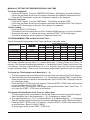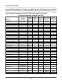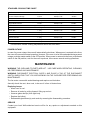
1
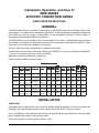
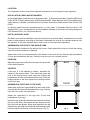
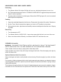
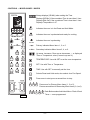
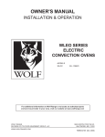
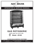
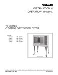
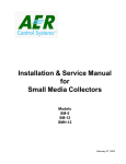
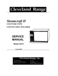
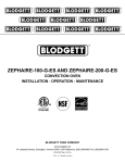
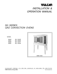
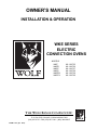
OWNER’S MANUAL
INSTALLATION & OPERATION
WKE SERIES
ELECTRIC
CONVECTION OVENS
MODELS
WKE
WKED
WKEC
WKEX
WKEDX
WKECX
ML-126755
ML-126756
ML-126757
ML-126758
ML-126759
ML-126760
THE WOLF RANGE COMPANY LLC
19600 S. Alameda St., Compton, California 90221-6291
P. O. Box 7050, Compton, California 90240-7050
(310) 637-3737 • FAX (310) 637-7931 • (800) 366-WOLF
FORM 31162 (Apr. 2000)
®
TABLE OF CONTENTS
GENERAL . . . . . . . . . . . . . . . . . . . . . . . . . . . . . . . . . . . . . . . . . . . . . . . . . . . . . . . . . . . . . . . . . . 3
INSTALLATION . . . . . . . . . . . . . . . . . . . . . . . . . . . . . . . . . . . . . . . . . . . . . . . . . . . . . . . . . . . . . .
Unpacking . . . . . . . . . . . . . . . . . . . . . . . . . . . . . . . . . . . . . . . . . . . . . . . . . . . . . . . . . . . . . .
Location . . . . . . . . . . . . . . . . . . . . . . . . . . . . . . . . . . . . . . . . . . . . . . . . . . . . . . . . . . . . . . . .
Installation Codes and Standards . . . . . . . . . . . . . . . . . . . . . . . . . . . . . . . . . . . . . . . . . . .
Installing Basic Oven . . . . . . . . . . . . . . . . . . . . . . . . . . . . . . . . . . . . . . . . . . . . . . . . . . . . .
Assembling the Legs to the Single Oven . . . . . . . . . . . . . . . . . . . . . . . . . . . . . . . . . . . . .
Leveling . . . . . . . . . . . . . . . . . . . . . . . . . . . . . . . . . . . . . . . . . . . . . . . . . . . . . . . . . . . . . . . .
Casters . . . . . . . . . . . . . . . . . . . . . . . . . . . . . . . . . . . . . . . . . . . . . . . . . . . . . . . . . . . . . . . .
Assembling the Stand to the Oven . . . . . . . . . . . . . . . . . . . . . . . . . . . . . . . . . . . . . . . . . .
Electrical Connections . . . . . . . . . . . . . . . . . . . . . . . . . . . . . . . . . . . . . . . . . . . . . . . . . . . .
Assembling Stacked Ovens . . . . . . . . . . . . . . . . . . . . . . . . . . . . . . . . . . . . . . . . . . . . . . . .
Electrical Connections (Stacked Ovens) . . . . . . . . . . . . . . . . . . . . . . . . . . . . . . . . . . . . . .
Before First Use (All Models) . . . . . . . . . . . . . . . . . . . . . . . . . . . . . . . . . . . . . . . . . . . . . . .
3
3
4
4
4
4
4
4
4
5
5
6
6
OPERATION . . . . . . . . . . . . . . . . . . . . . . . . . . . . . . . . . . . . . . . . . . . . . . . . . . . . . . . . . . . . . . . . 7
Controls — Models Models WKE / WKEX / WKED / WKEDX . . . . . . . . . . . . . . . . . . . . . 7
Using Models Models WKE / WKEX / WKED / WKEDX . . . . . . . . . . . . . . . . . . . . . . . . . 8
Cleaning (all models) . . . . . . . . . . . . . . . . . . . . . . . . . . . . . . . . . . . . . . . . . . . . . . . . . . . . . 8
Optional Stainless Steel Oven Interior . . . . . . . . . . . . . . . . . . . . . . . . . . . . . . . . . . . . . . . 8
Controls — Models WKEC / WKECX . . . . . . . . . . . . . . . . . . . . . . . . . . . . . . . . . . . . . . . . 9
Manually Setting the Temperature and Cook Time . . . . . . . . . . . . . . . . . . . . . . . . . . . . 10
To Program Menu Item and Rack # Cook Times . . . . . . . . . . . . . . . . . . . . . . . . . . . . . . 10
To Change the Time Setting for any Menu Item (1 – 6) . . . . . . . . . . . . . . . . . . . . . . . . . 10
To Program Individual Rack # Cook Times for a Menu Item . . . . . . . . . . . . . . . . . . . . . 10
Always Set the Temperature before Setting the Time . . . . . . . . . . . . . . . . . . . . . . . . . . 11
Starting a Timed Cycle on All Racks . . . . . . . . . . . . . . . . . . . . . . . . . . . . . . . . . . . . . . . . 11
Starting a Timed Cycle Using Programmed Individual Menu / Rack # Cook Time(s) . 11
To Display the Actual Oven Temperature . . . . . . . . . . . . . . . . . . . . . . . . . . . . . . . . . . . . 11
To End a Cooking Cycle. . . . . . . . . . . . . . . . . . . . . . . . . . . . . . . . . . . . . . . . . . . . . . . . . . 11
Door and Timing . . . . . . . . . . . . . . . . . . . . . . . . . . . . . . . . . . . . . . . . . . . . . . . . . . . . . . . . 11
Setting the Oven for Roast & Hold . . . . . . . . . . . . . . . . . . . . . . . . . . . . . . . . . . . . . . . . . 11
Roast and Hold Operation — Models WKEC / WKECX . . . . . . . . . . . . . . . . . . . . . . . . . 12
Proper Utensils . . . . . . . . . . . . . . . . . . . . . . . . . . . . . . . . . . . . . . . . . . . . . . . . . . . . . . . . . 12
Operating Hints . . . . . . . . . . . . . . . . . . . . . . . . . . . . . . . . . . . . . . . . . . . . . . . . . . . . . . . . . 12
Cooking Guidelines (Holding Feature) . . . . . . . . . . . . . . . . . . . . . . . . . . . . . . . . . . . . . . 13
Standard Cooking Time Chart . . . . . . . . . . . . . . . . . . . . . . . . . . . . . . . . . . . . . . . . . . . . . 14
Power Outage . . . . . . . . . . . . . . . . . . . . . . . . . . . . . . . . . . . . . . . . . . . . . . . . . . . . . . . . . . 14
MAINTENANCE . . . . . . . . . . . . . . . . . . . . . . . . . . . . . . . . . . . . . . . . . . . . . . . . . . . . . . . . . . . .
Replacing Lamps . . . . . . . . . . . . . . . . . . . . . . . . . . . . . . . . . . . . . . . . . . . . . . . . . . . . . . .
Service . . . . . . . . . . . . . . . . . . . . . . . . . . . . . . . . . . . . . . . . . . . . . . . . . . . . . . . . . . . . . . .
IMPORTANT INFORMATION . . . . . . . . . . . . . . . . . . . . . . . . . . . . . . . . . . . . . . . . . . . . . . . . .
WARRANTY . . . . . . . . . . . . . . . . . . . . . . . . . . . . . . . . . . . . . . . . . . . . . . . . . . . . . . . . . . . . . . .
© THE WOLF RANGE COMPANY LLC, 2000
–2–
14
14
14
15
16
Installation, Operation, and Care of
WKE SERIES
ELECTRIC CONVECTION OVENS
SAVE THESE INSTRUCTIONS
GENERAL
The WKE Series Electric Convection Ovens feature a 500°F thermostat, timer, porcelain interior, and
a two-speed, 1⁄2 HP blower motor as standard equipment. Ovens equipped with standard voltages are
208 or 240 Volt, 60 Hertz, single- or three-phase. Ovens equipped for 480 volt, 60 Hertz, single- or
three-phase electrical specifications are optional.
The WKE Series Oven is a single cavity oven furnished with five racks. Independently opening doors
are standard; simultaneously opening doors with chain mechanism underneath are optional. Oven
lights with on-off switch are standard on all models.
An open stand with lower storage rack is available as an option.
Stacked ovens are furnished with either Stacking Kit 426983G3 ( 8" LEGS) or Stacking Kit 426984G3
(CASTERS) for mounting one oven on top of the other.
Additional racks are available as accessories.
Features of the models are shown below:
FEATURES & OPTIONS
Model
WKE
Oven
Oven
Interior Exterior Thermostat
Depth
Depth
261/2"
411/2"
Timer
Roast 5 Hr.
& Hold Timer
Stack
Stand Stand
Stack Kit Legs Legs
Kit
with
with
with
with with
with
Rack Rack &
Casters * Feet Casters
Legs *
& Feet Casters
Mechanical 1 Hr. Dial
NA
Opt.
Opt.
Opt.
Std.
Opt.
Opt.
Opt.
"
41 /2" Solid State 1 Hr. Dial
WKED (6276.3 /c2m
) (105.4 cm)
1
24 Hr.
"
411/2"
WKEC (6276.3 /c2m
Computer
) (105.4 cm)
Digital
1
451/2" Mechanical 1 Hr. Dial
WKEX 30 /2"
NA
Opt.
Opt.
Opt.
Std.
Opt.
Opt.
Opt.
Std.
NA
Opt.
Opt.
Std.
Opt.
Opt.
Opt.
NA
Opt.
Opt.
Opt.
Std.
Opt.
Opt.
Opt.
NA
Opt.
Opt.
Opt.
Std.
Opt.
Opt.
Opt.
Std.
NA
Opt.
Opt.
Std.
Opt.
Opt.
Opt.
(67.3 cm) (105.4 cm)
1
1
(77.5 cm) (115.6 cm)
1
"
451/2" Solid State 1 Hr. Dial
WKEDX (7370.5 /c2m
) (115.6 cm)
1
24 Hr.
"
451/2"
WKECX (7370.5 /c2m
Computer
) (115.6 cm)
Digital
* With Two Stacked Ovens Only.
INSTALLATION
UNPACKING
Immediately after unpacking the oven, check for possible shipping damage. If the oven is found to be
damaged, save the packaging material and contact the carrier within 15 days of delivery.
Prior to installation, verify that the electrical service agrees with the specifications on the oven data
plate, located on the inside of the top front cover.
Do not use the doors or their handles to lift the oven.
–3–
LOCATION
The installation location must allow adequate clearances for servicing and proper operation.
INSTALLATION CODES AND STANDARDS
In the United States, install the oven in accordance with: 1) State and local codes; 2) National Electrical
Code, NFPA-70 (latest edition); and 3) NFPA Standard #96, Vapor Removal from Cooking Equipment
(latest edition), available from National Fire Protection Association, Batterymarch Park, Quincy, MA
02269.
In Canada, install the oven in accordance with: 1) Local codes; 2) Canadian Electrical Code, CSA
Standard C22.2 No.1 (latest edition), and 3) Canadian Standard for Commercial Cooking Equipment
CSA Standard C22.2 No.109 (latest edition).
INSTALLING BASIC OVEN
The basic oven must be installed on legs or be mounted on a modular stand. Installations on concrete
bases or other supports restricting air circulation underneath the oven is not advisable and may void
the warranty. If using the modular stand, set the oven on the stand after unpacking.
ASSEMBLING THE LEGS TO THE SINGLE OVEN
The legs must be installed on the bottom of the oven. Gently position the oven on its left side, taking
care not to cause scratches or damage.
Attach each of the four leg assemblies to the bottom of the oven with the 24 bolts and lockwashers
(6 bolts and lockwashers per leg). Carefully raise the oven to its normal position.
LEVELING
Adjust the legs to ensure that the oven racks are level in the
final installed position.
BACK
CASTERS
If the oven is to be installed on casters, assemble the
casters to the legs provided. Then attach the caster-leg
units to the oven at each corner using the 24 bolts and
lockwashers (6 bolts and lockwashers per leg). Place the
locking casters on the front legs and non-locking casters
on the rear legs.
FRONT
ASSEMBLING THE STAND TO THE OVEN
Attach each of the four leg assemblies to the bottom of the
oven with the 24 bolts and lockwashers (6 per leg). Carefully
raise the oven to the normal position.
Attach the undershelf to the legs with 8 bolts and
lockwashers (2 per leg).
Install the rack guides into the shelf at the desired locations
(for pan or flat rack), then attach the rack supports to the
top end of the rack guides. Attach rack supports to the leg
assembly by removing one middle bolt and reattaching the
back through the end holes in the rack support (Fig. 2).
–4–
PL-53274
Fig. 2
ELECTRICAL CONNECTIONS
WARNING: ELECTRICAL AND GROUNDING CONNECTIONS MUST COMPLY WITH THE
APPLICABLE PORTIONS OF THE NATIONAL ELECTRICAL CODE AND/OR OTHER LOCAL
ELECTRICAL CODES.
WARNING: DISCONNECT ELECTRICAL POWER SUPPLY AND PLACE A TAG AT THE DISCONNECT
SWITCH TO INDICATE THAT YOU ARE WORKING ON THE CIRCUIT.
Remove the wiring compartment cover on the front of the oven. Remove the appropriate knockout on
the bottom of the oven and attach the power supply conduit to the bottom of the oven.
Comply with the wiring diagram (located inside the right side panel) when making connections to the
electrical supply lines.
Replace the wiring compartment cover and turn on the power supply.
ELECTRICAL DATA
TOTAL
KW
Single Oven
Stacked Oven
12.5
25
208-240V
480V
3-PHASE LOADING 3-PHASE LOADING
KW PER PHASE
KW PER PHASE
L1-L2 L2-L3 L1-L3 L1-L2 L2-L3 L1-L3
4
4
4.5
4
4
4.5
8
8
9
8
8
9
NOMINAL AMPERES PER LINE WIRE
3-PHASE
240V
480V
208V
L1
35
70
L2
33
66
L3
35
70
L1
33
66
L2
29
58
L3
33
66
L1
L2
L3
14.4 15.3 15.3
28.8 30.6 30.6
1-PHASE
208V 240V 480V
60
120
STACKING FLUE
ASSEMBLING STACKED OVENS
Unpack the ovens and the stack kit. Position
the oven to be used as the bottom oven on
its left side for access to the oven bottom,
taking care not to scratch or damage it.
Attach the four leg assemblies with the 24
bolts and lockwashers (6 per leg).
Place the lower oven (with legs) on the floor
and remove two 7⁄16" (11 mm) diameter
knockouts on each side of the top cover.
Install two locating studs to the bottom of the
top oven per stacking kit instructions.
Move the oven with legs to the installed
position. Place the upper oven on top of the
lower oven using the locating studs.
Remove the optional rear panel, if provided,
from the TOP oven. Install the Stacking Flue
(Fig. 3) with the four screws provided.
Replace the top oven rear panel, if provided.
PL-53463
Fig. 3
–5–
52
104
26
52
ELECTRICAL CONNECTIONS (Stacked Ovens)
WARNING: ELECTRICAL AND GROUNDING CONNECTIONS MUST COMPLY WITH THE
APPLICABLE PORTIONS OF THE NATIONAL ELECTRICAL CODE AND/OR OTHER LOCAL
ELECTRICAL CODES.
WARNING: DISCONNECT ELECTRICAL POWER SUPPLY AND PLACE A TAG AT THE DISCONNECT
SWITCH TO INDICATE THAT YOU ARE WORKING ON THE CIRCUIT.
Make sure that the electrical power supply agrees with the specifications on the oven data plate, the
wiring diagram on the oven, and with Electrical Data, page 5.
1. Wires to connect both ovens are provided with each oven. Carefully route these leads from the
top oven through the bushing (supplied with the stacking kit) through the electrical access
knockout holes common to both ovens.
2. Connect wires X, Y, and Z from the upper oven to the lower oven per the wiring diagram using
wire nuts provided. Attach the power supply conduit to the bottom of the lower oven. Connect the
power supply leads to the line side of the terminal block on the bottom oven.
3. Finally, inspect and check all wiring and terminal connections for tightness and proper routing
away from any moving parts (relay solenoid core), or pinch points (cover on oven frame).
4. Refer to reference drawing 426986 supplied with the stacking kit for electrical connection
instructions.
5. Refer to instructions supplied with the stacking kit for marking the combined electrical load
information to the electrical data plate of the bottom oven.
BEFORE FIRST USE (All Models)
Before using the oven for the first time, it must be burned off to release any odors that might result from
heating the new surfaces in the chamber.
1. Using a clean damp cloth, wipe the inside of the oven, including the racks.
2. Close the oven doors, turn the Master Switch ON, turn the Thermostat to 300°F (149°C) and allow
the oven to cycle for 6 to 8 hours before turning the Master Switch OFF.
–6–
OPERATION
WARNING: THE OVEN AND ITS PARTS ARE HOT. USE CARE WHEN OPERATING, CLEANING,
OR PERFORMING ANY MAINTENANCE.
CONTROLS — MODELS WKE / WKEX / WKED / WKEDX
MOVE TO VENT
MOVE TO VENT
MASTER SWITCH
MASTER SWITCH
ON
ON
OFF
OFF
OVEN COOL
OVEN COOL
HEAT
HEAT
350
TEMPERATURE
325
150
375
425
275
200
400
450
250
100
350 300
475
500
250
225
250
200
100 C
150
200
400
300
F
C 500
250
450
150 F
TEMPERATURE
Models WKE / WKEX
Models WKED / WKEDX
TIMER
0
5
F
60
OF
TIMER
0
5
F
60
10
OF
10
55
15
55
15
50
20
50
20
45
45
25
40
35
30
25
40
35
30
FAN SPEED
LIGHTS
FAN SPEED
HI
ON
HI
ON
LOW
OFF
LOW
OFF
PL-53495
LIGHTS
PL-53494
MOISTURE VENT DAMPER
– Open the damper to exhaust excess moisture. Close the damper
when cooking dry products. Select settings between OPEN and
CLOSED for optimum performance.
MASTER SWITCH
– ON -Turns oven control circuits on.
– OFF - Turns oven control circuits off.
– OVEN COOL - Allows the fan motor to run with the doors ajar to
speed oven cooling.
ON LIGHT (Amber)
– Lit when MASTER SWITCH is turned to ON.
HEAT LIGHT (White)
– Comes on and goes off when the heating elements cycle on and off.
TEMPERATURE
– Controls oven temperature.
TIMER
– Use to set the cooking time. Alarm sounds continuously when time
has elapsed to 0. Turn the timer OFF to silence the alarm. The timer
does not turn the oven off. Keep timer set to OFF when the oven is
not in use.
FAN SPEED
– Adjust air velocity in the oven cavity.
HI - Normal operating speed.
LOW - Use this setting when cooking a delicate product like
meringue, which could blow around in the oven.
LIGHTS
– ON - turns the interior lights on.
– OFF - turns the interior lights off.
–7–
USING MODELS WKE / WKEX / WKED / WKEDX
Preheating
1. Turn Master Switch ON. Amber ON light will come on, indicating that power to oven is on.
2. Set Thermostat as desired. Refer to COOKING GUIDELINES for suggested temperatures and
times for various products.
3. Prepare product and place in suitable pans. When white HEAT light goes off, oven has reached
desired preheat temperature.
Cooking
1. Open doors and load the product into the oven. Place pans in the center of the racks. Close doors.
2. Set the Timer. After the preset time lapses, turn timer to OFF position to stop alarm.
3. When product is done, open doors and carefully remove cooked product from the oven. Wipe up
any spills.
End of Day
1. Turn thermostat to OFF.
2. Turn Master Switch to OVEN COOL. Leave doors open while the fan is on to cool the oven.
3. When oven has cooled sufficiently, turn Master Switch OFF and clean the oven.
CLEANING (all models)
WARNING: DISCONNECT ELECTRICAL SUPPLY AND PLACE A TAG AT THE DISCONNECT
SWITCH INDICATING THAT YOU ARE WORKING ON THE OVEN BEFORE CLEANING.
Clean outside of the oven daily by wiping with a clean damp cloth.
Clean porcelain oven interior daily with soap or detergent and water. Rinse thoroughly and wipe dry
with a soft clean cloth.
Optional Stainless Steel Oven Interior
Soap or detergent and water usually handle routine cleaning. Rinse thoroughly, dry with a soft clean
cloth.
For burned-on foods and grease which resist simple soap and water cleaning, an abrasive cleanser
(scouring powder) mixed into a paste may be used. Apply with stainless steel wool or sponge, always
rubbing with the grain.
This treatment is equally effective for "heat tint" (slightly darkened areas caused by oxidation). Again,
remember to rub in the direction of the polish lines. Rinse with clear water and dry with a soft cloth.
–8–
CONTROLS — MODELS WKEC / WKECX
Always displays [HR:Min] when setting the Time.
Displays [HR:Min] if the countdown Time is more than 1 Hour.
Displays [Min:Sec] if the countdown Time is less than 1 Hour.
Displays Temperature in °F.
MOVE TO VENT
OVEN
READY
R&H
MODE
OVEN
HEATING
MENU SELECT
R&H
MODE
Indicates the oven is in the Roast and Hold Mode.
OVEN
READY
Indicates the oven is preheated and ready for cooking.
OVEN
HEATING
Indicates the oven is preheating.
PRIMARY
SECONDARY
1
PRIMARY
SECONDARY
SET
2
Primary indicates Menu Items 1, 3, or 5.
Secondary indicates Menu Items 2, 4, or 6.
Up arrow increases; Down arrow decreases — a displayed
Time or Temperature value (if arrow keys are lit).
3
1/2
3/4
5/6
ROAST
&
HOLD
4
START
5
STOP
MENU
RACK
TEMPERATURE: Use with SET to set the oven temperature.
SET: Use with Time or Temperature.
SET
TIME: Use with SET to manually set the time.
ROAST
&
HOLD
Selects Roast and Hold mode; also selects Low Fan Speed.
START
Press once to start; press a second time to stop.
STOP
POWER
LIGHTS
ON
ON
1/2
OFF
3/4
5/6
Press once for Primary Menu Items (1, 3,or 5).
Press a second time for Secondary Menu Items (2, 4,or 6).
OVEN
COOL OFF
1 2 3 4 5
PL-53499
Rack Buttons select individual Menu / Rack # Cook
Times — once programmed.
–9–
MANUALLY SETTING THE TEMPERATURE AND COOK TIME
To Set the Temperature
• Press the SET button. Press the TEMPERATURE button; StPt displays to indicate Setpoint.
• Use the Up and Down Arrow keys to increase or decrease the displayed Temperature value.
• Press the SET button again to save the Temperature setpoint in the computer.
To Set the Cook Time
• Press the SET button. Press the TIME button. Tine displays to indicate TIME.
• Use the Up and Down Arrow keys to increase or decrease the displayed Cook Time (HR:min).
• Press the SET button again to save the Time setting in the computer.
To Start Cooking
• Press the START / STOP button.
• The manual Cook Time counts down to 00:00. Displays [HR:Min] above 1 hour; [min: sec] below.
• The buzzer will sound. To silence the buzzer, press the START / STOP button again.
* The control retains the manual settings for Temperature and Time.
TO PROGRAM MENU ITEM and RACK # Cook Times
Factory Preset and Programmable Cook Times are shown in the table, below:
MENU SELECTION
1/2
1/2
3/4
3/4
5/6
5/6
Primary
Secondary
Primary
Secondary
Primary
Secondary
MENU
ITEM
1
2
3
4
5
6
PROGRAMMABLE VALUES
FACTORY PRESET
MENU ITEM
MENU ITEM
RACK 1
RACK 2
RACK 3
RACK 4
RACK 5
COOK TIME
COOK TIME COOK TIME COOK TIME COOK TIME COOK TIME COOK TIME
10 min.
15 min.
20 min.
25 min.
30 min.
35 min.
The Primary indicator light with Menu 1 / 2 selects Menu Item 1 (Factory Preset Cook Time = 10
minutes). The Secondary indicator light with Menu 1 / 2 selects Menu Item 2 (Factory Preset Cook Time
= 15 minutes). Similarly, for Menu Buttons 3 / 4 or 5 / 6. Any Menu Item Cook Time can be changed
using the procedure below. Rack # Cook Times may be programmed if desired but are not required.
To Change the Time Setting for any Menu Item (1 – 6)
• To enter program mode, press and hold the Up and Down arrow buttons until PrOG displays.
✤ Select the Menu Item to be programmed (1 – 6). Tine displays to indicate TIME. Use the Up and
Down arrow buttons to increase or decrease the Menu Item's COOK TIME. Repeat this step for
any other Menu Items.
• Press the START / STOP button; LOC displays. Press the START / STOP button a second time
to save the Menu Item(s)' COOK TIME(s).
• Press the START / STOP button once to begin cooking (with the Menu Item's Cook Time). To
exit, press the START / STOP button a second time.
To Program Individual Rack # Cook Times for a Menu Item
• To enter program mode, press and hold the Up and Down arrow buttons until PrOG displays.
• Select the Menu Item to be programmed (1 – 6); Tine displays to indicate TIME.
✤ Then select the Rack # (1 – 5). [t 1] indicates Rack #1; [t 2] indicates Rack #2; ... [t 5] indicates
Rack #5. Use the Up and Down arrows to increase or decrease the COOK TIME for any Rack #.
• Press the START / STOP button; LOC displays. Press the START / STOP button a second time
to save the Menu / Rack #'s COOK TIME(s).
• To exit program mode, press START / STOP twice.
– 10 –
Always Set the Temperature Before Setting the Time
• Press the SET button. Press the TEMPERATURE button; StPt displays. Use the Up and Down
Arrow keys to increase or decrease the Temperature. To save, press the SET button again.
At startup, the display will initially show a GROWING BAR. When the oven temperature reaches the Set
Point, the set temperature displays. The READY light is lit, the HEAT light goes out, and the oven is
ready for you to select the Cook Time, Menu Item Cook Time, or Menu / Rack # Cook Time.
Starting a Timed Cycle On All Racks
• Open the door, door will display.
• Place the desired product on any of the five racks.
• Close the door. The display should return to the set temperature or the GROWING BAR.
• Press the Menu Key once for Primary or twice for Secondary to select a Menu Item Cook Time.
• Press the START / STOP button *.
• The timer will count down the time remaining for the Menu Item Cook Time.
• When the time has counted down to 00:00, the buzzer will sound and all Rack Buttons will flash.
• To silence the buzzer, press the START / STOP button.
* Pressing the START / STOP button after making a menu selection will time all racks for the
selected menu time.
Starting a Timed Cycle Using Programmed Individual Menu / Rack # Cook Time(s)
• After the set Temperature is reached, open the door; door displays. Place product(s) in oven.
• Close the door. The display returns to the set Temperature or the GROWING BAR.
• Select the Menu Item (once for Primary or twice for Secondary) and the Rack # to select the
Menu / Rack # Cook Time. If using simultaneous cook times, select the other Menu / Rack #'s.
• The timer selects the Rack # with the shortest Cook Time and counts down to 00:00.
• The buzzer sounds and the Rack # flashes. To silence the buzzer, press the flashing Rack #.
• Open the door; door displays; remove the finished product; close the door.
✣ The next shortest Cook Time displays, its Rack # flashes and the time counts down to 00:00.
• The buzzer sounds. Press the flashing Rack #. Open the door, door displays. Remove the
product, close the door. Repeat from ✣ until all Rack #'s are done.
To Display the Actual Oven Temperature
• Press and hold the Temperature button for 3 seconds to display Actual Oven Temp until released.
To End a Cooking Cycle
At the end of a cooking cycle, the alarm will sound. To silence the alarm and end a Menu Item cooking
cycle, press START / STOP. To silence the alarm and end a Rack # cooking cycle, press the Rack #.
To cancel a cooking cycle which might have been started in error, press and hold the Rack button to
be terminated and press START / STOP at the same time.
Door and Timing
Opening the door while loading additional product will interrupt all timing functions until the door is
closed and the timer resumes. For example, if a product time had diminished to 1 minute and the door
was opened for 30 seconds and then closed, the timer would still show 1 minute.
SETTING THE OVEN FOR ROAST & HOLD
• Press the Roast & Hold button to select Roast & Hold.
• Set the first stage Temperature and the Cook Time as described in: MANUALLY SETTING THE
TEMPERATURE AND COOK TIME. Press START / STOP to begin cooking.
* The HOLD Temperature is preset by the computer control at 150°F (66°C).
* The LOW FAN SPEED is present during Roast & Hold. Use R&H to select LOW FAN SPEED.
– 11 –
ROAST AND HOLD OPERATION — Models WKEC and WKECX
Roast and Hold cooks the product in two stages. During First Stage Cooking, the oven temperature is
regulated by the Temperature setpoint and the Time setting. After the time counts down to 00:00,
Second Stage Cooking begins. During Second Stage Cooking, the heating elements are off as the
temperature in the oven declines to the Hold Temperature. The doors should remain closed during
Second Stage Cooking.
When the Hold temperature is reached, the display flashes HOLD. Temperature in the oven will be
maintained at the Hold temperature until the oven is turned off.
ROAST AND HOLD DIAGRAM - Time vs. Temperature
OVEN TEMPERATURE
TIMER DISPLAY COUNTS DOWN.
400ºF
300ºF
SHORT BEEP.
TIMER DISPLAYS "HOLD."
ROAST THERMOSTAT OFF.
HEATERS OFF UNTIL HOLD
TEMPERATURE IS REACHED.
COOKING FROM
STORED HEAT
HEATERS MAINTAIN
HOLD TEMPERATURE.
TIMER DISPLAY FLASHES
"HOLD."
200ºF
LOAD PRODUCT
INTO OVEN
100ºF
TEMP.
TT
DUC
PRO
PREHEAT
RE
ATU
ER
EMP
FIRST STAGE COOKING
SECOND STAGE
COOKING
HOLDING
(DO NOT OPEN
DOORS)
TIME
PL-53493
PROPER UTENSILS
The use of proper utensils can enhance oven operation. Medium and light weight pans allow the
product to warm faster. Roast meats in shallow pans deep enough to hold all juices yet allow free air
circulation.
OPERATING HINTS
When using the convection oven for the first time with a particular food, check the degree of doneness
periodically before the suggested time has elapsed, to make sure the desired doneness is achieved.
Record your temperature and time settings for various products. The convection oven can provide
consistent, repeatable results.
The convection oven is faster than conventional deck-type ovens; temperature settings are lower and
cook times are shorter. Since recipes and foods are subject to many variations and tastes, the
guidelines regarding Times and Temperatures in this manual are SUGGESTIONS ONLY. Experiment
with your food products to determine the cooking temperatures and times that give you the best results.
– 12 –
COOKING GUIDELINES
The information in the Cooking Guidelines chart is suggested only. Cooking times for various products
may be different depending on the brand, consistency and the chef’s preferences for taste and
presentation. The times below may require adjustments. Note the times and temperatures of your
preferred results for future use. The preheating time for all of the following is 15 minutes. The computer
control's Holding Temperature is preset at 150°F (66°C) and cannot be changed.
COOKING GUIDELINES (HOLDING FEATURE)
Product
Amount
lbs. / kg
Cooking
Temp.
°F / °C
Cooking
Time
Hours
Min. Hold
Time
Hours
Max. Internal
Cook Temp.
°F / °C
Prime Rib
Rib Eye Boneless
20 / 9.06
12 / 5.43
225 / 107
225 / 107
5
3
4
4
140 / 60
140 / 60
Top Round
Steamship Round
20 / 9.06
20 / 9.06
225 / 107
225 / 107
5
7
4
2
140 / 60
140 / 60
Bottom Round
Boneless Strip Loin
20 / 9.06
12 / 5.43
225 / 107
225 / 107
5
3
8
4
140 / 60
140 / 60
Whole Tenderloin
Top Sirloin Butt
6 / 2.71
14 / 6.34
225 / 107
225 / 107
2
3
2
4
140 / 60
140 / 60
Beef Short Ribs
Cube Steaks
10 / 4.53
10 / 5.43
225 / 107
225 / 107
4
3
4
3
165 / 74
180 / 82
Beef Back Ribs
Beef Stew
30 / 13.6
10 / 5.43
225 / 107
225 / 107
5
4
4
6
175 / 79
175 / 79
Corned Beef
Fresh Ham
12 / 5.43
12 / 5.43
250 / 121
250 / 121
4
6
4
4
165 / 74
165 / 74
Cooked Cured Ham
Pork Back Ribs
12 / 5.43
10 / 4.53
250 / 121
250 / 121
4
5
4
3
135 / 57
175 / 79
Pork Spare Ribs
Fresh Sausages
30 / 13.6
10 / 4.53
250 / 121
225 / 107
5
2
4
5 (Max)
175 / 79
175 / 79
Pre-Cooked Sausage
Roast Suckling Pig
10 / 4.53
30 / 13.6
250 / 121
250 / 121
1 3 /4
6
51/2 (Max)
3
160 / 71
170 / 77
10 / 4.56
350 / 177
350 / 177
40 min.
45 min.
N/A
N/A
165 / 74
1
/2 (Max)
170 / 77
150 / 66
Bacon
Roasted Chicken
1
Internal
Hold Temp.
°F / °C
150 / 66
150 / 66
150 / 66
150 / 66
155 / 68
Chicken Pieces (per tray)
Whole Chickens
(per chicken)
Whole Turkeys
10 / 4.56
250 / 121
2 /2
3.25 / 1.47
20 / 9.06
250 / 121
230 / 110
2 1/ 2
6 1/ 2
41/2 (Max)
12 (Max)
170 / 77
170 / 77
140 / 60
160 / 71
Bone In Turkey Breast
Roast Duckling (per duck)
10 / 4.53
4 / 1.81
250 / 121
350 / 177
5
1 1/ 2
1
3 (Max)
160 / 71
170 / 77
150 / 66
150 / 66
Rack of Lamb
15 racks
per tray
250 / 121
3 1/ 2
2 1/ 2
160 / 71
250 / 121
4
4
180 / 82
225 / 107
40 min.
4
160 / 71
225 / 107
3
Overnight
175 / 79
150 / 66
350 / 177
250 / 121
15 min.
2
2
18
175 / 79
160 / 171
160 / 71
N/A
350 / 177
1
1 1/ 2
200 / 93
170 / 77
Lamb Shanks, Braised
Fish Filets
Clear Soups
Frozen Pizza
Rice
Baked Potatos
4-6 oz./ 23g
1/1 Gastronome
or 12x20x4"
Steam Pan
(2) 18” Pies
1 Qt. dry
90 CT.
– 13 –
150 / 66
STANDARD COOKING TIME CHART
Product
Amount
Temp.
Time
Frozen Croissant Dough
1.75 oz.
350°F/177°C
25 Min
Cinnamon Croissant
1.75 oz.
350°F/177°C
35 Min.
Small Bread Loaves
1 Tray
350°F/177°C
30 Min.
Large Bread Loaves
1.5 lbs.
350°F/177°C
60 Min.
Sheet Cake
(1) 18x26" Tray
300°F/149°C
25 Min.
Scone Mix
1 Tray
350°F/177°C
30 Min.
Muffin Mix
1 Tray
350°F/177°C
30 Min.
Kaiser Rolls
1 Tray
350°F/177°C
16 Min.
Italian Bread
1 Tray
350°F/177°C
40 Min.
Danish Rounds*
1 Tray
350°F/177°C
30 Min.
Cream Cake*
1 Tray
350°F/177°C
60 Min.
Cookies
1 Tray
325°F/163°C
16 Min.
*The maximum internal cooking temperature should be 190°F/88°C.
POWER OUTAGE
In case of a power outage, the oven will automatically shut down. When power is restored to the lines,
the oven will resume its normal operation. However, if the oven is to be left unattended during a power
outage, push the master switch to the OFF position. When power is restored to the lines, push master
switch to the ON position, wait for the oven to preheat, then resume normal cooking operations.
MAINTENANCE
WARNING: THE OVEN AND ITS PARTS ARE HOT. USE CARE WHEN OPERATING, CLEANING,
OR PERFORMING ANY MAINTENANCE.
WARNING: DISCONNECT ELECTICAL SUPPLY AND PLACE A TAG AT THE DISCONNECT
SWITCH INDICATING THAT YOU ARE WORKING ON THE OVEN BEFORE PERFORMING ANY
MAINTENANCE.
The fan motor comes with sealed bearings and requires no lubrication.
Annually check the vent, when cool, to be sure it is free of obstructions.
Replacing Lamps
• Allow oven to cool.
• Remove all racks by pulling forward, lifting up and out.
• Unscrew glass dome(s) from light body.
• Replace the bulb(s).
• Reassemble glass dome(s), and racks by reversing the disassembly procedure.
SERVICE
Contact your local Wolf-authorized service office for any repairs or adjustments needed on this
equipment.
– 14 –
IMPORTANT INFORMATION
When requesting information, Owner’s Guides, replacement parts or service, always
refer to the model and serial number of your unit. The serial number of your appliance
is located on the rating plate. For your convenience, space is provided below to
record this information for future reference.
SERIAL NO.
MODEL NO.
DEALER:
INSTALLATION DATE:
IMPORTANT
This equipment is design certified by a Nationally
Recognized Testing Laboratory, to the appropriate
National Standards as indicated on the Equipment
Rating Plate. Any modification without written
permission of The Wolf Range Company LLC voids
the certification and the warranty of this unit.
NOTICE: When this appliance is installed with casters, it must be installed with the casters supplied, a connector
complying with either the standard for Connectors of Movable Gas Appliances, ANSI Z21.69 or CAN/CGA6.16, and a quick disconnect device which complies with either Quick Disconnect Devices for Use with Gas
Fuel, ANSI Z21.41 or CAN1-6.9. It must also be installed with restraining means to guard against transmission
of strain to the connector, as specified in the appliance manufacturer’s instructions.
If an appliance is equipped with casters and is connected to the supply piping by means of a connector for
movable appliances, the user and maintenance personnel must be aware that there is a restraint on the appliance
and if disconnection of the restraint must be reconnected after the appliance is returned to its original installed
position.
FOR SAFE OPERATION AND PROPER VENTILATION, KEEP SPACE BETWEEN
COOKING EQUIPMENT AND HOOD FREE FROM ANY OBSTRUCTIONS.
Your selection of Wolf equipment is your assurance of quality and dependability that reflects over 65 years of
experience in manufacturing the finest commercial gas cooking equipment. You can always rely on your Wolf
dealer and The Wolf Range Company LLC to stand behind every Wolf product anywhere in the world. For
additional equipment, service and information, contact your Wolf dealer.
THE WOLF RANGE COMPANY LLC
19600 S. Alameda St., Compton, California 90221-6291
P. O. Box 7050, Compton, California 90240-7050
(310) 637-3737 • FAX (310) 637-7931 • (800) 366-WOLF
– 15 –
THE WOLF RANGE COMPANY LLC
LIMITED COMMERCIAL EQUIPMENT WARRANTY
EFFECTIVE APRIL 1, 1995
The Wolf Range Company LLC (Company) warrants to the original owner that the product is free from defect in material and
workmanship. This warranty shall be in effect for one (1) year from the date of installation, but shall not exceed eighteen (18)
months from the date of shipment. The warranty is limited, at the option of the company, to the replacement or repair of any
part found by the company to be defective. The warranty covers normal labor charges for products or parts installed in the
United States and Canada. Labor charges shall be covered to the extent the performance is effected within 50 miles from an
authorized servicer.
THE WARRANTY DOES NOT COVER:
THE OWNER SHALL BE
RESPONSIBLE FOR:
•
Misused, abused or improperly installed.
•
Exposure to harsh chemicals.
•
Altered or modified by persons other than authorized
Wolf servicers.
•
Where serial numbers have been altered or removed.
•
•
•
Proper installation and compliance with
local codes.
•
Supplying proper gas type and pressure.
•
Making product reasonably accessible for
service.
Damaged during transit or handling.
•
Electrical connections, ventilation
requirements and scheduled maintenance.
Damaged by other than genuine Wolf replacement
parts.
•
Observation of instructions in owner’s manual.
•
Damaged by flood, fire or other acts of God.
•
Use of authorized servicers only.
•
Cleaning, Adjustments or Calibrations.
The product is intended to be used for commercial purposes. The warranty is void if the product is used for other than
commercial purposes. Replacement parts must be supplied by Wolf authorized servicers and defective parts returned intact to
the same. Documents verifying ownership and installation date are required. Stainless steel fry tanks are warranted for five (5)
years from the date of installation. Labor shall be covered for one (1) year. No warranty applies to range light bulb.
Warranty applies only to products manufactured on or after April 1, 1995 according to the manufacture/date code. The
company shall not be liable for any incidental or consequential damages, direct or special damages, claims of loss of use,
claims of loss of profit, or any other loss, cost or expense.
THIS WARRANTY CONSTITUTES THE EXCLUSIVE REMEDY OF THE COMPANY.
THE WARRANTY SET FORTH HEREIN, IS EXCLUSIVE AND IN LIEU OF ANY OTHER
WARRANTY, EXPRESS OR IMPLIED, INCLUDING, BUT NOT LIMITED TO, WARRANTIES
OF MERCHANTABILITY AND FITNESS FOR PARTICULAR PURPOSE.
Some areas do not allow limitations on whether, or how long, an implied warranty lasts, so the limitation may not apply to
you. Some areas do not allow the exclusion or limitation of incidental or consequential damages, so the above limitation or
exclusion may not apply to you.
This warranty gives you specific rights, you may also have other rights that vary from location to location.
THE WOLF RANGE COMPANY LLC
19600 South Alameda Street, Compton, California 90221
(310) 637-3737 • FAX (310) 637-7931 • (800) 366-WOLF
FORM 31162 (Apr. 2000)
– 16 –
®
PRINTED IN U.S.A.