1
Extreme Networks Pluggable Interface Modules
Installation Guide
Extreme Networks, Inc.
3585 Monroe Street
Santa Clara, California 95051
(888) 257-3000
(408) 579-2800
http://www.extremenetworks.com
Published: October 2007
Part number: 100287-00 Rev. 01
AccessAdapt, Alpine, BlackDiamond, ESRP, Ethernet Everywhere, Extreme Enabled, Extreme Ethernet Everywhere,
Extreme Networks, Extreme Standby Router Protocol, Extreme Turbodrive, Extreme Velocity, ExtremeWare,
ExtremeWorks, ExtremeXOS, the Go Purple Extreme Solution, Sentriant, ServiceWatch, ScreenPlay, Summit,
SummitStack, Unified Access Architecture, Unified Access RF Manager, UniStack, Universal Port, the Extreme
Networks logo, the Alpine logo, the BlackDiamond logo, the Extreme Turbodrive logo, the Summit logos, the
Powered by ExtremeXOS logo, and the Color Purple, among others, are trademarks or registered trademarks of
Extreme Networks, Inc. or its subsidiaries in the United States and/or other countries.
© 2007 Extreme Networks, Inc. All Rights Reserved.
Specifications are subject to change without notice.
All other registered trademarks, trademarks and service marks are property of their respective owners.
For safety compliance information, see Appendix A, “Safety Information.”
2
Extreme Networks Pluggable Interface Modules Installation Guide
Contents
Preface........................................................................................................................................... 5
Introduction ...............................................................................................................................5
Conventions................................................................................................................................6
Related Publications ...................................................................................................................7
Chapter 1: Extreme Networks SFP Modules....................................................................................... 9
Overview of SFP Modules.............................................................................................................9
Types of Optical SFP Interfaces....................................................................................................9
SX SFP Module ...................................................................................................................10
Optical Budget Calculation.............................................................................................10
LX SFP Module ...................................................................................................................10
Optical Budget Calculation.............................................................................................11
ZX SFP Module ...................................................................................................................11
Optical Budget Calculation.............................................................................................11
1000BASE-BX Bi-Directional SFP Modules ...........................................................................11
100FX SFP Module for Gigabit Ethernet Ports........................................................................12
Dual-speed 100FX/1000LX SFP Module ...............................................................................12
Optical Budget Calculation.............................................................................................12
LX100 SFP Module .............................................................................................................13
100BASE-LX10 SFP Module................................................................................................13
100BASE-BX Bi-Directional SFP Modules .............................................................................13
100FX SFP Module for Fast Ethernet Ports............................................................................14
10/100/1000BASE-T Copper SFP Module...................................................................................14
Preparing to Install or Replace an SFP Module.............................................................................14
Installing an SFP Module...........................................................................................................14
Connecting Fiber Cables ............................................................................................................16
100FX/1000LX SFP Module ................................................................................................16
LX100 SFP Module .............................................................................................................17
Removing an SFP Module ..........................................................................................................17
Chapter 2: XFP Modules ................................................................................................................ 19
Overview of XFP Modules ...........................................................................................................19
Installing an XFP Module ...........................................................................................................20
Removing an XFP Module ..........................................................................................................22
Chapter 3: XENPAK Transceivers.................................................................................................... 23
Overview of XENPAK Modules ....................................................................................................23
SR XENPAK .......................................................................................................................24
LR XENPAK........................................................................................................................24
ER XENPAK .......................................................................................................................25
ZR XENPAK........................................................................................................................25
LX4 XENPAK ......................................................................................................................26
LW XENPAK .......................................................................................................................26
Transmitter Clock Locking Mode .....................................................................................27
Extreme Networks Pluggable Interface Modules Installation Guide
3
Contents
Installing and Removing a XENPAK Module.................................................................................27
Installing a XENPAK Module ................................................................................................28
Removing a XENPAK Module ...............................................................................................29
Appendix A: Safety Information ...................................................................................................... 31
Fiber Optic Ports—Optical Safety ...............................................................................................31
GBIC, Mini-GBIC, XENPAK, and XFP Regulatory Compliance ..................................................32
Using Third-Party Optical Modules........................................................................................32
Appendix B: Technical Specifications ............................................................................................ 35
SFP Specifications ....................................................................................................................35
XFP Technical Specifications .....................................................................................................40
XENPAK Technical Specifications...............................................................................................42
Pluggable Interface Module Regulatory Compliance......................................................................45
Index ............................................................................................................................................ 47
4
Extreme Networks Pluggable Interface Modules Installation Guide
Preface
This preface provides an overview of this guide, describes guide conventions, and lists other
publications that might be useful.
WARNING!
Service to all equipment should be performed by trained and qualified service personnel only. Before installing or
removing any components of the system, or before carrying out any maintenance procedures, you must thoroughly
read the safety information provided in Appendix A of this guide. Failure to follow this safety information can lead to
personal injury or damage to the equipment.
Introduction
This guide provides the required information to install pluggable interface modules in the following
Extreme Networks® switches:
●
BlackDiamond® 8800 series switches
●
BlackDiamond 10808 switch
●
BlackDiamond 12800 series switches
●
Summit® family switches:
■
Summit X150 series switches
■
Summit X250e series switches
■
Summit X450 series switches
■
Summit X450a series switches
■
Summit X450e series switches
NOTE
The Summit X150 series switches, Summit X250e series switches, Summit X450 series switches, Summit X450e
series switches, and Summit X450a series switches are called the Summit family switches when referred to
collectively.
The types of pluggable interface modules used in Extreme Networks switches include small form factor
pluggable (SFP) modules, XFP transceivers, and XENPAK modules.
This guide is intended for use by network administrators responsible for installing and setting up
network equipment. It assumes a basic working knowledge of:
●
Local area networks (LANs)
●
Ethernet concepts
●
Ethernet switching and bridging concepts
●
Routing concepts
●
Simple Network Management Protocol (SNMP)
Extreme Networks Pluggable Interface Modules Installation Guide
5
Preface
See the ExtremeXOS 12.0 Concepts Guide and the ExtremeXOS 12.0 Command Reference Guide for
information about configuring Extreme Networks BlackDiamond 8800 series switches, BlackDiamond
10808 switches, BlackDiamond 12800 series switches, or Summit family switches.
See the hardware installation manuals listed under “Related Publications” on page 7 for information
about installing BlackDiamond 8800 series switches, BlackDiamond 10808 switches, BlackDiamond
12800 series switches, or Summit family switches.
NOTE
If the information in the installation note or release note shipped with your Extreme Networks switch differs from the
information in this guide, follow the installation or release note.
Conventions
Table 1 and Table 2 list conventions used throughout Extreme Networks publications.
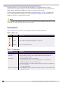
Table 1: Notice icons
Icon
Notice Type
Alerts you to...
Note
Important features or instructions.
Caution
Risk of personal injury, system damage, or loss of data.
Warning
Risk of severe personal injury.
Table 2: Text conventions
Convention
Description
Screen displays
This typeface represents information as it appears on the screen, or command syntax.
The words “enter”
and “type”
When you see the word “enter” in this guide, you must type something, and then
press the Return or Enter key. Do not press the Return or Enter key when an
instruction simply says “type.”
[Key] names
Key names appear in text in one of two ways:
• Referenced by their labels, such as “the Return key” or “the Escape key”
• Written with brackets, such as [Return] or [Esc]
If you must press two or more keys simultaneously, the key names are linked with a
plus sign (+). Example:
Press [Ctrl]+[Alt]+[Del].
Words in italicized type
6
Italics emphasize a point of information or denote new terms at the place where they
are defined in the text.
Extreme Networks Pluggable Interface Modules Installation Guide
Related Publications
Related Publications
The Extreme Networks ExtremeXOS™ switch documentation set includes:
●
ExtremeXOS 12.0 Concepts Guide
●
ExtremeXOS 12.0 Command Reference Guide
●
ExtremeXOS 12.0 Release Notes
●
Extreme Networks BlackDiamond 8800 Series Switch Hardware Installation Guide
●
Extreme Networks BlackDiamond 12800 Series Switch Hardware Installation Guide
●
Extreme Networks BlackDiamond 10808 Switch Hardware Installation Guide
●
Extreme Networks Summit Family Switches Hardware Installation Guide
Documentation for Extreme Networks products is available from the Extreme Networks website at the
following location:
http://www.extremenetworks.com/services/documentation
You can select and download the following Extreme Networks documentation from the Documentation
Overview page:
●
Software User Guides
●
Hardware User Guides
You can find archived user guides for software at:
http://www.extremenetworks.com/services/documentation/swuserguides.asp
You can also find archived installation guides for hardware at:
http://www.extremenetworks.com/services/documentation/hwuserguides.asp
Extreme Networks Pluggable Interface Modules Installation Guide
7
Preface
8
Extreme Networks Pluggable Interface Modules Installation Guide
1
Extreme Networks SFP Modules
This chapter includes the following topics:
●
Overview of SFP Modules on page 9
●
Types of Optical SFP Interfaces on page 9
●
10/100/1000BASE-T Copper SFP Module on page 14
●
Preparing to Install or Replace an SFP Module on page 14
●
Installing an SFP Module on page 14
●
Connecting Fiber Cables on page 16
●
Removing an SFP Module on page 17
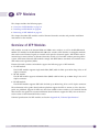
Overview of SFP Modules
Extreme Networks switches support small form factor pluggable (SFP) interface modules, also known
as mini-GBICs. Extreme Networks switches support both optical and copper SFP modules. The types of
switches and the I/O modules determine the compatible type of SFP module.
Use only Extreme Networks-certified SFP modules, available from Extreme Networks, in the SFP port
on the switch or I/O module.
Types of Optical SFP Interfaces
Extreme Networks switches support the following types of optical SFP interfaces:
●
SX SFP module (see page 10)
●
LX SFP module (see page 10)
●
ZX SFP module (see page 11)
●
1000BASE-BX bidirectional SFP modules (see page 11)
■
1000BASE-BX-D
■
1000BASE-BX-U
●
100FX SFP module for Gigabit Ethernet ports (see page 12)
●
Dual-speed 100FX/1000LX SFP module (see page 12)
●
LX100 SFP module (see page 13)
●
100BASE-LX10 SFP module (see page 13)
●
100BASE-BX SFP modules (see page 13)
●
■
100BASE-BX-D
■
100BASE-BX-U
100FX SFP module for 100-Mbps Ethernet (fast Ethernet) ports (see page 14)
Extreme Networks Pluggable Interface Modules Installation Guide
9
Extreme Networks SFP Modules
The information in this guide about hardware platform support for each type of SFPs is current as of
the date this guide was published. Support for specific SFP types may have been added to other
switches or I/O modules besides those listed in this guide. For current information about hardware
support and the minimum required software for SFPs, refer to the most recent version of the
ExtremeXOS release notes.
SX SFP Module
The SX SFP module provides a 1000BASE-T optical connection using LC connectors and multimode
fiber cable up to 300 meters long. The SX SFP module conforms to the 1000BASE-SX standard.
SX SFP modules are supported in the following Extreme Networks switches:
●
BlackDiamond 10808
●
BlackDiamond 8800 series
●
BlackDiamond 12800 series
●
Summit X150 series
●
Summit X250e series
●
Summit X450 series
●
Summit X450a series
●
Summit X450e series
Optical Budget Calculation
When you plan an installation using the SX SFP module, Extreme Networks recommends that 3 dB of
the total budget be reserved for losses induced by cable splices or connectors and operating margin.
There is no minimum attenuation or minimum cable length restriction.
LX SFP Module
The LX SFP module provides a 1000BASE-T optical connection using LC connectors and single-mode
fiber (SMF) cable up to 10 km long. The LX SFP module conforms to the 1000BASE-LX standard.
LX SFP modules are supported on the following Extreme Networks switches:
10
●
BlackDiamond 10808
●
BlackDiamond 8800 series
●
BlackDiamond 12800 series
●
Summit X150 series
●
Summit X250e series
●
Summit X450 series
●
Summit X450a series
●
Summit X450e series
Extreme Networks Pluggable Interface Modules Installation Guide
Types of Optical SFP Interfaces
Optical Budget Calculation
Measure cable plant losses with a 1310 nm light source and verify this to be within budget. When you
calculate the maximum distance attainable using optical cable with a specified loss per kilometer (for
example 0.25 dB/km), Extreme Networks recommends that 3 dB of the total budget be reserved for
losses induced by cable splices or connectors, and operating margin. There is no minimum system
budget or minimum cable length restriction because the maximum receive power is the same as the
maximum transmit power. There is no minimum attenuation or minimum cable length restriction.
ZX SFP Module
The ZX SFP module is a long-haul SFP that provides a 1000BASE-T optical connection using LC
connectors and SMF cable up to 80 km long.
ZX SFP modules are supported on the following Extreme Networks switches:
●
BlackDiamond 10808
●
BlackDiamond 8800 series
●
BlackDiamond 12800 series
●
Summit X150 series
●
Summit X250e series
●
Summit X450 series
●
Summit X450a series
●
Summit X450e series
Optical Budget Calculation
Measure cable plant losses with a 1550 nm light source and verify this to be within budget. When you
calculate the maximum distance attainable using optical cable with a specified loss per kilometer (for
example, 0.25 dB/km), Extreme Networks recommends that you reserve 3 dB of the total budget for
losses induced by cable splices or connectors and operating margin. A minimum system budget or
attenuation is required to prevent saturation of the receiver.
1000BASE-BX Bi-Directional SFP Modules
The 1000BASE-BX SFP modules include the 1000BASE-BX-U SFP module and the 1000BASE-BX-D SFP
module. These two SFP modules are used together to permit a bidirectional Gigabit Ethernet connection
using a single strand of SMF cable and LC connectors. The 1000BASE-BX-D SFP operates at
wavelengths of 1490 nm TX/1310 nm RX, and the 1000BASE-BX-U SFP operates at wavelengths of 1310
nm TX/1490 nm RX. The 1000BASE-BX-U SFP module is always connected to the 1000BASE-BX-D SFP
module. The maximum transmission distance for this connection is 10 km. The 1000BASE-BX SFP
modules conform to the IEEE 802.3ah 1000BASE-BX10 standard.
The 1000BASE-BX SFP modules are supported on the following Extreme Networks switches:
●
BlackDiamond 10808
●
BlackDiamond 8800 series
●
BlackDiamond 12800 series
●
Summit X150 series
Extreme Networks Pluggable Interface Modules Installation Guide
11
Extreme Networks SFP Modules
●
Summit X250e series
●
Summit X450 series
●
Summit X450a series
●
Summit X450e series
100FX SFP Module for Gigabit Ethernet Ports
The 100FX SFP module for Gigabit Ethernet (GE) ports (Model # 10063) provides optical links up to 2
km long using multimode fiber cable. The 100FX SFP for GE ports conforms to the 100FX-MMF
standard.
The 100FX SFP modules are supported in the following Extreme Networks switches:
●
●
BlackDiamond 8800 series
■
G24x I/O module
■
MSM-G8x module
■
G48Xa I/O module
Summit X250e series
■
Summit X250e-24t, X250e-24p, X250-48t, X250e-48t: combination ports only
■
Summit X250e-24x: all ports
●
Summit X450a-24x switch: ports 5 through 24; not supported on combination ports
●
Summit X450a series: not supported on combination ports
Dual-speed 100FX/1000LX SFP Module
The dual-speed 100FX/1000LX SFP module operates at either 100 Mbps or 1000 Mbps over SMF links
up to 10 km long. Operating at 100 Mbps, the dual-speed SFP conforms to the 100BASE-LX standard.
Operating at 1000 Mbps, the dual-speed SFP conforms to the 1000BASE-LX standard.
The dual-speed 100FX/1000FX SFP modules are supported in the following Extreme Networks
switches:
●
BlackDiamond 8800 series
●
BlackDiamond 12800 series
●
Summit X150 series
●
Summit X250e-24t, X250e-24p, X250e-48t, X250e-48p switches: combination ports only
●
Summit X450-24x switch: ports 5 through 24 (not supported on combination ports)
●
Summit X450a-24x, X450a-24xDC switches: ports 1 through 20 (not supported on combination ports)
Optical Budget Calculation
The 100FX/1000LX SFP module complies with the 100FX-SMF standard. To use the 100FX/1000LX SFP
module in 100FX-MMF operation, a minimum attenuation of 6 dB is required. After the SFP module is
installed, connect a 6-dB attenuator to the transmitter side (Tx) of the SFP module. Next, connect the
attenuator to the single-mode end of a mode conditioning patch cord. The mode conditioning patch
cord transitions the SFP module from SMF to MMF operation.
12
Extreme Networks Pluggable Interface Modules Installation Guide
Types of Optical SFP Interfaces
When in SMF operation, 100FX-SMF or 1000LX, measure cable plant losses with a 1310 nm light source
and verify this to be within budget. When you calculate the maximum distance attainable using optical
cable with a specified loss per kilometer (for example 0.25 dB/km), Extreme Networks recommends
that 3 dB of the total budget be reserved for losses induced by cable splices or connectors and operating
margin.
NOTE
The 100FX/1000LX SFP module detects link status based only on the presence of light in the receive cable.
Therefore, if a single strand is broken, the link partner on the other port will not detect link down.
LX100 SFP Module
The LX100 SFP module provides a 1-gigabit optical link up to 100 km long using LC connectors and
SMF cable.
The LX-100 SFP modules are supported on the following Extreme Networks switches:
●
BlackDiamond 10808
●
BlackDiamond 8800 series
●
BlackDiamond 12800 series
●
Summit X150 series
●
Summit X250e series
●
Summit X450 series
●
Summit X450a series
●
Summit X450e series
100BASE-LX10 SFP Module
The 100BASE-LX10 SFP module provides a 100-Mbps optical connection using LC connectors and SMF
cable. The maximum transmission distance for this connection is 10 km.
The LX10 SFP module is supported in the Summit X250e-24x switch in all ports.
100BASE-BX Bi-Directional SFP Modules
The 100BASE-BX SFP modules include the 100BASE-BX-U SFP module and the 100BASE-BX-D SFP
module. These two SFP module are used together in a Summit family switch to permit a bidirectional
100-Mbps Ethernet connection using a single strand of SMF cable and LC connectors. The
100BASE-BX-U SFP module is always connected to the 100BASE-BX-D SFP module. The 100BASE-BX-D
SFP operates at wavelengths of 1550-nm TX/1310-nm RX wavelength), and the 1000BASE-BX-U SFP
operates at wavelengths of 1310 nm TX/1550 nm RX. The maximum transmission distance for this
connection is 10 km. The 100BASE-BX SFP modules conform to the IEEE 802.3ae standard.
The 100BASE-BX SFP modules are supported the Summit X250e-24x switch in all ports.
Extreme Networks Pluggable Interface Modules Installation Guide
13
Extreme Networks SFP Modules
100FX SFP Module for Fast Ethernet Ports
The 100FX SFP module for fast Ethernet (FE) ports (Model # 10067) provides a 100-Mbps optical link
using LC connectors and 1310-nm multimode fiber (MMF) cable. The maximum transmission distance
for this connection is 2 km.
The 100FX SFP module for FE ports is supported in the Summit X250e-24x switch in all ports.
10/100/1000BASE-T Copper SFP Module
The Extreme Networks 10/100/1000BASE-T copper SFP module is compatible with the Gigabit Ethernet
standard and 1000 Base-T standard as specified in the IEEE 802.3:2002 standard. This SFP module
provides a 100-Mbps connection using Category 5 cable.
The 10/100/1000BASE-T SFP module is supported in the following Extreme Networks switches:
●
BlackDiamond 8800 series
●
Summit X450 series
●
Summit X450a series switches.
Preparing to Install or Replace an SFP Module
Complete the following tasks before inserting the SFP module:
1 Inspect and clean the fiber tips, coupler, and connectors.
2 Prepare and clean an external attenuator, if needed.
When handling fiber cables, take the following precautions to prevent damage to the cables:
●
Do not stretch the fiber.
●
Make sure the bend radius of the fiber is not less than 2 inches (5.08 cm).
Extreme Networks recommends the following guidelines when installing or replacing SFP modules on
an active network:
●
Use the same type of SFP module at each end of the link, except for the 1000BASE-BX and
100BSE-BX bi-directional SFP modules. The bi-directional SFP modules include a D-type and a
U-type. You must use one D-type SFP and one U-type SFP together to allow for a single fiber
bidirectional connection.
●
Connect one end of the link to the Tx port. Without an attenuator, measure the total loss from the Tx
port to the other site of the link. The total loss must not exceed the total optical system budget.
Installing an SFP Module
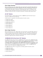
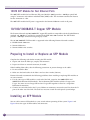
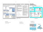
You can add or remove SFP modules in your switch without powering off the system. Figure 1 and
Figure 2 show the types of SFP modules and connectors.
14
Extreme Networks Pluggable Interface Modules Installation Guide
Installing an SFP Module
NOTE
The bi-directional SFP modules combine two SFP optical devices that must be used as a pair to establish the
bidirectional connection over a single fiber. Module C and Module D in Figure 1 show the pair of SFPs for a
bi-directional SFP module.
WARNING!
Optical SFPs contain Class 1 lasers. Invisible laser radiation can occur when laser connections are unplugged. Do
not stare into the beam. This device is compliant with FCC 21 CFR 1040.10 and EN60825-1 A2:2001.
Figure 1: Optical SFP Module Types and Connectors
Module A
Blue
handle
Module B
Purple
handle
Module C
Module D
Bi-directional
modules
Bi-directionalSFP
mini-GBIC
SH_019B
Extreme Networks Pluggable Interface Modules Installation Guide
15
Extreme Networks SFP Modules
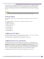
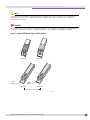
Figure 2: Copper SFP Module
BD_172
CAUTION
To prevent ESD damage to an SFP module, always use an appropriately grounded ESD-preventive wrist strap when
installing or removing the module. Handle the module by its sides only. Never touch the card-edge connectors at the
insertion end of the module.
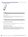
To insert an SFP module:
1 Holding the SFP module by its sides, insert the SFP module into the port on the switch.
2 Slide the SFP module into the port until you hear it click. If the SFP module has a handle, push up
on the handle to secure the SFP module.
NOTE
Disconnect fiber-optic cable from an optical SFP module before removing the SFP module from the port.
Connecting Fiber Cables
Before you connect fiber cables to the dual-speed 100FX/1000LX SFP module or the LX100 SFP module,
note the following information about these SFP modules.
100FX/1000LX SFP Module
The 100FX/1000LX SFP module complies with the 100FX-SMF standard. In order to use the
100FX/1000LX SFP module in 100FX-MMF operation, a minimum attenuation of 6 dB is required. After
the SFP module is installed, connect a 6-dB attenuator to the transmitter side (Tx) of the SFP module.
Then connect the attenuator to the single-mode end of a mode conditioning patch cord. The mode
conditioning patch cord transitions the SFP module from SMF to MMF operation.
16
Extreme Networks Pluggable Interface Modules Installation Guide
Removing an SFP Module
LX100 SFP Module
To prevent permanent damage to the LX100 SFP module, always check the optical input power of the
receiver before you insert the fiber cable. The maximum optical input power is -9 dBm. If you use an
optical loopback for diagnostics, the loopback requires a minimum of 12 dB optical attenuation. The
recommended attenuation range is 12 to 20 dB.
Removing an SFP Module
To remove an SFP module:
1 Disconnect the optical cable from the SFP module.
2 Unlatch the SFP module in one of the following ways:
●
On an SFP module similar to Module A in Figure 1, press and hold the black plastic tab at the
bottom of the connector.
●
On an SFP module similar to Module B, Module C, or Module D in Figure 1, rotate the front
handle down.
3 Pull the SFP module out of the port on the switch.
Extreme Networks Pluggable Interface Modules Installation Guide
17
Extreme Networks SFP Modules
18
Extreme Networks Pluggable Interface Modules Installation Guide
2
XFP Modules
This chapter includes the following topics:
●
Overview of XFP Modules on page 19
●
Installing an XFP Module on page 20
●
Removing an XFP Module on page 22
This chapter describes XFP modules used for Extreme Networks switches and provides installation
instructions for the modules.
Overview of XFP Modules
XFP modules are used in the Summit X450a and X450e series switches, as well as the BlackDiamond
10G4Xa I/O module for the BlackDiamond 8800 series switches. XFP modules are 10-gigabit modules
that convert serial electrical signals to external serial optical or electrical signals. XFP modules can be
inserted into or removed from an Extreme Networks switch or I/O module without powering off the
system. All Extreme Networks XFP modules comply with IEEE 802.3ae standards and with the latest
XFP multi-source agreement (MSA).
Extreme Networks switches and modules support the following types of XFP modules:
●
LR XFP module
The LR XFP module supports single-mode fiber (SMF) cable for links up to 10 km long. It has an LC
duplex connector.
●
SR XFP module
The SR XFP module supports multimode fiber (MMF) cable for links up to 300 m long. It has an LC
duplex connector.
●
ER XFP module
The ER XFP module supports SMF cable for links up to 40 km long. It has an LC duplex connector.
The information in this guide about hardware platform support for XFPs is current as of the date this
guide was published. Support for XFPs may have been added to other switches or I/O modules besides
those listed in this guide. For current information about hardware support for XFPs, refer to the most
recent version of the ExtremeXOS release notes.
Technical specifications for XFP modules are listed in Appendix B, “Technical Specifications.”
Extreme Networks Pluggable Interface Modules Installation Guide
19
XFP Modules
Installing an XFP Module
This section describes how to install an XFP module (Figure 3). You can install or remove an XFP
module in your Extreme Networks switch without powering off the system.
Figure 3: XFP Module
Card edge
connector
XFP Module
SH_022
WARNING!
XFP modules contain Class 1 lasers. Invisible laser radiation can occur when laser connections are unplugged. Do
not stare into the beam. This device is compliant with FCC 21 CFR 1040.10 and EN60825-1 A2:2001.
CAUTION
To prevent ESD damage to the XFP module, always use an appropriately grounded ESD-preventive wrist strap when
installing or removing the module. Handle the module by its sides only. Never touch the card-edge connectors at the
insertion end of the module.
To install an XFP module:
1 Remove the XFP module from its antistatic container and remove the dust covers from the module
optical connectors.
If your module has a protective pad covering the card-edge connector, remove it. Store the antistatic
container, dust covers, and card-edge connector protective pad in a clean location from which they
can be easily retrieved if you need to uninstall the module.
2 Remove any rubber dust covers from the port on the module into which you are installing the XFP
module.
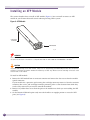
3 On the Summit XGM2-2xf option card, move the handle to an upright position to access the XFP
ports (see Figure 4).
20
Extreme Networks Pluggable Interface Modules Installation Guide
Installing an XFP Module
Figure 4: Accessing the XFP Ports
Summit XGM2-2xf
Option Card
XFP Ports
SH_023
4 Holding the module by its sides, partially insert the XFP module into one of the ports on the Summit
XGM2-2xf option card or the 10G4Xa module (see Figure 5).
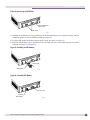
5 Push the XFP handle (bail latch) upward until it clicks into place (see Figure 5).
6 Slide the XFP module as far as possible into the slot until you hear it click, indicating that it is firmly
attached (see Figure 5 and Figure 6).
Figure 5: Installing an XFP Module
XFP Handle
XFP Module
SH_024
Figure 6: Installed XFP Module
Cover Plate
Installed
XFP Module
SH_025
Extreme Networks Pluggable Interface Modules Installation Guide
21
XFP Modules
NOTE
If you are installing only one XFP module, make sure that all unoccupied ports are covered with a rubber dust cover,
which is shipped with the option card (see Figure 6).
NOTE
To ensure that your XFP module is undamaged upon installation, you can correlate factory test data with your
installation site test data by consulting the average power reference values shown on the XFP module test data sheet
(Part No. 121080-00) enclosed with the module.
Removing an XFP Module
This section describes how to remove an XFP module. You can remove an XFP module from your
Extreme Networks switch or I/O module without powering off the system. The XFP module is shown
in Figure 3 on page 20.
To remove an XFP module:
1 Release the handle (bail latch) on the XFP module.
2 Carefully pull the XFP module out of the port.
3 Place the dust covers back into the XFP module connectors.
4 Place the XFP module immediately into an antistatic container to protect it from ESD damage and
dust.
22
Extreme Networks Pluggable Interface Modules Installation Guide
3
XENPAK Transceivers
This chapter provides important safety information and installation instructions for the XENPAK
optical transceiver modules used in Extreme Networks equipment.
This chapter includes the following topics:
●
Overview of XENPAK Modules on page 23
●
Installing and Removing a XENPAK Module on page 27
Overview of XENPAK Modules
The BlackDiamond 8800 series of switches, the BlackDiamond 10808 switch, the BlackDiamond 12800
series of switches, and the Summit family of switches support several types of XENPAK transceiver
modules. All of these modules conform to the 10 Gigabit Ethernet standard defined by the IEEE 802.3ae
as applicable
CAUTION
XENPAK modules contain Class 1 laser devices. Invisible laser radiation can occur when the connectors are open.
Do not stare into the beam. This device is compliant with FCC 21 CFR 1040.10, 1040.11 and EN60825-1
A2:2001.
Extreme Networks switches and modules support the following types of XENPAK interfaces:
●
SR XENPAK on page 24
●
LR XENPAK on page 24
●
ER XENPAK on page 25
●
ZR XENPAK on page 25
●
LX4 XENPAK on page 26
●
LW XENPAK on page 26
NOTE
CX4 XENPAKs are also supported by Extreme Networks devices; contact your vendor to obtain these.
NOTE
Use only Extreme Networks-approved XENPAK modules in all Extreme Networks devices.
Extreme Networks Pluggable Interface Modules Installation Guide
23
XENPAK Transceivers
SR XENPAK
The SR XENPAK supports multimode fiber (MMF) and has SC connectors.
The SR XENPAK requires the software versions listed in Table 3.
Table 3: SR XENPAK software requirements
Switch Model
Required Software
BlackDiamond Switches
BlackDiamond 10808
ExtremeXOS 11.1.1 or later
BlackDiamond 8800 series
ExtremeXOS 11.1.1 or later
BlackDiamond 12804
ExtremeXOS 11.4 or later
BlackDiamond 12802
ExtremeXOS 12.0 or later
Summit Switches
Summit X450 series
ExtremeXOS 11.2.0 or later
Summit X450a series
ExtremeXOS 11.2.0 or later
Summit X450e series
ExtremeXOS 11.2.0 or later
For technical specifications for the SR XENPAK, see Appendix B, “Technical Specifications.”
LR XENPAK
The LR XENPAK supports single-mode fiber (SMF) and has SC connectors.
The LR XENPAK requires the software versions listed in Table 4.
Table 4: LR XENPAK software requirements
Switch Model
Required Software
BlackDiamond Switches
BlackDiamond 10808
ExtremeXOS 11.1.1 or later
BlackDiamond 8800 series
ExtremeXOS 11.1.1 or later
BlackDiamond 12804
ExtremeXOS 11.4 or later
BlackDiamond 12802
ExtremeXOS 12.0 or later
Summit Switches
Summit X450 series
ExtremeXOS 11.2.0 or later
Summit X450a series
ExtremeXOS 11.2.0 or later
Summit X450e series
ExtremeXOS 11.2.0 or later
For technical specifications for the LR XENPAK, see Appendix B, “Technical Specifications.”
24
Extreme Networks Pluggable Interface Modules Installation Guide
Overview of XENPAK Modules
ER XENPAK
The ER XENPAK supports SMF and has SC connectors.
The ER XENPAK requires the software versions listed in Table 5.
Table 5: ER XENPAK software requirements
Switch Model
Required Software
BlackDiamond Switches
BlackDiamond 10808
ExtremeXOS 11.1.1 or later
BlackDiamond 8800 series
ExtremeXOS 11.1.1 or later
BlackDiamond 12804
ExtremeXOS 11.4 or later
BlackDiamond 12802
ExtremeXOS 12.0 or later
Summit Switches
Summit X450 series
ExtremeXOS 11.2.0 or later
Summit X450a series
ExtremeXOS 11.2.0 or later
Summit X450e series
ExtremeXOS 11.2.0 or later
For technical specifications for the ER XENPAK, see Appendix B, “Technical Specifications.”
ZR XENPAK
The ZR XENPAK supports SMF and has SC connectors.
The ZR XENPAK requires the software versions listed in Table 6.
Table 6: ZR XENPAK software requirements
Switch Model
Required Software
BlackDiamond Switches
BlackDiamond 10808
ExtremeXOS 11.3.1 or later
BlackDiamond 8800 series
ExtremeXOS 11.3.1 or later
BlackDiamond 12804
ExtremeXOS 11.4 or later
BlackDiamond 12802
ExtremeXOS 12.0 or later
Summit Switches
Summit X450 series
ExtremeXOS 11.3.1 or later
Summit X450a series
ExtremeXOS 11.3.1 or later
Summit X450e series
ExtremeXOS 11.3.1 or later
For technical specifications for the ZR XENPAK, see Appendix B, “Technical Specifications.”
WARNING!
To prevent permanent damage to the ZR XENPAK and other equipment: always check the optical input power of the
receiver before inserting the fiber. The maximum optical input power for the receiver is -7 dBm. If you use optical
loopback for diagnostics purposes, the loopback requires a minimum of 10 dB optical attenuation. The
recommended attenuation range is 10 dB to 15 dB.
Extreme Networks Pluggable Interface Modules Installation Guide
25
XENPAK Transceivers
LX4 XENPAK
The LX4 XENPAK supports multimode fiber (MMF) in intra-building connections and single-mode fiber
(SMF) for interbuilding connections. The LX4 XENPAK has SC connectors.
The LX4 XENPAK requires the software versions listed in Table 7.
Table 7: LX4 XENPAK Software Requirements
Switch Model
Required Software
BlackDiamond Switches
BlackDiamond 10808
ExtremeXOS 11.3.1 or later
BlackDiamond 8800 series
ExtremeXOS 11.3.1 or later
BlackDiamond 12804
ExtremeXOS 11.4 or later
BlackDiamond 12802
ExtremeXOS 12.0 or later
Summit Switches
Summit X450 series
ExtremeXOS 11.3.1 or later
Summit X450a series
ExtremeXOS 11.3.1 or later
Summit X450e series
ExtremeXOS 11.3.1 or later
For technical specifications for the LX4 XENPAK, see Appendix B, “Technical Specifications.”
LW XENPAK
To recognize the LW XENPAK module, your Extreme Networks switch must have the minimum
software release listed in Table 8.
Table 8: LW XENPAK Software Requirements
Switch Model
Required Software Release
BlackDiamond Switches
BlackDiamond 10808
ExtremeXOS 11.4.1 or later
BlackDiamond 12804
ExtremeXOS 11.4.1 or later
BlackDiamond 12802
ExtremeXOS 12.0 or later
Summit Switches
Summit X450a
ExtremeXOS 11.5.0 or later
Summit X450e
ExtremeXOS 11.5.0 or later
NOTE
BlackDiamond 10808 switches and BlackDiamond 12804 switches running software earlier than ExtremeXOS
11.4.2.3 do not support jumbo-size frame for the LW XENPAK. These switches support only standard-size frame for
the LW XENPAK.
BlackDiamond 10808 switches and BlackDiamond 12804 switches running the latest version of ExtremeXOS 11.4
support jumbo-size frame for the LW XENPAK with a 5% decrease in performance, allowing for 95% of the
maximum WAN PHY traffic.
26
Extreme Networks Pluggable Interface Modules Installation Guide
Installing and Removing a XENPAK Module
ExtremeXOS 11.5.0 or later supports the LW XENPAK at full functionality with 100% performance in the Summit
X450a and X450e series switches.
CAUTION
The maximum input power (average receive power) should be less than 0.5 dBm.
Transmitter Clock Locking Mode
The LW XENPAK module provides an interface connection between a 10-gigabit Ethernet and a 10gigabit SONET/SDH network from a 10-gigabit Ethernet equipment port.
The default transmitter clock locking mode of the LW XENPAK module is set to line timing mode.
When in line timing mode, the LW XENPAK module transmitter clock is locked to the receiverrecovered clock. When the LW XENPAK is connected to the SONET/SDH network on the other side of
optical cable, the LW XENPAK transmitter clock synchronizes with the SONET/SDH clock source,
which helps reduce the pointer adjustment between the SONET/SDH network and the LW XENPAK.
To prevent a clock reference loop, be sure that only one end of a link is using line timing mode and to
use internal timing when testing with an optical loopback cable.
Installing and Removing a XENPAK Module
WARNING!
XENPAK modules become very hot after prolonged use. Be careful when removing a XENPAK module from the
chassis or option card. If the XENPAK module is too hot to touch, disengage the XENPAK module and allow it to
cool before removing it completely.
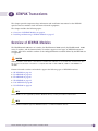
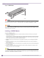
This section describes installing and removing the XENPAK module (Figure 7). You can install or
remove the XENPAK module from your Extreme Networks switch without powering off the system.
NOTE
On a Summit X450 series, X450a series, or X450e series switch, the XENPAK module is inserted into an optional
module card. Although the module card is not hot-swappable, you can hot swap the XENPAK into and out of the
module card on the Summit. For information about the optional module card for XENPAKs on a Summit X450
series, X450a series, or X450e series switch, see the Summit Family Switches Hardware Installation Guide.
Extreme Networks Pluggable Interface Modules Installation Guide
27
XENPAK Transceivers
Figure 7: XENPAK Module
Card edge
connector
EWUG003B
WARNING!
XENPAK modules contain Class 1 lasers. Invisible laser radiation can occur when laser connections are unplugged.
Do not stare into the beam. This device is compliant with FCC 21 CFR 1040.10 and EN60825-1 A2:2001.
CAUTION
To prevent ESD damage to the XENPAK module, always use an appropriately grounded ESD-preventive wrist strap
when installing or removing the module. Handle the module by its sides only. Never touch the card-edge connectors
at the insertion end of the module.
Installing a XENPAK Module
To install a XENPAK module:
1 Remove the XENPAK module from its antistatic container and remove the dust covers from the
module optical connectors.
If your module has a protective pad covering the card-edge connector, remove it. Store the antistatic
container, dust covers, and card-edge connector protective pad in a clean location from which they
can be easily retrieved if you need to uninstall the module.
2 Remove any dust covers from the port on the module into which you are installing the XENPAK
module.
3 Holding the module by its sides, insert the XENPAK module into the slot on the I/O module or
Summit option card.
4 Slide the XENPAK module as far back into the slot as possible, until you hear it click, indicating that
it is firmly attached.
5 Secure the XENPAK module to the I/O module or option card by turning the two captive screws
clockwise until the screws are hand-tight.
NOTE
To ensure that your XENPAK module is undamaged upon installation, you can correlate factory test data with your
installation site test data by consulting the average power reference values shown on the XENPAK module test data
sheet (Part No. 121074-00) enclosed with your module.
28
Extreme Networks Pluggable Interface Modules Installation Guide
Installing and Removing a XENPAK Module
Removing a XENPAK Module
To remove a XENPAK module:
1 Disconnect the optical cable from the XENPAK module.
WARNING!
XENPAK modules contain Class 1 lasers. Invisible laser radiation can occur when laser connections are unplugged.
Do not stare into the beam.
2 Loosen the two captive screws until they are completely free from the I/O module faceplate or the
Summit option card. (The captive screws remain attached to the XENPAK module.)
3 Gripping both captive screws, carefully pull the XENPAK module out of the slot.
4 Place the dust covers back into the XENPAK module connectors.
5 Place the XENPAK module immediately into an antistatic container to protect it from ESD damage
and dust.
Extreme Networks Pluggable Interface Modules Installation Guide
29
XENPAK Transceivers
30
Extreme Networks Pluggable Interface Modules Installation Guide
A
Safety Information
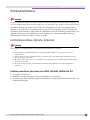
WARNING!
Read the following safety information thoroughly before installing Extreme Networks products. Failure to follow this
safety information can lead to personal injury or damage to the equipment.
Only trained service personnel should perform service to Extreme Networks switches and their
components. Trained service personnel have read all related installation manuals, have the technical
training and experience necessary to be aware of the hazards to which they are exposed in performing a
task, and are aware of measures to minimize the danger to themselves or other persons.
Fiber Optic Ports—Optical Safety
The following safety warnings apply to all optical devices used in Extreme Networks equipment that
are removable or directly installed in an I/O module or chassis system. These devices include, but are
not limited to, the following devices:
●
SC gigabit interface converters (GBICs)
●
SFP GBICs (mini-GBICs)
●
XENPAKs
●
XFP laser optic modules
CAUTION
Laser optic modules become very hot after prolonged use. Take care when removing a laser optic module from the
chassis or option card. If the laser optic module is too hot to touch, disengage the laser optic module and allow it to
cool before removing it completely.
WARNING!
When working with laser optic modules, always take the following precautions to prevent exposure to hazardous
radiation:
●
Never look at the transmit LED/laser through a magnifying device while it is powered on.
●
Never look directly at a fiber port on the switch or at the ends of a fiber cable when they are powered on.
●
Invisible laser radiation can occur when the connectors are open. Avoid direct eye exposure to the beam
when optical connections are unplugged.
●
Never alter, modify, or change an optical device in any way other than suggested in this document.
Extreme Networks Pluggable Interface Modules Installation Guide
31
Safety Information
GBIC, Mini-GBIC, XENPAK, and XFP Regulatory Compliance
●
Class 1 Laser Product
●
EN60825-1+A2:2001 or later, European laser standard
●
FCC 21 CFR Chapter 1, Subchapter J in accordance with FDA & CDRH requirements
●
Application of CE Mark in accordance with 89/336/EEC EMC and 73/23/EEC Low Voltage
Directives
●
UL and/or CSA registered component for North America
●
47 CFR Part 15, Class A when installed into Extreme products
Using Third-Party Optical Modules
Extreme Networks optical modules are tested to work in all supported Extreme Networks switches. We
recommend that all customers use Extreme Networks optical modules in their Extreme Networks
switches. Extreme Networks assumes no liability for third-party optical modules. Although Extreme
Networks does not block third-party optical modules, we cannot ensure that all third-party optical
modules operate properly in all Extreme Networks switches. The customer assumes all risks associated
with using third-party optical modules in Extreme Networks switches.
32
Extreme Networks Pluggable Interface Modules Installation Guide
Fiber Optic Ports—Optical Safety
Sicherheitshinweise
WARNUNG!
Vor der Installation der Produkte von Extreme Networks sind die nachfolgenden Sicherheitshinweise aufmerksam zu
lesen. Die Nichtbeachtung dieser Sicherheitshinweise kann zu Verletzungen oder Schäden an der Ausrüstung führen.
Installation, Wartung und Ausbau eines Switch, einer Grundplatte oder einer seiner Komponenten
dürfen nur von geschultem und qualifiziertem Servicepersonal durchgeführt werden! Geschulte und
qualifizierte Servicetechniker verfügen über die erforderliche technische Ausbildung und Erfahrung, um
mögliche Gefahren bei der Durchführung von Servicearbeiten zu erkennen und Maßnahmen zur
Minimierung der Gefahr für sich bzw. andere zu treffen.
Lichtleiteranschlüsse: Optische Sicherheit
WARNUNG!
Beim Umgang mit Lichtleitermodulen sind folgende Vorsichtsmaßnahmen zu beachten:
●
Niemals durch ein Vergrößerungsgerät auf die übertragende LED/den Laser schauen, wenn diese(r)
eingeschaltet ist.
●
Niemals direkt auf einen Lichtleiteranschluss am Switch oder auf die Enden eines Faserkabels schauen,
wenn diese eingeschaltet sind.
●
Bei offenen Anschlüssen kann es zu unsichtbarer Laserstrahlung kommen. Direkter Augenkontakt mit dem
Strahl ist zu vermeiden.
●
Ein optisches Gerät niemals auf andere Weise verändern oder modifizieren als in diesem Dokument
angegeben.
Einhaltung behördlicher Vorschriften durch GBIC, Mini-GBIC, XENPAK und XFP
●
Laserprodukt der Klasse 1
●
EN60825-1+A2:2001 oder jünger, Europäische Richtlinie für Lasersysteme
●
Anwendung der CE-Kennzeichnung gemäß der Richtlinien 89/336/EWG EMV und 73/23/EWG für
Niederspannungsgeräte
Extreme Networks Pluggable Interface Modules Installation Guide
33
Safety Information
34
Extreme Networks Pluggable Interface Modules Installation Guide
B
Technical Specifications
This appendix includes the following technical specifications:
●
SFP Specifications on page 35
●
XFP Technical Specifications on page 40
●
XENPAK Technical Specifications on page 42
●
Pluggable Interface Module Regulatory Compliance on page 45
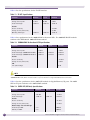
SFP Specifications
The SX SFP conforms to the 1000BASE-SX standard. Table 9 lists the specifications for the SX SFP
interface.
Table 9: SX SFP Specifications
Parameter
Minimum
Typical
Maximum
Transmitter
Average launch power
-9.5 dBm
Center wavelength
830 nm
-4 dBm
850 nm
860 nm
Receiver
Receive sensitivity
-17 dBm
Average receive power (max)
0 dBm
Operating wavelength
770 nm
850 nm
860 nm
Link
Link power budget
7.5 dB
The LX SFP conforms to the 1000BASE-LX standard. Table 10 lists the specifications for the LX SFP
interface.
Table 10: LX SFP Specifications
Parameter
Minimum
Typical
Maximum
Transmitter
Average launch power
-11 dBm
Center wavelength
1270 nm
-3 dBm
1310 nm
1355 nm
Receiver
Receive sensitivity
-19 dBm
Average receive power (max)
Operating wavelength
-3 dBm
1270 nm
1310 nm
1355 nm
Link
Link power budget
Extreme Networks Pluggable Interface Modules Installation Guide
8 dB
35
Technical Specifications
Table 11 lists the specifications for the ZX SFP interface.
Table 11: ZX SFP Specifications
Parameter
Minimum
Typical
Maximum
Average launch power
-2 dBm
0 dBm
3 dBm
Center wavelength
1540 nm
1550 nm
1570 nm
Transmitter
Receiver
Receive sensitivity
-23 dBm
Average receive power (max)
Operating wavelength
-3 dBm
1540 nm
1550 nm
1570 nm
Table 12 lists specifications for the 1000BASE-BX bi-directional SFPs. The 1000BASE-BX SFP modules
conform to the IEEE 802.3ah 1000BASE-BX10 standard.
Table 12: 1000BASE-BX Bi-directional SFP Specifications
Parameter
Minimum
Typical
Maximum
Transmitter
Average launch power
-9 dBm
-3 dBm
Center wavelength (1000BASE-BX10-D)
1480 nm
1490 nm
1550 nm
Center wavelength (1OOOBASE-BX10-U)
1260 nm
1310 nm
1360 nm
Receiver
Receive sensitivity
-19 dBm
Average receive power (max)
-3 dBm
Link
Link power budget
8 dB
NOTE
The 1000BX bidirectional SFPs include two SFP optical devices, the 1000BASE-BX-U SFP and the
1000BASE-BX-D SFP, which must be used as a pair to allow for a single fiber bidirectional connection.
Table 13 lists the specifications for the 100FX SFP module for Gigabit Ethernet (GE) ports. The 100FX
SFP for GE ports conforms to the 100FX-MMF standard.
Table 13: 100FX SFP (GE Ports) Specifications
Parameter
Minimum
Typical
Maximum
Transmitter
Average launch power
-20 dBm
Center wavelength
1270 nm
-14 dBm
1310 nm
1380 nm
Receiver
Receive sensitivity
-31 dBm
Average receive power (max)
-14 dBm
Distance range over each fiber type
36
62.5/125 μm MMF
2m
2000 m
50/125 μm MMF
2m
2000 m
Extreme Networks Pluggable Interface Modules Installation Guide
SFP Specifications
Table 14 lists the specifications for the dual-speed 100FX/1000LX SFP module for Gigabit Ethernet (GE)
ports. Operating at 100 Mbps, the dual-speed SFP conforms to the 100BASE-LX10 standard. Operating
at 1000 Mbps, the dual-speed SFP conforms to the 1000BASE-LX standard.
Table 14: Dual-speed 100FX/1000LX SFP Specifications
Parameter
100FX
1000LX
Connector type
LC
LC
Average launch power range with 9 um SMF
-8 dBm to -15 dBm
-3 dBm to -11 dBm
Receiver power range with 9 um SMF
-8 dBm to -25 dBm
-3 dBm to -19 dBm
Optical link budget with 9 um SMF
10 dB
8dB
Center wavelength range
1270 to 1355
1270 to 1355
Distance range over each optical fiber type (see note below table)
62.5/125 μm MMF
2 to 2000 m
2 to 550 m
50/125 μm MMF
2 to 2000 m
2 to 550 m
9/125 μm SMF
2 to 10,000 m
2 to 10,000 m
NOTE
The 100FX/1000LX SFP module complies with the 100FX-SMF standard. To use the 100FX/1000LX SFP module in
100FX-MMF operation, a minimum attenuation of 6 dB is required. After the SFP module is installed, connect a
6-dB attenuator to the transmitter side (Tx) of the SFP module. Next, connect the attenuator to the single-mode end
of a mode conditioning patch cord. The mode conditioning patch cord transitions the SFP module from SMF to MMF
operation.
Table 16 lists specifications for the LX100 SFP module.
Table 15: LX100 SFP specifications
Parameter
Minimum
Typical
Maximum
Average launch power
1 dBm
3 dBm
5 dBm
Center wavelength
1540 nm
1550 nm
1570 nm
Transmitter
Receiver
Receive sensitivity
–29 dBm
Average receive power
Operating wavelength
–9 dBm
1540 nm
1550 nm
Extreme Networks Pluggable Interface Modules Installation Guide
1570 nm
37
Technical Specifications
Table 16 lists specifications for the 100BASE-LX10 SFP module.
Table 16: 100BASE-LX10 SFP Specifications
Parameter
Minimum
Typical
Maximum
Average launch power
–15 dBm
–10 dBm
–8 dBm
Center wavelength
1260 nm
1310 nm
1360 nm
Transmitter
Receiver
Receive sensitivity
–25 dBm
Average receive power
Operating wavelength
–8 dBm
1260 nm
1310 nm
1360 nm
Table 17 lists specifications for the 100BX Bi-directional SFPs. The 100BASE-BX SFP modules conform to
the IEEE 802.3ae standard.
Table 17: 100BASE-BX Bi-directional SFP Specifications
Parameter
Minimum
Typical
Maximum
Transmitter
Average launch power
–14 dBm
–8 dBm
Center wavelength (100BASE-BX10-D)
1480 nm
1550 nm
1580 nm
Center wavelength (1OOBASE-BX10-U)
1260 nm
1310 nm
1360 nm
Receiver
Receive sensitivity
–28.2 dBm
Average receive power (max)
–8 dBm
Link
Link power budget
14.2 dB
NOTE
The 100BX bidirectional SFPs include two SFP optical devices, the 100BASE-BX-U SFP and the 100BASE-BX-D
SFP, which must be used as a pair to allow for a single fiber bidirectional connection.
38
Extreme Networks Pluggable Interface Modules Installation Guide
SFP Specifications
Table 13 lists the specifications for the 100BASE-FX SFP module for fast Ethernet (FE) FE ports.
Table 18: 100BASE-FX SFP for FE ports Specifications
Parameter
Minimum
Typical
Maximum
Transmitter
Average launch power
-20 dBm
Center wavelength
1270 nm
-14 dBm
1310 nm
1380 nm
Receiver
Receive sensitivity
-31 dBm
Average receive power (max)
-14 dBm
Distance range over each fiber type
62.5/125 μm MMF
2m
2000 m
50/125 μm MMF
2m
2000 m
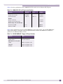
Table 19 lists specifications for the 10/100/1000BASE-T copper SFP module. The 10/100/1000BASE-T
copper SFP module is compatible with the Gigabit Ethernet standard and 1000 Base-T standard as
specified in the IEEE 802.3:2002 standard.
Table 19: 10/100/1000BASE-T Copper SFP Specifications
Parameter
Value
Input voltage range
3.3 V ± 5%
Supply current
375 mA maximum
Link distance for each speed
1 Gbps
100 m using Cat5 cable
100 Mbps
150 m using Cat5 cable
10 Mbps
250 m using Cat5 cable
Extreme Networks Pluggable Interface Modules Installation Guide
39
Technical Specifications
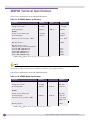
XFP Technical Specifications
Table 20 lists the specifications for the LR XFP module.
Table 20: LR XFP Module Specifications
Parameter
Minimum
Typical
Maximum
Transmitter
Average launch power
-8.2 dBm
Center wavelength
1260 nm
1310 nm
0.5 dBm
1260 nm
1310 nm
1355 nm
Receiver
Average receiver power (max)
Center wavelength
0.5 dBm
1355 nm
Stressed receiver sensitivity in OMA
-10.3 dBm
0.093 mW1
Operating distance
10 km
1.OMA=10log10[2P{(A-1)/(A+1)}], A = 10(Er/10), P = 10(Pf/10)
Table 21 lists specifications for the ER XFP module.
Table 21: ER XFP Module Specifications
Parameter
Minimum
Typical
Maximum
Transmitter
Average launch power
–4.7 dBm
4 dBm
Center wavelength
1530 nm
1565 nm
Average receiver power (max)
–11.8 dBm
–1 dBm
Center wavelength
1260 nm
1580 nm
Receiver
Maximum receiver sensitivity in OMA
?14.1 dBm1
Operating distance
40 km
1.OMA=10log10[2P{(A-1)/(A+1)}], A = 10(Er/10), P = 10(Pf/10)
40
Extreme Networks Pluggable Interface Modules Installation Guide
XFP Technical Specifications
Table 22 lists specifications for the SR XFP module.
Table 22: SR XFP Module Specifications
Parameter
Minimum
Typical
Maximum
Transmitter
Average launch power
-7.3 dBm
Center wavelength
840 nm
–1.3 dBm
850 nm
860 nm
Receiver
Average receiver power (max)
–9.9 dBm
–1 dBm
Center wavelength
840 nm
860 nm
Maximum receiver sensitivity in OMA
-11.1 dBm1
Operating distance
300 m
Operating distance range
(depends on type and modal
bandwidth)
62.5 μm MMF (160 MHz*km)
62.5 μm MMF (200 MHz*km)
50 μm MMF (400 MHz*km)
50 μm MMF (500 MHz*km)
50 μm MMF (2000 MHz*km)
26 m
33 m
66 m
82 m
300 m
1.OMA=10log10[2P{(A-1)/(A+1)}], A = 10(Er/10), P = 10(Pf/10)
Extreme Networks Pluggable Interface Modules Installation Guide
41
Technical Specifications
XENPAK Technical Specifications
Table 23 lists specifications for the SR XENPAK module
.
Table 23: SR XENPAK Module Specifications
Parameter
Minimum
Typical
Maximum
Transmitter
Average launch power
-7.3 dBm
Center wavelength
840 nm
–1.3 dBm
850 nm
860 nm
Receiver
Average receiver power (max)
–9.9 dBm
–1 dBm
Center wavelength
840 nm
860 nm
Maximum receiver sensitivity in OMA
-11.1 dBm1
Operating distance
300 m
Operating distance range
(depends on type and modal bandwidth)
62.5 μm MMF (160 MHz*km)
62.5 μm MMF (200 MHz*km)
50 μm MMF (400 MHz*km)
50 μm MMF (500 MHz*km)
50 μm MMF (2000 MHz*km)
26 m
33 m
66 m
82 m
300 m
1.OMA=10log10[2P{(A-1)/(A+1)}], A = 10(Er/10), P = 10(Pf/10)
NOTE
The launch power (measured using the average power method used by power meters) is measured at the factory. The
average launch power minimum value is provided as a reference, not a pass/fail criterion.
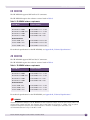
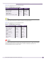
Table 24 lists specifications for the LR XENPAK module.
Table 24: LR XENPAK Module Specifications
Parameter
Minimum
Maximum
Average launch power
-8.2 dBm
0.5 dBm
Center wavelength
1260 nm
Transmitter
1310 nm
1355 nm
Receiver
Average receiver power (max)
Center wavelength
0.5 dBm
1260 nm
1310 nm
1355 nm
Stressed receiver sensitivity in OMA
-10.3 dBm
0.093 mW1
Operating distance
10 km
1.OMA=10log10[2P{(A-1)/(A+1)}], A = 10(Er/10), P = 10(Pf/10)
42
Extreme Networks Pluggable Interface Modules Installation Guide
XENPAK Technical Specifications
Table 25 lists specifications for the ER XENPAK module.
Table 25: ER XENPAK Module Specifications
Parameter
Minimum
Maximum
Average launch power
-4.7 dBm
4.0 dBm
Optical link budget
10.9 dB
Wavelength range
1530 nm
1565 nm
Distance range:
5 dBm attentuation
2m
40 km
Maximum receiver sensitivity in OMA
-14.1 dBm
NOTE
The launch power (measured using the average power method used by power meters) is measured at the factory. The
average launch power minimum value is provided as a reference, not a pass/fail criterion.
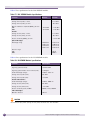
Table 26 lists specifications for the ZR XENPAK module
.
Table 26: ZR XENPAK Module Specifications
Parameter
Minimum
Maximum
Optical output power
0 dBm
4 dBm
Center wavelength
1530 nm
1565 nm
Optical input power
-22 dBm
-7 dBm
Operating wavelength
1530 nm
1565 nm
Optical link loss
11 dB
22 dB
Optical dispersion
0 ps/nm
1600 ps/nm
Transmitter
Receiver
General
Distance
80 km
WARNING!
To prevent permanent damage to the ZR XENPAK and other equipment: always check the optical input power of the
receiver before inserting the fiber. The maximum optical input power for the receiver is -7 dBm. If you use optical
loopback for diagnostics purposes, the loopback requires a minimum of 10 dB optical attenuation. The
recommended attenuation range is 10 dB to 15 dB.
Extreme Networks Pluggable Interface Modules Installation Guide
43
Technical Specifications
Table 27 lists specifications for the LX4 XENPAK module.
Table 27: LX4 XENPAK Module Specifications
Parameter
Minimum
Maximum
Transmitter
Average launch power, 4 lanes
+ 5.5 dBm
Average launch power, per lane
- 0.5 dBm
Optical modulation amplitude (OMA), per lane:
SMF
MMF
- 6.25 dBm
- 6.75 dBm
- 1.25 dBm
- 1.25 dBm
Receiver
Average receive power, 4 lanes
+ 5.5 dBm
Average receive power, per lane
- 0.5 dBm
Receive sensitivity (OMA), per lane
- 14.45 dBm
Optical link budget
Wavelength range
1269.0
1293.5
1318.0
1342.5
nm
nm
nm
nm
Distance range:
SMF
MMF
1282.4
1306.9
1331.4
1355.9
nm
nm
nm
nm
10 km
300 m
Table 28 lists specifications for the LW XENPAK module.
Table 28: LW XENPAK Module Specifications
Parameter
Measurement
Transmitter Characteristics
Signaling speed (nominal)
9.95328 GBd
Signaling speed variation from nominal (max)
+/-20 ppm
Center wavelength (range)
1260 to 1355 nm
Average launch power (max)
0.5 dBm
Average launch power (min)
-8.2 dBm
Receiver Characteristics
Center wavelength (range)
1260 to 1600 nm
Average receive power (max)
0.5 dBm
Average receive power (min)
-14.4 dBm
Receive sensitivity (max) in OMA
0.055 (-12.6) uW/dBm
Link Power Budget
Operation distance
10 Km
CAUTION
The maximum input power (average receive power) should be less than 0.5 dBm.
44
Extreme Networks Pluggable Interface Modules Installation Guide
Pluggable Interface Module Regulatory Compliance
Pluggable Interface Module Regulatory Compliance
Extreme Networks pluggable interface modules comply with the following agency requirements:
●
Class 1 Laser Product (optical modules only)
●
EN60825-1+A2:2001 or later, European laser standard (optical modules only)
●
FCC 21 CFR Chapter 1, Subchapter J in accordance with FDA & CDRH requirements (optical
modules only)
●
Application of CE Mark in accordance with 89/336/EEC EMC and 73/23/EEC Low Voltage
Directives
●
UL and/or CSA registered component for North America
●
47 CFR Part 15, Class A when installed into Extreme products
Extreme Networks Pluggable Interface Modules Installation Guide
45
Technical Specifications
46
Extreme Networks Pluggable Interface Modules Installation Guide
Index
Numerics
D
10 Gbps optical transceiver, 27
10/100/1000-BASE-T copper SFP
specifications, 39
10/100/1000BASE-T copper SFP
hardware platform support, 14
1000BASE-BX SFP
hardware platform support, 11
specifications, 36
100BASE-BX SFP
hardware platform support, 13
specifications, 38
100BASE-LX10 SFP
hardware platform support, 13
specifications, 38
100FX SFP (FE ports), 39
hardware platform support, 14
specifications, 39
100FX SFP (GE ports)
hardware platform support, 12
specifications, 36
100FX/1000LX SFP
hardware platform support, 12
optical system budget, 12
specifications, 37
dual-speed SFP, 12
B
bidirectional SFPs, 11, 13
C
components, installing
SFP, 14
XENPAK module, 28
XFP module, 20
components, removing
SFP, 17
XENPAK module, 29
XFP, 22
XFP module, 22
conventions
notice icons, 6
text, 6
Extreme Networks Pluggable Interface Modules Installation Guide
E
ER XENPAK, 43
ER XFP, 19, 40
F
fiber cables, handling, 14
H
hardware platform support
10/100/1000BASE-T copper SFP, 14
1000BASE-BX SFP, 11
100BASE-BX SFP, 13
100BASE-LX10 SFP, 13
100FX SFP (FE ports), 14
100FX SFP (GE ports), 12
100FX/1000LX SFP, 12
LX SFP, 10
LX100 SFP, 13
SX SFP, 10
XENPAK, 23
XFP, 19
ZX SFP, 11
I
installation
SFP, 14
XENPAK, 28
XFP, 20
L
LR XENPAK, 42
LR XFP, 19, 40
LW XENPAK, 44
LX SFP
hardware platform support, 10
optical system budget, 11
specifications, 35
LX100 SFP
hardware platform support, 13
specifications, 37
47
Index
LX4 XENPAK, 44
M
mini-GBIC. See SFP
O
optical module types
SFP, 9
XENPAK, 23
XFP, 19
optical port safety, 31
optical system budget
100FX/1000LX SFP, 12
LX SFP, 11
SX SFP, 10
ZX SFP, 11
R
regulatory compliance, 32
related publications, 7
removal
SFP, 17
XFP, 22
S
safety requirements, 31
SFP
pre-installation tasks, 14
specifications
1000BASE-BX, 36
100BASE-BX, 38
100FX (FE ports), 39
100FX (GE ports), 36
100FX/1000LX, 37
LX, 35
SX, 35
ZX, 36
types, 9
specifications, 39
1000BASE-BX SFP, 36
100BASE-BX SFP, 38
100BASE-LX10 SFP, 38
100FX SFP (FE ports), 39
100FX SFP (GE ports), 36
100FX/1000LX SFP, 37
ER XFP, 40
LR XFP, 40
LX SFP, 35
LX100 SFP, 37
SR XFP, 41
SX SFP, 35
48
ZX SFP, 36
SR XENPAK, 42
SR XFP, 19, 41
SX SFP
hardware platform support, 10
optical system budget, 10
specifications, 35
T
text conventions, 6
third-party optical modules, 32
transmitter clock locking mode, 27
X
XENPAK module
ER XENPAK, 43
hot-swapping, 27
installing, 27, 28
LR XENPAK, 42
LW XENPAK, 44
LX4 XENPAK, 44
removing, 29
SR XENPAK, 42
types, 23
ZR XENPAK, 43
XFP module
ER XFP, 40
features, 19
installing, 20
LR XFP, 40
removing, 22
SR XFP, 41
types, 19
Z
ZR XENPAK, 43
ZX SFP
hardware platform support, 11
optical system budget, 11
specifications, 36
Extreme Networks Pluggable Interface Modules Installation Guide