1
DPU-S445 SERIES
THERMAL PRINTER
TECHNICAL REFERENCE
U00110811305
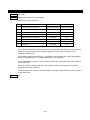
DPU-S445 SERIES THERMAL PRINTER TECHNICAL REFERENCE
Document Number U00110811305
First Edition
Second Edition
Third Edition
Forth Edition
Fifth Edition
Sixth Edition
May 2008
July 2008
January 2009
June 2009
February 2010
July 2011
Copyright © 2008-2011 by Seiko Instruments Inc.
All rights reserved.
Seiko Instruments Inc. (hereinafter referred to as “SII”) has prepared this technical reference for use by SII
personnel, licensees, and customers. The information contained herein is the property of SII and shall not be
reproduced in whole or in part without the prior written approval of SII.
SII reserves the right to make changes without notice to the specifications and materials contained herein and
shall not be responsible for any damages (including consequential) caused by reliance on the materials
presented, including but not limited to typographical, arithmetic, or listing errors.
is a trademark of Seiko Instruments Inc.
IrDA Protocol Stack 「μDeepCore(r)1.1」(C)ITX E-Globaledge Corp. All Rights Reserved.
ESC/P is trademarks of SEIKO EPSON CORPORATION.
BHT-Ir is trademarks of DENSO CORPORATION.
Bluetooth is registered trademarks of Bluetooth SIG, Inc.
TABLE OF CONTENTS
Section
Page
CHAPTER 1
TERMS USED IN THIS MANUAL
CHAPTER 2
SPECIFICATIONS
2.1
PRINTER SPECIFICATIONS............................................................................................. 2-1
2.2
SPECIFIED THERMAL PAPER SPECIFICATIONS.......................................................... 2-3
2.2.1 Timing Mark for the Cut Paper Dimensions .................................................................. 2-4
2.2.2 Thermal Label Paper Dimensions................................................................................. 2-6
2.3
SPECIFIED BATTERY PACK SPECIFICATIONS ............................................................. 2-8
2.4
PRECAUTIONS FOR USE................................................................................................. 2-9
CHAPTER 3
INTERFACE
3.1
SERIAL INTERFACE SPECIFICATIONS (RS-232C CONFORMITY) .............................. 3-1
3.2
USB INTERFACE SPECIFICATIONS................................................................................ 3-4
3.3
INFRARED INTERFACE SPECIFICATIONS..................................................................... 3-5
3.3.1 Physical Specifications.................................................................................................. 3-5
3.3.2 IrDA Specifications ........................................................................................................ 3-5
3.3.3 BHT-Ir Specifications..................................................................................................... 3-8
3.4
BLUETOOTH INTERFACE SPECIFICATIONS................................................................. 3-9
CHAPTER 4
FUNCTION SETTINGS
4.1
FUNCTION SETTING ........................................................................................................ 4-1
4.1.1 Function Settings(SWDIP1) .......................................................................................... 4-2
4.1.2 Function Settings(SWDIP2) .......................................................................................... 4-4
4.1.3 Function Settings(SWDIP3) .......................................................................................... 4-6
4.1.4 Function Settings(SWDIP4) .......................................................................................... 4-8
4.1.5 Function Settings by Switch Operation ....................................................................... 4-10
4.1.6 Function Settings by Commands ................................................................................ 4-13
4.2
TEST PRINT..................................................................................................................... 4-14
4.3
HEX DUMP MODE........................................................................................................... 4-15
5.1
5.2
5.3
5.4
CHAPTER 5
LAMP DISPLAY AND SWITCH FUNCTION
PRINTER STATE LAMP DISPLAY .................................................................................... 5-1
ERROR RECOVERY PROCEDURE ................................................................................. 5-2
POWER SWITCH............................................................................................................... 5-3
FEED SWITCH................................................................................................................... 5-3
CHAPTER 6
COMMAND DESCRIPTIONS
6.1
THE SUMMARY OF COMMAND FUNCTION ................................................................... 6-1
6.2
FUNCTION CODES ........................................................................................................... 6-5
6.3
CHARACTER CODES ....................................................................................................... 6-5
6.3.1 JIS Code System........................................................................................................... 6-5
6.3.2 Shift JIS Code System .................................................................................................. 6-7
6.4
MEMORY............................................................................................................................ 6-9
6.4.1 Extended RAM Memory ................................................................................................ 6-9
6.4.2 FLASH Memory ........................................................................................................... 6-16
iii
6.5
COMMAND DESCRIPTION ............................................................................................. 6-18
6.5.1 Command Format ....................................................................................................... 6-18
6.5.2 Formatting Commands................................................................................................ 6-19
6.5.3 Line Spacing Commands ............................................................................................ 6-23
6.5.4 Tab Setting Commands............................................................................................... 6-25
6.5.5 Print and Paper Feed Commands............................................................................... 6-27
6.5.6 Print Position Commands............................................................................................ 6-29
6.5.7 1-byte Character Set Selection Commands................................................................ 6-31
6.5.8 1-byte Characters Definition Commands .................................................................... 6-34
6.5.9 Character Decoration Commands............................................................................... 6-36
6.5.10 Character Pitch Adjustment Command....................................................................... 6-40
6.5.11 Kanji Character Set Selection Commands.................................................................. 6-43
6.5.12 Kanji Character Definition Commands ........................................................................ 6-45
6.5.13 Kanji Character Decoration Commands ..................................................................... 6-47
6.5.14 Kanji Character Pitch Adjustment Command.............................................................. 6-50
6.5.15 Image Command......................................................................................................... 6-53
6.5.16 Stamp .......................................................................................................................... 6-57
6.5.17 Other Commands ........................................................................................................ 6-61
6.5.18 Ruler Line Commands................................................................................................. 6-62
6.5.19 Optional Font Commands ........................................................................................... 6-66
6.5.20 Bar Code Commands.................................................................................................. 6-69
6.5.21 Routine Commands..................................................................................................... 6-83
6.5.22 Page Mode .................................................................................................................. 6-88
6.5.23 Status Commands....................................................................................................... 6-93
6.5.24 Character Set Command............................................................................................. 6-97
6.5.25 Auxiliary Function Commands .................................................................................... 6-99
6.5.26 Download Mode ........................................................................................................ 6-111
6.6
DEFAULTS ..................................................................................................................... 6-116
6.7
INITIAL AUTOMATIC STATUS TRANSMISSION ......................................................... 6-118
6.8
COMMAND INDEX......................................................................................................... 6-119
A.1
A.2
A.3
A.4
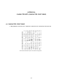
APPENDIX A
CHARACTER SETS (CHARACTER CODE TABLE)
CHARACTER CODE TABLE ............................................................................................. A-1
INTERNATIONAL CHARACTER SETS............................................................................. A-3
KANJI CODE TABLE.......................................................................................................... A-4
KANJI QUARTER SIZE CHARACTER SET ...................................................................... A-5
iv
Table
Page
TABLES
Table 1-1
Character Types and Relationship between 1-byte and 2-byte Characters ................ 1-1
Table 2-1
Table 2-2
Table 2-3
General Specifications ................................................................................................. 2-1
Thermal Paper Provided by SII .................................................................................... 2-3
Specified Thermal Paper Specifications ...................................................................... 2-3
Table 4-1
Table 4-2
Table 4-3
Table 4-4
Function Settings (SWDIP1) ........................................................................................ 4-2
Function Settings (SWDIP2) ........................................................................................ 4-4
Function Settings (SWDIP3) ........................................................................................ 4-6
Function Settings (SWDIP4) ........................................................................................ 4-8
Table 5-1 Printer Status Signals................................................................................................... 5-1
Table 5-2 Error Recovery Procedure ........................................................................................... 5-2
Table 6-1
Table 6-2
Table 6-3
Table 6-4
Table 6-5
Table 6-6
Table 6-7
Table 6-8
Table 6-9
Table 6-10
Command Summary .................................................................................................... 6-1
Memory Sizes Right After Initialization......................................................................... 6-9
Number of Bytes for Memory Control Information ....................................................... 6-9
Commands for Allocating or Freeing Memory Area................................................... 6-10
GS 'p' 0 Used Memory Capacity of PDF417 Print Command.................................... 6-11
GS 'p' 1 Used Memory Capacity of QR Code Print Command .................................. 6-12
GS 'p' 2 Used Memory Capacity of Data Matrix Print ................................................ 6-13
Data Matrix Symbol Sizes .......................................................................................... 6-14
GS 'p' 3 Used Memory Capacity of MaxiCode Print .................................................. 6-15
Default Settings ...................................................................................................... 6-116
v
Figure
Page
FIGURES
Figure 1-1
Figure 1-2
Figure 1-3
Relationship between Input Buffer and Line Buffer .................................................... 1-1
Line Spacing ............................................................................................................... 1-2
Character Spacing ...................................................................................................... 1-2
Figure 2-1
Figure 2-2
Figure 2-3
Figure 2-4
Dimensions ................................................................................................................. 2-2
Timing Mark for the Cut Paper (back surface)............................................................ 2-4
Example for the Cut Paper.......................................................................................... 2-5
Example for Thermal Label Paper Dimensions .......................................................... 2-6
Figure 6-1
Figure 6-2
Figure 6-3
Figure 6-4
Figure 6-5
Figure 6-6
Figure 6-7
Figure 6-8
Figure 6-9
Figure 6-10
Figure 6-11
Figure 6-12
Figure 6-13
Figure 6-14
Figure 6-15
Figure 6-16
Figure 6-17
Figure 6-18
Figure 6-19
Figure 6-20
Figure 6-21
Figure 6-22
Figure 6-23
Figure 6-24
Figure 6-25
Figure 6-26
Figure 6-27
Figure 6-28
Figure 6-29
Figure 6-30
Figure 6-31
Figure 6-32
Figure 6-33
Figure 6-34
Figure 6-35
Figure 6-36
Figure 6-37
Figure 6-38
Program Sample 1 .................................................................................................... 6-22
Print Sample 1........................................................................................................... 6-22
Program Sample 2 .................................................................................................... 6-24
Print Sample 2........................................................................................................... 6-24
Program Sample 3 .................................................................................................... 6-30
Print Sample 3........................................................................................................... 6-30
Program Sample 4 .................................................................................................... 6-33
Print Sample 4........................................................................................................... 6-33
Program Sample 5 .................................................................................................... 6-41
Print Sample 5......................................................................................................... 6-42
Program Sample 6 .................................................................................................. 6-51
Print Sample 6......................................................................................................... 6-52
Program Sample 7 .................................................................................................. 6-56
Print Sample 7......................................................................................................... 6-56
Program Sample 8 .................................................................................................. 6-60
Print Sample 8......................................................................................................... 6-60
Program Sample 9 .................................................................................................. 6-61
Print Sample 9......................................................................................................... 6-61
Program Sample 10 ................................................................................................ 6-65
Print Sample 10....................................................................................................... 6-65
Program Sample 11 ................................................................................................ 6-68
Print Sample 11....................................................................................................... 6-68
Program Sample 12 ................................................................................................ 6-77
Print Sample 12....................................................................................................... 6-78
Program Sample 13 ................................................................................................ 6-79
Print Sample 13....................................................................................................... 6-80
Program Sample 14 ................................................................................................ 6-81
Print Sample 14....................................................................................................... 6-82
Program Sample 15 ................................................................................................ 6-87
Print Sample 15....................................................................................................... 6-87
Program Sample 16 ................................................................................................ 6-92
Print Sample 16....................................................................................................... 6-92
Program Sample 17 ................................................................................................ 6-96
Print Sample 17....................................................................................................... 6-96
Program Sample 18 ................................................................................................ 6-98
Print Sample 18....................................................................................................... 6-98
Program Sample 19 .............................................................................................. 6-106
Print Sample 19..................................................................................................... 6-106
vi
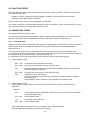
CHAPTER 1
TERMS USED IN THIS MANUAL
This chapter describes the terms used in this manual.
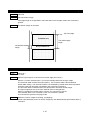
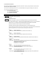
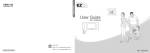
INPUT BUFFER AND LINE BUFFER
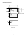
When the DPU-S445 (hereinafter it is referred to as “printer”) receives data (character codes and
commands) from the host devices, it stores the data in the printer input buffer. The input buffer has
a capacity of 4K bytes (4096 bytes). Then, the printer retrieves data from the input buffer. If data is
character code, data is stored into the line buffer. If data is command, data is executed as
command immediately.
The printer inputs character codes to the line buffer until the amount of character codes reaches
the amount to be printed on one line, then prints the characters. The printer repeats this operation
to print all the character data.
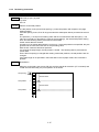
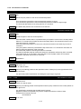
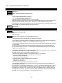
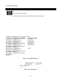
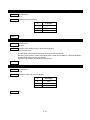
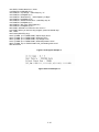
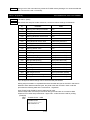
The relationship between the input buffer and line buffer is illustrated in Figure 1-1.
Host Device
Input Buffer
Line Buffer Print Operation
One Line of Characters
is Printed.
Figure 1-1 Relationship between Input Buffer and Line Buffer
1-byte characters and 2-byte characters
The printer can print two-size characters; 1-byte characters and 2-byte characters.
Table 1-1 lists the character types which can be printed by 1-byte and 2-byte characters.
Table 1-1 Character Types and Relationship between 1-byte and 2-byte Characters
Character Types
1-byte characters
Katakana character (ANK)
Extended graphics character (IBM Compatible)
Codepage 1252
2-byte characters
Kanji, User-defined characters
*1 The size of a character to be printed differs depending on the font specified. (See 2.1 Printer Specifications.)
1-1
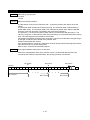
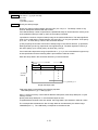
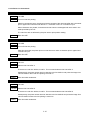
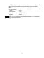
Line Spacing
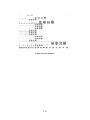
Line spacing is the space between the lines of printed characters (See Figure 1-2).
ABC
Line Spacing
ABC
Figure 1-2 Line Spacing
This printer use a line thermal print mechanism, therefore, a paper feed step is necessary before
printing characters or bit images.
The line feed command with printing feeds the paper for height of characters or bit images.
Therefore, a paper feed amount which is smaller than character or bit image height is ignored.
Printing with underline feeds the paper 4 dot lines in addition to the character height.
Line feeding without printing feeds the paper for specified line feed amount.
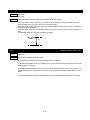
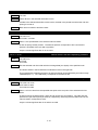
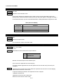
Character Spacing
Character spacing is the space between each character in the horizontal direction (See Figure
1-3).
A
B
Character Spacing
Figure 1-3 Character Spacing
Line
The word “line” in this manual indicates a line of characters. For example, the sentence “the printer
feeds paper one line” indicates that the printer feeds paper a line of characters.
Dot Line
The words “dot line” in this manual indicate a line of dots in the vertical direction. For example, the
sentence “the printer feeds paper by one dot line” indicates that the printer feeds paper by the
space of 1 dot.
Paper Auto-loading
The paper auto-loading function which can loads the cut paper from the paper slot automatically by
using the paper feed motor.
Notation in the Technical Reference
Hexadecimal
Hexadecimal is showing as follows;
Example: 0AH (a hexadecimal unit 'H' is added behind a hexadecimal number.)
Character string
A character string is showing as follows;
Example: 'G' (a character string 'G' is enclosed with a single quotation mark.)
1-2
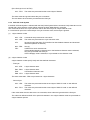
CHAPTER 2
SPECIFICATIONS
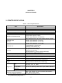
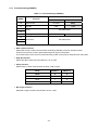
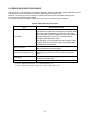
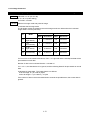
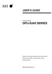
2.1 PRINTER SPECIFICATIONS
Table 2-1 General Specifications
Item
Total number of dots
Effective dot number
Resolution
Printing width / paper width
Printing speed
Number of character per line
Character size
(H x W)
Character set
Interface
Input buffer size
Dimensions (W x D x H)
Mass
Operating temperature and humidity
range
Storage temperature and humidity
range
EMC
Regulations
The wireless telegraph
law regulation
conformity
Safety
Countries under the regulations
Specification
832 dots/line
832 dots/line
W 8 dots/mm x H 8 dots/mm
104 / 112 mm
90 mm/s max. *1
24 dots 1-byte characters: 52 characters
(right character space is 4 dots)
24 dots 2-byte characters: 26 characters
(left character space is 0 dot, right character space is 8 dots)
24 dots 1-byte characters: 24 x 12 dots
16 dots 1-byte characters: 16 x 8 dots
24 dots 2-byte characters: 24 x 24 dots
16 dots 2-byte characters: 16 x 16 dots
Katakana character set *2
Extended graphics character set
Codepage 1252 character set
JIS 1st and 2nd level of Kanji *2
Serial (RS-232C conformity)
USB (Ver.2.0 conformity)
Infrared (IrDA Ver.1.2 / BHT-Ir protocol conformity)
Bluetooth (Ver.2.0+EDR conformity) *3
4K bytes
145 mm x 135mm x 8mm
Approx. 490 g (including the battery pack, excluding paper)
Temperature: 0 to 50°C
Humidity: 30%RH to 80%RH (Non condensing)
Temperature: -25 to 60°C
Humidity: 5%RH to 90%RH (Non condensing)
VCCI Class B, FCC Class B, Industry Canada Class B,
CE (EMC), CCC, KC, BSMI
FCC, IC, CE (R&TTE), Radio Law of Japan, SRRC, ANATEL
CB, CE (LVD), CCC, BSMI
Japan, USA, Canada, EU, EFTA, Australia, New Zealand,
China, Korea, Taiwan, Brazil
*1: Using AC adapter, printing ratio is 7.5% or lower, thermal head temperature is 25°C.
*2: SII Japanese font set installed (at shipping).
*3: Only for Bluetooth-supporting model.
2-1
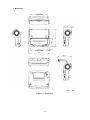
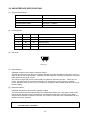
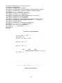
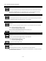
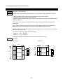
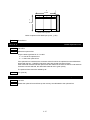
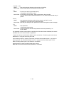
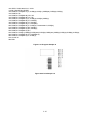
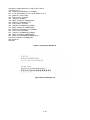
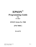
Dimensions
Paper Inlet
Paper Outlet
Unit
Figure 2-1 Dimensions
2-2
:
mm
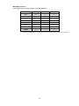
2.2 SPECIFIED THERMAL PAPER SPECIFICATIONS
Table 2-2 Thermal Paper Provided by SII
Item
Specifications
Model
TP-341L-1
Type
Normal paper roll
Paper width
112
Outside diameter
48mm max.
Paper thickness
59 ±5 μm
Printing surface of Paper roll
Outside
0
-1.0
mm
Table 2-3 Specified Thermal Paper Specifications
Item
Paper roll
Paper mode *1
Cut paper
Label paper
Specifications
PD160R-N
Oji Paper Co., Ltd.
TF50KS-E2D
Nippon Paper Industries Co.
P350
Kanzaki Specialty Papers
KT55F20
Papierfabrik August Koehler AG
TC98KS-LH
Nippon Paper Industries Co.
TF8067
Mitsubishi Hi-Tech Paper
TL69KS-HW76B
Nippon Paper Industries Co.
0
-1.0
Paper width
112
mm
Outside diameter
50 mm max.
Inside diameter
8 mm min. (Label paper: Outside diameter of paper core should be
25.4 mm min.)
Spectral reflectivity
Black, near-infrared reflectance should be 6% and below.
Printing surface of Paper roll
Outside
*1 Use each specified thermal paper in an applicable thermal paper mode.
2-3
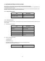
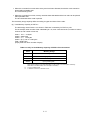
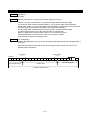
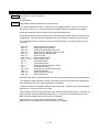
2.2.1 Timing Mark for the Cut Paper Dimensions
112
0
-1.0
9 min.
16
5
Insertion direction of paper
3 max.
Unit
Figure 2-2 Timing Mark for the Cut Paper (back surface)
2-4
:
mm
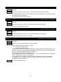
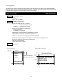
(1) Example of use of the cut paper
An example of use of the cut paper is shown Figure 2-2.
(a) Set the function setting of Paper Mode to “Cut paper”.
(b) Set the paper length as page length.
(c) Insert the cut paper.
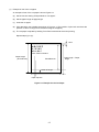
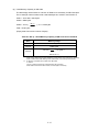
(d) Print data within the printable area shown in Figure 2-3. (The position of print end must be at the
position of 15mm or longer from the bottom edge of the paper.)
(e) The cut paper is ejected by sending Form Feed command at the end of printing.
Repeat steps (c) to (e).
6mm
ABCDEF
012345
abcdef
Form Feed command
Paper length
(90 to297mm)
Printable area
15mm or longer
Paper ejection
Figure 2-3 Example for the Cut Paper
2-5
Page length Paper
length
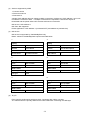
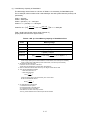
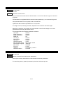
2.2.2 Thermal Label Paper Dimensions
112
0
-1.0
110
6
8
20 to 250
ABCDEF
012345
abcdef
Page length
Label length
Form Feed command
To the beginning of the next label
3
Non-printing area
b. Paper cut position
Printing area
a. Print start position
ABCDEF
012345
abcdef
Thermal label paper (surface)
12
3 max.
5
9 min.
Backing (back surface)
Unit
Figure 2-4 Example for Thermal Label Paper Dimensions
2-6
:
mm
(1) Example of use of thermal label paper
An example of use of the thermal label paper is shown Figure 2-4.
(a) Set the function setting of Paper Mode to “Mark Roll Paper”.
(b) Insert the thermal label paper.
(c) Set the page length as the length from the beginning of the current label to the beginning of the
next label.
(d) Set the skip amount (non-printing area) between labels.
(e) Print data within the printable area.
(f)
Use Form Feed command to find the beginning of the next label. The mark on the next label is
detected and the beginning of the next label is located by sending Form Feed command.
The print start position after the beginning of the next label is placed at position 'a', and the paper
cut position is 'b' as shown in Figure 2-4.
Repeat steps (e) to (f).
(NOTE) When Mark Position Correct of SWDIP 4-5 is set as Enable, the printer operates
paper feeding to backward 5 mm just before printing process after placing print
start position.
If this function set as Enable, use the thermal label paper 40mm or longer length to
prevent paper jamming from feeding paper backward.
2-7
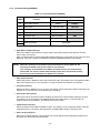
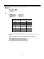
2.3 SPECIFIED BATTERY PACK SPECIFICATIONS
Item
Specification
Model
BP-L0720-A1-E
Available printing lines
Battery Cycle Life
*2
*1
10000 lines min.
300 cycles
*1: 25C, character spacing is 4 dots, line spacing is 34 dots, TF50KS-E2D selection, print density is 100%, continuous printing
with 'H' 1-byte characters, serial communication, fully charged with 8.4 V by specified battery charger.
*2: 25C, charged in the printer with specified AC adapter, print ratio is 12.5%, charged with 70%* or more of fully charged.
* The rate in environment of 0 to 50C becomes 40% or more.
2-8
2.4 PRECAUTIONS FOR USE
Always print the two-dimensional bar code and ladder bar code (its bar is to be printed verticality to
the printer) within 0 to 40°C to ensure the bar code's reading accuracy.
The two-dimensional bar code and ladder bar code printing always requires the low speed mode to
ensure its reading accuracy. Set the print speed to the low speed mode by using Motor Speed
Select (GS 'E') command.
The height of the ladder bar code requires over 10 mm to ensure its reading accuracy.
To print data at a temperature of 15°C or lower, be sure to set data for black printing to 78 mm or
less (see figure below).
At a low temperature, the total number of black printing areas (w1 + w2 in the figure above, for example)
should not exceed 78mm for parts having high printed ratios* (including the ladder bar code part).
Be aware, in particular, that reverse printing and ruled line tend to increase the ratio.
* Parts where many black dots are used when viewed in the direction vertical to the paper feed direction.
Use of the battery pack at low temperature will run out of power in a shorter time.
When printing ruled lines, a 2-dot configuration is needed. In case of a 1-dot configuration, the
printed lines may be invisible.
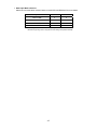
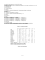
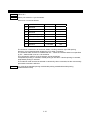
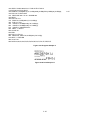
Always use the printer within the shadowed range depicted in figure below Relationship between
Temperature and Humidity.
[% RH]
90
40°C, 80%RH
80
Humidity
70
60
50°C, 47%RH
50
40
30
20
10
0
10
20
30
Temperature
2-9
40
50
[°C]
When using a Bluetooth interface, the radio environment around the printer may cause a failure in
communications. This is due to the specifications of Bluetooth, which is a radio communications
standard.
When handling this product, be aware of static electricity. If the static electricity is discharged, this
could case communication failure. When this problem occurs, disconnect the USB connector that
is connected to the host device and wait few seconds before connect it again.
When the printer is left unused for a long period of time, a white powder appears to the surface of
platen. (This is the powder by which an ingredient of a thermal paper was recrystallized.)
If the powder appears to the platen, wipe the platen with ethanol and use the printer after ethanol
has dried completely.
Also, make sure not to adhere ethanol except the platen area. If ethanol adheres except the platen
area, wipe it off immediately.
(NOTE) Refer to "SAFETY PRECAUTIONS" and "OPERATING PRECAUTIONS" on DPUS445 SERIES USER'S GUIDE which be included with the printer for other
precautions.
2-10
CHAPTER 3
INTERFACE
This chapter describes 4 types of the interface specifications which are required to connect the host device
with the printer.
Irrespective of the interface used, amount of the input buffer in the printer is 4k bytes, and transmission
buffer is 768 bytes. If the transmission buffer becomes the condition of the buffer full, the printer waits data
processing until the buffer can be received data. Be aware that printing process does not performed in that
meantime.
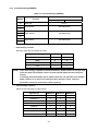
3.1 SERIAL INTERFACE SPECIFICATIONS (RS-232C CONFORMITY)
(1) General specifications
Item
Specification
Synchronization
Asynchronous
Signal level
MARK = –3.0 to –15.0 V: Logic '1'
SPACE= +3.0 to +15.0 V: Logic '0'
Baud rate
1200, 2400, 4800, 9600, 19200, 38400, 57600, 115200 bps
Data bit length
7 bits or 8 bits
Stop bit length
1 bit or 2 bits
Parity
None, odd or even
Reset
Break signal input to RxD (20ms or longer)
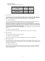
(2) Pin assignment
Pin No.
Name
I/O
Function
1
N.C.
-
No connection
2
TxD
O
Sends data from the printer to the host device.
3
RxD
I
Receives data from the host device.
Break signal input (SPACE) resets the printer.
4
-
-
Internally connected with pin No.6.
5
GND
-
Signal ground
6
-
-
Internally connected with pin No.4.
7
CTS
I
Outputs SPACE when the host device can receive data.
8
RTS
O
Outputs SPACE when the printer can receive data.
3-1
(3) Connector
8
1
3260-8S3: HIROSE ELECTRIC CO., LTD. or equivalent
(4) Examples of connection with the host device (a standard personal computer)
Printer
Host device
Printer
Host device
N.C.
1
1
F.G
N.C.
1
TXD
2
2
TXD
TXD
2
2
RXD
3
3
RXD
RXD
3
3
TXD
DSR
4
4
RTS
DSR
4
4
DTR
GND
5
5
CTS
GND
5
5
S.G
DTR
6
6
DSR
DTR
6
6
DSR
CTS
7
7
S.G
CTS
7
7
RTS
RTS
8
20 DTR
RTS
8
8
CTS
SHELL
SHELL
SHELL
(Shield)
8-pin – 25-pin
(Shield)
RXD
SHELL
8-pin – 9-pin
(5) Data reception
Busy control
In Busy Control, RTS outputs MARK until the printer is ready to receive data after power ON.
After the printer is ready, RTS outputs SPACE and the received data is input to the input buffer.
When there are 33 bytes or less remaining in the input buffer, RTS outputs MARK. The host
device does not transmit data during RTS outputs MARK. When the input buffer is ready to
receive data (there are 65 bytes or more in the input buffer) after stopping data reception, RTS
once again outputs SPACE. If an error occurs in the printer, RTS outputs MARK and inhibits data
entry until the error is cleared. If an error is cleared, RTS outputs SPACE again.
For RTS output when an error occurs, the setting is changed by Busy Output When Error Occurs at
function setting.
Xon/Xoff control
In Xon/Xoff control, TXD outputs Xon code (11H) from power ON until the printer is ready to receive
data. Received data is input to the input buffer. When there are 65 bytes or less remaining in
the input buffer, TXD outputs Xoff code (13H). The host device does not transmit data while Xoff
code is received. When the input buffer is ready to receive data (there are 129 bytes or more in
the input buffer) after stopping data reception, TXD once again outputs Xon code. When this
control method is selected, the RTS signal always outputs SPACE. If an error occurs in the printer,
TXD outputs Xoff code and inhibits data entry until the error is cleared. When the error is cleared,
TXD outputs Xon code again.
For Xoff code transmission when an error occurs, the setting is changed by Busy Output When
Error Occurs at function setting.
Data reception error in serial communication
When Parity is selected as Yes by the function setting, a '!' is printed next to data in which a parity
error occurred and a '?' is printed next to data in which any other error (framing error, etc.) occurred.
If a serial data reception error occurs, no error indication other than the printing of '!' and '?' is
performed (for example, the ERROR lamp does not light).
3-2
(6) Data transmission
Busy control
In Busy Control, the conditions which transmit status information to the host device from the printer
are as follows;
When CTS Control of function setting sets to Enable, the printer sends data from TXD after
confirming CTS status as SPACE.
When CTS Control of function setting sets to Disable, the printer sends data from TXD regardless
of the condition of the host device.
Xon/Xoff control
In Xon/Xoff control, the conditions which transmit status information to the host device from the
printer is that the printer sends data from TXD regardless of the condition of the host device.
(NOTE) Be aware that if the transmission buffer becomes full, the printer does not print
until the buffer is available.
3-3
3.2 USB INTERFACE SPECIFICATIONS
(1) General specifications
Item
Specification
USB Version
Ver 2.0 conformity
USB Printing class specification
1.1
Communication speed
Full speed(12 Mbps)
Communication protocol
Bulk transfer
(2) Pin assignment
Pin No.
Name
I/O
Function
1
Vbus
-
2
D-
I/O
USB data signal
3
D+
I/O
USB data signal
4
N.C.
-
No connection
5
GND
-
GND
USB power supply
(3) Connector
5
1
Mini B type
(4) Data reception
USB data reception uses a bulk-out transfer method.
The data are received even during the printing operation, and when the data accumulate in the input
buffer by the amount of input buffer + 2 packets, the NAK response continues until amount of the input
buffer becomes 129 bytes or more.
The number of bytes that can be received with one packet is maximum 64 bytes. When an error
occurs, the NAK response continues until the error is cleared after receiving data of 2 packets.
For the operation when an error occurs, the setting is changed by Busy Output When Error Occurs at
function setting.
(5) Data transmission
USB data transmission uses a bulk-in transfer method.
The response data are stored temporarily in the transmission buffer, and a response is made to the
bulk-in packet request from the host device. If no transmission data exist, the zero length data is
returned when the bulk-in request is received. The number of bytes that can be transmitted with one
packet is maximum 64 bytes.
(NOTE) Be aware that if the transmission buffer becomes full, the printer does not print
until the buffer is available.
3-4
3.3 INFRARED INTERFACE SPECIFICATIONS
The printer can communicate with the host device through the infrared interface.
The infrared interface used in the printer conforms to the physical layer standard (Ver 1.2) specified by the
Infrared Data Association (IrDA).
The printer supports the minimum infrared transmission functions as the second station specified by IrDA
and BHT-Ir protocol specified by DENSO CORPORATION.
3.3.1 Physical Specifications
Item
Specification
Transmission distance
0.2m max.
Transmission range
15°
Infrared transmission pulse width Typ. 1.63 s
3.3.2 IrDA Specifications
The printer conforms to IrDA Ver.1.2 and supports only the minimum infrared transmission functions as the
second station.
(1) Transmission specifications
Item
Specification
Baud Rate
9600 to 115200 bps
Data Size
64 to 512 bytes
Window Size
1
Additional BOFs
0 to 48
Maximum Turn Around Time
500ms
Minimum Turn Around Time
10ms
Link Disconnect/Threshold Time
3 to 40 s
(2) Services supported by IrLAP
1. Connect service
2. Data service
3. Disconnect service
IrLAP does not support a transfer for non-number and sniffing services.
The printer does not initiate connections.
Service Hint
Printer, IrCOMM
Device Nickname
DPU-S445
3-5
(3) Services supported by IrLMP
1. Connect service
2. Disconnect service
3. Data service
A single LSAP address does not support multiple connections. furthermore, LSAP address 7 and 9 can
not share the connection state. If multiple connections are requested, a disconnect request is
transmitted and the printer waits until it receives a disconnect command.
IAS server: LSAP address 0
IAS client: Not supported
Printer application: LSAP address 7 (3-wireraw/IrLPT) and address 9 (3-wire/9-wire)
(4) IAS service
IAS service is supported by 'GetValueByClass' only.
Return values for GetValueByClass inquiries are listed below.
1.
4.
Inquiry
Inquiry
Class
Device
Class
IrLPT
Attribute
Device Name
Attribute
IrDA:IrLMP:LsapSel
Return value
Device Name
Return value
Sll Thermal Printer
Lsap address
2.
7
5.
Inquiry
Class
IrDA:IrCOMM
Class
IrDA:IrLMP
Attribute
Parameters
Attribute
IrDA:IrLMP:LsapSel
Return value
Return value
Service type
3-Wireraw
Port type
Serial
Lsap address
3
6.
Inquiry
Inquiry
7
Class
IrDA:IrCOMM
Class
IrDA:IrCOMM
Attribute
IrDA:IrLMP:LsapSel
Attribute
IrDA:TinyTP:LsapSel
Return value
Lsap address
Return value
7
Lsap address
9
(5) TinyTP
Flow control is performed by this layer when connecting with 3-Wire or 9-Wire.
'5' is transferred to the primary station as the initial credit when connecting the LMP layer.
3-6
(6) IrCOMM
Supports 3-Wireraw, IrLPT, 3-Wire and 9-Wire.
Flow control is performed only by the IrLAP layer when connecting with 3-Wireraw or LrLPT.
Flow control is performed by the TinyTP layer when connecting with 3-Wire or 9-Wire.
Xon/off control and line status control are not supported.
(7) Command response processing during IrDA transmission
If the printer receives a command that requires transmission of data from the remote station during IrDA
transmission, and then stores the data in the transmission buffer and transfers them at transmit timing to
the remote station.
The printer clears a response data in the transmission buffer when transmission to the remote station is
disconnected for busy state. When the remote station is in disconnection, the printer does not store the
data in the transmission buffer and the data is cleared.
However the printer transfers the status regardless of the remote station state when initial automatic
status transmission is enabled.
The printer transfers status when the remote station is connected again if automatic status transmission
has not deactivated by power off.
(NOTE) Be aware that if the transmission buffer becomes full, the printer does not print
until the buffer is available.
3-7
3.3.3 BHT-Ir Specifications
The printer also supports BHT-Ir communication specified by DENSO CORPORATION.
The printer can receive data from the 'BHT-6500' made by DENSO CORPORATION when Data Input Mode
SWDIP2-1 and SWDIP2-2 is selected to BHT-Ir.
The inherent processing of the printer for BHT-Ir communication is shown below:
See BHT-Ir protocol specification for details of the protocol.
(1) ID
Printer ID:
3445H (fixed)
(2) Text format
Only text is valid.
Files with 'PD3', 'FN3' or 'EX3' extension can not be processed.
(3) Input buffer full processing when receiving header.
Upon receiving the header, the printer inhibits connection with the host device when the remaining
amount of the input buffer becomes 512 bytes or less after subtracting the field number of the data text
indicated in heading text.
(4) Input buffer full processing when receiving data
Upon receiving data, the printer sends WACK supervisory sequence to a host device for requiring
temporarily delay of the data output from the host device as the input buffer full state when the
remaining amount of the input buffer is 255 bytes or less.
Then, the printer sends the ACK supervisory sequence to the host device to restart data transmission
when the remaining amount of the input buffer is 512 bytes or more.
The printer transfers the EOT supervisory sequence and stops when the input buffer full status
continues more than 1 minute.
(5) Command response processing during BHT-Ir transmission
No response command is transferred in BHT-Ir transmission mode.
Although response data is generated, it is discarded.
3-8
3.4 BLUETOOTH INTERFACE SPECIFICATIONS
Bluetooth-supporting model can perform wireless communication by Bluetooth communication function.
When Data Input Mode of the function setting is set to Bluetooth/USB, internal Bluetooth module of the
printer operates regardless of its communication.
When using the printer at the place with radio limitations like a hospital or an airplane, set Data Input Mode
of the function setting as Serial/USB or IrDA/USB to stop Bluetooth communication.
(1) General specifications
Item
Bluetooth version
Specification
2.0+EDR conformity
Transmitted electric power class Class 2
Connection mode
Peer-to-peer
Profile
SPP
PIN code
*1
Device name
None (default)
*1
DPU-S445 (default)
*1: This specification can be changed by the command.
(2) Security
The printer does not set with PIN code or the Link Key in default. Bluetooth device uses security mode 1,
so no encryption is used.
Bluetooth device becomes security mode 3 if PIN code is set by Set default/Set test print header
command or Bluetooth Link Key selection of the function setting is set to Enable, and encryption is used.
When the setting of Bluetooth Link Key is Disable and selection of PIN code is canceled, Bluetooth
device becomes security mode 1 again, and no encryption is used.
(3) Input buffer
Capacity of input buffer for internal Bluetooth module is 3Kbytes. Received data is stored in the input
buffer of Bluetooth module, and then these data is to be processed after data transfer to input buffer of
the printer.
If an error occurs, the printer stops receiving data after data that stored into input buffer of Bluetooth
until the error is cleared.
For the operation when an error occurs, the setting is changed by Busy Output When Error Occurs at
function setting.
(NOTE) Be aware that if the transmission buffer becomes full, the printer does not print
until the buffer is available.
(4) Link key saving
If the Bluetooth Link Key selection of the function setting is set to Enable, the printer saves the link key
to connect with the host device in the pairing process.
The host devices can be saved up to 10. When requiring to save the 11th host device, perform the
pairing after clearing the saved host devices in the printer.
To clear the all of saved host device data, set the Bluetooth Link Key selection of the function setting as
Disable after setting Data Input Mode of the function setting as Bluetooth. The printer clears the stored
host device data after the above process.
3-9
CHAPTER 4
FUNCTION SETTINGS
4.1 FUNCTION SETTING
The communication method, a paper types, and so on can be preset in this printer.
Preset these functions before using the printer.
The function settings of the printer are stored in FLASH memory. Once these are set, these are stored until
changing again.
The function settings are specified through the software DIP switch (hereinafter referred to as SWDIP
switch), SWDIP1 to 4.
Details for settings of SWDIP 1 to 4 are described below. The value that is indicated by boldface and shaded
cell shows a default setting value. The words in parentheses in the table are indicated in test print.
4-1
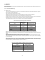
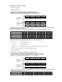
4.1.1 Function Settings(SWDIP1)
Table 4-1 Function Settings (SWDIP1)
SWDIP
1-8
Data Control
1-7
Stop Bit
1-6
1-5
1-4
Value
Function
0
1
Xon/Xoff
Busy
2 bits
1 bit
Parity
See table below
Bit Length
7 bits
8 bits
1-3
1-2
Baud Rate
See table below
1-1
Data Control selection
Select flow control in serial communication as BUSY (hardware) control or Xon/Xoff control.
In BUSY control, flow control is performed using RTS signal in the printer.
In Xon/Xoff control, flow control is performed using codes of Xon(11H) or Xoff(13H) from the printer.
Stop Bit selection
Select Stop Bit in serial communication as 1 bit or 2 bits.
Parity selection
Select Parity in serial communication as Even, Odd or None.
Parity
SWDIP1-6
SWDIP1-5
None
0
0
Odd
0
1
None
1
0
Even
1
1
Bit Length selection
Select Bit Length in serial communication as 8 or 7 bits.
4-2
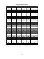
Baud Rate selection
Select Baud Rate of communications as Serial and BHT-Ir.
Baud Rate
SWDIP1-3
SWDIP1-2
SWDIP1-1
1200 *1
0
0
0
2400
0
0
1
0
1
0
9600
0
1
1
19200
1
0
0
38400
1
0
1
57600
1
1
0
115200
1
1
1
4800
*1
*1 This setting is enabled only when Serial is selected as the communication mode.
When BHT-Ir is selected as the communication mode, the baud rate is set to 2400 bps automatically.
4-3
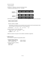
4.1.2 Function Settings(SWDIP2)
Table 4-2 Function Settings (SWDIP2)
SWDIP
Value
Function
0
1
Enable
Disable
Shift-JIS Code
JIS Code
2-8
Auto Status Output
2-7
Kanji Code
2-6
Font Size
16 dots
24 dots
2-5
Auto Power Off
Enable
Disable
2-4
Character Set
IBM Compatible
ANK
2-3
Auto Loading
Disable
Enable
2-2
2-1
Data Input Mode
See below
Auto Status Output selection
When Auto Status Output selection sets to Enable, the printer sends printer status to the host
device every one second.
Refer to the descriptions of Automatic Status Response (DC2 'e') command for the code to be sent.
Moreover, refer to 6.7 INITIAL AUTOMATIC STATUS TRANSMISSION for more details.
(NOTE) When this function set to Enable, the printer keeps on storing data into the
transmission buffer if the printer status is not received.
The condition of the transmission buffer as buffer full may not work because
status data can not be created. Note that the printer does not perform printing
processing until the transmission buffer full is cleared.
Kanji Code selection
Select Kanji Code in default as JIS Code or Shift-JIS Code. This setting can be changed by Select
Kanji Code System (FS 'C') command (6.5.11 Kanji Character Set Selection commands).
Font Size selection
Select Font Size in default as 16 or 24 dots. This setting can be changed by Select Character Font
Size (DC2 'F') command (6.5.24 Character Set Command).
Auto Power Off selection
When Auto Power Off selection sets to Enable, the printer turns itself off after passing a set time.
This setting can be changed by Set default/Set test print header (DC2 'i') command (6.5.25
Auxiliary Function Commands). The default value is 30 minutes.
Character Set selection
Select Character Set as IBM compatible or ANK. This setting can be changed by Select character
code table (ESC 't') command. See Appendix A CHARACTER CODE for character code.
Auto Loading selection
When Auto Loading selection sets to Enable, the printer detects the thermal paper inserted from
the paper slot and loads that automatically.
4-4
Data Input Mode selection
Select the communication method. Refer to CHAPTER 3 INTERFACE for more detail.
Data Input Mode
SWDIP2-2
SWDIP2-1
BHT-Ir/USB
0
0
Serial/USB
0
1
1
0
1
1
IrDA/USB
Bluetooth/USB
*1
*1 This setting is enabled for Bluetooth-supporting model only.
Bluetooth-supporting model is shipped with this setting value (Bluetooth/USB).
4-5
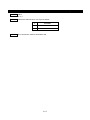
4.1.3 Function Settings(SWDIP3)
Table 4-3 Function Settings (SWDIP3)
SWDIP
3-8
3-7
3-6
Value
Function
0
1
Reserved
Fix to 1
Print Density
See table below
Paper Select
See table below
Paper Mode
See table below
3-5
3-4
3-3
3-2
3-1
Print Density selection
Normally, select the print density as 100%.
Print Density
SWDIP3-7
SWDIP3-6
95%
0
0
100%
0
1
105%
1
0
110%
1
1
(NOTE) If too much energy is applied to the thermal head, it would shorten its life span and
cause the paper feed problem. Set an accurate thermal paper selection and print
density.
If selecting the thermal paper that is different from the one specified in the thermal
paper selection or in case of not setting the print density in 100%, verify the
performance with your actual device before printing.
Thermal Paper selection
Select the thermal paper by Paper Select.
Paper Select
SWDIP3-5
SWDIP3-4
SWDIP3-3
PD160R-N
0
0
0
TC98KS-LH
0
0
1
P350
0
1
0
Reserved
0
1
1
KT55F20
1
0
0
TF8067
1
0
1
TL69KS-HW76B
1
1
0
TF50KS-E2D (TP-341L-1)
1
1
1
4-6
Paper Mode selection
Select Paper Mode as the thermal paper in use.
Paper Mode
SWDIP3-2
SWDIP3-1
Cut Paper
0
0
Roll Paper
0
1
Mark Roll Paper
1
0
Reserved
1
1
(1) Cut Paper mode
This mode assumes that to print the thermal paper which be cut by a certain fixed length. The paper
should be printed the mark on back side to detect paper position when loading the paper automatically.
Refer to 2.2 SPECIFIED THERMAL PAPER SPECIFICATION for the paper dimensions.
(a) Auto loading operation
In this mode, the printer feeds the thermal paper to the set value by detecting the paper mark after
loading the thermal paper from the paper slot, and then becomes print-ready status.
When the mark for detection is not printed on the back side, the printer stops as an error status after
feeding the thermal paper up to paper length which is set. At this time, the printer is in the state waiting
for error release by pressing the FEED switch. When the FEED switch is pressed, the thermal paper is
fed one dot line and the printer goes print-ready status.
Amount of paper feed can be set by Set Default/Set Test Print Header (DC2 'i') command. The default
is 50 mm.
(b) Process of out-of-paper detection
The printer processes the error operation by lighting the lamp if out-of-paper error detected.
(2) Roll Paper mode
This mode assumes that to print the thermal paper roll.
(a) Process of out-of-paper detection
The printer processes the error operation by lighting the lamp if out-of-paper error detected.
(3) Mark Roll Paper mode
This mode assumes that to print the thermal paper roll with the printed mark at regular intervals on the
back side which to detect paper position. Refer to 2.2 SPECIFIED THERMAL PAPER SPECIFICATION
for the paper roll dimensions.
(a) Operation of paper detection
In this mode, the printer determines the status as the out-of-paper error by feeding the thermal paper
10mm or longer, if it is less than 10mm, the printer determines the status as the mark and does not
detect the out-of-paper error.
4-7
4.1.4
Function Settings(SWDIP4)
Table 4-4 Function Settings (SWDIP4)
SWDIP
Value
Function
0
1
Enable
Disable
4-8
Bluetooth Link Key Selection
(Bluetooth Link Key)
4-7
Reserved
4-6
Busy Output When Error
Occurs (Error)
Unbusy
Busy
4-5
Mark Position Correct
Enable
Disable
4-4
4-3
Fix to 1
Bluetooth Baud Rate
See below
4-2
CTS Control
Enable
Disable
4-1
Auto Activation by AC
Enable
Disable
Bluetooth Link Key Selection
This function is set to Enable, the printer saves the link key from the host device to connect in the
pairing process. When once a pairing is performed for the host device, the printer can connect to
the host device using the link key from the next time without a pairing.
If this function is set to Enable and PIN code is not specified in advance, the printer processes PIN
code as '0000'.
Busy Output When Error Occurs
This function can select whether data reception becomes busy status or not when an error occurs.
If this function is disabled, data reception does not become busy status while an error occurs and
data reception is available.
However, regardless of this setting if receiving buffer becomes full, data reception turns to busy
status.
Mark Position Correct selection
When Mark Position Correct selection sets to Enable and Paper Mode SWDIP3-1 to 3-2 is selected
to Mark Roll Paper, the printer feeds the paper roll in backward as following conditions:
Beginning of a printing right after power-on or resetting.
Beginning of a printing right after performance paper home feed by FEED switch or page
feed execution.
To use this function, there are several restrictions. Refer to 2.2 SPECIFIED THERMAL PAPER
SPECIFICATION.
4-8
Bluetooth Baud Rate selection
Select Bluetooth Baud Rate in Bluetooth communication. Usually, select Bluetooth baud rate to
230400bps.
Bluetooth Baud Rate
SWDIP4-4
SWDIP4-3
230400 bps
0
0
57600 bps
0
1
115200 bps
1
0
230400 bps
1
1
CTS Control selection
When CTS Control selection sets to Enable and Data Control SWDIP1-8 is selected to Busy, the
printer transmits data after identifying CTS of the host device as SPACE.
When CTS Control selection sets to Disable or selecting serial communication as Xon/Xoff control,
the printer transmits data regardless of status of the host device.
Auto Activation by AC selection
When Auto Activation by AC selection sets to Enable, the printer turns the power on after plugging
specified AC adapter to the outlet.
4-9
4.1.5
Function Settings by Switch Operation
A function setting can be performed by switch operation.
Use the function settings by switch operation in the function settings mode of the printer.
Operate the following procedures to enter the printer to the function settings mode.
(a) Be sure that the thermal paper is set to the printer and the printer is turned off. If the thermal
paper is not set, set the thermal paper to the printer.
Hint
When an error occurs during the function settings mode, the printer exits the function
setting mode and returns to the power off after blinking the POWER and ERROR lamps.
Therefore, the function setting mode exits the function setting mode if out-of-paper error
occurs in settings. So set the thermal paper of length enough to prevent from occurring an
error.
(b) Press the POWER switch and the FEED switch on the printer at the same time until the
POWER lamp and ERROR lamp light.
Keep on pressing the POWER and FEED switches until two lamps blink in six seconds, and
then release the POWER and FEED switches immediately.
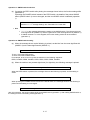
(c) When the following message is printed, press the FEED switch.
Select Function
Setting Mode: Feed SW / HEX Dump Mode: Power SW
Hint
When the POWER switch is pressed at this time, the printer becomes in HEX dump mode.
If you do not press any switch within 30 seconds after a message is printed, the printer
turns off.
When the POWER and ERROR lamps start to blink, release your finger from the POWER
and ERROR switches within 5 seconds. If it is ongoing, the printer exits function setting
mode. In such a case, turn the power off and try the procedure from (1) again.
(d) When the following message is printed, press the FEED switch.
[SETTING MODE] Yes: Feed SW / No: Power SW
Hint
If the POWER switch pressed, the printer exits the function setting mode and turns the
power off.
If you do not press any switch within 30 seconds after a message is printed, the printer
turns off.
The printer becomes in the function settings mode and becomes in the state of waiting for switch operation.
In the function setting mode, you can initialize or modify settings. To set the settings to defaults, perform
operation (1). To change settings, perform operation (2).
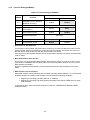
4-10
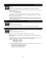
(1) Initializing SWDIP switch settings
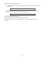
(a) When the following message is printed in the function setting mode, press the FEED switch.
Load Default Setting? Yes: Feed SW / No: Power SW
(b) When the following message is printed, the printer turns off.
The settings are set to defaults. Initialization is complete.
Default Setting Saved.
Setting Mode Finished.
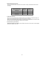
(2) Changing SWDIP switch settings
(a) When the following message is printed in the function setting mode, press the POWER switch.
Load Default Setting? Yes: Feed SW / No: Power SW
Hint
There are SWDIP switches from 1 to 4 in the printer, so set 8 bits within SWDIP switches
respectively.
In function setting mode, the POWER lamp blinks once by pressing either the POWER
switch or the FEED switch. Be sure to confirm the POWER lamp blinking in order to
ensure proper operation.
4-11
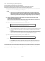
Operation 1: SWDIP switch selection
(a) If pressing the FEED switch after printing the message shown below, the function setting shifts
(operation 2).
If pressing the POWER switch instead of the FEED switch, the details of the printed SWDIP
switch (SWDIP switch 1) are not changed, and the next SWDIP switch is selected (operation
1).
DIP Switch setting mode.
DIP SW-1=******** Change Setting? Yes: Feed SW / No: Power SW
Hint
"********" in the message indicates the setting of the SWDIP switch. The leftmost bit is the
most significant bit (SWDIP*-8) and the rightmost bit is the least significant bit (SWDIP*-1).
If SWDIP switches 1 to 4 are skipped, the function setting mode can be terminated
(operation 3).
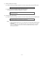
Operation 2: SWDIP switch setting
(a) When the message shown at the following is printed, set the bits from the most significant bit
(SWDIP*-8) to the least significant bit (SWDIP*-1).
Input 8 bits. 1: Feed SW / 0: Power SW
To set 1: Press the FEED switch.
To set 0: Press the POWER switch.
For example, to set 10101110, press the switches in the following sequence:
FEED, POWER, FEED, POWER, FEED, FEED, FEED, FEED, POWER.
(b) When the switches are pressed eight times (for eight bits), the following message is printed.
DIP SW-1=********” Save Setting? Yes: Feed SW / No: Power SW
When the FEED switch is pressed, the message shown at the following is printed, and the setting is
saved.
DIP SW-1=******** Saved.
When pressing the POWER switch instead of the FEED switch, the message shown at the following is
printed and the setting is not changed.
DIP SW-1 Not Changed.
After this operation, the function setting shifts next SWDIP switch (operation 1). After setting SWDIP switch 4,
the setting function exits setting mode (operation 3).
4-12
Operation 3: Exiting function setting mode
(a) If pressing the FEED switch after printing the message shown below, the function setting shifts
(operation 1).
DIP Switch setting mode. Continue: Feed SW / Quit: Power SW
If pressing the POWER switch after printing the message shown below, the printer exits the function
setting mode and turns off. The function setting is now complete.
Setting Mode Finished.
4.1.6 Function Settings by Commands
The command is transmitted to the printer by selected communication.
For details of commands, refer to Function Settings (DC2 ‘k’) command (“6.5.25 Auxiliary Function
Commands”).
4-13
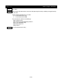
4.2 TEST PRINT
The printer has a test print function that prints the contents of Function Settings and character strings for test.
(a) Be sure that the thermal paper is set to the printer and the printer is turned off. If the thermal
paper is not set, set the thermal paper to the printer.
(b) Press the POWER switch and the FEED switch on the printer at the same time until the
POWER lamp lights, release the POWER switch first and then the FEED switch second.
(c) The test print is performed.
(d) The printer goes to print-ready status after test printing is completed.
4-14
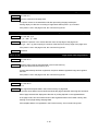
4.3 HEX DUMP MODE
This function can be used to check whether the host device transmits data to the printer correctly. Perform
the following steps.
(a) Be sure that the thermal paper is installed to the printer and the printer is turned off.
(b) Keep on pressing the POWER and FEED switches in six seconds.
(c) Release the POWER and FEED switches after blinking the POWER and ERROR lamps.
(d) Press the POWER switch after printing the message below.
Select Function
Setting Mode: Feed SW / HEX Dump Mode: Power SW
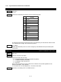
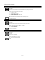
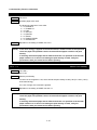
(e) After printing the message below, the printer enters a HEX dump mode.
[HEX DUMP MODE]
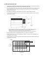
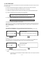
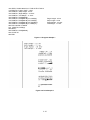
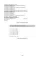
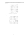
The example of printing using BASIC is shown below:
Input data from host computer. The data input through the printer interface is printed as hexadecimal
code, 16 bytes at a time. If the input buffer contains less than 16 bytes of data, it is printed when the
FEED switch is pressed.
16 bytes
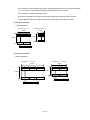
Input PRINT#1,"abcdefghijklmn" to the host computer and press the Return key.
The printer prints 'abcdefghijklmn' in hexadecimal number and two control codes (0DH and 0AH).
OK
[HEX DUMP MODE]
PRINT #1,"abcdefghijklmn"
61 62 63 64 65 66 67 68 69 6A 6B 6C 6D 6E 0D 0A
Printer
Host device
Less than 16 bytes
Input PRINT#1,"abc" to the host computer, press the Return key, and then press the FEED switch.
The printer prints 'abc' in hexadecimal number and two control codes (0DH and 0AH).
OK
[HEX DUMP MODE]
PRINT #1,"abc"
61 62 63 0D 0A
Printer
Host device
(f)
Press the POWER switch to exit the HEX dump printing.
Hint
Some BASIC use a PR# statement instead of PRINT#. Refer to the computer manual for
details on BASIC.
4-15
CHAPTER 5
LAMP DISPLAY AND SWITCH FUNCTION
This chapter explains printer status by lamp display and functions of switches.
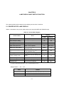
5.1 PRINTER STATE LAMP DISPLAY
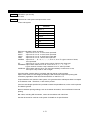
Table 5-1 lists states of the printer, display that by two lamps (POWER and ERROR lamps).
Table 5-1 Printer Status Signals
Printer status
Display
Error
POWER
ERROR
Power OFF
-
Off
Off
Power ON (Print-ready)
-
On
Off
Initializing
-
On
On
Out-of-paper error
Thermal paper is not inserted
On
Blink
Paper cover open error
Paper cover is opened
On
Blink twice
Battery low, power failure
Power supply voltage is out of the
stipulated range *1
Blink
On
Thermal head temperature
error
Thermal head temperature is out
of the stipulated range *2
Blink twice
On
Recharging
Battery pack is recharging
Blink
Off
Function setting mode
Mode where function settings can
be set
Off
On
-
Blink
Blink
Short blink
Short blink
Off
Blink
Function setting mode shifting
FLASH memory accessing
FLASH memory is operating
Hardware error
Error occurs in hardware
*1: Range of stipulated power supply voltage is 6.5V≦power supply voltage ≦9.7V
*2: Range of stipulated temperature is -10°C≦ head temperature ≦80°C
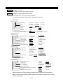
Display Pattern ○: On, ─: Off
Items
Blink
Pattern
─
○
─
─
○
○
─ ........
Short blink
○─○─○─○─○─○─○─○─○─○........
Blink twice
○─○
─
5-1
○─○
─
○─○
─ .......
5.2 ERROR RECOVERY PROCEDURE
When an error occurs, the printer stops printing operation. Moreover, when Busy Output When Error Occurs
is enabled in the Function Settings, the status of data reception becomes busy.
However, Some errors can be recovered to a status just before a printing stop after clearing errors.
Error recovery procedure is shown below.
In this case, the printer resumes the printing from next line or next dot line a print stopped.
Table 5-2 Error Recovery Procedure
Item
Out-of-paper
Recovery Procedure
Cut Paper mode:
Insert the thermal paper from the paper slot, the printer loads
the thermal paper automatically and returns to print-ready
status if the mark is detected. When the mark is not detected,
press the FEED switch to recover to print-ready status *1 .
Roll Paper / Mark Roll Paper mode:
Open the paper cover and replace the thermal paper. Close
the paper cover, so the printer returns to print-ready status
automatically one second later.
Paper cover open
Close the paper cover, so the printer returns to print-ready
status automatically one second later.
The printer returns to print-ready status automatically if
Thermal head temperature error thermal head temperature becomes within the stipulated
range. *2
Power failure
Return the power supply voltage to the stipulated range, and
then press the FEED switch. *1 *3
Hardware error
Non-recoverable error
*1: In this case, paper feed operation is performed.
*2: Range of stipulated temperature is -5°C≦ head temperature ≦75°C
*3: Range of stipulated power supply voltage is 6.5V≦power supply voltage ≦9.7V
5-2
5.3 POWER SWITCH
Turning ON / OFF the printer and changing the mode to the print-ready can be performed by the POWER
switch.
(NOTE) Always use the POWER switch to turn off the printer.
Do not power off the printer by removing the AC adapter or the battery pack. If
doing so, the memory may be damaged.
5.4 FEED SWITCH
The paper can be fed by the FEED switch.
The action differs depending upon SWDIP3-1 to 3-2 of the function settings.
Cut Paper / Roll Paper mode
The printer feeds a small amount of thermal paper by pressing this switch once and the switch is
held down, the thermal paper is fed continuously.
Mark Roll Paper mode
The printer feeds the paper until paper mark detection by pressing this switch once.
The printer stops its operation if the printer does not detect the mark after feeding the thermal
paper up to paper length which is set.
The amount of maximum paper length to mark detection can be set by Set default/Set test print
header (DC2 'i') command (6.5.25 Auxiliary Function Commands). The default value is 300 mm.
The printer does not feed the thermal paper if pressing FEED switch in the following case.
When the paper cover opens
When power supply voltage is larger than 9.7V.
When the printer is in the download mode. (For the download mode, refer to 6.5.26 Download
Mode)
5-3
CHAPTER 6
COMMAND DESCRIPTIONS
This chapter describes the functions of the commands supported by the printer.
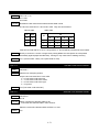
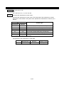
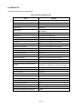
6.1 THE SUMMARY OF COMMAND FUNCTION
The printer supports the ESC/P based commands.
Table 6-1 Command Summary (1/4)
Command
Function
Page
ESC 'C'
Set Page Length at n Lines
6-19
ESC 'C' 0
Set Page Length at n Inches
6-19
ESC 'N'
Set Bottom Margin
6-19
ESC 'O'
Cancel Bottom Margin
6-20
ESC 'Q'
Set Right Margin
6-20
ESC 'l'
Set Left Margin
6-21
ESC '0'
Set 1/8-inch Line Spacing
6-23
ESC '2'
Set 1/6-inch Line Spacing
6-23
ESC '3'
Set n-dot-line Line Spacing
6-23
ESC 'B'
Set Vertical Tab Positions
6-25
ESC 'D'
Set Horizontal Tab Positions
6-26
CR
Print and Carriage Return
6-27
LF
Print and Line Feed
6-27
FF
Page Feed (Form Feed)
6-27
ESC 'J'
Print and Feed Paper
6-28
GS '<'
Marked Paper Form Feed
6-28
HT
Execute Horizontal Tab
6-29
VT
Execute Vertical Tab
6-29
ESC '$'
Set Absolute Position
6-29
ESC '\'
Set Relative Position
6-29
6-1
Table 6-1 Command Summary (2/4)
Command
Function
Page
ESC 'R'
Select International Character
6-31
ESC 't'
Select Character Code Table
6-31
DC2 'y'
Euro Character Specify
6-32
ESC '%'
Set/Cancel Download Character Set
6-34
ESC '&'
Define Download Characters
6-34
DC2 'D'
Download Characters Area Operation
6-35
SO
Select Expanded Character Mode with Automatic Cancellation
6-36
DC4
Cancel Expanded Character Mode with Automatic Cancellation
6-36
ESC 'W'
Select/Cancel Expanded Character Mode
6-36
ESC 'w'
Select/Cancel Double Height Mode
6-36
ESC 'E'
Select Emphasized Print Mode
6-36
ESC 'F'
Cancel Emphasized Print Mode
6-37
ESC 'G'
Select Double Print Mode
6-37
ESC 'H'
Cancel Double Print Mode
6-37
ESC '-'
Select/Cancel Underline Mode
6-37
ESC '!'
Set Print Mode
6-38
DC2 'Y'
Character Rotation
6-39
ESC SP
Set Character Spacing
6-40
FS '&'
Select Kanji Mode
6-43
FS '.'
Cancel Kanji Mode
6-43
FS 'C'
Select Kanji Code System
6-43
FS 'r'
Select Kanji Quarter Size Character Mode
6-44
FS DC2
Cancel Kanji Quarter Size Character Mode
6-44
FS '2'
Define User-defined Character
6-45
DC2 'G'
User-defined Character Area Operation
6-46
FS 'J'
Select Vertical Writing
6-47
FS 'K'
Select Horizontal Writing
6-47
FS 'W'
Select/Cancel Quadruple-size Kanji Character
6-47
FS '-'
Select/Cancel Kanji Underline Mode
6-48
FS '!'
Set Kanji Print Mode
6-49
FS 'S'
Set Kanji Left- and Right-side Spacing
6-50
ESC '*'
Set Bit Image Mode
6-53
GS 'v' '0'
Raster Bit Image Print
6-55
DC2 'T'
Stamp Define
6-58
DC2 'S'
Stamp Select
6-59
DC2 'V'
Stamp Print Out
6-59
DC2 'W'
Stamp Abort
6-59
DC2 'U'
Stamp Clear
6-59
CAN
Cancel Print Data in Buffer
6-61
6-2
Table 6-1 Command Summary (3/4)
Command
Function
Page
DC3 '+
Ruler Line ON
6-62
DC3 '-'
Ruler Line OFF
6-62
DC3 'A'
Ruler Line Buffer A
6-62
DC3 'B'
Ruler Line Buffer B
6-62
DC3 'C'
Ruler Line Buffer Clear
6-63
DC3 'D'
Define Ruler Line by Dot
6-63
DC3 'F'
Define Ruler Line with Repeating Patterns
6-63
DC3 'L'
Define Ruler Line by Line
6-63
DC3 'V'
Ruler Line LSB/MSB Image
6-64
DC3 'P'
Print One dot Line after Printing Line Buffer Data
6-64
DC3 '('
Continuous Ruler Line Command Input
6-64
DC2 'P'
Define Optional Font
6-66
DC2 'O'
Select Optional Font
6-67
DC2 'Q'
Erase Optional Font
6-67
GS 'H'
Select HRI Character Print Position
6-69
GS 'f'
Select HRI Character Font
6-69
GS 'h'
Set Bar Code Height
6-69
GS 'k'
Print Bar Code
6-70
GS 'w'
Set Width of Bar Code
6-72
GS 'P'
Set Bar Code Print Position
6-72
GS 'n'
Nominal Fine Element Width
6-72
GS 'o'
PDF Row Height
6-73
GS 'p' 0
PDF417 Print
6-73
DC2 ';'
QR Code and Data Matrix Module Sizes
6-74
GS 'p' 1
QR Code Print
6-74
GS 'p' 2
Data Matrix Print
6-75
GS 'p' 3
Maxi Code Print
6-76
DC2 'E' 0
Set Routine Format
6-83
DC2 'E' 1
Set Routine Parameter Data
6-85
DC2 'E' 2
Execute Routine Format
6-86
DC2 'E' 3
Delete All Routine Data
6-86
DC2 'z' 0
Page Mode Select
6-88
DC2 'z' 1
Page Mode Print
6-89
DC2 'z' 2
Page Mode Vertical Position Specify
6-89
DC2 'z' 4
Page Mode Data Registration
6-89
DC2 'z' 5
Page Mode Data Calling
6-89
6-3
Table 6-1 Command Summary (4/4)
Command
Function
Page
DC2 '$' '1'
Rectangle Print
6-90
DC2 '$' '2'
Line Type Property
6-91
DC2 '$' '3'
Line Width Property
6-91
DC2 '$' '4'
Fill Property
6-91
DC2 'e'
Enable/Disable Automatic Status Transmission
6-93
DC2 'r'
Send Remaining Memory Capacity
6-93
DC2 'v'
Send VP Voltage
6-94
DC2 'q'
Send External RAM Checksum
6-94
DC2 'l'
Send SWDIP Switch Settings
6-94
DC2 'j'
Execute Response Request
6-95
DC2 'F'
Select Character Font Size
6-97
DC2 '!'
Select Paper
6-99
DC2 '~'
Select Print Density
6-99
GS 'E'
Motor Speed Select
6-100
DC2 'a'
Set Automatic Power-off Time
6-100
DC2 '#'
Select Overlap Mode
6-100
DC2 '='
Select Image LSB/MSB
6-101
GS 'g' '0'
Maintenance Counter Initialization
6-102
GS 'g' '1'
Maintenance Counter Preservation
6-102
GS 'g' '2'
Maintenance Counter Transmission
6-103
DC2 '{'
User Area Data Registration/Clears
6-104
DC2 '*' '1'
User Area Defragment
6-104
DC2 '*' '2'
Remaining User Area Response
6-104
DC2 'R'
User Area Initialization
6-105
ESC '@'
Initialize Printer
6-105
DC2 's' 't' 'p'
Power Off
6-105
DC2 'k'
Function Settings
6-107
DC2 'i'
Set Default/Set Test Print Header
6-108
DC2 DC2
Download Mode Selection
6-111
'@'
Hardware Reset
6-111
','
Area of 2-byte Character Download
6-111
'{'
Data Structure of a 2-byte Character
6-115
6-4
6.2 FUNCTION CODES
One of the following control codes is attached to the beginning of each command. These control codes are
also called function codes.
HT(09H), LF(0AH), VT(0BH), FF(0CH), CR(0DH), SO(0EH), DC2(12H), DC3(13H), DC4(14H),
CAN(18H), ESC(1BH), FS(1CH), GS(1DH)
Function codes may or may not have parameters or image data.
The number of bytes per command differs based on the type of command. Some commands are only 1 byte
long, while some are up to several hundred bytes in length.
6.3 CHARACTER CODES
This section describes character codes.
The character code range and User-defined character codes are different depending on JIS code system or
Shift JIS code system which is selected with the Kanji Code System Select command (FS 'C').
6.3.1 JIS Code System
When the JIS Code System is selected with the Kanji Code System Select command (FS ‘C’), Kanji characters
can be printed using 2-byte character codes after Kanji mode is selected with the Kanji Mode Specify
command (FS '&').
The command functions as 1-byte character code or the first or second byte of 2-byte character code.
If a command is input in 2-byte character codes, the next data is always processed as the first byte. However,
the next data is 1-byte character code for Cancel Kanji Mode, FS '.'.
If a command is input as the second byte of 2-byte character code, the first byte is ignored.
(1) 1-byte character codes
00H - 1FH:
Commands are processed as commands.
20H - 7EH:
The codes are processed as 1-byte character code.
7FH:
Ignored (except that when 7FH is defined as downloaded character and download
character operation is effective).
80H - FEH:
The codes are processed as 1-byte character code.
FFH:
It differs from each character set.
If the extended graphics character set or the katakana character set are selected,
they are ignored.
If the Codepage 1252 is selected, it is processed as the character code.
(2) 2-byte character codes
2-byte character codes specify Kanji characters, Kanji quarter size characters or User-defined
characters.
- First byte
00H:
1-byte character area in Kanji ROM. Specify the 1-byte character in the Kanji ROM
with the next data of 00H.
21H - 76H:
2-byte character area.
77H:
User-defined character area.
78H - 7EH:
2-byte character area.
If the codes other than the above are not commands, these codes are ignored.
The next data to be received is processed as the first byte.
6-5
- Second byte
(If the first byte is 00H)
20H - 7EH:
The codes are processed as 1-byte character in the Kanji ROM.
80H - FEH:
The codes are processed as 1-byte character in the Kanji ROM.
FFH:
It differs from each character set.
If the extended graphics character set or the katakana character set are selected,
they are ignored with the first byte.
If the Codepage 1252 is selected, it is processed as the character code.
(If the first byte is not 00H)
21H - 7EH:
The codes are processed as the second byte of Kanji characters or user-defined
characters.
If the codes other than the above are not commands, these codes are ignored with the first byte. The next
data to be received is processed as the first byte.
The codes not defined as JIS or special characters in the 2-byte character area are processed as 2-byte
character spaces.
Printed 2-byte character code conforms to JIS X 0208-1997.
(3) 2-byte character codes when mounting Korean character
2-byte character codes specify Korean or User-defined characters.
- First byte
00H:
1-byte character area. Specify the 1-byte character with the next data of 00H.
77H:
User-defined character area.
A1H - FDH:
Korean character area.
The other codes are ignored unless they are commands.
The next data to be received is processed as the first byte.
- Second byte
(If the first byte is 00H)
20H - 7EH:
The codes are processed as 1-byte character.
80H - FEH:
The codes are processed as 1-byte character.
FFH:
It differs from each character set.
If the extended graphics character set or the katakana character set are selected,
they are ignored with the first byte.
If the Codepage 1252 is selected, it is processed as the character code.
(If the first byte is 77H)
21H - 7EH:
The codes are processed as the second byte of user-defined characters.
6-6
(If the first byte is A1H to FDH)
A1H - FEH:
The codes are processed as the second byte of Korean.
The other codes are ignored unless they are commands.
The next data to be received is processed as the first byte.
6.3.2 Shift JIS Code System
If the Shift JIS Code System is selected with the Kanji Code System Select command, Kanji characters can be
printed with 2-byte character codes without entering the Kanji Mode Specify command.
The command functions as 1-byte character code or the second byte of 2-byte character code.
If a command is input for the second byte of 2-byte character code, the first byte is ignored.
(1) 1-byte character codes
00H - 1FH:
Commands are processed as commands.
20H - 7EH:
The codes are processed as 1-byte character code.
7FH:
Ignored (except that when 7FH is defined as downloaded character and download
character operation is effective).
80H - FEH:
See (2).
FFH:
It differs from each character set.
If the extended graphics character set or the katakana character set are selected,
they are ignored with the first byte.
If the Codepage 1252 is selected, it is processed as the character code.
(2) 2-byte character codes
2-byte character codes specify Kanji and User-defined characters.
- First byte
81H - 9FH:
2-byte character area.
E0H - EBH:
2-byte character area.
ECH:
User-defined character area.
EDH - EFH:
2-byte character area.
The other codes 80H - FEH are processed as 1 byte characters.
- Second byte
40H - 7EH:
The codes are processed as the second byte of Shift JIS code or user defined
character.
80H - FCH:
The codes are processed as the second byte of Shift JIS code or user defined
character.
If the codes other than the above are not commands, these codes are ignored with the first byte.
The codes not defined as Shift JIS or special characters in the 2-byte character area are processed as
2-byte character spaces.
6-7
(3) 2-byte character codes when mounting Korean character
2-byte character codes specify Korean or User-defined characters.
- First byte
A0H:
User-defined character area.
A1H - FDH:
Korean characters area when selecting Korean.
The other codes are ignored unless they are commands.
The next data to be received is processed as the first byte.
- Second byte
(If the first byte is A0H)
A1H - FEH:
The codes are processed as the second byte of user-defined characters.
(If the first byte is A1H-FDH)
A1H - FEH:
The codes are processed as the second byte of Korean.
The other codes are ignored unless they are commands.
The next data to be received is processed as the first byte.
6-8
6.4 MEMORY
Check remaining memory size when using optional fonts, routine command or stamp. Refer to this section to
use those functions.
6.4.1 Extended RAM Memory
(1) Memory area
The printer has 232280 bytes of memory for User-defined characters, downloaded characters, optional
fonts, routine command and stamp.
Set or clear memory area for each function.
Setting of the memory area means to create a partition for certain function exclusively.
Clearing the memory area means to remove a partition for a certain function.
Usually users do not need to check it, however, make sure that the required memory does not exceed the
remaining memory size when using optional fonts, routine command, and stamp.
The following memory sizes shown in Table 6-2 are set right after initialization.
Table 6-2 Memory Sizes Right After Initialization
Memory size
(bytes)
Availability of clear
User-defined characters
9784
Available
Download characters
6248
Available
Optional fonts
0
Available
Routine command (DC2 'E')
0
Available
Stamp
0
Available
Uses
Memory area of User-defined characters and downloaded characters are set in initialization.
Memory area can be cleared by a command and can be increased for optional fonts, routine command or
stamp.
When registering optional fonts, routine command or stamp, always check the remaining memory size.
Registering data that exceeds the remaining memory size is ignored.
When setting optional fonts, fixed size format or fixed size parameters, memory area is set automatically
by command input.
When setting memory area, memory control information is always added to the head of the memory area.
Number of bytes for memory control information differs according to each function. The number of bytes
for used for memory control information is shown in Table 6-3.
Table 6-3 Number of Bytes for Memory Control Information
Uses
Number of bytes
User-defined characters
8
Downloaded characters
8
Optional fonts
12
Routine command (DC2 'E')
10
Stamp
11
6-9
(2) Capacity of memory size
Allocated memory size depend on used function. User-defined character and downloaded character is
allocated size of 9784 and 6248 bytes respectively. Optional fonts, routine function or stamp is allocated
size of (number of data + Memory control Information). Moreover, registration of routine function and
stamp requires the above-mentioned size per registration data.
(3) Precautions for stamp function
Do not use the commands such as which to be allocated or freed as listed below during stamp operation.
Table 6-4 Commands for Allocating or Freeing Memory Area
Command
Command name
DC2 'T'
Stamp Define
DC2 'U'
Stamp Clear
DC2 'P'
Define optional font
DC2 'Q'
Erase optional font
DC2 'E' 0
Set routine format
DC2 'E' 1
Set routine parameter data
DC2 'E' 3
Delete all routine data
DC2 'z' 0
Page Mode Select
DC2 'D'
Download characters area operation
DC2 'G'
User-defined character area operation
DC2 'R'
User Area Initialization
If the commands listed in Table 6-4 are input during selection of the stamp, the stamp selection is
canceled.
(4) Initialization of memory
The printer does not erase the content of the memory using the AC adapter or the battery pack with active
voltage even if Reset command or Power off command is input or the printer is turned the power off.
However, the printer initializes the memory during its next start-up when disconnecting the power supply
or executing the User Area Initialization command.
(5) Memory usage at two-dimensional bar code function
At two-dimensional bar code print, empty area of the external RAM is used temporarily at bar code print.
The two-dimensional bar code printing performs depending on their parameter, available memory
capacity and settable data size as described below:
When the parameter of the command is outside the range:
CPU ignores the part outside and processes the remaining data as character codes.
When the available memory capacity is short:
All of data is processed as normal code.
When the command is normal and memory area has been allocated but the data more than
maximum data size is specified:
All of the data is discarded. Since settable data size varies depending on the type of
two-dimensional bar codes, refer to each explanation of two-dimensional bar code commands.
Moreover, note that settable data size changes in accordance with the value of specified parameter.
6-10
When the command is normal and memory area has been allocated, but the bar code cannot be
printed within printable area:
The command is ignored.
When the command is normal, memory area has been allocated and the bar code can be printed
within printable area:
The two-dimensional bar code is printed.
The necessary empty capacity differs according to types and sizes of bar codes.
(a) Used Memory Capacity of PDF417
The total empty area of area 1 to 4 shown in Table 6-5 is necessary for PDF417 print.
For an example, when number of bar code data byte =15, error correction level=3, number of column
number=8, and number of row=20;
Area1 = 15+1 = 16 bytes
Area2 = 2048 bytes
Area3 = 2 (3+ 2) = 32 bytes
Area4 = (8+7) 202 = 600 bytes
Total = 2696 bytes
(Empty area size: Even number of bytes)
Table 6-5 GS 'p' 0 Used Memory Capacity of PDF417 Print Command
Area
Memory Usage
Area1
N+1 bytes *1
Area2
2048 bytes
Area3
(L+ 2)
Area4
*1:
*2:
*3:
2
bytes *2
(C+7)R2 bytes *3
N: Number of bar code data byte
When empty capacity of the external RAM is an odd number, one more byte is necessary.
When N+1 is an odd number, one more byte is necessary.
L: Error correction level
C: Number of column, R: Number of row
6-11
(b) Used Memory Capacity of QR Code
The total empty area of area1 to 3 shown in Table 6-6 is necessary for QR Code print.
For an example, when number of bar code data byte=30, model=2, and version=4;
Area1 = 302+560 = 620 bytes
Area2 = 8006 bytes
Area3 = 33int
[
33 + 7
8
] 3+1 = 496 bytes
Total = 9122 bytes
(Empty area size is even number of bytes)
Table 6-6 GS 'p' 1 Used Memory Capacity of QR Code Print Command
Area
Area1
Memory usage
N2+560 bytes
Area 2
Area 3
*1
8006 bytes
M×int [
M+ 7
8
] ×3 bytes
*2
M=17+V×4
*1:
*2:
N: Number of bar code data
When empty capacity of the external RAM is an odd number, one more byte is necessary.
When number of bar code data byte is an odd number, one more byte is necessary.
M: Number of modules for one side of the QR Code.
V: Version
The int () means that less than a decimal point will be omitted.
When area 3 becomes an odd number, one more byte is necessary.
6-12
(c) Used Memory Capacity of Data Matrix
The total empty area of area1 to 4 shown in Table 6-7 is necessary for Data Matrix print.
For an example, when number of bar code data byte =20 and symbol size=22 (vertical) 22
(horizontal);
Area1 = 20 bytes
Area2 = 2230 bytes
Area3 = (30+20+1) 2 = 102 bytes
Area4-A = 1 (30+68) 2 = 196 bytes
Area4-B= 33 {int[
20 + 15
] × 20 + int[ 22 + 15
16
16
] }22 × 2
= 168 bytes
Total = 2548 bytes (Area4 uses a value of Area4-A.)
(Empty area size is an even byte number.)
Table 6-7 GS 'p' 2 Used Memory Capacity of Data Matrix Print
Area
Memory usage
Area1
N bytes *1
Area2
2230 bytes
Area3
(D+E+1)2 bytes *2
I(B+68) 2 bytes *3
Area4-A
{int[
Area4-B
Xm + 15
] × Ym + int[ X + 15
16
16
*4
] }Y × 2
bytes *3
*5
*1: N: Number of bar code data
When empty capacity of the external RAM is an odd number, one more byte is necessary
When number of bar code data byte is an odd number, one more byte is necessary
*2: D: Number of data code word.
E: Number of error correction code word.
These value are decided from symbol sizes. See Table 6-8
*3: Area 4-A and area 4-B are used commonly. The larger number will be used
*4: The I will be calculated as follows:
・When E is 68 or less, I=1
・When E exceeds 68,
I=int
(
E + 67
68
)
When the above value is an odd number, plus 1 to the value.
B will be calculated as follows:
B=int
(
D + I-1
I
)
*5: X: Horizontal size of the symbol
Y: Vertical size of the symbol
Xm: Horizontal size of the map matrix
Ym: Vertical size of the map matrix
See Table 6-8 for sizes of the map matrixes.
The int () means that less than a decimal point will be omitted.
6-13
Table 6-8 Data Matrix Symbol Sizes
Symbol size
Map matrix size
Number of the Code Word
Vertical
Horizontal
Vertical
Horizontal
Data
Error correction
10
10
8
8
3
5
12
12
10
10
5
7
14
14
12
12
8
10
16
16
14
14
12
12
18
18
16
16
18
14
20
20
18
18
22
18
22
22
20
20
30
20
24
24
22
22
36
24
26
26
24
24
44
28
32
32
28
28
62
36
36
36
32
32
86
42
40
40
36
36
114
48
44
44
40
40
144
56
48
48
44
44
174
68
52
52
48
48
204
84
64
64
56
56
280
112
72
72
64
64
368
144
80
80
72
72
456
192
88
88
80
80
576
224
96
96
88
88
696
272
104
104
96
96
816
336
120
120
108
108
1050
408
132
132
120
120
1304
496
144
144
132
132
1558
620
8
18
6
16
5
7
8
32
6
28
10
11
12
26
10
24
16
14
12
36
10
32
22
18
16
36
14
32
32
24
16
48
14
44
49
28
6-14
(d) Used Memory Capacity of MaxiCode
The total empty area of area1 to 2 shown in Table 6-9 is necessary for MaxiCode print.
For an example, when number of bar code data byte=33;
Area 1 = 33+1 = 34 bytes
Area 2 = 7684 bytes
Total = 7718 bytes
(Empty area size is an even byte number.)
Table 6-9 GS 'p' 3 Used Memory Capacity of MaxiCode Print
Area
Memory Usage
Area 1
N bytes *1
Area 2
7684 bytes
*1:N: Number of bar code data
When empty capacity of the extended RAM is an odd number, one more byte is necessary.
When number of bar code data byte is an odd number, one more byte is necessary.
6-15
6.4.2 FLASH Memory
The printer stores data such as User-defined character, downloaded character, optional font, routine function,
stamp and template data into FLASH memory. Of these data, User-defined character, downloaded character,
optional font and template data can be used dedicated memory area. Moreover, FLASH memory has shared
memory area as 256K byte user area for routine function and stamp.
Data except template data stored into FLASH memory is used when that is not present into extended RAM.
If data is present in both of FLASH memory and extended RAM, the printer treats data in extended RAM as
priority.
When allocating memory area for User-defined character or downloaded character in extended RAM, the
printer copies data of User-defined character or downloaded character if those data are present in FLASH
memory.
(1) User area in FLASH memory management
Memory in the user area has the following conditions:
In use state (storage state)
Release state (Erasable state)
Empty state
In use
Release
Empty
All Extension memories are in “Empty state” at shipping.
When some data is saved in the memory, the memory turns to “In use state”.
When the data is in use condition is released, the memory turns to “Released state (Erasable state).” This
area cannot be used again in this state.
[1] Shipping state
[2] State that some data are
registered.
[3] State that the registered
data is released.
Data (1) In use state
Data (1) Released state
Empty state
Empty state
Empty state
[4] State that the registration and a
release are repeated.
Data (1) Released state
[5] State that the Extension Memory Area
Control command (DC2*1) is executed.
Data (2) In use state
Data (3) In use state
Data (2) In use state
Data (3) In use state
Data (5) In use state
Data (4) Released state
Data (5) In use state
Empty state
Data (6) Released state
Empty state
6-16
When data storage and release are repeated, the memory state turns to the [4] state.
To use the “Released state (Erasable state)” area again, execute the User Area Defragment (DC2 '*' '1')
command.
The [5] shows the memory state after the command is executed.
Executing Remaining User Area Response (DC2'*' '2') command to check the current remaining area.
Remaining Memory Response command in user area responds the current available amount of FLASH
memory.
(2) Precautions on data in FLASH memory when rewriting, freeing and allocating
The maximum rewritable number of the FLASH memory is approximately 100000 times. Execute the
User Area Defragment command after getting low memory for restraining the numbers of the memory
rewriting.
Do not turn the power off during FLASH memory writing/erasing. If doing so may cause FLASH memory
damage and it may not work. To confirm the FLASH memory writing/erasing, send Execute Response
Request (DC2 ‘j’) command (6.5.23 Status Commands) behind the command as the above-mentioned
and check response code.
6-17
6.5 COMMAND DESCRIPTION
Each command for the printer is described respectively.
This section explains each command.
6.5.1 Command Format
Each command is described in the following format.
(a)
(b)
(c)
(a)
(b)
(c)
6-18
6.5.2 Formatting Commands
ESC 'C' n
Code
Set page Length at n Lines
1BH 43H n
1n127
Function Set page length at n lines.
The page length is (current line spacing x n) dot lines.
If the line spacing is zero, this command is ignored.
The current position becomes the beginning of the page.
The bottom margin set by ESC 'N' is canceled.
If n = 0, the page length is set at n inches.
This setting is canceled by Page Mode Select (DC2 'z' 0) command.
Moreover, this command is ignored in the page mode.
Default
Cut paper mode
: 38 lines (line spacing 34 dots lines)
Roll paper mode
: No page length setting
Mark roll paper mode : 38 lines (line spacing 34 dots lines)
ESC 'C' 0 n
Code
Set Page Length at n Inches
1BH 43H 00H n
1n22
Function Sets the page length at n inches.
The current position becomes the beginning of the page.
The page length is n x 203 dot lines.
The bottom margin set by ESC 'N' is canceled.
If n = 0 or n23, this command is ignored.
This setting is canceled by Page Mode Select (DC2 'z' 0) command.
Moreover, this command is ignored in the page mode.
Default
Cut paper mode
: 6.4 inches (1292 dots lines)
Roll paper mode
: No page length setting
Mark roll paper mode : 6.4 inches (1292 dots lines)
ESC 'N' n
Code
Set Bottom Margin
1BH 4EH n
1n127
Function Sets the bottom margin at n lines.
The last dot (n x current line spacing) of the page is the skip amount (non-printable area).
The skip amount does not change even if the line spacing is set after setting the bottom margin.
The bottom margin is canceled when the page length is modified.
If the bottom margin exceeds the page length, this command is ignored.
If the page length is not specified in the initial state in the roll paper mode, this command is
ignored.
This setting is canceled by Page Mode Select (DC2 'z' 0) command.
Moreover, this command is ignored in the page mode.
Default
The bottom margin is not defined.
6-19
ESC 'O'
Code
Cancel Bottom Margin
1BH 4FH
Function Cancels bottom margin.
If the page length is not specified in the initial state in the roll paper mode, this command is
ignored.
Default
The bottom margin is canceled.
Top of the page
Printable area
The defined page
length
The defined bottom
margin
Non-printable area
ESC 'Q' n
Code
Set Right Margin
1BH 51H n
1n255
Function Sets the right margin at n columns from the left edge (first column).
Column n (current character pitch x n) from the left edge becomes the right margin.
The character width includes character spacing. The character width is also doubled in
double-width setting. The character width is not calculated by double when Select expanded
character mode with automatic cancellation (SO) command is selecting.
The line buffer data is cleared and the next print position becomes the left margin.
The right margin does not move if the character pitch is changed later.
When n is smaller than the left margin columns, the command is ignored.
If the printable area is one character or less, one character is printed.
This command is ignored in the page mode.
Default
Maximum number of digits for printing. (at shipping)
Printer initial state after power-on can be changed by Set default/Set test print header (DC2 'i')
command.
6-20
ESC 'I' n
Set Left Margin
Code
1BH 6CH n
0n255
Function Sets the left margin at n columns from the left edge (first column).
Column n (current character pitch x n) from the left edge becomes the left margin.
The character width includes character spacing. The character width is also doubled in
double-width setting. The character width is not calculated by double when Select expanded
character mode with automatic cancellation (SO) command is selecting.
The line buffer data is cleared and the next print position becomes the left margin.
The left margin does not move if the character pitch is changed later.
When n is larger than the right margin columns, the command is ignored.
If the printable area is one character or less, one character is printed.
This command is ignored in the page mode.
Default
n=0 (at shipping)
Printer initial state after power-on can be changed by Set default/Set test print header (DC2 'i')
command.
When the left margin is set at fifth column and the right margin is set at 17th column, the
printable area is as follows:
Columns
1
2
Right margin
▼
Left margin
▼
3
4
5
Non-printable area
6
7
8
9
10
11
12
13
14
Printable area
Maximum printable area
6-21
15
16
17
18
19
20
21
22
Non-printable area
100 OPEN "COM1:9600,N,8,1" FOR OUTPUT AS #1
110 PRINT #1,"Page Length : 5 line"
120 PRINT #1,"Skip Length : 2 line"
130 PRINT #1,"Right Margin : 34 char"
140 PRINT #1,"Left Margin : 17 char"
150 PRINT #1,CHR$(&H0D);
160 PRINT #1,CHR$(&H1B);"C";CHR$(5);
170 PRINT #1,CHR$(&H1B);"N";CHR$(2);
180 PRINT #1,CHR$(&H1B);"Q";CHR$(34);
190 PRINT #1,CHR$(&H1B);"l";CHR$(17);
200 FOR I=&H20 TO &HFE
210 PRINT #1,CHR$(I);
220 NEXT I
230 PRINT #1,CHR$(&H0D);
240 CLOSE #1
250 END
'Page Length : 5 line
'Skip Length : 2 line
'Right Margin : 34 char
'Left Margin : 17 char
Figure 6-1 Program Sample 1
Figure 6-2 Print Sample 1
6-22
6.5.3 Line Spacing Commands
ESC '0'
Code
Set 1/8-inch Line Spacing
1BH 30H
Function Sets the line spacing amount to 1/8 of an inch (26 dots lines).
If the line buffer contains data and the line spacing amount is smaller than the character height,
the data in the buffer is printed and line feeding is performed by the character height.
Default
34 dots lines
Printer initial state after power-on can be changed by Set default/Set test print header (DC2
'i')command.
ESC '2'
Code
Set 1/6-inch Line Spacing
1BH 32H
Function Sets the line spacing to 1/6 of an inch (34 dots lines).
If the line buffer contains data and the line spacing amount is smaller than the character height,
the data in the buffer is printed and line feeding is performed by the character height.
Default
34 dots lines
Printer initial state after power-on can be changed by Set default/Set test print header (DC2 'i')
command.
ESC '3' n
Code
Set n-dot-line Line Spacing
1BH 33H n
0n255
Function Sets line spacing.
The line spacing is set to n dot lines.
If the line buffer contains data and the line spacing amount is smaller than the character height,
the data in the buffer is printed and line feeding is performed by the character height.
Default
34 dots lines
Printer initial state after power-on can be changed by Set default/Set test print header (DC2 'i')
command.
6-23
100 OPEN "COM1:9600,N,8,1" FOR OUTPUT AS #1
110 PRINT #1,CHR$(&H1B);"0";
120 PRINT #1,"ESC+0 ----- 1/8 inch line space"
130 PRINT #1,CHR$(&H1B);"2";
140 PRINT #1,"ESC+2 ----- 1/6 inch line space"
150 FOR I=0 TO 96 STEP 24
160 PRINT #1,CHR$(&H1B);"3";CHR$(I);
170 PRINT #1,"ESC+3+n -----";I;"dot-line line space"
180 NEXT I
190 PRINT #1,"---------------------------------------"
200 CLOSE #1
210 END
Figure 6-3 Program Sample 2
Figure 6-4 Print Sample 2
6-24
6.5.4 Tab Setting Commands
ESC 'B' {DATA} NUL
Code
Set Vertical Tab Positions
1BH 42H {p1 p2••• pk} 00H
1p255
0k16
Function Sets the vertical tab position.
The tab position is the (current line spacing × p lines) dot position with respect to the page
starting position.
If the line spacing is zero, ESC 'B' is ignored and the subsequent data is processed as normal
data.
The positions, p, are input in ascending order and the command ends with 00H (NUL). The
value of p is equal to or less than the value of the preceding p, the vertical tab position setting
ends, and the following data is processed as normal data.
Preset vertical tabs are cleared.
A maximum of 16 vertical tab positions k can be set. If more tab positions are specified, they are
ignored until the value becomes 00H or the preceding value.
ESC 'B' NUL clears all vertical tab positions.
If p exceeds the page length, the tab position is invalid. The following data is processed as
normal data.
Even if the line spacing is changed after setting vertical tab positions, the tab positions are not
changed.
If the page length is not specified in the initial state in the roll paper mode, this command is
ignored.
Default
No definition.
When the vertical tab is set at every fifth line and the vertical tab execution (VT command) and
'VTAB' are sent alternately, the print operation is as follows.
Line spacing
Tab position
Tab position
4
4
1
2
3
4
5
6
7
8
9
10
11
12
VT command
VTAB
VT command
VTAB
6-25
ESC 'D' {DATA} NUL
Code
Set Horizontal Tab Positions
1BH 44H {p1 p2•••pk} 00H
1p255
1k32
Function Sets horizontal tab positions.
The tab position is the (current character with × p columns) position with respect to the left
margin.
The character width includes the character spacing. The character width is also doubled in
double-width mode. The character width is not calculated by double when Select expanded
character mode with automatic cancellation (SO) command is selecting.
The positions, p, are input in ascending order and the command ends with 00H (NUL). The
value of p is equal to, or less than the value of the preceding p, the horizontal tab position setting
ends. The following data is processed as normal data.
Tab positions exceeding the right margin are invalid. They become valid when the right margin
is changed so that they are included in the printable area.
Preset horizontal tabs are cleared.
Up to 32 tab positions k can be set. Data which exceeds 32 tab positions will be ignored until the
value becomes 00H or the preceding value.
ESC 'D' NULL clears all horizontal tab positions.
Default
Every eight Katakana characters in 24-dot fonts.
When the horizontal tab is set at every seventh column, the horizontal tab execution (HT
command) and 'HTAB' are sent alternately, the printing operation is as follows.
Columns
1
2
Tab position
▼
Tab position
▼
3
HT command
4
5
6
7
8
9
10
11
H
T
A
B
12
13
14
HT command
6-26
Tab position
▼
15
16
17
18
H
T
A
B
19
20
21
HT command
22
6.5.5 Print and Paper Feed Commands
CR
Code
Print and Carriage Return
0DH
Function Functions the same as an LF command.
If the line buffer contains data and the line spacing amount is smaller than the character height,
the data in the buffer is printed and line feeding is performed by the character height.
LF
Code
Print and Line Feed
0AH
Function After data in the line buffer is printed out, the printer feeds one line.
The next print starting position becomes the beginning of the next line (left margin).
If the line buffer contains data and the line spacing is smaller than the character height, the data
in the line buffer is printed and one line is fed by the character height.
If the line buffer does not contain data before this code is received, the printer only feeds one line.
The select expanded character mode with automatic cancellation selected by SO is canceled.
The LF command that follows CR is ignored.
FF
Code
Page Feed (Form Feed)
0CH
Function When page length is specified, the printer performs page feed up to specified page length after
data in the line buffer is printed out.
When page length is not specified, the printer performs page feed up to mark by specified value
with Set default/Set test print header (DC2 'i')command after data in the line buffer is printed out.
The next print starting position becomes the beginning of the next line (left margin).
The select expanded character mode with automatic cancellation selected by SO is canceled.
In the cut paper mode:
If an out-of-paper error occurs during page feeding, the page feed ends at the time. Then, the
paper is fed at low speed. When new paper is loaded, it is not fed, and the page insertion
position is regarded as the beginning of the page.
In the roll paper mode:
When page length is not specified, this command is ignored. When page length is specified, if an
out-of-paper error occurs during page feeding, the page feed ends at the time. When new paper
is loaded, it is not fed, and the page insertion position is regarded as the beginning of the page.
In the mark roll paper mode:
The paper mark is detected by this command and paper form feed is executed. If an
out-of-paper error occurs, the printer operation is same as in the roll paper mode.
6-27
ESC 'J' n
Code
Print and Feed Paper
1BH 4AH n
0n255
Function Prints the data in the print buffer and feeds the paper one dot line.
If the line buffer contains data and n is smaller than the character height, the data in the line
buffer is printed and one line is fed by the character height.
If the line buffer contains data, the select expanded character mode with automatic cancellation
selected by SO is canceled.
If the line buffer does not contain data before this code is received, the printer only feeds n dot
lines.
The predetermined line spacing remains unchanged.
ABC
n
n
GS '<'
Code
Marked Paper Form Feed
1DH 3CH
Function Performs the marked paper form feed.
This command is effective only when marked paper is selected.
In the Mark Roll Paper mode or Cut Paper mode, the printer performs its operation as same as
Page feed (FF) command.
In the Mark Roll Paper mode, the printer executes the paper form feed to the cutting position. If
data is remaining in the line buffer, the printer executes paper feed after printing data in the line
buffer.
The select expanded character mode with automatic cancellation selected by SO is canceled.
6-28
6.5.6 Print Position Commands
HT
Code
Execute Horizontal Tab
09H
Function Moves the print position to the next horizontal tab position.
This command is ignored if the next horizontal tab position is not set.
This command is ignored if the next horizontal tab position exceeds the right margin.
The horizontal tab position is set using the ESC 'D' command.
Default
The default tab positions are at intervals of 8 characters.
VT
Code
Execute Vertical Tab
0BH
Function Feeds the paper to the next vertical position.
If the line buffer contains data, it is printed and the print position moves to the next tab position.
When a VT command is input after the last vertical tab position, the command functions in the
same way as the FF command.
If the next vertical tab position is not set, the command functions in the same way as the LF
command.
If the print position enters the perforated line skip area when a VT command is executed, the
paper is fed to the beginning of the next page.
The vertical tab position is set using the ESC 'B' command.
The select expanded character mode with automatic cancellation selected by SO is canceled.
If the page length is not specified in the initial state in the roll paper mode, the command
functions in the same way as the LF command.
Default
No definition.
ESC '$' nl nh
Code
Set Absolute Position
1BH 24H nl nh
0 nh256+nl2399
Function Sets the print starting position at the specified number of dots (nhnl) in the right direction from
the left margin.
Any print start position specification exceeding the right margin is ignored.
ESC '\' nl nh
Code
Set Relative Position
1BH 5CH nl nh
-2399 nh256+nl2399
Function Sets the print starting position at the specified number (nhnl) of dots from the current position to
the right or left.
Any specification exceeding the printable area is ignored.
Negative numbers are specified using the 2's complement with the number of dots.
Example: Move N dots to the left.
nhnl=65536-N
Default
nl=0, nh=0
6-29
100 OPEN "COM1:9600,N,8,1" FOR OUTPUT AS #1
110 PRINT #1,CHR$(&H1B);"2";
120 PRINT #1,CHR$(&H1B);"C";CHR$(25);
130 PRINT #1,CHR$(&H1B);"B";CHR$(3);CHR$(6);CHR$(9);CHR$(12);CHR$(0);
140 PRINT #1,CHR$(&H1B);"D";CHR$(10);CHR$(20);CHR$(30);CHR$(0);
150 PRINT #1,"--------------- Page top ---------------"
160 PRINT #1,"Carrige Return + CR";CHR$(&H0D);
170 PRINT #1,"Line Feed + LF";CHR$(&H0A);
180 PRINT #1,"100 dot-line feed + ESC+J";CHR$(&H1B);"J";CHR$(100);
190 PRINT #1,"Vertical Tab + VT";CHR$(&H0B);
200 PRINT #1,"Vertical Tab + VT";CHR$(&H0B);
210 PRINT #1,CHR$(&H09);"HTAB";CHR$(&H09);"HTAB";CHR$(&H09);"HTAB"
220 PRINT #1,CHR$(&H1B);"$";CHR$(&HFA);CHR$(&H0);
'250 dots
230 PRINT #1,"Absolute Position";
240 PRINT #1,CHR$(&H1B); "\";CHR$(&HF0);CHR$(&HFE);
250 PRINT #1,"=================Relative Position"
260 PRINT #1,"Form Feed + FF";CHR$(&H0C);
270 PRINT #1,"------------ Next page top -------------"
280 CLOSE #1
290 END
Figure 6-5 Program Sample 3
Figure 6-6 Print Sample 3
6-30
6.5.7 1-byte Character Set Selection Commands
ESC 'R' n
Code
Select International Character
1BH 52H n
0n12
Function n selects an international character set from the following table.
n
Country
0
U.S.A.
1
France
2
Germany
3
U.K.
4
Denmark l
5
Sweden
6
Italy
7
Spain
8
Japan
9
Norway
10
Denmark II
11
Spain II
12
Latin America
The download characters and optional fonts are not affected by the international character sets.
If n is selected out of range, this command is ignored.
Default
n=8 (Japan)
Printer initial state after power-on can be changed by Set default/Set test print header (DC2
'i')command.
ESC 't' n
Code
Select Character Code Table
1BH 74H n
Function Selects a character code table.
Only two low-order bits are valid.
n = 0: Extended graphics character set (IBM Compatible)
n = 1: Katakana character set (ANK)
n = 2: Codepage 1252 character set
n = 3: Ignored
00H to 1FH are treated as control codes and no characters are printed regardless of the
selected code table. 7FH is ignored.
For character font, see the Appendix A.1 Character Code Table.
Default
Depends on the setting of bit 4 of SWDIP switch 2.
6-31
DC2 'y' n
Code
Euro Character Specify
12H 79H n
n=0, 32n254 (except 127)
Function Exchanges the font of character code n of the one-byte system to Euro characters.
When n is 0, the exchange to the Euro characters is released and the font returns before
selection.
Only one character code to be exchanged to Euro characters is available.
When an exchange to Euro characters for other character code is performed, the last change to
Euro characters for character code is released.
Default
n=0 (not selected)
6-32
100 OPEN "COM1:9600,N,8,1" FOR OUTPUT AS #1
110 PRINT #1,CHR$(&H1B);"$";CHR$(&HD8);CHR$(0);"23 24 40 5B 5C 5D 5E 60 7B 7C 7D 7E"
120 FOR I=0 TO 12
130 RESTORE 310
140 FOR J=0 TO I
150 READ CNTRY$
160 NEXT J
170 PRINT #1,CNTRY$;CHR$(&H1B);"$";CHR$(&HA8);CHR$(0);:GOSUB 250
180 NEXT I
190 FOR I=0 TO 1
200 PRINT #1,CHR$(&H1B);"t";CHR$(I);
210 PRINT #1,"#$%&01234567ABCDEFGabcdefg アイウエオ"
220 NEXT I
230 CLOSE #1
240 END
250 PRINT #1,CHR$(&H1B);"R";CHR$(I);" ";
260 PRINT #1,CHR$(&H23);" ";CHR$(&H24);" ";CHR$(&H40);" ";
270 PRINT #1,CHR$(&H5B);" ";CHR$(&H5C);" ";CHR$(&H5D);" ";
280 PRINT #1,CHR$(&H5E);" ";CHR$(&H60);" ";CHR$(&H7B);" ";
290 PRINT #1,CHR$(&H7C);" ";CHR$(&H7D);" ";CHR$(&H7E)
300 RETURN
310 'COUNTRY NAME
320 DATA USA,FRANCE,GERMANY,ENGLAND,ENGLAND,DENMARK 1,SWEDEN
330 DATA ITALY,SPAIN,JAPAN,DENMARK 2,SPAIN 2,LATIN AMERICA
Figure 6-7 Program Sample 4
Figure 6-8 Print Sample 4
6-33
6.5.8 1-byte Characters Definition Commands
ESC '%' n
Code
Set/Cancel Download Character Set
1BH 25H n
Function Sets or cancels the download character set.
Only the least significant bit of n is valid.
n = 0: Cancel the download character set.
n = 1: Set the download character set.
When the download character set is set, it can be printed.
When the download character set is input with undefined character code, the optional font or the
selected internal character set is printed. However, the 7FH character code is ignored.
If the download character set and optional font are defined in the same character code and both
are selected, the download character set is given priority.
Default
n=0 (Cancel)
ESC '&' s n m {DATA}
Code
Define Download Characters
1BH 26H s n m {d1 d2•••dk}
s=0
20Hnm7FH
Function Defines 1-byte characters in the download character set.
s indicates the character set number of the download character.
n is the beginning of the definition of download characters and m is the end of the definition of
download characters. If either n or m is defined, n must be equal to m.
If n or m is out of range, the data out of range is ignored and the following data will be processed
as normal data.
The font size of the download character registered is decided by current selected font size.
The download characters for 24- or 16-dot fonts are defined simultaneously because both are
registered in separate areas.
d indicates the defining data. The bit corresponding to the dot to be printed is set to 1, and the bit
corresponding to the dot not to be printed is set to 0.
Multiple character codes can be defined at the same time.
If the previously defined character code is defined again, it is overwritten.
The size of data per character for a selected font is as follows:
24-dot font: 48 bytes/character
16-dots font: 16 bytes/character
The total number of character patterns (k) is as follows:
24-dot font: k=48(m-n+1)
16-dot font: k=16(m-n+1)
Enter font data by using eight vertical dots as one byte.
If the download character area is freed up, ESC '&' is ignored and the following data will be
processed as normal data.
For 24-dot fonts, a character is defined as 24 x 16 dots. The following restrictions apply to the
actual printing. If the right space + character width is 16 dots or more, the character can be
printed as 24 x 16 dots. If it is 16 dots or less, only the (character width + character right-side
spacing) dots are printed. To print the whole character regardless of the character right-side
spacing, the font must be defined as 12 dots (horizontal) or less.
6-34
•24-dot font
•16-dot font
16 dots
d1
d4
8 dots
d46
MSB
d1
d3
d15
d2
d4
d16
MSB
16 dots
24 dots
d2
d5
d47
d3
d6
d48
LSB
LSB
DC2 'D' n
Code
Download Characters Area Operation
12H 44H n
Function Allocates or frees up the download character area.
Only the least significant bit (LSB) of n is valid.
n = 0: Frees up the download character area.
n = 1: Allocates the download character area.
When the download area is freed up, the download character is erased and the download
character set specification is freed up. The following commands are ignored.
ESC '&' Define download character
ESC '%' Select/cancel download character set
The download character area after memory initialization is 6248 bytes long. If the download
character area is freed up, the remaining memory capacity increases by 6248 bytes.
The remaining memory capacity must be at least 6248 bytes to reallocate the download
character area. If the remaining memory capacity is insufficient, the download character area is
not allocated and DC2 'D' 1 is ignored.
Default
n=1 (Allocate the download character area)
6-35
6.5.9 Character Decoration Commands
SO
Code
Select Expanded Character Mode with Automatic Cancellation
0EH
Function Prints 1-byte characters and 2-byte characters following this code in double-width characters.
This mode is canceled by DC4, LF, VT, FF, ESC 'W', GS '<' or CR, or by buffer-full printing.
When the line buffer is cleared, the expanded character mode is canceled.
DC4
Code
Cancel Expanded Character Mode with Automatic Cancellation
14H
Function Cancels expanded character mode set by SO code for 1-byte characters and 2-byte characters.
The expanded character mode set by ESC 'W' 1 is not canceled.
ESC 'W' n
Code
Select/Cancel Expanded Character Mode
1BH 57H n
Function Selects or cancels the expanded character mode for 1-byte characters and 2-byte characters.
Only the least significant bit (LSB) of n is valid.
n = 1: Select the expanded character mode.
n = 0: Cancel the expanded character mode.
ESC 'W' 0 frees up the expanded character mode selected by SO.
Default
n=0 (Cancel the expanded character mode)
ESC 'w' n
Code
Select/Cancel Double Height Mode
1BH 77H n
Function Selects or cancels the double height mode for 1-byte characters.
Only the least significant bit (LSB) of n is valid.
n = 1: Select the double height mode.
n = 0: Cancel the double height mode.
Default
n=0 (Cancel the double height mode)
ESC 'E'
Code
Select Emphasized Print Mode
1BH 45H
Function Selects emphasized print mode for 1-byte characters and 2-byte characters.
The emphasized print mode can also be selected or canceled with ESC '!', but the most recently
processed command is effective.
6-36
ESC 'F'
Code
Cancel Emphasized Print Mode
1BH 46H
Function Cancels the emphasized print mode for 1-byte characters and 2-byte characters.
The emphasized print mode can also be selected or canceled with ESC '!', but the most recently
processed command is effective.
The double print mode is also canceled.
ESC 'G'
Code
Select Double Print Mode
1BH 47H
Function Selects the double print mode for 1-byte characters and 2-byte characters.
Same as in emphasized print mode.
ESC 'H'
Code
Cancel Double Print Mode
1BH 48H
Function Cancels the double print mode for 1-byte characters and 2-byte characters.
The emphasized print mode is also canceled.
ESC '-' n
Code
Select/Cancel Underline Mode
1BH 2DH n
Function Selects or cancels underline mode for 1-byte characters.
Only the least significant bit (LSB) of n is valid.
n = 1: Select the underline mode.
n = 0: Cancel the underline mode.
The underline is attached to all printing characters, including character right-side spacing. The
underline, however, is not attached when skipped by Horizontal Tab (HT), Set Absolute Position
(ESC '$'), or Set Relative Position (ESC '\') command.
This command is not valid for 2-byte characters.
The underline width can also be modified with FS '-'. When the underline width is not specified
by FS '-', default width is set as 1-dot underline.
If the underline is canceled by n=0, the subsequent 1-byte characters are not underlined.
The underline mode can also be selected or canceled with ESC '!', but the most recently
processed command is effective.
Default
n=0 (Cancel underline mode)
6-37
ESC '!' n
Code
Set Print Mode
1BH 21H n
Function Sets a print mode for 1-byte characters.
Each bit of n is used as follows:
Bit
Function
n=0
n=1
0
Undefined
-
-
1
Undefined
-
-
2
Undefined
-
-
3
Emphasized printing
Canceled
Set
4
Double printing
Canceled
Set
5
Double-width
Canceled
Set
6
Undefined
-
-
7
Underline
Canceled
Set
The underline is attached to all character widths, including character right-side spacing.
However, it is not attached when skipped by HT or other commands.
The underline width can also be modified with FS '-'. When the underline width is not specified
by FS '-', default width is set as 1-dot underline.
This command is valid for 2-byte characters, except underlines.
If emphasized printing is canceled, double printing is canceled. If double printing is canceled,
emphasized printing is canceled.
The underline mode can also be selected or canceled by other commands, but the most recently
processed command is effective.
Default
n=0 (Cancel emphasized printing mode/double printing mode/double-width printing
mode/underline mode)
6-38
DC2 'Y' n
Code
Character Rotation
12H 59H n
Function Selects the direction of rotation of 1-byte and 2-byte characters.
Only two low-order bits are valid.
n = 0: Cancel character rotation.
n = 1: Rotate the character 90° clockwise.
n = 2: Rotate the character 90° counterclockwise.
n = 3: Ignore the command.
If the character is decorated, the decorated character is rotated.
Character decoration applies to a line. If the character rotation is doubled vertically, it is doubled
in the Y direction (character widths are doubled). If the width is doubled, the character is
doubled in the X direction (characters are doubled vertically).
Character rotation cannot be underlined.
The following characters can be rotated:
• Extended graphics characters
• Katakana characters
• Codepage 1252
• Download characters
• Kanji
• Kanji quarter size characters
• User-defined characters
Optional fonts cannot be rotated.
The four rightmost dots of 24 16 dots fonts of extended graphics characters and Katakana
characters are not printed.
When download characters are in 24-dot fonts, they are printed as 24 12 dots. Therefore, the
fonts must be 12 dots or less.
If character rotation and vertical writing are specified in Kanji mode, vertical writing is given
priority.
Default
n=0 (Cancel character rotation)
6-39
6.5.10 Character Pitch Adjustment Command
ESC SP n
Code
Set Character Spacing
1BH 20H n
0n127
Function Sets the character right-side spacing for 1-byte characters in dot units (n).
If a character code is input after this command, it is printed with (character width + set character
spacing).
The character left-side spacing will be 0 dot.
Only the seven significant bits of n are valid. n must be 0 to 127 dots.
The character right-side spacing for double-width mode is twice the value set by this command.
It can be expanded to up to 254 dots.
This command does not change the spacing of 2-byte characters. This also does not change
the spacing of 1-byte characters in the Kanji ROM. (See FS 'S' for details on the spacing of
2-byte characters.)
Default
n=4 (at shipping)
Printer initial state after power-on can be changed by Set default/Set test print header (DC2 'i')
command.
6-40
100 OPEN "COM1:9600,N,8,1" FOR OUTPUT AS #1
110 PRINT #1,CHR$(&H12);"F0";
'16 dots font
120 PRINT #1,CHR$(&H1B);"&";CHR$(0);"DD";
'D
130 RESTORE 460 : N=16 : GOSUB 430
140 PRINT #1,CHR$(&H12);"F1";
'24 dots font
150 PRINT #1,CHR$(&H1B);"&";CHR$(0);"oo";
'o
160 RESTORE 480 : N=48 : GOSUB 430
170 PRINT #1,CHR$(&H1B);"%1";
'Down Load Select
180 PRINT #1,CHR$(&H12);"F0";"16 dots Down Load Select"
190 PRINT #1,CHR$(&H12);"F1";"24 dots Down Load Select"
200 PRINT #1,CHR$(&HE);"DoubleWidth by SO"
210 PRINT #1,"Normal print"
220 PRINT #1,"Normal";
230 PRINT #1,CHR$(&H1B);"-1";"+UnderLine";
240 PRINT #1,CHR$(&H1B);"W1";"+DoubleWidth";
250 PRINT #1,CHR$(&H1B);"w1";"+DoubleHeight";
260 PRINT #1,CHR$(&H1B);"E";"+Emphasize";
270 PRINT #1,CHR$(&H1B);"-0";"-UnderLine";
280 PRINT #1,CHR$(&H1B);"W0";"-DoubleWidth";
290 PRINT #1,CHR$(&H1B);"w0";"-DoubleHeight";
300 PRINT #1,CHR$(&H1B);"F";"-Emphasize";
310 PRINT #1,CHR$(&H1B);"!";CHR$(&HB8);"+CollectivelySet";
320 PRINT #1,CHR$(&H1B);"!";CHR$(&H00);"-CollectivelyClear"
330 PRINT #1,CHR$(&H12);"Y2";"Rotation Left"
340 PRINT #1,CHR$(&H12);"Y1";"Rotation Right"
350 PRINT #1,CHR$(&H12);"Y0";"Rotation Off";CHR$(&H0D);CHR$(&H0D);
360 PRINT #1,"Character space"
370 FOR I=0 TO 25
380 PRINT #1,CHR$(&H1B);" ";CHR$(I);
390 PRINT #1,CHR$(&H41+I);
400 NEXT I : PRINT #1,CHR$(&H0D);
410 CLOSE #1
420 END
430 FOR I=0 TO N-1
440 READ D$ : PRINT #1,CHR$(VAL("&h"+D$));
450 NEXT I : RETURN
460 '16x8 Font
470 DATA 80,80,C0,C0,E0,E0,F0,F0,F8,F8,FC,FC,FE,FE,FF,FF
480 '24x12 Font
490 DATA 80,80,80,C0,C0,C0,E0,E0,E0,F0,F0,F0,F8,F8,F8,FC
500 DATA FC,FC,FE,FE,FE,FF,FF,FF,00,00,00,00,00,00,00,00
510 DATA 00,00,00,00,00,00,00,00,00,00,00,00,00,00,00,00
Figure 6-9 Program Sample 5
6-41
Figure 6-10 Print Sample 5
6-42
6.5.11 Kanji Character Set Selection Commands
FS '&'
Code
Select Kanji Mode
1CH 26H
Function Selects Kanji mode.
In Kanji mode, only 2-byte character codes are accepted.
1-byte character in SII Japanese font set (at shipping) can be printed by entering 00H + 1-byte
code.
This command is ignored when Shift-JIS is selected as the Kanji code system.
Default
Cancel Kanji mode.
FS '.'
Code
Cancel Kanji Mode
1CH 2EH
Function Cancels Kanji mode.
This command is ignored when Shift-JIS is selected as the Kanji code system.
Default
Cancel Kanji mode.
FS 'C' n
Code
Select Kanji Code System
1CH 43H n
Function Selects Kanji code system.
Only the least significant bit of n is valid.
n = 0: JIS code system.
n = 1: Shift-JIS code system.
The Kanji mode is canceled and the Shift-JIS is set to the Kanji code system when Shift-JIS is
selected as the Kanji code system by this command.
Refer to 6.3 CHARACTER CODES for character code system or applicable Kanji code
correspond.
Default
Depends on the setting of SWDIP2-7.
6-43
FS 'r' n
Code
Select Kanji Quarter Size Character Mode
1CH 72H n
Function Selects Kanji quarter size character mode.
Only the least significant bit of n is valid.
n = 0: Superscript
n = 1: Subscript
Only the least significant bit of n is valid, and it can be set only in Kanji mode. When Kanji mode
is ineffective, FS 'r' is ignored.
If one of the following Kanji codes is input, a Kanji quarter size character is printed.
2321H to 237EH: Alphanumeric
2421H to 247EH: Hiragana
2521H to 257EH: Katakana
The other Kanji codes are printed as normal 2-bytes characters, User-defined characters, or
1-byte characters in Kanji ROM.
Only 2330H to 2339H ('0' to '9') can be printed as 16-dot Kanji quarter size characters.
The other alphanumeric, Hiragana, and Katakana have horizontal 8-dot spacing.
The Kanji quarter size character mode can be canceled with the Cancel Kanji Mode (FS '.')
command.
For character font, see the Appendix A.4 Kanji quarter size character set.
This command is valid for SII Japanese font set (at shipping) mounted.
Default
Cancel Kanji Quarter Size Character Mode.
FS DC2
Code
Cancel Kanji Quarter Size Character Mode
1CH 12H
Function Cancels Kanji Quarter Size Character Mode.
Kanji Quarter Size Character Mode is canceled and the following characters are printed in Kanji
character mode.
Default
Cancel Kanji Quarter Size Character Mode.
6-44
6.5.12 Kanji Character Definition Commands
FS '2' c1 c2 {DATA}
Code
Define User-defined Character
1CH 32H c1 c2 {d1 d2•••dk}
Function Defines a Kanji User-defined character pattern for the character code specified by c1 and c2.
c1 and c2 indicate a Kanji code for the User-defined character to be defined.
c1 indicates the first byte, and c2, the second byte.
c1 and c2 depend on selected kanji code system or mounted font set, refer to 6.3 CHARACTER
CODES for details.
If c1 or c2 is out of range, the range is ignored and the following data will be processed as
normal data.
Since 24-dot User-defined characters and 16-dot User-defined characters are registered in
different areas, up to 94 characters of each type can be defined at the same time.
Whether a 24-dot or 16-dot User-defined character is registered according to the font selected
when this command is input.
The number of bytes (k) of the pattern is as follows:
24-dot: k = 3 24 = 72 bytes
16-dot: k = 2 16 = 32 bytes
d indicates font data. 8 vertical dots of font data must be input as 1 byte.
Default
Undefined
•24-dot font
•16-dot font
24 dots
1
4
16 dots
70
MSB
1
3
31
2
4
32
MSB
16 dots
24 dots
2
5
71
3
6
72
LSB
LSB
6-45
DC2 'G' n
Code
User-defined Character Area Operation
12H 47H n
Function Allocates or frees up the User-defined character area.
Only the least significant bit (LSB) of n is valid.
n = 0: Frees up the User-defined character area.
n = 1: Allocates the User-defined character area.
When the User-defined character area is freed up, the User-defined character is erased and the
User-defined character definition commands are ignored.
The User-defined character area after memory initialization is 9784 bytes. If the User-defined
character area is freed up, the remaining memory capacity increases 9784 bytes.
The remaining memory capacity must be at least 9784 bytes to reallocate the User-defined
character area. If the remaining memory capacity is insufficient, the User-defined character
area is not allocated and DC2 'G' 1 is ignored.
Default
n=1 (Allocate the User-defined character area.)
6-46
6.5.13 Kanji Character Decoration Commands
FS 'J'
Code
Select Vertical Writing
1CH 4AH
Function Selects vertical writing.
Valid in Kanji mode only.
Character decoration applies to a line. If the vertically written character is doubled vertically, it is
doubled in the Y direction (character widths are doubled). If the width is doubled, the character
is doubled in the X direction (characters are doubled vertically).
Default
Horizontal writing.
FS 'K'
Code
Select Horizontal Writing
1CH 4BH
Function Selects horizontal writing.
Valid in Kanji mode only.
Default
Horizontal writing.
FS 'W' n
Code
Select/Cancel Quadruple-size Kanji Character
1CH 57H n
Function Selects or cancels quadruple-size Kanji character.
Only the least significant bit of n is valid.
n = 1: Select quadruple-size Kanji character.
n = 0: Cancel quadruple-size Kanji character.
A quadruple-size character is generated by specifying double height and double width.
When a quadruple-size Kanji character is canceled, it becomes a normal character.
Default
n=0 (Canceled quadruple-size Kanji character)
6-47
FS '-' n
Code
Select/Cancel Kanji Underline Mode
1CH 2DH n
Function Select or cancel underline mode.
Only the low two bits of n is valid.
n = 0: Cancel underline mode.
n = 1: Select 1-dot underline mode.
n = 2: Select 2-dot underline mode.
n = 3: Ignore the command.
The underline is attached to all printing characters, including character right-side spacing.
However, the underline is not attached when skipped by HT or other commands.
This command is not valid for 1-byte characters, however underline setting is valid for 1-byte
characters.
If the underline is canceled by n=0, the subsequent 2-byte characters are not underlined.
The underline mode can also be selected or canceled with FS '!', but the most recently
processed command is effective.
Default
n=0 (Cancel underline mode.)
6-48
FS '!' n
Code
Set Kanji Print Mode
1CH 21H n
Function Sets a print mode for 2-byte characters.
Each bit of n is used as follows:
Bit
Function
n=0
n=1
Horizontal writing
Vertical writing
-
-
0
Printing direction selection
1
Undefined
2
Double-width
Canceled
Set
3
Double height
Canceled
Set
4
Kanji quarter size character
Canceled
Set
5
Kanji quarter size character position
Subscript
Superscript
6
Undefined
-
-
7
Under line
Canceled
Set
The underline is attached to all character widths, including right- and left-side character spacing.
However, it is not attached to the characters skipped by HT or other commands, or the
characters rotated by 90°.
The underline width is specified by FS '-' regardless of the character size. When the underline
width is not specified by FS '-', default width is set as 1-dot underline.
This command does not affect 1-byte character, however the only double-width mode is valid for
1-byte characters.
If the print mode can also be selected or canceled by another command, the most recently
processed command is effective.
The Kanji quarter size character can be selected or canceled in Kanji mode only. Bit 4 is ignored
in non-Kanji mode.
Default
n=0
6-49
6.5.14 Kanji Character Pitch Adjustment Command
FS 'S' nl nr
Code
Set Kanji Left- and Right-side Spacing
1CH 53H nl nr
0nl127
0nr127
Function Sets the left-side spacing nl and the right-side spacing nr of 2-byte characters.
Only the seven least significant bits of nl and nr are valid. Up to 127 dots can be set.
The character spacing specified by this command does not apply to 1-byte characters.
The character spacing for double-width mode is twice the value set by this command.
It can be expanded to up to 254 dots.
Default
nl=0, nr=8 (at shipping)
Printer initial state after power-on can be changed by Set default/Set test print header (DC2 'i')
command.
6-50
100 OPEN "COM1:9600,N,8,1" FOR OUTPUT AS #1
110 GJ$=CHR$(&H77)+CHR$(&H21)
120 PRINT #1,CHR$(&H12);"F0";
'16 dots font
130 PRINT #1,CHR$(&H1C);"2";GJ$;
'7721H
140 RESTORE 570 : N=32 : GOSUB 540
150 PRINT #1,CHR$(&H12);"F1";
'24 dots font
160 PRINT #1,CHR$(&H1C);"2";GJ$;
'7721H
170 RESTORE 600 : N=72 : GOSUB 540
180 FOR I=&H30 TO &H33
'2330~2333
190 K$=K$+CHR$(&H23)+CHR$(I)
200 NEXT I
210 FOR I=&H41 TO &H44
'2341~2444
220 K$=K$+CHR$(&H23)+CHR$(I)
230 NEXT I
240 FOR I=&H21 TO &H23
'3021~3024
250 K$=K$+CHR$(&H30)+CHR$(I)
260 NEXT I : K$=K$+GJ$
270 PRINT #1,CHR$(&H1C);"&";
280 FOR J=0 TO 1
290 PRINT #1,CHR$(&H12);"F";CHR$(J);
300 FOR I=0 TO 1
310 PRINT #1,CHR$(&H1C);"W";CHR$(I);
320 PRINT #1,CHR$(&H1C);"r";CHR$(I);K$
330 NEXT I : NEXT J
340 PRINT #1,CHR$(&H1C);"W0";
350 PRINT #1,CHR$(&H1C);"J";
360 FOR I=2 TO 0 STEP -1
370 PRINT #1,CHR$(&H1C);"-";CHR$(I);K$
380 NEXT I
390 PRINT #1,CHR$(&H1C);"K";
400 FOR I=2 TO 0 STEP -1
410 PRINT #1,CHR$(&H1C);"-";CHR$(I);K$
420 NEXT I
430 FOR I=2 TO 0 STEP -1
440 PRINT #1,CHR$(&H12);"Y";CHR$(I);K$
'Rotation
450 NEXT I
460 PRINT #1,CHR$(&H1C);"!";CHR$(&HBD);K$
470 PRINT #1,CHR$(&H1C);"!";CHR$(&H0);K$
480 FOR I=0 TO 18
490 PRINT #1,CHR$(&H1C);"S";CHR$(I);CHR$(I);
'Kanji space
500 PRINT #1,CHR$(&H30);CHR$(&H21+I);
510 NEXT I : PRINT #1,CHR$(&H0D);CHR$(&H1C);".";
520 CLOSE #1
530 END
540 FOR I=0 TO N-1
550 READ D$ : PRINT #1,CHR$(VAL("&h"+D$));
560 NEXT I : RETURN
570 '16x16 Font
580 DATA 80,80,C0,C0,E0,E0,F0,F0,F8,F8,FC,FC,FE,FE,FF,FF
590 DATA 80,80,C0,C0,E0,E0,F0,F0,F8,F8,FC,FC,FE,FE,FF,FF
600 '24x24 Font
610 DATA 80,80,80,C0,C0,C0,E0,E0,E0,F0,F0,F0,F8,F8,F8,FC
620 DATA FC,FC,FE,FE,FE,FF,FF,FF,80,80,80,C0,C0,C0,E0,E0
630 DATA E0,F0,F0,F0,F8,F8,F8,FC,FC,FC,FE,FE,FE,FF,FF,FF
640 DATA 80,80,80,C0,C0,C0,E0,E0,E0,F0,F0,F0,F8,F8,F8,FC
650 DATA FC,FC,FE,FE,FE,FF,FF,FF
Figure 6-11 Program Sample 6
6-51
Figure 6-12 Print Sample 6
6-52
6.5.15 Image Command
ESC '*' m nl nh {DATA}
Code
Set Bit Image Mode
1BH 2AH m nl nh {d1 d2•••dk}
m: 0,1,32,33 (mode setting)
0nh×256+nl4095
Function Sets the bit image mode and prints bit image.
m indicates the bit image mode.
The bit image modes are related to the set bit images as shown below when the horizontal
image width is 104mm (832 dots).
m
Vertical
Mode
Horizontal
Dots
Resolution
Dots
Resolution
0
8-dot
single-density
8
2.7 dots/mm
416
4 dots/mm
1
8-dot
double-density
8
2.7 dots/mm
832
8 dots/mm
32
24-dot
single-density
24
8 dots/mm
416
4 dots/mm
33
24-dot
double-density
24
8 dots/mm
832
8 dots/mm
If m is not one of the values listed above, ESC '*' m is ignored and the subsequent data will be
processed as normal data.
Number of dots in the horizontal direction = nhx256+nl
If nl = nh = 0, the data before nh is ignored, and the following data will be processed as normal
data.
d indicates bit image data. The image data k is as follows:
8-dot bit image: k = (nh256+nl) bytes
24-dot bit image: k = (nh256+nl) 3 bytes
If the number of dots in the horizontal direction exceeds the printable area, the excess data is
ignored.
6-53
•8-dot mode
d1 d2 d3
•24-dot mode
MSB
d1 d4 d7
MSB
Bit image data
d2 d5 d8
Bit image data
d3 d6 d9
LSB
LSB
Print data
Print data
6-54
GS 'v' '0' m xl xh yl yh {DATA}
Code
Raster Bit Image Print
1DH 76H 30H m xl xh yl yh {d1 d2•••dk}
0=0 or 48
0xh x 256 + xl 65535
0yh x 256 + yl 65535
Function Prints raster format dot images.
xh, xl: specify the horizontal data by count of bytes.
yh, yl: specify the vertical data by count of dots.
The printer does not print data which exceeds right margin.
Ignores this command when xhxl or yhyl is 0.
Ignores the setting of page length or bottom margin.
If there is any data in the line buffer, the printer prints the raster bit image after data in the line
buffer is printed.
The correspondence between the bits of image data can be selected by the Select image
LSB/MSB (DC2 '='). The LSB initially corresponds to the leftmost dot.
{(xh×256+xl)×8} dot
d1
d2
d3
d (xh×256+xl)
(yh×256+yl)dot
d(k-1)
LSB
MSB
6-55
dk
100 OPEN "COM1:9600,N,8,1" FOR OUTPUT AS #1
110 D=408:N=D
120 PRINT #1,"8 dots Single-density
130 PRINT #1,CHR$(&H1B);"*";CHR$(0);CHR$(D MOD 256);CHR$(D\256);
140 GOSUB 260
150 N=D : PRINT #1,"8 dots Double-density
160 PRINT #1,CHR$(&H1B);"*";CHR$(1);CHR$(D MOD 256);CHR$(D\256);
170 GOSUB 260
180 N=D*3 : PRINT #1,"24 dots Single-density
190 PRINT #1,CHR$(&H1B);"*";CHR$(32);CHR$(D MOD 256);CHR$(D\256);
200 GOSUB 260
210 N=D*3 : PRINT #1,"24 dots Double-density
220 PRINT #1,CHR$(&H1B);"*";CHR$(33);CHR$(D MOD 256);CHR$(D\256);
230 GOSUB 260
240 CLOSE #1
250 END
260 FOR I=1 TO N/12
270 PRINT #1,CHR$(&H33);CHR$(&H33);CHR$(&H33);
280 PRINT #1,CHR$(&H33);CHR$(&H33);CHR$(&H33);
290 PRINT #1,CHR$(&HCC);CHR$(&HCC);CHR$(&HCC);
300 PRINT #1,CHR$(&HCC);CHR$(&HCC);CHR$(&HCC);
310 NEXT I:PRINT #1,CHR$(&HD);
320 RETURN
Figure 6-13 Program Sample 7
Figure 6-14 Print Sample 7
6-56
6.5.16 Stamp
Stamp function does overlap characters with predefined bit images and to print out them simultaneously.
Since the memory stores the defined stamps unless initializing the user area of the memory or clearing the
stamp, repeating print of the same stamp is possible without entering a large amount of data repeatedly.
Create bit image in the rectangular area which is specified by a number of bytes in the horizontal direction and
a number of dot lines in the vertical direction. Up to 127 bytes (1016 dots) in the horizontal direction and up to
2047 dot lines in the vertical direction can be specified. Up to 128 stamps can be registered and the stamps
with the stamp select function code can be printed out.
Stamp selection does specify the registered stamp number and printing position and to print out the stamps
overlapped with printed character or character spaces. Specify the printing position in the horizontal direction
by 8 dots. Stamp print function code prints stamps without overlapping.
More than one stamp cannot be printed out simultaneously.
The stamp overlapping mode can be set to OR or XOR by the Select overlap mode command (DC2 '#' n).
If a stamp is selected when ruler line printing is on, ruler line printing stops and stamps are printed out.
When print out of stamps has been completed, printout of ruler lines restarts. Note that the stamps can be
printed out without turning on ruler line.
While the selected stamp is being printed, the function codes such as setting memory area active or inactive
should not be entered (Table 6-4).
If such codes are included, printout of the stamps is aborted. For more information, see 6.4MEMORY.
6-57
DC2 'T' n x yl yh {Image Data}
Code
Stamp Define
12H 54H n x yl yh {d1 d2•••dk}
0n127
1x127
1yhx256+yl2047
Function Specify the stamp images.
Specify the stamp number between 00H and 7FH (0 to 127) to n. The stamp number is any
number. Stamps are selected with this number.
If the defined stamp number is specified, the predefined stamp is cleared and the memory area
of the predefined stamp is freed up, then the new stamp is defined.
x specifies the number of bytes of stamp image in the horizontal direction. The least significant
7bits of x are valid and the values between 01H and 7FH (1 to 127) are specified. Thus specify
up to 127 × 8=1016 dots by 8 dots to the horizontal direction.
yl and yh specify the number of dot lines of stamp image in the vertical direction. yl represents
least significant byte and yh represents most significant byte. The least significant 3 bits of yh
are valid. Specify up to 07FFH (2047) dot lines with yl and yh.
If an invalid value beyond the range is specified for x, yl, or yh, the command data is ignored up
to that specification and the following data is processed as character codes.
Enter the stamp data in the horizontal direction by 8 dots as follows:
x×8 dots
8 dots
1
x+1
x
2×x
yh×256+yl
dots line
(yh×256+yl) × x
Image data input order
Total stamp data is expressed by the following equation.
Total stamp data=x × (yh × 256+yl) bytes
Since 11 bytes of memory control data is added to stamp data, total stamp data plus 11 bytes
memory is used.
Specify total stamp data plus 11 must be 65535 bytes or less.
If registered data exceeds more than 65535, the image data is processed as character codes.
The correspondence between the bits of image data can be selected by the Select image
LSB/MSB (DC2 '='). The LSB initially corresponds to the leftmost dot.
6-58
DC2 'S' n x
Code
Stamp Select
12H 53H n x
0n127
0x255
Function Selects stamp and specifies the printing position to the horizontal direction.
n: Stamp number (00H to 7FH)
x: Printing position in the horizontal direction (by 8 dots) (00H to FFH)
x specifies the printing position to the horizontal direction. The printing position can be specified
by 8 dots. The stamp is printed at the x × 8th dot position from the left edge of the printable area.
If stamp is too large or the printing position x are out of the print area, those parts are not printed
out.
If stamp has not been specified, the data until n is ignored and x is processed as a character.
More than one stamp cannot be printed out simultaneously.
When the selected stamp is printed out until the last dot line, its stamp selection is automatically
canceled.
If this function code is entered before the printing of the selected stamp is completed, the stamp
selection is canceled and the newly specified stamp is selected.
While the selected stamp is being printed, do not enter the function codes listed in Table 6-4. If
function codes are entered at this time, stamp printing will be aborted.
DC2 'V'
Code
Stamp Print Out
12H 56H
Function Prints out all the selected stamps.
If stamp is not selected, this function code is ignored.
If stamp is being selected, the stamp is printed out to the bottom edge.
If stamp length is larger than page length, the printer ignores this command.
When the position of the stamp end does not placed within the page length, the printer prints the
stamp after executing Form Feed.
DC2 'W'
Code
Stamp Abort
12H 57H
Function Aborts the printout of the selected stamp.
If stamp is not selected, this function code is ignored.
If stamp is being selected, stamp printing is aborted.
DC2 'U' n
Code
Stamp Clear
12H 55H n
0n127
Function Clears the stamp specified with n (stamp number) and frees up the memory area.
The remaining memory area increases by the memory area freed up.
If stamp is selected, the selected stamp is cleared automatically.
6-59
100 OPEN "COM1:9600,N,8,1" AS #1
110 S$=STRING$(20,CHR$(&HFF))+STRING$(6,CHR$(0))+STRING$(20,CHR$(&H55))
120 PRINT #1,CHR$(&H12);"T";CHR$(10);CHR$(20);CHR$(160);CHR$(0);
130 FOR I=1 TO 20 : FOR J=0 TO 7
140 PRINT #1,MID$(S$,I+J,20);
150 NEXT J,I
160 PRINT #1,CHR$(&H12);"S";CHR$(10);CHR$(0);
170 GOSUB 290
180 PRINT #1,CHR$(&H12);"S";CHR$(10);CHR$(50);
190 GOSUB 290
200 PRINT #1,CHR$(&H12);"S";CHR$(10);CHR$(1);
210 PRINT #1,"
STAMP PRINT"
220 PRINT #1,CHR$(&H12);"W";
230 PRINT #1,"
STOP STAMP"
240 PRINT #1,CHR$(&H12);"U";CHR$(10);
250 PRINT #1,"STAMP DELETED"
260 PRINT #1,CHR$(&H12);"S";CHR$(10);CHR$(0);
270 PRINT #1,CHR$(&H12);"V"
280 CLOSE #1
290 END
300 ' WELCOME
310 PRINT #1,"
WELCOME to"
320 PRINT #1,CHR$(&H1B);"w1";CHR$(&HE);"
STAMP"
330 PRINT #1,CHR$(&H1B);"w0";CHR$(&HE);"
World"
340 PRINT #1,CHR$(&H12);"V";
350 RETURN
Figure 6-15 Program Sample 8
Figure 6-16 Print Sample 8
6-60
6.5.17 Other Commands
CAN
Code
Cancel Print Data in Buffer
18H
Function Clears the data in the line buffer.
The next print starting position is the beginning of the line (left margin).
100 OPEN "COM1:9600,N,8,1" FOR OUTPUT AS #1
110 PRINT #1,CHR$(&H1B);"Q";CHR$(40);
'Right Margin 40 char
120 PRINT #1,CHR$(&H1B);"l";CHR$(10);
'Left Margin 10 char
130 PRINT #1,CHR$(&H12);"F0";
'16 dots Font
140 PRINT #1,CHR$(&H1B);"W1";
'Double Width
150 PRINT #1,CHR$(&H1B);"w1";
'Double Height
160 PRINT #1,CHR$(&H1B);" ";CHR$(10);
'Char Space
170 PRINT #1,CHR$(&H12);"Y1";
'Right Rotation
180 PRINT #1,"RESET COMMAND TEST"
190 PRINT #1,"ABCDEFG";
200 PRINT #1,CHR$(&H1B);"@";
'Reset!
210 FOR I=0 TO 999:NEXT I
220 PRINT #1,"RESET COMMAND TEST"
230 PRINT #1,"ABCDEFG";
240 PRINT #1,CHR$(&H18);"CANCELED"
250 CLOSE #1
260 END
Figure 6-17 Program Sample 9
Figure 6-18 Print Sample 9
6-61
6.5.18 Ruler Line Commands
DC3 '+'
Code
Ruler Line ON
13H 2BH
Function Turns on ruler line printing.
After this command is input, the printer prints the contents of the ruler line buffer with a character
print or paper feed command until the DC3 '-' command or DC3 'C' command is input.
When characters are printed, characters and ruler lines are overlapped with each other in the
mode specified by DC2 '#'.
The ruler lines are not affected by the print area or print position setting.
Default
Ruler line OFF
DC3 '-'
Code
Ruler Line OFF
13H 2DH
Function Turns off ruler line printing.
After this command, the printer prints no ruler lines even when a character print or paper feed
command is input.
Default
Ruler line OFF
DC3 'A'
Code
Ruler Line Buffer A
13H 41H
Function Selects ruler line buffer A.
There are two ruler line buffers, A and B. This command selects ruler line buffer A.
Subsequently, the printer writes ruler line data into ruler line buffer A and prints the image from
ruler line buffer A when ruler line printing is turned on.
Default
Ruler line buffer A selection.
DC3 'B'
Code
Ruler Line Buffer B
13H 42H
Function Selects ruler line buffer B.
There are two ruler line buffers, A and B. This command selects ruler line buffer B.
Subsequently, the printer writes ruler line data into ruler line buffer B and prints the image from
ruler line buffer B when ruler line printing is turned on.
Default
Ruler line buffer A selection.
6-62
DC3 'C'
Code
Ruler Line Buffer Clear
13H 43H
Function Clears all bits in the selected line buffer to zero.
If all bits in the selected line buffer are set to zero, the data is not printed even when the ruler line
printing is turned on.
Default
Both ruler line buffers A and B are clear.
DC3 'D' nl nh
Code
Define Ruler Line by Dot
13H 44H nl nh
0nh×256+nl4095
Function Sets to 1 the specified dot in the selected ruler line buffer.
nl and nh specify the dot position. The leftmost position corresponds to dot 0 and the dot
position is specified at the (nh256+nl) position.
Only the 4 least significant bits of nh are valid.
DC3 'F' nl nh
Code
Define Ruler Line with Repeating Patterns
13H 46H nl nh
0nl255
0nh255
Function Fills the selected ruler line buffer with the bit image data (two bytes) of the specified code.
nl indicates 8 dots in the left side and nh indicates 8 dots in the right side.
The correspondence between the bits of nl and nh and dots can be selected by the Select image
LSB/MSB (DC2 '='). The LSB initially corresponds to the leftmost dot.
DC3 'L' sl sh el eh
Code
Define Ruler Line by Line
13H 4CH sl sh el eh
0sh×256+sl4095
0eh×256+el4095
Function Sets to 1 a line of dots from the specified start point to the end point of the selected ruler line
buffer.
sl and sh specify the start position, and el and eh specify the end position. The start and end
positions are (sh256+sl) and (eh256+el), respectively, assuming that the leftmost end of the
ruler line buffer corresponds to dot 0.
Only the 4 least significant bits of sh and eh are valid.
6-63
DC3 'V' {DATA}
Code
Ruler Line LSB/MSB Image
13H 56H {d1 d2••• dk}
0d255
Function Writes one dot line of the image data into the selected ruler line buffer.
The image data k corresponds to the line of dots in a ruler line buffer.
When the page mode is not selected, number of image data is 104 bytes.
In page mode, number of image data depends on its printing mode and page size.
Normal printing mode
: number of bytes by horizontal
Rotated 90° clockwise mode
: INT ((number of dots by paper feed direction + 7) / 8) bytes
The correspondence between the bits of image data and dots can be selected by the Select
image LSB/MSB (DC2 '='). The LSB initially corresponds to the leftmost dot.
DC3 'P'
Code
Print One dot Line after Printing Line Buffer Data
13H 50H
Function If ruler line printing is ON, this prints one dot line from the selected ruler line buffer after printing
data in the line buffer.
If there is any data in the line buffer, it is printed, then one dot line is printed.
If ruler line printing is off, the printer only feeds one dot line.
DC3 '('
Code
Continuous Ruler Line Command Input
13H + 28H
Function After this code is received, the printer accepts all ruler line control commands without a leading
DC3 code until a ')' code is received.
Commands other than ruler line control commands are ignored.
For example, the sequence of commands to select ruler line A, turn ruler line ON, select one dot
print, and turn ruler line OFF is as follows:
DC3 '(A+P-)'
6-64
100 OPEN "COM1:9600,N,8,1" FOR OUTPUT AS #1
110 PRINT #1,CHR$(&H13);"A";
120 PRINT #1,CHR$(&H13);"V";
130 PRINT #1,STRING$(52,CHR$(&H88));
140 FOR I=1 TO 52 : PRINT #1,CHR$(I); : NEXT I
150 PRINT #1,CHR$(&H13);"+";
160 PRINT #1,"RULED LINE OR"
170 PRINT #1,CHR$(&H12);"#1";
180 PRINT #1,"RULED LINE XOR"
190 PRINT #1,CHR$(&H13);"(";
200 FOR I=0 TO 200
210 X=INT(SQR(40000!-I^2)):X1=415-X:X2=415+X
220 PRINT #1,"C";
230 PRINT #1,"L";CHR$(X1 MOD 256);CHR$(X1\256);CHR$(160);CHR$(1);
240 PRINT #1,"D";CHR$(X2 MOD 256);CHR$(X2\256);
250 PRINT #1,"P";
260 NEXT I
270 PRINT #1,"ACF";CHR$(&HFF);CHR$(&HFF);
280 PRINT #1,"BCL";CHR$(0);CHR$(0);CHR$(3);CHR$(0);
290 PRINT #1,"L";CHR$(60);CHR$(3);CHR$(63);CHR$(3);
300 PRINT #1,"D";CHR$(94);CHR$(0);
310 PRINT #1,"D";CHR$(158);CHR$(0);"-)"
320 PRINT #1,CHR$(&H13);"(+APPPPB)";
330 PRINT #1," RULEDLINEPRINT"
340 PRINT #1,CHR$(&H13);"(APPB)";
350 PRINT #1,CHR$(&HE);"ABCDEFGHIJ"
360 PRINT #1,CHR$(&H13);"(APPPP-)";
365 CLOSE #1
370 END
Figure 6-19 Program Sample 10
Figure 6-20 Print Sample 10
6-65
6.5.19 Optional Font Commands
DC2 'P' s e x y {DATA}
Code
Define Optional Font
12H 50H s e x y {d1 d2•••dk}
20HseFEH
s7FH, e7FH
8x127
1y48
0d255
Function Defines an optional font.
s and e specify a definition start character code and a definition end character code of the
optional font. If only one character is input, s=e.
If the area from s to e contains 7FH, the 00H for one character of data must be input for 7FH.
x and y indicate the number of dots of the optional font in the horizontal direction and the number
of dots in the vertical direction.
If s, e, x, or y is out of range, the excess part is ignored and the following data will be processed
as normal data.
The optional font can be defined only in the continuous character area specified by s to e. If any
optional font is already registered, it is erased and the area is freed up, and the new optional font
is registered.
d indicates font data.
Create font as follows:
The number of bytes of data required for one character in the horizontal direction is obtained by
dividing x by 8 and rounding off decimals to the next whole number.
There are y dot lines in the vertical direction. The amount of data of one character is calculated
by the following formula:
Amount of data of one character = INT((x+7)/8) y bytes
If x is not a multiple of 8, the excess rightmost bits are ignored.
The total quantity of font data (k) is obtained by the following equation:
k = (Amount of data of one character) x (e-s+1) bytes
The 12-byte memory control data is attached to the optional font, (total amount of font data + 12)
bytes of memory are used.
If the remaining amount of memory is less than (total amount of font data + 12) bytes, (total
amount of font data + 12) must be 65535 bytes or less. The data exceeding 65535 bytes will be
treated as normal data.
If the remaining amount of memory is less than (total amount of font data + 12) bytes or if 65536
bytes or more of data are input, the previously defined data is erased.
The correspondence between the bits of image data can be selected by the Select image
LSB/MSB (DC2 '='). The LSB initially corresponds to the leftmost dot.
6-66
x
20 dots
1
2
3
4
5
6
58
59
60
y
20 dots
* shadow area is ignored
Order of Optionnal font data input (x=20、y=20)
Default
No definition.
DC2 'O' n
Code
Select Optional Font
12H 4FH n
Function Selects an optional font.
Only the least significant bit of n is valid.
n = 0: Cancel the optional font.
n = 1: Select the optional font.
If the optional font is selected, the character codes for which the optional font was defined are
printed with the font. Undefined character codes are printed with internal fonts.
If the download character set and optional font are defined in the same character code and both
character sets are selected, the download character set is given priority.
The optional fonts cannot be rotated by 90°.
Default
n=0 (Cancel)
DC2 'Q'
Code
Erase Optional Font
12H 51H
Function Erases the optional font and frees up the memory area allocated to the optional font.
6-67
100 OPEN "COM1:9600,N,8,1" FOR OUTPUT AS #1
110 SCD=&H41:ECD=&H45
120 PRINT #1,CHR$(&H12);"P";CHR$(SCD);CHR$(ECD);CHR$(16);CHR$(8);
130 FOR I=0 TO ECD-SCD
140 RESTORE 280 : N=16 : GOSUB 250
150 NEXT I
160 FOR I=0 TO 1
170 PRINT #1,CHR$(&H12);"O";CHR$(I);
180 FOR J=0 TO 1
190 PRINT #1,CHR$(&H1B);"W";CHR$(J);
200 PRINT #1,CHR$(&H1B);"w";CHR$(J);
210 PRINT #1,"ABCDEFGHIJ"
220 NEXT J : NEXT I
230 CLOSE #1
240 END
250 FOR J=0 TO N-1
260 READ D$ : PRINT #1,CHR$(VAL("&h"+D$));
270 NEXT J : RETURN
280 '816 Font
290 DATA 80,80,C0,C0,E0,E0,F0,F0,F8,F8,FC,FC,FE,FE,FF,FF
Figure 6-21 Program Sample 11
Figure 6-22 Print Sample 11
6-68
'A~E
6.5.20 Bar Code Commands
GS 'H' n
Code
Select HRI Character Print Position
1DH 48H n
Function Selects the print position of the HRI character when printing a bar code.
Only the two low-order bits of n are valid.
n = 0: Does not print
n = 1: Above the bar code
n = 2: Below the bar code
n = 3: Above and below the bar code
HRI characters are printed with the font selected by GS 'f'.
Default
n=0 (Does not print)
GS 'f' n
Code
Select HRI Character Font
1DH 66H n
Function Selects the HRI character font used when printing a bar code.
Only the least significant bit (LSB) of n is valid.
n = 0: 24 12 dots font
n = 1: 16 8 dots font
Default
n=0 (24 12 dot font)
GS 'h' n
Code
Set Bar Code Height
1DH 68H n
1n255
Function Sets the bar code height.
The bar code height is n dot lines.
If n = 0, this command is ignored.
Default
n=162
6-69
GS 'k' n {DATA}
Code
Print Bar Code
1DH 6BH n {d1 d2•••dk}
0n255
Function Selects a bar code system and prints a bar code.
n: Bar code system
n
Function
0
UPC-A
1
UPC-E
2
JAN13(EAN)
3
JAN8
4
CODE39
5
ITF
6
CODABAR
7
CODE128
Each bar code data is input as follows:
UPC-A
:Input one of '0' to '9' 11 times, then input 00H.
UPC-E
:Input one of '0' to '9' 11 times, then input 00H.
JAN13
:Input one of '0' to '9' 12 times, then input 00H.
JAN8
:Input one of '0' to '9' 7 times, then input 00H.
CODE39 :Input one of ' ' , '$', '%', '+', '-', '.', '/', '0' to '9', 'A' to 'Z' a given number of times,
then input 00H.
ITF
:Input one of '0' to '9' a given even-number of times, then input 00H.
CODABAR :Input a start character 'A' to 'D', one of '0' to '9', '+', '.', '/', ':', '$', '-',
a given number of times, a stop character 'A' to 'D', then input 00H.
CODE128 :Input a start code as 103 to 105, and input arbitrary number as 0 to 102,
then input a stop code as 103 or larger.
If the line buffer contains data, it is printed, and then the bar code is printed.
Paper is fed at the bar code height (including the HRI character height when printing HRI
characters) regardless of the line feed set with ESC '2' and ESC '3' n.
If input data does not meet the code system, it is ignored and the subsequent data is accepted
as a character code. Therefore, no bar code is printed.
If the bar code length specified in input data exceeds the printable area, no bar code is printed.
The data is ignored.
Normal character printing settings, such as character decoration, are not reflected in barcode
printing.
Bar codes, including HRI characters, cannot be overwritten with ruled lines.
See the document for each bar code system for details on its specifications.
6-70
Note
A ladder bar code is that to be printed horizontally against paper feed direction by specifying
Page Mode Select (DC2 'z' 0) command n as 1.
When printing the ladder bar code, specify bar code height should be 10 mm or longer and print
that under the temperature of 0 to 40°C.
Moreover, specify printing motor speed as low speed by Motor Speed Select (GS 'E') command.
If ladder bar code is printed with the condition except above, may cause loss of reading
accuracy.
6-71
GS 'w' n1 n2
Code
Set Width of Bar Code
1DH 77H n1 n2
0n1255
0n2255
Function Specifies the bar code narrow width and wide width in dots.
The two low-order bits of n1 and n2 are valid. They are set as follows:
Narrow width
n1
Dots
0
2
1
3
2
4
Wide width
n2
n1
0
1
2
3
0
5
6
6
6
1
7
8
9
9
2
9
10
11
12
If the two low-order bits of n1 are 3, it is ignored to n1, and n2 will be processed as normal data.
Note
Specify n1 and n2 to 1 and 2 or larger when printing ladder bar code (its bar is to be printed
horizontally against paper feed direction). If doing so may cause loss of reading accuracy.
Default
n1=1 (narrow width: 3 dots), n2=2 (wide width: 9 dots)
GS 'P' n
Code
Set Bar Code Print Position
1DH 50H n
Function Sets the bar code print position.
Only the two low-order bits of n are valid.
n = 0: Print a bar code at the left.
n = 1: Print a bar code at the center.
n = 2: Print a bar code at the right.
n = 3: Ignored
Default
n=0 (Print a bar code at the left.)
GS 'n' n
Code
Nominal Fine Element Width
1DH 6EH n
2 n 8
Function Sets a norminal fine element width by dot.
n:Norminal fine element width in a dot number.
Sets the norminal fine element width of PDF417 n dots.
Default
n=2
6-72
GS 'o' n
Code
PDF Row Height
1DH 6FH n
2n85
Function Sets a PDF row height by dot.
n:PDF417 row height in a dot number.
Sets PDF417 row height n dots.
When a small value is set as the row height, some bar code reader may not read.
Normally, set 3 dots or more.
Default
n=7
GS 'p' 0 m2 e r c nl nh {DATA}
Code
PDF417 Print
1DH 70H 00H m2 e r c nl nh {d1 d2•••dk}
0≤m2≤1
0≤e≤8
0, 3≤r≤90
0, 1≤c≤30
0≤ nh 256+ nl ≤1023
Function Prints PDF417 based on the designated contents.
m2
e
r
c
nl, nh
:Print mode
0:Normal mode, 1:Simple mode (Micro PDF is not supported)
:Error correction level
:Number of row (0: Automatic setting)
:Number of column in data area (0: Automatic setting)
:Number of data
When out of range value is designated, this command is ignored and the subsequent data is
processed as normal data.
When setting more than data of 1024 bytes, the printer processes the subsequent data as
normal data.
However, maximum value of data should be less than 1023 depending on the contents of data or
error correction level, so the printer discards data which is exceeding maximum value.
When there is the data in line buffer, printing starts after the data is output.
When horizontal width of PDF417 (including quiet zone) exceed the print area, this command is
ignored.
The right and left margin is invalid.
When the position of PDF417 end is not placed within the page length and exceeds the print
area set by bottom margin setting, the printer prints PDF417 after executing Form Feed.
The bar code print position setting is valid.
The quiet zone width is fixed to two nominal fine element width.
6-73
DC2 ';' n
Code
QR Code and Data Matrix Module Sizes
12H 3BH n
2≤n≤11
Function Sets QR Code and Data Matrix module sizes by dot.
n: Number of dots on one side of the module.
Sets module sizes of QR Code and Data Matrix to n dots.
When a small value is set as the module size, some bar code readers may not read.
Set the module size to 4 dots or more for normal operation.
Default
n=4
GS 'p' 1 model e v mode nl nh {DATA}
Code
QR Code Print
1DH 70H 01H model e v mode nl nh {d1 d2•••dk}
1≤model≤2
e= 48H, 4CH, 4DH, 51H
0, 1≤v≤40
mode= 41H, 42H, 4BH, 4DH, 4EH
1≤nh x 256 + nl≤7089
Function Prints QR Code data based on the designated contents.
model
:Designates a model.
e
:Selects an error correction level.
'L' (4CH), 'M' (4DH), 'Q' (51H), 'H' (48H)
v
:=0 Automatic selection (Selects a version according to input data number.)
1 ≤ v ≤ 40 Fixed version (model 1: up to 14)
mode
:Designates a data mode
nl,nh
d
Mode
Value
Mode Name
'N'
4EH
Numerical mode
'A'
41H
Alphanumeric mode
'B'
42H
8-bits byte mode
'K'
4BH
Kanji mode
'M'
4DH
Mixed mode
: Designates data number.
:QR Code data. Set Kanji data in Shift JIS codes.
When out-of-range value is designated, this command is ignored and the subsequent data are
processed as normal data.
When a value of 7090 bytes or more is set, the subsequent data are processed as normal data.
The maximum value becomes less than 7089 bytes according to models, modes, and error
correction levels.
When data are designated more than the maximum value, the data are read and ignored.
If data is remaining in the line buffer, the printer prints bar code after sending data
When horizontal width of QR code (including quiet zone) exceed the print area, this command is
ignored.
The right and left margin is invalid.
6-74
When the position of bar code end is not placed within the page length and exceeds the print
area set by bottom margin setting, the printer prints bar code after executing Form Feed.
The bar code print position setting is valid.
The quiet zone width is fixed to four modules.
GS 'p' 2 ecc row col nL nH {DATA}
Code
Data Matrix Print
1DH 70H 02H ecc row col nL nH {d1 d2•••dk}
ecc=00H
8≤row≤144
10≤col≤144
1≤nH×256+nL≤3116
Function Prints the Data Matrix code base on the specified contents.
ecc:
00H (ECC 200) (for future extensional function)
row:
Specifies the number of the modules for the vertical direction.
When '0' is specified, this is defined automatically.
col:
Specifies the number of the modules for the horizontal direction.
When '0' is specified, this is defined automatically.
nL, nH: Specifies the number of the data.
The maximum number of the data is 3116 bytes.
When specifying any value other than the number of the modules for horizontal and vertical
directions in ECC 200, this command is ignored.
When specifying any value exceeding 3116 bytes, the subsequent data is processed as the
normal print data.
The maximum value varies depending on the number of the modules for horizontal and vertical
directions and storage data. When specifying any data exceeding the maximum value, it is
discarded.
If data is remaining in the line buffer, the printer prints bar code after sending data.
When the barcode size (includes a quiet zone) exceeds the print area, this command is ignored.
The right and left margin is invalid.
When the position of bar code end is not placed within the page length and exceeds the print
area set by bottom margin setting, the printer prints bar code after executing Form Feed.
The bar code print position setting is valid.
The width of the quiet zone is fixed to 1 value.
The Structured Append is not supported.
Only the following combinations between horizontal line (row) and vertical line (column) are
enable.
Squares (Row × Column)
10×10, 12×12, 14×14, 16×16, 18×18, 20×20, 22×22, 24×24, 26×26, 32×32, 36×36,
40×40, 44×44, 48×48, 52×52, 64×64, 72×72, 80×80, 88×88, 96×96, 104×104, 120×120,
132×132, 144×144
Rectangles (Row × Column)
8×18, 8×32, 12×26, 12×36, 16×36, 16×48
6-75
GS 'p' 3 mode ….n {DATA}
Code
Maxi Code Print
1DH 70H 03H 02H sc cc pc n {d1 d2•••dk} (mode2)
1DH 70H 03H 03H sc cc pc n {d1 d2•••dk} (mode3)
1DH 70H 03H 04H n {d1 d2•••dk} (mode4)
1DH 70H 03H 05H n {d1 d2•••dk} (mode5)
Function Prints the MaxiCode data based on the specified contents.
sc: Specifies a service class.
In mode 2, and mode 3, sc should be 3-digit numerals.
cc: Specifies a country code.
In mode 2, and mode 3, cc should be 3-digit numerals.
pc: Specifies a postal code.
In mode 2, the postal code should be specified in 9-digit numerals.
If less than 9-digit numerals is desired, specify data except numerals for the remainder.
In mode 3, the postal code should be specified in 6 alpha numerals
n: Specifies the number of the data. 1≤n≤138
When specifying any value of 139 or more bytes, the subsequent data is processed as the
normal print data.
The maximum data value will be 138 or less bytes depending on the mode. When specifying any
data exceeding the maximum value, it is discarded.
If data is remaining in the line buffer, the printer prints bar code after sending data
When the barcode size (includes a quiet zone) exceeds the print area, this command is ignored.
The right and left margin is invalid.
When the position of bar code end is not placed within the page length and exceeds the print
area set by bottom margin setting, the printer prints bar code after executing Form Feed.
The bar code print position setting is valid.
The print size of the barcode is fixed to vertical 213 dots × horizontal 225 dots.
The right and left width of the quiet zone is 8 dots.
The bottom and top width of the quiet zone is 7 dots.
The Structured Append is not supported.
6-76
110 OPEN "COM1:9600,N,8,1" FOR OUTPUT AS #1
120 PRINT #1,"****** BARCODE TEST ******"
130 FOR I=0 TO 7
140 RESTORE 380
150 FOR J=0 TO I
160 READ CODE$
'Get Code Name
170 NEXT J
180 RESTORE 400
190 FOR J=0 TO I
200 READ DAT$ 'Get Bar Data
210 NEXT J
220 PRINT #1,CHR$(&H1D);"w";CHR$(I MOD 3);CHR$(I MOD 4);
'Narrow/Wide
230 PRINT #1,CHR$(&H1D);"P";CHR$(I MOD 3);
'Bar Position
240 PRINT #1,CHR$(&H1D);"h";CHR$(I*10+100);
'Bar Height
250 PRINT #1,CHR$(&H1D);"H";CHR$(I MOD 4);
'Strings position
260 PRINT #1,CHR$(&H1D);"f";CHR$(I MOD 2);
'Storings Font Size
270 PRINT #1,"*****";CODE$;"*****"
280 IF I=7 THEN GOTO 300
290 PRINT #1,CHR$(&H1D);"k";CHR$(I);DAT$;CHR$(0);:GOTO 320'Barcode Print
300 PRINT #1,CHR$(&H1D);"k";CHR$(I);
'CODE128 print
310 PRINT #1,CHR$(104);
'Start Code
320 PRINT #1,CHR$(32);CHR$(33);CHR$(34);CHR$(35);CHR$(36);
330 PRINT #1,CHR$(106);
'Stop Code
340 PRINT #1,CHR$(&H0D);
350 NEXT I
360 CLOSE #1
370 END
380 'BARCODE TYPE
390 DATA UPC_A,UPC_E,JAN_13,JAN_8,CODE39,ITF,CODABAR,CODE128
400 'BARCODE DATA
410 DATA 12345678901,01245000002,490130101188,4940125,ABC,123456, A12345B,DUMY
Figure 6-23 Program Sample 12
6-77
Figure 6-24 Print Sample 12
6-78
100 OPEN “COM1:9600,N,8,1” FOR OUTPUT AS #1
110 PRINT #1, "*****PDF417*****"
120 PRINT #1, CHR$(&H1D);"n";CHR$(3);
'Nominal narrow element width setting
130 PRINT #1, CHR$(&H1D);"o";CHR$(6);
'PDF step height setting
140 PRINT #1, CHR$(&H1D);"P";CHR$(0);
'Barcode print position setting (left end)
150 PRINT #1, CHR$(&H1D);"p";CHR$(0);
'Print of PDF417
160 PRINT #1, CHR$(0);CHR$(2);CHR$(0);CHR$(0);CHR$(50);CHR$(0);
170 FOR I=1 TO 5
180 READ DAT$
190 PRINT #1, DAT$;
200 NEXT I
210 PRINT #1, CHR$(&H0A);"*****QR Code*****"
220 PRINT #1, CHR$(&H1D);";";CHR$(3);
'Module size setting
230 PRINT #1, CHR$(&H1D);"P";CHR$(1);
'Barcode print position setting (center)
240 PRINT #1, CHR$(&H1D);"p";CHR$(1);
'Print of QR codes
250 PRINT #1, CHR$(2);"M";CHR$(0);"M";CHR$(100);CHR$(0);
260 FOR I=1 TO 10
270 READ DAT$
280 PRINT #1, DAT$;
290 NEXT I
300 PRINT #1, CHR$(&H0A);"*****Data Matrix*****"
310 PRINT #1, CHR$(&H1D);"P";CHR$(2);
'Barcode print position setting (left end)
320 PRINT #1, CHR$(&H1D);"p";CHR$(2);
'Print of DataMatrix
330 PRINT #1, CHR$(&H00);CHR$(0);CHR$(0);CHR$(100);CHR$(0);
340 FOR I=1 TO 10
350 READ DAT$
360 PRINT #1, DAT$;
370 NEXT I
380 CLOSE #1
390 END
400 ' 2 Dimensional Code Data
410 DATA "PDF417****","0123456789","ABCDEFGHIJ","KLMNOPQRST","abcdefghij"
420 DATA "QR_Code***","0123456789","ABCDEFGHIJ","KLMNOPQRST","abcdefghij"
430 DATA "0123456789","ABCDEFGHIJ","KLMNOPQRST","abcdefghij","klmnopqrst"
440 DATA "DataMatrix","0123456789","ABCDEFGHIJ","KLMNOPQRST","abcdefghij"
450 DATA "0123456789","ABCDEFGHIJ","KLMNOPQRST","abcdefghij","klmnopqrst"
Figure 6-25 Program Sample 13
6-79
Figure 6-26 Print Sample 13
6-80
100 OPEN “COM1:9600,N,8,1” FOR OUTPUT AS #1
110 FOR I=2 TO 3
120 READ MODE$,SERVICE$,COUNTRY$,POSTAL$
130 PRINT #1, "*****MaxiCode ";MODE$;"*****"
140 PRINT #1, CHR$(&H1D);"P";CHR$(I MOD 2);
'Barcode print position setting
150 PRINT #1, CHR$(&H1D);"p";CHR$(3);
'Print of MaxiCode (modes 2 & 3)
160 PRINT #1, CHR$(I);SERVICE$;COUNTRY$;POSTAL$;CHR$(50);
170 FOR J=1 TO 5
180 READ DAT$
190 PRINT #1, DAT$;
200 NEXT J
210 PRINT #1, CHR$(&H0A);
220 NEXT I
230 FOR I=4 TO 5
240 READ MODE$
250 PRINT #1, "*****MaxiCode ";MODE$;"*****"
260 PRINT #1, CHR$(&H1D);"P";CHR$((I-2) MOD 3); 'Barcode print position setting
270 PRINT #1, CHR$(&H1D);"p";CHR$(3);
'Print of MaxiCode (modes 4 & 5)
280 PRINT #1, CHR$(I);CHR$(50);
290 FOR J=1 TO 5
300 READ DAT$
310 PRINT #1, DAT$;
320 NEXT J
330 PRINT #1, CHR$(&H0A);
340 NEXT I
350 CLOSE #1
360 END
370 ' 2 Dimensional Code Data
380 DATA "Mode2", "123", "456", "7890123**" '"*" is used for matching numbers of columns.
390 DATA "MaxiCode*2", "0123456789", "ABCDEFGHIJ", "KLMNOPQRST", "abcdefghij"
400 DATA "Mode3", "321", "654", "ABC987"
410 DATA "MaxiCode*3", "0123456789", "ABCDEFGHIJ", "KLMNOPQRST", "abcdefghij"
420 DATA "Mode4"
430 DATA "MaxiCode*4", "0123456789", "ABCDEFGHIJ", "KLMNOPQRST", "abcdefghij"
440 DATA "Mode5"
450 DATA "MaxiCode*5", "0123456789", "ABCDEFGHIJ", "KLMNOPQRST", "abcdefghij"
Figure 6-27 Program Sample 14
6-81
Figure 6-28 Print Sample 14
6-82
6.5.21 Routine Commands
The routine commands put character strings and commands in memory and prints data in routine formats.
They are a type of macro processes.
The routine commands begin with DC2 'E' m and are divided into four types according to the value of m.
Only the two low-order bits of m are valid.
m = 0: Set routine format.
m = 1: Set routine parameter data.
m = 2: Execute routine format.
m = 3: Delete all routine data.
DC2 'E' 0 n dl dh {DATA}
Code
Set Routine Format
12H 45H 00H n dl dh {d1 d2•••dk}
0n127
0dhX256+dl65525
Function Creates and registers a print format combining ruled lines and character print position.
n is a routine format number. 128 types can be registered (00H to 7FH). If n is not in the above
range, DC2 'E' 0 n is ignored and the subsequent data is processed as normal data.
dl and dh indicate the number of bytes of the routine format data.
d indicates routine format data, and dhX256+dl bytes of command data are sent.
Only the following commands can be set in routine formats. If commands other than those listed
below are registered, they are ignored when executing the routine format.
'A'
NAME
: Selects ruled line A.
FUNCTION : Selects ruled line buffer A. (Same function as DC3 'A')
'B'
NAME
: Selects ruled line B.
FUNCTION : Selects ruled line buffer B. (Same function as DC3 'B')
'C'
NAME
: Clears ruled line.
FUNCTION : Clears the currently selected ruled line buffer. (Same function as DC3 'C')
'L' ml mh nl nh
NAME
: Sets routine line.
FUNCTION : Sets the dot from the start point to the end point of the selected buffer to 1.
(Same function as DC3 'L' sl sh el eh)
(mhX256+ml)= Line start point
(nhX256+nl) = Line end point
'D' nl nh
NAME
: Sets routine dot (Same function as DC3 'D' nl nh).
FUNCTION : Sets the specified dot of the selected ruled line buffer to 1.
(nhX256+nl)=dot position
'F' n1 n2
NAME
: Sets routine pattern (Same function as DC3 'F' nl nh).
n1, n2: Repetitive pattern data
FUNCTION : Places a repetitive pattern of bit images (2-byte data) of the specified code
in the selected ruled line buffer.
6-83
'V' {d1 d2 ••• dk}
NAME
: Sets routine image (Same function as DC3 'V' {DATA})
FUNCTION : Stores image data in the selected ruled line buffer.
'P' n
NAME
: Prints routine dot line (parameter print)
n=Repetitive dot lines (0n255)
FUNCTION : Prints data in the line buffer. After printing data in the line buffer,
it prints n dot lines of the selected ruled line. If n=0, data in the line buffer only is
printed.
'$' nl nh
NAME
: Sets parameter absolute position (Same function as ESC '$' nl nh)
(nhX256+nl) =Print start point of parameter data
FUNCTION : Sets the print start point to a position nhnl dots to the right from the left margin.
'S' n
NAME
: Sets parameter
n=Parameter data number
FUNCTION : Outputs parameter data with the parameter number specified by n to
the line buffer.
If a registered routine format number is specified, the old routine format is deleted, the area is
released, and a new routine format is registered.
10 bytes of memory control data is added to each routine data. Therefore, (all routine format
data amount + 10) bytes of memory are used.
If the remaining memory capacity is less than (all routine format data amount + 10) bytes, all
data is ignored. (all routine format data amount + 10) bytes must be 65535 bytes or less.
Data exceeding 65535 bytes is processed as normal data.
Specify dh=dl=0 to erase a routine format from memory.
Data with the routine format number specified by n is deleted.
6-84
DC2 'E' 1 n dl dh {DATA}
Code
Set Routine Parameter Data
12H 45H 01H n dl dh {d1 d2•••dk}
0n127
0dhdl65525
Function Sets character data to be printed in a routine format.
n is a routine parameter number. 128 types can be registered (00H to 7FH). If n is not in the
above range, DC2 'E' 1 n is ignored and the subsequent data is processed as normal data.
dl and dh indicate the number of bytes of the routine parameter data.
d indicates parameter data, and dl,dh bytes of character data and the following commands can
be registered. The commands not listed below are ignored when executing a routine format.
The commands function in the same way as normal commands. See the description of each
command.
ESC 'R' n
ESC 't' n
ESC '%' n
ESC 'w' n
ESC '-' n
ESC '!' n
ESC ' SP' n
ESC '*' m nl nh
FS '&' n
FS '.' n
FS '-' n
FS '!' n
FS 'S' nl nr
DC2 'Y' n
DC2 'F' n
DC2 'O' n
: Select international character
: Select character code table
: Set/cancel download character set
: Select/cancel expanded character mode
: Select/cancel underline mode
: Set print mode
: Set character spacing
: Set bit image mode
: Select Kanji mode
: Cancel Kanji mode
: Select/cancel Kanji underline mode
: Set Kanji print mode
: Set Kanji left- and right-side spacing
: Character Rotation
: Select character font size
: Select optional font
Character decoration is cleared and Kanji mode is canceled at the beginning of parameter data.
If a registered routine parameter number is specified, the old routine parameter is deleted, the
area is released, and a new routine parameter is registered.
10 bytes of memory control data is added to each routine data. Therefore, (all routine parameter
data amount + 10) bytes of memory is used.
If the remaining memory capacity is less than (all routine parameter data amount + 10) bytes, all
data is ignored. (all routine parameter data amount + 10) bytes must be 65535 bytes or less.
Data exceeding 65535 bytes is processed as normal data.
Specify dh=dl=0 to erase a routine parameter from memory.
Data with the routine parameter number specified by n is deleted.
6-85
DC2 'E' 2 n
Code
Execute Routine Format
12H 45H 02H n
0n127
Function Executes a routine format.
n is the number of a routine format to be executed. If n is not in the above range, the command
is ignored.
If format data is not registered with the format number specified by n, the command is ignored.
If the parameter data is not set, paper is fed in 24 dots lines.
If parameter data exceeds a printable line, it is not printed.
The height of a line, including characters, depends on the maximum character height.
Ruled lines, characters, and images are combined with routine format settings in the mode
specified before executing the routine format.
This command cancels character decoration as follows:
Line buffer
: Cleared
Ruled line buffer A
: Cleared
Ruled line buffer B
: Cleared
Ruled line
: Off
Left margin
: Cleared
Right margin
: Cleared
Line feed
: 34 dots
Character spaces
: 4 dots
Kanji character space : Left: 0; Right: 8 dots
International language : Japanese
Kanji mode
: Canceled
Font size
: 24 dots
Underline
: Canceled by a dot line
Character rotation
: Canceled
DC2 'E' 3
Code
Delete All Routine Data
12H 45H 03H
Function Deletes all routine formats and routine parameters.
Frees up the memory area used for routine formats and routine parameters.
The remaining memory capacity increases by the size of the freed up area.
6-86
100 OPEN "COM1:9600,N,8,1" FOR OUTPUT AS #1
110 'Format Set
120 PRINT #1,CHR$(&H12);"E0";CHR$(0);CHR$(7);CHR$(0);
'Format No.0
130 PRINT #1,"ACF";CHR$(&HFF);CHR$(&HFF);"P";CHR$(2);
140 FOR I=1 TO 3
150 PRINT #1,CHR$(&H12);"E0";CHR$(I);CHR$(29);CHR$(0); 'Format No.1
160 PRINT #1,"BCL";CHR$(0);CHR$(0);CHR$(1);CHR$(0);
170 PRINT #1,"L";CHR$(21);CHR$(1);CHR$(22);CHR$(1);
180 PRINT #1,"L";CHR$(42);CHR$(2);CHR$(43);CHR$(2);
190 PRINT #1,"L";CHR$(62);CHR$(3);CHR$(63);CHR$(3);
200 PRINT #1,"$";CHR$((I-1)*277 MOD 256);CHR$((I-1)*277 \ 256);
210 PRINT #1,"S";CHR$(I-1);"P";CHR$(0);
220 NEXT I
230 'Parameter Data Set
240 PRINT #1,CHR$(&H12);"E1";CHR$(0);CHR$(14);CHR$(0); 'Parameter No.0
250 PRINT #1,CHR$(&H12);"F0";" Parameter0";
260 PRINT #1,CHR$(&H12);"E1";CHR$(1);CHR$(17);CHR$(0); 'Parameter No.1
270 PRINT #1,CHR$(&H12);"F1";CHR$(&H1B);"w1";" Parameter1";
280 PRINT #1,CHR$(&H12);"E1";CHR$(2);CHR$(22);CHR$(0); 'Parameter No.2
290 PRINT #1,CHR$(&H12);"F1";" ";CHR$(&H1C);"&";
300 PRINT #1,CHR$(&H44);CHR$(&H6A);CHR$(&H37);CHR$(&H3F);
310 PRINT #1,CHR$(&H25);CHR$(&H51);CHR$(&H25);CHR$(&H69);
320 PRINT #1,CHR$(&H25);CHR$(&H61);CHR$(&H21);CHR$(&H3C);
330 PRINT #1,CHR$(&H25);CHR$(&H3F);CHR$(&H23);CHR$(&H33);
340 'Format Execute
350 PRINT #1,CHR$(&H12);"E2";CHR$(0);
'Format No.0 Execute
360 PRINT #1,CHR$(&H12);"E2";CHR$(1);
'Format No.1 Execute
370 PRINT #1,CHR$(&H12);"E2";CHR$(0);
'Format No.0 Execute
380 PRINT #1,CHR$(&H12);"E2";CHR$(2);
'Format No.2 Execute
390 PRINT #1,CHR$(&H12);"E2";CHR$(0);
'Format No.0 Execute
400 PRINT #1,CHR$(&H12);"E2";CHR$(3);
'Format No.3 Execute
410 PRINT #1,CHR$(&H12);"E2";CHR$(0);
'Format No.0 Execute
420 CLOSE #1
430 END
Figure 6-29 Program Sample 15
Figure 6-30 Print Sample 15
6-87
6.5.22 Page Mode
The page mode function maintains a rectangular area with an arbitrary size, deploys the printed data there,
and prints characters in the normal direction or rotated 90° clockwise. The page mode function allows the user
to layout printing material more freely thanks to the above features.
DC2 'z' 0 n x yl yh
Code
Page Mode Select
12H 7AH 00H n x yl yh
0 n 1
0x104
0yh 256 + yl2400
Function Specifies the page mode.
Specify the page size with x, yh and yl.
x
: Horizontal length (by byte)
yhX256+yl : Vertical length (by dot)
Specify the print direction of data with n
0: Normal direction
1: Rotated 90° clockwise
Page length in normal direction is specified by yh and yl.
Page length in rotated 90° clockwise is specified by x.
When x, yh and yl is out of range, this command is ignored.
Ignores the Set page length at lines (ESC 'C') or Set bottom margin (ESC 'N').
Ignores the setting of left margin and right margin.
Cancels the Stamp Select.
Clears data in the line buffer.
Default
Not selected
Normal direction
通常モード
Rotated 90° clockwise
X832
mmドット
Beginning
ABCDE
あいうえお
FGHIJ
かきくけこ
KLMNO
PQRST
さしすせそ
↑
紙送り
方向
Beginning
Paper feed direction
(yh x 256 + yl) / 8 mm
たちつてと
X mm
6-88
Paper feed direction
(yh x 256 + yl) / 8 mm
Rotated 90° clockwise
ABCDE FGHIJ
KLMNO PQRST
VWXYZ ABCDE
DC2 'z' 1
Code
Page Mode Print
12H 7AH 01H
Function Prints the contents of the page area.
The printer returns to the standard mode after processing the page mode print.
Printing deploys in direction according to Page Mode Select (DC2 'z' 0) command.
If the printer is not in the page mode, this command is ignored.
DC2 'z' 2 yl yh
Code
Page Mode Vertical Position Specify
12H 7AH 02H yl yh
0 yh 256 + yl 2400
Function Specifies the position in the vertical direction from the top edge of the page area.
Use (yh 256 + yl) dot to specify the number of dot lines from the top edge of the page area.
If the printer is not in the page mode, this command is ignored.
Default
Undefined
DC2 'z' 4 n
Code
Page Mode Data Registration
12H 7AH 04H n
0 n 1
Function Registers page image as template data in the FLASH memory.
Specify the area of FLASH memory as n.
If image data already has been registered, the printer deletes registered image and registers
new one.
If the printer is not in the page mode, this command is ignored.
DC2 'z' 5 n
Code
Page Mode Data Calling
12H 7AH 05H n
0 n 1
Function Calls registered template data in the FLASH memory to page area.
The printer clears data in the line buffer and shifts the page mode after executing this command.
Size of page area and the deployment direction of printing depend on the registered data.
In the page mode, this command execution calls registered data in the FLASH memory after
clearing current page setting and page data.
If the template data is not registered in the FLASH memory, this command is ignored.
6-89
DC2 '$' '1' xsL xsH ysL ysH xeL xeH yeL yeH mode
Code
Rectangle Print
12H 24H 31H xsL xsH ysL ysH xeL xeH yeL yeH mode
0xsH×256+xsL65535
0ysH×256+ysL65535
0xeH×256+xeL65535
0yeH×256+yeL65535
0mode255
Function Specifies diagonal coordinates of the drawing (line, frame, fill).
Horizontal start point =
xsH×256 + xsL
Vertical start point =
ysH×256 + ysL
Horizontal end point =
xeH×256 + xeL
Vertical end point =
yeH×256 + yeL
mode: Print type
Bit No.
Value
Function
0
1
0
Line
Release
Specification
1
Frame
Release
Specification
2
Fill
Release
Specification
3
Undefined
-
-
4
Undefined
-
-
5
Undefined
-
-
6
Undefined
-
-
7
Undefined
-
-
Line, frame, and fill can be specified at the same time.
Rectangle print is enabled only in the page mode. Rectangle print is ignored in the standard
mode.
When the coordinates out of the print area are specified, this command is ignored.
When the line or frame other than solid line is specified, print of the corner cannot be guaranteed.
When overlapped print exists, the printer overwrites.
Even the frame with no height is specified, the printer prints.
When all are specified to release, the printer does not print.
This command ignores the setting of left and right margins.
6-90
DC2 '$' '2' n
Code
Line Type Property
12H 24H 32H n
0 n 2
Function Specifies a line type property.
Default
n
Line type
0
Solid line
1
Long dashed line
2
Short dashed line
n=0
DC2 '$' '3' n
Code
Line Width Property
12H 24H 33H n
0<n255
Function Specifies a line width property of lines and rectangles.
n: Line width (dot)
The line width is thickened at the center of the specified coordinates.
When any even number of dots is specified, the line width is increased by 1 dot and equalized
for upper and lower specified coordinates.
When the line is aslant, line width may become thin.
Default
n=1
DC2 '$' '4' n
Code
Fill Property
12H 24H 34H n
0 n 2
Function Specifies a paint type of the rectangles.
Default
n
Paint type
0
None
1
50 %
2
100 %
n=0
6-91
100 OPEN "COM1:9600,N,8,1" AS #1
110 S$=”ABCDEFGHIJKLMN”
120 PRINT #1,CHR$(&H12);"z";CHR$(0);CHR$(1);CHR$(80);CHR$(0);CHR$(3);
130 PRINT #1,S$
140 PRINT #1,CHR$(&H1B);"W1";S$
150 PRINT #1,CHR$(&H1B);"w1";S$
160 PRINT #1,CHR$(&H12);"z";CHR$(2);CHR$(0);CHR$(1);
170 PRINT #1,CHR$(&H1D);"P";CHR$(2);
180 PRINT #1,CHR$(&H1D);"H";CHR$(2);
190 PRINT #1,CHR$(&H1D);"h";CHR$(80);
200 PRINT #1,CHR$(&H1D);"k";CHR$(0);”12345678901”;CHR$(0);
210 PRINT #1,CHR$(&H12);"$2";CHR$(1);
220 PRINT #1,CHR$(&H12);"$3";CHR$(2);
230 PRINT #1,CHR$(&H12);"$1";
240 PRINT #1,CHR$(1);CHR$(0);CHR$(200);CHR$(0);CHR$(160);CHR$(0);CHR$(0);CHR$(2);CHR$(2);
250 PRINT #1,CHR$(&H1D);"E";CHR$($H10);
260 PRINT #1,CHR$(&H12);"z";CHR$(1);
270 CLOSE #1
280 END
Figure 6-31 Program Sample 16
Figure 6-32 Print Sample 16
6-92
6.5.23 Status Commands
DC2 'e' n
Code
Enable/Disable Automatic Status Transmission
12H 65H n
Function Select whether to send an error status if an error occurs.
Only the least significant bit of n is valid.
n = 0: Do not send an error status.
n = 1: Send an error status.
If error status transmission is specified (n=1), the error status (one byte) is output. If an error
occurs or error status changes, a single-byte error code indicating the cause of the error is
automatically output.
However, an error status is not sent automatically if the battery voltage state changes.
The initial automatic status transmission is stopped when issued the command.
The bits of the error status indicate the following error states:
Bit
Value
Function
Paper out
OK
Error
1
Head up
OK
Error
2
Vp voltage error
OK
Error
3
Head temperature error
OK
Error
4
DIP switch setting error
OK
Error
5
Battery voltage state
See the list below.
See the list below.
6
Battery voltage state
See the list below.
See the list below.
7
Reserved
-
Fixed
Bit6
Bit5
8.0 V or higher
0
0
7.5 to 8.0 V
0
1
7.0 to 7.5 V
1
0
Lower than 7.0 V
1
1
n=0 (Does not send an error status.)
DC2 'r'
Code
1
0
Battery voltage state
Default
0
Send Remaining Memory Capacity
12H 72H
Function Outputs the signal that indicates the remaining memory (RAM) capacity. The number of bytes of
the unused memory area is transmitted as a 6-byte hexadecimal number.
If the remaining memory capacity is 6736 (1A50H) bytes, '001A50' is transmitted.
6-93
DC2 'v'
Code
Send VP Voltage
12H 76H
Function Measures the VP voltage (head and motor operating voltage) in the printer and sends it.
The voltage is transmitted as a 3-bytes code consisting of a 1-digit integer part, a decimal point,
and a 1-digit decimal.
Example: 7.2 V -> 37H 2EH 32H
6.5 V -> 36H 2EH 35H
If the voltage is out of the VP voltage permissible range (6.50 to 9.75 V), an error status is
generated, and no commands or data can be input. If the voltage becomes 9.75 V or higher,
feeding with the switch is inhibited.
If the printer is powered by a battery, the print density may become low or a voltage error may
occur due to a drop in battery voltage. This command can be used for the host to detect the VP
voltage and issue a warning.
DC2 'q'
Code
Send External RAM Checksum
12H 71H
Function Outputs the external RAM checksum.
The memory checksum is calculated and a 4-bytes hexadecimal number is transmitted.
DC2 'l'
Code
Send SWDIP Switch Settings
12H 6CH
Function Sends the states of the SWDIP switches 1 to 4.
8 bytes of '1'(31H) or '0'(30H) are sent as a SWDIP switch setting status.
The data is sent from the most significant bit of SWDIP switch 1 to the least significant bit of
SWDIP switch 4.
','(2CH) is placed between the states of SWDIP switches 1 and 2 and SWDIP switches 2 and 3
and DIP switches 3 and 4. Therefore, a total of 35 bytes are transmitted.
Example: SWDIP switch 1: 11001011
SWDIP switch 2: 01111111
SWDIP switch 3: 00000001
SWDIP switch 4: 00111111
If the states of the SWDIP switches are as shown above, the following character codes are sent.
31H 31H 30H 30H 31H 30H 31H 31H 2CH
30H 31H 31H 31H 31H 31H 31H 31H 2CH
30H 30H 30H 30H 30H 30H 30H 31H 2CH
30H 30H 31H 31H 31H 31H 31H 31H
6-94
DC2 'j' n
Code
Execute Response Request
12H 6AH n
Function Sends the execute response code as n if this command is executed.
n: response code (low order 4 bits are valid)
This interface has 4K bytes reception buffer and does not handle several operations such as the
commands, data input or execution or printing at the same time. Therefore, command or printing
termination can not be confirmed from outside.
By inserting this command the end of a command and/or print sequence and checking the
execute response code by this command, however, it is possible to confirm which commands
have been executed if the execute response code is responded.
Specify the execute response code as n. The code to be sent is the logical sum of the low order
4 bits of the specified n and the 50H and it will be the code of 50H to 5FH.
6-95
100 OPEN "COM1:9600,N,8,1" AS #1
110 PRINT #1,CHR$(&H12);"v";
120 PRINT #1,"Vp voltage : ";INPUT$(3,#1);" V"
130 PRINT #1,CHR$(&H12);"r";
140 PRINT #1,"Rest Memory : ";INPUT$(6,#1);"H Byte"
150 PRINT #1,CHR$(&H12);"q";
160 PRINT #1,"Extend Check Sum :";INPUT$(4,#1);"H"
170 PRINT #1,CHR$(&H12);"l";
180 PRINT #1,"DIP_SW:";INPUT$(35,#1)
190 PRINT #1,CHR$(&H12);"e1";
200 PRINT "Indicate error when an error occurs."
210 PRINT "When you want to stop program, press Ctrl+Break key."
220 ' LOOP
230 E=ASC(INPUT$(1,#1))
240 IF (E AND 1)<>0 THEN PRINT "Paper empty error!"
250 IF (E AND 2)<>0 THEN PRINT "Head Up error!"
260 IF (E AND 4)<>0 THEN PRINT "Vp voltage error!"
270 IF (E AND 8)<>0 THEN PRINT "Head temperature error!"
280 IF (E AND 16)<>0 THEN PRINT "DIP_SW Setting write error!"
290 GOTO 220
Figure 6-33 Program Sample 17
Figure 6-34 Print Sample 17
6-96
6.5.24 Character Set Command
DC2 'F' n
Code
Select Character Font Size
12H 46H n
Function Sets the character font size to 16 dots or 24 dots.
Only the least significant bit of n is valid.
n = 0: 16 dots
n = 1: 24 dots
The character size specified here is applied to 1-byte characters, and 2-byte characters.
Default
Depends on the setting of SWDIP 2-6.
6-97
100 OPEN "COM1:9600,N,8,1" FOR OUTPUT AS #1
110 FOR I=0 TO 1
120 PRINT #1,CHR$(&H12);"F";CHR$(I);
130 IF I=0 THEN PRINT #1,"16"; ELSE PRINT #1,"24";
140 PRINT #1," DOT FONT"
150 FOR J=&H41 TO &H5A
160 PRINT #1,CHR$(J);
170 NEXT J:PRINT #1,CHR$(&H0D);
180 PRINT #1,CHR$(&H1C);"&";
190 FOR J=&H21 TO &H30
200 PRINT #1,CHR$(&H30);CHR$(J);
210 NEXT J:PRINT #1,CHR$(&H0D);
220 PRINT #1,CHR$(&H1C);"r";CHR$(0);
230 FOR J=&H30 TO &H39
240 PRINT #1,CHR$(&H23);CHR$(J);
250 NEXT J:PRINT #1,CHR$(&H0D);
260 PRINT #1,CHR$(&H0D);CHR$(&H1C);".";
270 NEXT I:PRINT #1,CHR$(&H0D);
280 CLOSE #1
290 END
Figure 6-35 Program Sample 18
Figure 6-36 Print Sample 18
6-98
6.5.25 Auxiliary Function Commands
DC2 '!' n
Code
Select Paper
12H 21H n
Function Specifies paper to be used.
The three low-order bits of n are valid.
n = 0: PD160R-N
n = 1: TC98KS-LH
n = 2: P350
n = 3: reserved
n = 4: KT55F20
n = 5: TF8067
n = 6: TL69KS-HW76B
n = 7: TF50KS-E2D
Default
Depends on the setting of SWDIP 2-3 to 2-5.
(NOTE) If too much energy is applied to the thermal head, it would shorten its life span and
cause the paper feed problem. Set an accurate thermal paper selection and print
density.
If selecting the thermal paper that is different from the one specified in the thermal
paper selection or in case of not setting the print density in 100%, verify the
performance with your actual device before printing.
DC2 '~' n
Code
Select Print Density
12H 7EH n
65n135
Function Sets the print density.
n must be in the range 65 to 135, which will set the print density to 65%(-35%) to 135% (+35%)
of the rated energy.
If n is out of range, the command is ignored.
Default
Depends on the setting of SWDIP 3-6 and 3-7.
(NOTE) If too much energy is applied to the thermal head, it would shorten its life span and
cause the paper feed problem. Set an accurate thermal paper selection and print
density.
If selecting the thermal paper that is different from the one specified in the thermal
paper selection or in case of not setting the print density in 100%, verify the
performance with your actual device before printing.
6-99
DC2 'E' n
Code
Motor Speed Select
1DH 45H n
0n255
Function Sets the motor speed high or low.
Bit No.
Default
Value
Function
0
1
0
Undefined
-
-
1
Undefined
-
-
2
Undefined
-
-
3
Undefined
-
-
4
Motor speed
High speed
Low speed
5
Undefined
-
-
6
Undefined
-
-
7
Undefined
-
-
n=0 (High speed)
DC2 'a' n
Code
Set Automatic Power-off Time
12H 61H n
0n255
Function Enables the automatic power-off function and sets the automatic power-off time.
n must be in the range 1 to 255 (minutes).
If n = 0, the automatic power-off function is off.
The initial status after power-up can be set by SWDIP 2-5.
Default
n=30 (30 minutes)
Printer initial state after power-on can be changed by Set default/Set test print header (DC2 'i')
command.
DC2 '#' n
Code
Select Overlap Mode
12H 23H n
Function Sets the overlap mode for ruler lines and characters to either OR or XOR.
Only the least significant bit of n is valid.
n = 0: OR overlap
n = 1: XOR overlap
When OR overlap mode is selected, dots part in the image or character is printed in black.
XOR means exclusive OR. When XOR overlap mode is selected, the part where the image and
character are overlapped is printed in white and the part where the image or character has a dot
is printed in black.
Default
n=0 (OR overlap)
6-100
DC2 '=' n
Code
Select Image LSB/MSB
12H 3DH n
Function Sets whether the leftmost bit is set to the LSB (least significant bit) or MSB (most significant bit)
for the data.
Only the least significant bit of n is valid.
n = 0: The leftmost bit is LSB.
n = 1: The leftmost bit is MSB.
This command is valid for the followings:
Define Optional Font
Define Ruler Line with Repeating Patterns
Ruler Line LSB/MSB image
Raster Bit Image Print
Stamp Define
Default
n=0 (The leftmost bit is LSB.)
6-101
GS 'g' '0' m nl nh
Code
Maintenance Counter Initialization
1DH 67H 30H m nl nh
m=0
(nh×256+nl)=20, 21, 70
Function Sets the values of the specified maintenance counter and the maintenance counter saved in the
system area to 0. nh and nh show maintenance number (nh×256+nl).
nh×256+nl
Note
Counter type
Hexadecimal
Decimal
14
20
Line number of paper feed (in 100-dot line)
15
21
Number of head activation times (in 100-dot line)
46
70
Drive time of printer unit (in minutes)
Using much of this command may cause the FLASH memory damage. It is recommended that
this command be used 10 times/day.
The printer turns BUSY status during writing data to the system area for this command. Do not
transmit data (including real time commands) from the host computer while the printer is in
BUSY status. The printer stops data receiving.
GS 'g' '1' m
Code
Maintenance Counter Preservation
1DH 67H 31H m
m=0
Function Saves all maintenance counter values in the system area of the FLASH memory.
The paper feed line number and head activation count are returned in 1/100 unit.
Note
Timing of saving maintenance counter except this command execution is as follows:
1. Turn the power off (except that unplug AC adapter or remove the battery pack forcibly)
2. During Function Setting command execution
3. During Hardware Reset command in the download mode execution
4. During bus resetting of USB or serial communication
Using much of this command may cause the FLASH memory damage. Saving maintenance
counter should be 400 times or less in the condition of command execution and preservation in
the above.
The printer turns BUSY status during writing data to the system area for this command. Do not
transmit data (including real time commands) from the host computer while the printer is in
BUSY status. The printer stops data receiving.
6-102
GS 'g' '2' m nl nh
Code
Maintenance Counter Transmission
1DH 67H 32H m nl nh
m=0
(nh×256+nl)=20, 21, 70, 148, 149,198
Function Transmits the maintenance counter value.
Transmits the maintenance counter value. The initial value of the maintenance counter
becomes the value saved in the system area. Specifies the maintenance number as (nh×
256+nl).
nh×256+nl
Counter type
Hexadecimal
Decimal
14
20
Line number of paper feed (in 100-dot line)
15
21
Number of head activation times (in 100-dot line)
46
70
Drive time of printer unit (in minutes)
94
148
Line number of paper feed (every 100-dot line)
95
149
Number of head activation times (every 100-dot line)
C6
198
Drive time of printer unit (in minutes)
*1
*1:The value is accumulated without being reset.
Configuration of the maintenance counter data
Data
Hexadecimal
Decimal
Number of data
30H to 39H
48 to 57
10 bytes
6-103
*1
*1
DC2 '{' a n m
Code
User Area Data Registration/Clears
12H 7BH a n m
Function Registers/Clears data in the external RAM to the FLASH memory.
a = Data types (00H to 05H)
n = Data ID
m = Registers/Clears data (*******1B: registers, *******0B: clears)
When the least significant bit of m is set as 1, the printer registers data in the external RAM to the
FLASH memory. If selected data by a already has been registered into the FLASH memory, the
printer deletes registered data and registers new one.
When the least significant bit of m is set as 0, the printer clears selected data by a in the FLASH
memory.
Specify data types as a.
a=0: Downloaded characters
a=1: User-defined characters
a=2: Optional fonts
a=3: Stamp
a=4: Routine format
a=5: Routine parameter
Specify data ID as n.
a=3 selected: Stamp number
a=4 selected: Routine format number
a=5 selected: Routine parameter number
When selecting a as 0 to 2, the value of n is ignored.
The FLASH memory life is shortened if this command is used many times. The FLASH memory
life: Approx.100000 times.
DC2 '*' '1'
Code
User Area Defragment
12H 2AH 31H
Function The printer performs the FLASH memory allocation again and keeps memory area.
Note
The FLASH memory capacity cannot be increased by area control related commands.
The released memory by area control can be used again by this command.
The FLASH memory life is shortened if this command is used many times. The FLASH memory
life: Approx.100000 times.
DC2 '*' '2'
Code
Remaining User Area Response
12H 2AH 32H
Function Checks the remaining memory capacity of the FLASH memory. The remaining memory capacity
in the FLASH memory is responded with 6-byte by hexadecimal number.
Note
The remaining capacity in the FLASH memory cannot be increased by commands related to
registration and release of the registered area.
Executing User Area Defragment (DC2 '1') command can increase the remaining FLASH
memory capacity.
6-104
DC2 'R' n
Code
User Area Initialization
12H 52H n
0 n 1
Function Initializes memory in the user area.
Specify n as memory the external RAM or FLASH memory.
n = 0: Use area in the external RAM
n = 1: Use area in the FLASH memory
The printer clears data in line buffer, page mode, all User-defined characters, downloaded
characters, optional fonts, stamps, template and initializes memory in the user area.
When selecting n = 0 (external RAM):
After initialization, memory areas indicated in Table 6-2 are allocated.
If downloaded characters or User-defined character is registered in the FLASH memory, the
data of downloaded characters or User-defined characters are copied into the external RAM
after initialization immediately. See 6.4.2 FLASH Memory.
When selecting n = 1 (FLASH memory):
Clears data in page mode, all User-defined characters, downloaded characters, optional fonts,
stamps, template. The function settings, default and test print header setting and maintenance
counter are not initialized.
The FLASH memory life is shortened if this command is used many times. The FLASH memory
life: Approx.100000 times.
ESC '@'
Code
Initialize Printer
1BH 40H
Function Initializes the printer to the initial status at power on.
The contents of the line buffers are cleared.
The registered User-defined characters, download characters, optional fonts, and routine data
are not cleared.
DC2 's' 't' 'p'
Code
Power Off
12H 73H 74H 70H
Function Turns the printer power switch off.
The data obtained before this command is received is processed, then the power is turned off. If
the line buffer contains data, it is printed, then the power is turned off.
When IrDA is selected, the power is turned off after the following two conditions are satisfied:
The data obtained before this command is received is processed (character data is printed).
An IrDA disconnect request is output and disconnection is complete.
Note
When this command is sent, please note that communication is disconnected regardless of
existence of non-transmitted response data.
6-105
100 OPEN "COM1:9600,N,8,1" AS #1
110 PRINT #1,CHR$(&H12);"=0";
120 PRINT #1,CHR$(&H13);"(AF";CHR$(&H3);CHR$(&HC0);")";
130 PRINT #1,CHR$(&H12);"=1";
140 PRINT #1,CHR$(&H13);"(BF";CHR$(&H3);CHR$(&HC0);")";
150 PRINT #1,CHR$(&H13);"+";
160 PRINT #1,CHR$(&H13);"A";
170 PRINT #1,CHR$(&H12);"#0";"Left=LSB, Overlap print with OR."
180 PRINT #1,CHR$(&H13);"B";
190 PRINT #1,CHR$(&H12);"#1";"Left=MSB, Overlap print with XOR."
200 PRINT #1,CHR$(&H13);"-";
210 PRINT #1,CHR$(&H0D);
220 FOR I=70 TO 130 STEP 10
230 PRINT #1,CHR$(&H12);"~";CHR$(I);"Print Density";I;"%"
240 NEXT I : PRINT #1,CHR$(&H0D);
250 PRINT #1,CHR$(&H12);"~";CHR$(100);
260 PRINT #1,"DPU-S445 Power Off"
270 PRINT #1,CHR$(&H12);"stp";
'Power Off
280 CLOSE #1
290 END
Figure 6-37 Program Sample 19
Figure 6-38 Print Sample 19
6-106
DC2 'k' n1 n2 n3 n4
Code
Function Settings
12H 6BH n1 n2 n3 n4
0n1255, 0n2255, 0n3255, 0n4255
Function Changes the printer SWDIP switch setting.
The contents of n1, n2, n3 and n4 are as follows:
The underline is the status after setting is initialized with switches.
n1 (SWDIP switch 1)
bit 8 7 6 5 4 3 2 1
*1
*1
000: 1200
001: 2400
010: 4800
2 (bps)
011: 9600
110: 57600
1: 8 bits
100: 19200
111: 115200
101: 38400
3
1 Baud Rate
4 Bit length
0: 7 bits
0: None
5 Parity
1: Yes(Even or Odd)
0: Odd
1: Even
1: 1 bit
7 Stop Bit
0: 2 bits
0: Xon-off
1: Busy control
8 Data control
*1
Valid only when Serial is selected. 2400 bps is set automatically when BHT-Ir is selected.
n2 (SWDIP switch 2)
6 Parity
bit 8 7 6 5 4 3 2 1
10: IrDA/USB
01: Serial/USB
11: Bluetooth/USB
3 Auto Loading
1: Enable
0: Disable
4 Character set
1: ANK
0: IBM Compatible
5 Auto Power Off
1: Disable
0: Enable
6 Font size:
1: 24 dots
0: 16 dots
7 Kanji Code:
1: JIS code
1: Disable
0: Enable
1 Data Input Mode
2
00: BHT-Ir/USB
8 Auto Status Output:
0: Shift-JIS code
n3 (SWDIP switch 3)
bit 8 7 6 5 4 3 2 1
1 Paper Mode
2
3 Pa per Select
00: Cut paper
01:Roll paper
10: Mark roll paper
11: Reserved
000: PD160R-N
010: P350
001: TC98KS-LH
011: Reserved
4
100: KT55F20
101: TF8067
5
110: TL69KS-HW76B
111: TF50KS-E2D
00: 95%
10: 105%
6 Print Density
7
01: 100%
11: 110%
8 Fixed to 1
n4 (SWDIP switch 4)
bit 8 7 6 5 4 3 2 1
1 Auto Activation by AC
1 : Disable
2 CTS Control
1: Disable
0: Enable
0: Enable
3 Bluetooth Baud
00: 230400 bps
01: 57600 bps
4
10: 115200 bps
11: 230400 bps
5 Mark Position Correct
1: Disable
0: Enable
6 Busy Output When Error Occurs (Error)
7 Fixed to 1
1: Busy
0: Unbusy
8 Bluetooth Link Key selection
1: Disable
0: Enable
Rate (bps)
After executing this command, the printer resets (same as power OFF and ON) itself.
Refer to the DPU-S445 SERIES USER'S GUIDE for the setting of SWDIP switch from the
function setting mode.
6-107
Note
Using much of this command may cause the FLASH memory damage. It is recommended that
this command be used 10 times/day.
DC2 'i' m {DATA}
Code
Set Default/Set Test Print Header
12H 69H m {Data}
Function Set default and test print header. Moreover, can be set various settings for Bluetooth.
m
Function
Data
30H
Initializing of the test print header
None
31H
Reading test print header
None
32H
Writing test print header
0data<96 bytes+NULL
33H
Initializing Bluetooth device name
None
34H
Reading Bluetooth device name
None
35H
Writing Bluetooth device name
2data<32 bytes+NULL
36H
Canceling Bluetooth PIN code
None
38H
Writing Bluetooth PIN code
4data<16 bytes+NULL
40H
Initializing default value
None
41H
Reading default value
None
42H
Line spacing
1 byte (00HdataFFH)
43H
Character spacing
1 byte (00Hdata7FH)
44H
Kanji left-side spacing
1 byte (00Hdata7FH)
45H
Kanji right-side spacing
1 byte (00Hdata7FH)
46H
International character
1 byte (00Hdata0CH)
47H
Left margin
1 byte (00HdataFFH)
48H
Right margin
1 byte (00HdataFFH)
49H
Automatic power-off time
1 byte (00HdataFFH)
4AH
Paper length to mark
2 bytes (00Hdata03E8H)
4BH
Paper length of autoloading
1 byte (00HdataFFH)
60H
Reading each default values
1 byte (42Hdata4BH)
Up to 96 bytes character strings can be set for the test print header.
Writing test print header is completed when data exceeds 96 bytes or the NULL character is
detected. When data exceeds 96 bytes, the printer uses 97th as NULL check code and
processes the following data as the command or 1 byte data.
Only LF(0AH) and CR(0DH) control codes can be used.
Control codes under 1FH except LF and CR are ignored and are not counted as data.
All 20H to FFH codes are processed as 1 byte code. 24-dot fonts are used for printing.
(Example)
Data: 'Portable Pinter' + 0DH
Print:
Portable Pinter
***********************
*DIP SWITCH 1*
.
.
6-108
Reading test print header transfers head data to the computer from top to bottom. Transfer
NULL character to complete the data transmission.
Initializing of the test print header clears set header and returns to default test print header at
shipping.
Set Writing Bluetooth device name as character string within 2 to 32 bytes.
Bluetooth device name is completed when data exceeds 32 bytes or the NULL character is
detected. When data exceeds 32 bytes, the printer uses 33th as NULL check code and
processes the following data as the command or 1 byte code. If specified data is less than 2
bytes, this command is ignored.
Reading Bluetooth device name transfers the Bluetooth device name to the host device from the
beginning code. Indicates data completed by transferring NULL character.
Initializing Bluetooth device name function can initialize Bluetooth device name to the default.
Set Writing Bluetooth PIN code as character string within 4 to 16 bytes.
Bluetooth PIN code is completed when data exceeds 16 bytes or the NULL character is detected.
When data exceeds 16 bytes, the printer uses 17th as NULL check code and processes the
following data as the command or 1 byte code. If specified data is less than 4 bytes, this
command is ignored.
Bluetooth device name and Bluetooth PIN code require the characters below:
'0' to '9', 'a' to 'z', 'A' to 'Z', '+', '-', '_', '#', '*', ' '(SPACE:20H)
Perform the POWER-OFF and ON or communication break after setting Writing Bluetooth
device name or Writing Bluetooth PIN code.
Each default value for 42H to 4BH can be set one by one manually.
If an invalid value is set, the value is ignored and the default is set instead of that.
If the right margin setting is set as ‘0’, the right margin becomes the maximum number of digits
for printing.
Paper length to mark sets maximum paper length to detect the paper mark or tip of thermal
paper within 0 to 1000 mm in the mark roll paper mode or cut paper mode.
This setting is valid for:
paper feeding by pressing the FEED switch in the mark roll paper mode.
page feeding without page length specified in the roll paper mode and the cut paper mode.
Paper length of auto-loading sets maximum paper length of auto-loading by mm.
Initializing default value sets default value for 42H to 4BH.
The reading of the default transfers default data for 42H to 49H to the host device in 2 digits of
hexadecimal in order.
Each value transferred is separated by ','(2CH).
(Example)
Line feed
: 34
Character spacing
:4
Kanji left-side spacing
:0
Kanji right-side spacing
:8
International character
:8
Left margin
:0
Right margin
:0
Automatic power-off time : 30
The printer sends the code of 23 bytes as 32H, 32H, 2CH, 30H, 34H, 2CH, 30H, 30H, 2CH, 30H,
38H, 2CH, 30H, 38H, 2CH, 30H, 30H, 2CH, 30H, 30H, 2CH, 31H, 45H.
6-109
Reading each default values is transferred data that correspond of m by the hexadecimal of 2 or
4 digits to the host device.
Reboot or execute reset command after turning off the POWER switch to set the default
settings.
After executing Execute Routine Format command (DC2 'E' 2 n), the printer cancels setting of
42H to 48H as follows:
Line feed
: 34 dots
Character spaces
: 4 dots
Line buffer
: Cleared
Kanji character space
: Left: 0; Right: 8 dots
International language
: Japanese
Left margin
: Cleared
Right margin
: Cleared
Note
Using much of this command may cause the FLASH memory damage. It is recommended that
this command be used 10 times/day.
6-110
6.5.26 Download Mode
DC2 DC2
Code
Download Mode Selection
12H 12H
Function Switches to the download mode.
This function performs a hardware reset in order to return from the download mode to the
printing mode. (Execute hardware reset by turning on the power again or using '@' command.)
In the download mode, only the commands described in Table [Download mode] become valid.
Table [Download Mode]
Command
'@'
Function
Hardware Reset
','
Area of 2-Byte Character Download
'{'
Data Structure Selection of 2-Byte Character
'@'
Code
Hardware Reset
40H
Function Performs hardware reset.
This command is valid for download mode.
',' m {Font Data}
Code
Area of 2-Byte Character Download
2CH m {Font Data}
0 m1
Function Downloads font set in the area of 2-byte character.
m
Download CG
0
Japanese CG
1
Korean CG
Number of font data required are 1048576 bytes.
Font is set as SII Japanese font set at shipping.
The printer deletes registered font set and replaces the font set with newly font set by this
command.
Note
If executing this command, the printer deletes SII Japanese font set which is set at shipping.
Make sure this execution cannot undo.
To print the following characters, SII Japanese font set is required.
・Katakana character set
Japanese font set uses JIS X 0208-1997.
Korean font set uses KS C 5601-1989.
6-111
If the m differs from the data structure which specified by Data Structure of a 2-Byte Character
('{' n ) command, the printer discards data of 1048576 bytes from next byte.
This command is valid for download mode.
Do not turn the printer off or input communication break during executing the command.
To print Japanese Kanji or Korean, following the format below and creates font data.
Format for font data
<1-byte download>
<16 dots font 16 ×8>
< 24 dots font 24 ×16>
16dots
8dots
d1
d2
d1
d3
d4
d2
16dots
24dots
d16
d47
0
d48
1
2
4
3
5
6
7
LSB
MSB
Format for font data
<2-byte download>
<24 dots font
24 × 24>
16 ×16>
<16 dots font
16dots
24dots
d1
d2
d3
d1
d2
d4
d5
d6
d3
1
d4
d31
d32
16dots
24dots
d70
d72
d71
0
LSB
0
LSB
1
2
3
4
5
6
7
MSB
6-112
1
2
3
4
5
6
7
MSB
Address Structure for font data
Structure of Japanese
<2-byte download>
Font data for 1 character is configured as the figure below.
Padding data of 1 byte is added to 24 dots font data every 3 bytes.
Therefore, 1 character font data requires 96 + 32 = 128 bytes.
24 dots font
data storing area
(96 bytes)
16 dots font
data storing area
(32 bytes)
d1
d2
d3
padding data
d4
d5
d6
padding data
d70
d71
d72
padding data
d1
d2
d3
d4
d29
d30
d31
d32
Character code (JIS) correspond to initial address of font data as shown below. The table shows
initial address in 20 bits as A19 to A0.
Character code (JIS) are indicated by upper byte in b7 to b0 and lower byte in a7 to a0.
Area
A19 A18 A17 A16 A15 A14 A13 A12 A11 A10 A9
A8
A7
A6
A5
A4
A3
A2
A1
A0
Unregistered area(2121H~2840H) 0
a6
a5
b2
b1
b0
0
0
a4
a3
a2
a1
a0
0
0
0
0
0
0
0
JIS 1st level(3021H~4F53H)
0
b6
b3
b2
b1
b0
a6
a5
a4
a3
a2
a1
a0
0
0
0
0
0
0
0
JIS 2nd level(5021H~6F7EH)
1
b5
b3
b2
b1
b0
a6
a5
a4
a3
a2
a1
a0
0
0
0
0
0
0
0
JIS 2nd level(7021H~7426H)
1
a6
a5
b2
b1
b0
0
0
a4
a3
a2
a1
a0
0
0
0
0
0
0
0
Example: Obtaining for registration address of ”亜” (JIS code:3021H)
Upper byte: 30H
b7 b6 b5 b4 b3 b2 b1 b0
0 0 1 1 0 0 0 0 B
Lower byte: 21H
a7 a6 a5 a4 a3 a2 a1 a0
0 0 1 0 0 0 0 1 B
Initial address:
A19 A18 A17 A16 A15 A14 A13 A12 A11 A10 A9 A8 A7 A6 A5 A4 A3 A2 A1 A0
0 0 0 0 0 0 0 1 0 0 0 0 1 0 0 0 0 0 0 0 B
Address:Register font data of 128 bytes from the address of 01080H
<1-byte download>
Font data for 1 character is configured as the figure below.
24 dots font data is registered by repeating data of 2 bytes every 2 times.
16 dots font data is registered by repeating data of 1 byte every 2 times.
Therefore, 1 character font data requires 96 + 32 = 128 bytes.
24 dots font
data storing area
(96 bytes)
16 dots font
data storing area
(32 bytes)
d1
d2
d1
d2
d3
d4
d3
d4
d47
d48
d47
d48
d1
d1
d2
d2
d15
d15
d16
d16
Character code (JIS) correspond to initial address of font data as shown below. The table shows
initial address in 20 bits as A19 to A0.
Area
A19 A18 A17 A16 A15 A14 A13 A12 A11 A10 A9
Character code (JIS) are indicated by b7 to b0.
Single-byte area(20H~FEH)
1
0
0
b7
b6
b5
0
6-113
0
b4
b3
b2
A8
A7
A6
A5
A4
A3
A2
A1
A0
b1
b0
0
0
0
0
0
0
0
Structure of Korean
<2-byte download>
Font data for 1 character is configured as the figure below.
1 character font data requires 72 + 32 = 104 bytes.
24 dots font
data storing area
(72 bytes)
16 dots font
data storing area
(32 bytes)
d1
d2
d3
d4
d5
d6
d7
d8
d69
d70
d71
d72
d1
d2
d3
d4
d29
d30
d31
d32
All characters are registered into the section of 1 to 93 and assigning 94 characters in each section
Section1: A1A1H to A1FEH
Section2: A2A1H to A2FEH
:
Section93: FDA1H to FDFEH
Initial address of font data can be calculated by the formula below when representing first byte
and second byte of character code as K1 and K2 respectively.
Initial address = (( K1 - A1H )× 94 +( K2 - A1H ))× 104
Example: Obtaining for initial address B5A4H
(( B5H - A1H )× 94 +( A4 - A1H ))× 104
= ( 14H × 94 + 3H )× 104
= 2FCF8H
Address: Font data of 104 bytes from the address of 2FCF8H are registered
ROM information
Font information is registered in appropriate address:
Language:(Address: FFFC0H)
Japanese: 'JAPANESE', 00H
Korean: 'KOREAN', 00H
(Total of 9 bytes)
(Total of 7 bytes)
Language ID:(Address: FFFFFH)
Japanese: 00H
Korean: 02H
6-114
'{' n
Code
Data Structure of a 2-Byte Character
7BH n
0 n 1
Function Selects the data structure of a 2-byte character.
n
Code
Function
0
Japanese
1
Korean
This command is valid for download mode.
6-115
6.6 DEFAULTS
The defaults of the items are listed below.
Table 6-10 Default Settings(1/2)
Default
Item
Line buffer
Cleared
Page length
38 lines (1292 dots line)
Bottom margin
Canceled
Page mode
Canceled
Right margin *1
Maximum number of digits for printing
(at shipping)
Left margin *1
0 digit (at shipping)
Line feed
*1
34 dots lines (at shipping)
Horizontal tab position
Every eight 24-dot 1-byte characters
Vertical tab position
Not set
Font size
Depend on the SWDIP switch setting
International character selection
*1
Japanese (at shipping)
Character code table
Depend on the SWDIP switch setting
Euro character
Canceled
Character space
*1
4 dots (at shipping)
Character decoration
Canceled
Download character selection
Canceled
Kanji code system
Depend on the SWDIP switch setting
Kanji mode
Canceled
Vertical/horizontal writing
Horizontal writing
2-bytes character right- and left-side
spaces *1
Left space: 0; Right space: 8 dots (at shipping)
Kanji character decoration
Canceled
Ruler line
OFF
Ruler line buffer
Cleared
HRI character print position
Not printed
HRI character font
24 12 dots font
Bar code height
162 dots lines
Bar code width
Narrow width: 3 dots; Wide width: 9 dots
Bar code print position
Left
PDF417 nominal fine element width
2 dots
PDF417 row height
7 dots
QR Code, Data Matrix module size
4 dots
6-116
Table 6-10 Default Settings(2/2)
Default
Item
Initial automatic status transmission
Depend on the SWDIP switch setting
Automatic status transmission
Not respond
Paper selection
Depend on the SWDIP switch setting
Print density selection
Depend on the SWDIP switch setting
Auto power off
Depend on the SWDIP switch setting
Auto power off time
*1
30 minutes (at shipping)
Overlap mode selection
OR overlap
Select Image LSB/MSB
The leftmost bit is LSB
Maximum paper feed length to mark detection
Amount of paper length by auto-loading
Bluetooth PIN code
*1
Bluetooth device name
*1
*1
300 mm
50 mm
Not registered
*1
DPU-S445
*1: The value can be changed by Set default/Set test print header (DC2 'i') command.
6-117
6.7 INITIAL AUTOMATIC STATUS TRANSMISSION
The printer can transfer 1 byte of data containing status information at one second intervals automatically
regardless of the existence of an error when bit 8 of SWDIP switch 2 is set to 0.
The contents of status information is the same as the description shown in DC2 'e' n.
The initial automatic status transmission for each communication mode is explained below:
When Serial or USB is selected:
Start initial automatic status transmission in one second interval from one second after of completion
of initialization.
When IrDA or Bluetooth selected:
Start initial automatic status transmission after establishment of the connection between the printer
and computer.
When connection is not established, the initial status is cleared as untransmitable data.
When BHT-Ir selected:
The initial automatic status transmission is not performed.
Execute automatic status transmission command to stop the initial automatic status transmission.
When the automatic status transmission is set to disable (DC2 'e' 00H), status transmission is stopped.
When the automatic status transmission is set to enable (DC2 'e' 01H), the status transmission in one second
interval is stopped and printer status is sent only when an error occurs.
6-118
6.8 COMMAND INDEX
6.5.2
Formatting Commands ............................................................................................................... 6-19
ESC 'C' n
ESC 'C' 0 n
ESC 'N' n
ESC 'O'
ESC 'Q' n
ESC 'I' n
6.5.3
Line Spacing Commands............................................................................................................ 6-23
ESC '0'
ESC '2'
ESC '3' n
6.5.4
Set/Cancel Download Character Set ...................................................... 6-34
Define Download Characters .................................................................. 6-34
Download Characters Area Operation .................................................... 6-35
Character Decoration Commands ............................................................................................. 6-36
SO
DC4
ESC 'W' n
ESC 'w' n
ESC 'E'
ESC 'F'
ESC 'G'
ESC 'H'
ESC '-' n
ESC '!' n
DC2 'Y' n
6.5.10
Select International Character ................................................................ 6-31
Select Character Code Table .................................................................. 6-31
Euro Character Specify........................................................................... 6-32
1-byte Characters Definition Commands.................................................................................. 6-34
ESC '%' n
ESC '&' s n m {DATA}
DC2 'D' n
6.5.9
Execute Horizontal Tab ........................................................................... 6-29
Execute Vertical Tab ............................................................................... 6-29
Set Absolute Position.............................................................................. 6-29
Set Relative Position............................................................................... 6-29
1-byte Character Set Selection Commands.............................................................................. 6-31
ESC 'R' n
ESC 't' n
DC2 'y' n
6.5.8
Print and Carriage Return ....................................................................... 6-27
Print and Line Feed ................................................................................ 6-27
Page Feed (form feed)............................................................................ 6-27
Print and Feed Paper.............................................................................. 6-28
Marked Paper Form Feed....................................................................... 6-28
Print Position Commands .......................................................................................................... 6-29
HT
VT
ESC '$' nl nh
ESC '\' nl nh
6.5.7
Set Vertical Tab Positions ....................................................................... 6-25
Set Horizontal Tab Positions ................................................................... 6-26
Print and Paper Feed Commands.............................................................................................. 6-27
CR
LF
FF
ESC 'J' n
GS '<'
6.5.6
Set 1/8-inch Line Spacing ....................................................................... 6-23
Set 1/6-inch Line Spacing ....................................................................... 6-23
Set n-dot-line Line Spacing ..................................................................... 6-23
Tab Setting Commands .............................................................................................................. 6-25
ESC 'B' {DATA} NUL
ESC 'D' {DATA} NUL
6.5.5
Set Page Length at n Lines .................................................................... 6-19
Set Page Length at n Inches .................................................................. 6-19
Set Bottom Margin .................................................................................. 6-19
Cancel Bottom Margin ............................................................................ 6-20
Set Right Margin ..................................................................................... 6-20
Set Left Margin ....................................................................................... 6-21
Select Expanded Character Mode with Automatic Cancellation ............. 6-36
Cancel Expanded Character Mode with Automatic Cancellation ............ 6-36
Select/Cancel Expanded Character Mode .............................................. 6-36
Select Double Height Mode .................................................................... 6-36
Select Emphasized Print Mode............................................................... 6-36
Cancel Emphasized Print Mode.............................................................. 6-37
Select Double Print Mode ....................................................................... 6-37
Cancel Double Print Mode ...................................................................... 6-37
Select/Cancel Underline Mode ............................................................... 6-37
Set Print Mode ........................................................................................ 6-38
Character Rotation.................................................................................. 6-39
Character Pitch Adjustment Command .................................................................................... 6-40
ESC SP n
Set Character Spacing............................................................................ 6-40
6-119
6.5.11
Kanji Character Set Selection Commands ............................................................................... 6-43
FS '&'
FS '.'
FS 'C' n
FS 'r' n
FS DC2
6.5.12
Kanji Character Definition Commands ..................................................................................... 6-45
FS '2' c1 c2 {DATA}
DC2 'G' n
6.5.13
Select Vertical Writing ............................................................................. 6-47
Select Horizontal Writing......................................................................... 6-47
Select/Cancel Quadruple-size Kanji Character....................................... 6-47
Select/Cancel Kanji Underline Mode ...................................................... 6-48
Set Kanji Print Mode ............................................................................... 6-49
Kanji Character Pitch Adjustment Command .......................................................................... 6-50
FS 'S' nl nr
6.5.15
Define User-defined Character ............................................................... 6-45
User-defined Character Area Operation.................................................. 6-46
Kanji Character Decoration Commands ................................................................................... 6-47
FS 'J'
FS 'K'
FS 'W' n
FS '-' n
FS '!' n
6.5.14
Select Kanji Mode................................................................................... 6-43
Cancel Kanji Mode.................................................................................. 6-43
Select Kanji Code System ...................................................................... 6-43
Select Kanji Quarter Size Character Mode ............................................. 6-44
Cancel Kanji Quarter Size Character Mode ............................................ 6-44
Set Kanji Left- and Right-side Spacing ................................................... 6-50
Image Command.......................................................................................................................... 6-53
ESC '*' m nl nh {DATA} Set Bit Image Mode ................................................................................ 6-53
GS 'v' '0' m xl xh yl yh {DATA}
Raster Bit Image Print............................................................................. 6-55
6.5.16
Stamp............................................................................................................................................ 6-57
DC2 'T' n x yl yh {Image Data} ...............................................................................................................
Stamp Define .......................................................................................... 6-58
DC2 'S' n x
Stamp Select........................................................................................... 6-59
DC2 'V'
Stamp Print Out ...................................................................................... 6-59
DC2 'W'
Stamp Abort ............................................................................................ 6-59
DC2 'U' n
Stamp Clear ............................................................................................ 6-59
6.5.17
Other Commands ........................................................................................................................ 6-61
CAN
6.5.18
Cancel Print Data in Buffer ..................................................................... 6-61
Ruler Line Commands ................................................................................................................ 6-62
DC3 '+'
DC3 '-'
DC3 'A'
DC3 'B'
DC3 'C'
DC3 'D' nl nh
DC3 'F' nl nh
DC3 'L' sl sh el eh
DC3 'V' {DATA}
DC3 'P'
DC3 '('
6.5.19
Ruler Line ON ......................................................................................... 6-62
Ruler Line OFF ....................................................................................... 6-62
Ruler Line Buffer A.................................................................................. 6-62
Ruler Line Buffer B ................................................................................. 6-62
Ruler Line Buffer Clear ........................................................................... 6-63
Define Ruler Line by Dot......................................................................... 6-63
Define Ruler Line with Repeating Patterns ............................................. 6-63
Define Ruler Line by Line........................................................................ 6-63
Ruler Line LSB/MSB Image .................................................................... 6-64
Print One dot Line after Printing Line Buffer Data ................................... 6-64
Continuous Ruler Line Command Input .................................................. 6-64
Optional Font Commands .......................................................................................................... 6-66
DC2 'P' s e x y {DATA}
DC2 'O' n
DC2 'Q'
Define Optional Font............................................................................... 6-66
Select Optional Font ............................................................................... 6-67
Erase Optional Font................................................................................ 6-67
6-120
6.5.20
Bar Code Commands.................................................................................................................. 6-69
GS 'H' n
Select HRI Character Print Position........................................................ 6-69
GS 'f' n
Select HRI Character Font...................................................................... 6-69
GS 'h' n
Set Bar Code Height............................................................................... 6-69
GS 'k' n {DATA}
Print Bar Code ........................................................................................ 6-70
GS 'w' n1 n2
Set Width of Bar Code ............................................................................ 6-72
GS 'P' n
Set Bar Code Print Position .................................................................... 6-72
GS 'n' n
Nominal Fine Element Width .................................................................. 6-72
GS 'o' n
PDF Row Height ..................................................................................... 6-73
GS 'p' 0 m2 e r c nl nh {DATA}
PDF417 Print .......................................................................................... 6-73
DC2 ';' n
QR Code and Data Matrix Module Sizes ................................................ 6-74
GS 'p' 1 model e v mode nl nh {DATA}....................................................................................................
QR Code Print ........................................................................................ 6-74
GS 'p' 2 ecc row col nL nH {DATA} .........................................................................................................
Data Matrix Print ..................................................................................... 6-75
GS 'p' 3 mode ….n {DATA}
Maxi Code Print ...................................................................................... 6-76
6.5.21
Routine Commands .................................................................................................................... 6-83
DC2 'E' 0 n dl dh {DATA}
DC2 'E' 1 n dl dh {DATA}
DC2 'E' 2 n
DC2 'E' 3
6.5.22
Set Routine Format................................................................................. 6-83
Set Routine Parameter Data................................................................... 6-85
Execute Routine Format ......................................................................... 6-86
Delete All Routine Data........................................................................... 6-86
Page Mode.................................................................................................................................... 6-88
DC2 'z' 0 n x yl yh
Page Mode Select .................................................................................. 6-88
DC2 'z' 1
Page Mode Print ..................................................................................... 6-89
DC2 'z' 2 yl yh
Page Mode Vertical Position Specify ...................................................... 6-89
DC2 'z' 4 n
Page Mode Data Registration................................................................. 6-89
DC2 'z' 5 n
Page Mode Data Calling ......................................................................... 6-89
DC2 '$' '1' xsL xsH ysL ysH xeL xeH yeL yeH mode
Rectangle Print ....................................................................................... 6-90
DC2 '$' '2' n
Line Type Property.................................................................................. 6-91
DC2 '$' '3' n
Line Width Property ................................................................................ 6-91
DC2 '$' '4' n
Fill Property............................................................................................. 6-91
6.5.23
Status Commands ....................................................................................................................... 6-93
DC2 'e' n
DC2 'r'
DC2 'v'
DC2 'q'
DC2 'l'
DC2 'j' n
6.5.24
Enable/Disable Automatic Status Transmission ...................................... 6-93
Send Remaining Memory Capacity ........................................................ 6-93
Send VP Voltage ..................................................................................... 6-94
Send External RAM Checksum .............................................................. 6-94
Send SWDIP Switch Settings ................................................................. 6-94
Execute Response Request ................................................................... 6-95
Character Set Command ............................................................................................................ 6-97
DC2 'F' n
Select Character Font Size ..................................................................... 6-97
6-121
6.5.25
Auxiliary Function Commands .................................................................................................. 6-99
DC2 '!' n
DC2 '~' n
DC2 'E' n
DC2 'a' n
DC2 '#' n
DC2 '=' n
GS 'g' '0' m nl nh
GS 'g' '1' m
GS 'g' '2' m nl nh
DC2 '{' a n m
DC2 '*' '1'
DC2 '*' '2'
DC2 'R' n
ESC '@'
DC2 's' 't' 'p'
DC2 'k' n1 n2 n3 n4
DC2 'i' m {DATA}
6.5.26
Select Paper ........................................................................................... 6-99
Select Print Density ................................................................................ 6-99
Motor Speed Select .............................................................................. 6-100
Set Automatic Power-off Time............................................................... 6-100
Select Overlap Mode ............................................................................ 6-100
Select Image LSB/MSB ........................................................................ 6-101
Maintenance Counter Initialization........................................................ 6-102
Maintenance Counter Preservation ...................................................... 6-102
Maintenance Counter Transmission ..................................................... 6-103
User Area Data Registration/Clears ...................................................... 6-104
User Area Defragment .......................................................................... 6-104
Remaining User Area Response........................................................... 6-104
User Area Initialization .......................................................................... 6-105
Initialize Printer ..................................................................................... 6-105
Power Off.............................................................................................. 6-105
Function Settings .................................................................................. 6-107
Set Default/Set Test Print Header ......................................................... 6-108
Download Mode..........................................................................................................................6-111
DC2 DC2
'@'
',' m {Font Data}
'{' n
Download Mode Selection .....................................................................6-111
Hardware Reset.....................................................................................6-111
Area of 2-Byte Character Download ......................................................6-111
Data Structure of a 2-Byte Character.................................................... 6-115
6-122
APPENDIX A
CHARACTER SETS (CHARACTER CODE TABLE)
A.1 CHARACTER CODE TABLE
ANK (Katakana character set: if Japanese is selected as an international character set)
* 20H and A0H indicate a space. 7FH and FFH are ignored.
A-1
IBM Compatible (Extended graphics character set: if Japanese is selected as an international
character set)
* 20H indicates a space. 7FH and FFH are ignored.
Codepage 1252 character set: if Japanese is selected as an international character set
* 20H indicates a space. 7FH is ignored.
A-2
A.2 INTERNATIONAL CHARACTER SETS
The following codes differ depending on the international character set selected.
A-3
A.3 KANJI CODE TABLE
Kanji characters of 1997 JIS levels 1 and 2 are supported. The following special characters and character
codes for vertical writing, which are not listed in the table, are also supported.
Special character codes
2821H to 285BH
2D21H to 2D7EH
Character codes for vertical writing
2921H to 295EH
A-4
A.4 KANJI QUARTER SIZE CHARACTER SET
A-5