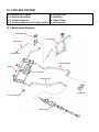
1
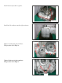
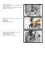
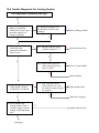
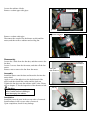
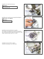
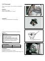
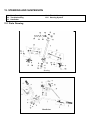
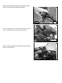
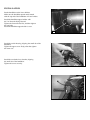
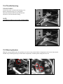
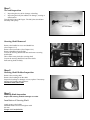
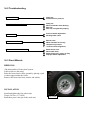
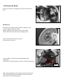
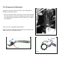
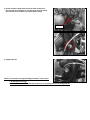
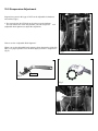
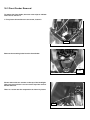
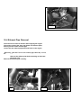
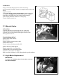
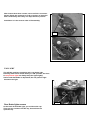
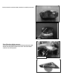
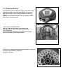
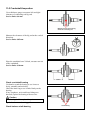
11-5 Crankshaft Inspection
Use a thickness gauge to measure left and right
clearance of connecting rod big end.
Service limit: 0.6 mm
Measure point for the crank big
end of the connecting rod.
Measure the clearance of the big end at the vertical
directions.
Service limit: 0.05 mm
Place the crankshaft on a V-block, measure run-out
of the crankshaft.
Service limit: 0.10 mm
90 mm
60 mm
Check crankshaft bearing
Use hand to crank the bearing to see it moves
freely, smoothly and noiseless.
Check the inner ring to see it links firmly on the
bearing.
If any roughness, noise and loose linkage are
detected, replace the bearing with new one.
Caution
The bearing shall be replaced in pair.
Special tool: outer bearing puller
Check balance shaft bearing
Crank bearing
Check bearings on right and left crankcase.
Rotate each bearings inner ring with fingers.
Check if bearings can be turned in smooth and silent,
and also check if bearing outer ring is mounted on
gear tightly.
If bearing rotation is uneven, noising, or loose bearing
mounted, then replace it.
Special tool: Inner bearing puller
Bearing driver
Balance shaft bearings
11-6 Assembly Of Crankcase
Install wave washer into right crank bearing seat.
Wave washer
Install crank shaft on the right crankcase.
Align the position mark on the balance shaft drive
gear with that of balance shaft driven gear, and then
install balance shaft onto right crankcase.
Position mark
Install 2 dowel pins and new gasket.
Dowel pins
Install the left crankcase onto the right crankcase.
11 bolts
Tighten 11 bolts on the left crankcase.
Torque value: 0.8~1.2kgf-m
Tighten 2 bolts on the right crankcase.
Torque value: 0.8~1.2kgf-m
2 bolts
Clean the crankshaft.
Apply a layer of grease on the lip of oil seal, Puts on
the left crank shaft.
Install the oil seal in the left crankcase with care not to
damage the lip of the oil seal.
By oil seal driver (27×42×7), oil seal will knock into
located.
Special tool:
Oil seal driver (27×42×7)
Oil seal
driver
Tensioner
Install the tensioner and tighten the pivot bolt.
Torque value: 0.8 ~1.2kgf-m
Install the cam chain.
Install the cam chain setting plate.
Cam chain setting plate
12. COOLING SYSTEM
12-1 Mechanism Diagram
12-2 General Information
12-3 Trouble Diagnosis
12-4 Trouble Diagnosis For Cooling System
12-5 System Test
12-6 Radiator
12-7 Water Pump
12-8 Thermostat
12-1 Mechanism Diagram
Radiator filler cap
Reserve tank
By-pass pipe
To cylinder head
Coolant outlet pipe
Radiator
Cooling fan
Coolant inlet pipe
Thermostat
Thermo switch (fan)
Water pump
12-2 General Information
General
Warning:
While the engine is running, never attempt to open the radiator filler cap, the pressurized hot coolant
may shoot out and cause serious scalding injury. No maintenance work is allowed to perform unless the
engine is completely cooled down.
y
y
y
y
y
y
Refill the radiator with distilled water or specified additives.
Add coolant to the reservoir.
The cooling system can be serviced on the ATV.
Never spill the coolant to the painted surface.
Test the cooling system for any leakage after the repair.
Please refer to Section 17 for inspection of the temperature sensor switch for the fan motor and the water
thermometer.
Technical Specification
Item
Specification
0.9±0.15 kgf/cm2
850c.c.
420c.c.
Begins to activate at 82~95к
Stroke: 0.05~3mm
Begins to activate at 98±3к
Not-pressure: 107.7к
Pressurized: 125.6к
Pressure to open filler cap
Capacity of coolant: Engine + radiator
Reservoir upper
Thermostat
Thermos switch (fan)
Boiling point
Torque Value
For water pump rotor
1.0~1.4kgf-m
Tools Requirement
Special tools
Water pump bearing driver (6901): SYM-9100100
Water pump oil seal driver (Inner): SYM-9120500-H9A
Water pump mechanical seal driver: SYM-1721700-H9A
Inner bearing puller: SYM-6204020
12-3 Trouble Diagnosis
The engine temperature is too high
y The water thermometer and the temperature
sensor do not work properly.
y The thermostat is stuck to close.
y Insufficient coolant.
y The water hose and jacket are clogged.
y Fan motor malfunction.
y The filler cap of the radiator malfunction.
The engine temperature is too low
y The water thermometer and the temperature
sensor malfunction.
y The thermostat is stuck to open.
Coolant is leaking
y The water pump mechanical seal does not
function properly.
y The O ring is deteriorated.
y The water hose is broken or aged.
12-4 Trouble Diagnosis For Cooling System
The temperature indicated is too high
Y
A. Stop and waiting for the
engine is completely
cooled down, open cap to
check the capacity of
coolant in radiator.
A1.Refill the radiator with
coolant then check for any
leakage?
N
Y
Water leaking problem
N
Y
B. Turn on main switch and
check the water
temperature indicator
back to zero?
N
B-1. Measure thermo unit to
confirm voltage 6VХ?
N
Replace thermo unit
Y
Y
B-2. Inspect the circuits of
water temperature have
short or earth?
Y
Short or earth handle
N
Meter problem
C. Open radiator cap and
softly throttle, inspect
coolant have circulated?
C-1. Eng. stop and remove
water pump cover, start
the motor to inspect pump
its rotation?
N
Y
Y
D. Close radiator cap,
measure thermo unit to
confirm voltage reduced
comply with temperature
rise?
Y
Next page
Water pump repair
N
Water hose clogged
N
Replace thermo unit
Preceding page
E. Keep eng. 3000~4000 rpm
and inspect cooling fan was
operating after the
temperature gauge over 3
checks?
N
E-1. Measure thermal switch
to confirm voltage be
changed (12Ш0V)?
N
Replace thermal switch
Y
Y
F. Confirm the cooling fan was
convulsion?
E-2. Connect cooling fan
terminals with battery
(12V) directly to inspect
its operation?
N
Replace cooling fan
Y
Meter unusual
Y
If circuit connects reverse
cooling fan will forward,
correct and check again.
E-3. Keep eng. 3000~4000
rpm and inspect coolant
flow into reserve tank
after the temperature
gauge over 3 checks?
Y
E-4. Remove thermostat from
holder then heats it by
water directly to check its
operation?
Y
For bleed the air bubbles
completely, open radiator cap
and start engine while engine is
cool then press water hose
softly by hand to bleeding.
Turn the throttle repeatedly
until the coolant surface
becomes stable.
N
Replace thermostat
Refill with coolant then
check again
Notice the water hose
can’t any unsuitable
bend or twist and
bleed the air bubbles
completely.
12-5 System Test
Test on the filler cap
Hermetically seal the filler cap, apply water and pressure
to the filler cap. Replace it with new one if found failing to
maintain the specified pressure within a given time limit,
or the opening pressure is too high or too low. The
specified pressure shall be maintained at least for 6
seconds in the test
Relief pressure for the filler cap: 0.9-0.15 kgf/cm2
Apply pressure to the radiator, engine and water hose to
check for any leakage
Pressure tester
Filler cap
Caution
Pressure which is too high may damage the radiator.
Never use pressure which exceeds 1.05 kg/cm2.
Reserve tank cap
If the system fails to maintain the specified pressure for at
least 6 seconds, repair or replace parts.
Change of coolant
Warning
Never attempt to carry out service work on the
cooling system unless the engine is completely
cooled down, otherwise, you may get scalded.
Radiator filler cap
Remove the front center cover, and then remove filler cap.
Place a water pan under the water pump; loosen the drain
bolt to drain out the coolant.
Reinstall the drain bolt.
Refilling system with coolant and bleeding the air bubbles.
y Run the engine, and remove by-pass pipe.
y Check by-pass hole whether has the air bubble to emit.
y If emits without the air bubble, only has the coolant to
flow out, then backflow pipe joint on, engine flameout.
y Remove radiator filler cap.
y Starts the engine, inspects does not have the air bubble
in the radiator coolant, also the coolant liquid level is
stable.
y Stop the engine. Add coolant to proper level if
necessary.
y Screw and tighten up the radiator filler cap.
Caution
In order to avoid the water tank rusting, please do
not use the unclear trade mark refrigerant.
Coolant recommended: SYM Bramax radiator agent.
Concentration: 50%
Drain bolt
By-pass pipe
Check reserve tank
y Remove the front center cover, and then remove reserve
tank filler cap.
y Check the liquid level in the front fender right side. Add
coolant to proper level if too low.
y Reinstall the reserve tank filler cap.
Caution
The reserve tank liquid level coca too is not high,
after avoids the water temperature elevating, in
the cooling system the refrigerant backflow
floods.
Upper
Lower
12-6 Radiator
Check
Remove the front center cover, side covers and front fender.
(refer chapter 13), check for any leakage from weld seam.
Blow radiator clean using compressed air. If the radiator is
blocked by dirt, use low pressure water jet to clean it.
Care shall be taken when straightening the sink fan.
Removal
Place a water pan under the water pump; loosen the drain
bolt to drain out the coolant.
Drain bolt
Remove coolant filler pipe.
Filler pipe clamp
Loosen the radiator 4 bolts.
Remove coolant upper side pipes.
Coolant inlet pipe
4 bolts
Coolant outlet pipe
Remove coolant outlet pipe.
Disconnect the couplers for the thermo switch and fan
motor, and then remove radiator and cooling fan.
Thermo switch coupler
Disassembly
Loosen the 3 bolts from the fan duct, and then remove the
fan duct.
Loosen 3 screws from the fan motor, and take off the fan
motor.
Remove nut to remove the fan from fan motor.
Cooling fan
duct bolts x3
Cooling fan
motor screws x3
Assembly
Install fan motor onto fan duct and insert the fan into the
motor shaft.
Apply a coat of the adhesive to the shaft thread of the
motor, and then install the washer and the lock nut.
Tighten the fan duct onto the radiator with 3 bolts. Please
refer to chapter 17 for the inspection of the thermo switch.
Caution
Liquid packing must be applied to the
thermo switch before installing to
avoid damaging the radiator.
Installation
Install the removed parts in the reverse order of removal.
Install radiator in the reverse order of removal.
Upon completion, check for any leakage.
Thermo switch
Fan nut
12-7 Water Pump
Check water pump seal / cooling system divulges
inspection
y Disassembles the refrigerant drain bolt, overflows little
buckles the N actually fluid, confirmed overflows the
refrigerant whether has the greasy dirt.
y Turns on lathe the engine oil gauge rule, the inspection
engine oil whether does have bleaches situation of the
emulsified.
If has the above two kind of interior to divulge the
phenomenon, possibly for the water pump inner two seal
damages, the engine cooling system damages or the
cylinder and the cylinder head gasket damages, please first
dismantles the right crank case to say A confirms the
replacement water pump seal, if does not have the question
to take apart for overhaul cooling system of system again
the cylinder head, the cylinder.
Removal of water pump
Loosen the drain bolt to drain out the coolant.
Remove the water hose.
Loosen 4 bolts and remove the pump cover.
Loosen 9 bolts and remove the right cover.
Take off the gasket and dowel pins.
Turn pump rotor clockwise and remove.
Caution
The rotor is provided with left turn
thread.
Remove the cir clip from the right crankcase cover.
Remove the water pump shaft and the inner bearing.
Remove the outside bearing by inner bearing puller.
Rotate the inner ring of bearing, the bearing shall move
smoothly and quietly.
If the bearing does not rotate smoothly or produces a noise,
replace it with new one.
Special tool:
Inner bearing puller
Drain bolt
Check any wear and damage of the mechanical seal and
inside seal.
Mechanical seal
Caution
The mechanical seal and inside
seal must be replaced as a unit.
Replacement of Mechanical Seal
Remove the inside bearing by inner bearing puller.
Drive the mechanical seal and inner seal out of the right
crankcase.
Special tools:
Inner bearing puller
Water pump bearing driver
Water pump bearing
driver
Caution
Replace a new mechanical seal after removing
it.
Mechanical seal
Apply a coat of sealant to the mating surfaces of the right
crankcase before installing the new mechanical seal.
Install the mechanical seal onto the right crankcase.
Special tools:
Water pump mechanical seal driver
Water pump mechanical
seal driver
Install the new inner seal onto the right crankcase.
Special tools:
Water pump oil seal driver (inner)
Install a new outside bearing to the right crankcase cover.
Special tools:
Water pump bearing driver (6901)
Water pump oil seal
driver (inner)
Water pump bearing
driver (6901)
Caution
Do not reuse old bearing. It must be
replaced with a new one once it has
been removed.
Inner bearing
Mount the water pump shaft and the inner bearing to the
right crankcase cover.
Water pump shaft
Install the cir clip to hold the inner bearing.
Install the seal washer into the rotor.
Caution
Washer must be replaced together with
the mechanical seal.
Install the rotor onto the water pump shaft and tighten.
Torque Value: 1.0~1.4kgf-m
Caution
The rotor is left thread.
Install the dowel pin and right cover gasket.
The rotation water pump rotor, causes the water pump
drive shaft scoop channel, aligns the oil pump drive shaft
flange, install the right crank case. (9 bolts)
Install the dowel pin and new gasket.
Install the water pump cover with 4 bolts.
Water pump rotor
12-8 Thermostat
Temperature sensor
Please refer to chapter 17 for inspection of temperature
sensor.
Removal
Drain out the coolant.
Remove the thermostat set. (2 bolts)
2 Bolts
Inspection
Visually inspect thermostat for any damage.
Place the thermostat into heated water to check its
operation.
Caution
Whenever the thermostat and the
thermometer are in contact to the wall of
heated water container
the reading displayed is incorrect. If the
valve of the thermostat remains open at
room temperature or the valve operation is
not corresponding to the temperature
change
then it must be replaced.
Technical Data
Valve begins to open
Valve stroke
82~95к
0.05 ~ 3mm
Installation
Install the thermostat.
Install the thermostat cover. (2 bolts)
Refill the coolant and bleed out the air bubble (Page 12-5).
By-pass pipe
13. STEERING AND SUSPENSION
13-1 Parts Drawing
13-2 Troubleshooting
13-3 Handlebar
13-4 Throttle Housing
13-5 Steering System
13-1 Parts Drawing
Steering
Handle bar
13-2 Troubleshooting
Ϫ
Ϫ
Ϫ
Ϫ
Ϫ
Faulty tire
Steering shaft holder too tight
Insufficient tire pressure
Faulty steering shaft bushing
Damaged steering shaft bushing
Ϫ
Ϫ
Ϫ
Ϫ
Faulty tire
Worn front brake drum bearing
Bent rim
Axle nut not tightened properly
Ϫ
Ϫ
Ϫ
Ϫ
Ϫ
Ϫʳ
Bent tie rods
Wheel installed incorrectly
Unequal tire pressure
Bent frame
Worn swing arm pivot bushings
Incorrect wheel alignment
FRONT SUSPENSION NOISE
Ϫ
Ϫ
Loose front suspension fasteners
Binding suspension link
HARD SUSPENSION
Ϫ
Ϫ
Ϫ
Faulty front swing arm bushings
Improperly installed front swing arms
Bent front shock absorber swing rod
SOFT SUSPENSION
Ϫ Weak front shock absorber springs
Ϫʳ Worn or damage front swing arm bushings
HARD STEERING
FRONT WHEEL WOBBLING
STEERS TO ONE SIDE
13-3 Handlebar
REMOVAL
Remove the throttle housing by
two fixed screws.
Remove the throttle lever housing on the right
side handle bar.
Remove brake lever bracket assembly.
Screws
Remove the handle bar switch on the left handle bar.
Remove rear brake lever bracket assembly.
Screws
Bolts
Remove the handle cover and instrument panel by four
screws at right and left side as shown in picture.
Screws
Remove the bolts attaching the handlebar upper holder.
Remove the handlebar.
INSTALLATION
Put the handlebar on the lower holders.
Make sure the handlebar punch marks match
with the top end of the handlebar of lower holders.
Install the handlebar upper holders with
the L or R marks facing forward.
Tighten the forward bolts first, and then tighten
the rear bolts.
Install the handlebar upper holder’s cover.
dot
Install the switch housing, aligning the small dot of the
handlebar.
Tighten the upper screw firstly, after that tighten
the lower one.
Install the rear brake lever bracket, aligning
the small dot of the handlebar.
Tighten the screw securely.
13-4 Throttle Housing
DISASSEMBLY
Loosen the screws on the throttle housing cover.
Remove throttle housing cover and gasket.
Disconnect throttle cable from the throttle arm
and remove from the throttle housing.
NOTE:
Assembly is in the reverse order of disassembly.
Screws
13-5 Steering System
When the steering shaft needs to be repaired, you need to remove three kinds of components: the tie-rods, front wheels
and hub assy. Following the steps to check these components, if broken please change the new one
Step 1
Tie-rod Inspection
9
9
Inspecting the tie-rod for damage or bending.
Inspecting the ball joint rubbers for damage, wearing or
deterioration.
Turn the ball joints with fingers. The ball joints should turn
smoothly and quietly.
Steering Shaft Removal
Remove the handle bar cover and handle bar.
(See Chapter 13-3)
Remove the front fender. (See Chapter 16-1)
Remove handlebar lower holder.
Loosen the steering shaft holder bolt and remove steering
shaft holder.
Take off the cotter pin below steering shaft.
Loosen the steering shaft fixed out below shaft.
Pull steering shaft carefully.
Step 2
Steering Shaft Holder Inspection
Remove the steering shaft.
Remove the bushing from the shaft.
Inspect the bushing for damage or wear, replace if necessary.
Measure the bushing inner diameter.
Maximum limit: Ø39.5 mm
Step 3
Steering Shaft Inspection
Inspect the steering shaft for damage or cracks.
Installation of Steering Shaft
Apply grease to the holder.
Install the holder and oil seal tighten with
the nuts.
Torque: 33 N.m (24 lbf-ft)
Install the steering shaft nut and tighten it.
This nut is under this steering shaft.
Torque: 50 N.m (37 lbf.ft)
14. FRONT WHEEL AND BRAKE SYSTEM
14-1 Parts Drawing
14-2 Troubleshooting
14-3 Front Wheels
14-4 Hydraulic Brake
14-5 Suspension Adjustment
14-1 Parts Drawing
FRONT WHEEL
FRONT BEAKE
14-2 Troubleshooting
HARD STEERING
Ϫ
Ϫ
Faulty tire
Insufficient tire pressure
FRONT WHEEL WOBBLING
Ϫ
Ϫ
Ϫ
Ϫ
Faulty tire
Worn front brake drum bearing
Bent rim
Axle nut not tightened properly
BRAKE DRAG
Ϫ
Ϫ
Incorrect brake adjustment
Sticking brake cable
STEERS TO ONE SIDE
Ϫ Bent tie rods
Ϫ Wheel installed incorrectly
Ϫ Unequal tire pressure
Ϫʳ Incorrect wheel alignment
POOR BRAKE PERFORMANCE
Ϫ
Ϫ
Ϫ
Ϫ
Brake shoes worn
Worn brake drum
Brake linings oily, greasy or dirty
Improper brake adjustment
14-3 Front Wheels
REMOVAL
(The disassemble of front wheel system
in this serials are the same)
Raise the front wheels off the ground by placing a jack
or other support under the frame.
Remove the front wheel nuts, washer and wheels.
INSTALLATION
Install and tighten the four-wheel nuts
Torque: 24 N.m (17.7 lbf.ft)
Remember put a cotter pin in the castle nut.
Wheel nuts
14-4 Hydraulic Brake
This type of brakes are applying in front of two wheels of
RA1
REMOVAL
Raise the front wheels off the ground by placing a jack
or other support under the frame.
Remove the front wheel nuts, washer and wheels.
Please follow the next three steps of right pictures.
Loosen fours nuts as shown in picutre
Then take the wheel out.
you can find two bolts fixed at front hydraulic disk
component.
Loosen these two bolts and you can take out disk component.
Bolts
After disassembling the wheel, please inspect the disk plate.
If the disk plate needs to be changed, you have to loosen
castle nut to take wheel hub apart.
Before loosening castle nut, you have to remove cotter pin
Wheel hub
Castle nut
Then using the power tools to take the screw out
from brake stopping plate. You can take the brake disc off.
When change brake shoe wear, you must push
the master piston to rearward.
After removal the front brake assembly, you must fabricate
in reverse sequence.
ADD BRAKE OIL
The brake oil tank is under the driver seat at right hand side.
Please check the brake oil level position at outside of tank.
To open the cap of brake oil tank, please turn “CCW”
direction.
Brake oil tank
14-5 Suspension Adjustment
Suspension system in this type of AVT can be adjustable its
hardness and softness (fig 1).
1. You can raise the all ATV body up by using a repair platform.
The four wheels are in the free position, you can use special
tool (adjustable hook spanner, E1105-LRA0-FT1 ) to adjust
the suspension.
How to use the “Adjustable Hook Spanner”
When you use the adjustable hook spanner, please depress the
slider (fig 2&3.) to a proper position.
Fig 1
Depress
Fig 2
Depress
Fig 3
15. REAR WHEEL AND BRAKE SYSTEM
15-1 Parts Drawing
15-2 Troubleshooting
15-3 Remove Rear Wheel And Rear Brake
15-4 Swingarm & Rear Axle Holder
15-5 Suspension Adjustment
15-1 Parts Drawing
REAR WHEEL
REAR Wheel Axel
REAR BRAKE
15-2 Troubleshooting
Bad Brake Performance
Vibration or Wobble
Brake Drag
Hard Suspension
Soft Suspension
Ϫ Brake shoes are worn
Ϫ Bad brake adjustment
Ϫ Brake linings are oily, greasy or dirty
Ϫ Brake drums are worn
Ϫ Brake arm setting is improperly engage
Ϫ Axle is not tightened well
Ϫ Bent rim
Ϫ Axle bearings are worn
Ϫ Faulty tires
Ϫ Rear axle bearing holder is faulty
Ϫ Incorrect brake adjustment
Ϫ Sticking brake cam
Ϫ Sticking brake cable
Ϫ Bent damper rod
Ϫ Faulty swing arm pivot bushings
Ϫ Weak shock absorber damper
Ϫ Weak shock absorber spring
15-3 Remove Rear Wheel And Rear Brake
To replace brake disk
The produce of removing the rear left tire is same as
removing front tire.
You need to loosen four nuts firstly.
Loosen two bolts to take out rear brake disk
as shown in picture.
Bolts
Loosen bolts and remove the brake disc
Check the thickness of disc and replace a new one
if the thickness less than 3mm
TO REPLACE THE BRAKE SHOE
To replace the brake shoe, please loosen this bolt as
shown in picture.
Bolt
Please push the plate back to take a shoe out as shown
in picture
Plate
Piston
Eventually, you can take all brake shoe out the hub.
There are two kind of brake linings as shown in picture
TO REPLACE THE BRAKE HYDRAULIC OIL
Loosen the bolts and open the cover
Loosen the bolt and drain the used oil out.
Tighten the bolt after the used oil being drained out
completely
Bolt
Add the brake oil (Dot 3 or Dot 4)
Keep oil level at least half of the cup in order to avoid
air in the brake system.
Loosen the bolt to vent the air from brake system.
Tighten the bolt if there isn’t any air in the brake system
Tighten torque 40~70kgf-cm
Pull left brake lever slightly in order to extract air from
brake system
Fill the brake oil in the level shown on the cup
when no air comes out
Assemble the cover
15-4 Swingarm & Rear Axle Holder
This section is to introduce how to repair the swing-arm,
The following pictures are going to teach you how to
Install the swing-arm.
1. Put the swingarm at proper position as shown in
picture. Two hanger bolts will be used to hold the swing-arm
at right and left side.
Hanger bolt
2. Tighten a hanger bolt on the right side as shown in
picture.
Hanger bolt
Swingarm
3. Screw another hanger bolt on the left side as shown in
picture. But do not tighten it. Let the cross-section of bolt
and cross-section of hole in the same plane nearly.
Hanger bolt
4. Tighten the nut
NOTE: If you make a wrong assembly procedure, it will cause:
1. A damage of bearings
2. The main frame will be extended at the area of assembly swim arm (Unalignment).
15-5 Suspension Adjustment
Suspension system in this type of AVT can be adjustable its hardness
and softness (fig 1).
1. You can raise the all ATV body up by using a repair platform.
The four wheels are in the free position, you can use special
tool
(adjustable hook spanner) to adjust the suspension.
How to use the “Adjustable Hook Spanner”
When you use the adjustable hook spanner, please depress the slider (fig
2&3.) to a proper position. You can then adjust your ATV’s suspension
(fig 4).
Fig 1
Press it
Fig 2
Fig 3
Fig 4
16. FENDERS AND EXHAUST PIPE
16-1 Fenders Drawing
16-2 Rear Fenders Removal
16-1 Fenders Drawing
EXHAUST PIPE (For all serials)
16-3 Front Fender Removal
16-4 Exhaust Pipe Removal
16-2 Rear Fenders Removal
There are two seat release bars located at the right
and left hand side of the seat. Please remove the seat first.
Release Bars
Procedures of remove the rear fender:
Remove the rear rack.
1. Open the seat.
2. Loosen the four bolts which connect the front fender and
rear fender.
3. Loosen the two bolts, which connect the rear tender
and frame, these two bolts just below the seat.
Screws
Loosen the three screws which connect with footrest plate.
Pull the rear fender backward.
So the rear fender can be removed.
Screws
Pull the seat handle up first.
Bolts
There are two screws on the top of seat compartment.
Please remove them.
Bolts
Next, there are two screws on side of the tail.
Screw
Finally, you must remove the bolts on the footrest.
Bolts
16-3 Front Fender Removal
To remove the front fender, there are sever trips to indicate
users how to remove it.
1. First picture shows there are two screw, loosen it.
Screws
Remove the mounting bolts from the front fender.
Bolts
Please remove the two screws on the top of the headlight.
Then you can see there is a screw on the tip of the vehicle.
Please remove it.
There is a screw near the suspension as shown in picture.
Bolt
Screws
16-4 Exhaust Pipe Removal
You must wait at least 15 minutes after stopping the engine.
You need to remove the seat, rear fender and footrest plate,
before you take off the exhaust pipe.
Loosen the two exhaust pipe bolts that fixed on the engine.
WarningΚDO NOT service the exhaust pipe while they are hot.
Remove the exhaust pipe bolts mounting on the frame
below the seat.
Remove the exhaust pipe carefully.
Nuts
Bolts
Bolt
EXHAUST PIPE INSTALLATION
Installation is the reverse order of removal.
Torque: Exhaust muffler bolts 30 N.m (22 lbf.ft)
CATUATION:
After installing, make sure that there are no exhaust leaks.
17. ELECTRICAL SYSTEM
17-1
17-2
17-3
17-4
Troubleshooting
Ignition Coil
Ignition Timing
Battery Information
17-5
17-6
17-7
17-8
Electric Starter
Light Bulbs Replacement
Instrument Pane
Wiring Diagram
17-1 Troubleshooting
ENGINE STARTS BUT STOPS
NO SPARK AT PLUG
ENGINE STARTS BUT RUNS POORLY
CHARGING SYSTEM FAILURE
Ϫ IMPROPER IGNITION TIMING
Ϫ FAULTY SPARK PLUG
Ϫ ENGINE STOP SWITCH AT “ OFF “ POSTION
Ϫ GEARSHIFT BAR IS NOT AT NORMAL
POSITION
Ϫ FAULTY IGNITION COIL
Ϫ FAULTY GENERATOR
Ϫ FAULTY CDI UNIT
Ϫ POOLY CONNECTED:
Between CDI and ignition coil
Between alternator and CDI unit
Between CDI and engine stop switch
Between ignition coil and spark plug
Between generator and CDI unit
Ϫ IGNITION PRIMARY CIRCUIT
Faulty generator
Faulty CDI unit
Faulty alternator exciter coil
Loosen contacted terminals
Faulty ignition coil
Ϫ IGNITION SECONDARY CIRCUIT
Faulty plug
Loosen contacted spark plug wire
Ϫ IMPROPER IGNITION TIMING
Faulty generator
Faulty CDI unit
Ϫ LOOSE, BROKEN OR SHORTED WIRE
Ϫ FAULTY ALTERNATOR
Ϫ FAULTY IGNITION SWITCH
ENGINE INTERMITTENT POWER
Ϫ LOOSE BATTERY CONNECTION
Ϫ LOOSE CHARGING SYSTEM CONNECTION
STARTER MOTOR CAN NOT WORK
Ϫ BATTERY SHORTAGE
Ϫ FAULTY IGNITION SWITCH
Ϫ LOOSE OR DISCONNECTED WIRE
Ϫ FAULTY IGNITION SYSTEM
Ϫ ENGINE PROBLEMS
Ϫ FAULTY ENGINE STOP SWITCH
Ϫ THE SWITCH DO NOT TURN TO “ON”
POSITION
ENGINE CAN NOT WORK
HEAD LIGHT CAN NOT WORK
Ϫ THE LIGHT BULB WAS BROKEN, REPLACED
17-2 Ignition Coil
Remove the spark plug cap from the spark plug.
Disconnect the ignition coil primary wire.
Measure the primary coil resistance.
STANDARD: 0.1 - 0.3Ө(20к)
Measure the secondary coil resistance with
the spark plug cap in place.
STANDARD : 7.4 – 12 kӨ(20к)
17-3 Ignition Timing
The ignition advance is 15̓̈́ 3̓/4000rpm
The Capacitive Discharge Ignition (CDI) system is factory pre-set and does not require adjustment.
17-4 Battery Information
The battery gives off explosive gases; keep sparks, flames and cigarettes away. Provide adequate
ventilation when charging or using the battery in an open area. The battery contains sulfuric acid
(Electrolyte). Contact with skin or eyes may cause severe burns. Wear protective clothing and a face shield.
Electrolyte is poisonous. If swallowed drink large quantities of water or milk and call a physician.
BATTERY VOLTAGE INSPECTION
Battery is under the seat. Measure the battery voltage by
using a multifunction electric meter.
VOLTAGE: Fully charged: 13.1 V
Undercharged: Below 12.0 V
BATTERY REMOVAL
There are two main steps to teach you how to take out battery.
Open the seat, and then you can see the battery.
Disconnect the negative cable (Black Ё ) first and then the
positive cable (Red Ѐ ).
BATTERY INSTALLATION
Install the battery in the reverse order of removal.
After installing the battery, coat the terminals with
clean grease.
Bolts
CHARGING
Firstly, connect the charged positive cable to the battery
positive terminal. Secondly, connect the charged negative cable to the
battery
negative terminal.
Using 0.9A-charging current about 11 hours. (Normal charging)
Or using 4A-charging current about 3 hour. (Quick charging)
Keep flames and sparks away from a battery being charged.
Quick charging should be limited to an emergency;
Normal charging is preferred.
17-5 Electric Starter
Information
If a battery has not work a period of time, the voltage may
reduce and may not provide enough power to starter motor.
If a battery is in a good condition, but engine can not be start.
Please go back to service.
TROUBLESHOOTING
Starter Motor Turns Slowly
Weak battery.
Poorly connected starter motor cable.
Failed starter motor.
Poorly connected battery ground cable.
Starter Motor Cannot Work
Engine stop switch at “off “position.
Gearshift bar is not at neutral position.
Check for a blown fuse near battery.
Make sure that the battery is fully charged and in good condition.
17-6 Light Bulbs Replacement
HEADLIGHT
To remove the headlight, please loosen three screws at
back of the headlight.
After loosen these three screws, users can find a connector.
Please disjoin the connector in order to replace an electrical
bulb conveniently and safely. The steps show on pictures.
Installation is in the reverse order of disassembly.
Screws
TAILLIGHT
The taillight combines a position and a rear brake light.
Normally, when users switch the key to “ON” position, the front
& rear position lights are always keep the light slightly.
Until a brake handlebar is depressed, the rear position light
become more light
Taillight
Rear Brake lights remove
On the back of the brake light, you could see the cap.
There are two screws to fix this cap, loosen them can
open the cap.
Please rotate the electrical bulb, and then it could be removed.
Screws
Rear Direction lights remove
The same disassembling procedure like front direction light.
Please use the pliers to remove the seat. Then the bubble
could be see and replaced.
Rear Brake Lights
17-7 Instrument Pane
The instrument panel includes fuel gauge, speed meter, water
Temperature gauge, right and left turn signal, trip do-meter,
and indicator camp. A LCD is used on ATV8E’s instrument
panel
to display all driving information for users. Therefore, this is
an all-in-one instrument panel.
Instrument Panel REMOVAL
There is a cable and connector on the back of the
instrument panel. After removing instrument panel,
users can find out
an electrical connector which is connected with a driving
sensor at the back of the instrument panel.
The sensor is installed at the brake disk and a cable is tightened
on the left side of knuckle component
as shown in pictures
Sensor
Cable
17-8 Wiring Diagram
18.TROUBLESHOOTING
18.4 Loss Power
18.5 Poor Handling
18-1 Engine Can Not Work
18.2 Poor Performance At Low And Idle Speeds
18.3 Poor Performance At High Speed
18-1 Engine Can Not Work
Possibility
N.G.
CHECK FUEL FLOW TO CARBURETOR
Ϫ No fuel In fuel tank
Ϫ Clogged float valve
Ϫ Clogged fuel tank cap breather hole
Ϫ Clogged at fuel tube
O.K.
N.G.
SPARK TEST
WEEK OR NO SPARK
O.K.
N.G.
TEST CYLINDER COMPRESSION
LOW COMPRESSION
O.K.
Ϫ
Ϫ
Ϫ
Ϫ
Ϫ
Ϫ
Ϫ
Ϫ
Ϫ
Ϫ
Faulty spark plug
Fouled spark plug
Faulty CDI unit
Faulty alternator
Faulty engine stop switch
Poorly connected ,broken or shorted wires
Broken or shorted ignition coil
Broken or shorted spark plug wire
Faulty pulse generator
Faulty ignition switch
Ϫ Worn cylinder and piston rings
Ϫʳ Damaged cylinder head gasket
ENGINE START BUT STOPS
START THE ENGING
ENGINE DOES NOT FIRE
REMOVE AND INSPECT SPARK PLUG
WET PLUG
Ϫ
Ϫ
Ϫ
Ϫ
Ϫ
Auto choke off or damaged
Auto choke power wire disconnected
Improperly adjusted air screw
Improperly ignition timing
Fuel / air mixture ratio is too lean
Ϫ Carburetor flooded
Ϫ Improperly adjusted air screw
Ϫ Fuel / air mixture ratio too rich
Ϫ Auto choke stuck or damaged
Ϫ Air cleaner dirty
18.2 Poor Performance At Low And Idle Speeds
Possibility
N.G.
CHECK IGNITION TIMING
.
Faulty CDI unit or pulse generator
.
Improperly adjusted air screw
.
.
Deteriorated insulator o-ring
Loose carburetor
.
.
.
.
.
.
.
.
.
Loose or disconnected ignition system wires
Faulty ,carbon or wet fouled spark plug
Faulty alternator
Faulty CDI unit
Faulty ignition switch
Faulty ignition coil
Faulty pulse generator
Broken or shorted spark plug wire
Faulty engine stop switch
O.K.
CHECK carburetor
AIR SCREW ADJUSTMENT
N.G.
O.K
CHECK FOR LEAKING
INTAKE PIPE
N.G
O.K.
PERFORM SPARK TEST
WEEK OR INTERMITTENT
SPARK
18.3 Poor Performance At High Speed
Possibility
N.G.
.
.
Faulty CDI unit
Faulty pulse generator
.
.
.
.
Lack of fuel in tank
Clogged fuel line
Clogged fuel valve
Logged fuel tank breather hole
CLOGGED
.
Clean with high pressure air gun
DIRTY
.
Clean the filter
CHECK IGNITION TIMING
O.K.
CHECK FUEL TUBE AT
CARBURETOR
FUEL FLOW RESTRICTED
FUEL FLOWS FREELY
REMOVE CARBURETOR
CHECK FOR CLOGGED JETS
NOT CLOGGED
CHECK AIR CLEANER
FILTER ELEMENT
18-4 Loss Power
Possibility
RAISE WHEELS OFF GROUND
AND SPIN BY HAND
DOES NOT SPIN FREELY
Ϫʳ
Ϫʳ
Ϫʳ
Ϫʳ
SPIN FREELY
PESSURE LOW CHECK
CHECK
TIRE PRESSURE
TIRE
Brake dragging
Drive chain too tight
Damaged wheel bearing
Wheel bearing needs lubrication
Ϫʳ Punctured tire
Ϫʳ Faulty tire valve
PRESSURE NORMAL
ACCELERATE LIGHTY
ENGINE SPEED DOES
NOT INCREASE
ENGINE SPEED INCREASE
N.G.
CHECK IGNITION TIMING
O.K.
Ϫʳ
Ϫʳ
Ϫʳ
Ϫʳ
Ϫʳ
Fuel / air mixture ratio too rich or lean
Clogged in air cleaner
Clogged in muffler
Restricted fuel flow
Clogged fuel tank cap breather hole
Ϫʳ Faulty pulse generator
Ϫʳ Faulty CDI unit
TOO LOW
TEST CYLINDER COMPRESSION
Ϫʳ Leaking head gasket
Ϫʳ Worn cylinder and piston rings
O.K.
CLOGGED
CHECK CARBURETOR
Ϫʳ Clean
O.K.
FOULED OR DISCOLOED
Ϫʳ Clean the spark plug
Ϫʳ Spark plug is incorrect heat range
CHECK SPARK PLUG
O.K.
CHECK FOR ENGINE
OVERHEATING
OVERHEATING
O.K.
ACCELERATE OR RUN
AT HIGH SPEED
KNOCKS
Ϫʳ Excessive carbon deposited in
Combustion chamber
Ϫʳ Wrong type of fuel
Ϫʳ Fuel / air mixture ratio is lean
Ϫʳ Use of poor quality fuel
Ϫʳ
Ϫʳ
Ϫʳ
Ϫʳ
Ϫʳ
worn piston and cylinder
Fuel / air mixture ratio is lean
Wrong type of fuel
Ignition timing too advanced
Excessive carbon deposited in
Combustion chamber
18-5 Poor Handling
Possibility
STEERING IS HEAVY
Ϫʳ Damaged steering bearing
Ϫʳ Damaged steering shaft bushing
ONE WHEEL IS WOBBLING
ღʳ
Ϫʳ
Ϫʳ
Ϫʳ
Ϫʳ
Ϫʳ
Ϫʳ
Bent rim
Improperly installed wheel hub
Excessive wheel bearing play
Bent swingarm
Bent frame
Swing arm pivot bushing excessively
Worn
VEHICLE PULLS TO ONE SIDE
Ϫʳ
Ϫʳ
Ϫʳ
Ϫʳ
Bent tie-rod
Incorrect tie-rod adjustment
Rear tie air pressure incorrect
Improper wheel alignment
Ϫʳ Bent frame