1
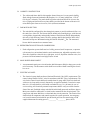
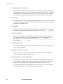
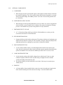
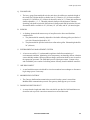
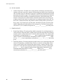
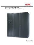
Contents
Overview . . . . . . . . . . . . . . . . . . . . . . . . . . . . . . . . . . . . . . . . . . . . . . . . . . . . . . . . . . . . . . 1
Standard Features . . . . . . . . . . . . . . . . . . . . . . . . . . . . . . . . . . . . . . . . . . . . . . . . . . . . . . . 2
Optional Features . . . . . . . . . . . . . . . . . . . . . . . . . . . . . . . . . . . . . . . . . . . . . . . . . . . . . . . 4
Microprocessor Controller . . . . . . . . . . . . . . . . . . . . . . . . . . . . . . . . . . . . . . . . . . . . . . . . 6
Performance Specifications—Air Cooled . . . . . . . . . . . . . . . . . . . . . . . . . . . . . . . . . . . . 7
Performance Specifications—Water Cooled . . . . . . . . . . . . . . . . . . . . . . . . . . . . . . . . . 9
Performance Specifications—Glycol Cooled . . . . . . . . . . . . . . . . . . . . . . . . . . . . . . . . 11
Electrical Data . . . . . . . . . . . . . . . . . . . . . . . . . . . . . . . . . . . . . . . . . . . . . . . . . . . . . . . . . 13
Dimensional Data . . . . . . . . . . . . . . . . . . . . . . . . . . . . . . . . . . . . . . . . . . . . . . . . . . . . . . 14
Air-Cooled Condensers. . . . . . . . . . . . . . . . . . . . . . . . . . . . . . . . . . . . . . . . . . . . . . . . . . 18
Fluid Coolers . . . . . . . . . . . . . . . . . . . . . . . . . . . . . . . . . . . . . . . . . . . . . . . . . . . . . . . . . . 21
Pump Specifications . . . . . . . . . . . . . . . . . . . . . . . . . . . . . . . . . . . . . . . . . . . . . . . . . . . . 24
Guide Specifications . . . . . . . . . . . . . . . . . . . . . . . . . . . . . . . . . . . . . . . . . . . . . . . . . . . . 27
Guidelines for Installation . . . . . . . . . . . . . . . . . . . . . . . . . . . . . . . . . . . . . . . . . . . . . . . 37
AFX
Model
Module
Configuration
Voltage
Reheat
Humidifier
Air Pattern
AFX
018
M= Main
A= Air Cooled
BA= 208-230/3/60
E= Electric
S= Steam
Humidifier
D= Downflow
W= Water Cooled
KA= 480/3/60
G=Glycol Cooled
MA= 600/3/60
X
XX
065
AFX
XXX
X
APC NetworkAIR™ AFX
U= Upflow
(front return)
X
X
X
i
ii
APC NetworkAIR™ AFX
Overview
The APC NetworkAIR AFX computer room air conditioning system
provides a quiet, efficient, and reliable solution for heat sensitive
equipment areas.
Precision environmental requirements now reach far beyond the
confines of the traditional data center or computer room to encompass
a larger suite of applications,
referred to as technology rooms.
Critical environment applications
include:
Room Air Distribution
Downflow systems discharge air
into the raised floor plenum. These
systems are suitable for areas with
raised floors greater than 12" (305
mm) high. Return air is drawn in
through the top of the system.
Upflow systems discharge air into
either a plenum or ductwork. These
systems are suitable for areas without raised floors, as well as areas
with raised floors. Air is drawn in
through the front of the system.
Standard Features
• Scroll Compressor(s)
• Centrifugal Blower Assembly
• Heavy Gauge Steel Frame
•
•
•
•
•
•
Main Power Circuit Breaker
Microprocessor Controller
Bearing Life, L10 - 200,000 hrs
Front Service Access Only
Pure Steam Canister Humidifier
30% ASHRAE 52.1 Filters
• Three Phase Electric Reheat
• Environmental Monitoring
• Redundant Group Control
• Computer rooms
Configuration
• Telecommunication facilities
• Glycol Cooled
• Clean rooms
• Water Cooled
• Power equipment
• Air Cooled
• Medical equipment rooms
• Archives
• LAN/WAN environments
A worldwide network of APC representatives is fully qualified to
provide engineering, sales, installation and service for our products.
APC warrants all parts for 12
months from shipment. Extended
warranties are available.
• Condensate Pump
Optional Features
• 2 or 3 Way Fluid Regulating
Valves (Water or Glycol)
Compliance Approval
• Brazed Plate Condenser (Water or
Glycol)
• ETL/CETL
• UL Listed to UL 1995 and CSA
C22.2 No. 236
• MEA #223-99-E (City of New
York)
• Plenums (with or without grilles)
• Floorstand (with or without air
deflectors, seismic)
• Discharge Duct Collar
• Downflow Return Duct
• ModBus/JBus Gateway
• OHE Disconnect
C
Models
AFX is available in two models:
AFX18, AFX65.
US
• Spot or Cable Water Detector(s)
• Firestat
• Smoke Detector
• Remote Relay Shutdown
• Reheat/Humidity or Compressor
Lockout
• Remote Display and/or Sensor
• Hot Gas Bypass
• Secondary Drain Pan
• 3-Way Valve Flowswitch
• Custom Alarm Contacts
APC NetworkAIR™ AFX
1
Standard Features
Cabinet
The frame is constructed of heavy
gauge steel for maximum strength.
Steel access panels are insulated for
quieter operation. The unit has been
designed for full service access
from the front. The flush mounted
panels are removable using convenient quarter-turn fasteners. The
access doors for the electronic controller and electrical panel can be
opened without interrupting the
operation of the unit.
Evaporator Coil/Drain Pan
AFX utilizes dual distributors on
one circuit of the refrigeration system. During dehumidification the
smaller distributor is turned off,
effectively reducing the active circuits of the evaporator coil. During
this mode of operation the evaporating temperature is decreased,
resulting in a lower coil surface
temperature. This decreases the
sensible heat ratio of the coil allowing a greater percentage of moisture
removal. Additionally, the warmer
air leaving the inactive circuits of
the evaporator coil blends with the
near saturated air from the active
circuits raising the dry bulb temperature of the blended air well above
saturation. Evaporator is a “V”coil,
1/2” rifled, copper tube, with raised,
lanced, rippled, aluminum fins.
Condensate pan is constructed of
stainless steel.
Humidifier
The humidifier utilizes a pure steam
generator specifically designed for
hi-tech area environmental control.
Pure steam eliminates contaminating mineral deposits, bacteria, white
dust and excessive humidity. Automatic flushing combined with an
indicator that signals when the canister is to be change changed,
ensure maintenance free operation.
2
Electrical Panel
The electrical panel contains the
contactors, starters, overload protection devices, and input power
disconnects. Each wire (except
jumpers) is numbered every 3”
(80mm), or color coded to facilitate
circuit tracing when installing and
servicing the unit. Each AC power
circuit is individually branch circuit
fused on all three phases. All compressor and motor devices are
thermally and short circuit protected. The electrical panel is easily
accessible from the front of the unit.
An emergency cool override switch
can be manually activated to initiate
cooling and a field wired thermostat
can be utilized to control cooling
operation. Electrical components
are UL-listed and -recognized and
all wiring conforms to NFPA 70
(NEC) and UL 1995 requirements.
Air Filter
The filtration of conditioned air is
extremely vital to maintaining the
clean, particle-free environment
required by electrical equipment.
The system uses 30% efficient (100
microns) (ASHRAE 52.1-92), 4”
(102 mm) deep filters, with full
depth pleats. Deeper filters produce
a lower pressure drop, requiring
less energy during normal operation. Filters are replaceable through
the front of the upflow unit and the
top of the downflow unit.
Electric Reheat
A three-phase electrical resistance
heater sized to offset the sensible
cooling capacity in the dehumidification mode is incorporated in each
NetworkAIR AFX. The reheat elements are low watt density sheathed
components. The reheat is 3- phase
to provide even phase loading.
Reheat elements are electrically and
thermally protected. The AFX18 is
one stage and AFX65 is two stages.
APC NetworkAIR™ AFX
Fan/Motor Section
The NetworkAIR AFX includes
centrifugal blower assemblies that
have been engineered for quiet, reliable operation. Lower blower
speeds reduce noise and extend belt
and bearing life to 200,000L10
hours. Permanently lubricated bearings, a single-belt variable pitch
drive, and an adjustable motor base
all ensure dependable operation. In
addition, the return air is evenly distributed across the cooling coil.
Main Power Disconnect
A nonautomatic main power circuit
breaker disconnects all high voltage
power to the unit. The disconnect
switch is accessible without removing the electric box cover.
Refrigeration System and
Compressor
The refrigeration system operates
under an automatic microprocessor
controller for greater efficiency and
accuracy. The heavy-duty compressor is designed for year-round
operation with a 15-year life
expectancy. Performance of the
refrigeration system is enhanced by
use of Scroll Compressor Technology. Vibration in the system is
greatly reduced by eliminating
reciprocating masses found in the
semi-hermetic compressor. Risk of
refrigeration leaks at compressor
gaskets are eliminated with the
compressors’ fully welded hermetic
shell. The design of the scroll is
more tolerant to liquid flood back
than the traditional reciprocating
compressor. Power consumption at
full load is greatly reduced with
higher EER’s of the scroll. In addition reliability is enhanced due to
the fewer moving parts required
using scroll technology. The end
result is a refrigeration system that
offers the user optimized performance, efficiency, and reliability.
Standard Features
Redundant Group Control
Allows up to six NetworkAIR units
the ability to communicate with
each other to automatically switch
upon alarm condition, or timed
rotation. Can also allow standby
units the ability to assist the running
system.
Condensate Pump
The factory-installed and wired
condensate pump will pump 36 gal/
h (0.06 L/s) at 15 ft. (4.6 m) head.
APC NetworkAIR™ AFX
Environmental Monitoring Unit
A stand-alone unit performs contact
monitoring and continuous temperature and humidity sensing through
two probes (one included). The unit
is controlled by available web, control console, or SNMP interface
with a network connection. In the
event of an environmental anomaly,
notification is sent via e-mail or
SNMP. The unit is 18.25” x 9” x
2.75” (464mm x 229mm x 70mm).
3
Optional Features
Condenser
Water- and Glycol-cooled systems
employ a brazed plate condenser
that uses the latest heat transfer
technology. Type 316L stainless
plates are brazed together in a vacuum furnace and comply with
ASME pressure vessel code. Pressure rating is 450 psi (3100 kPa).
Water-Regulating Valve
The Water-and Glycol systems
maintain proper performance by
sensing refrigerant discharge pressure and regulating the among of
water or glycol supplied to the condenser. A two-way or three-way
valve is available. The standard
valve pressure rating is 150 psi
(1030kPa).
Discharge Duct Collar
A 1” (25.4 mm) duct flange is
shipped loose from the factory for
field installation to provide convenient connection to external
ductwork for either supply or return
as needed.
Secondary Drain Pan
Systems are provided with two
drain pans. The primary stainless
steel condensate drain pan lies
directly under the cooling coil. A
secondary emergency drain pan
provides additional protection by
catching and water before it reaches
the subfloor and becomes a
problem.
Spot Water Detector(s)
The solid-state spot water detector
activates an audible alarm on the
controller when moisture is
detected.
Compressor Lockout
Prevents compressor operation in
emergency situations where limited
back-up power is available.
4
Cable Water Detector
A 20 ft. leak detection sensing cable
is placed on the floor or subfloor
around all possible leak sources. If
water or other conductive liquids
contact the cable anywhere along its
length, an alarm is triggered.
Remote Sensor(s)
Environmental sensor(s) can be
strategically placed, up to 50ft.
from the unit to better meet the
site’s cooling needs. The sensor
must be positioned to permit air
movement across the sensors.
Firestat
A firestat is available for factory
installation in the air stream of the
unit. If the return air temperature
reaches 125°F (52°C), an audible
and visual alarm on the microprocessor will be activated and the unit
will immediately shutdown.
Hot Gas Bypass
An auxiliary side-port hot gas
bypass circuit. The activation of the
hot gas bypass circuit will maintain
the evaporator coil temperature during low load conditions. This
optional feature will minimize compressor cycling and temperature
fluctuations.
Smoke Detector
The factory-installed smoke detector is designed to sense smoke in
the return air stream. Upon detection of smoke, an audible and visual
alarm on the microprocessor will be
activated and the unit will be immediately shutdown.
Remote Relay Shutdown
Shutdown of the NetworkAIR system can be done remotely by a
factory installed relay. The relay
can be ordered with a 24V, 120V, or
240V coil. The relay must be powered by others to disable the
NetworkAIR system.
Reheat/Humidity Lockout
When facilities have limited backup
power capacity, this lockout prevents the operation of electrical
loads that are not essential for continued site operation.
Remote Display Panel
The microprocessor controller
allows facility or building maintenance personnel to evaluate and
control the unit from up to 50ft.
away from the unit, without having
to enter the secured space.
APC NetworkAIR™ AFX
3-Way Valve Flow Switch
A Single-Pole, Double-Throw flow
switch can be wired to energize one
device and de-energize another
device powered from the same
source when fluid flow either
exceeds or drops below the set flow
rate.
Air Deflector
A field installed air deflector runs
the length of the unit and attaches to
the floorstand for changing air
direction from vertical to
horizontal.
Plenum
Air discharge plenums are available
with upflow configurations.
Heights are offered in 20” (508mm)
and 24” (610mm). Manually adjustable, double deflecting grilles are
provided on 3 or 4 sides.
OHE Disconnect
A non-fused disconnect switch may
be wired to an outdoor heat
exchanger to disconnect high voltage power if necessary.
Optional Features
Floorstand
The floorstand raises the unit above
the subfloor to match the height of
the raised floor. Heights are available (from 6” (142 mm) to 36” (914
mm)) in 3” (76.2 mm) increments
and are adjustable +/- 1.5” (38.1
mm). APC recommends at least 12”
(305 mm) high floorstands for their
downflow units. Adjustment is provided by threaded pedestals.
Vibration absorbing pads are
included. The floorstand, pedestal,
and pads ship loose. In areas where
earthquakes are a concern, seismic
floorstands are available in 12”
(305mm), 18” (457 mm) and 24”
(610 mm) heights.
Environmental Management
System
A browser-accessible, 1U, rackmountable appliance allows
monitoring of environmental conditions. Monitoring of one
temperature, one humidity, and one
vibration sensor ship standard.
When conditions change, notifications are sent via email to
appropriate personnel. The EMS
provides 8 input contacts, 2 output
relays, and controllable power outlets for defining actions remotely
should conditions warrant it.
ModBus/JBus Gateway
The Gateway translates transmission protocol from the system’s
network into ModBus/JBus communication protocol. One gateway
can support up to 16 units.
APC NetworkAIR™ AFX
Custom Alarm Contact Closures
Each unit is equipped with dry contact closures. Upon activation of the
associated alarm, a discreet Normally open or Normally closed
contact is available for remote monitoring of that discrete alarm.
Downflow Return Duct
A return duct the length and width
of the unit may be field installed on
a downflow unit to provide convenient connection to external
ductwork.
Casters
A set of 6” plated rolling caster
wheels are available for handling of
equipment.
5
Microprocessor Controller
Microprocessor Controller
The microprocessor controller is
standard on the main module of
each system. The controller provides precision control for the
demanding requirements of:
• Data centers
• Control rooms
• Clean rooms
• Switch rooms
• UPS rooms
The easy-to-use display allows the
operator to select options from the
device’s menu-driven interface to
control and monitor the connected
air conditioning system.
Status
Complete status monitoring is provided within the status menu of the
microprocessor controller. Available information includes:
• Current Temperature/Humidity
• Temperature/Humidity Setpoint
Automatic setpoint crossover protection will prevent the setting of
the heat setpoint above the cool setpoint and the humidification
setpoint above the dehumidification
setpoint. Setpoint adjustment can be
restricted to only operators with
knowledge of the security codes set
within the security menu structure.
Configuration
Flexibility is offered through he use
of the configuration menu. Operating requirements are satisfied by
changing the configuration settings. New configurations are
stored in EEPROM and protected
from unauthorized tampering by the
four-digit security password,
selected in the security menu. Configuration options include:
• Fahrenheit or celsius display
• Compressor minimum on/off time
• Power loss restart time delay
• Redundant unit grouping
• Cooling/Heating Status
• Alarm input polarity
• Humidification/Dehumidification
Status
• Alarm enable
Alarms
Quick access to any alarm condition
is facilitated through the menu
structure. The alarm key acts as a
hot key providing immediate access
to the alarm display menu. Presence
of a new alarm will sound the audible alarm. The red alarm LED on
the display panel will remain illuminated until all alarms have been
cleared. The temperature and
humidity alarm setpoints are adjustable. Alarm annunciations include:
• Loss of airflow
• Clogged filter
• High head pressure
• Low suction pressure
• High/Low temperature
• Temperature/Humidity deadbands
• Small room delay
Common Alarm Contact
A common alarm relay is installed
on every microprocessor. In the
event of an alarm condition, the
relay will change state. The user
can select which alarms change the
state of the relay. This feature
allows for remote enunciation of
alarm status.
Run Times
The major components within the
unit have independent run timers
that monitor and store accumulated
run hours on the components. The
run timers are provided with operator adjustable run time alarms.
• High/Low humidity
6
APC NetworkAIR™ AFX
Security
Multiple security levels prevent
unauthorized adjustment of important system parameters. The user
may select a four-digit password for
setpoint and configuration changes.
Should the password be forgotten,
APC can provide temporary access.
Monitoring
With the addition of a supervisory
network communications card the
microprocessor may interface with
the locally installed APC remote
monitoring and control system.
Gateways are available for interfacing with building management
systems. Please check with APC for
compatibility with your building
management system.
Cool Inhibit
Prevents the unit from over-cooling
during the dehumidification cycle.
If the space temperature falls below
a user adjustable setpoint, cooling
will become inhibited until the
space temperature returns to
setpoint.
Cool Override
A manual toggle switch will allow
the compressor to operate in the
event of a microprocessor failure.
The cool override can be field wired
to a snap acting thermostat for cooling control.
Remote Shutdown
Events external to the unit, such as
activation of a fire suppression system may require the unit to shut
down remotely. Additionally this
feature may be tied into a BMS that
would allow remote control of the
units on/off status.
Performance Specifications—Air Cooled
AFX MODEL*
80F DB, 67F WB (26.7C DB, 19.4C WB) 50% RH
Total - BTU/HR (kW)
Sensible - BTU/HR (kW)
75F DB, 62.5F WB (23.9C DB, 16.9C WB) 50% RH
Total - BTU/HR (kW)
Sensible - BTU/HR (kW)
75F DB, 61F WB (23.9C DB, 16.1C WB) 45% RH
Total - BTU/HR (kW)
Sensible - BTU/HR (kW)
72F DB, 60F WB (22.2C DB, 15.5C WB) 50% RH
Total - BTU/HR (kW)
Sensible - BTU/HR (kW)**
72F DB, 58.6 WB (22.2D DB, 14.8C WB) 45% RH
Total - BTU/HR (kW)
Sensible - BTU/HR (kW)
70F DB, 58.5F WB (21.1C DB, 14.8C WB) 50% RH
Total - BTU/HR (kW)
Sensible - BTU/HR (kW)
70F DB, 57.2F WB (21.1C DB, 14.0C WB) 45% RH
Total - BTU/HR (kW)
Sensible - BTU/HR (kW)
AIR SYSTEM -- BELT DRIVE CENTRIFUGAL
Air Volume -- CFM (L/s)
Blower Motor -- HP (kW)
External Static Pressure -- inches of water (Pa)
Number of Blowers/Motors
COMPRESSOR -- SCROLL
EER
Quantity
EVAPORATOR COIL -- V FRAME, COPPER TUBE/ALUMINUM FIN
AFX018
AFX065
75,000 (22.0)
63,000 (19.0)
287,000 (84.0)
228,000 (67.0)
69,000 (20.0)
63,000 (18.0)
265,000 (78.0)
226,000 (66.0)
68,000 (20.0)
68,000 (20.0)
260,000 (76.0)
245,000 (72.0)
66,000 (19.0)
61,000 (18.0)
253,000 (74.0)
221,000 (65.0)
65,000 (19.0)
65,000 (19.0)
249,000 (73.0)
238,000 (70.0)
63,000 (19.0)
59,000 (17.0)
245,000 (72.0)
215,000 (63.0)
63,000 (18.0)
63,000 (18.0)
242,000 (71.0)
231,000 (68.0)
3,600 (1,699)
3 (2.2)
0.5 (124)
1
12,000 (5,663)
5 (3.7)
0.5 (124)
3
14.6
1
14.6
2
9.5 (0.88)
Face Area -- ft2 (m2)
Rows Deep
4
Face Velocity -- FPM (m/s)
380 (1.93)
HUMIDIFICATION --- SOLID STATE ELECTRODE CANISTER
Flush Cycle
automatic
Capacity -- Lbs/hr (Kg/hr)
10 (4.5)
kW
3.4
FILTERS
Quantity
2
Depth -- Inches (mm)
4 (102)
Size (Downflow) -- Inches (mm)
30 x 15.5 (762 x394)
Size (Upflow) -- Inches (mm)
27 x 18 (686 x457)
REHEAT
Electric -- Equally Loaded Three (3) Phase, Finned Tubular, Low-Watt Density
Capacity -- BTU/HR (kW) Includes Motor Heat***
28,000 (8.3)
Stages
1
Hot Water -- 180F (82.2C) EWT, 160F (71.1C) LWT
Capacity -- BTU/HR (kW) Includes Motor Heat
79,000 (23.0)
GPM (L/s)
7.8 (0.49)
Pressure Drop -- PSI (kPA)
0.3 (1.8)
Steam -- 15 psig (103.3 kPa)
Capacity -- BTU/HR (kW) Includes Motor Heat
79,000 (23.0)
Control Valve
solenoid
PHYSICAL DATA
Weight -- lbs (kg)
850 (386)
Height -- Inches (mm)
76.0 (1,930)
Length -- Inches (mm)
34.4 (873)
Depth -- Inches (mm)
34.4 (873)
*Rated Capacity +/-10%
**Nominal Rating Point
***With equal loading on each phase, rated at 208-230V / 3-phase, 480V / 3-phase and 600V / 3-phase
APC NetworkAIR™ AFX
33.0 (3.07)
4
364 (1.85)
automatic
20 (9.0)
6.8
6
4 (102)
30 x 15.5 (762 x394)
27 x 18 (686 x457)
85,000 (24.9)
2
268,000 (78.3)
26.4 (1.67)
2.7 (18.6)
273,000 (79.9)
solenoid
1,900 (862)
76.0 (1,930)
98.3 (2,997)
34.4 (873)
7
Performance Specifications—Air Cooled
Performance Specifications - Air Cooled
AFX MODEL
CONNECTION SIZES****
Air
Liquid Line -- inches OD
Discharge Line -- inches OD
Hot Water
Supply Line -- inches OD
Return Line -- inches OD
Steam
Supply Line -- inches OD
Humidifier
Supply Line -- inches OD
Condensate Drain
Drain Line -- inches ID
****Connections sizes, not recommended piping sizes
8
APC NetworkAIR™ AFX
AFX018
AFX065
1/2
5/8
5/8
1-1/8
5/8
5/8
7/8
7/8
5/8
7/8
1/4
1/4
7/8
7/8
Performance Specifications—Water Cooled
AFX MODEL*
80F DB, 67F WB (26.7C DB, 19.4C WB) 50% RH
Total - BTU/HR (kW)
Sensible - BTU/HR (kW)
75F DB, 62.5F WB (23.9C DB, 16.9C WB) 50% RH
Total - BTU/HR (kW)
Sensible - BTU/HR (kW)
75F DB, 61F WB (23.9C DB, 16.1C WB) 45% RH
Total - BTU/HR (kW)
Sensible - BTU/HR (kW)
72F DB, 60F WB (22.2C DB, 15.5C WB) 50% RH
Total - BTU/HR (kW)
Sensible - BTU/HR (kW)**
72F DB, 58.6 WB (22.2D DB, 14.8C WB) 45% RH
Total - BTU/HR (kW)
Sensible - BTU/HR (kW)
70F DB, 58.5F WB (21.1C DB, 14.8C WB) 50% RH
Total - BTU/HR (kW)
Sensible - BTU/HR (kW)
70F DB, 57.2F WB (21.1C DB, 14.0C WB) 45% RH
Total - BTU/HR (kW)
Sensible - BTU/HR (kW)
COOLANT REQUIREMENTS
THR -- MBH (kW)
65 F (18.3 C) Water In -- GPM (L/s)
Pressure Drop -- psig (kPa)
75 F (23.9 C) Water In -- GPM (L/s)
Pressure Drop -- psig (kPa)
85 F (29.4 C) Water In -- GPM (L/s)
Pressure Drop -- psig (kPa)
WATER REGULATING VALVES
Size -- 2 Way Ball Valve -- Inches, NPT (Cv)***
Size -- 3 Way Ball Valve -- Inches, NPT (Cv)****
AIR SYSTEM -- BELT DRIVE CENTRIFUGAL
Air Volume -- CFM (L/s)
Blower Motor -- HP (kW)
External Static Pressure -- inches of water (Pa)
Number of Blowers/Motors
COMPRESSOR -- SCROLL
EER
Quantity
EVAPORATOR COIL -- V FRAME, COPPER TUBE/ALUMINUM FIN
Face Area -- ft2 (m2)
Rows Deep
Face Velocity -- FPM (m/s)
HUMIDIFICATION --- SOLID STATE ELECTRODE CANISTER
Flush Cycle
Capacity -- Lbs/hr (Kg/hr)
kW
FILTERS
Quantity
Depth -- Inches (mm)
Size (Downflow) -- Inches (mm)
Size (Upflow) -- Inches (mm)
*Rated Capacity +/-10%
**Nominal Rating Point
***2-Way Single Seated, 400 psig W.W.P. max
****3-Way Single Seated, 400 psig W.W.P. max
APC NetworkAIR™ AFX
AFX018
AFX065
81,000 (24.0)
66,000 (19.0)
314,000 (92.0)
239,000 (70.0)
74,000 (2320)
65,000 (18.0)
287,000 (84.0)
235,000 (69.0)
73,000 (21.0)
70,000 (20.0)
280,000 (82.0)
254,000 (74.0)
70,000 (21.0)
63,000 (18.0)
272,000 (80.0)
229,000 (67.0)
70,000 (21.0)
68,000 (20.0)
267,000 (78.0)
247,000 (72.0)
68,000 (20.0)
61,000 (19.0)
264,000 (77.0)
224,000 (66.0)
68,000 (20.0)
66,000 (19.0)
259,000 (76.0)
240,000 (70.0)
112,000 (33.0)
6.1 (0.4)
1.4 (10)
8.1 (0.5)
2.5 (17)
18.2 (1.2)
11.8 (81)
436,000 (128.0)
22.6 (1.4)
2.0 (14)
30.2 (1.9)
3.5 (24)
64.5 (4.1)
15.6 (108)
1 x 1-1/4 (14)
1 x 1-1/4 (14)
2 x 1-1/2 (40)
2 x 1-1/2 (40)
3,600 (1,699)
3 (2.2)
0.5 (124)
1
12,000 (5,663)
5 (3.7)
0.5 (124)
3
18.7
1
18.3
2
9.5 (0.88)
4
380 (1.93)
33.0 (3.07)
4
364 (1.85)
automatic
10 (4.5)
3.4
automatic
20 (9.0)
6.8
2
4 (102)
30 x 15.5 (762 x394)
27 x 18 (686 x457)
6
4 (102)
30 x 15.5 (762 x394)
27 x 18 (686 x457)
9
Performance Specifications—Water Cooled
Performance Specifications—Water Cooled
AFX MODEL
AFX018
REHEAT
Electric -- Equally Loaded Three (3) Phase, Finned Tubular, Low-Watt Density
Capacity -- BTU/HR (kW) Includes Motor Heat*****
28,000 (8.3)
Stages
1
Hot Water -- 180F (82.2C) EWT, 160F (71.1C) LWT
Capacity - BTU/HR (kW) Includes Motor Heat
79,000 (23.0)
GPM (L/s)
7.8 (0.49)
Pressure Drop -- PSI (kPA)
0.3 (1.8)
Hot Gas Reheat
Capacity -- BTU/HR (kW) Includes Motor Heat
26,000 (7.6)
Steam -- 15 psig (103.3 kPa)
Capacity -- BTU/HR (kW) Includes Motor Heat
79,000 (23.0)
Control Valve
solenoid
PHYSICAL DATA
Weight -- lbs (kg)
1,000 (454)
Height -- Inches (mm)
76.0 (1,930)
Length -- Inches (mm)
34.4 (873)
Depth -- Inches (mm)
34.4 (873)
CONNECTION SIZES******
Water In/Out -- Inches OD
1-3/8
Hot Water
Supply Line -- Inches OD
5/8
Return Line -- Inches OD
5/8
Steam
Supply Line -- Inches OD
5/8
Humidifier
Supply Line -- Inches OD
1/4
Condensate Drain
Drain Line -- Inches ID
7/8
*****With equal loading on each phase, rated at 208-230V / 3-phase, 480V / 3-phase and 600V / 3-phase
******Connections sizes, not recommended piping sizes
10
APC NetworkAIR™ AFX
AFX065
85,000 (24.9)
2
268,000 (78.3)
26.4 (1.67)
2.7 (18.6)
147,000 (43.0)
273,000 (79.9)
solenoid
2,700 (1,227)
76.0 (1,930)
98.3 (2,997)
34.4 (873)
2-1/8
7/8
7/8
7/8
1/4
7/8
Performance Specifications—Glycol Cooled
AFX MODEL*
80F DB, 67F WB (26.7C DB, 19.4C WB) 50% RH
Total - BTU/HR (kW)
Sensible - BTU/HR (kW)
75F DB, 62.5F WB (23.9C DB, 16.9C WB) 50% RH
Total - BTU/HR (kW)
Sensible - BTU/HR (kW)
75F DB, 61F WB (23.9C DB, 16.1C WB) 45% RH
Total - BTU/HR (kW)
Sensible - BTU/HR (kW)
72F DB, 60F WB (22.2C DB, 15.5C WB) 50% RH
Total - BTU/HR (kW)
Sensible - BTU/HR (kW)**
72F DB, 58.6 WB (22.2D DB, 14.8C WB) 45% RH
Total - BTU/HR (kW)
Sensible - BTU/HR (kW)
70F DB, 58.5F WB (21.1C DB, 14.8C WB) 50% RH
Total - BTU/HR (kW)
Sensible - BTU/HR (kW)
70F DB, 57.2F WB (21.1C DB, 14.0C WB) 45% RH
Total - BTU/HR (kW)
Sensible - BTU/HR (kW)
COOLANT REQUIREMENTS
THR -- MBH (kW)
105 F (40.6 C) Glycol In -- GPM (L/s)
Pressure Drop -- psig (kPa)
WATER REGULATING VALVES
Size -- 2 Way Ball Valve -- Inches, NPT (Cv)***
Size -- 3 Way Ball Valve -- Inches, NPT (Cv)****
AIR SYSTEM -- BELT DRIVE CENTRIFUGAL
Air Volume -- CFM (L/s)
Blower Motor -- HP (kW)
External Static Pressure -- inches of water (Pa)
Number of Blowers/Motors
COMPRESSOR -- SCROLL
EER
Quantity
EVAPORATOR COIL -- V FRAME, COPPER TUBE/ALUMINUM FIN
AFX018
AFX065
74,000 (21.0)
63,000 (18.0)
277,000 (81.0)
224,000 (66.0)
67,000 (20.0)
62,000 (18.0)
257,000 (75.0)
222,000 (65.0)
67,000 (20.0)
66,000 (19.0)
252,000 (74.0)
241,000 (71.0)
64,000 (19.0)
60,000 (17.0)
245,000 (72.0)
217,000 (64.0)
64,000 (19.0)
64,000 (19.0)
241,000 (71.0)
234,000 (69.0)
62,000 (18.0)
58,000 (16.0)
238,000 (70.0)
212,000 (62.0)
62,000 (18.0)
62,000 (18.0)
235,000 (69.0)
227,000 (67.0)
107,000 (31.0)
17.2 (1.1)
5.2 (36)
419,000 (123.0)
65.6 (4.1)
9.4 (65)
1 x 1-1/4 (14)
1 x 1-1/4 (14)
2 x 1-1/2 (40)
2 x 1-1/2 (40)
3,600 (1,699)
3 (2.2)
0.5 (124)
1
12,000 (5,663)
5 (3.7)
0.5 (124)
3
13.4
1
13.4
2
9.5 (0.88)
Face Area -- ft2 (m2)
Rows Deep
4
Face Velocity -- FPM (m/s)
380 (1.93)
HUMIDIFICATION --- SOLID STATE ELECTRODE CANISTER
Flush Cycle
automatic
Capacity -- Lbs/hr (Kg/hr)
10 (4.5)
kW
3.4
FILTERS
Quantity
2
Depth -- Inches (mm)
4 (102)
Size (Downflow) -- Inches (mm)
30 x 15.5 (762 x394)
Size (Upflow) -- Inches (mm)
27 x 18 (686 x457)
REHEAT
Electric -- Equally Loaded Three (3) Phase, Finned Tubular, Low-Watt Density
Capacity -- BTU/HR (kW) Includes Motor Heat*****
28,000 (8.3)
Stages
1
Hot Water -- 180F (82.2C) EWT, 160F (71.1C) LWT
Capacity - BTU/HR (kW) Includes Motor Heat
79,000 (23.0)
GPM (L/s)
7.8 (0.49)
Pressure Drop -- PSI (kPA)
0.3 (1.8)
Hot Gas Reheat
Capacity -- BTU/HR (kW) Includes Motor Heat
26,000 (7.6)
Steam -- 15 psig (103.3 kPa)
Capacity -- BTU/HR (kW) Includes Motor Heat
79,000 (23.0)
Control Valve
solenoid
*Rated Capacity +/-10%
**Nominal Rating Point
***2-Way Single Seated, 400 psig W.W.P. max
****3-Way Single Seated, 400 psig W.W.P. max
*****With equal loading on each phase, rated at 208-230V / 3-phase, 480V / 3-phase and 600V / 3-phase
APC NetworkAIR™ AFX
33.0 (3.07)
4
364 (1.85)
automatic
20 (9.0)
6.8
6
4 (102)
30 x 15.5 (762 x394)
27 x 18 (686 x457)
85,000 (24.9)
2
268,000 (78.3)
26.4 (1.67)
2.7 (18.6)
147,000 (43.0)
273,000 (79.9)
solenoid
11
Performance Specifications—Glycol Cooled
Performance Specifications—Glycol Cooled
AFX MODEL
PHYSICAL DATA
Weight -- lbs (kg)
Height -- Inches (mm)
Length -- Inches (mm)
Depth -- Inches (mm)
CONNECTION SIZES******
Glycol In/Out -- Inches OD
Hot Water
Supply Line -- Inches OD
Return Line -- Inches OD
Steam
Supply Line -- Inches OD
Humidifier
Supply Line -- Inches OD
Condensate Drain
Drain Line -- Inches ID
******Connections sizes, not recommended piping sizes
12
APC NetworkAIR™ AFX
AFX018
AFX065
1,000 (454)
76.0 (1,930)
34.4 (873)
34.4 (873)
2,700 (1,227)
76.0 (1,930)
98.3 (2,997)
34.4 (873)
1-3/8
2-1/8
5/8
5/8
7/8
7/8
5/8
7/8
1/4
1/4
7/8
7/8
Electrical Data
AIR COOLED
REHEAT
Electric
HUMIDIFIER
VOLTAGE
FLA
AFX018 WSA
MOP
FLA
AFX065 WSA
MOP
Electrode Canister - Steam
208
230
480
600
42.4 42.4 21.1 17.5
55.2 55.4 27.3 22.8
70.0 70.0 35.0 30.0
136.9 126.6 54.2 52.3
174.1 169.2 77.8 64.7
200.0 200.0 90.0 70.0
REHEAT
Electric
HUMIDIFIER
VOLTAGE
FLA
AFX018 WSA
MOP
FLA
AFX065 WSA
MOP
Electrode Canister - Steam
208
230
480
600
40.1 40.1 20.0 16.5
55.2 55.4 27.3 22.8
70.0 70.0 35.0 30.0
128.5 122.8 52.3 50.8
174.1 169.2 77.8 64.7
200.0 200.0 90.0 70.0
REHEAT
Electric
WATER COOLED
GLYCOL COOLED
HUMIDIFIER Electrode Canister - Steam
VOLTAGE
208
230
480
600
FLA 43.9 43.9 21.9 18.1
AFX018 WSA 55.2 55.4 27.3 22.8
MOP 70.0 70.0 35.0 30.0
FLA 140.4 128.6 55.2 52.9
AFX065 WSA 174.1 169.2 77.8 64.7
MOP 200.0 200.0 90.0 70.0
FLA = Full Load Amps
WSA = Wire Size Amps
MOP = Maximum Overcurrent Protection
Hot Gas,Steam, Hot Water
or None
Electrode Canister - Steam
208
230
480
600
42.4 40.0 19.9 16.0
55.2 52.4 25.8 21.0
70.0 60.0 30.0 25.0
136.9 125.4 53.6 50.0
174.1 169.2 75.7 61.0
200.0 200.0 90.0 90.0
Hot Gas,Steam, Hot Water
or None
Electrode Canister - Steam
208
230
480
600
40.1 37.7 18.8 15.0
55.2 52.4 25.8 21.0
70.0 60.0 30.0 25.0
128.5 117.8 49.8 47.0
174.1 169.2 75.7 61.0
200.0 200.0 90.0 90.0
Hot Gas,Steam, Hot Water
or None
Electrode Canister - Steam
208
230
480
600
43.9 41.5 20.7 16.6
55.2 52.4 25.8 21.0
70.0 60.0 30.0 25.0
140.4 128.6 55.2 51.3
174.1 169.2 75.7 61.0
200.0 200.0 90.0 90.0
APC NetworkAIR™ AFX
600
17.5
22.8
25.0
52.3
64.7
70.0
Hot Gas,Steam, Hot Water
or None
Steam or None
208
230
480
600
26.0 25.2 12.5 10.0
34.7 33.9 16.5 13.5
50.0 50.0 25.0 20.0
117.9 108.4 45.1 43.1
150.4 148.0 65.1 52.4
175.0 175.0 80.0 60.0
600
16.5
22.8
25.0
50.8
64.7
70.0
Hot Gas,Steam, Hot Water
or None
Steam or None
208
230
480
600
23.7 22.9 11.4
9.0
34.7 33.9 16.5 13.5
50.0 50.0 25.0 20.0
109.5 100.8 41.3 40.1
150.4 148.0 65.1 52.4
175.0 175.0 80.0 60.0
600
18.1
22.8
25.0
52.9
64.7
70.0
Hot Gas,Steam, Hot Water
or None
Steam or None
208
230
480
600
27.5 26.7 13.3 10.6
34.7 33.9 16.5 13.5
50.0 50.0 25.0 20.0
121.4 111.6 46.7 44.4
150.4 148.0 65.1 52.4
175.0 175.0 80.0 60.0
Electric
Steam or None
208
230
480
41.6 42.4 21.1
55.2 55.4 27.3
70.0 70.0 35.0
127.7 126.6 54.2
161.8 165.4 77.8
175.0 175.0 90.0
Electric
Steam or None
208
230
480
39.3 40.1 20.0
55.2 55.4 27.3
70.0 70.0 35.0
123.5 122.8 52.3
161.8 165.4 77.8
175.0 175.0 90.0
Electric
Steam or None
208
230
480
43.1 43.9 21.9
55.2 55.4 27.3
70.0 70.0 35.0
129.5 128.2 55.0
161.8 165.4 77.8
175.0 175.0 90.0
13
Dimensional Data
Downflow - AFX018
* All dimensions are in inches (mm).
14
APC NetworkAIR™ AFX
Dimensional Data
Downflow - AFX065
* All dimensions are in inches (mm).
APC NetworkAIR™ AFX
15
Dimensional Data
Upflow front return - AFX018
* All dimensions are in inches (mm).
16
APC NetworkAIR™ AFX
Dimensional Data
Upflow front return- AFX065
* All dimensions are in inches (mm).
APC NetworkAIR™ AFX
17
Air-Cooled Condensers
Air-cooled condenser—performance/electrical data
OHE SKU
Voltage
Ambient
Temperature
95F
Air Quantity # of
Fan/Motor
Circu
its
105F 115F CFM L/s
Qty. HP RPM
018
018 N/A
018
018 N/A
ACCD75022 208-230/3/60 N/A N/A
018
ACCD75023
480/3/60
N/A N/A 018
ACCD75150
600/3/60
N/A N/A 018
ACCD75096 208-230/3/60 065
065 N/A
ACCD75097
480/3/60
065
065 N/A
ACCD75163
600/3/60
065
065 N/A
ACCD75100 208-230/3/60 N/A N/A
065
ACCD75101
480/3/60
N/A N/A 065
ACCD75165
600/3/60
N/A N/A 065
FLA = Full Load Amps
MCA = Minimum Circuit Amperes
MOP = Maximum Overcurrent Protection
ACCD75018 208-230/1/60
ACCD75019
18
480/1/60
6,450
6,450
10,10
10,10
10,10
20,70
20,70
20,70
34,80
34,80
34,80
3,044
3,044
4,766
4,766
4,766
9,768
9,768
9,768
16,42
16,42
16,42
1
1
1
1
1
2
2
2
2
2
2
1
1
2
2
2
3
3
3
3
3
3
APC NetworkAIR™ AFX
1/2
1/2
1/3
1/3
1/3
1-1/2
1-1/2
1-1/2
1-1/2
1-1/2
1-1/2
1075
1075
1140
1140
1140
1140
1140
1140
1140
1140
1140
Connection
Weight
Electrical Data
Hot Liquid Lbs
Gas
Kg
FLA MCA MOP
1-1/8
1-1/8
1-1/8
1-1/8
1-1/8
1-5/8
1-5/8
1-5/8
2-1/8
2-1/8
2-1/8
118
118
204
204
204
400
400
400
540
540
540
3.9
2.0
5.2
2.6
2.1
14.0
7.0
5.6
21.0
10.5
8.4
7/8
7/8
7/8
7/8
7/8
1-5/8
1-5/8
1-5/8
2-1/8
2-1/8
2-1/8
260
260
450
450
450
880
880
880
1,190
1,190
1,190
4.9
2.4
5.9
2.9
2.4
15.8
7.9
6.3
22.8
11.4
9.1
15.0
15.0
15.0
15.0
15.0
20.0
15.0
15.0
25.0
15.0
15.0
Air-Cooled Condensers
1-fan air-cooled condenser
APC PART
CIRCUIT
VOLTAGE
ACCD75018
single
208-230/1/60
ACCD75019
single
480/1/60
2-fan air-cooled condenser
APC PART
CIRCUIT
VOLTAGE
ACCD75022
single
208-230/3/60
ACCD75023
single
480/3/60
ACCD75150
single
600/3/60
APC NetworkAIR™ AFX
19
Air-Cooled Condensers
2-fan air-cooled condenser
APC PART
CIRCUIT
VOLTAGE
ACCD75096
dual
208-230/3/60
ACCD75097
dual
480/3/60
ACCD75163
dual
600/3/60
3-fan air-cooled condenser
20
APC PART
CIRCUIT
VOLTAGE
ACCD75100
dual
208-230/3/60
ACCD75101
dual
480/3/60
ACCD75165
dual
600/3/60
APC NetworkAIR™ AFX
Fluid Coolers
Glycol-cooled fluid cooler—performance/electrical data
OHE SKU
Voltage
40%
Ethylene Air Quantity
Ambient
Temperature Glycol@
Feeds
130F
ACFC75144 208-230/3/60
12
12
12
21
ACFC75145
480/3/60
065
N/A
20.7@70 32,900 15,526
21
3
1-1/2 1140 (2) 2-5/8 2360 1070 13.0 49.2 10.5 11.4 15.0
ACFC75251
600/3/60
065
N/A
20.7@70 32,900 15,526
21
3
1-1/2 1140 (2) 2-5/8 2360 1070 13.0 49.2 8.4
ACFC75153 208-230/3/60
N/A
065
16.3@70 43,900 20,716
21
4
1-1/2 1140 (2) 2-5/8 1620 735 16.7 63.2 28.0 29.8 35.0
ACFC75154
480/3/60
N/A
065
16.3@70 43,900 20,716
21
4
1-1/2 1140 (2) 2-5/8 1620 735 16.7 63.2 14.0 14.9 15.0
ACFC75254
600/3/60
N/A
065
16.3@70 43,900 20,716
21
4
1-1/2 1140 (2) 2-5/8 1620 735 16.7 63.2 11.2 11.9 15.0
480/3/60
600/3/60
Kg
204
204
204
1070
Gal
4.9
4.9
4.9
13.0
L
18.1
18.1
18.1
49.2
Electrical Data
L/s
4,766
4,766
4,766
15,526
(2) 1-3/8
(2) 1-3/8
(2) 1-3/8
(2) 2-5/8
Lbs
450
450
450
2360
Glycol
Volume
PD(ft)
25.7@20
25.7@20
25.7@20
20.7@70
ACFC75117
RPM
1140
1140
1140
1140
Weight
105F
018
018
018
N/A
ACFC75242
Qty HP
2
1/3
2
1/3
2
1/3
3 1-1/2
Connect
-ions
95F
018
018
018
065
ACFC75116 208-230/3/60
CFM
10,100
10,100
10,100
32,900
Fan/Motor
FL
5.2
2.6
2.1
21.0
MC
5.9
2.9
2.4
22.8
MO
15.0
15.0
15.0
25.0
9.1 15.0
FLA = Full Load Amps
MCA = Minimum Circuit Amperes
MOP = Maximum Overcurrent Protection
*Fluid coolers can be selected for multiple indoor air conditioning units from the factory. Consult factory for help configuring many-to-one or one-tomany glycol loops.
APC NetworkAIR™ AFX
21
Fluid Coolers
2-fan fluid cooler
3-fan fluid cooler
APC PART
VOLTAGE
ACFC75116
208-230/3/60
ACFC75117
480/3/60
ACFC75242
600/3/60
na0047a
3-fan fluid cooler
22
APC PART
VOLTAGE
ACFC75144
208-230/3/60
ACFC75145
480/3/60
ACFC75251
600/3/60
APC NetworkAIR™ AFX
Fluid Coolers
na0065a
4-fan fluid cooler
APC PART
VOLTAGE
ACFC75153
208-230/3/60
ACFC75154
480/3/60
ACFC75254
600/3/60
APC NetworkAIR™ AFX
23
Pump Specifications
Pump performance
130
40
120
35
20
5
BHP ABSORBED
15
100
100
90
90
80
80
3 HP
70
70
60
60
0.75 HP
50
50
40
40
30
30
20
20
10
10
PERCENT EFFICIENCY
25
TOTAL DYNAMIC HEAD IN FEET
110
30
10
3600 R.P.M.
0
10
0
1.0
20
30 40 50 60 70 80 90 100 110 120 130
CAPACITY IN U.S. GALLONS PER MINUTE
2.0
3.0
4.0
6.0
5.0
7.0
8.0
9.0
10
CAPACITY IN LITERS PER SECOND
Pump connection sizes
HP (kW)
3/4 (.56)
3 (2.2)
LINE
Suction
Discharge
Suction
Discharge
Size (inches)
1-1/4
1
2
1-1/2
Pump electrical data
HP (kW)
3/4 (.56)
3 (2.2)
VOLTAGE
FLA
MCA
FLA
MCA
208-230/3/60
3.5
4.4
8.2
10.3
480/3/60
1.6
2.0
3.8
4.8
*Values are calculated based on 3-phase power.
FLA = Full Load Amperes
MCA = Minimum Circuit Amperes
24
APC NetworkAIR™ AFX
Pump Specifications
na1207a
Single Pump Package
* All dimensions are in inches (mm).
na1208a
Dual Pump Package
* All dimensions are in inches (mm).
APC NetworkAIR™ AFX
25
26
APC NetworkAIR™ AFX
Guide Specifications
PART 1 — PART 1 GENERAL
1.01
SUMMARY
A. The environmental control system shall be designed specifically for precision temperature and
humidity control applications. It will automatically monitor and control heating, cooling,
humidifying, dehumidifying, and filtering functions for the conditioned space. The system
shall be built to the highest quality engineering and manufacturing standards, and shall be
floor mounted and configured for ________(up/down) discharge of conditioned airflow, with
draw-through air pattern, to provide uniform air distribution over the entire face of the coil.
1.02
DESIGN REQUIREMENTS
A. The system shall be as described in the following specification as manufactured by APC.
1.
2.
3.
4.
5.
6.
7.
8.
9.
10 .
1.03
Model: ____________________________.
Total cooling capacity: _______________ MBH (kW).
Sensible cooling capacity: ____________ MBH (kW).
Return air temperature: _______________ º F (º C) DB.
Return air temperature: _______________ º F (º C) WB.
Humidity: __________________________% RH.
Air quantity: _______________________ CFM (L/s).
External Static Pressure _______________inches (Pa).
Humidifier capacity: _________________ lbs/hr (kg/hr).
Electrical supply: ________ V, _________ ph, 60 Hz.
SUBMITTALS
A. Submittals shall be provided with the proposal and shall include: capacity data, electrical data,
physical data, electrical connection drawing, and piping connection drawing.
1.04
QUALITY ASSURANCE
A. The system shall be completely factory-tested prior to shipment. Testing shall include, but not
be limited to: complete pressure and leak testing to ensure system integrity, “Hi-Pot” test, and
controls calibration and settings. Each system shall ship with a completed test report to verify
completion of factory testing procedure. The system shall be NTRL listed, MCA, and
electrical system shall be UL Listed to UL 1995 and CSA 22.2 No. 236.
1.05
WARRANTY
A. System parts shall be warranted for a period of 12months from date of shipment from factory.
APC NetworkAIR™ AFX
27
Guide Specifications
PART 2 — PART 2 PRODUCT
2.01
STANDARD COMPONENTS
A. MICROPROCESSOR
1 . The microprocessor controller shall provide total environmental control. The system,
based on the main controller, shall offer up to eight analog inputs, two analog outputs,
twelve digital inputs and thirteen digital outputs. The operator interface shall provide a 4line, 80-character backlit LCD display. User-friendly menu structure along with clearly
defined prompts shall allow the operator to easily move about the program and monitor
the following functions and alarm conditions.
a. Status: Complete status monitoring shall be provided within the status menu of the
microprocessor controller, and shall include the following information: current
temperature, current humidity, temperature setpoint, humidity setpoint, cooling status,
heating status, humidification status and dehumidification status.
b. Alarms: Quick access to any alarm condition shall be facilitated through the menu
structure. Presence of a new alarm shall sound an audible alarm. A red alarm LED on
the display panel shall remain illuminated until such time that all alarms have been
cleared. Alarm annunciation shall include: loss of airflow, clogged filter, high head
pressure, low suction pressure, high temperature, low temperature, high humidity, and
low humidity. The temperature and humidity alarm setpoints are user adjustable.
c. Setpoint: The microprocessor controller shall provide independent setpoints for
heating, cooling, humidification, and dehumidification. Automatic setpoint cross-over
protection shall prevent the setting of the heat setpoint above the cool setpoint and the
humidify setpoint above the dehumidify setpoint. Setpoint adjustment shall be capable
of being protected via security code.
d. Configuration: Flexibility shall be offered through the use of the configuration menu.
It shall closely match the operating requirements by changing the configuration
settings. The site configuration shall be stored in the EEPROM and be protected from
unauthorized tampering by the user selectable 4-digit security password in the security
menu. Configuration options shall include: Fahrenheit or Celsius display, compressor
minimum off-time, power-loss restart time-delay, primary-secondary transfer
functions, alarm input polarity, alarm enable, temperature deadbands, humidity
deadbands, and small room delay.
e. Run time: The major components within the unit shall have independent run-timers
that monitor and store the accumulated run-hours on the components. The run timers
shall be provided with operator-adjustable run-time alarms for proper component
maintenance.
f. Security: The microprocessor shall have multiple security levels to prevent
unauthorized adjustment of the important system parameters. A user-selectable 4-digit
password shall allow setpoint and configuration changes.
28
APC NetworkAIR™ AFX
Guide Specifications
B. CABINET CONSTRUCTION
1 . The cabinet and frame shall be bolt together formed sheet steel. Access panels shall be
flush with the frame and insulated with fiberglass 1 in. (25 mm) in thickness, 1.5 lb/ft3
(24.0 kg/m3) in density. The panels shall be powder coated and lift off for access to the
unit. A piping and electrical access plate shall be provided in the bottom of the unit. All
units shall require front service access, 24 in (610 mm) minimum.
C. FAN/MOTOR SECTION
1 . The unit shall be configured for draw-through air pattern, to provide uniform air-flow over
the entire face of the coil. The blower shall be double-inlet centrifugal type, with forwardcurving blades, dynamically and statically balanced. Each blower shall be independently
driven by a high-efficiency motor. The drive package shall be designed for 200% of the
fan motor horsepower. Minimum bearing life shall be 200,000 L10 hrs. The motor and
blower shall be mounted on a common frame.
D. REFRIGERATION SYSTEM AND COMPRESSOR
1 . Each refrigeration system shall consist of a fully protected scroll compressor, evaporator
coil mounted over an insulated stainless steel condensate pan, adjustable expansion valve,
filter-drier, liquid line solenoid valve, sight glass, receiver, liquid line isolation valve, low
pressure switch and manual reset high pressure switch.
E. MAIN POWER DISCONNECT
1 . A non-automatic main power circuit breaker shall disconnect all high voltage power to the
unit if necessary. The disconnect switch shall be accessible without removing the electric
box cover.
F. ELECTRICAL PANEL
1 . The electrical system shall conform to National Electrical Code (NEC) requirements. The
control voltage shall be 24 VAC, wired in accordance with NEC Class 1 requirements. The
wire for the control circuit shall not be smaller than 18-gauge AWG. Each wire shall end
with a service loop and be securely fastened by an approved method. Control wires more
than 6 in. (150 mm) shall be color-coded or numbered every 3 in. (80 mm) for ease of
service tracing. All electrically-actuated components shall be easily accessible from the
front of the unit. Each high voltage unit shall be individually protected on all three phases.
Main power shall be connected to a circuit breaker mounted on the electrical panel. The
compressor and motor shall have overload and short circuit protection. The electrical box
shall include all components and controls required for system operation. An emergency
cool override manual switch shall be provided with provision for control using a field
supplied thermostat. Incoming power is _________ V, _________ phase, 60 Hz.
APC NetworkAIR™ AFX
29
Guide Specifications
G. EVAPORATOR COIL/DRAIN PAN
1 . The evaporator coil shall use the latest heat-transfer technology, raised lanced-aluminum
fins and rifle-bored copper tubes. Coil end-supports shall be galvanized steel. To enhance
dehumidification, the coil shall be split into two circuits by a microprocessor-controlled
solenoid valve. An insulated stainless steel drain pan for condensate shall be included.
H. AIR FILTER
1 . The air filters shall be 30% efficient per ASHRAE Standard 52.1-92, UL Class 2. The full
4” (102 mm) deep, pleated filters shall be replaceable from the front on upflow units and
from the top on downflow units.
I.
HUMIDIFIER
1 . Humidifier shall be self-contained steam-generating type, factory piped and wired, with
disposable cylinder and automatic solid-state control circuit. Capacity: ______ lb/h (g/s).
J.
ELECTRIC REHEAT
1 . Reheat elements shall be low watt density, wired for three-phase, loaded equally on all
three phases and shall be electrically and thermally protected by both automatic and
manual reset thermal cutouts. Reheat capacity shall be ___________ MBH, ___________
kW, controlled in ________ (#) steps.
K. CONDENSATE PUMP
1 . The Condensate Pump shall be factory installed and wired and shall pump 36 gal/h (0.06
L/s) at 15 ft. (4.6m) head.
L. REDUNDANT GROUP CONTROL
1 . Up to six units shall have the ability to communicate with each other to automatically
switch upon alarm condition, or time rotation.
M. ENVIRONMENTAL MONITORING UNIT
1 . A stand-alone unit shall perform continuous temperature and humidity sensing through
two available proves and contact monitoring. Unit shall be controlled by available web,
control console, or SNMP interface with network connection. In the event of an
environmental anomaly, notification shall be sent to the customer via e-mail or SNMP.
The unit shall be 18.25”x 9”x 2.75”(464mm x 229mm x 70mm).
30
APC NetworkAIR™ AFX
Guide Specifications
2.02
OPTIONAL COMPONENTS
A. CONDENSER
1 . Water and glycol cooled systems shall employ a brazed plate condenser that uses the latest
heat transfer technology. Type 316L stainless plates shall be brazed together in a vacuum
furnace and shall comply with ASME pressure vessel code. Pressure rating shall be 450
psi (3100 kPa).
B. WATER-REGULATING VALVES
1 . Water and glycol cooled systems shall utilize two-way or three-way valves to regulate the
amount of water or glycol supplied to the condenser in response to refrigerant discharge
pressure. The standard valve pressure rating shall be 150 psi (1030 kPa).
C. DISCHARGE DUCT COLLAR
1 . A 1” (25 mm) duct flange shall be provided for field installation on a unit to provide
convenient connection to external ductwork.
D. SECONDARY DRAIN PAN
1 . Systems shall be provided with two drain pans. The primary stainless steel condensate pan
shall lie directly under the cooling coil. The secondary, emergency drain pan shall provide
additional protection by catching any water before it reaches the subfloor.
E. SPOT WATER DETECTOR
1 . A water detector shall be factory-wired and shipped in the bottom of the unit to sense
water and send a signal to the master control giving the operator possible alarm indications
options for shutdown. The water detector shall be provided with 15 ft (5 m) of wire.
F. CABLE WATER DETECTOR
1 . A leak detection sensing cable shall be shipped loose with the unit. If water or other
conductive liquids contact the cable anywhere along its length, the main controller
visually and audibly annunciates the leak.
2 . The detector shall be provided with 20ft (6 m) of cable. Cable may be cascaded up to
1000ft (300 m).
G. FIRESTAT
1 . A firestat shall be factory-installed in the return air to sense heat and send a signal to the
main controller shutting down the unit and activating a visual and audible alarm.
APC NetworkAIR™ AFX
31
Guide Specifications
H. SMOKE DETECTOR
1 . A smoke detector shall be factory-installed in the return air to sense concentrations of
smoke and send a signal to the main controller shutting down the unit and activating a
visual and audible alarm.
I.
REMOTE RELAY SHUTDOWN
1 . Remote shutdown of the system can be done by a factory installed relay with a 24V, 120V,
or 240V coil. The relay must be powered by others to disable the cooling system.
J.
COMPRESSOR LOCKOUT
1 . This lockout shall prevent compressor operation in emergency situations where limited
back-up power is available.
K. REHEAT/HUMIDITY LOCKOUT
1 . When facilities have limited backup power capacity, this lockout shall prevent the
operation of electrical loads that are not essential for continued site operation.
L. REMOTE DISPLAY PANEL
1 . Facility and building-maintenance personnel shall have the ability to evaluate and control
the unit from up to 50ft. from the unit.
M. REMOTE SENSOR(S)
1 . Environmental sensor(s) shall be strategically placed, up to 50ft from the unit to better
meet the site’s cooling needs. The sensor shall be positioned to permit air movement
across the sensor.
N. HOT GAS BYPASS
1 . Activation of the hot gas bypass circuit shall maintain the evaporator coil temperature
during low load conditions.
O. 3-WAY VALVE FLOW SWITCH
1 . A Single-Pole, Double-Throw flow switch shall be wired to energize one device and deenergize another device powered from the same source when fluid flow either exceeds or
drops below the set flow rate.
P. AIR DEFLECTOR
1 . A ninety degree air deflector shall ship loose and shall be ________ in. (mm) high.
32
APC NetworkAIR™ AFX
Guide Specifications
Q. FLOORSTAND
1 . The heavy gauge floorstand shall raise the unit above the subfloor to match the height of
the raised floor. Heights shall be available from 6” (152mm) to 36” (915mm) on upflow
units and 12" (305mm) to 36" (915mm) for downflow units, in 3" (76mm) increments and
shall be adjustable +/- 1.5". Threaded pedestals shall provide adjustment. Vibration
absorbing pads shall be included. Pedestals and vibration pads shall be included. Seismic
floorstands shall be available in 12” (305mm), 18” (457mm), and 24” (610mm) heights.
R. PLENUM
1 . A discharge plenum shall mount on top of an upflow unit to direct and distribute
conditioned air.
a. The plenum shall be manually adjustable with double deflecting grilles provided on 3
or 4 sides. Plenum height shall be 20”.
b. The plenum shall be provided with a duct collar and no grilles. Plenum height shall be
24” (610mm).
S. ENVIRONMENTAL MANAGEMENT SYSTEM
1 . A browser-accessible, 1U, rackmountable appliance shall allow monitoring of
environmental conditions. Monitoring of one temperature, one humidity, and one vibration
sensor shall ship standard. When conditions change, notifications shall be sent via email to
the appropriate personnel. The EMS shall provide eight input contacts, 2 output relays,
and controllable power outlets for defining actions remotely should conditions warrant it.
T. OHE DISCONNECT
1 . A non-fused disconnect switch shall be wired to an outdoor heat exchanger to disconnect
high voltage power if necessary.
U. MODBUS/JBUS GATEWAY
1 . The Gateway shall translate transmission protocol from the system’s network into
ModBus/JBus communication protocol. One gateway shall support up to 16 units.
V. DOWNFLOW RETURN DUCT
1 . A return duct the length and width of the unit shall be provided for field installation on a
downflow unit to provide convenient connection to external ductwork.
APC NetworkAIR™ AFX
33
Guide Specifications
W. CUSTOM ALARM DRY CONTACT CLOSURES
1 . Each unit shall be equipped with any or all or the listed dry contact closures. Upon
activation of the associated alarm, a discreet Normally Open or Normally Closed contact
is available for remote monitoring of that discreet alarm.
a. High Temperature Alarm
b. Low Temperature Alarm
c. High Humidity Alarm
d. Low Humidity Alarm
e. Compressor High Head Pressure Alarm
f. Clogged Filter Alarm
g. Fire Alarm (with Firestat)
h. Smoke Alarm (with Smoke Detector)
i. Humidifier Change Canister Alarm
j. Water Underfloor Alarm (with Water Detector)
k. Condensate Pump Overflow Alarm (with Condensate Pump)
l. Loss of Flow (with Flow Switch)
34
APC NetworkAIR™ AFX
Guide Specifications
PART 3 — PART 3 INDIVIDUAL SYSTEMS
3.01
AIR-COOLED
A. The indoor unit shall consist of an evaporator section including evaporator coil, blower
package, controls, electrical section, and compressor.
B. CONDENSER
1 . Outdoor Propeller Fan Condenser: The outdoor condenser casing shall be made of
aluminum, and all structural supports, coil frame, motor drive supports, and mounting legs
shall be made of galvanized steel. The condenser shall have copper tubes expanded into
aluminum fins. Headers and connections shall be copper. The coil shall be pressure tested
and sealed for shipment. The condenser motors shall have permanently lubricated, sealed,
ball bearings, and internal overload protection, and operate on ________ V, ________ ph,
60 Hz power. Motors shall be 1140 RPM and mounted inside the condenser casing for
weather protection, and shall be wired to a terminal strip in a weatherproof panel on the
unit. The direct drive, aluminum fan blade and painted steel hub assembly, shall be
protected by a heavy-gauge, vinyl-coated, steel-wire fan guard. On multiple units, each
fan section shall be separated by full-width baffles to prevent bypass air. The condenser
shall be sized for ________ º F (ºC) ambient, and condensing temperature controls shall be
fan speed for -20º F (-29º C) winter ambient.A ship loose pressure relief valve shall ship
with the condenser.
2 . Flooded Controls: Flooded controls shall maintain head pressure to -30º F (-34.4ºC) by
regulating the effective condensing area within the condenser coil. Controls shall ship
loose and be mounted to the side of the condenser. A ship loose pressure relief valve shall
ship with the condenser.
3.02
WATER-COOLED
A. The water-cooled system shall consist of an evaporator section including evaporator coil,
blower package, controls, electrical section, compressor, and water-cooled condenser. The
condenser shall be stainless steel brazed plate design and shall be controlled by 2-way (3-way
optional) head pressure-regulated valve. Maximum water pressure shall be 400 psi (2758 kPa).
3.03
GLYCOL-COOLED
A. The glycol-cooled system shall consist of an evaporator section including evaporator coil,
blower package, controls, electrical section, compressor, and glycol-cooled condenser. The
condenser shall be stainless steel brazed plate design and shall be controlled by 2-way (3-way
optional) head pressure-regulated valve. Maximum water pressure shall be 400 psi (2758 kPa).
APC NetworkAIR™ AFX
35
Guide Specifications
B. FLUID COOLER
1 . Outdoor Fluid Cooler: The fluid cooler casing shall be of aluminum, and all structural
supports, coil frame, motor-drive supports, and mounting legs shall be made of galvanized
steel. The fluid cooler coil shall have copper tubes expanded into aluminum fins. Headers
and connections shall be copper. The coil shall be pressure-tested and sealed for shipment.
The fluid cooler motors shall have permanently lubricated, sealed, ball bearings, and
internal overload protection. Motors shall be mounted inside the fluid cooler casing for
weather protection and wired to a terminal strip in a weatherproof panel on the unit. The
direct-drive, aluminum fin blade and painted steel hub assembly shall be protected by a
heavy-gauge, vinyl-coated, steel-wire fan guard. On multiple fan units, each fan section
shall be separated by full-width baffles to prevent bypass air. The Fluid Cooler shall be
sized for 95º F (35º C) ambient, and operate on ________ V, ________ ph, 60 Hz power.
C. PUMP PACKAGE
1 . Single Pump Package: The pump package shall be comprised of a centrifugal pump in a
vented enclosure with pump starter, separate Fluid Cooler fan and pump circuit breakers,
Aquastat, and fan cycling contractors to control the fluid temperature. The controls shall
be mounted in a weather-tight box. A _______ gal (L) expansion tank and Airtrol fitting
shall be supplied for field installation. The pump size shall be sized for ________ GPM
(L/s) at ________ ft (m) external head, and operate on ________ V, ________ ph, 60 Hz
power.
2 . Dual Pump Package: The dual pump package shall consist of two centrifugal pumps in an
enclosure. Pump starters, automatic pump switch-over controls, lead-lag pump selector
switch, separate Fluid Cooler fan and pump circuit breakers, Aquastat, and fan cycling
contractor to control the fluid temperature shall be mounted in a separate weather-tight
box. A _______ gal (L) expansion tank and Airtrol fitting shall be supplied for field
installation. Each pump shall be sized for ________ GPM (L/s) at _________ ft (m)
external head, and operate on ________ V, ________ ph, 60 Hz power.
36
APC NetworkAIR™ AFX
Guidelines for Installation
The AFX provides reliable, accurate temperature and humidity control of
computer rooms, laboratories, and other environments that require close
tolerance control. The unit incorporates the latest system design innovations
to provide you with optimum efficiency, reliability, and accuracy of control.
The AFX system will provide years of trouble-free service, when
installed and maintained by technically qualified personnel.
Room preparation
During the design of the room, consideration should be given to the
following factors: ease of entry for the system, floor-loading factors, and
accessibility of piping and wiring.
The room must be sealed with a vapor barrier to minimize migration of
moisture. Polyethylene film (plastic sheeting) is a good vapor barrier for
ceiling and wall applications. Rubber- or plastic-based paints should be
applied to concrete floors and walls. The room should be thoroughly
insulated to minimize thermal loads and make-up air (if required) should
be preconditioned to reduce additional temperature, filtration, and
moisture loads.
A room using a raised-floor plenum for air distribution should have at
least 9" (300 mm) of clear space between the false floor and sub-floor
for a finished floor height of 12" (380 mm). Pay special attention to the
location of pipe chases, electrical conduits and other obstructions under
the floor. These objects can block air circulation and cause loss of air
pressure, thus reducing system efficiency and causing hot spots in your
room.
Minimum clear space of 18" (460 mm) is to be provided for units over
15 tons (53 kW).
APC should be notified before installation if the unit is incorrect for the
application.
Unit location
The location of the unit is important for efficient and balanced
environmental control in your room. The air conditioner should be
located as close as possible to the largest heat load. In rooms having a
high aspect ratio, mount the unit along the longest wall to ensure even
air distribution. If improperly installed, erratic control or mechanical
failure can and will result.
APC NetworkAIR™ AFX
37
Guidelines for Installation
Service access
At least 24" (610 mm) of clear space must be left in front of the unit for
routine service (filters, humidifier). We strongly recommend
approximately 32" (813 mm) clearance in front of the unit.
Receiving the unit
Your AFX unit has been completely tested and inspected prior to
shipment. To ensure that you have received the unit in excellent
condition, perform a careful inspection of the crating and the unit
immediately upon receipt. Verify that all parts ordered were received as
specified and that the unit is the correct size and voltage necessary to
fulfill your environmental control needs. Report any damage discovered
to the freight carrier. If necessary, contact the APC field service
department for help in repairing or replacing damaged parts. While APC
is not responsible for damage incurred in transit, we want to make sure
that you have no undue delays in your system start-up.
Rigging
The unit is manufactured with a formed steel frame for maximum
strength and unit integrity. However, as with all electrical and
mechanical equipment, you must take care with proper rigging of your
unit.
When using a forklift to move the unit, use the shipping skid to protect
the bottom of the unit. When using chains, cables or rope to lift the unit,
use spreader bars to prevent damage to the finished panel.
Floorstand
Install a threaded pedestal into each leg of the floorstand. Use the washer
and nut on each panel to tighten against the floorstand leg.
Utility connections
All connections are made through the bottom left of the unit (the left
side of upflow discharge units) for ease of service connections. Refer to
the installation manual for pipe sizes and specific locations for your unit.
Power unit
The AFX unit uses 3-phase power for operation. Power connections are
landed to a receptacle on either floorstand or sub base. Bring the service
cable through the bottom left of the unit and through the bulkhead hole
into the electrical box to the circuit breaker provided on the left side of
the electrical box. The ground lug is located near the 3-phase highvoltage connector. THE UNIT MUST BE UTILITY GROUNDED
OR THE WARRANTY IS VOID.
Humidifier connections
The humidifier inlet connection point is provided with the equipment. A
1/4" (6.4mm) compression connection is supplied with the unit.
Condensate drain
Condensate from the evaporator pan is collected and discharged by the
condensate pump to a 7/8" (22.2mm) fitting for field connection.
38
APC NetworkAIR™ AFX
Guidelines for Installation
Water supply to humidifier
1. The humidifier fill valve orifice is sized for supply water pressure
from 15 PSIG (103.4 kPa) to 150 PSIG (1034 kPa).
2. For cases above 150 PSIG (1034 kPa), install a pressure-reducing
valve in the water feed line to the unit.
3. With extremely dirty or muddy water sources, proper filtration is
required on the unit’s incoming water line.
4. DO NOT use softened water with the humidifier. Softened water is
too conductive.
5. DO NOT use completely demineralized water with the humidifier.
The minerals allow the electrode principle to work.
6. DO NOT use a hot water source. Doing so will cause deposits that
will eventually block the fill valve orifices.
7. Water supplies with high conductivity (above 800 mW) must be
preconditioned for proper operation and longevity of the humidifier.
Water supply
A 16- to 20-mesh strainer must be installed in the water supply to the
water units to prevent clogging of brazed plate condenser. This is a field
item.Also recommended on glycol units.
Note: Because of an ongoing program dedicated to product
improvement, specifications are subject to revisions without notice.
APC assumes no responsibility, and disclaims all liability for damages
resulting from use of this information or for any errors or omissions.
APC NetworkAIR™ AFX
39
40
APC NetworkAIR™ AFX
®
APC Worldwide Customer Support
Customer support for this or any other APC product is available at no charge in any of the following ways:
• Visit the APC Web site to find answers to frequently asked questions (FAQs), to access documents
in the APC Knowledge Base, and to submit customer support requests.
– www.apc.com (Corporate Headquarters)
Connect to localized APC Web sites for specific countries, each of which provides customer
support information.
– www.apc.com/support/
Global support with FAQs, knowledge base, and e-support.
• Contact an APC Customer Support center by telephone or e-mail.
– Regional centers:
APC headquarters U.S.,
Canada
(1)(800)800-4272 (toll free)
Latin America
(1)(401)789-5735 (USA)
Europe, Middle East, Africa
(353)(91)702020 (Ireland)
Asia Pacific
(61) 2 9955 9366 (Australia)
– Local, country-specific centers: go to www.apc.com/support/contact for contact information.
Contact the APC representative or other distributor from whom you purchased your APC product for
information on how to obtain local customer support.
Entire contents copyright © 2005 American Power Conversion. All rights reserved.
Reproduction in whole or in part without permission is prohibited. APC, the APC logo, and
NetworkAIR are trademarks of American Power Conversion Corporation and may be
registered in some jurisdictions. All other trademarks, product names, and corporate names
are the property of their respective owners and are used for informational purposes only.
990-0828G-EN
06/2005