1
Reference Manual
00809-0100-4001, Rev JA
November 2012
Rosemount 3051 Pressure Transmitter
with HART® Protocol
www.emersonprocess.com/rosemount
Title Page
Reference Manual
November 2012
00809-0100-4001, Rev JA
Rosemount 3051 Pressure
Transmitter
Read this manual before working with the product. For personal and system safety, and for
optimum product performance, make sure you thoroughly understand the contents before
installing, using, or maintaining this product.
For technical assistance, contacts are listed below:
Customer Central
Technical support, quoting, and order-related questions.
United States - 1-800-999-9307 (7:00 am to 7:00 pm CST)
Asia Pacific- 65 777 8211
Europe/ Middle East/ Africa - 49 (8153) 9390
North American Response Center
Equipment service needs.
1-800-654-7768 (24 hours—includes Canada)
Outside of these areas, contact your local Emerson Process Management representative.
The products described in this document are NOT designed for nuclear-qualified
applications. Using non-nuclear qualified products in applications that require
nuclear-qualified hardware or products may cause inaccurate readings.
For information on Rosemount nuclear-qualified products, contact your local Emerson
Process Management Sales Representative.
iii
Title Page
November 2012
iv
Reference Manual
00809-0100-4001, Rev JA
Reference Manual
Table of Contents
00809-0100-4001, Rev JA
November 2012
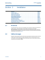
Contents
1Section 1: Introduction
1.1 Using this manual. . . . . . . . . . . . . . . . . . . . . . . . . . . . . . . . . . . . . . . . . . . . . . . . . . . . . . . 1
1.2 Service support. . . . . . . . . . . . . . . . . . . . . . . . . . . . . . . . . . . . . . . . . . . . . . . . . . . . . . . . . 1
1.3 Models covered . . . . . . . . . . . . . . . . . . . . . . . . . . . . . . . . . . . . . . . . . . . . . . . . . . . . . . . . 2
1.4 Transmitter overview . . . . . . . . . . . . . . . . . . . . . . . . . . . . . . . . . . . . . . . . . . . . . . . . . . . 3
1.5 Product recycling/ disposal . . . . . . . . . . . . . . . . . . . . . . . . . . . . . . . . . . . . . . . . . . . . . . 4
2Section 2: Installation
2.1 Overview . . . . . . . . . . . . . . . . . . . . . . . . . . . . . . . . . . . . . . . . . . . . . . . . . . . . . . . . . . . . . . 5
2.2 Safety messages . . . . . . . . . . . . . . . . . . . . . . . . . . . . . . . . . . . . . . . . . . . . . . . . . . . . . . . . 5
2.3 General considerations . . . . . . . . . . . . . . . . . . . . . . . . . . . . . . . . . . . . . . . . . . . . . . . . . . 6
2.4 Mechanical considerations . . . . . . . . . . . . . . . . . . . . . . . . . . . . . . . . . . . . . . . . . . . . . . . 7
2.5 Draft range considerations. . . . . . . . . . . . . . . . . . . . . . . . . . . . . . . . . . . . . . . . . . . . . . . 7
2.6 Environmental considerations . . . . . . . . . . . . . . . . . . . . . . . . . . . . . . . . . . . . . . . . . . . . 8
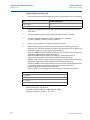
2.7 HART installation flowchart . . . . . . . . . . . . . . . . . . . . . . . . . . . . . . . . . . . . . . . . . . . . . . 9
2.8 Installation procedures . . . . . . . . . . . . . . . . . . . . . . . . . . . . . . . . . . . . . . . . . . . . . . . . .10
2.8.1 Mount the transmitter . . . . . . . . . . . . . . . . . . . . . . . . . . . . . . . . . . . . . . . . . . . .10
2.8.2 Impulse piping. . . . . . . . . . . . . . . . . . . . . . . . . . . . . . . . . . . . . . . . . . . . . . . . . . .14
2.8.3 Process connections. . . . . . . . . . . . . . . . . . . . . . . . . . . . . . . . . . . . . . . . . . . . . .16
2.8.4 Inline process connection . . . . . . . . . . . . . . . . . . . . . . . . . . . . . . . . . . . . . . . . .18
2.8.5 Housing rotation. . . . . . . . . . . . . . . . . . . . . . . . . . . . . . . . . . . . . . . . . . . . . . . . .18
2.8.6 LCD display. . . . . . . . . . . . . . . . . . . . . . . . . . . . . . . . . . . . . . . . . . . . . . . . . . . . . .19
2.8.7 Configure security and alarm . . . . . . . . . . . . . . . . . . . . . . . . . . . . . . . . . . . . . .20
2.9 Electrical considerations . . . . . . . . . . . . . . . . . . . . . . . . . . . . . . . . . . . . . . . . . . . . . . . .22
2.9.1 Conduit installation . . . . . . . . . . . . . . . . . . . . . . . . . . . . . . . . . . . . . . . . . . . . . .22
2.9.2 Wiring . . . . . . . . . . . . . . . . . . . . . . . . . . . . . . . . . . . . . . . . . . . . . . . . . . . . . . . . . .23
2.9.3 Transient protection terminal block . . . . . . . . . . . . . . . . . . . . . . . . . . . . . . . .26
2.9.4 Grounding . . . . . . . . . . . . . . . . . . . . . . . . . . . . . . . . . . . . . . . . . . . . . . . . . . . . . .27
2.10Hazardous locations certifications . . . . . . . . . . . . . . . . . . . . . . . . . . . . . . . . . . . . . . .29
2.11Rosemount 305, 306, and 304 manifolds. . . . . . . . . . . . . . . . . . . . . . . . . . . . . . . . .29
2.11.1Rosemount 305 integral manifold installation procedure . . . . . . . . . . . . .31
2.11.2Rosemount 306 integral manifold installation procedure . . . . . . . . . . . . .31
2.11.3Rosemount 304 conventional manifold installation procedure . . . . . . . .31
2.11.4Manifold operation. . . . . . . . . . . . . . . . . . . . . . . . . . . . . . . . . . . . . . . . . . . . . . .31
Table of Contents
v
Reference Manual
Table of Contents
00809-0100-4001, Rev JA
November 2012
2.12Liquid level measurement . . . . . . . . . . . . . . . . . . . . . . . . . . . . . . . . . . . . . . . . . . . . . .34
2.12.1Open vessels . . . . . . . . . . . . . . . . . . . . . . . . . . . . . . . . . . . . . . . . . . . . . . . . . . . .35
2.12.2Closed vessels . . . . . . . . . . . . . . . . . . . . . . . . . . . . . . . . . . . . . . . . . . . . . . . . . . .35
3Section 3: Configuration
3.1 Overview . . . . . . . . . . . . . . . . . . . . . . . . . . . . . . . . . . . . . . . . . . . . . . . . . . . . . . . . . . . . .39
3.2 Safety messages . . . . . . . . . . . . . . . . . . . . . . . . . . . . . . . . . . . . . . . . . . . . . . . . . . . . . . .39
3.3 Commissioning. . . . . . . . . . . . . . . . . . . . . . . . . . . . . . . . . . . . . . . . . . . . . . . . . . . . . . . .40
3.3.1 Setting the loop to manual . . . . . . . . . . . . . . . . . . . . . . . . . . . . . . . . . . . . . . . .40
3.3.2 Wiring diagrams . . . . . . . . . . . . . . . . . . . . . . . . . . . . . . . . . . . . . . . . . . . . . . . . .41
3.4 Configuration data review . . . . . . . . . . . . . . . . . . . . . . . . . . . . . . . . . . . . . . . . . . . . . .42
3.5 Field communicator. . . . . . . . . . . . . . . . . . . . . . . . . . . . . . . . . . . . . . . . . . . . . . . . . . . .42
3.5.1 Field communicator user interface . . . . . . . . . . . . . . . . . . . . . . . . . . . . . . . . .43
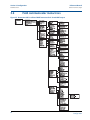
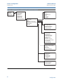
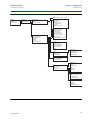
3.6 Field communicator menu trees . . . . . . . . . . . . . . . . . . . . . . . . . . . . . . . . . . . . . . . . .44
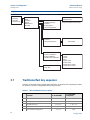
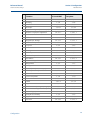
3.7 Traditional fast key sequence . . . . . . . . . . . . . . . . . . . . . . . . . . . . . . . . . . . . . . . . . . .48
3.8 Check output . . . . . . . . . . . . . . . . . . . . . . . . . . . . . . . . . . . . . . . . . . . . . . . . . . . . . . . . .50
3.8.1 Process variables . . . . . . . . . . . . . . . . . . . . . . . . . . . . . . . . . . . . . . . . . . . . . . . . .51
3.8.2 Sensor temperature . . . . . . . . . . . . . . . . . . . . . . . . . . . . . . . . . . . . . . . . . . . . . .51
3.9 Basic setup. . . . . . . . . . . . . . . . . . . . . . . . . . . . . . . . . . . . . . . . . . . . . . . . . . . . . . . . . . . .52
3.9.1 Set process variable units . . . . . . . . . . . . . . . . . . . . . . . . . . . . . . . . . . . . . . . . .52
3.9.2 Set output (Transfer function) . . . . . . . . . . . . . . . . . . . . . . . . . . . . . . . . . . . . .52
3.9.3 Rerange . . . . . . . . . . . . . . . . . . . . . . . . . . . . . . . . . . . . . . . . . . . . . . . . . . . . . . . .53
3.9.4 Damping. . . . . . . . . . . . . . . . . . . . . . . . . . . . . . . . . . . . . . . . . . . . . . . . . . . . . . . .57
3.10LCD display . . . . . . . . . . . . . . . . . . . . . . . . . . . . . . . . . . . . . . . . . . . . . . . . . . . . . . . . . . .58
3.10.1LCD display configuration for 4-20 mA HART only . . . . . . . . . . . . . . . . . . . .59
3.10.2Custom display configuration 4-20 mA HART only . . . . . . . . . . . . . . . . . . .59
3.11Detailed setup . . . . . . . . . . . . . . . . . . . . . . . . . . . . . . . . . . . . . . . . . . . . . . . . . . . . . . . .61
3.11.1Failure mode alarm and saturation . . . . . . . . . . . . . . . . . . . . . . . . . . . . . . . . .61
3.11.2Alarm and saturation levels for burst mode. . . . . . . . . . . . . . . . . . . . . . . . . .62
3.11.3Alarm and saturation values for multidrop mode. . . . . . . . . . . . . . . . . . . . .62
3.11.4Alarm level verification . . . . . . . . . . . . . . . . . . . . . . . . . . . . . . . . . . . . . . . . . . .62
3.12Diagnostics and service . . . . . . . . . . . . . . . . . . . . . . . . . . . . . . . . . . . . . . . . . . . . . . . .62
3.12.1Loop test . . . . . . . . . . . . . . . . . . . . . . . . . . . . . . . . . . . . . . . . . . . . . . . . . . . . . . .62
3.13Advanced functions . . . . . . . . . . . . . . . . . . . . . . . . . . . . . . . . . . . . . . . . . . . . . . . . . . .64
3.13.1Saving, recalling, and cloning configuration data . . . . . . . . . . . . . . . . . . . .64
3.13.2Burst mode . . . . . . . . . . . . . . . . . . . . . . . . . . . . . . . . . . . . . . . . . . . . . . . . . . . . .67
3.14Multidrop communication . . . . . . . . . . . . . . . . . . . . . . . . . . . . . . . . . . . . . . . . . . . . .68
vi
Table of Contents
Reference Manual
Table of Contents
00809-0100-4001, Rev JA
November 2012
3.15Changing a transmitter address . . . . . . . . . . . . . . . . . . . . . . . . . . . . . . . . . . . . . . . . .69
3.15.1Communicating with a multidropped transmitter. . . . . . . . . . . . . . . . . . . .69
3.15.2Polling a multidropped transmitter . . . . . . . . . . . . . . . . . . . . . . . . . . . . . . . .69
4Section 4: Operation and maintenance
4.1 Overview . . . . . . . . . . . . . . . . . . . . . . . . . . . . . . . . . . . . . . . . . . . . . . . . . . . . . . . . . . . . .71
4.2 Safety messages . . . . . . . . . . . . . . . . . . . . . . . . . . . . . . . . . . . . . . . . . . . . . . . . . . . . . . .71
4.2.1 Warnings . . . . . . . . . . . . . . . . . . . . . . . . . . . . . . . . . . . . . . . . . . . . . . . . . . . . . . .72
4.3 Calibration overview . . . . . . . . . . . . . . . . . . . . . . . . . . . . . . . . . . . . . . . . . . . . . . . . . . .72
4.3.1 Determining calibration frequency . . . . . . . . . . . . . . . . . . . . . . . . . . . . . . . . .74
4.3.2 Choosing a trim procedure . . . . . . . . . . . . . . . . . . . . . . . . . . . . . . . . . . . . . . . .76
4.4 Analog output trim . . . . . . . . . . . . . . . . . . . . . . . . . . . . . . . . . . . . . . . . . . . . . . . . . . . .77
4.4.1 Digital-to-Analog trim . . . . . . . . . . . . . . . . . . . . . . . . . . . . . . . . . . . . . . . . . . . .77
4.4.2 Digital-to-Analog trim using other scale . . . . . . . . . . . . . . . . . . . . . . . . . . . .79
4.4.3 Recall factory trim—analog output . . . . . . . . . . . . . . . . . . . . . . . . . . . . . . . . .80
4.5 Sensor trim . . . . . . . . . . . . . . . . . . . . . . . . . . . . . . . . . . . . . . . . . . . . . . . . . . . . . . . . . . .81
4.5.1 Sensor trim overview . . . . . . . . . . . . . . . . . . . . . . . . . . . . . . . . . . . . . . . . . . . . .81
4.5.2 Zero trim. . . . . . . . . . . . . . . . . . . . . . . . . . . . . . . . . . . . . . . . . . . . . . . . . . . . . . . .82
4.5.3 Sensor trim. . . . . . . . . . . . . . . . . . . . . . . . . . . . . . . . . . . . . . . . . . . . . . . . . . . . . .83
4.5.4 Recall factory trim—sensor trim . . . . . . . . . . . . . . . . . . . . . . . . . . . . . . . . . . . .84
4.5.5 Line pressure effect (range 2 and range 3). . . . . . . . . . . . . . . . . . . . . . . . . . .84
4.5.6 Compensating for line pressure . . . . . . . . . . . . . . . . . . . . . . . . . . . . . . . . . . . .85
5Section 5: Troubleshooting
5.1 Overview . . . . . . . . . . . . . . . . . . . . . . . . . . . . . . . . . . . . . . . . . . . . . . . . . . . . . . . . . . . . .89
5.2 Safety messages . . . . . . . . . . . . . . . . . . . . . . . . . . . . . . . . . . . . . . . . . . . . . . . . . . . . . . .89
5.2.1 Warnings (). . . . . . . . . . . . . . . . . . . . . . . . . . . . . . . . . . . . . . . . . . . . . . . . . . . . . .90
5.3 Diagnostic messages. . . . . . . . . . . . . . . . . . . . . . . . . . . . . . . . . . . . . . . . . . . . . . . . . . .92
5.4 Disassembly procedures . . . . . . . . . . . . . . . . . . . . . . . . . . . . . . . . . . . . . . . . . . . . . . . .97
5.4.1 Remove from service . . . . . . . . . . . . . . . . . . . . . . . . . . . . . . . . . . . . . . . . . . . . .98
5.4.2 Remove terminal block . . . . . . . . . . . . . . . . . . . . . . . . . . . . . . . . . . . . . . . . . . .99
5.4.3 Remove the electronics board . . . . . . . . . . . . . . . . . . . . . . . . . . . . . . . . . . . . .99
5.4.4 Remove the sensor module from the electronics housing . . . . . . . . . . . . .99
5.5 Reassembly procedures . . . . . . . . . . . . . . . . . . . . . . . . . . . . . . . . . . . . . . . . . . . . . . 100
5.5.1 Attach the electronics board . . . . . . . . . . . . . . . . . . . . . . . . . . . . . . . . . . . . 100
5.5.2 Install the terminal block . . . . . . . . . . . . . . . . . . . . . . . . . . . . . . . . . . . . . . . . 101
5.5.3 Reassemble the 3051C process flange . . . . . . . . . . . . . . . . . . . . . . . . . . . . 101
Table of Contents
vii
Reference Manual
Table of Contents
00809-0100-4001, Rev JA
November 2012
5.5.4 Install the drain/vent valve . . . . . . . . . . . . . . . . . . . . . . . . . . . . . . . . . . . . . . 102
AAppendix A: Specifications and reference data
A.1 Performance specifications . . . . . . . . . . . . . . . . . . . . . . . . . . . . . . . . . . . . . . . . . . . 103
A.1.1 Conformance to specification (±3s (Sigma)) . . . . . . . . . . . . . . . . . . . . . . . 103
A.1.2 Reference accuracy(1) . . . . . . . . . . . . . . . . . . . . . . . . . . . . . . . . . . . . . . . . . . 104
A.1.3 Total performance . . . . . . . . . . . . . . . . . . . . . . . . . . . . . . . . . . . . . . . . . . . . . 104
A.1.4 Long term stability . . . . . . . . . . . . . . . . . . . . . . . . . . . . . . . . . . . . . . . . . . . . . 105
A.1.5 Dynamic performance . . . . . . . . . . . . . . . . . . . . . . . . . . . . . . . . . . . . . . . . . . 105
A.1.6 Line pressure effect per 1000 psi (6,9 MPa)(1) . . . . . . . . . . . . . . . . . . . . . . 105
A.1.7 Ambient temperature effect per 50 °F (28 °C). . . . . . . . . . . . . . . . . . . . . . 106
A.1.8 Mounting position effects . . . . . . . . . . . . . . . . . . . . . . . . . . . . . . . . . . . . . . . 106
A.1.9 Vibration effect . . . . . . . . . . . . . . . . . . . . . . . . . . . . . . . . . . . . . . . . . . . . . . . . 106
A.1.10Power supply effect . . . . . . . . . . . . . . . . . . . . . . . . . . . . . . . . . . . . . . . . . . . . 107
A.1.11Electromagnetic compatibility (EMC) . . . . . . . . . . . . . . . . . . . . . . . . . . . . 107
A.1.12Transient protection (option code T1) . . . . . . . . . . . . . . . . . . . . . . . . . . . . 107
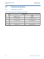
A.2 Functional specifications . . . . . . . . . . . . . . . . . . . . . . . . . . . . . . . . . . . . . . . . . . . . . 108
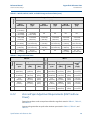
A.2.1 Range and sensor limits. . . . . . . . . . . . . . . . . . . . . . . . . . . . . . . . . . . . . . . . . 108
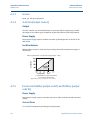
A.2.2 Zero and Span Adjustment Requirements (HART and Low Power) . . . . 109
A.2.3 Service. . . . . . . . . . . . . . . . . . . . . . . . . . . . . . . . . . . . . . . . . . . . . . . . . . . . . . . . 110
A.2.4 4–20 mA (Output Code A) . . . . . . . . . . . . . . . . . . . . . . . . . . . . . . . . . . . . . . 110
A.2.5 Foundation fieldbus (output code F) and Profibus (output code W). . . 110
A.2.6 Foundation fieldbus function block execution times . . . . . . . . . . . . . . . . 111
A.2.7 Foundation fieldbus Parameters . . . . . . . . . . . . . . . . . . . . . . . . . . . . . . . . . 111
A.2.8 Standard Function Blocks . . . . . . . . . . . . . . . . . . . . . . . . . . . . . . . . . . . . . . . 111
A.2.9 Backup Link Active Scheduler (LAS). . . . . . . . . . . . . . . . . . . . . . . . . . . . . . . 112
A.2.10Advanced control function block suite (Option Code A01) . . . . . . . . . . 112
A.2.11Foundation fieldbus Diagnostics Suite (Option Code D01) . . . . . . . . . . 112
A.2.12Low Power (output code M) . . . . . . . . . . . . . . . . . . . . . . . . . . . . . . . . . . . . . 112
A.2.13Static Pressure Limit . . . . . . . . . . . . . . . . . . . . . . . . . . . . . . . . . . . . . . . . . . . 114
A.2.14Burst Pressure Limits . . . . . . . . . . . . . . . . . . . . . . . . . . . . . . . . . . . . . . . . . . . 114
A.2.15Failure Mode Alarm . . . . . . . . . . . . . . . . . . . . . . . . . . . . . . . . . . . . . . . . . . . . 114
A.2.16Temperature Limits . . . . . . . . . . . . . . . . . . . . . . . . . . . . . . . . . . . . . . . . . . . . 115
A.3 Physical specifications . . . . . . . . . . . . . . . . . . . . . . . . . . . . . . . . . . . . . . . . . . . . . . . . 116
A.3.1 Electrical Connections . . . . . . . . . . . . . . . . . . . . . . . . . . . . . . . . . . . . . . . . . . 116
A.3.2 Process Connections . . . . . . . . . . . . . . . . . . . . . . . . . . . . . . . . . . . . . . . . . . . 116
A.3.3 Process-Wetted Parts. . . . . . . . . . . . . . . . . . . . . . . . . . . . . . . . . . . . . . . . . . . 117
viii
Table of Contents
Reference Manual
Table of Contents
00809-0100-4001, Rev JA
November 2012
A.3.4 Rosemount 3051L Process Wetted Parts . . . . . . . . . . . . . . . . . . . . . . . . . . 118
A.3.5 Non-Wetted Parts. . . . . . . . . . . . . . . . . . . . . . . . . . . . . . . . . . . . . . . . . . . . . . 118
A.3.6 Shipping Weights . . . . . . . . . . . . . . . . . . . . . . . . . . . . . . . . . . . . . . . . . . . . . . 119
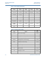
A.4 Dimensional Drawings . . . . . . . . . . . . . . . . . . . . . . . . . . . . . . . . . . . . . . . . . . . . . . . 120
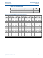
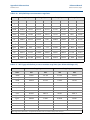
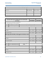
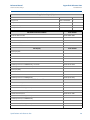
A.5 Ordering Information . . . . . . . . . . . . . . . . . . . . . . . . . . . . . . . . . . . . . . . . . . . . . . . . 131
A.5.1 Options (Include with selected model number) . . . . . . . . . . . . . . . . . . . . 133
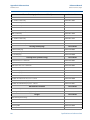
A.5.2 Options (Include with selected model number) . . . . . . . . . . . . . . . . . . . . 140
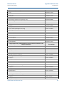
A.5.3 Options (Include with selected model number) . . . . . . . . . . . . . . . . . . . . 147
A.5.4 Options (Include with selected model number) . . . . . . . . . . . . . . . . . . . . 152
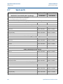
A.6 Options . . . . . . . . . . . . . . . . . . . . . . . . . . . . . . . . . . . . . . . . . . . . . . . . . . . . . . . . . . . . 156
A.7 Spare parts. . . . . . . . . . . . . . . . . . . . . . . . . . . . . . . . . . . . . . . . . . . . . . . . . . . . . . . . . . 164
BAppendix B: Product certifications
B.1 Overview . . . . . . . . . . . . . . . . . . . . . . . . . . . . . . . . . . . . . . . . . . . . . . . . . . . . . . . . . . . 175
B.2 Safety messages . . . . . . . . . . . . . . . . . . . . . . . . . . . . . . . . . . . . . . . . . . . . . . . . . . . . . 175
B.2.1 Warnings . . . . . . . . . . . . . . . . . . . . . . . . . . . . . . . . . . . . . . . . . . . . . . . . . . . . . 176
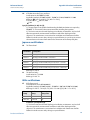
B.3 Approved manufacturing locations . . . . . . . . . . . . . . . . . . . . . . . . . . . . . . . . . . . . 176
B.4 European directive information. . . . . . . . . . . . . . . . . . . . . . . . . . . . . . . . . . . . . . . . 176
B.4.1 Ordinary location certification for factory mutual . . . . . . . . . . . . . . . . . . 176
B.5 Hazardous locations certifications . . . . . . . . . . . . . . . . . . . . . . . . . . . . . . . . . . . . . 177
B.5.1 North american certifications. . . . . . . . . . . . . . . . . . . . . . . . . . . . . . . . . . . . 177
B.6 Approval drawings . . . . . . . . . . . . . . . . . . . . . . . . . . . . . . . . . . . . . . . . . . . . . . . . . . . 184
B.6.1 Factory mutual 03031-1019. . . . . . . . . . . . . . . . . . . . . . . . . . . . . . . . . . . . . 184
B.6.2 Canadian standards association (CSA) 03031-1024 . . . . . . . . . . . . . . . . 197
Table of Contents
ix
Table of Contents
November 2012
x
Reference Manual
00809-0100-4001, Rev JA
Table of Contents
Section 1: Introduction
Reference Manual
November 2012
00809-0100-4001, Rev JA
Section 1
1.1
Introduction
Using this manual
The sections in this manual provide information on installing, operating, and maintaining the
Rosemount 3051. The sections are organized as follows:
Section 2: Installation contains mechanical and electrical installation instructions, and field
upgrade options.
Section 3: Configuration provides instruction on commissioning and operating Rosemount
3051 transmitters. Information on software functions, configuration parameters, and online
variables is also included.
Section 4: Operation and maintenance contains operation and maintenance techniques.
Section 5: Troubleshooting provides troubleshooting techniques for the most common
operating problems.
Appendix A: Specifications and reference data supplies reference and specification data, as well
as ordering information.
Appendix B: Product certifications contains intrinsic safety approval information, European
ATEX directive information, and approval drawings.
1.2
Service support
To expedite the return process outside of the United States, contact the nearest Emerson
Process Management representative.
Within the United States, call the Emerson Process Management Instrument and Valve
Response Center using the 1-800-654-RSMT (7768) toll-free number. This center, available 24
hours a day, will assist you with any needed information or materials.
The center will ask for product model and serial numbers, and will provide a Return Material
Authorization (RMA) number. The center will also ask for the process material to which the
product was last exposed.
Introduction
1
Reference Manual
Section 1: Introduction
00809-0100-4001, Rev JA
November 2012
Individuals who handle products exposed to a hazardous substance can avoid injury if they
are informed of and understand the hazard. The product being returned will require a copy
of the required Material Safety Data Sheet (MSDS) for each substance must be included
with the returned goods.
Emerson Process Management Instrument and Valve Response Center representatives will
explain the additional information and procedures necessary to return goods exposed to
hazardous substances.
1.3
Models covered
The following Rosemount 3051 Pressure Transmitters are covered by this manual:
Rosemount 3051C coplanar pressure transmitter
Rosemount 3051CD Differential Pressure Transmitter
Measures differential pressure up to 2000 psi (137,9 bar).
Rosemount 3051CG Gage Pressure Transmitter
Measures gage pressure up to 2000 psi (137,9 bar).
Rosemount 3051CA Absolute Pressure Transmitter
Measures absolute pressure up to 4000 psia (275,8 bar).
Rosemount 3051T in-line pressure transmitter
Rosemount 3051T Gage and Absolute Pressure Transmitter
Measures gage pressure up to 10000 psi (689,5 bar).
Rosemount 3051L liquid level transmitter
Provides precise level and specific gravity measurements up to 300 psi (20,7 bar) for a wide
variety of tank configurations.
Rosemount 3051H high process temperature pressure
transmitter
Provides high process temperature capability to 375 °F (191 °C) for measuring differential or
gage pressure without use of remote diaphragm seals or capillaries.
2
Introduction
Reference Manual
Section 1: Introduction
00809-0100-4001, Rev JA
November 2012
Note
For Rosemount 3051 with FOUNDATION™ fieldbus, see Rosemount Product Manual
00809-0100-4774. For Rosemount 3051 with Profibus PA, see Rosemount Product Manual
00809-0100-4797.
1.4
Transmitter overview
The Rosemount 3051C Coplanar™ design is offered for Differential Pressure (DP), Gage Pressure
(GP) and Absolute Pressure (AP) measurements. The Rosemount 3051C utilizes Emerson
Process Management capacitance sensor technology for DP and GP measurements.
Piezoresistive sensor technology is utilized in the Rosemount 3051T and 3051CA
measurements.
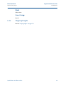
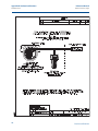
The major components of the Rosemount 3051 are the sensor module and the electronics
housing. The sensor module contains the oil filled sensor system (isolating diaphragms, oil fill
system, and sensor) and the sensor electronics. The sensor electronics are installed within the
sensor module and include a temperature sensor (RTD), a memory module, and the
capacitance to digital signal converter (C/D converter). The electrical signals from the sensor
module are transmitted to the output electronics in the electronics housing. The electronics
housing contains the output electronics board, the local zero and span buttons, and the
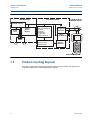
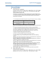
terminal block. The basic block diagram of the Rosemount 3051CD is illustrated in Figure 1-1.
For the Rosemount 3051C design pressure is applied to the isolating diaphragms, the oil
deflects the center diaphragm, which then changes the capacitance. This capacitance signal is
then changed to a digital signal in the C/D converter. The microprocessor then takes the signals
from the RTD and C/D converter calculates the correct output of the transmitter. This signal is
then sent to the D/A converter, which converts the signal back to an analog signal and
superimposes the HART signal on the 4-20 mA output.
Introduction
3
Reference Manual
Section 1: Introduction
00809-0100-4001, Rev JA
November 2012
Figure 1-1. Block diagram of operation
SENSOR MODULE
4—20 MA SIGNAL TO
CONTROL SYSTEM
ELECTRONICS BOARD
Signal Processing
Microcomputer
Temp.
Sensor
Sensor
Module
Memory
Sensor linearization
Rerange
Damping
Diagnostics
Engineering
Communication
Module Memory
Rerange values
Configuration
Digital-toAnalog Signal
Conversion
Digital
Communication
Local Span
and Zero
Adjustment
FIELD COMMUNICATOR
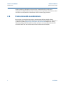
1.5
Product recycling/ disposal
Recycling of equipment and packaging should be taken into consideration and disposed of in
accordance with local and national legislation/regulations.
4
Introduction
Section 2: Installation
Reference Manual
November 2012
00809-0100-4001, Rev JA
Section 2
Installation
Overview . . . . . . . . . . . . . . . . . . . . . . . . . . . . . . . . . . . . . . . . . . . . . . . . . . . . . . . . . . . . . . . page 5
Safety messages . . . . . . . . . . . . . . . . . . . . . . . . . . . . . . . . . . . . . . . . . . . . . . . . . . . . . . . . . page 5
General considerations . . . . . . . . . . . . . . . . . . . . . . . . . . . . . . . . . . . . . . . . . . . . . . . . . . . page 6
Mechanical considerations . . . . . . . . . . . . . . . . . . . . . . . . . . . . . . . . . . . . . . . . . . . . . . . . page 7
Draft range considerations . . . . . . . . . . . . . . . . . . . . . . . . . . . . . . . . . . . . . . . . . . . . . . . page 7
Environmental considerations . . . . . . . . . . . . . . . . . . . . . . . . . . . . . . . . . . . . . . . . . . . . page 8
HART installation flowchart . . . . . . . . . . . . . . . . . . . . . . . . . . . . . . . . . . . . . . . . . . . . . . . page 9
Installation procedures . . . . . . . . . . . . . . . . . . . . . . . . . . . . . . . . . . . . . . . . . . . . . . . . . . . page 10
Electrical considerations . . . . . . . . . . . . . . . . . . . . . . . . . . . . . . . . . . . . . . . . . . . . . . . . . . page 22
Hazardous locations certifications . . . . . . . . . . . . . . . . . . . . . . . . . . . . . . . . . . . . . . . . . page 29
Rosemount 305, 306, and 304 manifolds . . . . . . . . . . . . . . . . . . . . . . . . . . . . . . . . . . . page 29
Liquid level measurement . . . . . . . . . . . . . . . . . . . . . . . . . . . . . . . . . . . . . . . . . . . . . . . . page 34
2.1
Overview
The information in this section covers installation considerations for the Rosemount 3051 with
HART protocols. A Quick Installation Guide for HART protocol (document number
00825-0100-4001) is shipped with every transmitter to describe basic pipe-fitting and wiring
procedures for initial installation. Dimensional drawings for each 3051 variation and mounting
configuration are included on page 13.
2.2
Safety messages
Procedures and instructions in this section may require special precautions to ensure the safety
of the personnel performing the operation. Information that raises potential safety issues is
indicated by a warning symbol ( ). Refer to the following safety messages before performing
an operation preceded by this symbol.
Installation
5
Reference Manual
Section 2: Installation
00809-0100-4001, Rev JA
November 2012
Explosions could result in death or serious injury:
Installation of this transmitter in an explosive environment must be in accordance with the
appropriate local, national, and international standards, codes, and practices. Please review
the approvals section of the 3051 reference manual for any restrictions associated with a
safe installation.
Before connecting a Field Communicator in an explosive atmosphere, ensure the
instruments in the loop are installed in accordance with intrinsically safe or
non-incendive field wiring practices.
In an Explosion-Proof/Flameproof installation, do not remove the transmitter covers
when power is applied to the unit.
Process leaks may cause harm or result in death.
Install and tighten process connectors before applying pressure.
Electrical shock can result in death or serious injury.
Avoid contact with the leads and terminals. High voltage that may be present on leads
can cause electrical shock.
Electrical shock can result in death or serious injury.
Avoid contact with the leads and terminals.
Process leaks could result in death or serious injury.
Install and tighten all four flange bolts before applying pressure.
Do not attempt to loosen or remove flange bolts while the transmitter is in service.
Replacement equipment or spare parts not approved by Emerson Process Management for
use as spare parts could reduce the pressure retaining capabilities of the transmitter and
may render the instrument dangerous.
Use only bolts supplied or sold by Emerson Process Management as spare parts.
Refer to page 164 for a complete list of spare parts.
Improper assembly of manifolds to traditional flange can damage sensor module.
2.3
For safe assembly of manifold to traditional flange, bolts must break back plane of
flange web (i.e., bolt hole) but must not contact sensor module housing.
General considerations
Measurement accuracy depends upon proper installation of the transmitter and impulse piping.
Mount the transmitter close to the process and use a minimum of piping to achieve best
accuracy. Keep in mind the need for easy access, personnel safety, practical field calibration, and
a suitable transmitter environment. Install the transmitter to minimize vibration, shock, and
temperature fluctuation.
6
Installation
Reference Manual
Section 2: Installation
00809-0100-4001, Rev JA
November 2012
Important
Install the enclosed pipe plug (found in the box) in unused conduit opening with a minimum of
five threads engaged to comply with explosion-proof requirements.
For material compatibility considerations, see document number 00816-0100-3045 on
www.emersonprocess.com/rosemount.
2.4
Mechanical considerations
Note
For steam service or for applications with process temperatures greater than the limits of the
transmitter, do not blow down impulse piping through the transmitter. Flush lines with the
blocking valves closed and refill lines with water before resuming measurement.
Note
When the transmitter is mounted on its side, position the Coplanar flange to ensure proper
venting or draining. Mount the flange as shown in Figure 2-8 on page 16, keeping drain/vent
connections on the bottom for gas service and on the top for liquid service.
2.5
Draft range considerations
Installation
For the Rosemount 3051CD0 draft range pressure transmitter, it is best to mount the
transmitter with the isolators parallel to the ground. Installing the transmitter in this way
reduces oil head effect and provides for optimal temperature performance.
Be sure the transmitter is securely mounted. Tilting of the transmitter may cause a zero shift in
the transmitter output.
Reducing process noise
There are two recommended methods of reducing process noise: output damping and, in gage
applications, reference side filtering.
Output damping
The output damping for the Rosemount 3051CD0 is factory set to 3.2 seconds as a default. If
the transmitter output is still noisy, increase the damping time. If faster response is needed,
decrease the damping time. Damping adjustment information is available on page 57.
Reference side filtering
In gage applications it is important to minimize fluctuations in atmospheric pressure to which
the low side isolator is exposed.
One method of reducing fluctuations in atmospheric pressure is to attach a length of tubing to
the reference side of the transmitter to act as a pressure buffer.
Installation
7
Section 2: Installation
Reference Manual
00809-0100-4001, Rev JA
November 2012
Another method is to plumb the reference side to a chamber that has a small vent to
atmosphere. If multiple draft transmitters are being used in an application, the reference side of
each device can be plumbed to a chamber to achieve a common gage reference.
2.6
Environmental considerations
Best practice is to mount the transmitter in an environment that has minimal ambient
temperature change. The transmitter electronics temperature operating limits are –40 to 185 °F
(–40 to 85 °C). Refer to Appendix A: Specifications and reference data that lists the sensing
element operating limits. Mount the transmitter so that it is not susceptible to vibration and
mechanical shock and does not have external contact with corrosive materials.
8
Installation
Reference Manual
Section 2: Installation
00809-0100-4001, Rev JA
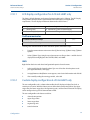
2.7
November 2012
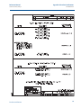
HART installation flowchart
Figure 2-1. HART installation flowchart
START HERE
Bench
Calibration?
No
Field Install
Yes
Configure
Set Units
(page 52)
Set Range
Points
(page 53)
Configure Security
and Alarm
(page 20)
Verify
Mount
Transmitter
(page 10)
Review
Transmitter
Configuration
(page 42)
Wire Transmitter
(pages 23–31)
Apply Pressure
Power
Transmitter
(page 25)
Set Output Type
(page 52)
Within
Specifications?
Set Damping
(page 57)
Yes
Check Process
Connection
(page 16)
No
Refer to
Section 4:
Operation and
maintenance
Confirm
Transmitter
Configuration
(page 42)
Trim Transmitter
for Mounting
Effects
(page 76)
Done
Installation
9
Section 2: Installation
Reference Manual
00809-0100-4001, Rev JA
November 2012
2.8
Installation procedures
2.8.1
Mount the transmitter
For dimensional drawing information refer to Appendix A: Specifications and reference data on
page 120.
Process flange orientation
Mount the process flanges with sufficient clearance for process connections. For safety reasons,
place the drain/vent valves so the process fluid is directed away from possible human contact
when the vents are used. In addition, consider the need for a testing or calibration input.
Note
Most transmitters are calibrated in the horizontal position. Mounting the transmitter in any
other position will shift the zero point to the equivalent amount of liquid head pressure caused
by the varied mounting position. To reset zero point, refer to “Sensor Trim” on page 10.
Housing rotation
See “Housing rotation” on page 18.
Terminal side of electronics housing
Mount the transmitter so the terminal side is accessible. Clearance of 0.75 in. (19 mm) is
required for cover removal. Use a conduit plug in the unused conduit opening.
Circuit side of electronics housing
Provide 0.75 in. (19 mm) of clearance for units with out an LCD display. Three inches of
clearance is required for cover removal if a meter is installed.
Cover installation
Always ensure a proper seal by installing the electronics housing cover(s) so that metal contacts
metal. Use Rosemount O-rings.
Conduit entry threads
For NEMA 4X, IP66, and IP68 requirements, use thread seal (PTFE) tape or paste on male threads
to provide a watertight seal.
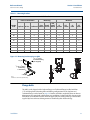
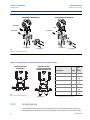
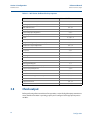
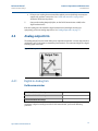
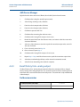
Mounting brackets
Rosemount 3051 Transmitters may be panel-mounted or pipe-mounted through an optional
mounting bracket. Refer to Table 2-1 for the complete offering and see Figure 2-2 through
Figure 2-5 on pages 11 and 12 for dimensions and mounting configurations.
10
Installation
Reference Manual
Section 2: Installation
00809-0100-4001, Rev JA
November 2012
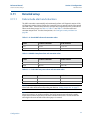
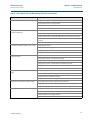
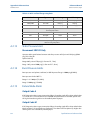
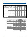
Table 2-1. Mounting brackets
3051 brackets
Process connections
Mounting
Materials
Flat
Pipe
Panel panel
Coplanar In-line Traditional mount mount mount
Option
code
B4
X
X
X
B1
X
B2
X
B3
X
B7
X
B8
X
B9
X
BA
X
BC
X
X
CS
SST
bracket bracket
X
X
X
X
X
X
X
X
X
CS
bolts
X
SST
bolts
X
X
X
X
X
X
X
X
X
X
X
X
X
X
X
X
X
Figure 2-2. Mounting bracket option code B4
/16 ⫻ 11/2 Bolts
for Panel Mounting
(Not Supplied)
5
2.8 (71)
3
/8–16 × 11/4 Bolts
for Mounting
to Transmitter
3.4 (85)
Note
Dimensions are in inches (millimeters).
Flange bolts
The 3051 can be shipped with a Coplanar flange or a Traditional flange installed with four
1.75-inch flange bolts. Mounting bolts and bolting configurations for the Coplanar and
Traditional flanges can be found on page 14. Stainless steel bolts supplied by Emerson Process
Management are coated with a lubricant to ease installation. Carbon steel bolts do not require
lubrication. No additional lubricant should be applied when installing either type of bolt. Bolts
supplied by Emerson Process Management are identified by their head markings:
Installation
11
Reference Manual
Section 2: Installation
00809-0100-4001, Rev JA
November 2012
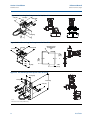
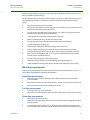
Figure 2-3. Mounti ng bracket option codes B1, B7, and BA
3.75 (95)
1.63 (41)
4.09 (104)
2.73 (69)
4.97 (126)
2.81
(71)
Figure 2-4. Panel mounting bracket option codes B2 and B8
3.75 (95)
1.63 (41)
Mounting Holes
0.375 Diameter
(10)
4.09 (104)
1.405
(35,7)
1.40
(36)
2.81
(71)
4.5 (114)
1.405
(35,7)
Figure 2-5. Flat mounting bracket option codes B3 and BC
2.125 (54)
1.625 (41)
8.00 (203)
2.81 (71)
Note
Dimensions are in inches (millimeters).
12
Installation
Reference Manual
Section 2: Installation
00809-0100-4001, Rev JA
November 2012
B7M
Carbon Steel (CS) Head Markings
Stainless Steel (SST) Head Markings
660
CL A
316
B8M
KM
Alloy K-500 Head Marking
F593_*
* The last digit in the F593_ head marking may be
any letter between A and M.
Bolt installation
Only use bolts supplied with the Rosemount 3051 or sold by Emerson Process Management as
spare parts for the Rosemount 3051 transmitter. Use the following bolt installation procedure:
1.
Finger-tighten the bolts.
2.
Torque the bolts to the initial torque value using a crossing pattern (see Table 2-2 for
torque values).
3.
Torque the bolts to the final torque value using the same
crossing pattern.
Table 2-2. Bolt installation torque values
Bolt material
Initial torque value
Final torque value
CS-ASTM-A445 Standard
300 in.-lb (34 N-m)
650 in.-lb (73 N-m)
316 SST—Option L4
150 in.-lb (17 N-m)
300 in.-lb (34 N-m)
ASTM-A-19 B7M—Option L5
300 in.-lb (34 N-m)
650 in.-lb (73 N-m)
Alloy 400—Option L6
300 in.-lb (34 N-m)
650 in.-lb (73 N-m)
See “Safety messages” on page 5 for complete warning
Installation
13
Reference Manual
Section 2: Installation
00809-0100-4001, Rev JA
November 2012
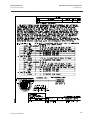
Figure 2-4. Traditional flange bolt configurations
DIFFERENTIAL TRANSMITTER
GAGE/ABSOLUTE TRANSMITTER
Drain/Vent
Plug
Drain/Vent
Drain/Vent
1.75 (44) × 4
1.75 (44) × 4
1.50 (38) × 4
1.50 (38) × 4
Note
Dimensions are in inches (millimeters).
Figure 2-7. Mounting bolts and bolt configurations for coplanar flange
TRANSMITTER WITH
FLANGE BOLTS
TRANSMITTER WITH
FLANGE ADAPTERS AND
FLANGE/ADAPTER BOLTS
Description
Qty
Size
in.
(mm)
Differential Pressure
Flange Bolts
4
1.75
(44)
Flange/Adapter Bolts
4
2.88
(73)
Flange Bolts
4
1.75
(44)
Flange/Adapter Bolts
2
2.88
(73)
Gage/Absolute Pressure (1)
1.75 (44) × 4
Note
Dimensions are in inches (millimeters).
2.88 (73) × 4
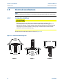
2.8.2
(1) Rosemount 3051T transmitters are direct mount and do
not require bolts for process connection.
Impulse piping
The piping between the process and the transmitter must accurately transfer the pressure to
obtain accurate measurements. There are five possible sources of error: pressure transfer, leaks,
14
Installation
Reference Manual
Section 2: Installation
00809-0100-4001, Rev JA
November 2012
friction loss (particularly if purging is used), trapped gas in a liquid line, liquid in a gas line, and
density variations between the legs.
The best location for the transmitter in relation to the process pipe is dependent on the process.
Use the following guidelines to determine transmitter location and placement of impulse
piping:
Keep impulse piping as short as possible.
For liquid service, slope the impulse piping at least 1 in./foot (8 cm/m) upward from the
transmitter toward the process connection.
For gas service, slope the impulse piping at least 1 in./foot (8 cm/m) downward from
the transmitter toward the process connection.
Avoid high points in liquid lines and low points in gas lines.
Make sure both impulse legs are the same temperature.
Use impulse piping large enough to avoid friction effects and blockage.
Vent all gas from liquid piping legs.
When using a sealing fluid, fill both piping legs to the same level.
When purging, make the purge connection close to the process taps and purge
through equal lengths of the same size pipe. Avoid purging through the transmitter.
Keep corrosive or hot (above 250 °F [121 °C]) process material out of direct contact
with the sensor module and flanges.
Prevent sediment deposits in the impulse piping.
Maintain equal leg of head pressure on both legs of the impulse piping.
Avoid conditions that might allow process fluid to freeze within the process flange.
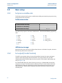
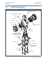
Mounting requirements
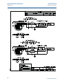
Impulse piping configurations depend on specific measurement conditions. Refer to Figure 2-8
for examples of the following mounting configurations:
Liquid flow measurement
Place taps to the side of the line to prevent sediment deposits on the transmitter’s
process isolators.
Mount the transmitter beside or below the taps so gases can vent into the process line.
Mount drain/vent valve upward to allow gases to vent.
Gas flow measurement
Place taps in the top or side of the line.
Mount the transmitter beside or above the taps so liquid will drain into the process line.
Steam flow measurement
Installation
Place taps to the side of the line.
Mount the transmitter below the taps to ensure that the impulse piping will stay filled
with condensate.
In steam service above 250 °F (121 °C), fill impulse lines with water to prevent steam
from contacting the transmitter directly and to ensure accurate measurement start-up.
15
Reference Manual
Section 2: Installation
00809-0100-4001, Rev JA
November 2012
Note
For steam or other elevated temperature services, it is important that temperatures at the
process connection do not exceed the transmitter’s process temperature limits.
Figure 2-8. Installation examples
GAS OR LIQUID SERVICE
GAS SERVICE
STEAM SERVICE
Flow
Flow
Flow
2.8.3
Process connections
Coplanar or traditional process connection
Install and tighten all four flange bolts before applying pressure, or process leakage will result.
When properly installed, the flange bolts will protrude through the top of the sensor module
housing. Do not attempt to loosen or remove the flange bolts while the transmitter is in service.
Flange adaptors:
Rosemount 3051DP and GP process connections on the transmitter flanges are 1/4–18 NPT.
Flange adapters are available with standard 1/2–14 NPT Class 2 connections. The flange adapters
allow users to disconnect from the process by removing the flange adapter bolts. Use
plant-approved lubricant or sealant when making the process connections. Refer to
Dimensional Drawings on page 120 for the distance between pressure connections. This
distance may be varied ±1/8 in. (3.2 mm) by rotating one or both of the flange adapters.
To install adapters to a Coplanar flange, perform the following procedure:
16
1.
Remove the flange bolts.
2.
Leaving the flange in place, move the adapters into position with the o-ring installed.
3.
Clamp the adapters and the Coplanar flange to the transmitter sensor module using the
larger of the bolts supplied.
4.
Tighten the bolts. Refer to “Flange bolts” on page 11 for torque specifications.
Installation
Reference Manual
Section 2: Installation
00809-0100-4001, Rev JA
November 2012
Whenever you remove flanges or adapters, visually inspect the PTFE o-rings. Replace with o-ring
designed for Rosemount transmitter if there are any signs of damage, such as nicks or cuts.
Undamaged o-rings may be reused. If you replace the o-rings, retorque the flange bolts after
installation to compensate for cold flow. Refer to the process sensor body reassembly procedure
in Section 5: Troubleshooting.
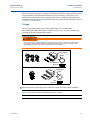
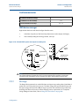
O-rings:
The two styles of Rosemount flange adapters (Rosemount 1151 and Rosemount
3051S/3051/2051/3095) each require a unique O-ring (see Figure 2-9). Use only the O-ring
designed for the corresponding flange adaptor.
Figure 2-9. O-Rings.
Failure to install proper flange adapter O-rings may cause process leaks, which can result in death or
serious injury. The two flange adapters are distinguished by unique O-ring grooves. Only use the
O-ring that is designed for its specific flange adapter, as shown below.
Rosemount 3051S / 3051 / 2051 / 3095
Flange Adapter
O-ring
PTFE Based
Elastomer
Rosemount 1151
Flange Adapter
O-ring
PTFE
Elastomer
When compressed, PTFE O-rings tend to “cold flow,” which aids in their sealing capabilities.
Note
PTFE O-rings should be replaced if the flange adapter is removed.
Installation
17
Reference Manual
Section 2: Installation
00809-0100-4001, Rev JA
November 2012
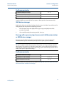
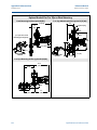
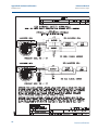
2.8.4
Inline process connection
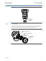
Inline gage transmitter orientation
The low side pressure port on the inline gage transmitter is located in the neck of the
transmitter, behind the housing. The vent path is 360 degrees around the transmitter between
the housing and sensor (See Figure 2-10).
Keep the vent path free of any obstruction, such as paint, dust, and lubrication by mounting the
transmitter so that the process can drain away.
Figure 2-10. Inline gage low side pressure port
Low side pressure port
(atmospheric reference)
Do not apply torque directly to the sensor module. Rotation between the sensor module
and the process connection can damage the electronics. To avoid damage, apply torque
only to the hex-shaped process connection.
Sensor Module
Process Connection
2.8.5
Housing rotation
The electronics housing can be rotated up to 180 degrees in either direction to improve field
access, or to better view the optional LCD display. To rotate the housing, perform the following
procedure:
18
1.
5
- -in. hex wrench.
Loosen the housing rotation set screw using a -----
2.
Turn the housing left or right up to 180° from its original position. Over rotating will
damage the transmitter.
3.
Retighten the housing rotation set screw.
64
Installation
Reference Manual
Section 2: Installation
00809-0100-4001, Rev JA
November 2012
Figure 2-11. Housing rotation
Housing Rotation
Set Screw
(5/64-in.)
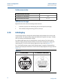
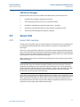
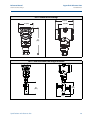
2.8.6
LCD display
Transmitters ordered with the LCD option are shipped with the display installed. Installing the
display on an existing 3051 transmitter requires a small instrument screwdriver.
Figure 2-12. LCD display
.
Interconnecting Pins
Jumpers (Top and Bottom)
LCD Display
Extended
Cover
Installation
19
Reference Manual
Section 2: Installation
00809-0100-4001, Rev JA
November 2012
2.8.7
Configure security and alarm
Security (write protect)
There are three security methods with the Rosemount 3051 transmitter:
1.
Security Jumper: prevents all writes to transmitter configuration.
2.
Local Keys (Local Zero and Span) Software Lock Out: prevents changes to transmitter
range points via local zero and span adjustment keys. With local keys security enabled,
changes to configuration are possible via HART.
3.
Physical Removal of Local Keys (Local Zero and Span) Magnetic Buttons: removes ability
to use local keys to make transmitter range point adjustments. With local keys security
enabled, changes to configuration are possible via HART.
You can prevent changes to the transmitter configuration data with the write protection
jumper. Security is controlled by the security (write protect) jumper located on the electronics
board or LCD display. Position the jumper on the transmitter circuit board in the “ON” position
to prevent accidental or deliberate change of configuration data.
If the transmitter write protection jumper is in the “ON” position, the transmitter will not accept
any “writes” to its memory. Configuration changes, such as digital trim and reranging, cannot
take place when the transmitter security is on.
Note
If the security jumper is not installed, the transmitter will continue to operate in the security OFF
configuration.
Configuring transmitter security and alarm jumper procedure
To reposition the jumpers, follow the procedure described below.
1.
Do not remove the transmitter covers in explosive atmospheres when the circuit is live.
If the transmitter is live, set the loop to manual and remove power.
2.
Remove the housing cover opposite the field terminal side. Do not remove the
transmitter covers in explosive atmospheres when the circuit is live.
3.
Reposition the jumpers as desired.
4.
20
–
Figure 2-13 shows the jumper positions for the 4-20 mA HART Transmitter.
–
Figure 2-14 shows the jumper positions for the 1-5 HART Vdc Low Power
Transmitter.
Reattach the transmitter cover. Always ensure a proper seal by installing the electronics
housing covers so that metal contacts metal to meet explosion-proof requirements.
Installation
Reference Manual
Section 2: Installation
00809-0100-4001, Rev JA
November 2012
Figure 2-13. Electronics board
4-20 mA HART
Without LCD Meter
With LCD Display
Alarm
Security
Figure 2-14. Low power transmitter electronics boards
1-5 Vdc HART Low Power
Without LCD Meter
With LCD Display
Alarm
Security
TRANSMITTER SECURITY
JUMPER POSITIONS
Write Protect ON
Write Protect OFF
Note
Security jumper not installed = Not Write Protected
Alarm jumper not installed = High Alarm
Installation
21
Reference Manual
Section 2: Installation
00809-0100-4001, Rev JA
November 2012
2.9
Electrical considerations
Note
Make sure all electrical installation is in accordance with national and local code requirements.
2.9.1
Conduit installation
If all connections are not sealed, excess moisture accumulation can damage the
transmitter. Make sure to mount the transmitter with the electrical housing positioned
downward for drainage. To avoid moisture accumulation in the housing, install wiring with
a drip loop, and ensure the bottom of the drip loop is mounted lower than the conduit
connections or the transmitter housing.
Recommended conduit connections are shown in Figure 2-15.
Figure 2-15. Conduit installation diagrams.
Possible
Conduit Line
Positions
Conduit
Lines
Sealing
Compound
Sealing
Compound
CORRECT
22
Possible
Conduit Line
Positions
CORRECT
INCORRECT
Installation
Reference Manual
Section 2: Installation
00809-0100-4001, Rev JA
2.9.2
November 2012
Wiring
Do not connect the power signal wiring to the test terminals. Voltage may burn out the
reverse-polarity protection diode in the test connection.
Note
Use shielded twisted pairs to yield best results. To ensure proper communication, use 24 AWG
or larger wire, and do not exceed 5000 feet (1500 meters).
Figure 2-16. 4-20 mA HART wiring
Power
Supply
RL 250
Installation
23
Reference Manual
Section 2: Installation
00809-0100-4001, Rev JA
November 2012
Figure 2-17. 1-5 Vdc low power wiring
Power
Supply
Voltmeter
24
Installation
Reference Manual
Section 2: Installation
00809-0100-4001, Rev JA
November 2012
Perform the following procedure to make wiring connections:
1.
Remove the housing cover on terminal compartment side. Do not remove the cover in
explosive atmospheres when the circuit is live. Signal wiring supplies all power to the
transmitter.
2.
a. For 4-20 mA HART output, connect the positive lead to the terminal marked (+) and
the negative lead to the terminal marked (pwr/comm -). Do not connect powered
signal wiring to the test terminals. Power could damage the test diode.
b. For 1-5 Vdc HART Low Power output, connect the positive lead to the terminal
marked (+ pwr) and the negative lead to the terminal marked (pwr -). Connect signal
lead to Vout / comm +.
3.
Plug and seal unused conduit connection on the transmitter housing to avoid moisture
accumulation in the terminal side. Install wiring with a drip loop. Arrange the drip loop
so the bottom is lower than the conduit connections and the transmitter housing.
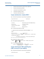
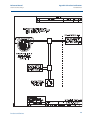
Power supply for 4-20 mA HART
Transmitter operates on 10.5 - 42.4 Vdc. The dc power supply should provide power with less
than two percent ripple.
Note
A minimum loop resistance of 250 ohms is required to communicate with a Field
Communicator. If a single power supply is used to power more than one 3051 transmitter, the
power supply used, and circuitry common to the transmitters, should not have more than
20 ohms of impedance at 1200 Hz.
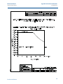
Figure 2-18. Load limitation
Maximum Loop Resistance = 43.5 * (Power Supply Voltage – 10.5)
Load (Ohms)
1387
1000
500
Operating
Region
0
10.5
20
30
Voltage (Vdc)
42.4
The Field Communicator requires a minimum loop resistance of 250 for communication.
The total resistance load is the sum of the resistance of the signal leads and the load resistance
of the controller, indicator, and related pieces. Note that the resistance of intrinsic safety
barriers, if used, must be included.
See “Safety messages” on page 5 for complete warning
Installation
25
Reference Manual
Section 2: Installation
00809-0100-4001, Rev JA
November 2012
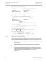
Power supply for 1-5 Vdc HART low power
Low power transmitters operate on 6-14 Vdc. The dc power supply should provide power with
less than two percent ripple. The Vout load should be 100 k or greater.
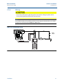
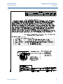
2.9.3
Transient protection terminal block
The transmitter will withstand electrical transients of the energy level usually encountered in
static discharges or induced switching transients. However, high-energy transients, such as
those induced in wiring from nearby lightning strikes, can damage the transmitter.
The transient protection terminal block can be ordered as an installed option (Option Code T1 in
the transmitter model number) or as a spare part to retrofit existing 3051 transmitters in the
field. See “Spare parts” on page 164 for spare part numbers. The lightning bolt symbol shown in
Figure 2-19 and Figure 2-20 identifies the transient protection terminal block.
Figure 2-19. 4-20 mA HART wiring with transient protection
Power
Supply
Power
Supply
RL 250
26
Installation
Reference Manual
Section 2: Installation
00809-0100-4001, Rev JA
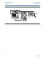
November 2012
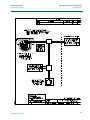
Figure 2-20. 1-5 Vdc low power wiring with transient protection
Power
Supply
Voltmeter
Figure 2-21. Wiring pair and ground
Minimize
Distance
Trim shield and
insulate
Ground for
Transient
Protection
DP
Insulate
Shield
Minimize
Distance
Connect Shield Back to the Power
Supply Ground
Note
The transient protection terminal block does not provide transient protection unless the
transmitter case is properly grounded. Use the guidelines to ground the transmitter case. Refer
to page 27.
Do not run the transient protection ground wire with signal wiring as the ground wire may carry
excessive current if a lightning strike occurs.
2.9.4
Grounding
Use the following techniques to properly ground the transmitter signal wiring and case:
Installation
27
Reference Manual
Section 2: Installation
00809-0100-4001, Rev JA
November 2012
Signal wiring
Do not run signal wiring in conduit or open trays with power wiring or near heavy electrical
equipment. It is important that the instrument cable shield be:
Trimmed close and insulated from touching the transmitter housing
Connected to the next shield if cable is routed through a junction box
Connected to a good earth ground at the power supply end
For 4-20 mA HART output, the signal wiring may be grounded at any one point on the signal
loop or may be left ungrounded. The negative terminal of the power supply is a recommended
grounding point.
For 1-5 Vdc HART Low Power output, the power wires may be grounded at only one point or left
ungrounded. The negative terminal of the power supply is a recommended grounding point.
Transmitter case
Always ground the transmitter case in accordance with national and local electrical codes. The
most effective transmitter case grounding method is a direct connection to earth ground with
minimal impedance. Methods for grounding the transmitter case include:
Internal Ground Connection: The Internal Ground Connection screw is inside the FIELD
TERMINALS side of the electronics housing. This screw is identified by a ground symbol
( ). The ground connection screw is standard on all Rosemount 3051 transmitters.
Refer to Figure 2-22.
Figure 2-22. Internal ground screw
Internal Ground
Connection Screw
28
Installation
Reference Manual
Section 2: Installation
00809-0100-4001, Rev JA
November 2012
Figure 2-23. External ground assembly
External Ground
Assembly
Note
Grounding the transmitter case via threaded conduit connection may not provide sufficient
ground continuity.
2.10
Hazardous locations certifications
Individual transmitters are clearly marked with a tag indicating the approvals they carry.
Transmitters must be installed in accordance with all applicable codes and standards to
maintain these certified ratings. Refer to “Hazardous locations certifications” on page 177 for
information on these approvals.
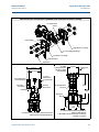
2.11
Rosemount 305, 306, and 304 manifolds
The 305 Integral Manifold is available in two designs: Traditional and Coplanar. The traditional
305 Integral Manifold can be mounted to most primary elements with mounting adapters in the
market today. The 306 Integral Manifold is used with the 3051T in-line transmitters to provide
block-and-bleed valve capabilities of up to 10000 psi (690 bar).
Installation
29
Reference Manual
Section 2: Installation
00809-0100-4001, Rev JA
November 2012
Figure 2-24. Manifolds
3051C AND 304
CONVENTIONAL
3051C AND 305
INTEGRAL TRADITIONAL
30
3051C AND 305 INTEGRAL
COPLANAR
3051T AND 306
IN-LINE
Installation
Reference Manual
Section 2: Installation
00809-0100-4001, Rev JA
2.11.1
November 2012
Rosemount 305 integral manifold installation procedure
To install a 305 Integral Manifold to a 3051 transmitter:
1.
Inspect the PTFE sensor module o-rings. Undamaged o-rings may be reused. If the
o-rings are damaged (if they have nicks or cuts, for example), replace with o-rings
designed for Rosemount transmitter.
Important
If replacing the o-rings, take care not to scratch or deface the o-ring grooves or the surface of
the isolating diaphragm while you remove the damaged o-rings.
2.
Install the Integral Manifold on the sensor module. Use the four 2.25-in. manifold bolts
for alignment. Finger tighten the bolts, then tighten the bolts incrementally in a cross
pattern to final torque value. See “Flange bolts” on page 11 for complete bolt
installation information and torque values. When fully tightened, the bolts should
extend through the top of the sensor module housing.
3.
If the PTFE sensor module o-rings have been replaced, the flange bolts should be
re-tightened after installation to compensate for cold flow of the o-rings.
Note
Always perform a zero trim on the transmitter/manifold assembly after installation to eliminate
mounting effects.
2.11.2
Rosemount 306 integral manifold installation procedure
The 306 Manifold is for use only with a 3051T In-line transmitter.
Assemble the 306 Manifold to the 3051T In-line transmitter with a thread sealant.
2.11.3
Rosemount 304 conventional manifold installation
procedure
To install a 304 Conventional Manifold to a 3051 transmitter:
2.11.4
1.
Align the Conventional Manifold with the transmitter flange. Use the four manifold
bolts for alignment.
2.
Finger tighten the bolts, then tighten the bolts incrementally in a cross pattern to final
torque value. See “Flange bolts” on page 11 for complete bolt installation information
and torque values. When fully tightened, the bolts should extend through the top of
the sensor module housing.
3.
Leak-check assembly to maximum pressure range of transmitter.
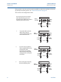
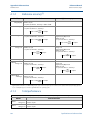
Manifold operation
Improper installation or operation of manifolds may result in process leaks, which may cause
death or serious injury.
See “Safety messages” on page 5 for complete warning information.
Installation
31
Reference Manual
Section 2: Installation
00809-0100-4001, Rev JA
November 2012
Always perform a zero trim on the transmitter/manifold assembly after installation to eliminate
any shift due to mounting effects. See “Sensor Trim Overview” on page 10.
Three and five-valve configurations shown:
In normal operation the two block
valves between the process and
instrument ports will be open and the
equalizing valve will be closed.
L
H
Drain/
Vent Valve
Drain/
Vent
Valve
Equalize
(closed)
Isolate
(open)
Isolate
(open)
Process
1.
To zero the 3051, close the
block valve to the low
pressure (downstream) side
of the transmitter first.
L
H
Drain/
Vent Valve
Drain/
Vent
Valve
Equalize
(closed)
Isolate
(open)
Isolate
(closed)
Process
2.
Open the center (equalize)
valve to equalize the pressure
on both sides of the
transmitter. The manifold
valves are now in the proper
configuration for zeroing the
transmitter.
L
H
Drain/
Vent Valve
Drain/
Vent
Valve
Equalize
(open)
Isolate
(closed)
Isolate
(open)
Process
3.
After zeroing the transmitter,
close the equalizing valve.
L
H
Drain/
Vent Valve
Equalize
(closed)
Drain/
Vent
Valve
Isolate
(closed)
Isolate
(open)
Process
32
Installation
Reference Manual
Section 2: Installation
00809-0100-4001, Rev JA
November 2012
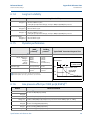
4.
Open the block valve on the
low pressure side of the
transmitter to return the
transmitter to service.
L
H
Drain/
Vent Valve
Drain/
Vent
Valve
Equalize
(closed)
Isolate
(open)
Isolate
(open)
Process
Five-valve Natural Gas configurations shown:
In normal operation, the two block
valves between the process and
instrument ports will be open, and the
equalizing valves will be closed.
L
H
Test
(Plugged)
Test
(Plugged)
Equalize
(closed)
Equalize
(closed)
Isolate
(open)
Isolate
(open)
Process
1.
To zero the 3051, first close
the block valve on the low
pressure (downstream) side
of the transmitter.
Drain
Vent
(closed)
Process
L
H
Test (Plugged)
Test
(Plugged)
Equalize
(closed)
Equalize
(closed)
Isolate
(open)
Process
Isolate
(closed)
Drain Vent
(closed)
Process
Note
Do not open the low side equalize valve before the high side equalize valve. Doing so will
overpressure the transmitter.
Installation
33
Reference Manual
Section 2: Installation
00809-0100-4001, Rev JA
November 2012
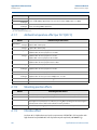
2.
Open the equalize valve on
the high pressure (upstream)
side of the transmitter.
L
H
Test
(Plugged)
Test
(Plugged)
Equalize
(open)
Equalize
(closed)
Isolate
(open)
Isolate
(closed)
Process
3.
Open the equalize valve on
the low pressure
(downstream) side of the
transmitter. The manifold is
now in the proper
configuration for zeroing the
transmitter.
After zeroing the transmitter,
close the equalize valve on
the low pressure
(downstream) side of the
transmitter.
L
Test (Plugged)
Test
(Plugged)
Equalize
(open)
Equalize
(open)
Isolate
(open)
Isolate
(closed)
Drain
Vent
(closed)
Process
L
H
Test
(Plugged)
Test
(Plugged)
Equalize
(open)
Equalize
(closed)
Isolate
(open)
Process
2.12
Process
H
Process
4.
Drain
Vent
(closed)
Isolate
(closed)
Drain
Vent
(closed)
Process
Liquid level measurement
Differential pressure transmitters used for liquid level applications measure hydrostatic pressure
head. Liquid level and specific gravity of a liquid are factors in determining pressure head. This
pressure is equal to the liquid height above the tap multiplied by the specific gravity of the
liquid. Pressure head is independent of volume or vessel shape.
34
Installation
Reference Manual
Section 2: Installation
00809-0100-4001, Rev JA
November 2012
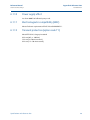
5.
Close the equalize valve on
the high pressure (upstream)
side.
L
H
Test
(Plugged)
Test
(Plugged)
Equalize
(closed)
Equalize
(closed)
Isolate
(open)
Isolate
(closed)
Process
6.
Finally, to return the
transmitter to service, open
the low side isolation valve.
Drain
Vent
(closed)
Process
L
H
Test (Plugged)
Test
(Plugged)
Equalize
(closed)
Equalize
(closed)
Isolate
(open)
Process
2.12.1
Isolate
(open)
Drain
Vent
(closed)
Process
Open vessels
A pressure transmitter mounted near a tank bottom measures the pressure of the liquid above.
Make a connection to the high pressure side of the transmitter, and vent the low pressure side to
the atmosphere. Pressure head equals the liquid’s specific gravity multiplied by the liquid height
above the tap.
Zero range suppression is required if the transmitter lies below the zero point of the desired level
range. Figure 2-25 shows a liquid level measurement example.
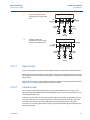
2.12.2
Closed vessels
Pressure above a liquid affects the pressure measured at the bottom of a closed vessel. The
liquid specific gravity multiplied by the liquid height plus the vessel pressure equals the pressure
at the bottom of the vessel.
To measure true level, the vessel pressure must be subtracted from the vessel bottom pressure.
To do this, make a pressure tap at the top of the vessel and connect this to the low side of the
transmitter. Vessel pressure is then equally applied to both the high and low sides of the
transmitter. The resulting differential pressure is proportional to liquid height multiplied by the
liquid specific gravity.
Installation
35
Reference Manual
Section 2: Installation
00809-0100-4001, Rev JA
November 2012
Dry leg condition
Low-side transmitter piping will remain empty if gas above the liquid does not condense. This is
a dry leg condition. Range determination calculations are the same as those described for
bottom-mounted transmitters in open vessels, as shown in Figure 2-25.
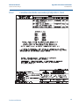
Figure 2-25. Liquid level measurement example.
X
Let X equal the vertical distance between the minimum and maximum
measurable levels (500 in.).
Let Y equal the vertical distance between the transmitter datum line and the
minimum measurable level (100 in.).
Let SG equal the specific gravity of the fluid (0.9).
Let h equal the maximum head pressure to be measured in inches of water.
Let e equal head pressure produced by Y expressed in inches of water.
Let Range equal e to e + h.
Then h = (X)(SG)
= 500 x 0.9
= 450 inH2O
e = (Y)(SG)
= 100 x 0.9
= 90 inH2O
Range = 90 to 540 inH2O
Y
T
20
SUPRESSION
ZERO
mA dc
4
0
90
540
inH2O
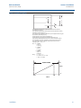
Wet leg condition
Condensation of the gas above the liquid slowly causes the low side of the transmitter piping to
fill with liquid. The pipe is purposely filled with a convenient reference fluid to eliminate this
potential error. This is a wet leg condition.
The reference fluid will exert a head pressure on the low side of the transmitter. Zero elevation of
the range must then be made. See Figure 2-26.
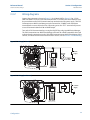
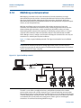
Bubbler system in open vessel
A bubbler system that has a top-mounted pressure transmitter can be used in open vessels. This
system consists of an air supply, pressure regulator, constant flow meter, pressure transmitter,
and a tube that extends down into the vessel.
Bubble air through the tube at a constant flow rate. The pressure required to maintain flow
equals the liquid’s specific gravity multiplied by the vertical height of the liquid above the tube
opening. Figure 2-27 shows a bubbler liquid level measurement example.
36
Installation
Reference Manual
Section 2: Installation
00809-0100-4001, Rev JA
November 2012
Figure 2-26. Wet leg example.
X
Z
Y
LT
H
L
Let X equal the vertical distance between the minimum and maximum
measurable levels (500 in.).
Let Y equal the vertical distance between the transmitter datum line and the
minimum measurable level (50 in.).
Let z equal the vertical distance between the top of the liquid in the wet leg and
the transmitter datum line (600 in.).
Let SG1 equal the specific gravity of the fluid (1.0).
Let SG2 equal the specific gravity of the fluid in the wet leg (1.1).
Let h equal the maximum head pressure to be measured in inches of water.
Let e equal the head pressure produced by Y expressed in inches of water.
Let s equal head pressure produced by z expressed in inches of water.
Let Range equal e – s to h + e – s.
Then h = (X)(SG1)
= 500 x 1.0
= 500 in H2O
e = (Y)(SG1)
= 50 x 1.0
= 50 inH2O
s = (z)(SG2)
= 600 x 1.1
= 660 inH20
Range = e – s to h + e – s.
= 50 – 660 to 500 + 50 – 660
= –610 to –110 inH20
20
ZERO ELEVATION
mA dc
4
-610
-110
0
inH2O
Installation
37
Reference Manual
Section 2: Installation
00809-0100-4001, Rev JA
November 2012
Figure 2-27. Bubbler liquid level measurement example.
AIR
T
X
Let X equal the vertical distance between the minimum and maximum
measurable levels (100 in.).
Let SG equal the specific gravity of the fluid (1.1).
Let h equal the maximum head pressure to be measured in inches of water.
Let Range equal zero to h.
Then h = (X)(SG)
= 100 x 1.1
= 110 inH2O
Range = 0 to 110 inH2O
20
mA dc
4
0
110
inH2O
38
Installation
Section 3: Configuration
Reference Manual
November 2012
00809-0100-4001, Rev JA
Section 3
Configuration
Overview . . . . . . . . . . . . . . . . . . . . . . . . . . . . . . . . . . . . . . . . . . . . . . . . . . . . . . . . . . . . . . . page 39
Safety messages . . . . . . . . . . . . . . . . . . . . . . . . . . . . . . . . . . . . . . . . . . . . . . . . . . . . . . . . . page 39
Commissioning . . . . . . . . . . . . . . . . . . . . . . . . . . . . . . . . . . . . . . . . . . . . . . . . . . . . . . . . . . page 40
Configuration data review . . . . . . . . . . . . . . . . . . . . . . . . . . . . . . . . . . . . . . . . . . . . . . . . page 42
Field communicator menu trees . . . . . . . . . . . . . . . . . . . . . . . . . . . . . . . . . . . . . . . . . . . page 44
Traditional fast key sequence . . . . . . . . . . . . . . . . . . . . . . . . . . . . . . . . . . . . . . . . . . . . . page 48
Check output . . . . . . . . . . . . . . . . . . . . . . . . . . . . . . . . . . . . . . . . . . . . . . . . . . . . . . . . . . . . page 50
Basic setup . . . . . . . . . . . . . . . . . . . . . . . . . . . . . . . . . . . . . . . . . . . . . . . . . . . . . . . . . . . . . . page 52
LCD display . . . . . . . . . . . . . . . . . . . . . . . . . . . . . . . . . . . . . . . . . . . . . . . . . . . . . . . . . . . . . . page 58
Detailed setup . . . . . . . . . . . . . . . . . . . . . . . . . . . . . . . . . . . . . . . . . . . . . . . . . . . . . . . . . . . page 61
Diagnostics and service . . . . . . . . . . . . . . . . . . . . . . . . . . . . . . . . . . . . . . . . . . . . . . . . . . . page 62
Advanced functions . . . . . . . . . . . . . . . . . . . . . . . . . . . . . . . . . . . . . . . . . . . . . . . . . . . . . . page 64
Multidrop communication . . . . . . . . . . . . . . . . . . . . . . . . . . . . . . . . . . . . . . . . . . . . . . . . page 68
3.1
Overview
This section contains information on commissioning and tasks that should be performed on the
bench prior to installation.
Field Communicator and AMS Device Manager instructions are given to perform configuration
functions. For convenience, Field Communicator fast key sequences are labeled “Fast Keys” for
each software function below the appropriate headings.
3.2
Safety messages
Procedures and instructions in this section may require special precautions to ensure the safety
of the personnel performing the operations. Information that raises potential safety issues is
indicated by a warning symbol (
). Refer to the following safety messages before performing
an operation preceded by this symbol.
Configuration
39
Reference Manual
Section 3: Configuration
00809-0100-4001, Rev JA
November 2012
Explosions could result in death or serious injury:
Installation of this transmitter in an explosive environment must be in accordance with the
appropriate local, national, and international standards, codes, and practices. Please review
the approvals section of the 3051 reference manual for any restrictions associated with a
safe installation.
Before connecting a Field Communicator in an explosive atmosphere, ensure the
instruments in the loop are installed in accordance with intrinsically safe or
non-incendive field wiring practices.
In an explosion-proof/flameproof installation, do not remove the transmitter covers
when power is applied to the unit.
Process leaks may cause harm or result in death.
Install and tighten process connectors before applying pressure.
Electrical shock can result in death or serious injury.
3.3
Avoid contact with the leads and terminals. High voltage that may be present on leads
can cause electrical shock.
Commissioning
Commissioning consists of testing the transmitter and verifying transmitter configuration data.
The 3051 transmitters can be commissioned either before or after installation. Commissioning
the transmitter on the bench before installation using a Field Communicator or AMS Device
Manager ensures that all transmitter components are in working order.
To commission on the bench, required equipment includes a power supply, a milliamp meter,
and a Field Communicator or AMS Device Manager. Wire equipment as shown in Figure 3-1 and
Figure 3-2. To ensure successful communication, a resistance of at least 250 ohms must be
present between the Field Communicator loop connection and the power supply. Connect the
Field Communicator leads to the terminals labeled “COMM” on the terminal block.
Set all transmitter hardware adjustments during commissioning to avoid exposing the
transmitter electronics to the plant environment after installation.
When using a Field Communicator, any configuration changes made must be sent to the
transmitter by using the Send key. AMS Device Manager configuration changes are
implemented when the Apply button is clicked.
3.3.1
Setting the loop to manual
Whenever sending or requesting data that would disrupt the loop or change the output of the
transmitter, set the process application loop to manual. The Field Communicator or AMS Device
Manager will prompt you to set the loop to manual when necessary. Acknowledging this
prompt does not set the loop to manual. The prompt is only a reminder; set the loop to manual
as a separate operation.
40
Configuration
Reference Manual
Section 3: Configuration
00809-0100-4001, Rev JA
3.3.2
November 2012
Wiring diagrams
Connect the equipment as shown in Figure 3-1 for 4-20 mA HART or Figure 3-2 for 1-5 Vdc
HART Low Power. To ensure successful communication, a resistance of at least 250 ohms must
be present between the Field Communicator loop connection and the power supply. The Field
Communicator or AMS Device Manager may be connected at “COMM” on the transmitter
terminal block or across the load resistor. Connecting across the “TEST” terminals will prevent
successful communication for 4-20 mA HART output.
Turn on the Field Communicator by pressing the ON/OFF key or log into AMS Device Manager.
The Field Communicator or AMS Device Manager will search for a HART-compatible device and
indicate when the connection is made. If the Field Communicator or AMS Device Manager fail to
connect, it indicates that no device was found. If this occurs, refer to Section 5: Troubleshooting.
Figure 3-1. Wiring (4–20 mA)
24 Vdc
Supply
Current
Meter
RL 250
Figure 3-2. Wiring (Low-Power)
6-14 Vdc
Supply
Voltmeter
Configuration
41
Reference Manual
Section 3: Configuration
00809-0100-4001, Rev JA
November 2012
3.4
Configuration data review
Note
Information and procedures in this section that make use of Field Communicator fast key
sequences and AMS Device Manager assume that the transmitter and communication
equipment are connected, powered, and operating correctly.
The following is a list of factory default configurations. These can be reviewed by using the Field
Communicator or AMS Device Manager.
Field communicator
Traditional 4-20 mA Fast Keys
1, 5
Traditional 1-5 Vdc Fast Keys
1, 5
Device Dashboard Fast Keys
1, 7
Enter the fast key sequence to view the configuration data.
Transmitter Model
Type
Tag
Range
Date
Descriptor
Message
Minimum and Maximum Sensor Limits
Minimum Span
Units
4 and 20 mA points
Output (linear or sq. root)
Damping
Alarm Setting (high, low)
Security Setting (on, off)
Local Zero/Span Keys (enabled, disabled)
Integral Display
Sensor Fill
Isolator Material
Flange (type, material)
O-Ring Material
Drain/Vent
Remote Seal (type, fill fluid, isolator material, number)
Transmitter S/N
Address
Sensor S/N
AMS device manager
Right click on the device and select Configuration Properties from the menu. Select the tabs to
review the transmitter configuration data.
3.5
Field communicator
(Version 1.8)
42
Configuration
Reference Manual
Section 3: Configuration
00809-0100-4001, Rev JA
3.5.1
November 2012
Field communicator user interface
Figure 3-3. Traditional interface
The corresponding Menu Trees can be viewed on page 44 and page 45.
The fast key sequence can be viewed on page 48.
Figure 3-4. Device dashboard
The corresponding Menu Trees can be viewed on page 46 through page 48.
The fast key sequence can be viewed on page 50.
Configuration
43
Section 3: Configuration
3.6
Reference Manual
00809-0100-4001, Rev JA
November 2012
Field communicator menu trees
Figure 3-5. Rosemount 3051 traditional HART menu tree for 4-20 mA HART output
44
Configuration
Reference Manual
00809-0100-4001, Rev JA
Section 3: Configuration
November 2012
Figure 3-6. Rosemount 3051 traditional HART menu tree for 1-5 Vdc low power
Configuration
45
Reference Manual
Section 3: Configuration
00809-0100-4001, Rev JA
November 2012
Figure 3-7. Rosemount 3051 device dashboard menu tree - overview
Home
1 Overview
2 Configure
3 Service Tools
Overview
1 Device Status
2 Comm Status
3 Pressure
4 Analog Output
5 Pressure URV
6 Pressure LRV
7 Device Information
Identification
1 Tag
2 Model
3 Transmitter S/N
4 Date
5 Descriptor
6 Message
Device Information
1 Identification
2 HART
3 Materials of Construction
4 RS Materials of Construction
5 Analog Alarm
6 Security
HART
1 Universal Revision
2 Field Device Revision
3 Hardware Revision
4 Software Revision
Materials of Construction
1 Sensor Config
2 Sensor Range
3 Upper Sensor Limits
4 Lower Sensor Limits
5 Isolator Material
6 Fill Fluid
7 Process Connection
8 Process Connection Matl
9 O-ring Material
Drain/Vent Material
RS Materials of Construction
1 Number of Remote Seals
2 RS Seal
3 RS Fill Fluid
4 RS Isolator Material
Analog Alarm
1 Alarm Direction
2 High Alarm
3 High Saturation
4 Low Saturation
5 Low Alarm
Security
1 Write Protect Status
2 Local Zero/Span
46
Configuration
Reference Manual
Section 3: Configuration
00809-0100-4001, Rev JA
November 2012
Figure 3-8. Rosemount 3051 device dashboard menu tree - configure
Tag, Message, Descriptor, Date, Pressure Units,
Temperature Units, Damping, URV, LRV
Home
1 Overview
2 Configure
3 Service Tools
Configure
1 Guided Setup
2 Manual Setup
Guided Setup
1 Basic Setup
2 Zero
3 Configure Display
Manual Setup
1 Process Variables
2 Analog Output
3 Display
4 HART
5 Security
6 Device Information
Process Variables
1 Pressure Units
2 Damping
3 Transfer Function
4 Temperature Unit
5 Pressure
6 Sensor Temperature
Analog Output
1 Upper Range Value
2 Lower Range Value
3 Analog Output
4 Percent of Range
5 Upper Sensor Limits
6 Lower Sensor Limits
7 Minimum Span
8 Range by Applying Pressure
Display
1 Display Option
2 Decimal Places
3 Upper Range Value
4 Lower Range Value
5 Transfer Function
6 Units
HART
1 Burst Mode
2 Burst Option
3 Polling Address
Burst Option
PV
% range/current
Process Vars/current
Process Variables
Security
1 Write Protect Status
2 Local Zero/Span
Device Information
1 Identification
2 Flange
3 Remote Seal
Identification
1 Tag
2 Model
3 Transmitter S/N
4 Date
5 Descriptor
6 Message
Flange
1 Process Connection
2 Process Conn matl
3 O-ring Material
4 Drain/Vent Material
Remote Seal
1 Number of Remote Seals
2 RS Seal
3 RS Fill Fluid
4 RS Isolator Material
Configuration
47
Reference Manual
Section 3: Configuration
00809-0100-4001, Rev JA
November 2012
Figure 3-9. Rosemount 3051 device dashboard menu tree - service tools
Home
1 Overview
2 Configure
3 Service Tools
Service Tools
1 Alerts
2 Variables
3 Trends
4 Maintenance
5 Simulate
Alerts
1 Refresh Alerts
Variables
1 Variable Summary
2 Pressure
3 Analog Output
4 Sensor Temperature
Trends
1 Pressure
2 Sensor Temperature
Maintenance
1 Pressure Calibration
2 Analog Calibration
3 Recall Factory Calibration
Simulate
1 Loop Test
3.7
Only Active Alerts show up here
Trend Graph
Pressure Calibration
1 Upper
2 Lower
3 Zero
4 Upper Cal Pt
5 Lower Cal Pt
6 Upper Sensor Limits
7 Lower Sensor Limits
Traditional fast key sequence
A check (⻫) indicates the basic configuration parameters. At minimum, these parameters should
be verified as part of the configuration and startup procedure.
Table 3-1. 3051 Traditional fast key sequence
Function
⻫
1-5 Vdc HART
low power
Alarm and Saturation Levels
1, 4, 2, 7
N/A
Analog Output Alarm Type
1, 4, 3, 2, 4
1, 4, 3, 2, 4
Burst Mode Control
1, 4, 3, 3, 3
1, 4, 3, 3, 3
Burst Operation
1, 4, 3, 3, 4
1, 4, 3, 3, 4
1, 3, 7, 2
N/A
Custom Meter Configuration
48
4-20 mA HART
Configuration
Reference Manual
Section 3: Configuration
00809-0100-4001, Rev JA
November 2012
Function
Custom Meter Value
⻫
N/A
1, 3, 6
1, 3, 6
Date
1, 3, 4, 1
1, 3, 4, 1
Descriptor
1, 3, 4, 2
1, 3, 4, 2
Digital To Analog Trim (4-20 mA Output)
1, 2, 3, 2, 1
1, 2, 3, 2, 1
Disable Local Span/Zero Adjustment
1, 4, 4, 1, 7
1, 4, 4, 1, 7
Field Device Information
1, 4, 4, 1
1, 4, 4, 1
Full Trim
1, 2, 3, 3
1, 2, 3, 3
Keypad Input – Rerange
1, 2, 3, 1, 1
1, 2, 3, 1, 1
Local Zero and Span Control
1, 4, 4, 1, 7
1, 4, 4, 1, 7
1, 2, 2
1, 2, 2
1, 2, 3, 3, 2
1, 2, 3, 3, 2
Message
1, 3, 4, 3
1, 3, 4, 3
Meter Options
1, 4, 3, 4
N/A
Number of Requested Preambles
1, 4, 3, 3, 2
1, 4, 3, 3, 2
Poll Address
1, 4, 3, 3, 1
1, 4, 3, 3, 1
Left Arrow, 4, 1, 1
Left Arrow, 4, 1, 1
1, 3, 3
1, 3, 3
1, 2, 3, 1
1, 2, 3, 1
1, 2, 3, 2, 2
1, 2, 3, 2, 2
Self Test (Transmitter)
1, 2, 1, 1
1, 2, 1, 1
Sensor Info
1, 4, 4, 2
1, 4, 4, 2
1, 1, 4
1, 1, 4
1, 2, 3, 3, 4
1, 2, 3, 3, 4
1, 2, 1, 2
1, 2, 1, 2
Damping
Lower Sensor Trim
Poll a Multidropped Transmitter
Range Values
Rerange
Scaled D/A Trim (4–20 mA Output)
Sensor Temperature
Sensor Trim Points
Status
⻫
Tag
1, 3, 1
1, 3, 1
⻫
Transfer Function (Setting Output Type)
1, 3, 5
1, 3, 5
Transmitter Security (Write Protect)
1, 3, 4, 4
1, 3, 4, 4
Trim Analog Output
1, 2, 3, 2
1, 2, 3, 2
1, 3, 2
1, 3, 2
Upper Sensor Trim
1, 2, 3, 3, 3
1, 2, 3, 3, 3
Zero Trim
1, 2, 3, 3, 1
1, 2, 3, 3, 1
⻫
Configuration
1-5 Vdc HART
low power
1, 4, 3, 4, 3
Loop Test
⻫
4-20 mA HART
Units (Process Variable)
49
Reference Manual
Section 3: Configuration
00809-0100-4001, Rev JA
November 2012
Table 3-2. 3051 device dashboard fast key sequence
Function
Alarm and Saturation Levels
1, 7, 5
Analog Output Alarm Type
1, 7, 5
Burst Mode Control
2, 2, 4, 1
Burst Option
2, 2, 4, 2
Custom Display Configuration
Damping
2, 2, 3
2, 2, 1, 2
Date
2, 2, 6, 1, 4
Descriptor
2, 2, 6, 1, 5
Digital to Analog Trim (4 - 20 mA Output)
Disable Zero & Span Adjustment
3, 4, 2
2, 2, 5, 2
Field Device Information
2, 2, 6
Loop Test
3, 5, 1
Lower Sensor Trim
Message
3, 4, 1, 2
2, 2, 6, 1, 6
Poll Address
2, 2, 4, 3
Range Values
1, 5
Rerange with Keypad
1, 5
Scaled D/A Trim (4 - 20 mA Output)
3, 4, 2
Sensor Temperature/Trend
3, 3, 2
Tag
3.8
4-20 mA HART
2, 2, 6, 1, 1
Transfer Function
2, 2, 1, 3
Transmitter Security (Write Protect)
2, 2, 5, 1
Units
2, 2, 1, 1
Upper Sensor Trim
3, 4, 1, 1
Zero Trim
3, 4, 1, 3
Check output
Before performing other transmitter on-line operations, review the digital output parameters to
ensure that the transmitter is operating properly and is configured to the appropriate process
variables.
50
Configuration
Reference Manual
Section 3: Configuration
00809-0100-4001, Rev JA
3.8.1
November 2012
Process variables
The process variables for the 3051 provide transmitter output, and are continuously updated.
The pressure reading in both engineering units and percent of range will continue to track with
pressures outside of the defined range from the lower to the upper range limit of the sensor
module.
Field communicator
Traditional 4-20 mA Fast Keys
1, 1
Traditional 1-5 Vdc Fast Keys
1, 1
Device Dashboard Fast Keys
3, 2
The process variable menu displays the following process variables:
Pressure
Percent of range
Analog output
AMS device manager
Right click on the device and select Process Variables... from the menu.The Process Variable
screen displays the following process variables:
3.8.2
Pressure
Percent of range
Analog output
Sensor temperature
The 3051 contains a temperature sensor near the pressure sensor in the sensor module. When
reading this temperature, keep in mind the sensor is not a process temperature reading.
Field communicator
Traditional 4-20 mA Fast Keys
1, 1, 4
Traditional 1-5 Vdc Fast Keys
1, 1, 4
Device Dashboard Fast Keys
3, 2, 4
Enter the fast key sequence “Sensor Temperature” to view the sensor temperature reading.
AMS device manager
Right click on the device and select Process Variables... from the menu. “Snsr Temp” is the
sensor temperature reading.
Configuration
51
Reference Manual
Section 3: Configuration
00809-0100-4001, Rev JA
November 2012
3.9
Basic setup
3.9.1
Set process variable units
The PV Unit command sets the process variable units to allow you to monitor your process using
the appropriate units of measure.
Field communicator
Traditional 4-20 mA Fast Keys
1, 3, 2
Traditional 1-5 Vdc Fast Keys
1, 3, 2
Device Dashboard Fast Keys
2, 2, 1, 1
Enter the fast key sequence “Set Process Variable Units.” Select from the following engineering
units:
inH2O
bar
inHg
mbar
ftH2O
g/cm
2
mmH2O
kg/cm
mmHg
Pa
psi
kPa
2
torr
atm
inH2O at 4 °C
mmH2O at 4 °C
AMS device manager
Right click on the device and select Configure from the menu. In the Basic Setup tab, select Unit
from the drop down menu to select units.
3.9.2
Set output (Transfer function)
The 3051 has two output settings: Linear and Square Root. Activate the square root output
option to make analog output proportional to flow. As input approaches zero, the 3051
automatically switches to linear output in order to ensure a more smooth, stable output near
zero (see Figure 3-10).
For 4-20 mA HART output, the slope of the curve is unity (y = x) from 0 to 0.6 percent of the
ranged pressure input. This allows accurate calibration near zero. Greater slopes would cause
large changes in output (for small changes at input). From 0.6 percent to 0.8 percent, curve
slope equals 42 (y = 42x) to achieve continuous transition from linear to square root at the
transition point.
52
Configuration
Reference Manual
Section 3: Configuration
00809-0100-4001, Rev JA
November 2012
Field communicator
Traditional 4-20 mA Fast Keys
1, 3, 5
Traditional 1-5 Vdc Fast Keys
1, 3, 5
Device Dashboard Fast Keys
2, 2, 1, 3
AMS device manager
Right click on the device and select Configure from the menu.
1.
In the Basic Setup tab, use Xfer fnctn drop down menu to select output, click Apply.
2.
After carefully reading the warning provided, select yes.
Figure 3-10. 4-20 mA HART square root output transition point
Full Scale
Output
(mA dc)
Full Scale
Flow (%)
Sq. Root
Curve
Sq. Root Curve
Transition Point
Transition Point
Linear Section
Slope=42
Slope=1
Note
For a flow turndown of greater than 10:1 it is not recommended to perform a square root
extraction in the transmitter. Instead, perform the square root extraction in the system.
3.9.3
Rerange
The Range Values command sets each of the lower and upper range analog values (4 and 20 mA
points and 1 and 5 Vdc points) to a pressure. The lower range point represents 0% of range and
the upper range point represents 100% of range. In practice, the transmitter range values may
be changed as often as necessary to reflect changing process requirements. For a complete
listing of Range & Sensor limits, refer to “Range and sensor limits” on page 108.
Configuration
53
Reference Manual
Section 3: Configuration
00809-0100-4001, Rev JA
November 2012
Note
Transmitters are shipped from Emerson Process Management fully calibrated per request or by
the factory default of full scale (zero to upper range limit).
Note
Regardless of the range points, the 3051 will measure and report all readings within the digital
limits of the sensor. For example, if the 4 and 20 mA points are set to 0 and 10 inH2O, and the
transmitter detects a pressure of 25 inH2O, it digitally outputs the 25 inH2O reading and a 250%
of range reading.
Select from one of the methods below to rerange the transmitter. Each method is unique;
examine all options closely before deciding which method works best for your process.
Rerange with a Field Communicator or AMS Device Manager only.
Rerange with a pressure input source and a Field Communicator or AMS Device
Manager.
Rerange with a pressure input source and the local zero and span buttons (option D4).
Note
If the transmitter security switch is ON, adjustments to the zero and span will not be able to be
made. Refer to “Configure security and alarm” on page 20 for security information.
Rerange with a Field Communicator or AMS Device Manager Only.
The easiest and most popular way to rerange is to use the Field Communicator only. This
method changes the range values of the analog 4 and 20 mA points (1 and 5 Vdc points)
independently without a pressure input. This means that when you change either the 4 or 20
mA setting, you also change the span.
An example for the 4-20 mA HART output:
If the transmitter is ranged so that
4 mA = 0 inH2O, and
20 mA = 100 inH2O,
and you change the 4 mA setting to 50 inH2O using the communicator only, the new settings
are:
4 mA = 50 inH2O, and
20 mA = 100 inH2O.
Note that the span was also changed from 100 inH2O to 50 inH2O, while the 20 mA setpoint
remained at 100 inH2O.
To obtain reverse output, simply set the 4 mA point at a greater numerical value than the 20 mA
point. Using the above example, setting the 4 mA point at 100 inH2O and the 20 mA point at 0
inH2O will result in reverse output.
54
Configuration
Reference Manual
Section 3: Configuration
00809-0100-4001, Rev JA
November 2012
Field communicator
Traditional 4-20 mA Fast Keys
1, 2, 3, 1
Traditional 1-5 Vdc Fast Keys
1, 2, 3, 1
Device Dashboard Fast Keys
2, 2, 2, 1
From the HOME screen, enter the fast key sequence “Rerange with a Communicator Only.”
AMS device manager
Right click on the device and select Configure from the menu. In the Basic Setup tab, locate the
Analog Output box and perform the following procedure:
1.
Enter the lower range value (LRV) and the upper range value (URV) in the fields
provided. Click Apply.
2.
After carefully reading the warning provided, select yes.
Rerange with a pressure input source and a field communicator
or AMS device manager
Reranging using the Field Communicator and applied pressure is a way of reranging the
transmitter when specific 4 and 20 mA points (1 and 5 Vdc points) are not calculated.
Note
The span is maintained when the 4 mA point (1 Vdc point) is set. The span changes when the
20 mA point (5 Vdc point) is set. If the lower range point is set to a value that causes the upper
range point to exceed the sensor limit, the upper range point is automatically set to the sensor
limit, and the span is adjusted accordingly.
Field communicator
Traditional 4-20 mA Fast Keys
1, 2, 3, 1, 2
Traditional 1-5 Vdc Fast Keys
1, 2, 3, 1, 2
Device Dashboard Fast Keys
2, 2, 2, 8
From the HOME screen, enter the fast key sequence Rerange with a pressure input source and a
field communicator or AMS device manager .
Configuration
55
Reference Manual
Section 3: Configuration
00809-0100-4001, Rev JA
November 2012
AMS device manager
Right click on the device, select Calibrate, then Apply values from the menu.
1.
Select Next after the control loop is set to manual.
2.
From the Apply Values menu, follow the on-line instructions to configure lower and
upper range values.
3.
Select Exit to leave the Apply Values screen.
4.
Select Next to acknowledge the loop can be returned to automatic control.
5.
Select Finish to acknowledge the method is complete.
Rerange with a pressure input source and the local zero and
span buttons (option D4)
Reranging using the local zero and span adjustments (see Figure 3-11 on page 57) and a
pressure source is a way of reranging the transmitter when specific 4 and 20 mA (1 and 5 Vdc)
points are not known and a communicator is not available.
Note
When you set the 4 mA (1 Vdc) point the span is maintained; when you set the 20 mA (5 Vdc)
point the span changes. If you set the lower range point to a value that causes the upper range
point to exceed the sensor limit, the upper range point is automatically set to the sensor limit,
and the span is adjusted accordingly.
To rerange the transmitter using the span and zero buttons, perform the following procedure:
56
1.
Loosen the screw holding the certifications label on the top of the transmitter housing.
Slide the label to expose the zero and span buttons. See Figure 3-11.
2.
Apply the desired 4 mA (1 Vdc) pressure value to the transmitter. Push and hold the
zero adjustment button for at least two seconds but no longer than ten seconds.
3.
Apply the desired 20 mA (5 Vdc) pressure value to the transmitter. Push and hold the
span adjustment button for at least two seconds but no longer than ten seconds.
Configuration
Reference Manual
Section 3: Configuration
00809-0100-4001, Rev JA
November 2012
Figure 3-11. Zero and span buttons
Span and Zero Adjustment Buttons
Note
The span is maintained when the 4 mA point (1 Vdc point) is set. The span changes when the
20 mA point (5 Vdc point) is set. If the lower range point is set to a value that causes the upper
range point to exceed the sensor limit, the upper range point is automatically set to the sensor
limit, and the span is adjusted accordingly.
3.9.4
Damping
The “Damp” command introduces a delay in the micro-processing which increases the response
time of the transmitter; smoothing variations in output readings caused by rapid input changes.
Determine the appropriate damping setting based on the necessary response time, signal
stability, and other requirements of the loop dynamics within your system. The default damping
value is 0.4 seconds and it can be set to any of ten pre-configured damping values between 0
and 25.6 seconds. See list below.
0.00 seconds
0.05 seconds
0.10 seconds
0.20 seconds
0.40 seconds
0.80 seconds
1.60 seconds
3.20 seconds
6.40 seconds
12.8 seconds
25.6 seconds
The current damping value can be determined by executing the Field Communicator fast keys
or going to “Configure” in AMS Device Manager.
Configuration
57
Reference Manual
Section 3: Configuration
00809-0100-4001, Rev JA
November 2012
Field communicator
Traditional 4-20 mA Fast Keys
1, 3, 6
Traditional 1-5 Vdc Fast Keys
1, 3, 6
Device Dashboard Fast Keys
2, 2, 1, 2
AMS device manager
Right click on the device and select Configure from the menu.
3.10
1.
In the Basic Setup tab, enter the damping value in the Damp field, click Apply.
2.
After carefully reading the warning provided, select yes.
LCD display
The LCD display connects directly to the interface board which maintains direct access to the
signal terminals. The display indicates output and abbreviated diagnostic messages. A display
cover is provided to accommodate the display.
For 4-20 mA HART output, the LCD display features a two-line display. The first line of five
characters displays the actual measured value, the second line of six characters displays the
engineering units. The LCD can also display diagnostic messages. Refer to Figure 3-12.
For 1-5 Vdc HART Low Power output, the LCD display features a single-line display with four
characters that display the actual value. The LCD can also display diagnostic messages. Refer to
Figure 3-12.
Figure 3-12.
4-20 mA HART
58
1-5 Vdc HART Low Power
Configuration
Reference Manual
Section 3: Configuration
00809-0100-4001, Rev JA
3.10.1
November 2012
LCD display configuration for 4-20 mA HART only
The factory default alternates are between Engineering Units and % of Range. The LCD Display
Configuration command allows customization of the LCD display to suit application
requirements. The LCD display will alternate between the selected items:
Eng. Units only
Alternate Eng. Units & % of Range
% of Range only
Alternate Eng. Units & Custom Display
Custom Display only
Alternate % of Range & Custom Display
Field communicator
Traditional 4-20 mA Fast Keys
1, 3, 7
Device Dashboard Fast Keys
2, 2, 3
To change the standard default to one of the above options, follow these steps:
1.
From the communicators main menu select (1) Device Setup, (3) Basic Setup, (7) Meter
Options.
2.
Select (1) Meter Type. Using the up or down arrows scroll up or down until the desired
display has been highlighted. Press ENTER, SEND, and HOME.
AMS
Right click on the device and select Configuration Properties from the menu.
3.10.2
1.
In the Local Display tab, locate the Meter Type area. Select the desired options to suit
your application needs, click Apply.
2.
An Apply Parameter Modification screen appears, enter desired information and click OK.
3.
After carefully reading the warning provided, select OK.
Custom display configuration 4-20 mA HART only
The user-configurable scale is a feature that enables the LCD display to display flow, level, or
custom pressure units. With this feature you can define the decimal point position, the upper
range value, the lower range value, the engineering units, and the transfer function.The display
can be configured using a Field Communicator or AMS.
The user-configurable scale feature can define:
Configuration
decimal point position
upper range values
lower range values
engineering units
transfer function
59
Reference Manual
Section 3: Configuration
00809-0100-4001, Rev JA
November 2012
To configure the display with a Field Communicator, perform the following procedure:
1.
Change the Meter Type to “Custom Meter” by using the Fast Key sequence under “LCD
display configuration for 4-20 mA HART only” on page 59.
2.
Next from the ONLINE screen, Select 1 Device Setup, 3 Basic Setup, 7 Meter Options, 2
Meter Options, 2 Custom Meter Setup.
3.
To specify decimal point position:
a.
Select 1 Sel dec pt pos. Choose the decimal point representation that will provide the
most accurate output for your application. For example, when outputting between 0
and 75 GPM, choose XX.XXX or use the decimal point examples below:
XXXXX
XXXX.X
XXX.XX
XX.XXX
X.XXXX
Note
Make sure the selection has been sent and the decimal point has changed before proceeding to
the next step.
b. SEND
4.
To specify a custom upper range value:
a.
Select 2 CM Upper Value. Type the value that you want the transmitter to read at the
20 mA point.
b. SEND
5.
To specify a custom lower range value:
a.
Select 3 CM Lower Value. Type the value that you want the transmitter to read at the
4 mA point.
b. SEND
6.
To define custom units:
a.
Select 4 CM Units. Enter the custom units (five characters maximum) that you want the
display to display.
b. SEND
7.
To choose the transmitter transfer function for the display:
a.
8.
Select 5 CM xfer fnct. Enter the transmitter transfer function for the display. Select sq
root to display flow units. The custom meter transfer function is independent of the
analog output transfer function.
Select SEND to upload the configuration to the transmitter.
See “Safety messages” on page 39 for complete warning information.
60
Configuration
Reference Manual
Section 3: Configuration
00809-0100-4001, Rev JA
November 2012
3.11
Detailed setup
3.11.1
Failure mode alarm and saturation
The 3051 transmitters automatically and continuously perform self-diagnostic routines. If the
self-diagnostic routines detect a failure, the transmitter drives its output outside of the normal
saturation values. The transmitter will drive its output low or high based on the position of the
failure mode alarm jumper. See Table 3-3, Table 3-4, and Table 3-5 for failure mode and
saturation output levels. To select alarm position, see “Configure security and alarm” on
page 20.
Table 3-3. 4-20 mA HART alarm and saturation values
Level
4–20 mA saturation
4–20 mA alarm
Low
3.9 mA
3.75 mA
High
20.8 mA
21.75 mA
Table 3-4. NAMUR-Compliant alarm and saturation values
Level
4–20 mA saturation
4–20 mA alarm
Low
3.8 mA
3.6 mA
High
20.5 mA
22.5 mA
Table 3-5. 1-5 Vdc HART low-power alarm and saturation values
Level
1–5 V saturation
1–5 V alarm
Low
0.97 V
0.95 V
High
5.20 V
5.4 V
Caution
Alarm level values will be affected by analog trim. Refer to “Analog output trim” on page 77.
Note
When a transmitter is in an alarm condition, the Field Communicator indicates the analog
output the transmitter would drive if the alarm condition did not exist. The transmitter will
alarm high in the event of failure if the alarm jumper is removed.
Configuration
61
Reference Manual
Section 3: Configuration
00809-0100-4001, Rev JA
November 2012
3.11.2
Alarm and saturation levels for burst mode
Transmitters set to burst mode handle saturation and alarm conditions differently.
Alarm conditions:
Analog output switches to alarm value
Primary variable is burst with a status bit set
Percent of range follows primary variable
Temperature is burst with a status bit set
Saturation:
3.11.3
Analog output switches to saturation value
Primary variable is burst normally
Temperature is burst normally
Alarm and saturation values for multidrop mode
Transmitters set to multidrop mode handle saturation and alarm conditions differently.
Alarm conditions:
Primary variable is sent with a status bit set
Percent of range follows primary variable
Temperature is sent with a status bit set
Saturation:
3.11.4
Primary variable is sent normally
Temperature is sent normally
Alarm level verification
If the transmitter electronics board, sensor module, or LCD display is repaired or replaced, verify
the transmitter alarm level before returning the transmitter to service. This feature is also useful
in testing the reaction of the control system to a transmitter in an alarm state. To verify the
transmitter alarm values, perform a loop test and set the transmitter output to the alarm value
(see Tables 3-3, 3-4, and 3-5 on page 61, and “Loop test” on page 62).
3.12
Diagnostics and service
Diagnostics and service functions listed below are primarily for use after field installation. The
Loop Test feature is designed to verify proper loop wiring and transmitter output.
3.12.1
Loop test
The Loop Test command verifies the output of the transmitter, the integrity of the loop, and the
operations of any recorders or similar devices installed in the loop.
62
Configuration
Reference Manual
Section 3: Configuration
00809-0100-4001, Rev JA
November 2012
Field communicator
Traditional 4-20 mA Fast Keys
1, 2, 2
Traditional 1-5 Vdc Fast Keys
1, 2, 2
Device Dashboard Fast Keys
3, 5, 1
To initiate a loop test, perform the following procedure:
1.
a. For 4-20 mA HART output, connect a reference meter to the transmitter by either
connecting the meter to the test terminals on the terminal block, or shunting
transmitter power through the meter at some point in the loop.
b. For 1-5 Vdc Low Power HART output, connect a reference meter to the Vout terminal.
2.
From the HOME screen, enter the fast key sequence “Loop Test” to verify the output of
the transmitter.
3.
Select OK after the control loop is set to manual (see “Setting the loop to manual” on
page 40).
4.
Select a discrete milliamp level for the transmitter to output. At the CHOOSE ANALOG
OUTPUT prompt select 1: 4mA (1 Vdc), select 2: 20mA (5 Vdc), or select 3: “Other” to
manually input a value.
a.
If you are performing a loop test to verify the output of a transmitter, enter a value
between 4 and 20 mA (1 and 5 Vdc).
b. If you are performing a loop test to verify alarm levels, enter the value representing an
alarm state (see Tables 3-3, 3-4, and 3-5 on page 61).
5.
Check that the reference meter displays the commanded output value.
a.
If the values match, the transmitter and the loop are configured and functioning
properly.
b. If the values do not match, the meter may be attached to the wrong loop, there may be
a fault in the wiring or power supply, the transmitter may require an output trim, or the
reference meter may be malfunctioning.
After completing the test procedure, the display returns to the Loop Test screen to choose
another output value or to end loop testing.
Configuration
63
Reference Manual
Section 3: Configuration
00809-0100-4001, Rev JA
November 2012
AMS device manager
Right click on the device and select Diagnostics and Test, then Loop Test from the menu.
1.
a. For 4-20 mA HART output, connect a reference meter to the transmitter by either
connecting the meter to the test terminals on the terminal block, or shunting
transmitter power through the meter at some point in the loop.
b. For 1-5 Vdc Low Power HART output, connect a reference meter to the Vout terminal.
2.
Click Next after setting the control loop to manual.
3.
Select desired analog output level. Click Next.
4.
Click Next to acknowledge output being set to desired level.
5.
Check that the reference meter displays the commanded output value.
a.
If the values match, the transmitter and the loop are configured and functioning
properly.
b. If the values do not match, the meter may be attached to the wrong loop, there may be
a fault in the wiring or power supply, the transmitter may require an output trim, or the
reference meter may be malfunctioning.
After completing the test procedure, the display returns to the Loop Test screen to choose
another output value or to end loop testing.
6.
Select End and click Next to end loop testing.
7.
Select Next to acknowledge the loop can be returned to automatic control.
8.
Select Finish to acknowledge the method is complete.
3.13
Advanced functions
3.13.1
Saving, recalling, and cloning configuration data
Use the cloning feature of the Field Communicator or the AMS Device Manager “User
Configuration” feature to configure several 3051 transmitters similarly. Cloning involves
configuring a transmitter, saving the configuration data, then sending a copy of the data to a
separate transmitter. Several possible procedures exist when saving, recalling, and cloning
configuration data. For complete instructions refer to the Field Communicator manual
(publication no. 00809-0100-4276) or AMS Device Manager on-line guides. One common
method is as follows:
64
Configuration
Reference Manual
Section 3: Configuration
00809-0100-4001, Rev JA
November 2012
Field communicator
Traditional 4-20 mA Fast Keys
left arrow, 1, 2
Traditional 1-5 Vdc Fast Keys
left arrow, 1, 2
Device Dashboard Fast Keys
3, 4, 3
1.
Completely configure the first transmitter.
2.
Save the configuration data:
a.
Select SAVE from the Field Communicator HOME/ONLINE screen.
b. Ensure that the location to which the data will be saved is set to MODULE. If it is not,
select 1: Location to set the save location to MODULE.
c.
Select 2: Name, to name the configuration data. The default is the transmitter tag
number.
d. Ensure that the data type is set to STANDARD. If the data type is NOT STANDARD,
select 3: Data Type to set the data type to STANDARD.
e.
Select SAVE.
3.
Connect and power the receiving transmitter and Field Communicator.
4.
Select the back arrow from the HOME/ONLINE screen. The Field Communicator menu
appears.
5.
Select 1: Offline, 2: Saved Configuration, 1: Module Contents to reach the MODULE
CONTENTS menu.
6.
Use the DOWN ARROW to scroll through the list of configurations in the memory
module, and use the RIGHT ARROW to select and retrieve the required configuration.
7.
Select 1: Edit.
8.
Select 1: Mark All.
9.
Select SAVE.
10.
Use the DOWN ARROW to scroll through the list of configurations in the memory
module, and use the RIGHT ARROW to select the configuration again.
11.
Select 3: Send to download the configuration to the transmitter.
12.
Select OK after the control loop is set to manual.
13.
After the configuration has been sent, select OK to acknowledge that the loop can be
returned to automatic control.
When finished, the Field Communicator informs you of the status. Repeat Steps 3 through 13 to
configure another transmitter.
Configuration
65
Reference Manual
Section 3: Configuration
00809-0100-4001, Rev JA
November 2012
Note
The transmitter receiving cloned data must have the same software version (or later) as the
original transmitter.
AMS device manager creating a reusable copy
To create a reusable copy of a configuration perform the following procedure:
1.
Completely configure the first transmitter.
2.
Select View then User Configuration View from the menu bar (or click the toolbar
button).
3.
In the User Configuration window, right click and select New from the context menu.
4.
In the New window, select a device from the list of templates shown, and click OK.
5.
The template is copied into the User Configurations window, with the tag name
highlighted; rename it as appropriate and press Enter.
Note
A device icon can also be copied by dragging and dropping a device template or any other
device icon from AMS Device Manager Explorer or Device Connection View into the User
Configurations window.
The “Compare Configurations” window appears, showing the Current values of the copied
device on one side and mostly blank fields on the other (User Configuration) side.
6.
Transfer values from the current configuration to the user configuration as appropriate
or enter values by typing the values into the available fields.
7.
Click Apply to apply the values, or click OK to apply the values and close the window.
AMS device manager applying a user configuration
Any amount of user configurations can be created for the application. They can also be saved,
and applied to connected devices or to devices in the Device List or Plant Database.
Note
When using AMS Device Manager Revision 6.0 or later, the device to which the user
configuration is applied, must be the same model type as the one created in the user
configuration. When using AMS Device Manager Revision 5.0 or earlier, the same model type
and revision number are required.
To apply a user configuration perform the following procedure:
66
Configuration
Reference Manual
Section 3: Configuration
00809-0100-4001, Rev JA
3.13.2
November 2012
1.
Select the desired user configuration in the User Configurations window.
2.
Drag the icon onto a like device in AMS Device Manager Explorer or Device Connection
View. The Compare Configurations window opens, showing the parameters of the
target device on one side and the parameters of the user configuration on the other.
3.
Transfer parameters from the user configuration to the target device as desired. Click
OK to apply the configuration and close the window.
Burst mode
When configured for burst mode, the 3051 provides faster digital communication from the
transmitter to the control system by eliminating the time required for the control system to
request information from the transmitter. Burst mode is compatible with the analog signal.
Because the HART protocol features simultaneous digital and analog data transmission, the
analog value can drive other equipment in the loop while the control system is receiving the
digital information. Burst mode applies only to the transmission of dynamic data (pressure and
temperature in engineering units, pressure in percent of range, and/or analog output), and does
not affect the way other transmitter data is accessed.
Access to information other than dynamic transmitter data is obtained through the normal
poll/response method of HART communication. A Field Communicator, AMS Device Manager or
the control system may request any of the information that is normally available while the
transmitter is in burst mode. Between each message sent by the transmitter, a short pause
allows the Field Communicator, AMS Device Manager or a control system to initiate a request.
The transmitter will receive the request, process the response message, and then continue
“bursting” the data approximately three times per second.
Field communicator
Traditional 4-20 mA Fast Keys
1, 4, 3, 3, 3
Traditional 1-5 Vdc Fast Keys
1, 4, 3, 3, 3
Device Dashboard Fast Keys
2, 2, 4, 1
AMS device manager
Right click on the device and select Configure from the menu.
1.
Configuration
In the HART tab, use the drop down menu to select “Burst Mode ON or OFF.” For “Burst
option” select the desired properties from the drop down menu. Burst options are as
follows:
–
PV
–
% range/current
–
Process vars/crnt
–
Process variables
2.
After selecting options click Apply.
3.
After carefully reading the warning provided, select yes.
67
Reference Manual
Section 3: Configuration
00809-0100-4001, Rev JA
November 2012
3.14
Multidrop communication
Multidropping transmitters refers to the connection of several transmitters to a single
communications transmission line. Communication between the host and the transmitters
takes place digitally with the analog output of the transmitters deactivated. With smart
communications protocol, up to fifteen transmitters can be connected on a single twisted pair
of wires, or over leased phone lines.
Multidrop installation requires consideration of the update rate necessary from each
transmitter, the combination of transmitter models, and the length of the transmission line.
Communication with transmitters can be accomplished with HART modems and a host
implementing HART protocol. Each transmitter is identified by a unique address (1–15) and
responds to the commands defined in the HART protocol. Field Communicators and AMS
Device Manager can test, configure, and format a multidropped transmitter the same way as a
transmitter in a standard point-to-point installation.
Figure 3-13 shows a typical multidrop network. This figure is not intended as an installation
diagram.
Note
A transmitter in multidrop mode has the analog output fixed at 4 mA. If an LCD display is
installed to a transmitter in multidrop mode, it will alternate the display between “current fixed”
and the specified LCD display output(s).
Figure 3-13. Typical multidrop network
HART Modem
Power
Supply
The 3051 is set to address zero (0) at the factory, which allows operation in the standard
point-to-point manner with a 4–20 mA output signal. To activate multidrop communication,
the transmitter address must be changed to a number from 1 to 15. This change deactivates the
4–20 mA analog output, sending it to 4 mA. It also disables the failure mode alarm signal, which
is controlled by the upscale/downscale switch position. Failure signals in multidropped
transmitters are communicated through HART messages.
68
Configuration
Reference Manual
Section 3: Configuration
00809-0100-4001, Rev JA
3.15
November 2012
Changing a transmitter address
To activate multidrop communication, the transmitter poll address must be assigned a number
from 1 to 15, and each transmitter in a multidropped loop must have a unique poll address.
Field communicator
Traditional 4-20 mA Fast Keys
1, 4, 3, 3, 1
Traditional 1-5 Vdc Fast Keys
1, 4, 3, 3, 1
Device Dashboard Fast Keys
1, 2
AMS device manager
Right click on the device and select Configuration Properties from the menu.
3.15.1
1.
In the HART tab, in the ID box, enter poll address located in the Poll addr box, click Apply.
2.
After carefully reading the warning provided, select yes.
Communicating with a multidropped transmitter
Field communicator
Traditional 4-20 mA Fast Keys
1, 4, 3, 3, 2
Traditional 1-5 Vdc Fast Keys
1, 4, 3, 3, 2
Device Dashboard Fast Keys
1, 2
To communicate with a multidropped transmitter, configure the Field Communicator to poll for
a non-zero address.
1.
From the HOME screen, enter the fast key sequence “Communicating with a
Multidropped Transmitter.”
2.
On the polling menu, scroll down and select “Digital Poll.” In this mode, the Field
Communicator automatically polls for devices at addresses 0-15 upon start up.
AMS device manager
Click on the HART modem icon and select Scan All Devices.
3.15.2
Polling a multidropped transmitter
Polling a multidropped loop determines the model, address, and number of transmitters on the
given loop.
Configuration
69
Section 3: Configuration
Reference Manual
00809-0100-4001, Rev JA
November 2012
Field communicator
Traditional 4-20 mA Fast Keys
Left arrow, 4, 1
Traditional 1-5 Vdc Fast Keys
Left arrow, 4, 1
Device Dashboard Fast Keys
1, 2
AMS device manager
Click on the HART modem icon and select Scan All Devices.
70
Configuration
Section 4: Operation and Maintenance
Reference Manual
November 2012
00809-0100-4001, Rev JA
Section 4
Operation and maintenance
Overview . . . . . . . . . . . . . . . . . . . . . . . . . . . . . . . . . . . . . . . . . . . . . . . . . . . . . . . . . . . . . . . page 71
Safety messages . . . . . . . . . . . . . . . . . . . . . . . . . . . . . . . . . . . . . . . . . . . . . . . . . . . . . . . . . page 71
Calibration overview . . . . . . . . . . . . . . . . . . . . . . . . . . . . . . . . . . . . . . . . . . . . . . . . . . . . . page 72
Analog output trim . . . . . . . . . . . . . . . . . . . . . . . . . . . . . . . . . . . . . . . . . . . . . . . . . . . . . . page 77
Sensor trim . . . . . . . . . . . . . . . . . . . . . . . . . . . . . . . . . . . . . . . . . . . . . . . . . . . . . . . . . . . . . page 81
4.1
Overview
This section contains information on calibrating and diagnostics messages on Rosemount 3051
Pressure Transmitters.
Field Communicator and AMS instructions are given to perform configuration functions. For
convenience, Field Communicator fast key sequences are labeled “Fast Keys” for each software
function below the appropriate headings.
4.2
Safety messages
Procedures and instructions in this section may require special precautions to ensure the safety
of the personnel performing the operations. Information that raises potential safety issues is
indicated by a warning symbol (
). Refer to the following safety messages before performing
an operation preceded by this symbol.
Operation and maintenance
71
Reference Manual
Section 4: Operation and Maintenance
00809-0100-4001, Rev JA
November 2012
4.2.1
Warnings
Explosions could result in death or serious injury:
Installation of this transmitter in an explosive environment must be in accordance with the
appropriate local, national, and international standards, codes, and practices. Please review
the approvals section of the 3051 reference manual for any restrictions associated with a
safe installation.
Before connecting a Field Communicator in an explosive atmosphere, ensure the
instruments in the loop are installed in accordance with intrinsically safe or
non-incendive field wiring practices.
In an Explosion-Proof/Flameproof installation, do not remove the transmitter covers
when power is applied to the unit.
Process leaks may cause harm or result in death.
Install and tighten process connectors before applying pressure.
Electrical shock can result in death or serious injury.
4.3
Avoid contact with the leads and terminals. High voltage that may be present on leads
can cause electrical shock.
Calibration overview
Calibration is defined as the process required to optimize transmitter accuracy over a specific
range by adjusting the factory sensor characterization curve located in the microprocessor.
Possible procedures are:
72
Reranging: Setting the lower and upper range points (4 and 20 mA or 1 and 5 Vdc)
points at required pressures. Reranging does not change the factory sensor
characterization curve. Refer to page 53.
Analog Output Trim: Adjusts the transmitter’s analog characterization curve to match
the plant standard of the control loop. There are two types of digital-to-analog output
trims. Refer to page 77.
–
Digital-to-Analog Output Trim on 4-20 mA HART output (page 77)
–
Digital-to-Analog Output Trim on 4-20 mA HART output Using Other Scale
(page 79)
Sensor Trim: Adjusts the position of the factory sensor characterization curve due to a
change in the sensor characteristics over time or a change in test equipment. Trimming
has two steps, zero and sensor trims. Refer to page 82 and page 83.
Zero Trim (page 82)
Sensor Trim (page 83)
Operation and maintenance
Reference Manual
Section 4: Operation and Maintenance
00809-0100-4001, Rev JA
November 2012
Figure 4-1 on page 73 illustrates 3051 transmitter data flow. Data flow can be summarized in
four major steps:
1.
A change in pressure is measured by a change in the sensor output (Sensor Signal).
2.
The sensor signal is converted to a digital format that is understood by the
microprocessor (Analog-to-Digital Signal Conversion). Sensor trim functions affect this
value. Select these options to alter the digital signal on the LCD or Field Communicator.
3.
Corrections are performed in the microprocessor to obtain a digital representation of
the process input (Digital PV).
4.
The Digital PV is converted to an analog value (Digital-to-Analog Signal Conversion).
Rerange and Analog trim functions affect this value. Select these options to change the
range points (4-20 mA or 1-5 Vdc).
For a summary of recommended calibration procedures, refer to Table 4-1 on page 4-74. Also,
Figure 4-1 on page 73 identifies the approximate transmitter location for each calibration task.
Data flows from left to right and a parameter change affects all values to the right of the
changed parameter.
Figure 4-1. Transmitter data flow with calibration options
Transmitter Ranged 0 to 100 inH2O
(0 to 0,25 bar)
SENSOR
(STEP 1)
A/D
(STEP 2)
MICRO
(STEP 3)
D/A
(STEP 4)
Output: 100 in. H20
Output:
20.00 mA
Pressure
Source
Operation and maintenance
73
Reference Manual
Section 4: Operation and Maintenance
00809-0100-4001, Rev JA
November 2012
Table 4-1. Recommended calibration tasks
Transmitter
3051CD
3051CG
3051L
3051TG, Range
1-4
3051CA
3051TA
3051TG, Range 5
Bench calibration tasks
1.
Set output configuration parameters:
a.
Field calibration tasks
1.
Reconfigure parameters if
necessary.
2.
Zero trim the transmitter to
compensate for mounting effects
or static pressure effects.
Set the range points.
b.
Set the output units.
c.
Set the output type.
d.
Set the damping value.
2.
Optional: Perform a sensor trim.
(Accurate pressure source required.)
3.
Optional: Perform an analog
output trim. (Accurate
multimeter required)
1.
Set output configuration parameters:
1.
Reconfigure parameters if
necessary.
2.
Perform low trim value section of
the sensor trim procedure to
correct for mounting position
effects.
3.
Optional: Perform an analog
output trim (Accurate
multimeter required)
2.
a.
Set the range points.
b.
Set the output units.
c.
Set the output type.
d.
Set the damping value.
Optional: Perform a sensor trim if
equipment available (accurate absolute
pressure source required), otherwise
perform the low trim value section of
the sensor trim procedure.
Note
The 3051 has been carefully calibrated at the factory. Trimming adjusts the position of the
factory characterization curve. It is possible to degrade performance of the transmitter if any
trim is done improperly or with inaccurate equipment.
Note
A Field Communicator is required for all sensor and output trim procedures. Rosemount 3051C
Range 4 and Range 5 transmitters require a special calibration procedure when used in
differential pressure applications under high static line pressure (see“Select Finish to
acknowledge the method is complete.” on page 84).
4.3.1
Determining calibration frequency
Calibration frequency can vary greatly depending on the application, performance
requirements, and process conditions. Use the following procedure to determine calibration
frequency that meets the needs of your application.
74
Operation and maintenance
Reference Manual
Section 4: Operation and Maintenance
00809-0100-4001, Rev JA
November 2012
1.
Determine the performance required for your application.
2.
Determine the operating conditions.
3.
Calculate the Total Probable Error (TPE).
4.
Calculate the stability per month.
5.
Calculate the calibration frequency.
Sample calculation for a standard 3051C
Step 1: Determine the performance required for your application.
Required Performance:
0.30% of span
Step 2: Determine the operating conditions.
Transmitter:
3051CD, Range 2 [URL=250 inH2O(623 mbar)]
Calibrated Span:
150 inH2O (374 mbar)
Ambient Temperature Change:
± 50 °F (28 °C)
Line Pressure:
500 psig (34,5 bar)
Step 3: Calculate total probable error (TPE).
TPE =
2
2
2
ReferenceAccuracy + TemperatureEffect + StaticPressureEffect = 0.117% of span
Where:
Reference Accuracy =
± 0.065% of span
0.0125 ¥ URL
- + 0.0625 % per 50 °F = 0.0833% of span
Ambient Temperature Effect = ----------------------------------------
Span
Span Static Pressure Effect(1) =
0.1% reading per 1000 psi (69 bar) = 0.05% of span at maximum span
(1)Zero static pressure effect removed by zero trimming at line pressure.
Step 4: Calculate the stability per month.
(0.125 ¥ URL
Stability = --------------------------------------- % of span for 5 years = 0.0035% of span per month
Span
Step 5: Calculate calibration frequency.
Req. Performance – TPE
0.30% – 0.117%
Cal. Freq. = ----------------------------------------------------------------------- = ------------------------------------------------- = 52 months
Stability per Month
0.0035%
Sample calculation for 3051C with P8 option
(0.04% accuracy & 5-year stability)
Step 1: Determine the performance required for your application.
Required Performance:
Operation and maintenance
0.30% of span
75
Reference Manual
Section 4: Operation and Maintenance
00809-0100-4001, Rev JA
November 2012
Step 2: Determine the operating conditions.
Transmitter:
3051CD, Range 2 [URL=250 inH2O(623 mbar)]
Calibrated Span:
150 inH2O (374 mbar)
Ambient Temperature Change:
± 50 °F (28 °C)
Line Pressure:
500 psig (34,5 bar)
Step 3: Calculate total probable error (TPE).
TPE =
2
2
2
ReferenceAccuracy + TemperatureEffect + StaticPressureEffect = 0.105% of span
Where:
Reference Accuracy =
± 0.04% of span
Ambient Temperature Effect =
0.0125 ¥ URL
------------------------------------- + 0.0625 % per 50 °F = 0.0833% of span
Span
Span Static Pressure Effect(1) =
0.1% reading per 1000 psi (69 bar) = 0.05% of span at maximum span
(1)Zero static pressure effect removed by zero trimming at line pressure.
Step 4: Calculate the stability per month.
0.125 ¥ URL
Stability = --------------------------------------- % of span for 5 years = 0.0035% of span per month
Span
Step 5: Calculate calibration frequency.
Req. Performance – TPE
0.3% – 0.105%
Cal. Freq. = ----------------------------------------------------------------------- = --------------------------------------------- = 27xmonths
Stability per Month
0.0035%
4.3.2
Choosing a trim procedure
To decide which trim procedure to use, you must first determine whether the analog-to-digital
section or the digital-to-analog section of the transmitter electronics need calibration. Refer to
Figure 4-1 and perform the following procedure:
76
1.
Connect a pressure source, a Field Communicator or AMS, and a digital readout device
to the transmitter.
2.
Establish communication between the transmitter and the Field Communicator.
3.
Apply pressure equal to the upper range point pressure.
4.
Compare the applied pressure to the pressure process variable valve on the Process
Variables menu on the Field Communicator or the Process Variables screen in AMS. For
instructions on how to access process variables, see page 51 of Section 3:
Configuration.
Operation and maintenance
Reference Manual
Section 4: Operation and Maintenance
00809-0100-4001, Rev JA
November 2012
a.
5.
If the pressure reading does not match the applied pressure (with high-accuracy test
equipment), perform a sensor trim. See “Sensor trim overview” on page 81 to
determine which trim to perform.
Compare the Analog Output (AO) line, on the Field Communicator or AMS, to the
digital readout device.
If the AO reading does not match the digital readout device (with high-accuracy test
equipment), perform an analog output trim. See “Analog output trim” on page 77.
4.4
Analog output trim
The Analog Output Trim commands allow you to adjust the transmitter’s current output at the 4
and 20 mA (1 and 5 Vdc) points to match the plant standards. This command adjusts the digital
to analog signal conversion.
Figure 4-2. Output trim
4.4.1
Digital-to-Analog trim
Field communicator
Traditional 4-20 mA Fast Keys
1, 2, 3, 2, 1
Traditional 1-5 Vdc Fast Keys
1, 2, 3, 2, 1
Device Dashboard Fast Keys
3, 4, 2
To perform a digital-to-analog trim with a Field Communicator, perform the following
procedure.
Operation and maintenance
77
Reference Manual
Section 4: Operation and Maintenance
00809-0100-4001, Rev JA
November 2012
1.
From the HOME screen, enter the fast key sequence “Digital-to-Analog Trim.” Select OK
after setting the control loop to manual, see “Setting the loop to manual” on page 40.
2.
a. For 4-20 mA HART output, connect a reference meter to the transmitter by either
connecting the meter to the test terminals on the terminal block, or shunting
transmitter power through the meter at some point in the loop.
b. For 1-5 Vdc Low Power HART output, connect a reference meter to the Vout terminal.
3.
Select OK after connecting the reference meter.
4.
Select OK at the SETTING FLD DEV OUTPUT TO 4 MA (1 Vdc) prompt. The transmitter
outputs 4.0 mA.
5.
Record the actual value from the reference meter, and enter it at the ENTER METER
VALUE prompt. The Field Communicator prompts you to verify whether or not the
output value equals the value on the reference meter.
6.
Select 1: Yes, if the reference meter value equals the transmitter output value, or 2: No
if it does not.
a.
If 1 is selected: Yes, proceed to Step 7.
b. If 2 is selected: No, repeat Step 5.
78
7.
Select OK at the SETTING FLD DEV OUTPUT TO 20 MA (5 Vdc) prompt, and repeat Steps
5 and 6 until the reference meter value equals the transmitter output value.
8.
Select OK after the control loop is returned to automatic control.
Operation and maintenance
Reference Manual
Section 4: Operation and Maintenance
00809-0100-4001, Rev JA
November 2012
AMS Device Manager
Right click on the device and select Calibrate, then D/A Trim from the menu.
1.
Click Next after setting the control loop to manual.
2.
Click Next after connecting the reference meter.
3.
Click Next at the Setting fld dev output to 4 mA (1 Vdc) screen.
4.
Record the actual value from the reference meter, and enter it at the Enter meter value
screen and click Next.
5.
Select Yes, if the reference meter value equals the transmitter output value, or No if it
does not. Click Next.
a.
If Yes is selected, proceed to Step 6.
b. If No is selected, repeat Step 4.
4.4.2
6.
Click Next at the Setting fld dev output to 20 mA (5 Vdc) screen.
7.
Repeat Step 4 - Step 5 until the reference meter equals the transmitter output value.
8.
Select Next to acknowledge the loop can be returned to automatic control.
9.
Select Finish to acknowledge the method is complete.
Digital-to-Analog trim using other scale
The Scaled D/A Trim command matches the 4 and 20 mA (1 and 5 Vdc) points to a user
selectable reference scale other than 4 and 20 mA (for example, 2 to 10 volts if measuring across
a 500 ohm load, or 0 to 100 percent if measuring from a Distributed Control System (DCS)). To
perform a scaled D/A trim, connect an accurate reference meter to the transmitter and trim the
output signal to scale, as outlined in the Output Trim procedure.
Note
Use a precision resistor for optimum accuracy. If you add a resistor to the loop, ensure that the
power supply is sufficient to power the transmitter to a 20 mA output with additional loop
resistance. Refer to “Power supply for 4-20 mA HART” on page 25.
Field communicator
Traditional 4-20 mA Fast Keys
1, 2, 3, 2, 2
Traditional 1-5 Vdc Fast Keys
1, 2, 3, 2, 2
Device Dashboard Fast Keys
3, 4, 2
Operation and maintenance
79
Section 4: Operation and Maintenance
Reference Manual
00809-0100-4001, Rev JA
November 2012
AMS Device Manager
Right click on the device and select Calibrate, then Scaled D/A trim from the menu.
1.
Click Next after setting the control loop to manual.
2.
Select Change to change scale, click Next.
3.
Enter Set scale-Lo output value, click Next.
4.
Enter Set scale-Hi output value, click Next.
5.
Click Next to proceed with Trim.
6.
Click Next after connecting the reference meter.
7.
Click Next at the Setting fld dev output to 4 mA screen.
8.
Record the actual value from the reference meter, and enter it at the Enter meter value
screen and click Next.
9.
Select Yes, if the reference meter value equals the transmitter output value, or No if it
does not. Click Next.
a.
If Yes is selected, proceed to Step 10.
b. If No is selected, repeat Step 8.
4.4.3
10.
Click Next at the Setting fld dev output to 20 mA screen.
11.
Repeat Step 8 - Step 9 until the reference meter equals the transmitter output value.
12.
Select Next to acknowledge the loop can be returned to automatic control.
13.
Select Finish to acknowledge the method is complete.
Recall factory trim—analog output
The Recall Factory Trim—Analog Output command allows the restoration of the as-shipped
factory settings of the analog output trim. This command can be useful for recovering from an
inadvertent trim, incorrect Plant Standard or faulty meter. This command is only available with
4-20 mA output.
Field communicator
Traditional 4-20 mA Fast Keys
Device Dashboard Fast Keys
80
1, 2, 3, 4, 2
3, 4, 3
Operation and maintenance
Reference Manual
Section 4: Operation and Maintenance
00809-0100-4001, Rev JA
November 2012
AMS Device Manager
Right click on the device and select Calibrate, then Recall Factory Trim from the menu.
1.
Click Next after setting the control loop to manual.
2.
Select Analog output trim under Trim to recall and click Next.
3.
Click Next to acknowledge restoration of trim values is complete.
4.
Select Next to acknowledge the loop can be returned to automatic control.
5.
Select Finish to acknowledge the method is complete.
4.5
Sensor trim
4.5.1
Sensor trim overview
Trim the sensor using either sensor or zero trim functions. Trim functions vary in complexity and
are application-dependent. Both trim functions alter the transmitter’s interpretation of the
input signal.
Zero trim is a single-point offset adjustment. It is useful for compensating for mounting position
effects and is most effective when performed with the transmitter installed in its final mounting
position. Since this correction maintains the slope of the characterization curve, it should not be
used in place of a sensor trim over the full sensor range.
When performing a zero trim, ensure that the equalizing valve is open and all wet legs are filled
to the correct levels.
Note
Do not perform a zero trim on Rosemount 3051T Absolute pressure transmitters. Zero trim is
zero based, and absolute pressure transmitters reference absolute zero. To correct mounting
position effects on a 3051T Absolute Pressure Transmitter, perform a low trim within the sensor
trim function. The low trim function provides an offset correction similar to the zero trim
function, but it does not require zero-based input.
Sensor trim is a two-point sensor calibration where two end-point pressures are applied, and all
output is linearized between them. Always adjust the low trim value first to establish the correct
offset. Adjustment of the high trim value provides a slope correction to the characterization
curve based on the low trim value. The trim values allow you to optimize performance over your
specified measuring range at the calibration temperature.
Operation and maintenance
81
Reference Manual
Section 4: Operation and Maintenance
00809-0100-4001, Rev JA
November 2012
Figure 4-3. Sensor trim
4.5.2
Zero trim
Note
The transmitter PV at zero pressure must be within three percent of URL in order to calibrate
using the zero trim function.
Field communicator
Traditional 4-20 mA Fast Keys
1, 2, 3, 3, 1
Traditional 1-5 Vdc Fast Keys
1, 2, 3, 3, 1
Device Dashboard Fast Keys
3, 4, 1, 3
Calibrate the sensor with a Field Communicator using the zero trim function as follows:
1.
Vent the transmitter and attach a Field Communicator to the measurement loop.
2.
From the HOME screen, follow the fast key sequence “Zero Trim.”
3.
Follow the commands provided by the Field Communicator to complete the zero trim
adjustment.
AMS Device Manager
Right click on the device and select Calibrate, then Zero trim from the menu.
82
1.
Click Next after setting the control loop to manual.
2.
Click Next to acknowledge warning.
3.
Click Next after applying appropriate pressure to sensor.
4.
Select Next to acknowledge the loop can be returned to automatic control.
5.
Select Finish to acknowledge the method is complete.
Operation and maintenance
Reference Manual
Section 4: Operation and Maintenance
00809-0100-4001, Rev JA
4.5.3
November 2012
Sensor trim
Note
Use a pressure input source that is at least four times more accurate than the transmitter, and
allow the input pressure to stabilize for ten seconds before entering any values.
Field communicator
Traditional 4-20 mA Fast Keys
1, 2, 3, 3
Traditional 1-5 Vdc Fast Keys
1, 2, 3, 3
Device Dashboard Fast Keys
3, 4, 1
To calibrate the sensor with a Field Communicator using the sensor trim function, perform the
following procedure:
1.
Assemble and power the entire calibration system including a transmitter, Field
Communicator, power supply, pressure input source, and readout device.
2.
From the HOME screen, enter the fast key sequence under “Sensor Trim.”
3.
Select 2: Lower sensor trim. The lower sensor trim value should be the sensor trim point
that is closest to zero.
Examples:
Calibration: 0 to 100" H2O - lower trim = 0, upper trim = 100
Calibration: -100 to 0” H2O - lower trim = 0, upper trim = -100
Calibration: -100 to 100” H2O - lower trim = -100 or 100,
upper trim = -100 or 100
Note
Select pressure input values so that lower and upper values are equal to or outside the 4 and
20 mA (1 and 5 Vdc) points. Do not attempt to obtain reverse output by reversing the high and
low points. This can be done by going to “Rerange” on page 53 of Section 3: Configuration. The
transmitter allows approximately five percent deviation.
4.
Follow the commands provided by the Field Communicator to complete the
adjustment of the lower value.
5.
Repeat the procedure for the upper value, replacing 2: Lower sensor trim with 3: Upper
sensor trim in Step 3.
Operation and maintenance
83
Reference Manual
Section 4: Operation and Maintenance
00809-0100-4001, Rev JA
November 2012
AMS Device Manager
Right click on the device and select Calibrate, then Sensor trim” from the menu.
4.5.4
1.
Select Lower sensor trim. The lower sensor trim value should be the sensor trim point
that is closest to zero.
2.
Click Next after setting the control loop to manual.
3.
Click Next after applying appropriate pressure to sensor.
4.
Select Next to acknowledge the loop can be returned to automatic control.
5.
Select Finish to acknowledge the method is complete.
6.
Right click on the device and select Calibrate, select Sensor trim from the menu.
7.
Select Upper sensor trim and repeat steps 5.
Recall factory trim—sensor trim
The Recall Factory Trim—Sensor Trim command allows the restoration of the as-shipped factory
settings of the sensor trim. This command can be useful for recovering from an inadvertent zero
trim of an absolute pressure unit or inaccurate pressure source. This command is only available
with 4-20 mA output.
Field communicator
4-20 mA Fast Keys
Device Dashboard Fast Keys
1, 2, 3, 4, 1
3, 4, 3
AMS Device Manager
Right click on the device and select Calibrate, then Recall Factory Trim from the menu.
4.5.5
1.
Click Next after setting the control loop to manual.
2.
Select “Sensor trim” under Trim to recall and click Next.
3.
Click Next to acknowledge restoration of trim values is complete.
4.
Select Next to acknowledge the loop can be returned to automatic control.
5.
Select Finish to acknowledge the method is complete.
Line pressure effect (range 2 and range 3)
The following specifications show the static pressure effect for the Rosemount 3051 Range 2
and Range 3 pressure transmitters used in differential pressure applications where line pressure
exceeds 2000 psi (138 bar).
84
Operation and maintenance
Reference Manual
Section 4: Operation and Maintenance
00809-0100-4001, Rev JA
November 2012
Zero effect
± 0.1% of the upper range limit plus an additional ± 0.1% of upper range
limit error for each 1000 psi (69 bar) of line pressure above 2000 psi (138
bar).
Example: Line pressure is 3000 psi (207 bar) for Ultra performance transmitter. Zero effect error
calculation:
± {0.05 + 0.1 x [3 kpsi - 2 kpsi]} = ± 0.15% of the upper range limit
Span effect
Refer to “Line Pressure Effect” on page 105.
4.5.6
Compensating for line pressure
Rosemount 3051 Range 4 and 5 pressure transmitters require a special calibration procedure
when used in differential pressure applications. The purpose of this procedure is to optimize
transmitter performance by reducing the effect of static line pressure in these applications. The
3051 differential pressure transmitters (Ranges 1, 2, and 3) do not require this procedure
because optimization occurs in the sensor.
Applying high static pressure to 3051 Range 4 and Range 5 pressure transmitters causes a
systematic shift in the output. This shift is linear with static pressure; correct it by performing
the Sensor Trim procedure on page 83.
The following specifications show the static pressure effect for 3051 Range 4 and Range 5
transmitters used in differential pressure applications:
Zero Effect:
± 0.1% of the upper range limit per 1000 psi (69 bar) for line pressures from 0 to 2000 psi (0 to
138 bar)
For line pressures above 2000 psi (138 bar), the zero effect error is ± 0.2% of the upper range
limit plus an additional ± 0.2% of upper range limit error for each 1000 psi (69 bar) of line
pressure above 2000 psi (138 bar).
Example: Line pressure is 3000 psi (3 kpsi). Zero effect error calculation:
± {0.2 + 0.2 x [3 kpsi - 2 kpsi]} = ± 0.4% of the upper range limit
Span Effect:
Correctable to ±0.2% of reading per 1000 psi (69 bar) for line pressures from 0 to 3626 psi (0 to
250 bar)
The systematic span shift caused by the application of static line pressure is -1.00% of reading
per 1000 psi (69 bar) for Range 4 transmitters, and -1.25% of reading per 1000 psi (69 bar) for
Range 5 transmitters.
Use the following example to compute corrected input values.
Operation and maintenance
85
Reference Manual
Section 4: Operation and Maintenance
00809-0100-4001, Rev JA
November 2012
Example
A Range 4 transmitter with model number 3051_CD4 will be used in a differential pressure
application where the static line pressure is 1200 psi (83 bar). The transmitter output is ranged
with 4 mA at 500 inH2O (1,2 bar) and 20 mA at 1500 inH2O (3,7 bar).
To correct for systematic error caused by high static line pressure, first use the following
formulas to determine corrected values for the low trim and high trim.
Low Trim Value
LT = LRV - (S/100 x P/1000 x LRV)
Where:
LT =
Corrected Low Trim Value
LRV =
Lower Range Value
S=
Span shift per specification (as a percent of reading)
P=
Static Line Pressure in psi
LRV =
500 inH2O (1.24 bar)
S=
-1.00%
P=
1200 psi
LT =
500 inH2O - (-1%/100 x 1200 psi/1000 x 500 inH2O)
LT =
506 inH2O
In this example:
High Trim Value
HT = (URV - (S/100 x P/1000 x URV)
Where:
HT =
Corrected High Trim Value
URV =
Upper Range Value
S=
Span shift per specification (as a percent of reading)
P=
Static Line Pressure in psi
URV =
1500 inH2O (3.74 bar)
S=
-1.00%
P=
1200 psi
HT =
1500 - (-1%/100 x 1200 psi/1000 x 1500 inH2O)
HT =
1518 inH2O
In this example:
Complete the Sensor Trim procedure as described on page 83. In the example above, at step 4,
apply the nominal pressure value of 500 inH2O. However, enter the calculated correct lower
trim (LT) value of 506 inH2O with the Field Communicator. Repeat the procedure for the upper
value.
86
Operation and maintenance
Reference Manual
00809-0100-4001, Rev JA
Section 4: Operation and Maintenance
November 2012
Note
The range values for the 4 and 20 mA (1 and 5 Vdc) points should be at the nominal URV and
LRV. In the example above, the values are 1500 inH2O and 500 inH2O respectively. Confirm the
values on the HOME screen on the Field Communicator. Modify, if needed, by following the
steps in the Rerange section on page 53.
Operation and maintenance
87
Section 4: Operation and Maintenance
November 2012
88
Reference Manual
00809-0100-4001, Rev JA
Operation and maintenance
Section 5: Troubleshooting
Reference Manual
November 2012
00809-0100-4001, Rev JA
Section 5
Troubleshooting
Overview . . . . . . . . . . . . . . . . . . . . . . . . . . . . . . . . . . . . . . . . . . . . . . . . . . . . . . . . . . . . . . . page 89
Safety messages . . . . . . . . . . . . . . . . . . . . . . . . . . . . . . . . . . . . . . . . . . . . . . . . . . . . . . . . . page 89
Diagnostic messages . . . . . . . . . . . . . . . . . . . . . . . . . . . . . . . . . . . . . . . . . . . . . . . . . . . . . page 92
Disassembly procedures . . . . . . . . . . . . . . . . . . . . . . . . . . . . . . . . . . . . . . . . . . . . . . . . . . page 97
Reassembly procedures . . . . . . . . . . . . . . . . . . . . . . . . . . . . . . . . . . . . . . . . . . . . . . . . . . page 100
5.1
Overview
Table 5-1 provides summarized maintenance and troubleshooting suggestions for the most
common operating problems.
If you suspect malfunction despite the absence of any diagnostic messages on the Field
Communicator display, consider using Table 5-1 on page 5-91 to identify any potential problem.
5.2
Safety messages
Procedures and instructions in this section may require special precautions to ensure the safety
of the personnel performing the operations. Information that raises potential safety issues is
indicated by a warning symbol ( ). Refer to the following safety messages before performing
an operation preceded by this symbol.
Troubleshooting
89
Section 5: Troubleshooting
5.2.1
Reference Manual
00809-0100-4001, Rev JA
November 2012
Warnings ( )
Explosions could result in death or serious injury:
Installation of this transmitter in an explosive environment must be in accordance with
the appropriate local, national, and international standards, codes, and practices. Please
review the approvals section of the 3051 reference manual for any restrictions associated
with a safe installation.
Before connecting a Field Communicator in an explosive atmosphere, ensure the
instruments in the loop are installed in accordance with intrinsically safe or
non-incendive field wiring practices.
In an Explosion-Proof/Flameproof installation, do not remove the transmitter covers
when power is applied to the unit.
Process leaks may cause harm or result in death.
Install and tighten process connectors before applying pressure.
Electrical shock can result in death or serious injury.
90
Avoid contact with the leads and terminals. High voltage that may be present on leads
can cause electrical shock.
Troubleshooting
Reference Manual
Section 5: Troubleshooting
00809-0100-4001, Rev JA
November 2012
Table 5-1. Rosemount 3051 troubleshooting table for 4-20 mA output
Symptom
Corrective actions
Transmitter milliamp reading is zero
Verify power is applied to signal terminals
Check power wires for reversed polarity
Verify terminal voltage is 10.5 to 42.4 Vdc
Check for open diode across test terminal
Transmitter Not Communicating with
Field Communicator
Verify the output is between 4 and 20 mA or saturation levels
Verify terminal voltage is 10.5 to 42.4 Vdc
Verify clean DC Power to transmitter (Max AC noise 0.2 volts peak to peak)
Check loop resistance, 250 minimum (PS voltage -transmitter voltage/loop
current)
Have Field Communicator poll for all addresses
Transmitter milliamp reading is low or high
Verify applied pressure
Verify 4 and 20 mA range points
Verify output is not in alarm condition
Verify if 4 – 20 mA output trim is required
Transmitter will not respond to changes in
applied pressure
Check test equipment
Check impulse piping or manifold for blockage
Verify the transmitter is not in multidrop mode
Verify applied pressure is between the 4 and 20 mA set points
Verify output is not in alarm condition
Verify transmitter is not in Loop Test mode
Digital Pressure Variable reading is low or
high
Check test equipment (verify accuracy)
Check impulse piping for blockage or low fill in wet leg
Verify transmitter is calibrated properly
Verify pressure calculations for application
Digital Pressure Variable reading is erratic
Check application for faulty equipment in pressure line
Verify transmitter is not reacting directly to equipment turning on/off
Verify damping is set properly for application
Milliamp reading is erratic
Verify power source to transmitter has adequate voltage and current
Check for external electrical interference
Verify transmitter is properly grounded
Verify shield for twisted pair is only grounded at one end
Troubleshooting
91
Section 5: Troubleshooting
5.3
Reference Manual
00809-0100-4001, Rev JA
November 2012
Diagnostic messages
In addition to the output, the LCD meter displays abbreviated operation, error, and warning
messages for troubleshooting the transmitter. Messages appear according to their priority, with
normal operating messages appearing last. To determine the cause of a message, use a Field
Communicator or AMS to further interrogate the transmitter. A description of each LCD
diagnostic message follows.
Error
Error messages appear on the LCD display to inform you of serious problems affecting the
operation of the transmitter. The LCD displays an error message until the error condition is
corrected, and the analog output is driven to the specified alarm level. No other transmitter
information is displayed during an alarm condition.
Fail
The transmitter CPU board and the sensor module are incompatible. See “Disassembly
procedures” on page 97.
Fail Module
The sensor module is disconnected or is malfunctioning. Verify that the sensor module ribbon
cable is connected to the back of the electronics board. If the ribbon cable is properly
connected, there is a problem within the sensor module. Possible sources of problems include:
Pressure or temperature updates are not being received in the sensor module.
A non-volatile memory fault that will effect transmitter
operation has been detected in the module by the memory verification routine.
Some non-volatile memory faults are user-repairable. Use a Field Communicator to diagnose
the error and determine if it is repairable. Any error message that ends in “FACTORY” is not
repairable. In cases of non user-repairable errors, you must replace the transmitter.
Fail Elect
The transmitter electronics board is malfunctioning due to an internal fault. Some of the FAIL
ELECT errors are user-repairable. Use a 275 Field Communicator to diagnose the error and
determine if it is repairable. Any error message that ends in “FACTORY” is not repairable. In cases
of non user-repairable errors, you must replace the electronics board. See “Disassembly
procedures” on page 97.
Fail Config
A memory fault has been detected in a location that could affect transmitter operation, and is
user-accessible. To correct this problem, use a Field Communicator to interrogate and
reconfigure the appropriate portion of the transmitter memory.
Warnings
Warnings appear on the LCD display to alert you of user-repairable problems with the
transmitter, or current transmitter operations. Warnings appear alternately with other
transmitter information until the warning condition is corrected or the transmitter completes
the operation that warrants the warning message.
92
Troubleshooting
Reference Manual
Section 5: Troubleshooting
00809-0100-4001, Rev JA
November 2012
Press Limit
The process variable read by the transmitter is outside of the transmitter’s range.
Temp Limit
The secondary temperature variable read by the transmitter is outside of the transmitter’s
range.
Curr Fixed
The transmitter is in multidrop mode. The analog output is not tracking pressure changes.
Curr Saturd
The pressure read by the module is outside of the specified range, and the analog output has
been driven to saturation levels.
Loop Test
A loop test is in progress. During a loop test or 4–20 mA trim, the analog output is set to a fixed
value. The meter display alternates between the current selected in milliamps and “LOOP TEST.”
Xmtr Info
A non-volatile memory fault has been detected in the transmitter memory by the memory
verification routine. The memory fault is in a location containing transmitter information. To
correct this problem, use a Field Communicator to interrogate and reconfigure the appropriate
portion of the transmitter memory. This warning does not effect the transmitter operation.
Operation
Normal operation messages appear on the LCD meter to confirm actions or inform you of
transmitter status. Operation messages are displayed with other transmitter information, and
warrant no action to correct or alter the transmitter settings.
Zero Pass
The zero value, set with the local zero adjustment button, has been accepted by the transmitter,
and the output should change to 4 mA
(1 Vdc).
Zero Fail
The zero value, set with the local zero adjustment button, exceeds the maximum rangedown
allowed for a particular range, or the pressure sensed by the transmitter exceeds the sensor
limits.
Span Pass
The span value, set with the local span adjustment button, has been accepted by the
transmitter, and the output should change to 20 mA
(5 Vdc).
Troubleshooting
93
Reference Manual
Section 5: Troubleshooting
00809-0100-4001, Rev JA
November 2012
Span Fail
The span value, set with the local span adjustment button, exceeds the maximum rangedown
allowed for a particular range, or the pressure sensed by the transmitter exceeds the sensor
limits.
Local Dsbld
This message appears during reranging with the integral zero and span buttons and indicates
that the transmitter local zero and span adjustments have been disabled. The adjustments may
have been disabled by the transmitter security jumper on the transmitter circuit board or
through software commands from the Field Communicator. See “Security (write protect)” on
page 20 for information on the position of the security jumper and information on software
lockout.
Write Protect
This message appears if you attempt to change the transmitter configuration data while the
security jumper is in the ON position. See “Security (write protect)” on page 20 for more
information about the security jumper.
Field communicator diagnostics
Table 5-2 is a list of messages used by the Field Communicator (HC) and their corresponding
descriptions.
Variable parameters within the text of a message are indicated with <variable parameter>.
Reference to the name of another message is identified by
[another message].
Table 5-2. Field communicator messages
94
Message
Description
1k snsr EEPROM
error-factory ON
Replace the transmitter
1k snsr EEPROM
error-user-no out ON
Use the Field Communicator to reset the following
parameters: remote seal isolator, remote seal fill fluid,
flange material, o-ring material, transmitter type, remote
seal type, flange type, meter type, number of remote
seals.
1k snsr EEPROM
error-user ON
Perform a full trim to recalibrate the transmitter.
4k micro EEPROM
error-factory ON
Replace the electronics board.
4k micro EEPROM
error-user-no out ON
Use the Field Communicator to reset the message field.
4k micro EEPROM
error-user ON
Use the Field Communicator to reset the following
parameters: units, range values, damping, analog output,
transfer function, tag, scaled meter values. Perform a D/A
trim to ensure that the error is corrected.
Troubleshooting
Reference Manual
Section 5: Troubleshooting
00809-0100-4001, Rev JA
Troubleshooting
November 2012
Message
Description
4k snsr EEPROM
error-factory ON
Replace the transmitter.
4k snsr EEPROM
error-user ON
Use the Field Communicator to reset the temperature
units and the calibration type.
Add item for ALL device types or only for
this ONE device type.
Asks the user whether the hot key item being added
should be added for all device types or only for the type of
device that is connected.
Command Not Implemented
The connected device does not support this function.
Communication Error
The communicator and the device are not
communicating correctly. Check all connections between
the Field Communicator and the device and resend the
information.
Configuration memory not compatible
with connected device
The configuration stored in memory is incompatible with
the device to which a transfer has been requested.
CPU board not initialized ON
The electronics board is not initialized.
Replace the electronics board.
CPU EEPROM write failure ON
Message sent to electronics board from HART signal
failed. Replace the electronics board.
Device Busy
The connected device is busy performing another task.
Device Disconnected
The device failed to respond to a command. Check all
connections between the Field Communicator and the
device and resend the command.
Device write protected
Device is in write-protect mode. Data can not be written.
Device write protected. Do you still want
to shut off?
Device is in write-protect mode. Press YES to turn the Field
Communicator off and lose the unsent data.
Display value of variable on hotkey
menu?
Asks whether the value of the variable should be displayed
adjacent to its label on the hotkey menu if the item being
added to the hotkey menu is a variable.
Download data from configuration
memory to device
Press the SEND softkey to transfer information from the
communicator memory to the device.
Exceed field width
Indicates that the field width for the current arithmetic
variable exceeds the device-specified description edit
format.
Exceed precision
Indicates that the precision for the current arithmetic
variable exceeds the device-specified description edit
format.
Ignore next 50 occurrences of status?
Select YES to ignore the next 50 occurrences of device
status, or select no to display every occurrence.
Illegal character
An invalid character for the variable type was entered.
Illegal date
The day portion of the date is invalid.
Illegal month
The month portion of the date is invalid.
Illegal year
The year portion of the date is invalid.
Incompatible CPU board and module ON
Upgrade the electronics board or the sensor module to
the current revision.
Incomplete exponent
The exponent of a scientific notation floating point
variable is incomplete.
Incomplete field
The value entered is not complete for the variable type.
95
Reference Manual
Section 5: Troubleshooting
00809-0100-4001, Rev JA
November 2012
96
Message
Description
Looking for a device
Polling for multidropped devices at addresses 1–15.
Local buttons operator error ON
Illegal pressure applied during zero or span operation.
Repeat the process after verifying the correct pressures.
Mark as read only variable on hotkey
menu?
Asks whether the user should be allowed to edit the
variable from the hotkey menu if the item being added to
the hotkey menu is a variable.
Module EEPROM write failure ON
Message sent to the module from the HART signal failed.
Replace the transmitter.
No device configuration in configuration
memory
There is no configuration saved in memory available to
re-configure off-line or transfer to a device.
No Device Found
Poll of address zero fails to find a device, or poll of all
addresses fails to find a device if auto-poll is enabled.
No hotkey menu available for this device.
There is no menu named “hotkey” defined in the device
description for this device.
No pressure updates ON
No pressure updates being received from the sensor
module. Verify that the sensor module ribbon cable is
attached correctly. Or replace the transmitter.
No offline devices available.
There are no device descriptions available to be used to
configure a device offline.
No simulation devices available.
There are no device descriptions available to simulate a
device.
No temperature updates ON
No temperature updates being received from the sensor
module. Verify that the sensor module ribbon cable is
attached correctly. Or replace the transmitter.
No UPLOAD_VARIABLES in ddl for this
device
There is no menu named “upload_variables” defined in
the device description for this device. This menu is
required for offline configuration.
No Valid Items
The selected menu or edit display contains no valid items.
OFF KEY DISABLED
Appears when the user attempts to turn the HC off before
sending modified data or before completing a method.
Online device disconnected with unsent
data. RETRY or OK to lose data.
There is unsent data for a previously connected device.
Press RETRY to send data, or press OK to disconnect and
lose unsent data.
Out of memory for hotkey configuration.
Delete unnecessary items.
There is no more memory available to store additional
hotkey items. Unnecessary items should be deleted to
make space available.
Overwrite existing configuration
memory
Requests permission to overwrite existing configuration
either by a device-to-memory transfer or by an offline
configuration. User answers using the softkeys.
Press OK...
Press the OK softkey. This message usually appears after
an error message from the application or as a result of
HART communications.
Restore device value?
The edited value that was sent to a device was not
properly implemented. Restoring the device value returns
the variable to its original value.
ROM checksum error ON
Checksum of transmitter software has detected a fault.
Replace the electronics board.
Save data from device to configuration
memory
Prompts user to press SAVE softkey to initiate a
device-to-memory transfer.
Troubleshooting
Reference Manual
Section 5: Troubleshooting
00809-0100-4001, Rev JA
5.4
November 2012
Message
Description
Saving data to configuration memory.
Data is being transferred from a device to configuration
memory.
Sending data to device.
Data is being transferred from configuration memory to a
device.
Sensor board not initialized ON
The sensor module electronics board is not initialized.
Replace the transmitter.
There are write only variables which have
not been edited. Please edit them.
There are write-only variables which have not been set by
the user. These variables should be set or invalid values
may be sent to the device.
There is unsent data. Send it before
shutting off?
Press YES to send unsent data and turn the HC off. Press
NO to turn the HC off and lose the unsent data.
Too few data bytes received
Command returns fewer data bytes than expected as
determined by the device description.
Transmitter Fault
Device returns a command response indicating a fault
with the connected device.
Units for <variable label> has changed.
Unit must be sent before editing, or
invalid data will be sent.
The engineering units for this variable have been edited.
Send engineering units to the device before editing this
variable.
Unsent data to online device. SEND or
LOSE data
There is unsent data for a previously connected device
which must be sent or thrown away before connecting to
another device.
Upgrade 275 software to access XMTR
function. Continue with old description?
The communicator does not contain the most recent
3051 Device Descriptors (DDs). Select YES to
communicate using the existing DDs. Select NO to abort
communication.
Use up/down arrows to change contrast.
Press DONE when done.
Gives direction to change the contrast of the HC display.
Value out of range
The user-entered value is either not within the range for
the given type and size of variable or not within the
min/max specified by the device.
<message> occurred reading/writing
<variable label>
Either a read/write command indicates too few data bytes
received, transmitter fault, invalid response code, invalid
response command, invalid reply data field, or failed preor post-read method; or a response code of any class other
than SUCCESS is returned reading a particular variable.
<variable label> has an unknown value.
Unit must be sent before editing, or
invalid data will be sent.
A variable related to this variable has been edited. Send
related variable to the device before editing this variable.
Disassembly procedures
Do not remove the instrument cover in explosive atmospheres when the circuit is live.
Troubleshooting
97
Section 5: Troubleshooting
5.4.1
Reference Manual
00809-0100-4001, Rev JA
November 2012
Remove from service
Follow these steps:
98
Follow all plant safety rules and procedures.
Isolate and vent the process from the transmitter before removing the transmitter from
service.
Remove all electrical leads and disconnect conduit.
Remove the transmitter from the process connection.
The Rosemount 3051C transmitter is attached to the process connection by four bolts
and two cap screws. Remove the bolts and separate the transmitter from the process
connection. Leave the process connection in place and ready for re-installation.
The Rosemount 3051T transmitter is attached to the process by a single hex nut
process connection. Loosen the hex nut to separate the transmitter from the process.
Do not wrench on neck of transmitter.
Do not scratch, puncture, or depress the isolating diaphragms.
Clean isolating diaphragms with a soft rag and a mild cleaning solution, and rinse with
clear water.
For the 3051C, whenever you remove the process flange or flange adapters, visually
inspect the PTFE o-rings. Replace the o-rings if they show any signs of damage, such as
nicks or cuts. Undamaged o-rings may be reused.
Troubleshooting
Reference Manual
Section 5: Troubleshooting
00809-0100-4001, Rev JA
5.4.2
November 2012
Remove terminal block
Electrical connections are located on the terminal block in the compartment labeled “FIELD
TERMINALS.”
5.4.3
1.
Remove the housing cover from the field terminal side.
2.
Loosen the two small screws located on the assembly in the 9 o’clock and 5 o’clock
positions.
3.
Pull the entire terminal block out to remove it.
Remove the electronics board
The transmitter electronics board is located in the compartment opposite the terminal side. To
remove the electronics board perform the following procedure:
5.4.4
1.
Remove the housing cover opposite the field terminal side.
2.
If you are disassembling a transmitter with a LCD display, loosen the two captive screws
that are visible on the right and left side of the meter display.
3.
Loosen the two captive screws that anchor the board to the housing. The electronics
board is electrostatically sensitive; observe handling precautions for static-sensitive
components. Use caution when removing the LCD as there is an electronic pin
connector that interfaces between the LCD and electronics board. The two screws
anchor the LCD display to the electronics board and the electronics board to the
housing.
4.
Using the two captive screws, slowly pull the electronics board out of the housing. The
sensor module ribbon cable holds the electronics board to the housing. Disengage the
ribbon cable by pushing the connector release.
Remove the sensor module from the electronics housing
1.
Remove the electronics board. Refer to “Remove the electronics board” on page 99.
Important
To prevent damage to the sensor module ribbon cable, disconnect it from the electronics board
before you remove the sensor module from the electrical housing.
2.
Carefully tuck the cable connector completely inside of the internal black cap.
See “Safety messages” on page 89 for complete warning
Troubleshooting
99
Reference Manual
Section 5: Troubleshooting
00809-0100-4001, Rev JA
November 2012
Note
Do not remove the housing until after you tuck the cable connector completely inside of the
internal black cap. The black cap protects the ribbon cable from damage that can occur when
you rotate the housing.
5.5
3.
Loosen the housing rotation set screw with a 5/64-inch hex wrench, and loosen one full
turn.
4.
Unscrew the module from the housing, making sure the black cap and sensor cable do
not catch on the housing.
Reassembly procedures
1.
Inspect all cover and housing (non-process wetted) O-rings and replace if necessary.
Lightly grease with silicone lubricant to ensure a good seal.
2.
Carefully tuck the cable connector completely inside the internal black cap. To do so,
turn the black cap and cable counterclockwise one rotation to tighten the cable.
3.
Lower the electronics housing onto the module. Guide the internal black cap and cable
through the housing and into the external black cap.
4.
Turn the module clockwise into the housing.
Important
Make sure the sensor ribbon cable and internal black cap remain completely free of the housing
as you rotate it. Damage can occur to the cable if the internal black cap and ribbon cable
become hung up and rotate with the housing.
5.5.1
5.
Thread the housing completely onto the sensor module. The housing must be no more
than one full turn from flush with the sensor module to comply with explosion proof
requirements.
6.
Tighten the housing rotation set screw using a 5/64-inch hex wrench.
Attach the electronics board
1.
Remove the cable connector from its position inside of the internal black cap and attach
it to the electronics board.
2.
Using the two captive screws as handles, insert the electronics board into the housing.
Make sure the posts from the electronics housing properly engage the receptacles on
the electronics board. Do not force. The electronics board should slide gently on the
connections.
3.
Tighten the captive mounting screws.
4.
Replace the electronics housing cover. The transmitter covers must be engaged
metal-to-metal to ensure a proper seal and to meet Explosion-Proof requirements.
See “Safety messages” on page 89 for complete warning
100
Troubleshooting
Reference Manual
Section 5: Troubleshooting
00809-0100-4001, Rev JA
5.5.2
5.5.3
November 2012
Install the terminal block
1.
Gently slide the terminal block into place, making sure the two posts from the
electronics housing properly engage the receptacles on the terminal block.
2.
Tighten the captive screws.
3.
Replace the electronics housing cover. The transmitter covers must be fully engaged to
meet Explosion-Proof requirements.
Reassemble the 3051C process flange
1.
Inspect the sensor module PTFE o-rings. Undamaged o-rings may be reused. Replace
o-rings that show any signs of damage, such as nicks, cuts, or general wear.
Note
If you are replacing the o-rings, be careful not to scratch the o-ring grooves or the surface of the
isolating diaphragm when removing the damaged o-rings.
2.
Install the process connection. Possible options include:
a.
Coplanar Process Flange:
–
Hold the process flange in place by installing the two alignment screws to
finger tightness (screws are not pressure retaining). Do not overtighten as this
will affect module-to-flange alignment.
–
Install the four 1.75-in. flange bolts by finger tightening them to the flange.
b. Coplanar Process Flange with Flange Adapters:
c.
–
Hold the process flange in place by installing the two alignment screws to
finger tightness (screws are not pressure retaining). Do not overtighten as this
will affect module-to-flange alignment.
–
Hold the flange adapters and adapter o-rings in place while installing the four
configurations, use four 2.88-in. bolts. For gage pressure configurations, use
two 2.88-in. bolts and two 1.75-in. bolts.
Manifold:
–
3.
Troubleshooting
Contact the manifold manufacturer for the appropriate bolts and procedures.
Tighten the bolts to the initial torque value using a crossed pattern. See Table 5-3 for
appropriate torque values.
101
Reference Manual
Section 5: Troubleshooting
00809-0100-4001, Rev JA
November 2012
Table 5-3. Bolt installation torque values
Bolt material
Initial torque value
Final torque value
CS-ASTM-A445 Standard
300 in-lb. (34 N-m)
650 in-lb. (73 N-m)
316 SST—Option L4
150 in-lb. (17 N-m)
300 in-lb. (34 N-m)
ASTM-A-19 B7M—Option L5
300 in-lb. (34 N-m)
650 in-lb. (73 N-m)
ASTM-A-193 Class 2, Grade B8M—Option L8
150 in.-lb (17 N-m)
300 in.-lb (34 N-m)
Note
If you replaced the PTFE sensor module o-rings, re-torque the flange bolts after installation to
compensate for cold flow.
Note
After replacing o-rings on Range 1 transmitters and re-installing the process flange, expose the
transmitter to a temperature of 185 °F (85 °C) for two hours. Then re-tighten the flange bolts in
a cross pattern, and again expose the transmitter to a temperature of 185 °F (85 °C) for two
hours before calibration.
5.5.4
102
Install the drain/vent valve
1.
Apply sealing tape to the threads on the seat. Starting at the base of the valve with the
threaded end pointing toward the installer, apply two clockwise turns of sealing tape.
2.
Tighten the drain/vent valve to 250 in-lb. (28.25 N-m).
3.
Take care to place the opening on the valve so that process fluid will drain toward the
ground and away from human contact when the valve is opened.
Troubleshooting
Appendix A: Reference Data
Reference Manual
November 2012
00809-0100-4001, Rev JA
Appendix A
Specifications and reference
data
Performance specifications . . . . . . . . . . . . . . . . . . . . . . . . . . . . . . . . . . . . . . . . . . . . . . . page 103
Functional specifications . . . . . . . . . . . . . . . . . . . . . . . . . . . . . . . . . . . . . . . . . . . . . . . . . page 108
Physical specifications . . . . . . . . . . . . . . . . . . . . . . . . . . . . . . . . . . . . . . . . . . . . . . . . . . . . page 116
Dimensional Drawings . . . . . . . . . . . . . . . . . . . . . . . . . . . . . . . . . . . . . . . . . . . . . . . . . . . page 120
Ordering Information . . . . . . . . . . . . . . . . . . . . . . . . . . . . . . . . . . . . . . . . . . . . . . . . . . . . page 131
Options . . . . . . . . . . . . . . . . . . . . . . . . . . . . . . . . . . . . . . . . . . . . . . . . . . . . . . . . . . . . . . . . . page 156
Spare parts . . . . . . . . . . . . . . . . . . . . . . . . . . . . . . . . . . . . . . . . . . . . . . . . . . . . . . . . . . . . . . page 164
A.1
Performance specifications
This product data sheet covers both HART and fieldbus protocols unless specified.
A.1.1
Conformance to specification (±3 (Sigma))
Technology leadership, advanced manufacturing techniques and statistical process control
ensure specification conformance to at least ±3.
Specifications and reference data
103
Reference Manual
Appendix A: Reference Data
00809-0100-4001, Rev JA
November 2012
Reference accuracy(1)
A.1.2
Models(1)
3051CD, 3051CG
Range 0 (CD)
Range 1
Standard
High Accuracy Option
±0.10% of span
For spans less than 2:1, accuracy = ±0.05% of URL
±0.10% of span
For spans less than 15:1, accuracy =
URL
0.025 + 0.005 --------------- % of Span
Span
Ranges 2-5
±0.065% of span
For spans less than 10:1, accuracy =
URL
0.015 + 0.005 --------------- % of Span
Span
Ranges 2-4
High Accuracy Option, P8
±0.04% of span
For spans less than 5:1, accuracy =
URL
0.015 + 0.005 --------------- % of Span
Span
3051T
Ranges 1-4
±0.065% of span
For spans less than 10:1, accuracy =
Ranges 1-4
High Accuracy Option, P8
±0.04% of span
For spans less than 5:1, accuracy =
URL
0.0075 --------------- % of Span
Span
URL
0.0075 --------------- % of Span
Span
Range 5
3051CA
Ranges 1-4
±0.075% of span
±0.065% of span
For spans less than 10:1, accuracy =
Ranges 2-4
High Accuracy Option, P8
±0.04% of span
For spans less than 5:1, accuracy =
URL
0.0075 --------------- % of Span
Span
URL
0.0075 --------------- % of Span
Span
3051H/3051L
All Ranges
±0.075% of span
For spans less than 10:1, accuracy =
URL
0.025 + 0.005 --------------- % of Span
Span
(1) Total performance is determined by performing a root sum square calculation on reference accuracy, ambient temperature effect, and line pressure effect errors. For
FOUNDATION fieldbus transmitters, use calibrated range in place of span. For zero based spans, reference conditions, silicone oil fill, SST materials, Coplanar flange (3051C)
or 1/2 in. - 18 NPT (3051T) process connections, digital trim values set to equal range points.
A.1.3
Total performance
For ±50 °F (28 °C) temperature changes, up to 1000 psi (6,9 MPa) line pressure (CD only), from 1:1 to 5:1 rangedown.
Models
3051C
3051T
104
Total Performance
Ranges 2-5
±0.15% of span
Ranges 1-4
±0.15% of span
Specifications and reference data
Appendix A: Reference Data
Reference Manual
November 2012
00809-0100-4001, Rev JA
A.1.4
Long term stability
Models
3051C
Long Term Stability
Ranges 2-5
3051CD Low/Draft Range
Ranges 0-1
3051T
Ranges 1-4
Rosemount 3051H
Ranges 2-3
Ranges 4-5
A.1.5
±0.125% of URL for 5 years
±50 °F (28 °C) temperature changes, and up to 1000 psi (6,9 MPa) line pressure.
±0.2% of URL for 1 year
±0.125% of URL for 5 years
±50 °F (28 °C) temperature changes, and up to 1000 psi (6,9 MPa) line pressure.
±0.1% of URL for 1 year
±0.2% of URL for 1 year
Dynamic performance
4 - 20 mA
(HART
protocol)(1)
Fieldbus
protocol(3)
100 ms
255 ms
700 ms
100 ms
Consult factory
152 ms
307 ms
752 ms
152 ms
Consult factory
Dead Time (Td)
45 ms (nominal)
97 ms
Update Rate
22 times per
second
22 times per
second
Typical HART Transmitter Response Time
Total Response Time (Td + Tc)(2):
3051C, Ranges 2-5:
Range 1:
Range 0:
3051T:
3051H/L:
Transmitter Output vs. Time
Pressure Released
Td
100%
(1) Dead time and update rate apply to all models and ranges; analog output only
(2) Nominal total response time at 75 °F (24 °C) reference conditions.
(3) Transmitter fieldbus output only, segment macro-cycle not included.
Tc
Td = Dead Time
Tc = Time Constant
Response Time = Td +Tc
63.2% of Total
Step Change
36.8%
0%
Time
Line pressure effect per 1000 psi (6,9 MPa)(1)
A.1.6
Models(1)
3051CD
Range 0
Range 1
Ranges 2-3
Line Pressure Effect
Zero Error(2)
±0.125% of URL/100 psi (6,89 bar)
±0.25% of URL/1000 psi (68,9 bar)
±0.05% of URL/1000 psi (68,9 bar) for line pressures from 0 to 2000 psi (0 to 13,7 MPa)
Range 0
Span Error
±0.15% of reading/100 psi (6,89 bar)
Range 1
±0.4% of reading/1000 psi (68,9 bar)
Ranges 2-3
±0.1% of reading/1000 psi (68,9 bar)
Specifications and reference data
105
Reference Manual
Appendix A: Reference Data
00809-0100-4001, Rev JA
November 2012
Models(1)
Line Pressure Effect
3051HD
All Ranges
All Ranges
Zero Error(1)
±0.1% of URL/1000 psi (68,9 bar) for line pressures from 0 to 2000 psi (0 to 13,7 MPa)
Span Error
±0.1% of reading/1000 psi (68,9 bar)
(1) For zero error specifications for line pressures above 2000 psi (137,9 bar) or line pressure effect specifications for DP Ranges 4-5, see “Compensating for
Line Pressure” on page 13.
(2) Can be calibrated out at line pressure.
A.1.7
Ambient temperature effect per 50 °F (28 °C)
Models
3051CD/CG
3051T
Ambient Temperature Effect
Range 0
±(0.25% URL + 0.05% span)
Range 1
±(0.1% URL + 0.25% span)
Ranges 2-5
±(0.0125% URL + 0.0625% span) from 1:1 to 5:1
±(0.025% URL + 0.125% span) from 5:1 to 100:1
Range 1
±(0.025% URL + 0.125% span) from 1:1 to 10:1
±(0.05% URL + 0.125% span) from 10:1 to 100:1
Range 2-4
Range 5
3051CA
All Ranges
±(0.025% URL + 0.125% span) from 1:1 to 30:1
±(0.035% URL + 0.125% span) from 30:1 to 100:1
±(0.1% URL + 0.15% span)
±(0.025% URL + 0.125% span) from 1:1 to 30:1
±(0.035% URL + 0.125% span) from 30:1 to 100:1
3051H
All Ranges
±(0.025% URL + 0.125% span + 0.35 inH2O) from 1:1 to 30:1
±(0.035% URL + 0.125% span + 0.35 inH2O) from 1:1 to 30:1
See Rosemount Inc. Instrument Toolkit® software.
3051L
A.1.8
Mounting position effects
Models
Mounting Position Effects
3051C
Zero shifts up to ±1.25 inH2O (3,11 mbar), which can be calibrated out. No span effect.
3051H
Zero shifts up to ±5 inH2O (12,43 mbar), which can be calibrated out. No span effect.
3051L
With liquid level diaphragm in vertical plane, zero shift of up to 1 inH2O (2,49 mbar). With
diaphragm in horizontal plane, zero shift of up to 5 inH2O (12,43 mbar) plus extension length on
extended units. All zero shifts can be calibrated out. No span effect.
3051T/CA
Zero shifts up to 2.5 inH2O (6,22 mbar), which can be calibrated out. No span effect.
A.1.9
Vibration effect
Less than ±0.1% of URL when tested per the requirements of IEC60770-1 field or pipeline with
high vibration level (10-60 Hz 0.21mm displacement peak amplitude / 60-2000 Hz 3g).
106
Specifications and reference data
Reference Manual
00809-0100-4001, Rev JA
A.1.10
Appendix A: Reference Data
November 2012
Power supply effect
Less than ±0.005% of calibrated span per volt.
A.1.11
Electromagnetic compatibility (EMC)
Meets all relevant requirements of EN 61326 and NAMUR NE-21.
A.1.12
Transient protection (option code T1)
Meets IEEE C62.41, Category Location B
6 kV crest (0.5 s - 100 kHz)
3 kV crest (8 × 20 microseconds)
6 kV crest (1.2 × 50 microseconds)
Specifications and reference data
107
Reference Manual
Appendix A: Reference Data
00809-0100-4001, Rev JA
November 2012
A.2
Functional specifications
A.2.1
Range and sensor limits
Range
Table A-1. 3051CD, 3051CG, 3051L, and 3051H range and sensor limits
Minimum span
3051CD(1), CG, L, H
Upper
(URL)
0
0.1 inH2O (0,25 mbar)
3.0 inH2O(7,47 mbar)
1
0.5 inH2O (1,2 mbar)
25 inH2O(62,3 mbar)
2
2.5 inH2O (6,2 mbar)
250 inH2O (0,62 bar)
3
10 inH2O (24,9 mbar)
1000 inH2O (2,49 bar)
4
3 psi (0,20 bar)
300 psi (20,6 bar)
5
20 psi (1,38 bar)
2000 psi (137,9 bar)
(1) Range 0 only available with 3051CD. Range 1 only available with 3051CD or 3051CG.
108
Specifications and reference data
Appendix A: Reference Data
Reference Manual
November 2012
00809-0100-4001, Rev JA
Table A-2. 3051CD, 3051CG, 3051L, and 3051H range and sensor limits (cont.)
Range
Range and sensor limits
Lower (LRL)
3051C
differential
3051C/
gage
3051L
differential
3051L
gage
3051H
differential
3051H
gage
0
–3.0 inH2O
(-7,47 mbar)
NA
NA
NA
NA
NA
1
–25 inH2O
(–62,1 mbar)
–25 inH2O
(–62,1 mbar)
NA
NA
NA
NA
2
–250 inH2O
(–0,62 bar)
–250 inH2O
(–0,62 bar)
–250 inH2O
(–0,62 bar)
–250 inH2O
(–0,62 bar)
–250 inH2O
(–0,62 bar)
–250 inH2O
(–0,62 bar)
3
–1000 inH2O
(–2,49 bar)
0.5 psia
(34,5 mbar abs)
–1000 inH2O
(–2,49 bar)
0.5 psia
(34,5 mbar abs)
–1000 inH2O
(–2,49 bar)
0.5 psia
(34,5 mbar abs)
4
–300 psi
(–20,6 bar)
0.5 psia
(34,5 mbar abs)
–300 psi
(–20,6 bar)
0.5 psia
(34,5 mbar abs)
–300 psi
(–20,6 bar)
0.5 psia
(34,5 mbar abs)
5
– 2000 psi
(–137,9 bar)
0.5 psia
(34,5 mbar abs)
NA
NA
– 2000 psi
(–137,9 bar)
0.5 psia
(34,5 mbar abs)
Table A-3. Range and sensor limits
3051T
Range and sensor limits
Range
Range
3051CA
Range and sensor limits
Minimum
span
Upper
(URL)
Lower
(LRL)
Lower(1)
(LRL)
(Gage)
1
0.3 psi
(20,6 mbar)
30 psi
(2,07 bar)
0 psia
(0 bar)
–14.7 psig
(–1,01 bar)
0 psia
(0 bar)
2
1.5 psi
(0,103 bar)
150 psi
(10,3 bar)
0 psia
(0 bar)
–14.7 psig
(–1,01 bar)
800 psia
(55,2 bar)
0 psia
(0 bar)
3
8 psi
(0,55 bar)
800 psi
(55,2 bar)
0 psia
(0 bar)
–14.7 psig
(–1,01 bar)
4000 psia
(275,8 bar)
0 psia
(0 bar)
4
40 psi
(2,76 bar)
4000 psi
(275,8 bar)
0 psia
(0 bar)
–14.7 psig
(–1,01 bar)
5
2000 psi
(137,9 bar)
10000 psi
(689,4 bar)
0 psia
(0 bar)
–14.7 psig
(–1,01 bar)
Minimum
span
Upper
(URL)
Lower
(LRL)
1
0.3 psia
(20,6 mbar)
30 psia
(2,07 bar)
0 psia
(0 bar)
2
1.5 psia
(0,103 bar)
150 psia
(10,3 bar)
3
8 psia
(0,55 bar)
4
40 psia
(2,76 bar)
(1) Assumes atmospheric pressure of 14.7 psig.
A.2.2
Zero and Span Adjustment Requirements (HART and Low
Power)
Zero and span values can be set anywhere within the range limits stated in Table A-1, Table A-2,
and Table A-3.
Span must be greater than or equal to the minimum span stated in Table A-1, Table A-2, and
Table A-3.
Specifications and reference data
109
Reference Manual
Appendix A: Reference Data
00809-0100-4001, Rev JA
November 2012
A.2.3
Service
Liquid, gas, and vapor applications
A.2.4
4–20 mA (Output Code A)
Output
Two-wire 4–20 mA, user-selectable for linear or square root output. Digital process variable
superimposed on 4–20 mA signal, available to any host that conforms to the HART protocol.
Power Supply
External power supply required. Standard transmitter (4–20 mA) operates on 10.5 to 55 Vdc
with no load.
Load Limitations
Maximum loop resistance is determined by the voltage level of the external power supply, as
described by:
Load (Ohms)
Max. Loop Resistance = 43.5 (Power Supply Voltage – 10.5)
Operating
Region
Voltage (Vdc)
Communication requires a minimum
loop resistance of 250 ohms.
(1) For CSA approval, power supply must not exceed 42.4 V.
A.2.5
FOUNDATION fieldbus (output code F) and Profibus (output
code W)
Power Supply
External power supply required; transmitters operate on 9.0 to 32.0 Vdc transmitter terminal
voltage.
Current Draw
17.5 mA for all configurations (including LCD display option)
110
Specifications and reference data
Appendix A: Reference Data
Reference Manual
November 2012
00809-0100-4001, Rev JA
A.2.6
FOUNDATION fieldbus function block execution times
Block
A.2.7
A.2.8
Execution Time
Resource
-
Transducer
-
LCD Block
-
Analog Input 1, 2
30 milliseconds
PID
45 milliseconds
Input Selector
30 milliseconds
Arithmetic
35 milliseconds
Signal Characterizer
40 milliseconds
Integrator
35 milliseconds
FOUNDATION fieldbus Parameters
Schedule Entries
7 (max.)
Links
20 (max.)
Virtual Communications Relationships (VCR)
12 (max.)
Standard Function Blocks
Resource Block
Contains hardware, electronics, and diagnostic information.
Transducer Block
Contains actual sensor measurement data including the sensor diagnostics and the ability to
trim the pressure sensor or recall factory defaults.
LCD Block
Configures the local display.
2 Analog Input Blocks
Processes the measurements for input into other function blocks. The output value is in
engineering units or custom and contains a status indicating measurement quality.
PID Block
Contains all logic to perform PID control in the field including cascade and feedforward.
Specifications and reference data
111
Appendix A: Reference Data
A.2.9
Reference Manual
00809-0100-4001, Rev JA
November 2012
Backup Link Active Scheduler (LAS)
The transmitter can function as a Link Active Scheduler if the current link master device fails or is
removed from the segment.
A.2.10
Advanced control function block suite (Option Code A01)
Input Selector Block
Selects between inputs and generates an output using specific selection strategies such as
minimum, maximum, midpoint, average or first “good.”
Arithmetic Block
Provides pre-defined application-based equations including flow with partial density
compensation, electronic remote seals, hydrostatic tank gauging, ratio control and others.
Signal Characterizer Block
Characterizes or approximates any function that defines an input/output relationship by
configuring up to twenty X, Y coordinates. The block interpolates an output value for a given
input value using the curve defined by the configured coordinates.
Integrator Block
Compares the integrated or accumulated value from one or two variables to pre-trip and trip
limits and generates discrete output signals when the limits are reached. This block is useful for
calculating total flow, total mass, or volume over time.
A.2.11
FOUNDATION fieldbus Diagnostics Suite (Option Code D01)
The 3051C FOUNDATION fieldbus Diagnostics provide Abnormal Situation Prevention (ASP)
indictation. The integral statistical process monitoring (SPM) technology calculates the mean
and standard deviation of the process variable 22 times per second. The 3051C ASP algorithm
uses these values and highly flexible configuration options for customization to many
user-defined or application specific abnormal situations. The detection of plugged impulse lines
is the first available predefined application.
A.2.12
Low Power (output code M)
Output
Three wire 1–5 Vdc or 0.8–3.2 Vdc (Option Code C2) user-selectable output. Also user
selectable for linear or square root output configuration. Digital process variable superimposed
on voltage signal, available to any host conforming to the HART protocol. Low-power
transmitter operates on 6–14 Vdc with no load.
Power Consumption
3.0 mA, 18–36 mW
112
Specifications and reference data
Appendix A: Reference Data
Reference Manual
November 2012
00809-0100-4001, Rev JA
Minimum Load Impedance
100 k (Vout wiring)
Indication
Optional 5-digit LCD display
Overpressure Limits
Rosemount 3051CD/CG
Range 0: 750 psi (51,7 bar)
Range 1: 2000 psig (137,9 bar)
Ranges 2–5: 3626 psig (250 bar)
4500 psig (310,3 bar) for option code P9
Rosemount 3051CA
Range 1: 750 psia (51,7 bar)
Range 2: 1500 psia (103,4 bar)
Range 3: 1600 psia (110,3 bar)
Range 4: 6000 psia (413,7 bar)
Rosemount 3051H
All Ranges: 3626 psig (25 MPa)
Rosemount 3051TG/TA
Range 1: 750 psi (51,7 bar)
Range 2: 1500 psi (103,4 bar)
Range 3: 1600 psi (110,3 bar)
Range 4: 6000 psi (413,7 bar)
Range 5: 15000 psi (1034,2 bar)
For 3051L or Level Flange Option Codes FA, FB, FC, FD, FP, and FQ, limit is 0 psia to the flange
rating or sensor rating, whichever is lower.
Specifications and reference data
113
Reference Manual
Appendix A: Reference Data
00809-0100-4001, Rev JA
November 2012
Table A-4. 3051L and level flange rating limits
Standard
Type
CS rating
SST rating
ANSI/ASME
Class 150
285 psig
275 psig
ANSI/ASME
Class 300
740 psig
720 psig
ANSI/ASME
Class 600
1480 psig
1440 psig
At 100 °F (38 °C), the rating decreases with
increasing temperature.
DIN
PN 10–40
40 bar
40 bar
DIN
PN 10/16
16 bar
16 bar
DIN
PN 25/40
40 bar
40 bar
At 248 °F (120 °C), the rating decreases
with increasing temperature.
A.2.13
Static Pressure Limit
Rosemount 3051CD Only
Operates within specifications between static line pressures of 0.5 psia and 3626 psig (4500
psig (310, 3 bar) for
Option Code P9).
Range 0: 0.5 psia and 750 psig (3, 4 bar and 51, 7 bar)
Range 1: 0.5 psia and 2000 psig (3, 4 bar and 137, 9 bar)
A.2.14
Burst Pressure Limits
Burst pressure on Coplanar, traditional, or 3051H process flange is 10000 psig (69 MPa).
Burst pressure for the 3051T is:
Ranges 1–4: 11000 psi (75,8 MPa)
Range 5: 26000 psig (179 MPa)
A.2.15
Failure Mode Alarm
Output Code A
If self-diagnostics detect a gross transmitter failure, the analog signal will be driven either below
3.75 mA or to 21.75 mA to alert the user. NAMUR-compliant values are available, option code
C4. High or low alarm signal is user-selectable by internal jumper.
Output Code M
If self-diagnostics detect a gross transmitter failure, the analog signal will be driven either below
0.94 V or above 5.4 V to alert the user (below 0.75 V or above 4.4 V for Option C2). High or low
alarm signal is user-selectable by internal jumper.
114
Specifications and reference data
Appendix A: Reference Data
Reference Manual
November 2012
00809-0100-4001, Rev JA
Output Code F and W
If self-diagnostics detect a gross transmitter failure, that information gets passed as a status
along with the process variable.
A.2.16
Temperature Limits
Ambient
–40 to 185 °F (–40 to 85 °C)
With LCD display(1): –40 to 175 °F (–40 to 80 °C)
Storage
–50 to 230 °F (–46 to 110 °C)
With LCD display: –40 to 185 °F (–40 to 85 °C)
Process
At atmospheric pressures and above. See Table A-5
(1) LCD display may not be readable and LCD updates will be slower at temperatures below -4 °F (-20 °C).
Table A-5. 3051 process temperature limits
3051CD, 3051CG, 3051CA
Silicone Fill Sensor(1)
with Coplanar Flange
–40 to 250 °F (–40 to 121 °C)(2)
with Traditional Flange
–40 to 300 °F (–40 to 149 °C)(2)(3)
with Level Flange
–40 to 300 °F (–40 to 149 °C)(2)
with 305 Integral Manifold
–40 to 300 °F (–40 to 149 °C)(2)
Inert Fill Sensor(1)
-40 to 185 °F (–40 to 85 °C)(4)(5)
3051H (process fill fluid)
D.C.® Silicone 200(1)
–40 to 375 °F (–40 to 191 °C)
Inert(1)
–50 to 350 °F (–45 to 177 °C)
Neobee M-20®(1)
0 to 375 °F (–18 to 191 °C)
3051T (process fill fluid)
Silicone Fill Sensor(1)
–40 to 250 °F (–40 to 121 °C)(2)
Inert Fill Sensor(1)
–22 to 250 °F (–30 to 121 °C)(2)
3051L low-side temperature limits
Silicone Fill Sensor(1)
Inert Fill Sensor(1)
Specifications and reference data
–40 to 250 °F (–40 to 121 °C)(2)
0 to 185 °F (–18 to 85 °C) (2)
115
Reference Manual
Appendix A: Reference Data
00809-0100-4001, Rev JA
November 2012
3051L high-side temperature limits (process fill fluid)
Syltherm® XLT
–100 to 300 °F (–73 to 149 °C)
D.C. Silicone 704®
32 to 400 °F (0 to 205 °C)
D.C. Silicone 200
–40 to 400 °F (–40 to 205 °C)
Inert
–50 to 350 °F (–45 to 177 °C)
Glycerin and Water
0 to 200 °F (–18 to 93 °C)
Neobee M-20
0 to 400 °F (–18 to 205 °C)
Propylene Glycol and Water
0 to 200 °F (–18 to 93 °C)
(1) Process temperatures above 185 °F (85 °C) require derating the ambient limits by a 1.5:1 ratio
(0.6:1 ratio for the 3051H).
(2) 220 °F (104 °C) limit in vacuum service; 130 °F (54 °C) for pressures below 0.5 psia.
(3) 3051CD0 process temperature limits are –40 to 212 °F (–45 to 100 °C)
(4) 160 °F (71 °C) limit in vacuum service.
(5) Not available for 3051CA.
Humidity Limits
0–100% relative humidity
Turn-On Time
Performance within specifications less than 2.0 seconds (10.0 s for Profibus protocol) after
power is applied to the transmitter
Volumetric Displacement
Less than 0.005 in3 (0,08 cm3)
Damping
Analog output response to a step input change is user-selectable from 0 to 36 seconds for one
time constant. This software damping is in addition to sensor module response time.
A.3
Physical specifications
A.3.1
Electrical Connections
/2–14 NPT, G1/2, and M20 × 1.5 (CM20) conduit. HART interface connections fixed to terminal
block.
1
A.3.2
Process Connections
All Models except 3051L and 3051T
/4–18 NPT on 21/8-in. centers
1
/2–14 NPT on 2-, 21/8-, or 21/4-in. centers
1
116
Specifications and reference data
Appendix A: Reference Data
Reference Manual
November 2012
00809-0100-4001, Rev JA
Rosemount 3051L
High pressure side: 2-, 3-, or 4-in., ASME B 16.5 (ANSI) Class 150, 300 or 600 flange; 50, 80 or
100 mm, PN 40 or 10/16 flange
Low pressure side: 1/4–18 NPT on flange 1/2–14 NPT on adapter
Rosemount 3051T
/2–14 NPT female. A DIN 16288 Male (available in SST for Range 1–4 transmitters only), or
Autoclave type F-250-C (Pressure relieved 9/16–18 gland thread; 1/4 OD high pressure tube 60°
cone; available in SST for Range 5 transmitters only).
1
A.3.3
Process-Wetted Parts
Drain/Vent Valves
316 SST, Alloy C-276, or Alloy 400/K-500(1) material
(Drain vent seat: Alloy 400, Drain vent stem: Alloy K-500)
(1)Alloy 400/K-500 is not available with 3051L or 3051H.
Process Flanges and Adapters
Plated carbon steel
SST: CF-8M (Cast 316 SST) per ASTM A743
Cast C-276: CW-12MW per ASTM A494
Cast Alloy 400: M-30C per ASTM A494
Wetted O-rings
Glass-filled PTFE or Graphite-filled PTFE
3051H
3051T
3051CA
Isolating diaphragm material
3051CD/CG
Process Isolating Diaphragms
316L SST
•
•
•
•
Alloy C-276
•
•
•
•
Alloy 400
•
Tantalum
•
Gold-plated Alloy 400
•
•
Gold-plated SST
•
•
Specifications and reference data
•
•
117
Reference Manual
Appendix A: Reference Data
00809-0100-4001, Rev JA
November 2012
A.3.4
Rosemount 3051L Process Wetted Parts
Flanged Process Connection (Transmitter High Side)
Process Diaphragms, Including Process Gasket Surface
316L SST, Alloy C-276, or Tantalum
Extension
CF-3M (Cast version of 316L SST, material per ASTM-A743), or Alloy C-276. Fits
schedule 40 and 80 pipe.
Mounting Flange
Zinc-cobalt plated CS or SST
Reference Process Connection (Transmitter Low Side)
Isolating Diaphragms
316L SST or Alloy C-276
Reference Flange and Adapter
A.3.5
CF-8M (Cast version of 316 SST, material per ASTM-A743)
Non-Wetted Parts
Electronics Housing
Low copper aluminum or SST: CF-3M or CF-8M (Cast version of 316L or 316 SST, material per
ASTM-A743). NEMA 4X, IP 65, IP 66
Coplanar Sensor Module Housing
CF-3M (Cast version of 316L SST, material per ASTM-A743)
Bolts
ASTM A449, Type 1 (zinc-cobalt plated carbon steel)
ASTM F593G, Condition CW1 (Austenitic 316 SST)
ASTM A193, Grade B7M (zinc plated alloy steel)
Alloy 400
Sensor Module Fill Fluid
Silicone oil (D.C. 200) or Fluorocarbon oil (Halocarbon or Fluorinert® FC-43 for 3051T)
Process Fill Fluid (3051L and 3051H only)
3051L: Syltherm XLT, D.C. Silicone 704,
D.C. Silicone 200, inert, glycerin and water, Neobee M-20 or propylene glycol and water
3051H: inert, Neobee M-20, or D.C. Silicone 200
118
Specifications and reference data
Reference Manual
00809-0100-4001, Rev JA
Appendix A: Reference Data
November 2012
Paint
Polyurethane
Cover O-rings
Buna-N
A.3.6
Shipping Weights
Refer to “Shipping weights” on page 159.
Specifications and reference data
119
Reference Manual
Appendix A: Reference Data
00809-0100-4001, Rev JA
November 2012
A.4
Dimensional Drawings
3051 Exploded View
Certification Label
Span and Zero Adjustments
(1)
(Standard)
Electronics Housing
Terminal Block
Cover O-ring
Cover
Electronics Board
Nameplate
Sensor Module
Housing Rotation Set Screw
(180° Maximum Housing Rotation
without Further Disassembly)
Coplanar Flange
Drain/Vent Valve
Process O-Ring
Flange Adapter O-Ring
Flange Alignment Screw
(Not Pressure Retaining)
Flange Adapters
Flange Bolts
(1) Span and Zero Adjustments are not available with fieldbus or profibus protocols.
120
Specifications and reference data
Appendix A: Reference Data
Reference Manual
November 2012
00809-0100-4001, Rev JA
3051C Coplanar Flange
5.0 (127)
4.1
(105)
4.3 (110)
8.2
(209)
6.4 (163)
3051C Coplanar Flange with Rosemount 305 Coplanar Integral Manifold
7.54 (192)
5.5 (140)
Max Open
Specifications and reference data
10.60 (270)
Max Open
121
Reference Manual
Appendix A: Reference Data
00809-0100-4001, Rev JA
November 2012
Coplanar Flange Mounting Configurations with
Optional Bracket (B4) for 2-in. Pipe or Panel Mounting
2.8
(72)
4.3
(110)
/16 ⫻ 11/2 Bolts
for Panel Mounting
(Not Supplied)
5
PANEL MOUNTING
2.8 (71)
7.1
(181)
3
/8–16 × 11/4 Bolts
for Mounting
to Transmitter
6.2
(156)
2.8
(71)
1.1 (28)
3.4 (85)
4.8
(120)
PIPE MOUNTING
2-inch U-Bolt
for Pipe Mounting
6.0 (152)
3.3
(83)
Dimensions are in inches (millimeters)
122
Specifications and reference data
Appendix A: Reference Data
Reference Manual
November 2012
00809-0100-4001, Rev JA
3051C Coplanar with Traditional Flange
7.9
(201)
Drain/
Vent
Valve
1
/2–14 NPT
Flange
Adapter
(Optional)
1.1
(28)
3.5
(87)
1.63 (41)
1.1
(28)
2.126(54)
Dimensions are in inches (millimeters)
3051C Coplanar with Rosemount 305 Traditional Integral Manifold
6.25
(159)
1
/2–14 NPT
Flange
Adapter
(Optional)
Drain/Vent
Valve
3.63
(92)
1.1
(28)
3.5
(87)
1.1
(28)
6.2 (158)
Max Open
2.1 (54)
2.7 (69)
Max Open
8.9
(266)
Dimensions are in inches (millimeters)
Specifications and reference data
123
Reference Manual
Appendix A: Reference Data
00809-0100-4001, Rev JA
November 2012
Traditional Flange Mounting Configurations with
Optional Brackets for 2-in. Pipe or Panel Mounting
Panel Mounting Bracket (option B2/B8)
2-in. Pipe Mounting Bracket (option B1/B7/BA)
9.2 (235)
4.2
Impulse Piping
2.7
(67)
1.1 (28)
3.8 (95)
5
/16 x 7/8 Bolts for Panel
Mounting (Not Supplied)
9.6
(243)
2.7 (67)
6.2 (158)
2.81(71)
1.4 (33)
PANEL MOUNTING
BRACKET
PIPE MOUNTING
BRACKET
4.6 (116)
2-in. Pipe Mounting Bracket (option B3/B9/BC)
4.85
(123)
11.52
(293)
1.94 (49)
5.32
(135)
124
6.2
(158)
Specifications and reference data
Appendix A: Reference Data
Reference Manual
November 2012
00809-0100-4001, Rev JA
3051T Dimensional Drawings
5.0 (127)
4.1 (105)
4.3 (110)
7.2
(183)
3051T with Rosemount 306 Integral Manifold
4.85
(123)
4.1
(105)
6.25
(159)
Specifications and reference data
125
Reference Manual
Appendix A: Reference Data
00809-0100-4001, Rev JA
November 2012
3051T Typical Mounting Configurations with Optional Mounting Bracket
Pipe Mounting
Panel Mounting
2.9
(72)
4.3
(110)
5.1
(130)
2
(50)
6.2
(156)
2.8 (71)
3.5
(90)
6.3
(160)
4.8 (120)
6.9 (175)
Dimensions are in inches (millimeters)
126
Specifications and reference data
Appendix A: Reference Data
Reference Manual
November 2012
00809-0100-4001, Rev JA
3051L Dimensional Drawings
2-in. Flange Configuring (Flush Mount Only)
3- and 4-in. Flange Configuration
4.1 (104)
4.1 (104)
Housing
Rotation
Set
Screw
E
D
A
A
Extension
2, 4, or 6 (51, 102, or 152)
H
Optional Flushing Connection
Ring (Lower Housing)
H
5.0 (127)
4.3
(109)
G
F
E
6.6
(168)
7.0
(179)
Flushing Connection
8.2
(209)
Diaphragm Assembly and
Mounting Flange
B
C
Dimensions are in inches (millimeters)
Specifications and reference data
127
Reference Manual
Appendix A: Reference Data
00809-0100-4001, Rev JA
November 2012
Flange
thickness
A
Bolt circle
diameter
B
Outside
Extension
O.D.
diameter No. of Bolt hole diameter(1) gasket
C
surface E
bolts diameter
D
2 (51)
0.69 (18)
4.75 (121)
6.0 (152)
4
0.75 (19)
NA
3.6 (92)
3 (76)
0.88 (22)
6.0 (152)
7.5 (191)
4
0.75 (19)
2.58 (66)
5.0 (127)
4 (102)
0.88 (22)
7.5 (191)
9.0 (229)
8
0.75 (19)
3.5 (89)
6.2 (158)
2 (51)
0.82 (21)
5.0 (127)
6.5 (165)
8
0.75 (19)
NA
3.6 (92)
3 (76)
1.06 (27)
6.62 (168)
8.25
(210)
8
0.88 (22)
2.58 (66)
5.0 (127)
4 (102)
1.19 (30)
7.88 (200)
10.0
(254)
8
0.88 (22)
3.5 (89)
6.2 (158)
2 (51)
1.00 (25)
5.0 (127)
6.5 (165)
8
0.75 (19)
NA
3.6 (92)
3 (76)
1.25 (32)
6.62 (168)
8.25
(210)
8
0.88 (22)
2.58 (66)
5.0 (127)
DIN 2501 PN 10–40
DN 50
20 mm
125 mm
165 mm
4
18 mm
NA
4.0 (102)
DIN 2501 PN 25/40
DN 80
24 mm
160 mm
200 mm
8
18 mm
66 mm
5.4 (138)
DN 100
24 mm
190 mm
235 mm
8
22 mm
89 mm
6.2 (158)
DN 100
20 mm
180 mm
220 mm
8
18 mm
89 mm
6.2 (158)
Pipe
size
Class
ASME B16.5 (ANSI) 150
ASME B16.5 (ANSI) 300
ASME B16.5 (ANSI) 600
DIN 2501 PN 10/16
Class
ASME B16.5 (ANSI) 150
Pipe
size
Process
side F
Lower housing G
/4 NPT
1
/2 NPT
1
H
2 (51)
2.12 (54)
0.97 (25)
1.31 (33)
5.65 (143)
3 (76)
3.6 (91)
0.97 (25)
1.31 (33)
5.65 (143)
4 (102)
3.6 (91)
0.97 (25)
1.31 (33)
5.65 (143)
2 (51)
2.12 (54)
0.97 (25)
1.31 (33)
5.65 (143)
3 (76)
3.6 (91)
0.97 (25)
1.31 (33)
5.65 (143)
4 (102)
3.6 (91)
0.97 (25)
1.31 (33)
5.65 (143)
2 (51)
2.12 (54)
0.97 (25)
1.31 (33)
7.65 (194)
3 (76)
3.6 (91)
0.97 (25)
1.31 (33)
7.65 (194)
DIN 2501 PN 10–40
DN 50
2.4 (61)
0.97 (25)
1.31 (33)
5.65 (143)
DIN 2501 PN 25/40
DN 80
3.6 (91)
0.97 (25)
1.31 (33)
5.65 (143)
DN 100
3.6 (91)
0.97 (25)
1.31 (33)
5.65 (143)
DN 100
3.6 (91)
0.97 (25)
1.31 (33)
5.65 (143)
ASME B16.5 (ANSI) 300
ASME B16.5 (ANSI) 600
DIN 2501 PN 10/16
(1) Tolerances are 0.040 (1,02), –0.020 (0,51).
128
Specifications and reference data
Appendix A: Reference Data
Reference Manual
November 2012
00809-0100-4001, Rev JA
3051H Pressure Transmitter Exploded View and Dimensional Drawings
Secondary Filled
System
Sensor Module
High Side Process Flange
Process Isolating Diaphragm
Low Side Process Flange
Drain/Vent Valve
Flange Bolts
1
/2–14 NPT
Conduit Connection
(Two Places, Other
Sizes Available)
5.0 (127)
4.3 (110)
0.75 (19) Clearance
for Cover Removal
Transmitter
Circuitry
4.1 (105)
Certification
Label
0.75 (19)
Clearance for
Cover Removal
Terminal
Connections
9.0
(228)
Housing Rotation
Set Screw
Nameplate
10.8
(275)
Drain/Vent
Valve
1.2
(30)
3.4
(86)
1.1
(28)
1
1
/2–18 NPT on Process Flange for Pressure Connection
Without the Use of Mounting Adapters
/2–14 NPT on Optional Mounting Adapters.
Adapters Can Be Rotated
to Give Adapter Connection Centers of 2.00 (51),
2.126 (54), or 2.25 (57).
Dimensions are in inches (millimeters)
Specifications and reference data
129
Reference Manual
Appendix A: Reference Data
00809-0100-4001, Rev JA
November 2012
3051H Mounting Brackets for 2-in. Pipe and Panel Mount (Option Code B5/B6)
PIPE MOUNTING CONFIGURATION
Impulse Piping
2.7
(67)
0.7 (16)
4.4
(109)
PANEL MOUNTING CONFIGURATION
7
/16–20⫻3/4 Bolts Supplied for
Attaching Bracket to Transmitter
Impulse Piping
2.7
(67)
Dimensions are in inches (millimeters)
130
Specifications and reference data
Appendix A: Reference Data
Reference Manual
November 2012
00809-0100-4001, Rev JA
A.5
Ordering Information
Model
3051C
Transmitter Type
Coplanar Pressure Transmitter
Measurement Type
Standard
Standard
D
Differential
★
G
Gage
★
Expanded
A
Absolute
Pressure Ranges (Range/Min. Span)
3051CD
3051CG(1)
3051CA
Standard
Standard
1
–25 to 25 inH2O/0.5 inH2O
(–62,2 to 62,2 mbar/1,2 mbar)
–25 to 25 inH2O/0.5 inH2O
(–62,1 to 62,2 mbar/1,2
mbar)
0 to 30 psia/0.3 psia
(0 to 2,1 bar/20,7 mbar)
★
2
–250 to 250 inH2O/2.5 inH2O
(–623 to 623 mbar/6,2 mbar)
–250 to 250 inH2O/2.5
inH2O
(–621 to 623 mbar/6,2
mbar)
0 to 150 psia/1.5 psia
(0 to 10,3 bar/0,1 bar)
★
3
–1000 to 1000 inH2O/10 inH2O
(–2,5 to 2,5 bar/25 mbar)
–393 to 1000 inH2O/10in
H2O
(–0,98 to 2,5 bar/25 mbar)
0 to 800 psia/8 psia
(0 to 55,2 bar/0,55 bar)
★
4
–300 to 300 psi/3 psi
(–20,7 to 20,7 bar/0,2 bar)
–14.2 to 300 psi/3 psi
(–0,98 to 20,7 bar/0,2 bar)
0 to 4000 psia/40 psia
(0 to 275,8 bar/2,8 bar)
★
5
–2000 to 2000 psi/20 psi
(–137,9 to137,9 bar/1,4 bar)
–14.2 to 2000 psig/20 psi
(–0,98 to 137,9 bar/1,4 bar)
Not Applicable
★
–3 to 3 inH2O/0.1 inH2O
(–7,5 to 7,5 mbar/0,25 mbar)
Not Applicable
Not Applicable
Expanded
0(2)
Output
Standard
Standard
A
4–20 mA with Digital Signal Based on HART Protocol
★
F
FOUNDATION fieldbus Protocol
★
Profibus PA Protocol
★
(3)
W
Expanded
M(4)
Low-Power, 1–5 Vdc with Digital Signal Based on HART Protocol (See Option C2 for 0.8–3.2 V dc)
Specifications and reference data
131
Reference Manual
Appendix A: Reference Data
00809-0100-4001, Rev JA
November 2012
Materials of Construction
Process Flange Type
Flange Material
Drain/Vent
Standard
Standard
2
Coplanar
SST
SST
★
(5)
Coplanar
Cast C-276
Alloy C-276
★
4
Coplanar
Cast Alloy 400
Alloy 400/K-500
★
5
Coplanar
Plated CS
SST
★
7(5)
Coplanar
SST
Alloy C-276
★
(5)
Coplanar
Plated CS
Alloy C-276
★
0
Alternate Flange—See Options on page 156
3
8
★
Isolating Diaphragm
Standard
2(5)
3
(5)
Standard
316L SST
★
Alloy C-276
★
Expanded
4
Alloy 400
5
Tantalum (Available on 3051CD and CG, Ranges 2–5 only. Not available on 3051CA)
6
Gold-plated Alloy 400 (Use in combination with O-ring Option Code B.)
7
Gold-plated SST
O-ring
Standard
Standard
A
Glass-filled PTFE
★
B
Graphite-filled PTFE
★
Sensor Fill Fluid
Standard
Standard
1
Silicone
★
2
Inert fill (Differential and Gage only)
★
Housing Material
Conduit Entry Size
Standard
132
Standard
A
Polyurethane-covered Aluminum
½–14 NPT
★
B
Polyurethane-covered Aluminum
M20 × 1.5 (CM20)
★
J
SST
½–14 NPT
★
K
SST
M20 × 1.5 (CM20)
★
Specifications and reference data
Appendix A: Reference Data
Reference Manual
November 2012
00809-0100-4001, Rev JA
Expanded
D
Polyurethane-covered Aluminum
G½
M
SST
G½
A.5.1
Options (Include with selected model number)
Plantweb Control Functionality
Standard
A01
Standard
FOUNDATION fieldbus Advanced Control Function Block Suite
★
Plantweb Diagnostic Functionality
Standard
D01
Standard
★
FOUNDATION fieldbus Diagnostics Suite
Alternate Flange
Standard
H2
(5)
H3
H4
(5)
H7
Standard
Traditional Flange, 316 SST, SST Drain/Vent
★
Traditional Flange, Alloy C, Alloy C-276 Drain/Vent
★
Traditional Flange, Monel, Monel Drain/Vent
★
Traditional Flange, 316 SST, Alloy C-276 Drain/Vent
★
HJ
DIN Compliant Traditional Flange, SST, /16 in. Adapter/Manifold Bolting
★
FA
Level Flange, SST, 2 in., ANSI Class 150, Vertical Mount
★
FB
Level Flange, SST, 2 in., ANSI Class 300, Vertical Mount
★
FC
Level Flange, SST, 3 in., ANSI Class 150, Vertical Mount
★
FD
Level Flange, SST, 3 in., ANSI Class 300, Vertical Mount
★
FP
DIN Level Flange, SST, DN 50, PN 40, Vertical Mount
★
FQ
DIN Level Flange, SST, DN 80, PN 40, Vertical Mount
★
1
Expanded
HK
DIN Compliant Traditional Flange, SST, 10 mm Adapter/Manifold Bolting
HL
DIN Compliant Traditional Flange, SST, 12mm Adapter/Manifold Bolting (Not available on 3051CD0)
Integral Assembly
Standard
S3(6)
Standard
Assemble to Rosemount 405 Compact Orifice Plate
★
S5
Assemble to Rosemount 305 Integral Manifold (specified separately, see the Rosemount 305 and
306 Integral Manifolds PDS (document number 00813-0100-4733))
★
S6(6)
Assemble to Rosemount 304 Manifold or Connection System
★
(6)
Specifications and reference data
133
Reference Manual
Appendix A: Reference Data
00809-0100-4001, Rev JA
November 2012
Integral Mount Primary Element
Standard
S4
(6)
Standard
Assemble to Rosemount Annubar or Rosemount 1195 Integral Orifice
(With the primary element installed, the maximum operating pressure will equal the lesser of
either the transmitter or the primary element. Option is available for factory assembly to range 1–4
transmitters only)
★
Seal Assemblies
Standard
S1(6)
S2
(6)
Standard
Assemble to one Rosemount 1199 seal
★
Assemble to two Rosemount 1199 seals
★
All-Welded Seal Assemblies (for high vacuum applications)
Standard
S0(6)
S7
(6)
S8(6)
S9
(6)
Standard
One Seal, All-Welded System (Direct Mount Connection Type)
★
One Seal, All-Welded System (Capillary Connection Type)
★
Two Seals, All-Welded System (Capillary Connection Type)
★
Two Seals, All-Welded System (One Direct Mount and One Capillary Connection Type)
★
Mounting Bracket
Standard
Standard
B1
Traditional Flange Bracket for 2-in. Pipe Mounting, CS Bolts
★
B2
Traditional Flange Bracket for Panel Mounting, CS Bolts
★
B3
Traditional Flange Flat Bracket for 2-in. Pipe Mounting, CS Bolts
★
B4
Coplanar Flange Bracket for 2-in. Pipe or Panel Mounting, all SST
★
B7
B1 Bracket with Series 300 SST Bolts
★
B8
B2 Bracket with Series 300 SST Bolts
★
B9
B3 Bracket with Series 300 SST Bolts
★
BA
SST B1 Bracket with Series 300 SST Bolts
★
BC
SST B3 Bracket with Series 300 SST Bolts
★
Product Certifications
Standard
134
Standard
C6
CSA Explosion-proof, Dust Ignition-proof, Intrinsically Safe, and Division 2
★
E2
INMETRO Flameproof
★
Specifications and reference data
Reference Manual
Appendix A: Reference Data
00809-0100-4001, Rev JA
November 2012
China Flameproof
★
TIIS Flame-proof
★
FM Explosion-proof, Dust Ignition-Proof
★
IECEx Flameproof, Dust Ignition-proof
★
ATEX Flameproof and Dust
★
ATEX Intrinsic Safety and Dust
★
I2
INMETRO Intrinsic Safety
★
I3
China Intrinsic Safety
★
I4
TIIS Intrinsic Safety
★
I5
FM Intrinsically Safe, Division 2
★
IECEx Intrinsic Safety
★
IA
ATEX FISCO Intrinsic Safety; for FOUNDATION fieldbus protocol only
★
IE
FM FISCO Intrinsically Safe; for FOUNDATION fieldbus protocol only
★
K2
INMETRO Flameproof, Instrinsic Safety
★
K5
E3
(12)
E4
E5
E7(7)
E8
I1
(7)
I7(7)
FM Explosion-proof, Dust Ignition-Proof, Intrinsically Safe, and Division 2
★
(7)
CSA and ATEX Explosion-proof, Intrinsically Safe, and Division 2 (combination of C6 and K8)
★
(7)
IECEx Flame-proof, Dust Ignition-proof, Intrinsic Safety, and Type n (combination of I7, N7, and E7)
★
(12)
ATEX Flameproof, Intrinsic Safety, Type n, Dust (combination of E8, I1, and N1)
★
FM and CSA Explosion-proof, Dust Ignition Proof, Intrinsically Safe, and Division 2 (combination of
K5 and C6)
★
FM, CSA, and ATEX Explosion-proof, Intrinsically Safe (combination of K5, C6, I1, and E8)
★
ATEX Type n and Dust
★
China Type n
★
IECEx Type n
★
K6
K7
K8
KB
KD(12)
(12)
N1
N3
N7
(7)
Custody Transfer
Standard
C5(9)
Standard
Measurement Canada Accuracy Approval (Limited availability depending on transmitter type and range. Contact an
★
Emerson Process Management representative)
Bolting Material
Standard
Standard
L4
Austenitic 316 SST Bolts
★
L5
ASTM A 193, Grade B7M Bolts
★
L6
Alloy K-500 Bolts
★
Display Type
Standard
Standard
LCD Display with Local Operator Interface
★
M5
LCD display for Aluminum Housing (Housing Codes A, B, C, and D only)
★
M6
LCD display for SST Housing (Housing Codes J, K, L, and M only)
★
M4(8)
Specifications and reference data
135
Reference Manual
Appendix A: Reference Data
00809-0100-4001, Rev JA
November 2012
Calibration Certificate
Standard
Standard
Q4
Calibration Certificate
★
QG
Calibration Certificate and GOST Verification Certificate
★
QP
Calibration certification and tamper evident seal
★
Material Traceability Certification
Standard
Q8
Standard
Material Traceability Certification per EN 10204 3.1 (Only available for the sensor module housing and Coplanar
★
or traditional flanges and adapters (3051C), and for the sensor module housing and low-volume Coplanar flange and adapter
(3051C with Option Code S1))
Quality Certification for Safety
Standard
QS
Standard
★
Certificate of FMEDA Data
Zero/Span Adjustment
Standard
J1(9)(10)
J3
(9)(10)
Standard
Local Zero Adjustment Only
★
No Local Zero or Span Adjustment
★
Transient Protection Terminal Block
Standard
T1
Standard
★
Transient Protection Terminal Block
Software Configuration
Standard
(9)
C1
Standard
Custom Software Configuration (Completed CDS 00806-0100-4001 required with order)
★
Low Power Output
Expanded
C2(9)
0.8–3.2 Vdc Output with Digital Signal Based on HART Protocol (Output Code M only)
Gage Pressure Calibration
Standard
C3
Standard
★
Gage Calibration (Model 3051CA4 only)
Alarm Limit
Standard
C4(9)(11)
(9)(11)
CN
136
Standard
Analog Output Levels Compliant with NAMUR Recommendation NE 43, Alarm High
★
Analog Output Levels Compliant with NAMUR Recommendation NE 43, Alarm Low
★
Specifications and reference data
Reference Manual
00809-0100-4001, Rev JA
Appendix A: Reference Data
November 2012
Pressure Testing
Expanded
P1
Hydrostatic Testing with Certificate
Cleaning Process Area
Expanded
P2
Cleaning for Special Service
P3
Cleaning for <1 PPM Chlorine/Fluorine
Pressure Calibration
Expanded
P4
Calibrate at Line Pressure (Specify Q48 on order for corresponding certificate)
High Accuracy
Standard
P8
Standard
0.04% accuracy to 5:1 turndown (Range 2-4)
★
Flange Adapters
Standard
Standard
DF
1
★
D3
¼–18 NPT Process Connections (No flange adapters), Hastelloy
★
D3
¼–18 NPT Process Connections (No flange adapters), Monel
★
/2 -14 NPT flange adapter(s)
Vent/Drain Valves
Expanded
D7
Coplanar Flange Without Drain/Vent Ports
Conduit Plug
Standard
DO
Standard
316 SST Conduit Plug
★
RC1/4 RC1/2 Process Connection
Expanded
D9
JIS Process Connection—RC ¼ Flange with RC ½ Flange Adapter, CS
D9
JIS Process Connection—RC ¼ Flange with RC ½ Flange Adapter, 316SST
Max Static Line Pressure
Standard
P9
Standard
4500 psig Static Pressure Limit (3051CD Ranges 2–5 only)
Specifications and reference data
★
137
Reference Manual
Appendix A: Reference Data
00809-0100-4001, Rev JA
November 2012
Ground Screw
Standard
V5(12)
Standard
★
External Ground Screw Assembly
Drinking Water Approval
Standard
DW
Standard
★
NSF drinking water approval
Surface Finish
Standard
Q16
Standard
Surface finish certification for sanitary remote seals
★
Toolkit Total System Performance Reports
Standard
QZ
Standard
Remote Seal System Performance Calculation Report
★
Conduit Electrical Connector
Standard
Standard
GE
M12, 4-pin, Male Connector (eurofast®)
★
GM
A size Mini, 4-pin, Male Connector (minifast®)
★
Typical Model Number: 3051CD 2 A 2 2 A 1 A B4$13857 780
(1) 3051CG lower range limit varies with atmospheric pressure.
(2) 3051CD0 is available only with Output Code A, Process Flange Code 0 (Alternate Flange H2, H7, HJ, or HK), Isolating Diaphragm Code 2, O-ring Code A, and Bolting
Option L4.
(3) Option code M4 - LCD Display with Local Operator Interface required for local addressing and configuration.
(4) Not available with hazardous locations certification Options Codes I1, N1, E4, K6 and K8.
(5) Materials of Construction comply with recommendations per NACE MR0175/ISO 15156 for sour oil field production environments. Environmental limits apply to
certain materials. Consult latest standard for details. Selected materials also conform to NACE MR0103 for sour refining environments.
(6) “Assemble-to” items are specified separately and require a completed model number.
(7) Not available with Low Power code M.
(8) Available only with output code W - Profibus PA.
(9) Not available with Fieldbus (output code F) or Profibus (output code W).
(10) Local zero and span adjustments are standard unless Option Code J1 or J3 is specified.
(11) NAMUR-Compliant operation is pre-set at the factory and cannot be changed to standard operation in the field.
(12) The V5 option is not needed with the T1 option; external ground screw assembly is included with the T1 option.
Model
3051T
Transmitter Type
Pressure Transmitter
Pressure Type
Standard
138
Standard
G
Gage
★
A
Absolute
★
Specifications and reference data
Appendix A: Reference Data
Reference Manual
November 2012
00809-0100-4001, Rev JA
Pressure Upper Range Limit - Configurable Description
3051TG(1)
3051TA
Standard
Standard
1
30 psi (2,1 bar)
30 psia (2,1 bar)
★
2
150 psi (10,3 bar)
150 psia (10,3 bar)
★
3
800 psi (55,2 bar)
800 psia (55,2 bar)
★
4
4000 psi (275,8 bar)
4000 psia (275,8 bar)
★
5
10000 psi (689,5 bar)
10000 psia (689,5 bar)
★
Transmitter Output
Standard
Standard
A
4–20 mA with Digital Signal Based on HART Protocol
★
F
FOUNDATION fieldbus Protocol
★
Profibus PA Protocol
★
W
(2)
Expanded
M
Low-Power 1–5 Vdc with Digital Signal Based on HART Protocol
Process Connection Style
Standard
Standard
2B
1
★
2C
G½ A DIN 16288 Male (Available in SST for Range 1–4 only)
★
/2–14 NPT Female
Expanded
2F
Coned and Threaded, Compatible with Autoclave Type F-250-C (Includes Gland and Collar, Available in
SST for Range 5 only)
61
Non-threaded Instrument flange (Range 1-4 only)
Isolating Diaphragm
Process Connection Wetted Parts
Material
Standard
Standard
2(3)
316L SST
316L SST
★
3(3)
Alloy C-276
Alloy C-276
★
Sensor Fill Fluid
Standard
Standard
1
Silicone
★
2
Inert (Fluorinert® FC-43)
★
Specifications and reference data
139
Reference Manual
Appendix A: Reference Data
00809-0100-4001, Rev JA
November 2012
Housing Material
Conduit Entry Size
Standard
Standard
A
Polyurethane-covered Aluminum
½–14 NPT
★
B
Polyurethane-covered Aluminum
M20 × 1.5 (CM20)
★
J
SST
½–14 NPT
★
K
SST
M20 × 1.5 (CM20)
★
Expanded
D
Polyurethane-covered Aluminum
G½
M
SST
G½
A.5.2
Options (Include with selected model number)
PlantWeb Control Functionality
Standard
A01
Standard
Advanced Control Function Block Suite
★
PlantWeb Diagnostic Functionality
Standard
D01
Standard
FOUNDATION fieldbus Diagnostics Suite
★
Integral Assembly
Standard
S5(4)
Standard
Assemble to Rosemount 306 Integral Manifold
★
Seal Assemblies
Standard
S1(4)
Standard
Assemble to one Rosemount 1199 seal
★
Mounting Bracket
Standard
B4
Standard
Bracket for 2-in. Pipe or Panel Mounting, All SST
★
Product Certifications
Standard
C6
CSA Explosion-proof, Dust Ignition-proof, Intrinsically Safe, and Division 2
★
E2
INMETRO Flameproof
★
E3
China Flameproof
★
TIIS Flameproof
★
(5)
E4
140
Standard
Specifications and reference data
Reference Manual
Appendix A: Reference Data
00809-0100-4001, Rev JA
November 2012
FM Explosion-proof, Dust Ignition-proof
★
IECEx Flameproof, Dust Ignition-proof
★
ATEX Flameproof and Dust
★
ATEX Intrinsic Safety and Dust
★
I2
INMETRO Intrinsic Safety
★
I3
China Intrinsic Safety
★
I5
FM Intrinsically Safe, Division 2
★
IECEx Intrinsic Safety
★
IA
ATEX Intrinsic Safety for FISCO; for FOUNDATION fieldbus protocol only
★
IE
FM FISCO Intrinsically Safe; for FOUNDATION fieldbus protocol only
★
K2
INMETRO Flameproof, Intrinsic Safety
★
K5
E5
(5)
E7
E8
I1(5)
(5)
I7
FM Explosion-proof, Dust Ignition-proof, Intrinsically Safe, and Division 2
★
(5)
CSA and ATEX Explosion-proof, Intrinsically Safe, and Division 2 (combination of C6 and K8)
★
(5)
IECEx Flameproof, Dust Ignition-proof, Intrinsic Safety, and Type n (combination of I7, N7, and E7)
★
ATEX Flame-proof, Intrinsic Safety, Type n, Dust (combination of E8, I1, and N1)
★
FM and CSA Explosion-proof, Dust Ignition-proof, Intrinsically Safe, and Division 2 (combination of K5
and C6)
★
KD(5)
FM, CSA, and ATEX Explosion-proof, Intrinsically Safe (combination of K5, C6, I1, and E8)
★
N1(5)
ATEX Type n Certification and Dust
★
China Type n
★
IECEx Type n Certification
★
K6
K7
K8(5)
KB
N3
N7
(5)
Custody Transfer
Standard
C5
Standard
Measurement Canada Accuracy Approval (Limited availability depending on transmitter type and range.
Contact an Emerson Process Management representative)
★
Calibration Certification
Standard
Standard
Q4
Calibration Certificate
★
QG
Calibration Certificate and GOST Verification Certificate
★
QP
Calibration Certification and tamper evident seal
★
Material Traceability Certification
Standard
Q8
Standard
Material Traceability Certification per EN 10204 3.1 NOTE: This option applies to the process connection only.
★
Quality Certification for Safety
Standard
Standard
QS
Certificate of FMEDA Data
★
QT
Safety certified to IEC 61508 with Certificate of FMEDA data
★
Specifications and reference data
141
Reference Manual
Appendix A: Reference Data
00809-0100-4001, Rev JA
November 2012
Zero/Span Adjustment
Standard
Standard
J1(6)(7)
Local Zero Adjustment Only
★
J3(6)(7)
No Local Zero or Span Adjustment
★
Expanded
D1
Hardware adjustments (zero, span, alarm, security)
Display Type
Standard
Standard
LCD Display with Local Operator Interface
★
M5
LCD display
★
M6
LCD display for SST Housing (Housing Codes J, K, L and M only)
★
M4(8)
Conduit Plug
Standard
DO
Standard
★
316 SST Conduit Plug
Transient Terminal Block
Standard
T1
Standard
★
Transient Protection Terminal Block
Software Configuration
Standard
C1(6)
Standard
★
Custom Software Configuration (Completed CDS 00806-0100-4001 required with order)
Expanded
C2(6)
0.8–3.2 Vdc Output with Digital Signal Based on HART Protocol (Output Code M only)
Alarm Limit
Standard
C4(7)(9)
Standard
Analog Output Levels Compliant with NAMUR Recommendation NE 43, Alarm High
★
Analog Output Levels Compliant with NAMUR Recommendation NE 43, Low Alarm
★
CR
Custom alarm and saturation signal levels, high alarm
★
CS
Custom alarm and saturation signal levels, low alarm
★
CT
Low alarm (standard Rosemount alarm and saturation levels)
★
CN
(7)(9)
Pressure Testing
Expanded
P1
142
Hydrostatic Testing with Certificate
Specifications and reference data
Reference Manual
00809-0100-4001, Rev JA
Appendix A: Reference Data
November 2012
Cleaning Process Area
Expanded
P2
Cleaning for Special Service
P3
Cleaning for <1 PPM Chlorine/Fluorine
High Accuracy
Standard
P8
Standard
0.04% accuracy to 5:1 turndown (Range 2-4)
★
Ground Screw
Standard
V5(10)
Standard
External Ground Screw Assembly
★
Drinking Water Approval
Standard
DW
Standard
NSF drinking water approval
★
Surface Finish
Standard
Q16
Standard
Surface finish certification for sanitary remote seals
★
Toolkit Total System Performance Reports
Standard
QZ
Standard
Remote Seal System Performance Calculation Report
★
Conduit Electrical Connector
Standard
Standard
GE
M12, 4-pin, Male Connector (eurofast®)
★
GM
A size Mini, 4-pin, Male Connector (minifast®)
★
Typical Model Number: 3051T G 5 F 2A 2 1 A B4
(1) 3051TG lower range limit varies with atmospheric pressure.
(2) Option code M4 - LCD Display with Local Operator Interface required for local addressing and configuration.
(3) Materials of Construction comply with recommendations per NACE MR0175/ISO 15156 for sour oil field production environments. Environmental limits apply to
certain materials. Consult latest standard for details. Selected materials also conform to NACE MR0103 for sour refining environments.
(4) “Assemble-to” items are specified separately and require a completed model number.
(5) Not available with low-power Option Code M.
(6) Not available with fieldbus (output code F) or Profibus protocols (output code W).
(7) Local zero and span adjustments are standard unless Option Code J1 or J3 is specified.
(8) Available only with output code W - Profibus PA.
(9) NAMUR-Compliant operation is pre-set at the factory and cannot be changed to standard operation in the field.
(10) The V5 option is not needed with T1 option; external ground screw assembly is included with the T1 option.
Specifications and reference data
143
Reference Manual
Appendix A: Reference Data
00809-0100-4001, Rev JA
November 2012
Model
Transmitter Type
3051L
Liquid Level Transmitter
Pressure Range
Standard
Standard
2
–250 to 250 inH2O (–0,6 to 0,6 bar)
★
3
–1000 to 1000 inH2O (–2,5 to 2,5 bar)
★
4
–300 to 300 psi (–20,7 to 20,7 bar)
★
Transmitter Output
Standard
Standard
A
4–20 mA with Digital Signal Based on HART Protocol
★
F
FOUNDATION fieldbus Protocol
★
Profibus PA Protocol
★
W
(1)
Expanded
M(2)
Low-Power 1–5 Vdc with Digital Signal Based on HART Protocol (See Option Code C2 for 0.8–3.2 Vdc
Output)
Process Connection Size, Material, Extension length (High Side)
Standard
Process Connection Size
Material
Extension Length
★
G0(3)
2-in./DN 50
316L SST
Flush Mount Only
★
(3)
H0
2-in./DN 50
Alloy C-276
Flush Mount Only
★
J0
Code
2-in./DN 50
Tantalum
Flush Mount Only
★
(3)
A0
3-in./DN 80
316L SST
Flush Mount
★
A2(3)
3-in./DN 80
316L SST
2-in./50 mm
★
A4(3)
3-in./DN 80
316L SST
4-in./100 mm
★
(3)
3-in./DN 80
316L SST
6-in./150 mm
★
(3)
B0
4-in./DN 100
316L SST
Flush Mount
★
B2(3)
4-in./DN 100
316L SST
2-in./50 mm
★
(3)
4-in./DN 100
316L SST
4-in./100 mm
★
(3)
4-in./DN 100
316L SST
6-in./150 mm
★
(3)
3-in./DN 80
Alloy C-276
Flush Mount
★
C2(3)
3-in./DN 80
Alloy C-276
2-in./50 mm
★
C4(3)
3-in./DN 80
Alloy C-276
4-in./100 mm
★
(3)
3-in./DN 80
Alloy C-276
6-in./150 mm
★
(3)
4-in./DN 100
Alloy C-276
Flush Mount
★
D2(3)
4-in./DN 100
Alloy C-276
2-in./50 mm
★
A6
B4
B6
C0
C6
D0
144
Standard
Specifications and reference data
Appendix A: Reference Data
Reference Manual
November 2012
00809-0100-4001, Rev JA
D4(3)
4-in./DN 100
Alloy C-276
4-in./100 mm
★
(3)
4-in./DN 100
Alloy C-276
6-in./150 mm
★
E0
3-in./DN 80
Tantalum
Flush Mount Only
★
F0
4-in./DN 100
Tantalum
Flush Mount Only
★
D6
Mounting Flange Size, Rating, Material (High Side)
Size
Rating
Material
Standard
Standard
M
2-in.
ANSI/ASME B16.5 Class 150
CS
★
A
3-in.
ANSI/ASME B16.5 Class 150
CS
★
B
4-in.
ANSI/ASME B16.5 Class 150
CS
★
N
2-in.
ANSI/ASME B16.5 Class 300
CS
★
C
3-in.
ANSI/ASME B16.5 Class 300
CS
★
D
4-in.
ANSI/ASME B16.5 Class 300
CS
★
P
2-in.
ANSI/ASME B16.5 Class 600
CS
★
E
3-in.
ANSI/ASME B16.5 Class 600
CS
★
(3)
2-in.
ANSI/ASME B16.5 Class 150
SST
★
(3)
3-in.
ANSI/ASME B16.5 Class 150
SST
★
(3)
4-in.
ANSI/ASME B16.5 Class 150
SST
★
(3)
2-in.
ANSI/ASME B16.5 Class 300
SST
★
(3)
3-in.
ANSI/ASME B16.5 Class 300
SST
★
(3)
4-in.
ANSI/ASME B16.5 Class 300
SST
★
(3)
Z
2-in.
ANSI/ASME B16.5 Class 600
SST
★
L(3)
3-in.
ANSI/ASME B16.5 Class 600
SST
★
Q
DN 50
PN 10-40 per EN 1092-1
CS
★
R
DN 80
PN 40 per EN 1092-1
CS
★
S
DN 100
PN 40 per EN 1092-1
CS
★
V
DN 100
PN 10/16 per EN 1092-1
CS
★
(3)
DN 50
PN 10-40 per EN 1092-1
SST
★
(3)
DN 80
PN 40 per EN 1092-1
SST
★
(3)
DN 100
PN 40 per EN 1092-1
SST
★
(3)
DN 100
PN 10/16 per EN 1092-1
SST
★
(3)
4 in.
ANSI/ASME B16.5 Class 600
SST
★
1
—
10K per JIS B2238
CS
2
—
20K per JIS B2238
CS
3
—
40K per JIS B2238
CS
(3)
—
10K per JIS B2238
316 SST
X
F
G
Y
H
J
K
T
U
W
7
Expanded
4
Specifications and reference data
145
Reference Manual
Appendix A: Reference Data
00809-0100-4001, Rev JA
November 2012
5(3)
—
20K per JIS B2238
316 SST
(3)
—
40K per JIS B2238
316 SST
6
Process Fill-High Pressure
Side
Specific Gravity
Temperature Limits (Ambient Temperature of
70 °F (21 °C))
Standard
Standard
A
Syltherm XLT
0.85
-102 to 293 °F (-75 to 145 °C)
★
C
Silicone 704
1.07
32 to 401 °F (0 to 205 °C)
★
D
Silicone 200
0.93
-49 to 401 °F (-45 to 205 °C)
★
H
Inert
(Halocarbon)
1.85
-49 to 320 °F (-45 to 160 °C)
★
G
Glycerine and
Water
1.13
5 to 203 °F (-15 to 95 °C)
★
N
Neobee M-20
0.92
5 to 401 °F (-15 to 205 °C)
★
P
Propylene
Glycol and
Water
1.02
5 to 203 F (-15 to 95 °C)
★
Low Pressure Side
Configuration
Flange
Adapter
Diaphragm Material
Sensor Fill Fluid
Standard
Standard
(3)
Gage
SST
316L SST
Silicone
★
(3)
Differential
SST
316L SST
Silicone
★
(3)
Differential
SST
Alloy C-276
Silicone
★
(3)
2A
Differential
SST
316L SST
Inert (Halocarbon)
★
2B(3)
Differential
SST
Alloy C-276
Inert (Halocarbon)
★
31(3)
Tuned-System
Assembly with
Remote Seal
None
316L SST
Silicone (Requires Option
Code S1)
★
11
21
22
O-ring
Standard
A
Standard
★
Glass-filled PTFE
Housing Material
Conduit Entry Size
Standard
146
Standard
A
Aluminum
½–14 NPT
★
B
Aluminum
M20 × 1.5
★
J
SST
½–14 NPT
★
K
SST
M20 × 1.5
★
Specifications and reference data
Appendix A: Reference Data
Reference Manual
November 2012
00809-0100-4001, Rev JA
Expanded
D
Aluminum
G½
M
SST
G½
A.5.3
Options (Include with selected model number)
PlantWeb Control Functionality
Standard
A01
Standard
FOUNDATION fieldbus Advanced Control Function Block Suite
★
PlantWeb Diagnostic Functionality
Standard
D01
Standard
FOUNDATION fieldbus Diagnostics Suite
★
Seal Assemblies
Standard
S1(4)
Standard
Assembled to One Rosemount 1199 Seal (Requires 1199M)
★
Product Certifications
Standard
Standard
E5
FM Explosion-proof, Dust Ignition-proof
★
I5
FM Intrinsically Safe, Division 2
★
K5
FM Explosion-proof, Dust Ignition-proof, Intrinsically Safe, and Division 2
★
ATEX Intrinsic Safety and Dust
★
ATEX Type n Certification and Dust
★
ATEX Flameproof and Dust
★
TIIS Flameproof
★
CSA Explosion-proof, Dust Ignition-proof, Intrinsically Safe, and Division 2
★
CSA and ATEX Explosion-proof, Intrinsically Safe, and Division 2 (combination of C6 and K8)
★
KB
FM and CSA Explosion-proof, Dust Ignition-proof, Intrinsically Safe, and Division 2 (combination of
K5 and C6)
★
K7(5)
I1
(5)
N1(5)
E8
(5)
E4
C6
K6
K8
(5)
IECEx Flameproof, Dust Ignition-proof, Intrinsic Safety, and Type n (combination of I7, N7, and E7)
★
(5)
ATEX Flame-proof and Intrinsic Safety Approvals (combination of I1 and E8)
★
(5)
FM, CSA, and ATEX Explosion-proof, Intrinsically Safe (combination of K5, C6, I1, and E8)
★
KD
Specifications and reference data
147
Appendix A: Reference Data
I7(5)
Reference Manual
00809-0100-4001, Rev JA
November 2012
IECEx Intrinsic Safety
★
E7
IECEx Flameproof, Dust Ignition-proof
★
N7(5)
IECEx Type n Certification
★
IA
ATEX FISCO Intrinsic Safety
★
IE
FM FISCO Intrinsically Safe
★
E2
INMETRO Flameproof
★
I2
INMETRO Intrinsic Safety
★
K2
INMETRO Flameproof, Intrinsic Safety
★
E3
China Flameproof
★
I3
China Intrinsic Safety
★
N3
China Type n
★
(5)
Bolting Material
Standard
Standard
L4
Austenitic 316 SST Bolts
★
L5
ASTM A 193, Grade B7M bolts
★
L6
Alloy K-500 Bolts
★
L8
ASTM A 193 Class 2, Grade B8M Bolts
★
Display Type
Standard
Standard
LCD Display with Local Operator Interface
★
M5
LCD Display for Aluminum Housing (Housing Codes A, B, C, and D only)
★
M6
LCD Display for SST Housing (Housing Codes J, K, L, and M only)
★
M4(6)
Calibration Certification
Standard
Standard
Q4
Calibration Certificate
★
QP
Calibration Certificate and tamper evident seal
★
QG
Calibration Certificate and GOST Verification Certificate
★
Material Traceability Certification
Standard
Q8
Standard
Material Traceability Certification per EN 10204 3.1
★
Quality Certification for Safety
Standard
QS(7)
148
Standard
Prior-use certificate of FMEDA data
★
Specifications and reference data
Reference Manual
Appendix A: Reference Data
00809-0100-4001, Rev JA
November 2012
Toolkit Total System Performance Reports
Standard
QZ
Standard
Remote Seal System Performance Calculation Report
★
Conduit Electrical Connector
Standard
Standard
GE
M12, 4-pin, Male Connector (eurofast®)
★
GM
A size Mini, 4-pin, Male Connector (minifast®)
★
Hardware Adjustments
Standard
Standard
J1(8)(9)
Local Zero Adjustment Only
★
J3(8)(9)
No Local Zero or Span Adjustment
★
Transient Protection
Standard
T1(10)
Standard
Transient Protection Terminal Block
★
Software Configuration
Standard
C1(8)
Standard
Custom Software Configuration (Completed CDS 00806-0100-4001 required with order)
★
Low Power Output
Standard
C2(8)
Standard
0.8–3.2 Vdc Output with Digital Signal Based on HART Protocol (Available with Output code M
only)
★
Alarm Limit
Standard
C4(8)(11)
Standard
NAMUR alarm and saturation levels, high alarm
★
(8)(11)
NAMUR alarm and saturation levels, low alarm
★
CR
Custom alarm and saturation signal levels, high alarm
★
CS
Custom alarm and saturation signal levels, low alarm
★
CT
Low alarm (standard Rosemount alarm and saturation levels)
★
CN
Conduit Plug
Standard
D0
Standard
316 SST Conduit Plug
★
Ground Screw
Standard
V5(12)
Standard
External Ground Screw Assembly
Specifications and reference data
★
149
Reference Manual
Appendix A: Reference Data
00809-0100-4001, Rev JA
November 2012
Lower Housing Flushing Connection Options
Ring Material
Number
Size (NPT)
Standard
F1
F2
Standard
316 SST
316 SST
1
1
★
2
1
★
★
/4-18 NPT
/4-18 NPT
F3
Alloy C-276
1
1
F4
Alloy C-276
2
1
★
1
1
★
2
1
★
★
★
F7
F8
316 SST
316 SST
/4-18 NPT
/4-18 NPT
/2-14 NPT
/2-14 NPT
F9
Alloy C-276
1
1
F0
Alloy C-276
2
1
/2-14 NPT
/2-14 NPT
Typical Model Number: 3051L 2 A A0 D 21 A A F1
(1) Option code M4 - LCD Display with Local Operator Interface required for local addressing and configuration.
(2) Not available with hazardous certification Option Codes I1, N1, E4, K6, and K8.
(3) Materials of Construction comply with metallurgical requirements highlighted within NACE MR0175/ISO 15156 for sour oil field production environments.
Environmental limits apply to certain materials. Consult latest standard for details. Selected materials also conform to NACE MR0103 for sour refining environments.
(4) “Assemble-to” items are specified separately and require a completed model number.
(5) Not available with low-power Option Code M
(6) Available only with output code W - Profibus PA.
(7) Only available with HART 4-20 mA output (output code A).
(8) Not available with fieldbus (output code F) or profibus protocols (output code W).
(9) Local zero and span adjustments are standard unless Option Code J1 or J3 is specified.
(10) The T1 option is not needed with FISCO Product Certifications; transient protection is included in the FISCO product certification codes IA, IE, IF, and IG.
(11) NAMUR-Compliant operation is pre-set at the factory and cannot be changed to standard operation in the field.
(12) The V5 option is not needed with the T1 option; external ground screw assembly is included with the T1 option.
Model
Transmitter Type (Select One)
HD
HG
•
—
•—
••
Output
HD
HG
A
4–20 mA with Digital Signal Based on HART Protocol
••
••
F
FOUNDATION fieldbus Protocol
••
••
3051HD
Differential Pressure Transmitter for High Temperature Processes
3051HG
Gage Pressure Transmitter High-Temperature Processes
Code
Pressure Ranges (Range/ Min. Span)
3051HD
3051HG
2
–250 to 250 inH2O/2.5 inH2O
(–0,62 to 0,62 bar/6,2 mbar)
–250 to 250 inH2O/2.5 inH2O
(–0,62 to 0,62 bar/6,2 mbar)
3
–1000 to 1000 inH2O/10 inH2O
(–2,5 to 2,5 bar/25 mbar)
–407 to 1000 inH2O/10in H2O
(–1,01 to 2,5 bar/25 mbar)
4
–300 to 300 psi
(–20,7 to 20,7 bar/0.2 bar)
–14.7 to 300 psi/3 psi
(–1,01 to 20,7 bar/0,2 bar)
5
–2000 to 2000 psi
(–138 to 138 bar/1,4 bar)
–14.7 to 2000 psi/20 psi
(–1,01 to 138 bar/1,4 bar)
NOTE: 3051HG lower range limit varies with atmospheric pressure.
Code
Expanded
150
Specifications and reference data
Appendix A: Reference Data
Reference Manual
November 2012
00809-0100-4001, Rev JA
M(1)
••
••
••
••
HD
HG
••
••
••
••
Process Isolating Diaphragm
HD
HG
2
316L SST
••
••
(2)
Alloy C-276
••
••
5
Tantalum
••
••
O-ring Material
HD
HG
Glass-Filled PTFE
••
••
Process Fill Fluid
HD
HG
D
D.C. 200 Silicone
••
••
H
Inert
••
••
N
Neobee M-20
••
••
P
Propylene glyco/water
••
••
Sensor Module Isolator Material
HD
HG
316L SST
••
••
HD
HG
W
Code
Low-Power, 1–5 Vdc with Digital Signal Based on HART Protocol
Profibus – PA
Process Connection
Process Flange Material
Drain/Vent
2
SST
SST
(2)
SST
Alloy C-276
7
Code
3
Code
Expanded
A
Code
Expanded
Code
Expanded
2
Code
Sensor Module Fill Fluid
Expanded
1
Silicone
••
••
2
Inert fill (Halocarbon)
••
••
HD
HG
Code
Housing Material
Conduit Entry Size
Expanded
A
Polyurethane-covered Aluminum
½–14 NPT
•
•
B
Polyurethane-covered Aluminum
M20 × 1.5 (CM20)
•
••
D
Polyurethane-covered Aluminum
G½
•
••
J
SST
½–14 NPT
•
•
K
SST
M20 × 1.5 (CM20)
•
••
M
SST
G½
••
••
Specifications and reference data
151
Reference Manual
Appendix A: Reference Data
00809-0100-4001, Rev JA
November 2012
A.5.4
Code
Options (Include with selected model number)
PlantWeb Control Anywhere Software
HD
HG
Advanced Control Function Block Suite••
••
••
PlantWeb Advanced Diagnostic Software
HD
HG
FOUNDATION fieldbus Diagnostics Suite
••
••
Integral Mount Primary Elements (Optional)
HD
HG
Assemble to Rosemount Annubar or Rosemount 1195 Integral Orifice
••
•
•—
Mounting Bracket Options
HD
HG
B5
Universal Mounting Bracket for 2-in. Pipe or Panel Mount, CS Bolts
••
••
B6
Universal Mounting Bracket for 2-in. Pipe or Panel Mount, SST Bolts
••
••
HD
HG
CSA Explosion-proof, Dust Ignition-proof, Intrinsically Safe, and Division 2
•
•
TIIS Flameproof
•
•
E5
FM Explosion-proof, Dust Ignition-proof
•
•
E7
IECEx Flameproof, Dust Ignition-proof
•
•
E8
ATEX Flameproof and Dust Certification
•
•
I1(4)
ATEX Intrinsic Safety and Dust
•
•
I5
FM Intrinsically Safe, Division 2
•
•
I7
IECEx Intrinsic Safety
•
•
IA
ATEX FISCO Intrinsic Safety
•
•
IE
FM FISCO Intrinsically Safe
•
•
K5
FM Explosion-proof, Dust Ignition-proof, Intrinsically Safe, and Division 2
•
•
CSA and ATEX Explosion-proof, Intrinsically Safe, and Division 2 (combination of C6 and
K8)
•
•
SAA Flameproof, Dust Ignition-proof, Intrinsic Safety, and Type n (combination of I7, N7,
and E7)
•
•
ATEX Flameproof, Intrinsic Safety, Type n, Dust (combination of E8, I1, and N1)
•
•
FM and CSA Explosion-proof, Dust Ignition-Proof, Intrinsically Safe, and Division 2
(combination of K5 and C6)
•
•
KD(5)
CSA, FM, and ATEX Explosion-proof and Intrinsically Safe (combination of K5, C6, I1, and
E8)
•
•
N1(5)
ATEX Type n Certification and Dust
•
•
Expanded
A01
Code
Expanded
D01
Code
Expanded
S4(3)
Code
—
Expanded
Code
Product Certifications (Optional)
Expanded
C6
E4(5)
(5)
K6
K7
K8(5)
KB
152
Specifications and reference data
Reference Manual
Appendix A: Reference Data
November 2012
00809-0100-4001, Rev JA
N7
IECEx Type n Certification
•
•
E2
INMETRO Flameproof
—
•
I2
INMETRO Intrinsic Safety
—
•
K2
INMETRO Flameproof, Intrinsic Safety
—
•
DW
NSF drinking water approval
•—
•
Bolting Material
HD
HG
•
•••
Display and Interface Options
HD
HG
M4
LCD Display with Local Operator Display
••
••
M5
LCD Display for Aluminum Housing (Housing codes A, B, C, and D only)
••
••
M6
LCD Display for SST Housing (Housing codes J, K, L, and M only)
•
•••
HD
HG
•
•
Code
Expanded
L4
Code
Austenitic 316 SST Bolts
Expanded
Code
Calibration Certification
Expanded
Q4
Calibration Certificate
QG
Calibration Certificate and GOST Verification Certificate
••
••
QP
Calibration Certificate and tamper evident seal
••
••
Material Traceability Certification
HD
HG
•
•
Zero/Span Adjustment
HD
HG
J1(5)(6)
Local Zero Adjustment Only
•
•
J3(5)(6)
No Local Zero or Span Adjustment
••
••
Code
Transient Terminal Block
HD
HG
•
•
Software Configuration
HD
HG
C1(5)
Custom Software Configuration (Completed CDS 00806-0100-4001 required with order)
••
••
Code
Lower Power Output
HD
HG
•
•
Code
Expanded
Q8
Code
Material traceability certification per EN 10204 3.1
Expanded
Expanded
T1
Code
Transient Protection Terminal Block
Expanded
Expanded
C2(5)
0.8–3.2 Vdc Output with Digital Signal Based on HART Protocol (Output Code M only)
Specifications and reference data
153
Reference Manual
Appendix A: Reference Data
00809-0100-4001, Rev JA
November 2012
Code
Alarm Limit
HD
HG
C4(5)(7)
Analog Output Levels Compliant with NAMUR Recommendation NE 43
••
••
CN(5)(7)
Analog Output Levels Compliant with NAMUR Recommendation NE 43: Alarm
Configuration–Low
•
•
Pressure Testing
HD
HG
Hydrostatic Testing with Certificate
••
••
Cleaning Process Area
HD
HG
Cleaning for Special Service
•
•
Flange Adapters
HD
HG
1
/2–14 NPT flange adapters—SST
••
••
Vent/Drain Valves
HD
HG
•
•
Conduit Plug
HD
HG
316 SST Conduit Plug
••
••
Ground Screw
HD
HG
V5(8)
External Ground Screw Assembly
••
••
Code
Bar Code Tag
HD
HG
Customer Specified Barcode Tag
••
••
Quality Certification for Safety
HD
HG
Certificate of FMEDA Data
••
••
Conduit Electrical Connector
HD
HG
GE
M12, 4-pin, Male Connector (eurofast)
••
••
GM
A size Mini, 4-pin, Male Connector (minifast)
••
••
Expanded
Code
Expanded
P1
Code
Expanded
P2
Code
Expanded
DF
Code
Expanded
D8
Code
Ceramic Ball Drain/Vents
Expanded
DO
Code
Expanded
Expanded
BT
Code
Expanded
QS
Code
Expanded
154
Specifications and reference data
Appendix A: Reference Data
Reference Manual
November 2012
00809-0100-4001, Rev JA
Code
A Number Specials
HD
HG
Specials
••
••
Expanded
Axxxx
Typical Model Number:
3051HG 2 A 2 2 A H 2 1 A B5
(1) Not available with hazardous certification Option Codes I1, N1, E4, K6, and K8.
(2) Materials of Construction comply with recommendations per NACE MR0175/ISO 15156 for sour oil field production environments. Environmental limits apply to
certain materials. Consult latest standard for details. Selected materials also conform to NACE MR0103 for sour refining environments.
(3) “Assemble-to” items are specified separately and require a completed model number.
(4) Not available with Low Power code M.
(5) Not available with fieldbus (output code F) or profibus protocols (output code W).
(6) Local zero and span adjustments are standard unless Option Code J1 or J3 is specified.
(7) NAMUR-Compliant operation is pre-set at the factory and cannot be changed to standard operation in the field.
(8) The V5 option is not needed with the T1 option; external ground screw assembly is included with the T1 option.
Specifications and reference data
155
Reference Manual
Appendix A: Reference Data
00809-0100-4001, Rev JA
November 2012
A.6
Options
Standard Configuration
Unless otherwise specified, transmitter is shipped as follows:
Engineering units
Differential/Gage:
Absolute/3051T:
inH2O (Range 0, 1, 2, and 3) psi (Range 4 and 5)
psi (all ranges)
4 mA (1 Vdc)(1):
0 (engineering units above)
20 mA (5 Vdc):
Upper range limit
Output:
Linear
Flange type:
Specified model code option
Flange material:
Specified model code option
O-ring material:
Specified model code option
Drain/vent:
Specified model code option
Integral meter:
Installed or none
Alarm
(1)
:
Software tag:
Upscale
(Blank)
(1) Not applicable to fieldbus.
Custom Configuration HART protocol only(1)
If Option Code C1 is ordered, the customer may specify the following data in addition to the
standard configuration parameters.
Output Information
Transmitter Information
LCD display Configuration
Hardware Selectable Information
Signal Selection
Refer to the “HART Protocol C1 Option Configuration Data Sheet” document number
00806-0100-4001.
(1)Not applicable to fieldbus.
156
Specifications and reference data
Appendix A: Reference Data
Reference Manual
November 2012
00809-0100-4001, Rev JA
Tagging (3 options available)
Standard SST hardware tag is wired to the transmitter. Tag character height is 0.125 in.
(3,18 mm), 56 characters maximum.
Tag may be permanently stamped on transmitter nameplate upon request, 56
characters maximum.
Tag may be stored in transmitter memory (30 characters maximum). Software tag is
left blank unless specified.
Commissioning tag (fieldbus only)
A temporary commissioning tag is attached to all transmitters. The tag indicates the device ID
and allows an area for writing the location.
Optional Rosemount 304, 305, or 306 Integral Manifolds
Factory assembled to 3051C and 3051T transmitters. Refer to the following Product Data Sheet
(document number 00813-0100-4839 for Rosemount 304 and 00813-0100-4733 for
Rosemount 305 and 306) for additional information.
Optional Diaphragm and Sanitary Seals
Refer to Product Data Sheet 00813-0100-4016 or 00813-0201-4016 for additional information.
Output Information(1)
Output range points must be the same unit of measure. Available units of measure include:
inH2O
inH2O@4 °C(1)
psi
Pa
inHg
ftH2O
bar
kPa
mbar
torr
kg/cm2
atm
mmH2O
(1)
mmH2O@4 °C
mmHg
g/cm2
(1) Not available on low power or previous versions.
LCD display
M5
Digital Display, 5-Digit, 2-Line LCD
Direct reading of digital data for higher accuracy
Displays user-defined flow, level, volume, or pressure units
Displays diagnostic messages for local troubleshooting
90-degree rotation capability for easy viewing
M6
Digital Display with 316 Stainless Steel Cover
For use with stainless steel housing option (housing codes J, K, and L)
Specifications and reference data
157
Reference Manual
Appendix A: Reference Data
00809-0100-4001, Rev JA
November 2012
Local Span and Zero Adjustment(1)
Transmitters ship with local span and zero adjustments standard unless otherwise specified.
Non-interactive external zero and span adjustments ease calibration
Magnetic switches replace standard potentiometer adjustments to optimize
performance
J1
Local Zero Adjustment Only(1)
J3
No Local Zero or Span Adjustment(1)
Bolts for Flanges and Adapters
Options permit bolts for flanges and adapters to be obtained in various materials
Standard material is plated carbon steel per ASTM A449, Type 1
L4
Austenitic 316 Stainless Steel Bolts
L5
ASTM A 193, Grade B7M Bolts
L6
Alloy K-500 Bolts
Rosemount 3051C Coplanar Flange and 3051T Bracket Option
B4
Bracket for 2-in. Pipe or Panel Mounting
For use with the standard Coplanar
flange configuration
Bracket for mounting of transmitter on 2-in. pipe or panel
Stainless steel construction with stainless steel bolts
Rosemount 3051H Bracket Options
B5
Bracket for 2-in. Pipe or Panel Mounting
For use with the 3051H Pressure Transmitter for high process temperatures
Carbon steel construction with carbon
steel bolts
B6
B5 Bracket with SST Bolts
Same bracket as the B5 option with Series 300 stainless steel bolts.
Traditional Flange Bracket Options
B1
Bracket for 2-in. Pipe Mounting
For use with the traditional flange option
Bracket for mounting on 2-in. pipe
Carbon steel construction with carbon
steel bolts
Coated with polyurethane paint
(1)Not applicable to fieldbus.
158
Specifications and reference data
Appendix A: Reference Data
Reference Manual
November 2012
00809-0100-4001, Rev JA
B2
Bracket for Panel Mounting
For use with the traditional flange option
Bracket for mounting transmitter on wall
or panel
Carbon steel construction with carbon
steel bolts
Coated with polyurethane paint
B3
Flat Bracket for 2-in. Pipe Mounting
For use with the traditional flange option
Bracket for vertical mounting of transmitter on 2-in. pipe
Carbon steel construction with carbon
steel bolts
Coated with polyurethane paint
B7
B1 Bracket with SST Bolts
Same bracket as the B1 option with Series 300 stainless steel bolts
B8
B2 Bracket with SST Bolts
Same bracket as the B2 option with Series 300 stainless steel bolts
B9
B3 Bracket with SST Bolts
Same bracket as the B3 option with Series 300 stainless steel bolts
BA
Stainless Steel B1 Bracket with SST Bolts
B1 bracket in stainless steel with Series 300 stainless steel bolts
BC
Stainless Steel B3 Bracket with SST Bolts
B3 bracket in stainless steel with Series 300 stainless steel bolts
Shipping weights
Table A-6. Transmitter weights without options
Transmitter
Add weight In lb (kg)
3051C
6.0 (2,7)
3051L
Table A-7
3051H
13.6 (6,2)
3051T
3.0 (1,4)
Specifications and reference data
159
Reference Manual
Appendix A: Reference Data
00809-0100-4001, Rev JA
November 2012
Table A-7. 3051L weights without options
Flange
Flush
lb. (kg)
2-in. Ext.
lb (kg)
4-in. Ext.
lb (kg)
6-in. Ext.
lb (kg)
2-in., 150
12.5 (5,7)
—
—
—
3-in., 150
17.5 (7,9)
19.5 (8,8)
20.5 (9,3)
21.5 (9,7)
4-in., 150
23.5 (10,7)
26.5 (12,0)
28.5 (12,9)
30.5 (13,8)
2-in., 300
17.5 (7,9)
—
—
—
3-in., 300
22.5 (10,2)
24.5 (11,1)
25.5 (11,6)
26.5 (12,0)
4-in., 300
32.5 (14,7)
35.5 (16,1)
37.5 (17,0)
39.5 (17,9)
2-in., 600
15.3 (6,9)
—
—
—
3-in., 600
25.2 (11,4)
27.2 (12,3)
28.2 (12,8)
29.2 (13,2)
DN 50/PN 40
13.8 (6,2)
—
—
—
DN 80/PN 40
19.5 (8,8)
21.5 (9,7)
22.5 (10,2)
23.5 (10,6)
DN 100/
PN 10/16
17.8 (8,1)
19.8 (9,0)
20.8 (9,5)
21.8 (9,9)
DN 100/
PN 40
23.2 (10,5)
25.2 (11,5)
26.2 (11,9)
27.2 (12,3)
Table A-8. Transmitter options weights
Code
160
Option
Add
lb (kg)
J, K, L, M
Stainless Steel Housing(T)
3.9 (1,8)
J, K, L, M
Stainless Steel Housing (C, L, H, P)
3.1 (1,4)
M5
LCD display for Aluminum Housing
0.5 (0,2)
M6
LCD display for SST Housing
1.25 (0,6)
B4
SST Mounting Bracket for Coplanar Flange
1.0 (0,5)
B1 B2 B3
Mounting Bracket for Traditional Flange
2.3 (1,0)
B7 B8 B9
Mounting Bracket for Traditional Flange
2.3 (1,0)
BA, BC
SST Bracket for Traditional Flange
2.3 (1,0)
B5 B6
Mounting Bracket for 3051H
2.9 (1,3)
H2
Traditional Flange
2.4 (1,1)
H3
Traditional Flange
2.7 (1,2)
H4
Traditional Flange
2.6 (1,2)
H7
Traditional Flange
2.5 (1,1)
FC
Level Flange—3 in., 150
10.8 (4,9)
FD
Level Flange—3 in., 300
14.3 (6,5)
FA
Level Flange—2 in., 150
10.7 (4,8)
FB
Level Flange—2 in., 300
14.0 (6,3)
Specifications and reference data
Appendix A: Reference Data
Reference Manual
November 2012
00809-0100-4001, Rev JA
Table A-8. Transmitter options weights
Code
Add
lb (kg)
Option
FP
DIN Level Flange, SST, DN 50, PN 40
8.3 (3,8)
FQ
DIN Level Flange, SST, DN 80, PN 40
13.7 (6,2)
Table A-9. 3051C differential/gage pressure transmitter range limits
Range 1 span
Range 2 span
Range 3 span
Units
min
max
min
max
min
max
min
max
min
max
inH2O
0.5
25
2.5
250
10
1000
83.040
8304
553.60
55360
inHg
0.03678
1.8389
0.18389
18.389
0.73559
73.559
6.1081
610.81
40.720
4072.04
ftH2O
0.04167
2.08333
0.20833
20.8333
0.83333
83.3333
6.9198
691.997
46.13
4613.31
mmH2O
12.7
635.5
63.553
6355
254
25421
2110.95
211095
14073
1407301
mmHg
0.93416
46.7082
4.67082
467.082
18.6833
1868.33
155.145
15514.5
1034.3
103430
psi
0.01806
0.903
0.0902
9.03183
0.36127
36.127
3
300
20
2000
bar
0.00125
0.06227
0.00623
0.62272
0.02491
2.491
0.20684
20.6843
1.37895
137.895
1.2454
62.2723
6.22723
622.723
24.9089
2490.89
206.843
20684.3
1378.95
137895
g/cm
1.26775
63.3875
6.33875
633.875
25.355
2535.45
210.547
21054.7
1406.14
140614
kg/cm2
0.00127
0.0635
0.00635
0.635
0.0254
2.54
0.21092
21.0921
1.40614
140.614
Pa
124.545
6227.23
622.723
62160.6
2490.89
249089
20684.3
2068430
137895
13789500
kPa
0.12545
6.2272
0.62272
62.2723
2.49089
249.089
20.6843
2068.43
137.895
13789.5
torr
0.93416
46.7082
4.67082
467.082
18.6833
1868.33
155.145
15514.5
1034.3
103430
atm
0.00123
0.06146
0.00615
0.61460
0.02458
2.458
0.20414
20.4138
1.36092
136.092
mbar
2
Range 4 span
Range 5 span
When using a Field Communicator, ±5% adjustment is allowed on the sensor limit to allow for unit conversions.
Specifications and reference data
161
Reference Manual
Appendix A: Reference Data
00809-0100-4001, Rev JA
November 2012
Table A-10. 3051L/3051H pressure transmitter range limits
Range 2 span
Range 3 span
Range 4 span
Range 5 span
Units
min
max
min
max
min
max
min
max
inH2O
2.5
250
10
1000
83.040
8304
553.60
55360
inHg
0.18389
18.389
0.73559
73.559
6.1081
610.81
40.720
4072.04
ftH2O
0.20833
20.8333
0.83333
83.3333
6.9198
691.997
46.13
4613.31
mmH2O
63.553
6355
254
25421
2110.95
211095
14073
1407301
mmHg
4.67082
467.082
18.6833
1868.33
155.145
15514.5
1034.3
103430
psi
0.0902
9.03183
0.36127
36.127
3
300
20
2000
bar
0.00623
0.62272
0.02491
2.491
0.20684
20.6843
1.37895
137.895
mbar
6.22723
622.723
24.9089
2490.89
206.843
20684.3
1378.95
137895
6.33875
633.875
25.355
2535.45
210.547
21054.7
1406.14
140614
0.00635
0.635
0.0254
2.54
0.21092
21.0921
1.40614
140.614
Pa
622.723
62160.6
2490.89
249089
20684.3
2068430
137895
13789500
kPa
0.62272
62.2723
2.49089
249.089
20.6843
2068.43
137.895
13789.5
torr
4.67082
467.082
18.6833
1868.33
155.145
15514.5
1034.3
103430
atm
0.00615
0.61460
0.02458
2.458
0.20414
20.4138
1.36092
136.092
g/cm2
kg/cm
2
When using a Field Communicator, ±5% adjustment is allowed on the sensor limit to allow for unit conversions.
Table A-11. 3051T gage and absolute pressure transmitter range limits (cont. below with Ranges 3-5)
Range 1 span
Range 2 span
Units
min
max
min
max
inH2O
8.30397
831.889
41.5198
4159.45
inHg
0.61081
61.0807
3.05403
305.403
ftH2O
0.69199
69.3241
3.45998
345.998
mmH2O
211.10
21130
1054.60
105460.3
mmHg
15.5145
1551.45
77.5723
7757.23
psi
0.3
30
1.5
150
bar
0.02068
2.06843
0.10342
10.3421
20.6843
2068.43
103.421
10342.11
21.0921
2109.21
105.461
10546.1
kg/cm
0.02109
2.10921
0.10546
10.5461
Pa
2068.43
206843
10342.1
1034212
kPa
2.06843
206.843
10.3421
1034.21
torr
15.5145
1551.45
77.5726
7757.26
atm
0.02041
2.04138
0.10207
10.2069
mbar
g/cm
2
2
When using a Field Communicator, ±5% adjustment is allowed on the sensor limit to allow for unit conversions.
162
Specifications and reference data
Appendix A: Reference Data
Reference Manual
November 2012
00809-0100-4001, Rev JA
Table A-12. 3051T gage and absolute pressure transmitter range limits (cont.)
Range 3 span
Range 4 span
Range 5 span
Units
min
max
min
max
min
max
inH2O
221.439
22143.9
1107.2
110720
55360
276799
inHg
16.2882
1628.82
81.441
8144.098
4072.04
20360.2
ftH2O
18.4533
1845.33
92.2663
9226.63
4613.31
23066.6
mmH2O
5634.66
563466
28146.1
2814613
1407301
7036507
mmHg
413.72
41372
2068.6
206860.0
103430
517151
psi
8
800
40
4000
2000
10000
bar
0.55158
55.1581
2.75791
275.7905
137.895
689.476
mbar
551.581
55158.1
2757.91
275790.5
137895
689476
561.459
56145.9
2807.31
280730.6
140614
703067
0.56246
56.2456
2.81228
281.228
140.614
701.82
Pa
55158.1
5515811
275791
27579054
13789500
68947600
kPa
55.1581
5515.81
275.791
27579.05
13789.5
68947.6
torr
413.721
413721
2068.6
206859.7
103430
517151
atm
0.54437
54.4368
2.72184
272.1841
136.092
680.46
g/cm2
kg/cm
2
When using a Field Communicator, ±5% adjustment is allowed on the sensor limit to allow for unit conversions.
Table A-13. 3051C absolute pressure transmitter range limits
Range 1 span
Range 2 span
Range 3 span
Range 4 span
Units
min
max
min
max
min
max
min
max
inH2O
8.30397
831.889
41.5198
4151.98
221.439
22143.9
1107.2
110720
inHg
0.61081
61.0807
3.05403
305.403
16.2882
1628.82
81.441
8144.098
ftH2O
0.69199
69.3241
3.45998
345.998
18.4533
1845.33
92.2663
9226.63
mmH2O
211.10
21130
6.35308
635.308
5634.66
563466
28146.1
2814613
mmHg
15.5145
1551.45
1055.47
105547
413.72
41372
2068.6
206860.0
psi
0.3
30
1.5
150
8
800
40
4000
bar
0.02068
2.06843
0.10342
10.342
0.55158
55.1581
2.75791
275.7905
20.6843
2068.43
103.421
10342.1
551.581
55158.1
2757.91
275790.5
21.0921
2109.21
105.27
105.27
561.459
56145.9
2807.31
280730.6
kg/cm
0.02109
2.10921
0.10546
10.546
0.56246
56.2456
2.81228
281.228
Pa
2068.43
206843
10342.1
1034210
55158.1
5515811
275791
27579054
kPa
2.06843
206.843
10.3421
1034.21
55.1581
5515.81
275.791
27579.05
torr
15.5145
1551.45
77.5726
7757.26
413.721
413721
2068.6
206859.7
atm
0.02041
2.04138
0.10207
10.207
0.54437
54.4368
2.72184
272.1841
mbar
2
g/cm
2
When using a Field Communicator, ±5% adjustment is allowed on the sensor limit to allow for unit conversions.
Specifications and reference data
163
Reference Manual
Appendix A: Reference Data
00809-0100-4001, Rev JA
November 2012
A.7
Spare parts
Model 3051C Sensor Modules (Min. Span/Range)
Silicone Fill
Inert Fill
Part Number
Part Number
Note: One spare part is recommended for every 50 transmitters.
Note: Listed by Range and Process Isolator Order Numbers.
–3 to 3/0.1 inH2O, Range 0 (includes Traditional SST flange and SST bolts).
316L SST
03031-1045-0002
03031-1145-0002
–25 to 25 inH2O/0.5 inH2O, Range 1
316L SST
03031-1045-0012
03031-1145-0012
Alloy C-276
03031-1045-0013
03031-1145-0013
Alloy
03031-1045-0014
03031-1145-0014
Gold-plated Alloy
03031-1045-0016
03031-1145-0016
Gold-plated 316 SST
03031-1045-0017
03031-1145-0017
–250 to 250 inH2O/2.5 inH2O, Range 2
316L SST
03031-1045-0022
03031-1145-0022
Alloy C-276
03031-1045-0022
03031-1145-0022
Alloy
03031-1045-0024
03031-1145-0024
Tantalum
03031-1045-0025
03031-1145-0025
Gold-plated Alloy
03031-1045-0026
03031-1145-0026
Gold-plated 316 SST
03031-1045-0027
03031-1145-0027
–1000 to 1000 inH2O/10 inH2O, Range 3
316L SST
03031-1045-0032
03031-1145-0032
Alloy C-276
03031-1045-0033
03031-1145-0033
Alloy
03031-1045-0034
03031-1145-0034
Tantalum
03031-1045-0035
03031-1145-0035
Gold-plated Alloy
03031-1045-0036
03031-1145-0036
Gold-plated 316 SST
03031-1045-0037
03031-1145-0037
–300 to 300 psi/3 psi, Range 4
316L SST
03031-1045-2042
03031-1145-2042
Alloy C-276
03031-1045-2043
03031-1145-2043
Alloy
03031-1045-2044
03031-1145-2044
Tantalum
03031-1045-2045
03031-1145-2045
Gold-plated Alloy
03031-1045-2046
03031-1145-2046
Gold-plated 316 SST
03031-1045-2047
03031-1145-2047
164
Specifications and reference data
Appendix A: Reference Data
Reference Manual
November 2012
00809-0100-4001, Rev JA
–2000 to 2000/20 psi, Range 5
316L SST
03031-1045-2052
03031-1145-2052
Alloy C-276
03031-1045-2053
03031-1145-2053
Alloy
03031-1045-2054
03031-1145-2054
Tantalum
03031-1045-2055
03031-1145-2055
Gold-plated Alloy
03031-1045-2056
03031-1145-2056
Gold-plated 316 SST
03031-1045-2057
03031-1145-2057
Rosemount 3051C gage and differential sensor modules (Min.
Span/Range)
Silicone fill
Inert fill
Part number
Part number
Note: One spare part is recommended for every 50 transmitters.
Note: Listed by Range and Process Isolator Order Numbers.
Range 1
Gage pressure range
Differential pressure range
–25 to 25 in H2O/0.5 in H2O
–25 to 25 in H2O/0.5 in H2O
316L SST
03031-1045-0012
03031-1145-0012
Alloy C-276
03031-1045-0013
03031-1145-0013
Alloy 400
03031-1045-0014
03031-1145-0014
Gold-plated Alloy 400
03031-1045-0016
03031-1145-0016
Gold-plated 316 SST
03031-1045-0017
03031-1145-0017
316L SST
03031-1045-0022
03031-1145-0022
Alloy C-276
03031-1045-0023
03031-1145-0023
Alloy 400
03031-1045-0024
03031-1145-0024
Tantalum
03031-1045-0025
03031-1145-0025
Gold-plated Alloy 400
03031-1045-0026
03031-1145-0026
Gold-plated 316 SST
03031-1045-0027
03031-1145-0027
316L SST
03031-1045-0032
03031-1145-0032
Alloy C-276
03031-1045-0033
03031-1145-0033
Alloy 400
03031-1045-0034
03031-1145-0034
Tantalum
03031-1045-0035
03031-1145-0035
Gold-plated Alloy 400
03031-1045-0036
03031-1145-0036
Gold-plated 316 SST
03031-1045-0037
03031-1145-0037
Range 2
–250 to 250 inH2O/2.5 inH2O –250 to 250 inH2O/2.5 inH2O
Range 3 –407 to 1000 inH2O/10 inH2O
Specifications and reference data
-1000 to 1000 inH2O/10
inH2O
165
Reference Manual
Appendix A: Reference Data
00809-0100-4001, Rev JA
November 2012
Range 4
–14.2 to 300 psi/3 psi
-300 to 300 psi/3 psi
316L SST
03031-1045-2042
03031-1145-2042
Alloy C-276
03031-1045-2043
03031-1145-2043
Alloy 400
03031-1045-2044
03031-1145-2044
Tantalum
03031-1045-2045
03031-1145-2045
Gold-plated Alloy 400
03031-1045-2046
03031-1145-2046
Gold-plated 316 SST
03031-1045-2047
03031-1145-2047
316L SST
03031-1045-2052
03031-1145-2052
Alloy C-276
03031-1045-2053
03031-1145-2053
Alloy 400
03031-1045-2054
03031-1145-2054
Tantalum
03031-1045-2055
03031-1145-2055
Gold-plated Alloy 400
03031-1045-2056
03031-1145-2056
Gold-plated 316 SST
03031-1045-2057
03031-1145-2057
Range 5
–14.2 to 2000 psi/20 psi
-2000 to 2000psi/20 psi
Rosemount 3051C absolute sensor modules (Min. Span/Range)
Silicone fill
Inert fill
Part number
Part number
Note: One spare part is recommended for every 50 transmitters.
Note: Listed by Range and Process Isolator Order Numbers.
Range 1, 0 to 30 psia/0.3 psia
316L SST
03031-2020-0012
—
Alloy C-276
03031-2020-0013
—
Alloy 400
03031-2020-0014
—
Gold-plated Alloy 400
03031-2020-0016
—
Gold-plated 316 SST
03031-2020-0017
—
316L SST
03031-2020-0022
—
Alloy C-276
03031-2020-0023
—
Alloy 400
03031-2020-0024
—
Gold-plated Alloy 400
03031-2020-0026
—
Gold-plated 316 SST
03031-2020-0027
—
316L SST
03031-2020-0032
—
Alloy C-276
03031-2020-0033
—
Alloy 400
03031-2020-0034
—
Gold-plated Alloy 400
03031-2020-0036
—
Gold-plated 316 SST
03031-2020-0037
—
Range 2, 0 to 150/1.5 psia
Range 3, 0 to 800 psia/8 psia
166
Specifications and reference data
Appendix A: Reference Data
Reference Manual
November 2012
00809-0100-4001, Rev JA
Range 4, 0 to 400 psia/40 psia
316L SST
03031-2020-0042
—
Alloy C-276
03031-2020-0043
—
Alloy 400
03031-2020-0044
—
Gold-plated Alloy 400
03031-2020-0046
—
Gold-plated 316 SST
03031-2020-0047
—
Electronics board assemblies
Part number
4-20 mA HART Standard
03031-0001-0002
4-20 mA HART NAMUR compliant
03031-0001-0003
1-5 Vdc HART Low Power
03031-0001-1001
FOUNDATION fieldbus
03031-0001-2001
PROFIBUS PA fieldbus
03031-0001-2101
LCD display
Part number
LCD Display Kits
4-20 mA HART - Aluminum
03031-0193-0101
4-20 mA HART - 316 SST
03031-0193-0111
1-5 Vdc HART Low Power - Aluminum
03031-0193-0001
1-5 Vdc HART Low Power - 316 SST
03031-0193-0011
Fieldbus (FOUNDATION or PROFIBUS PA) - Aluminum
03031-0193-0104
Fieldbus (FOUNDATION or PROFIBUS PA) - 316 SST
03031-0193-0112
LCD Display Only
4-20 mA HART
03031-0193-0103
1-5 Vdc HART Low Power
03031-0193-0003
Fieldbus (FOUNDATION or PROFIBUS PA)
03031-0193-0105
Terminal block assemblies
Part number
4-20 mA HART Output
Standard terminal block
03031-0332-0003
Transient terminal block (option T1)
03031-0332-0004
1-5 Vdc HART Low Power Output
Standard terminal block
03031-0332-1001
Transient terminal block (option T1)
03031-0332-1002
Fieldbus (FOUNDATION or PROFIBUS PA)
Standard terminal block
03031-0332-2001
Transient terminal block (option T1)
03031-0332-2002
FISCO terminal block
03031-0332-2005
Specifications and reference data
167
Reference Manual
Appendix A: Reference Data
00809-0100-4001, Rev JA
November 2012
Electrical housings (without terminal block)
Part number
Standard - Aluminum
1
/2 - 14 NPT conduit entry
03031-0635-0001
M20 conduit entry
03031-0635-0002
1
G /2 conduit entry
03031-0635-0004
Standard - 316 SST
1
03031-0635-0041
M20 conduit entry
03031-0635-0042
/2 - 14 NPT conduit entry
1-5 Vdc HART Low Power - Aluminum
1
/2 - 14 NPT conduit entry
03031-0635-0101
1-5 Vdc HART Low Power - 316 SST
1
/2 - 14 NPT conduit entry
03031-0635-0141
Housing conduit plugs
1
/2 NPT Conduit plug
Part number
03031-0544-0003
M20 Conduit plug
03031-0544-0001
1
G /2 Conduit plug
03031-0544-0004
Housing covers (include o-ring)
Part number
Field terminal cover - Aluminum
03031-0292-0001
Field terminal cover - 316 SST
03031-0292-0002
HART electronics cover - Aluminum
03031-0292-0001
HART electronics cover - 316 SST
03031-0292-0002
HART LCD Display cover - Aluminum
03031-0193-0002
HART LCD Display cover - 316 SST
03031-0193-0012
Fieldbus extended electronics cover - Aluminum
03031-0292-0003
Fieldbus extended electronics cover - 316 SST
03031-0292-0004
Fieldbus extended LCD Display cover - Aluminum
03031-0193-0007
Fieldbus extended LCD Display cover - 316 SST
03031-0193-0013
Miscellaneous hardware
Part number
Local Zero and Span Kit
03031-0293-0002
External ground screw assembly (option V5)
03031-0398-0001
Flanges
Part number
Differential Coplanar Flange
316 SST
03031-0388-0022
Cast C-276
03031-0388-0023
Cast Alloy 400
03031-0388-0024
Nickel-plated carbon steel
03031-0388-0025
168
Specifications and reference data
Reference Manual
00809-0100-4001, Rev JA
Appendix A: Reference Data
November 2012
Gage/Absolute Coplanar Flange
316 SST
03031-0388-1022
Cast C-276
03031-0388-1023
Cast Alloy 40
03031-0388-1024
Nickel-plated carbon steel
03031-0388-1025
Coplanar flange alignment screw (package of 12)
03031-0309-0001
Traditional Flange
316 SST
03031-0320-0002
Cast C-276
03031-0320-0003
Cast Alloy 400
03031-0320-0004
316 SST - DIN Compliant (Option Code HJ)
03031-1350-0012
Level Flange, Vertical Mount
2 in., class 150, SST
03031-0393-0221
2 in., class 300, SST
03031-0393-0222
3 in., class 150, SST
03031-0393-0231
3 in., class 300, SST
03031-0393-0232
DIN, DN 50, PN 40
03031-0393-1002
DIN, DN 80, PN 40
03031-0393-1012
Flange adapter kits (each kit contains parts for one DP transmitter or two
GP/AP transmitters)
Part number
CS bolts, glass-filled PTFE O-Rings
SST adapters
03031-1300-0002
Cast Alloy C-276 adapters
03031-1300-0003
Alloy 400 adapters
03031-1300-0004
Nickel-plated carbon steel adapters
03031-1300-0005
SST bolts, glass-filled PTFE O-Rings
SST adapters
03031-1300-0012
Cast Alloy C-276 adapters
03031-1300-0013
Alloy 400 adapters
03031-1300-0014
Nickel-plated carbon steel adapters
03031-1300-0015
CS bolts, graphite-filled PTFE O-Rings
SST adapters
03031-1300-0102
Cast Alloy C-276 adapters
03031-1300-0103
Alloy 400 adapters
03031-1300-0104
Nickel-plated carbon steel adapters
03031-1300-0105
SST bolts, graphite-filled PTFE O-Rings
SST adapters
03031-1300-0112
Cast Alloy C-276 adapters
03031-1300-0113
Specifications and reference data
169
Reference Manual
Appendix A: Reference Data
00809-0100-4001, Rev JA
November 2012
Alloy 400 adapters
03031-1300-0114
Nickel-plated carbon steel adapters
03031-1300-0115
Flange adapters
Part number
1
/2 - 14 NPT Adapters
316 SST
02024-0069-0002
Cast C-276
02024-0069-0003
Cast Alloy 400
02024-0069-0004
Nickel-plated carbon steel
02024-0069-0005
Socket Weld Adapters
316 SST
02024-0069-1002
Cast C-276
02024-0069-1003
Cast Alloy 400
02024-0069-1004
O-Ring packages (package of 12)
Part number
Electronics housing, cover
03031-0232-0001
Electronics housing, module
03031-0233-0001
Process flange, glass-filled PTFE (White)
03031-0234-0001
Process flange, graphite-filled PTFE (Black)
03031-0234-0002
Process flange for 3051H, PTFE (White)
02051-0167-0001
Flange adapter, glass-filled PTFE (Light Brown)
03031-0242-0001
Flange adapter, graphite-filled PTFE (Black)
03031-0242-0002
Bolt kits
Part number
COPLANAR FLANGE
Flange Bolt Kit {44mm (1.75 in.)} (set of 4)
Carbon steel
03031-0312-0001
316 SST
03031-0312-0002
ASTM A 193, Grade B7M
03031-0312-0003
Alloy K-500
03031-0312-0004
Flange/Adapter Bolt Kit {73mm (2.88 in.)} (set of 4)
Carbon steel
03031-0306-0001
316 SST
03031-0306-0002
ASTM A 193, Grade B7M
03031-0306-0003
Alloy K-500
03031-0306-0004
170
Specifications and reference data
Reference Manual
00809-0100-4001, Rev JA
Appendix A: Reference Data
November 2012
TRADITIONAL FLANGE
Differential Flange/Adapter Bolt Kit {44mm (1.75 in.)} (set of 8)
Carbon steel
03031-0307-0001
316 SST
03031-0307-0002
ASTM A 193, Grade B7M
03031-0307-0003
Alloy K-500
03031-0307-0004
Gage/Absolute Flange/Adapter Bolt Kit {44mm (1.75 in.)} (set of 6)
Carbon steel
03031-0307-1001
316 SST
03031-0307-1002
ASTM A 193, Grade B7M
03031-0307-1003
Alloy K-500
03031-0307-1004
Conventional Manifold/Traditional Flange Bolts
Carbon steel
Use bolts supplied with
manifold
316 SST
Use bolts supplied with
manifold
Level Flange, Vertical Mount Bolt Kit (Set of 4)
Carbon steel
03031-0395-0001
316 SST
03031-0395-0002
3051H Process Flange Bolt Kit (Set of 4)
Carbon Steel
02051-0164-0001
316 SST
02051-0164-0002
Drain/Vent valve kits (each kit contains parts for one transmitter)
Part number
Differential Drain/Vent Kits
316 SST stem and seat kit
01151-0028-0022
Alloy C-276 stem and seat kit
01151-0028-0023
Alloy K-500 stem and Alloy 400 seat kit
01151-0028-0024
316 SST ceramic ball drain/vent kit
03031-0378-0022
Alloy C-276 ceramic ball drain/vent kit
03031-0378-0023
Alloy 400/K-500 ceramic ball drain/vent kit
03031-0378-0024
Gage/Absolute Drain/Vent Kits
316 SST stem and seat kit
01151-0028-0012
Alloy C-276 stem and seat kit
01151-0028-0013
Alloy K-500 stem and Alloy 400 seat kit
01151-0028-0014
316 SST ceramic ball drain/vent kit
03031-0378-0012
Alloy C-276 ceramic ball drain/vent kit
03031-0378-0013
Alloy 400/K-500 ceramic ball drain/vent kit
03031-0378-0014
Specifications and reference data
171
Reference Manual
Appendix A: Reference Data
00809-0100-4001, Rev JA
November 2012
Mounting brackets
Part number
3051C and 3051L Coplanar Flange Bracket kit
B4 bracket, SST, 2-in. pipe mount, SST bolts
03031-0189-0003
3051T Inline Bracket Kit
B4 bracket, SST, 2-in. pipe mount, SST bolts
03031-0189-0004
3051C Traditional Flange Bracket Kits
B1 bracket, 2-in. pipe mount, CS bolts
03031-0313-0001
B2 bracket, panel mount, CS bolts
03031-0313-0002
B3 flat bracket, 2-in. pipe mount, CS bolts
03031-0313-0003
B7 (B1 bracket, SST bolts)
03031-0313-0007
B8 (B2 bracket, SST bolts)
03031-0313-0008
B9 (B3 bracket, SST bolts)
03031-0313-0009
BA (SST B1 bracket, SST bolts)
03031-0313-0011
BC (SST B3 bracket, SST bolts)
03031-0313-0013
3051H Bracket Kits
B5 universal bracket, 2-in. pipe and panel mount, CS bolts
03051-1081-0001
B6 universal bracket, 2-in. pipe and panel mount, SST bolts
03051-1081-0002
FOUNDATION fieldbus upgrade kit
Part number
Aluminum Housing
03031-0198-0001
316 SST Housing
03031-0198-0002
172
Specifications and reference data
Appendix A: Reference Data
Reference Manual
November 2012
00809-0100-4001, Rev JA
Figure A-1. Spare parts diagram
Housing Cover
Electronics Housing
Terminal Block
Electronics Housing
Cover o-ring
Electronics Board
Sensor Module
Drain/Vent Valve
Electronics Housing Module
o-ring
Process o-ring
Flange Adapter
Flange Adapter Bolts
Flange Adapter o-ring
Specifications and reference data
173
Appendix A: Reference Data
November 2012
174
Reference Manual
00809-0100-4001, Rev JA
Specifications and reference data
Appendix B: Product Certifications
Reference Manual
November 2012
00809-0100-4001, Rev JA
Appendix B
Product certifications
Overview . . . . . . . . . . . . . . . . . . . . . . . . . . . . . . . . . . . . . . . . . . . . . . . . . . . . . . . . . . . . . . . page 175
Safety messages . . . . . . . . . . . . . . . . . . . . . . . . . . . . . . . . . . . . . . . . . . . . . . . . . . . . . . . . . page 175
Approved manufacturing locations . . . . . . . . . . . . . . . . . . . . . . . . . . . . . . . . . . . . . . . . page 176
European directive information . . . . . . . . . . . . . . . . . . . . . . . . . . . . . . . . . . . . . . . . . . . page 176
Hazardous locations certifications . . . . . . . . . . . . . . . . . . . . . . . . . . . . . . . . . . . . . . . . . page 177
Approval drawings . . . . . . . . . . . . . . . . . . . . . . . . . . . . . . . . . . . . . . . . . . . . . . . . . . . . . . . page 184
B.1
Overview
This Appendix contains information on Approved manufacturing locations, European directive
information, Ordinary Location certification, Hazardous Locations Certifications and approval
drawings for HART protocol.
B.2
Safety messages
Procedures and instructions in this section may require special precautions to ensure the safety
of the personnel performing the operations. Information that raises potential safety issues is
indicated by a warning symbol (
). Refer to the following safety messages before performing
an operation preceded by this symbol.
Product certifications
175
Appendix B: Product Certifications
B.2.1
Reference Manual
00809-0100-4001, Rev JA
November 2012
Warnings
Explosions could result in death or serious injury:
Installation of this transmitter in an explosive environment must be in accordance with the
appropriate local, national, and international standards, codes, and practices. Please review
this section of the Model 3051 reference manual for any restrictions associated with a safe
installation.
Before connecting a HART-based communicator in an explosive atmosphere, make
sure the instruments in the loop are installed in accordance with intrinsically safe or
non-incendive field wiring practices.
In an Explosion-Proof/Flameproof installation, do not remove the transmitter covers
when power is applied to the unit.
Process leaks may cause harm or result in death.
Install and tighten process connectors before applying pressure.
Electrical shock can result in death or serious injury.
Avoid contact with the leads and terminals. High voltage that may be present on leads
can cause electrical shock.
Cable gland and plug must comply with the requirements listed on the certificates.
B.3
Approved manufacturing locations
Emerson Process Management - Rosemount Inc. — Chanhassen, Minnesota, USA
Emerson Process Management — Wessling, Germany
Emerson Process Management Asia Pacific Private Limited — Singapore
Emerson Process Management — Beijing, China
Emerson Process Management — Daman, India
B.4
European directive information
The most recent revision of the EC declaration of conformity can be found at www.emersonprocess.com.
B.4.1
Ordinary location certification for factory mutual
As standard, the transmitter has been examined and tested to determine that the design meets
basic electrical, mechanical, and fire protection requirements by FM, a nationally recognized
testing laboratory (NRTL) as accredited by the Federal Occupational Safety and Health
Administration (OSHA).
176
Product certifications
Reference Manual
Appendix B: Product Certifications
00809-0100-4001, Rev JA
November 2012
B.5
Hazardous locations certifications
B.5.1
North american certifications
FM Approvals
E5
Explosion-Proof and Dust Ignition Proof
Certificate No: 0T2H0.AE
Applicable Standards: FM Class 3600 – 1998, FM Class 3615 – 2006, FM Class 3810 –
2005, ANSI/NEMA 250 - 2003
Markings: Explosion-Proof for Class I, Division 1, Groups B, C, and D.
Dust-Ignition-Proof for Class II, Division 1, Groups E, F, G; and Class III, Division 1.
T5 (Ta = -50 °C to +85 °C), Factory Sealed, Enclosure Type 4x
I5
Intrinsically Safe and Non-Incendive
Certificate No: 1Q4A4.AX
Applicable Standards: FM Class 3600 – 1998, FM Class 3610 – 2010, FM Class 3611 –
2004, FM Class 3810 – 2005
Markings: Intrinsically Safe for use in Class I, Division 1, Groups A, B, C, and D; Class II,
Division 1, Groups E, F, and G; Class III, Division 1 when connected per Rosemount
drawing 03031-1019 and 00375-1130 (When used with a Field Communicator);
Non-incendive for Class I, Division 2, Groups A, B, C, and D.
Temperature Code: T4 (Ta = -50 °C to +40 °C), T3 (Ta = -50 °C to +85 °C), Enclosure Type
4x.
Special Conditions for Safe Use:
1.) The Rosemount 3051 transmitter housing contains aluminum and is considered a
potential risk of ignition by impact or friction. Care must be taken into account during
installation and use to prevent impact and friction.
2.) The Rosemount 3051 transmitter with the transient terminal block (Option code T1)
will not pass the 500Vrms dielectric strength test and this must be taken into account
during installation.
CSA international
All CSA hazardous location approved transmitters are certified to ANSI/ISA 12.27.01-2003.
E6
Explosion-Proof, Dust Ignition Proof and Class I Division 2
Certificate No.: 1053834
Applicable Standards: CSA Std. C22.2 No. 142 – M1987, CSA Std. C22.2 No. 30 – M1986,
CSA Std. C22.2 No. 213 – M1987, ANSI/ISA 12.27.01-2003.
Markings: Explosion-Proof for Class I, Division 1, Groups B, C, and D.
Dust-Ignition-Proof for Class II and Class III, Division 1, Groups E, F, and G.
Suitable for Class I, Division 2 Groups A, B, C, and D. Enclosure type 4X, factory sealed.
Single Seal (See Drawing 03031-1053).
I6
Intrinsically Safe
Certificate No.: 1053834
Applicable Standards: CSA Std. C22.2 No. 142 – M1987, CSA Std. C22.2 No. 157 – 92,
ANSI/ISA 12.27.01-2003.
Markings: Intrinsically safe for Class I, Division 1, Groups A, B, C, and D when connected in
accordance with Rosemount drawings 03031-1024. Temperature Code T3C. Enclosure
Type 4X, Single Seal. Single Seal (See Drawing 03031-1053).
Product certifications
177
Reference Manual
Appendix B: Product Certifications
00809-0100-4001, Rev JA
November 2012
European certifications
E8
ATEX Flame-Proof
Certification No.: KEMA 00ATEX2013X
Applicable Standards: EN60079-0: 2009, EN60079-1: 2007, EN60079-26: 2007, IEC
60079-0:2011
Markings: II 1/2 G, Ex d IIC T6 (–50 Ta 65 °C) Ga/Gb,
Ex d IIC T5 (–50 Ta 80 °C) Ga/Gb,
1180
Process Temp
Ambient Temp
Temp Class
-50 to 65
-50 to 65
T6
-50 to 80
-50 to 80
T5
Special Conditions for Safe Use (X):
1.) In case of repair, contact the manufacturer for information on the dimensions of the
flameproof joints.
2.) This device contains a thin wall diaphragm. Installation, maintenance and use shall take into
account the environmental conditions to which the diaphragm will be subjected. The
manufacturer's instructions for installation and maintenance shall be followed in detail to assure
safety during its expected lifetime.
3.) The capacitance of the wrap around label to the enclosure, 1.6E-9 F, exceeds the limit in
Table 9 of IEC 60079-0. The user shall determine suitability for the specific application.
4.) Wait at least 5 minutes after powering down device before opening covers, when a
hazardous atmosphere is present.
I1
ATEX Intrinsic Safety and Dust
Certificate No.: BAS 97ATEX1089X
Applicable Standards: IEC60079-0:2011, EN60079-11: 2012, EN60079-31: 2009,
Markings:
II 1 GD, Ex ia IIC T4 Ga (–60 Ta +70 °C),
Ex ia IIC T5 Ga (–60 Ta +40 °C)
Ex ta IIIC T50 °C T500 60°C Da, Ui = 30 V Ii = 200 mA Pi = 0.9 W Ci = 0.012 μF, IP66,
1180
Special Conditions for Safe Use (X):
1.) The apparatus is not capable of withstanding the 500 V insulation test required by
EN60079-11. This must be taken into account when installing the apparatus.
2.) The enclosure may be made of aluminum alloy and given a protective polyurethane
paint finish; however care should be taken to protect it from impact or abrasion if located
in Zone 0.
178
Product certifications
Reference Manual
Appendix B: Product Certifications
00809-0100-4001, Rev JA
November 2012
N1
ATEX Non-incendive/Type n and Dust
Certification No.: BAS 00ATEX3105X
Applicable Standards: IEC60079-0:2011, EN60079-15:2010, EN60079-31:2009
Markings: II 3 GD, Ex nA IIC Gc T5 (–40 Ta 70 °C),
Ex ta IIIC T50 °C T500 60°C Da, IP66
1180
Specific Conditions for Safe Use (X):
1.) The apparatus is not capable of withstanding the 500 V insulation test required by
EN60079-15. This must be taken into account when installing the apparatus.
2.) This device contains a thin wall diaphragm. Installation, maintenance, and use shall
take into account the environmental conditions to which the diaphragm will be
subjected. The manufacturer’s instructions for installation and maintenance shall be
followed in detail to assure safety during its expected lifetime. In case of repair, contact
the manufacturer for more information on the dimensions of the flameproof joints.
Japanese certifications
E4
TIIS Flame-Proof
Certificate
Description
TC15850
3051C/D/1 4–20 mA HART — no meter
TC15851
3051C/D/1 4–20 mA HART — with meter
TC15854
3051T/G/1 4–20 mA HART, SST, Silicon — no meter
TC15855
3051T/G/1 4–20 mA HART, Alloy C-276, Silicon — no meter
TC15856
3051T/G/1 4–20 mA HART, SST, Silicon — with meter
TC15857
3051T/G/1 4–20 mA HART, Alloy C-276, Silicon — with meter
Markings: Ex d IIC T6
I4
TIIS Intrinsic Safety
Certification No.: TC16406
Markings: Ex ia IIC T4
IECEx certifications
E7
IECEx Flame-proof
Certification No.: IECEx KEM 09.0034X
Applicable Standards: IEC60079-0:2011, IEC60079-1:2007-04, IEC60079-26:2006,
Markings: Ex d IIC T5...T6 Ga/Gb, T5 (-50 °C Ta 80 °C)/T6 (-50 °C Ta 65 °C)
Process
Temp
Ambient
Temp
Temp Class
-50 to 65
-50 to 65
T6
-50 to 80
-50 to 80
T5
Conditions of Certification (X):
1.) This device contains a thin wall diaphragm. Installation, maintenance, and use shall
take into account the environmental conditions to which the diaphragm will be
subjected. The manufacturer's instructions for installation and maintenance shall be
followed in detail to assure safety during its expected lifetime.
Product certifications
179
Appendix B: Product Certifications
Reference Manual
00809-0100-4001, Rev JA
November 2012
2.) For information on the dimensions of the flameproof joints the manufacturer shall be
contacted.
3.) The capacitance of the wrap around label to the enclosure, 1.6E-9 F, exceeds the limit
in Table 9 of IEC 60079-0. The user shall determine suitability for the specific application.
4.) Wait at least 5 minutes after powering down device before opening covers, when a
hazardous atmosphere is present.
I7
IECEx Intrinsic Safety
Certification No.: IECEx BAS 09.0076X
Applicable Standards: IEC60079-0:2011, IEC 60079-11:2006
Markings: Ex ia IIC T5 Ga (-60°C Ta 40°C), Ex ia IIC T4 Ga (-60°C Ta 70°C)
Ui = 30V, Ii = 200mA, Pi = 0.9W, Ci = 0.012 μF, Li = 0
Conditions of Certification (X):
1.) If the apparatus is fitted with an optional 90V transient suppressor, it is not capable of
withstanding the 500V insulation test required by IEC 60079-11. This must be taken into
account when installing the apparatus.
2.) The enclosure may be made of aluminum alloy and given a protective polyurethane
paint finish; however, care should be taken to protect it from impact or abrasion if located
in Zone 0.
N7
IECEx Type ‘n’
Certification No.: IECEx BAS 09.0077X
Applicable Standards: IEC60079-0:2011, IEC60079-15:2010
Markings: Ex nA IIC T5 Gc (-40 Ta 70 °C)
Conditions of Certification (X):
The apparatus is not capable of withstanding the 500V insulation test required by IEC
60079-15. This must be taken into account when installing the apparatus.
Inmetro certifications
E2
Flameproof
Certificate No: CEPEL 97.0073X (Mfg USA and Singapore)
Certificate No: CEPEL 07.1383X (Mfg Brazil)
Applicable Standards: IEC60079-0:2008, IEC60079-1:2009, IEC60079-26:2008,
IEC60529:2009
Markings: Ex d IIC T6 Ga/Gb (-50°C Ta +65°C)
Ex d IIC T5 Ga/Gb (-50°C Ta +80°C)
IP66W
I2
Intrinsic Safety
Certificate No.: CEPEL 97.0072X (Mfg USA and Singapore)
Certificate No.: CEPEL 07.1412X (Mfg Brazil)
Applicable Standards: IEC60079-0:2008, IEC60079-11:2009, IEC60079-26:2008,
IEC60529:2009
Markings: Ex ia IIC Ga T5 (-20°C Ta +40°C)
Ex ia IIC Ga T4 (-20°C Ta +70°C)
IP66W, Ui=30V, Ii= 200mA, Pi=0.9W, Ci =0.012uF, Li=Desprezivel
Specific Conditions for Safe Use (X):
See Certificate.
180
Product certifications
Reference Manual
Appendix B: Product Certifications
00809-0100-4001, Rev JA
November 2012
China certifications
E3
Flameproof and Dust
NEPSI Certificate No.: GYJ091065X
Applicable Standards: GB3836.1-2000, GB3836.4-2000,GB4208-1993, GB12476-2000
Markings: Ex d II C T5/T6, -50°~+80°C (T5), -50°~+65°C (T6), DIP A21 TA T90°C, IP66
Specific Conditions for Safe Use (X):
The symbol “X” placed after the certificate number indicates special condition for safe
use, that is the transmitter contains a thin wall diaphragm. Installation, maintenance, and
use shall not only take into account the environmental condition, but also follow the
manufacturer’s instructions.
2.1 The relation between ambient temperature range and temperature class is as follows:
Ta
Temperature class
-50 °C to 80 °C
T5
-50 °C to 65 °C
T6
When used in combustible dust environment, the maximum ambient temperature is 80
°C.
2.2 The earth connection facility in the enclosure should be connected reliably.
2.3 Cable entry certified by notified body with type of protection Ex d II C in accordance
with GB3836.1-2000 and GB3836.2-2000, should be applied when installing in
hazardous location. When used in combustible dust environment, cable entry in
accordance with IP66 or higher level should be applied.
2.4 Obey the warning “Keep tight when the circuit is alive.”
2.5 End users are not permitted to change any component’s insides.
2.6 When installing, using, and maintaining the transmitter, observe the following
standards
GB3836.13-1997 “Electrical apparatus for explosive gas atmospheres Part 13: Repair and
overhaul for apparatus used in explosive gas atmospheres”
GB3836.15-2000 “Electrical apparatus for explosive gas atmospheres Part 15: Electrical
installations in hazardous area (other than mines)”
GB3836.16-2006 “Electrical apparatus for explosive gas atmospheres Part 16: Inspection
and maintenance of electrical installation (other than mines)”
GB50257-1996 “Code for construction and acceptance of electric device for explosion
atmospheres and fire hazard electrical equipment installation engineering”
GB12476.2-2006 “Electrical apparatus for use in the presence of combustible dust Part
1-2: Electrical apparatus protected by enclosures and surface temperature
limitation-Selection, installation and maintenance”
GB15577-2007 “Safety regulations for dust explosion prevention and protection”
I3
Product certifications
Intrinsic Safety and Dust
NEPSI Certificate No: GYJ091066X
Applicable Standards: GB3836.1-2000, GB3836.2-2000,GB4208-1993, GB12476-2000
Markings: Ex ia II C T4/T5, -60°~+40°C (T5), -60°~+70°C (T4), DIP A21 TA T80°C
181
Reference Manual
Appendix B: Product Certifications
00809-0100-4001, Rev JA
November 2012
Specific Conditions for Safe Use (X):
1.
The relation between ambient temperature range and temperature class is as following:
Ta
Temperature Class
-60 °C +40 °C
T5
-60 °C +70 °C
T4
When used in combustible dust environment, the maximum ambient temperature is
-20 °C+40 °C.
2.
The earth connection facility in the enclosure should be connected reliably.
3.
The maximum internal parameters of the transmitter are as following:
Ui = 30 V, Ii=200 mA, Pi=0.9 W, Li=0 mH, Ci=0.012 F
4.
End users is not permitted to change any components insides.
5.
When installing, using, and maintaining transmitter, observe following standards:
GB3836.1 1997 “Electrical apparatus for explosive gas atmospheres Part 13: Repair and
overhaul for apparatus used in explosive gas atmospheres”
GB3836.15-2000 “Electrical apparatus for explosive gas atmospheres Part 15: Electrical
installations in hazardous area (other than mines)”
GB3836.16-2006 “Electrical appartus for explosive gas atmospheres Part 16:
Inspection and maintenance of electrical installation (other than mines)”
GB50257-1996 “Code for construction and acceptance of electric device for explosion
atmospheres and fire hazard eletrical equipment installation engineering”
GB12476.2-2006 “"Electrical apparatus for use in the presence of combustible dust Part
1-2: Electrical apparatus protected by enclosures and surface temperature
limitation-Selection, installation and maintenance"
GB15577-2007 “Safety regulations for dust explosion prevention and protection”
Ui = 30 V
Ii = 200 mA
Pi = 1 W
Ci = 0.012 μF
Li = 0
N3
182
China Type n - Non-Sparking
NEPSI Certificate No.: GYJ101111X
Applicable Standards: GB3836.1-2000, GB3836.8-2003
Markings: Ex nA nL IIC T5 (-40 °C < TA < 70 °C)
Product certifications
Reference Manual
Appendix B: Product Certifications
00809-0100-4001, Rev JA
November 2012
Specific Conditions for Safe Use (X):
1.
Symbol "X" is used to denote specific conditions of use: The apparatus is not capable of
withstanding the 500 V test to earth for one minute. This must be taken into
consideration during installation.
2.
The ambient temperature range is: -40 °C Ta +70 °C
3.
Maximum input voltage: 42.4 V.
4.
Cable glands, conduit or blanking plugs, certified by NEPSI with Ex e or Ex n protection
type and IP66 degree of protection provided by enclosure, should be used on external
connections and redundant cable entries.
5.
Maintenance should be done in non-hazardous location.
6.
End users are not permitted to change any components insides, but to settle the
problem in conjunction with manufacturer to avoid damage to the product.
7.
When installing, using, and maintaining transmitter, observe following standards:
GB3836.1 1997 “Electrical apparatus for explosive gas atmospheres Part 13: Repair and
overhaul for apparatus used in explosive gas atmospheres”
GB3836.15-2000 “Electrical apparatus for explosive gas atmospheres Part 15: Electrical
installations in hazardous area (other than mines)”
GB3836.16-2006 “Electrical appartus for explosive gas atmospheres Part 16:
Inspection and maintenance of electrical installation (other than mines)”
GB50257-1996 “Code for construction and acceptance of electric device for explosion
atmospheres and fire hazard eletrical equipment installation engineering”
Combinations of certifications
Stainless steel certification tag is provided when optional approval is specified. Once a
device labeled with multiple approval types is installed, it should not be reinstalled using
any other approval types. Permanently mark the approval label to distinguish it from
unused approval types.
K1 – E1, N1
K5 – E5, I5
K6 – E5, I5, E6, I6, E1, I1
K7 – E7, I7, N7
K8 – E8, I1
KA – E1, I1, N1, E6, I6
KB – E5, I5, E1, I1
KC – E5, I5, E1, I1
KD – E5, I5, E6, I6, I1
Product certifications
183
Appendix B: Product Certifications
B.6
Approval drawings
B.6.1
Factory mutual 03031-1019
184
Reference Manual
00809-0100-4001, Rev JA
November 2012
Product certifications
Reference Manual
00809-0100-4001, Rev JA
Product certifications
Appendix B: Product Certifications
November 2012
185
Appendix B: Product Certifications
November 2012
186
Reference Manual
00809-0100-4001, Rev JA
Product certifications
Reference Manual
00809-0100-4001, Rev JA
Product certifications
Appendix B: Product Certifications
November 2012
187
Appendix B: Product Certifications
November 2012
188
Reference Manual
00809-0100-4001, Rev JA
Product certifications
Reference Manual
00809-0100-4001, Rev JA
Product certifications
Appendix B: Product Certifications
November 2012
189
Appendix B: Product Certifications
November 2012
190
Reference Manual
00809-0100-4001, Rev JA
Product certifications
Reference Manual
00809-0100-4001, Rev JA
Product certifications
Appendix B: Product Certifications
November 2012
191
Appendix B: Product Certifications
November 2012
192
Reference Manual
00809-0100-4001, Rev JA
Product certifications
Reference Manual
00809-0100-4001, Rev JA
Product certifications
Appendix B: Product Certifications
November 2012
193
Appendix B: Product Certifications
November 2012
194
Reference Manual
00809-0100-4001, Rev JA
Product certifications
Reference Manual
00809-0100-4001, Rev JA
Product certifications
Appendix B: Product Certifications
November 2012
195
Appendix B: Product Certifications
November 2012
196
Reference Manual
00809-0100-4001, Rev JA
Product certifications
Reference Manual
Appendix B: Product Certifications
00809-0100-4001, Rev JA
B.6.2
November 2012
Canadian standards association (CSA) 03031-1024
Product certifications
197
Appendix B: Product Certifications
November 2012
198
Reference Manual
00809-0100-4001, Rev JA
Product certifications
Reference Manual
00809-0100-4001, Rev JA
Product certifications
Appendix B: Product Certifications
November 2012
199
Appendix B: Product Certifications
November 2012
200
Reference Manual
00809-0100-4001, Rev JA
Product certifications
Reference Manual
00809-0100-4001, Rev JA
Product certifications
Appendix B: Product Certifications
November 2012
201
Appendix B: Product Certifications
November 2012
202
Reference Manual
00809-0100-4001, Rev JA
Product certifications
Reference Manual
00809-0100-4001, Rev JA
Product certifications
Appendix B: Product Certifications
November 2012
203
Appendix B: Product Certifications
November 2012
204
Reference Manual
00809-0100-4001, Rev JA
Product certifications
Appendix B: Product Certifications
November 2012
205
Reference Manual
00809-0100-4001, Rev JA
Product certifications
Appendix B: Product Certifications
November 2012
206
Reference Manual
00809-0100-4001, Rev JA
Product certifications
Reference Manual
Index
00809-0100-4001, Rev JA
November 2012
Index
A
Address
Changing . . . . . . . . . . . . . . . . . . . . . . . . . . . . . . . . . 69
Alarm . . . . . . . . . . . . . . . . . . . . . . . . . . . . . . . . . . . . . . . 62
Burst mode values . . . . . . . . . . . . . . . . . . . . . . . . . . 62
Configuration procedure . . . . . . . . . . . . . . . . . . . . 20
Failure mode . . . . . . . . . . . . . . . . . . . . . . . . . . . . . . 61
Level verification . . . . . . . . . . . . . . . . . . . . . . . . . . . 62
Multidrop mode values . . . . . . . . . . . . . . . . . . . . . . 62
Analog output trim . . . . . . . . . . . . . . . . . . . . . . . . . . . . . 77
Approval
Drawings
Canadian Standards Association . . . . . . . . 197
Factory Mutual. . . . . . . . . . . . . . . . . . . . . . 184
Information . . . . . . . . . . . . . . . . . . . . . . . . . . . . . . 175
Approval drawings . . . . . . . . . . . . . . . . . . . . . . . . . . . . 184
B
Basic setup . . . . . . . . . . . . . . . . . . . . . . . . . . . . . . . . . . . 52
Bench hook-up . . . . . . . . . . . . . . . . . . . . . . . . . . . . . . . . 41
Block diagram . . . . . . . . . . . . . . . . . . . . . . . . . . . . . . . . . . 4
Board, electronics . . . . . . . . . . . . . . . . . . . . . . . . . . . . . . 21
Bolts
Installation . . . . . . . . . . . . . . . . . . . . . . . . . . . . 11, 13
Material . . . . . . . . . . . . . . . . . . . . . . . . . . . . . . . . . . 13
Brackets
Mounting . . . . . . . . . . . . . . . . . . . . . . . . . . . . . . . . 10
Bubbler Liquid Level Measurement . . . . . . . . . . . . . . . . 38
Bubbler System in Open Vessel . . . . . . . . . . . . . . . . . . . 36
Liquid Level Measurement . . . . . . . . . . . . . . . . . . . 36
Burst mode
Advanced functions . . . . . . . . . . . . . . . . . . . . . . . . 67
Alarm and saturation values . . . . . . . . . . . . . . . . . . 62
C
Calibration . . . . . . . . . . . . . . . . . . . . . . . . . . . . . . . . . . . 72
Choosing a procedure . . . . . . . . . . . . . . . . . . . . . . . 76
Frequency, determining . . . . . . . . . . . . . . . . . . . . . 74
Full trim . . . . . . . . . . . . . . . . . . . . . . . . . . . . . . . . . . 83
Recal factory trim
Analog output . . . . . . . . . . . . . . . . . . . . . . . 80
Sensor trim . . . . . . . . . . . . . . . . . . . . . . . . . 84
Sensor trim . . . . . . . . . . . . . . . . . . . . . . . . . . . . . . . 81
Tasks . . . . . . . . . . . . . . . . . . . . . . . . . . . . . . . . . . . . 74
Zero trim . . . . . . . . . . . . . . . . . . . . . . . . . . . . . . . . . 82
Certifications . . . . . . . . . . . . . . . . . . . . . . . . . . . . . . . . 175
Cloning . . . . . . . . . . . . . . . . . . . . . . . . . . . . . . . . . . . . . . 64
Closed Vessels
Dry Leg Condition . . . . . . . . . . . . . . . . . . . . . . . . . . 36
Liquid Level Measurement . . . . . . . . . . . . . . . . . . . 35
Wet Leg Condition . . . . . . . . . . . . . . . . . . . . . . . . . 36
Communicator . . . . . . . . . . . . . . . . . . . . . . . . . . . . . . . . 94
Index
Compensating line pressure . . . . . . . . . . . . . . . . . . . . . 85
Configuration . . . . . . . . . . . . . . . . . . . . . . . . . . . . . . . . . 39
Applying a user configuration . . . . . . . . . . . . . . . . 66
Cloning . . . . . . . . . . . . . . . . . . . . . . . . . . . . . . . . . . 64
Data review . . . . . . . . . . . . . . . . . . . . . . . . . . . . . . . 42
LCD display
Custom . . . . . . . . . . . . . . . . . . . . . . . . . . . . .59
LCD meter . . . . . . . . . . . . . . . . . . . . . . . . . . . . . . . . 58
Recalling . . . . . . . . . . . . . . . . . . . . . . . . . . . . . . . . . 64
Reusable copy . . . . . . . . . . . . . . . . . . . . . . . . . . . . . 66
Saving . . . . . . . . . . . . . . . . . . . . . . . . . . . . . . . . . . . 64
Considerations
Compatibility . . . . . . . . . . . . . . . . . . . . . . . . . . . . . . .7
Draft range . . . . . . . . . . . . . . . . . . . . . . . . . . . . . . . . .7
Environmental . . . . . . . . . . . . . . . . . . . . . . . . . . . . . .8
General . . . . . . . . . . . . . . . . . . . . . . . . . . . . . . . . . . . .6
Mechanical . . . . . . . . . . . . . . . . . . . . . . . . . . . . . . . . .7
Curr Fixed . . . . . . . . . . . . . . . . . . . . . . . . . . . . . . . . . . . . 93
Curr Saturd . . . . . . . . . . . . . . . . . . . . . . . . . . . . . . . . . . . 93
Custom configuration
LCD display . . . . . . . . . . . . . . . . . . . . . . . . . . . . . . . 59
D
Damping. . . . . . . . . . . . . . . . . . . . . . . . . . . . . . . . . . . 7, 57
Detailed setup . . . . . . . . . . . . . . . . . . . . . . . . . . . . . 61, 62
Diagnostics
Messages . . . . . . . . . . . . . . . . . . . . . . . . . . . . . . . . 93
Curr Fixed . . . . . . . . . . . . . . . . . . . . . . . . . . .93
Curr Saturd . . . . . . . . . . . . . . . . . . . . . . . . . .93
Error. . . . . . . . . . . . . . . . . . . . . . . . . . . . . . . .92
Fail . . . . . . . . . . . . . . . . . . . . . . . . . . . . . . . . .92
Fail Config . . . . . . . . . . . . . . . . . . . . . . . . . . .92
Fail Elect . . . . . . . . . . . . . . . . . . . . . . . . . . . .92
Fail Module . . . . . . . . . . . . . . . . . . . . . . . . . .92
HART Communicator . . . . . . . . . . . . . . . . . .94
Local Dsbld . . . . . . . . . . . . . . . . . . . . . . . . . .94
Loop test . . . . . . . . . . . . . . . . . . . . . . . . . . . .93
Operation . . . . . . . . . . . . . . . . . . . . . . . . . . .93
Press Limit . . . . . . . . . . . . . . . . . . . . . . . . . . .93
Span Fail . . . . . . . . . . . . . . . . . . . . . . . . . . . .94
Span Pass . . . . . . . . . . . . . . . . . . . . . . . . . . . .93
Temp Limit . . . . . . . . . . . . . . . . . . . . . . . . . .93
Warnings . . . . . . . . . . . . . . . . . . . . . . . . . . . .92
Write protect. . . . . . . . . . . . . . . . . . . . . . . . .94
Zero Fail . . . . . . . . . . . . . . . . . . . . . . . . . . . . .93
Zero Pass . . . . . . . . . . . . . . . . . . . . . . . . . . . .93
Diagnostics and service . . . . . . . . . . . . . . . . . . . . . . . . . 62
Loop
Test . . . . . . . . . . . . . . . . . . . . . . . . . . . . . . . .62
Index-207
Reference Manual
Index
00809-0100-4001, Rev JA
November 2012
Diagrams
Bench hook-up . . . . . . . . . . . . . . . . . . . . . . . . . . . . 41
Low power . . . . . . . . . . . . . . . . . . . . . . . . . . . . . . . . 41
Multidrop network . . . . . . . . . . . . . . . . . . . . . . . . . 68
Typical multidrop network . . . . . . . . . . . . . . . . . . . 68
Digital to analog trim . . . . . . . . . . . . . . . . . . . . . . . . . . . 77
Other scale . . . . . . . . . . . . . . . . . . . . . . . . . . . . . . . 79
Disassembly
Before disassembling . . . . . . . . . . . . . . . . . . . . . . . 97
Remove electronics board . . . . . . . . . . . . . . . . . . . 99
Remove from service . . . . . . . . . . . . . . . . . . . . . . . 98
Sensor module . . . . . . . . . . . . . . . . . . . . . . . . . . . . 99
Disassembly procedures . . . . . . . . . . . . . . . . . . . . . . . . . 97
Draft Range . . . . . . . . . . . . . . . . . . . . . . . . . . . . . . . . . . . . 7
Draft range . . . . . . . . . . . . . . . . . . . . . . . . . . . . . . . . . . . . 7
Damping . . . . . . . . . . . . . . . . . . . . . . . . . . . . . . . . . . 7
Installation . . . . . . . . . . . . . . . . . . . . . . . . . . . . . . . . 7
Process noise . . . . . . . . . . . . . . . . . . . . . . . . . . . . . . . 7
Side filtering . . . . . . . . . . . . . . . . . . . . . . . . . . . . . . . 7
Drawings
Approval . . . . . . . . . . . . . . . . . . . . . . . . . . . . . . . . 184
Canadian Standards Association . . . . . . . . 197
Factory Mutual. . . . . . . . . . . . . . . . . . . . . . 184
Dry Leg Condition
Liquid Level Measurement . . . . . . . . . . . . . . . . . . . 36
E
Electrical Installation Considerations
Grounding . . . . . . . . . . . . . . . . . . . . . . . . . . . . . . . . 23
Signal and Test Terminals . . . . . . . . . . . . . . . . . . . . 23
Wiring . . . . . . . . . . . . . . . . . . . . . . . . . . . . . . . . . . . 23
Electronics board . . . . . . . . . . . . . . . . . . . . . . . . . . . . . . 21
Low power . . . . . . . . . . . . . . . . . . . . . . . . . . . . . . . . 21
Environmental Considerations . . . . . . . . . . . . . . . . . . . . 29
Environmental considerations . . . . . . . . . . . . . . . . . . . . . 8
Error . . . . . . . . . . . . . . . . . . . . . . . . . . . . . . . . . . . . . . . . 92
F
Fail . . . . . . . . . . . . . . . . . . . . . . . . . . . . . . . . . . . . . . . . . . 92
Config . . . . . . . . . . . . . . . . . . . . . . . . . . . . . . . . . . . 92
Elect. . . . . . . . . . . . . . . . . . . . . . . . . . . . . . . . . . . . . 92
Module . . . . . . . . . . . . . . . . . . . . . . . . . . . . . . . . . . 92
Failure mode
Alarm values . . . . . . . . . . . . . . . . . . . . . . . . . . . . . . 61
Saturation values . . . . . . . . . . . . . . . . . . . . . . . . . . 61
Features . . . . . . . . . . . . . . . . . . . . . . . . . . . . . . . . . . . . . . 2
Filtering
Draft range . . . . . . . . . . . . . . . . . . . . . . . . . . . . . . . . 7
Foundation fieldbus . . . . . . . . . . . . . . . . . . . . . . . . . . . . . 3
Full trim . . . . . . . . . . . . . . . . . . . . . . . . . . . . . . . . . . . . . . 83
G
Grounding. . . . . . . . . . . . . . . . . . . . . . . . . . . . . . . . . . . . 23
Transmitter Case . . . . . . . . . . . . . . . . . . . . . . . . . . . 28
Index-208
H
HART Communicator
Diagnostics . . . . . . . . . . . . . . . . . . . . . . . . . . . . . . . 94
Hazardous Locations . . . . . . . . . . . . . . . . . . . . . . . . . . . 31
Housing
Remove . . . . . . . . . . . . . . . . . . . . . . . . . . . . . . . . . . 99
I
Impulse piping . . . . . . . . . . . . . . . . . . . . . . . . . . . . . . . . 14
Installation . . . . . . . . . . . . . . . . . . . . . . . . . . . . . . . . . 5, 10
Bolts . . . . . . . . . . . . . . . . . . . . . . . . . . . . . . . . . 11, 13
Cover. . . . . . . . . . . . . . . . . . . . . . . . . . . . . . . . . . . . 10
Draft range . . . . . . . . . . . . . . . . . . . . . . . . . . . . . . . . .7
Environmental Considerations . . . . . . . . . . . . . . . . 29
Examples . . . . . . . . . . . . . . . . . . . . . . . . . . . . . . . . . 16
HART flowchart . . . . . . . . . . . . . . . . . . . . . . . . . . . . . .9
Hazardous Locations . . . . . . . . . . . . . . . . . . . . . . . 31
Housing rotation. . . . . . . . . . . . . . . . . . . . . . . . . . . 18
Mechanical considerations . . . . . . . . . . . . . . . . . . . . .7
Model 305 manifold . . . . . . . . . . . . . . . . . . . . . . . . 31
Model 306 manifold . . . . . . . . . . . . . . . . . . . . . . . . 31
Mounting . . . . . . . . . . . . . . . . . . . . . . . . . . . . . . . . 10
Brackets. . . . . . . . . . . . . . . . . . . . . . . . . . . . .10
Process Flange Orientation . . . . . . . . . . . . . . . . . . . 10
Signal Wiring Grounding . . . . . . . . . . . . . . . . . . . . 28
Introduction . . . . . . . . . . . . . . . . . . . . . . . . . . . . . . . . . . . .1
J
Jumper
Alarm . . . . . . . . . . . . . . . . . . . . . . . . . . . . . . . . . . . 20
Security . . . . . . . . . . . . . . . . . . . . . . . . . . . . . . . . . . 20
L
LCD display
Custom configuration . . . . . . . . . . . . . . . . . . . . . .
LCD meter . . . . . . . . . . . . . . . . . . . . . . . . . . . . . . . . . . .
Configuration . . . . . . . . . . . . . . . . . . . . . . . . . . . . .
Options . . . . . . . . . . . . . . . . . . . . . . . . . . . . . . . . . .
Lightning . . . . . . . . . . . . . . . . . . . . . . . . . . . . . . . . . . . .
Line pressure
Compensating . . . . . . . . . . . . . . . . . . . . . . . . . . . .
Liquid Level Measurement
Bubbler System in Open Vessel . . . . . . . . . . . . . . .
Closed Vessels . . . . . . . . . . . . . . . . . . . . . . . . . . . .
Dry Leg Condition . . . . . . . . . . . . . . . . . . . . . . . . . .
Open Vessels. . . . . . . . . . . . . . . . . . . . . . . . . . . . . .
Wet Leg Condition . . . . . . . . . . . . . . . . . . . . . . . . .
Local Dsbld . . . . . . . . . . . . . . . . . . . . . . . . . . . . . . . . . . .
Loop
Setting to manual . . . . . . . . . . . . . . . . . . . . . . . . . .
Test . . . . . . . . . . . . . . . . . . . . . . . . . . . . . . . . . . . . .
Loop test. . . . . . . . . . . . . . . . . . . . . . . . . . . . . . . . . . . . .
59
58
58
59
26
85
36
35
36
35
36
94
40
93
62
Index
Reference Manual
Index
00809-0100-4001, Rev JA
Low power
Diagrams . . . . . . . . . . . . . . . . . . . . . . . . . . . . . . . . . 41
Electronics board . . . . . . . . . . . . . . . . . . . . . . . . . . 21
Menu tree . . . . . . . . . . . . . . . . . . . . . . . . . . . . . . . . 45
M
Maintenance . . . . . . . . . . . . . . . . . . . . . . . . . . . . . . . . . . 71
Manifold installations . . . . . . . . . . . . . . . . . . . . . . . . . . . 31
Manual
Models covered . . . . . . . . . . . . . . . . . . . . . . . . . . . . . 2
Use of . . . . . . . . . . . . . . . . . . . . . . . . . . . . . . . . . . . . 1
Mechanical considerations . . . . . . . . . . . . . . . . . . . . . . . . 7
Menu tree
Low power . . . . . . . . . . . . . . . . . . . . . . . . . . . . . . . . 45
Meter, LCD display . . . . . . . . . . . . . . . . . . . . . . . . . . . . . 59
Model 275 HART Communicator . . . . . . . . . . . . . . . . . . 45
Mounting
Installation . . . . . . . . . . . . . . . . . . . . . . . . . . . . . . . 10
Requirements . . . . . . . . . . . . . . . . . . . . . . . . . . . . . 15
Multidrop communication . . . . . . . . . . . . . . . . . . . . . . . 62
Advanced functions . . . . . . . . . . . . . . . . . . . . . . . . 68
Communicating . . . . . . . . . . . . . . . . . . . . . . . . . . . 69
Diagram . . . . . . . . . . . . . . . . . . . . . . . . . . . . . . . . . 68
N
NAMUR-compliant values. . . . . . . . . . . . . . . . . . . . . . . . 61
Noise
Draft range . . . . . . . . . . . . . . . . . . . . . . . . . . . . . . . . 7
O
Open Vessels
Liquid Level Measurement . . . . . . . . . . . . . . . . . . . 35
Operation . . . . . . . . . . . . . . . . . . . . . . . . . . . . . . . . . 71, 93
Block diagram . . . . . . . . . . . . . . . . . . . . . . . . . . . . . . 4
Options
LCD meter . . . . . . . . . . . . . . . . . . . . . . . . . . . . . . . . 59
Ordering Information
Model 3051C . . . . . . . . . . . . . . . . . . . . . . . . . . . . . 131
Output
Process variables . . . . . . . . . . . . . . . . . . . . . . . . . . . 50
Recal factory trim . . . . . . . . . . . . . . . . . . . . . . . . . . 80
Sensor temperature . . . . . . . . . . . . . . . . . . . . . . . . 50
Transfer function . . . . . . . . . . . . . . . . . . . . . . . . . . . 52
November 2012
R
Reassembly
Attaching sensor module . . . . . . . . . . . . . . . . . . . 100
Installing terminal block . . . . . . . . . . . . . . . . . . . . 101
Process sensor body . . . . . . . . . . . . . . . . . . . . . . . 101
Recall factory trim
Analog output. . . . . . . . . . . . . . . . . . . . . . . . . . . . . 80
Sensor trim . . . . . . . . . . . . . . . . . . . . . . . . . . . . . . . 84
Recalling . . . . . . . . . . . . . . . . . . . . . . . . . . . . . . . . . . . . . 64
Rerange . . . . . . . . . . . . . . . . . . . . . . . . . . . . . . . . . . . . . 53
AMS only . . . . . . . . . . . . . . . . . . . . . . . . . . . . . . . . . 57
HART Communicator only . . . . . . . . . . . . . . . . . . . 55
Pressure input source
With HART Communicator . . . . . . . . . . . . . .55
With local zero and span . . . . . . . . . . . . . . . .56
Returning products and materials . . . . . . . . . . . . . . . . 102
Reusable copy . . . . . . . . . . . . . . . . . . . . . . . . . . . . . . . . 66
S
Saturation
Burst mode values . . . . . . . . . . . . . . . . . . . . . . . . . 62
Failure mode . . . . . . . . . . . . . . . . . . . . . . . . . . . . . . 61
Multidrop mode values . . . . . . . . . . . . . . . . . . . . . . 62
Saving a configuration . . . . . . . . . . . . . . . . . . . . . . . . . . 64
Security. . . . . . . . . . . . . . . . . . . . . . . . . . . . . . . . . . . . . . 20
Sensor
Module
Installing . . . . . . . . . . . . . . . . . . . . . . . . . . 100
Removing . . . . . . . . . . . . . . . . . . . . . . . . . . .99
Sensor Temperature. . . . . . . . . . . . . . . . . . . . . . . . . . . . 51
Sensor temperature . . . . . . . . . . . . . . . . . . . . . . . . . . . . 50
Sensor trim . . . . . . . . . . . . . . . . . . . . . . . . . . . . . . . . . . . 81
Service and Diagnostics . . . . . . . . . . . . . . . . . . . . . . . . . 62
Service Support . . . . . . . . . . . . . . . . . . . . . . . . . . . . . . . . .1
Setup
Basic . . . . . . . . . . . . . . . . . . . . . . . . . . . . . . . . . . . . 52
Detailed . . . . . . . . . . . . . . . . . . . . . . . . . . . . . . 61, 62
Signal Wiring Grounding . . . . . . . . . . . . . . . . . . . . . . . . 28
Software
Lock out . . . . . . . . . . . . . . . . . . . . . . . . . . . . . . . . . 20
Span
Button . . . . . . . . . . . . . . . . . . . . . . . . . . . . . . . . . . . 20
Fail . . . . . . . . . . . . . . . . . . . . . . . . . . . . . . . . . . . . . . 94
Pass . . . . . . . . . . . . . . . . . . . . . . . . . . . . . . . . . . . . . 93
Spare parts list . . . . . . . . . . . . . . . . . . . . . . . . . . . . . . . 164
Support. . . . . . . . . . . . . . . . . . . . . . . . . . . . . . . . . . . . . . . .1
P
Parts list . . . . . . . . . . . . . . . . . . . . . . . . . . . . . . . . . . . . 164
Piping, impulse . . . . . . . . . . . . . . . . . . . . . . . . . . . . . . . . 14
Press Limit . . . . . . . . . . . . . . . . . . . . . . . . . . . . . . . . . . . . 93
Process
Connections . . . . . . . . . . . . . . . . . . . . . . . . . . . . . . 16
Process variables . . . . . . . . . . . . . . . . . . . . . . . . . . . . . . . 50
Units . . . . . . . . . . . . . . . . . . . . . . . . . . . . . . . . . . . . 52
Product certifications . . . . . . . . . . . . . . . . . . . . . . . . . . 175
Index
T
Temp limit . . . . . . . . . . . . . . . . . . . . . . . . . . . . . . . . . . . 93
Terminal block
Installing . . . . . . . . . . . . . . . . . . . . . . . . . . . . . . . . 101
Terminal Side . . . . . . . . . . . . . . . . . . . . . . . . . . . . . . . . . 10
Transfer function . . . . . . . . . . . . . . . . . . . . . . . . . . . . . . 52
Transmitter Case . . . . . . . . . . . . . . . . . . . . . . . . . . . . . . 28
Index-209
Reference Manual
Index
00809-0100-4001, Rev JA
November 2012
Trim
Analog output . . . . . . . . . . . . . . . . . . . . . . . . . . . . . 77
Digital to Analog . . . . . . . . . . . . . . . . . . . . . . . . . . . 77
Other scale. . . . . . . . . . . . . . . . . . . . . . . . . . 79
Full . . . . . . . . . . . . . . . . . . . . . . . . . . . . . . . . . . . . . . 83
Recall factory
Analog output . . . . . . . . . . . . . . . . . . . . . . . 80
Sensor trim . . . . . . . . . . . . . . . . . . . . . . . . . 84
Sensor . . . . . . . . . . . . . . . . . . . . . . . . . . . . . . . . . . . 81
Zero . . . . . . . . . . . . . . . . . . . . . . . . . . . . . . . . . . . . . 82
Troubleshooting
Reference table . . . . . . . . . . . . . . . . . . . . . . . . . . . . 91
U
Units,Process variable . . . . . . . . . . . . . . . . . . . . . . . . . . . 52
V
Vessels
Open/Closed . . . . . . . . . . . . . . . . . . . . . . . . . . . . . . 35
W
Warnings. . . . . . . . . . . . . . . . . . . . . . . . . . . . . . . . . . . . . 92
Wet Leg Condition
Example (Figure 4-6) . . . . . . . . . . . . . . . . . . . . . . . . 37
Liquid Level Measurement . . . . . . . . . . . . . . . . . . . 36
Wiring . . . . . . . . . . . . . . . . . . . . . . . . . . . . . . . . . . . . . . . 23
Diagrams
Bench hook-up . . . . . . . . . . . . . . . . . . . . . . 41
Low power . . . . . . . . . . . . . . . . . . . . . . . . . . 41
Signal Terminals . . . . . . . . . . . . . . . . . . . . . . . . . . . 23
Test Terminals . . . . . . . . . . . . . . . . . . . . . . . . . . . . . 23
Write protect . . . . . . . . . . . . . . . . . . . . . . . . . . . . . . 20, 94
X
Xmtr Info . . . . . . . . . . . . . . . . . . . . . . . . . . . . . . . . . . . . . 93
Z
Zero
Button . . . . . . . . . . . . . . . . . . . . . . . . . . . . . . . . . . .
Fail . . . . . . . . . . . . . . . . . . . . . . . . . . . . . . . . . . . . . .
Pass . . . . . . . . . . . . . . . . . . . . . . . . . . . . . . . . . . . . .
Zero trim . . . . . . . . . . . . . . . . . . . . . . . . . . . . . . . . . . . . .
Index-210
20
93
93
82
Index
Reference Manual
00809-0100-4001, Rev JA
November 2012
Standard Terms and Conditions of Sale can be found at www.rosemount.com/terms_of_sale
The Emerson logo is a trademark and service mark of Emerson Electric Co.
Rosemount. the Rosemount logotype, and SMART FAMILY are registered trademarks of Rosemount Inc.
Coplanar is a trademark of Rosemount Inc.
Halocarbon is a trademark of the Halocarbon Products Corporation.o.
Fluorinert is a registered trademark of Minnesota Mining and Manufacturing Company Corporation
Syltherm 800 and D.C. 200 are registered trademarks of Dow Corning Corporation.
Neobee M-20 is a registered trademark of PVO International, Inc.
HART is a registered trademark of the HART Communication Foundation.
Foundation fieldbus is a registered trademark of the Fieldbus Foundation.
All other marks are the property of their respective owners.
© November 2012 Rosemount, Inc. All rights reserved.
Emerson Process Management
Rosemount Measurement
8200 Market Boulevard
Chanhassen MN 55317 USA
Tel (USA) 1 800 999 9307
Tel (International) +1 952 906 8888
Fax +1 952 906 8889
00809-0100-4001 Rev JA, 11/12
Emerson Process Management
GmbH & Co.
Argelsrieder Feld 3
82234 Wessling
Germany
Tel 49 (8153) 9390
Fax 49 (8153) 939172
Emerson Process Management Asia
Pacific Private Limited
1 Pandan Crescent
Singapore 128461
T (65) 6777 8211
F (65) 6777 0947
[email protected]
Beijing Rosemount Far East
Instrument Co., Limited
No. 6 North Street,
Hepingli, Dong Cheng District
Beijing 100013, China
T (86) (10) 6428 2233
F (86) (10) 6422 8586