1
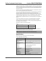
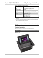
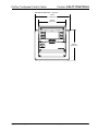
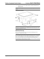
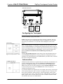
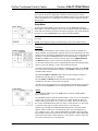
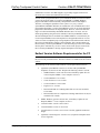
Crestron C2N-FT-TPS4/TPS4-U FlipTop Touchpanel Control Center Operations & Installation Guide This document was prepared and written by the Technical Documentation department at: Crestron Electronics, Inc. 15 Volvo Drive Rockleigh, NJ 07647 1-888-CRESTRON All brand names, product names and trademarks are the property of their respective owners. ©2005 Crestron Electronics, Inc. Crestron C2N-FT-TPS4/TPS4-U FlipTop Control Center Contents FlipTop Touchpanel Control Center: C2N-FT-TPS4/TPS4-U 1 Introduction ..........................................................................................................1 Features and Functions...........................................................................1 Specifications .........................................................................................2 Physical Description...............................................................................3 Industry Compliance ..............................................................................7 Setup.....................................................................................................................8 Network Wiring .....................................................................................8 Crestron Toolbox ...................................................................................9 Identity Code..........................................................................................9 Installation............................................................................................11 Hardware Hookup ................................................................................14 Configuring the Touchpanel.................................................................15 Programming Software.......................................................................................17 Earliest Version Software Requirements for the PC ............................18 Programming with SystemBuilder .......................................................19 Programming with SIMPL Windows...................................................19 Example Program.................................................................................21 Programming with VT Pro-e................................................................21 Uploading and Upgrading ..................................................................................22 Communication Settings ......................................................................22 Uploading a SIMPL Windows Program ..............................................24 Firmware Upgrade ...............................................................................26 Problem Solving .................................................................................................28 Further Inquiries...................................................................................28 Future Updates .....................................................................................28 Software License Agreement..............................................................................29 Return and Warranty Policies.............................................................................31 Merchandise Returns / Repair Service .................................................31 CRESTRON Limited Warranty ...........................................................31 Operations & Installation Guide – DOC. 6398 Contents • i Crestron C2N-FT-TPS4/TPS4-U FlipTop Control Center FlipTop Touchpanel Control Center: C2N-FT-TPS4/TPS4-U Introduction Features and Functions The C2N-FT-TPS4 and C2N-FT-TPS4-U FlipTop Touchpanel control centers (TPS4) comprise a touchpanel housed in a flip top mechanical enclosure. The only difference between the units is that the TPS4-U (universal) does not contain an AC power outlet. All references to TPS4 apply to both units unless specified otherwise. The TPS4 touchpanel is a compact Crestron 3.6-inch touchpanel that provides user interface to a Crestron® remote control system (Cresnet® system). Functional Summary • Stylish FlipTop housing • Integrated 3.6 in (9.15 cm) active matrix color display • 16-bit Isys graphics • 320x240 screen resolution • Synapse image rendering algorithm • 10 translucent white backlit pushbuttons* • WAV file audio feedback • Easy pull-out universal cable management • AC power outlet (C2N-FT-TPS4 only) • Cresnet and Ethernet communications • 8 MB of flash (approx. 7MB for user display lists) • 16 MB of DRAM (Dynamic RAM) for panel firmware * As an option, a custom-engraved bezel can be designed and obtained by using the Crestron Engraver software. Version 2.4 and Crestron Database 17.4 or later are available from the Crestron website (www.crestron.com). The bright, 3.6" active-matrix color touchscreen provides a fully customizable user interface for control of AV, lighting, screens, volume and more. With 16-bit Isys Operations & Installation Guide – DOC. 6398 FlipTop Touchpanel Control Center: C2N-FT-TPS4/TPS4-U • 1 FlipTop Touchpanel Control Center Crestron C2N-FT-TPS4/TPS4-U graphics, the TPS4 produces astounding 3D graphics, dynamic text, and full-motion animations complete with WAV file audio feedback. Ten programmable pushbuttons are also included featuring translucent buttons with white LED backlighting and an engravable faceplate. The units support both Cresnet and Ethernet protocols for communication with other devices as well as uploading programs and firmware. An AC power passthrough is provided with the C2N-FT-TPS4 unit only. Both units provide for extensive connectivity through an easy pull-out cable storage mechanism. Eight grommeted holes are provided in the bottom plate, allowing for smooth pass-thru of virtually any type of AV, communication, control, or data cable (cables not included). When not in use, the user end of each cable stows neatly within the FlipTop compartment while excess cable simply drops out-of-sight below the box. To prevent any inadvertent screen presses, the TPS4 disengages the touchpanel whenever the lid is not fully opened. The TPS4 mounts flush to any tabletop, concealing all cables and connectors, providing a clean professional appearance to any conference room or classroom. The TPS4 is available in four different models. Models MODEL NUMBER COLOR C2N-FT-TPS4-B/C2N-FT-TPS4-U-B Black C2N-FT-TPS4/C2N-FT-TPS4-U-BALUM Brushed Aluminum For simplicity within this guide, the TPS4-U designation and the color suffix are omitted and C2N-FT-TPS4 is used except where noted. NOTE: The TPS4 is compatible with 2-Series control systems only. Specifications Specifications for the TPS4 are given in the following table. C2N-FT-TPS4/TPS4-U Specifications SPECIFICATION DETAILS Cresnet Power Usage 5 Watts (0.21 Amp @ 24 VDC) Default Network ID 03 Firmware tps4_qm-ftcc-tps-tps4_c2n-ft-tps4_2.007.0161.csf or later 2-Series Control System 1,2 Update Files Version 3.137.CUZ or later Connectors LAN (1) 8-Wire RJ-45 with 2 LED indicators Cresnet (2) 4-pin terminal blocks Ground (1) Ground Terminal Touchpanel Display Display Type Size Resolution Colors Illumination Contrast ratio Viewing angle Touchscreen Active matrix color LCD 3.6 in (9.1 cm) 320 x 240 pixels maximum 64,000 (16 bits) LED 300 cd/m² 300:1 typical ±80° typical horizontal, +80°/-50° typical vertical Resistive membrane Continued on next page 2 • FlipTop Touchpanel Control Center: C2N-FT-TPS4/TPS4-U Operations & Installation Guide - DOC. 6398 Crestron C2N-FT-TPS4/TPS4-U FlipTop Touchpanel Control Center C2N-FT-TPS4/TPS4-U Specifications (continued) SPECIFICATION DETAILS Touchpanel Processor CPU Processing Speed 32-bit Freescale Coldfire Microprocessor 96 MIPS Touchpanel Memory 8MB internal flash; 16MB DRAM Touchpanel Ethernet Support 10/100Base-T Full duplex, Link and Activity LEDs Operating Temperature and Humidity 41º to 104º F (5º to 40º C) 10 to 90% relative humidity (non-condensing) Dimensions and Weight Width: 7.67 in (19.49 cm) Height: 5.67 in (14.40 cm) Depth: 6.55 in (16.64 cm) Weight: 4.05 lbs (1.84 kg) 1. The latest software versions can be obtained from the Crestron website. Refer to the NOTE following these footnotes. 2. Crestron 2-Series control systems include the AV2 and PRO2. Consult the latest Crestron Product Catalog for a complete list of 2-Series control systems. NOTE: Crestron software and any files on the website are for Authorized Crestron dealers and Crestron Authorized Independent Programmers (CAIP) only. New users may be required to register to obtain access to certain areas of the site (including the FTP site). Physical Description Refer to the physical views shown below and on subsequent pages. NOTE: The AC outlet and line cord shown in the views that follow only appear on the C2N-FT-TPS4. TPS4 Open View Operations & Installation Guide – DOC. 6398 FlipTop Touchpanel Control center: C2N-FT-TPS4/TPS4-U • 3 FlipTop Touchpanel Control Center Crestron C2N-FT-TPS4/TPS4-U TPS4 Physical Dimensions – Top View 7.67 in (19.49 cm) 6.00 in (15.24 cm) CONTROL CENTER 6.55 in (16.64 cm) 4 • FlipTop Touchpanel Control Center: C2N-FT-TPS4/TPS4-U Operations & Installation Guide - DOC. 6398 Crestron C2N-FT-TPS4/TPS4-U FlipTop Touchpanel Control Center TPS-4 Physical Dimensions - Front View 6.28 in (15.96 cm) 7.17 in (18.22 cm) TPS4 Bottom View LAN Operations & Installation Guide – DOC. 6398 FlipTop Touchpanel Control center: C2N-FT-TPS4/TPS4-U • 5 FlipTop Touchpanel Control Center Crestron C2N-FT-TPS4/TPS4-U TPS4 Physical Dimensions - Back View 2.75 in (6.99 cm) 0.09 in (0.23 cm) 4.66 in (11.84 cm) 5.67 in (14.40 cm) TPS4 Physical Dimensions - Side View 5.51 in (14.0 cm) 6.05 in (15.37 cm) 6 • FlipTop Touchpanel Control Center: C2N-FT-TPS4/TPS4-U Operations & Installation Guide - DOC. 6398 Crestron C2N-FT-TPS4/TPS4-U FlipTop Touchpanel Control Center Controls and Ports (Top) Buttons The TPS-4 touchpanel has 10 hard buttons; five on each side of the display. The buttons are backlit with white LEDs; brightness is program adjustable. The buttons can be programmed to automate frequently used functions. 125V – 50/60Hz 10A AC Outlet (C2N-FT-TPS4 Only) The 3-prong grounded AC outlet is rated 125 VAC @ 10 Amps, 50 – 60 Hz. Ports (Underside) NET 24 Y Z G NET 24 Y Z G These two 4-pin terminal block connectors are for connection to the Cresnet network. One connector is used to connect to the Cresnet network while the second connector can be used to connect another Cresnet device. Cresnet power to the TPS4 is supplied through either of these connectors. For more information, refer to “Network Wiring” on page 8. LAN Green LED Yellow LED 8 1 An 8-wire RJ-45 connector with two LED indicators (green LED indicates link status, yellow LED indicates Ethernet activity). This connector provides an Ethernet 10baseT /100baseTX, full duplex, TCP/IP, UDP/IP, CIP, DHCP, IEEE 802.3U compliant network connection for the TPS4 touchpanel. LAN Connector Pinout PIN SIGNALS PIN 5 SIGNALS 1 TX + N/C 2 TX - 6 RC - 3 RC+ 7 N/C 4 N/C 8 N/C AC Power (C2N-FT-TPS4 Only) Connect the six-foot (183 cm) grounded AC line cord to supply AC power to the outlet on the topside of the TPS4. Industry Compliance As of the date of manufacture, the TPS4 has been tested and found to comply with specifications for CE marking and standards per EMC and Radiocommunications Compliance Labelling. NOTE: This device complies with part 15 of the FCC rules. Operation is subject to the following two conditions: (1) this device may not cause harmful interference, and (2) this device must accept any interference received, including interference that may cause undesired operation. Operations & Installation Guide – DOC. 6398 FlipTop Touchpanel Control center: C2N-FT-TPS4/TPS4-U • 7 FlipTop Touchpanel Control Center Crestron C2N-FT-TPS4/TPS4-U Setup Network Wiring CAUTION: In order to ensure optimum performance over the full range of your installation topology, Crestron Certified Wire, and only Crestron Certified Wire, may be used. Failure to do so may incur additional charges if support is required to identify performance deficiencies as a result of using improper wire. CAUTION: Use only Crestron power supplies for Crestron equipment. Failure to do so could cause equipment damage or void the Crestron warranty. CAUTION: Provide sufficient power to the system. Insufficient power can lead to unpredictable results or damage to the equipment. Please use the Crestron Power Calculator to help calculate how much power is needed for the system (http://www.crestron.com/calculators). When calculating the length of wire for a particular Cresnet run, the wire gauge and the Cresnet power usage of each network unit to be connected must be taken into consideration. Use Crestron Certified Wire only. If Cresnet units are to be daisychained on the run, the Cresnet power usage of each network unit to be daisychained must be added together to determine the Cresnet power usage of the entire chain. If the unit is a home-run from a Crestron system power supply network port, the Cresnet power usage of that unit is the Cresnet power usage of the entire run. The wire gauge and the Cresnet power usage of the run should be used in the following equation to calculate the cable length value on the equation’s left side. Cable Length Equation L< 40,000 RxP Where: L = Length of run (or chain) in feet. 2 R = 6 Ohms (Crestron Certified Wire: 18 AWG (0.75 MM )) P = Cresnet power usage of entire run (or chain). Make sure the cable length value is less than the value calculated on the right side of the equation. For example, a Cresnet run drawing 20 watts should not have a length of run more than 333 feet. NOTE: All Crestron certified Cresnet wiring must consist of two twisted pairs. One twisted pair is the +24V conductor and the GND conductor, and the other twisted pair is the Y conductor and the Z conductor. NOTE: When daisy-chaining Cresnet units, strip the ends of the wires carefully to avoid nicking the conductors. Twist together the ends of the wires that share a pin on the network connector, and tin the twisted connection. Apply solder only to the ends of the twisted wires. Avoid tinning too far up the wires or the end becomes brittle. Insert the tinned connection into the Cresnet connector and tighten the retaining screw. Repeat the procedure for the other three conductors. NOTE: For larger networks (i.e., greater than 28 network devices), it may become necessary to add a Cresnet Hub/Repeater (CNXHUB) to maintain signal quality throughout the network. Also, for networks with lengthy cable runs, it may be necessary to add a Hub/Repeater after only 20 devices. 8 • FlipTop Touchpanel Control Center: C2N-FT-TPS4/TPS4-U Operations & Installation Guide - DOC. 6398 Crestron C2N-FT-TPS4/TPS4-U FlipTop Touchpanel Control Center Crestron Toolbox The Crestron Toolbox (replacement for Crestron Viewport) is a broad-based software package that accomplishes multiple system tasks, primarily using an RS-232 or TCP/IP connection between a PC and one or more Crestron control systems. You can use the Crestron Toolbox to: • Observe system processes. • Upload operating systems and firmware. • Upload programs and touchpanel projects. • Set or change device Network IDs. • Change serial numbers. • Run scripts to automate tasks. • Perform system diagnostics, and much more. The Crestron Toolbox allows you to perform these functions using simple graphical views and click and drag methods. Identity Code Every piece of equipment and user interface within the network requires a unique identity code (Net ID). These codes are two-digit hexadecimal numbers from 03 to FE (Net ID 02 is reserved for master control units). The Net IDs reside within all Cresnet devices (hardware) and must match the Net ID as specified in the software (SIMPL Windows) that runs the system. Refer to “Setting the Net ID in Device Settings” on page 20 for details of the SIMPL Windows procedure. The Net ID of the TPS4 has been factory set to 03. The Net IDs of multiple TPS4s in the same system must be unique. Net IDs can be changed from a personal computer (PC) using SystemBuilder™ or Crestron Toolbox, or through the device SETUP MENU as described on page 16. NOTE: For detailed information on establishing communication between the PC and control system, refer to “Communication Settings” on page 22. If communication cannot be established, refer to the “Troubleshooting Communications” section in the latest version of the 2-Series Control System Reference Guide (Doc. 6256), which is available from the Crestron website (http://www.crestron.com/manuals). The Crestron Toolbox provides several methods to easily set or change device Net IDs for any device on the network. The following method permits you to change the Net ID of any device in the network through the “Network Device Tree” window. NOTE: This method prevents you from setting duplicate IDs. This method permits you to manually set the Net ID for any device in the network, can be used to set any known Net IDs that may require changing, and may also be used for non-TSID equipment. This method will not permit you to choose an ID already in use by another device. A warning message will appear if you attempt to use an ID that is already in use. Operations & Installation Guide – DOC. 6398 FlipTop Touchpanel Control center: C2N-FT-TPS4/TPS4-U • 9 FlipTop Touchpanel Control Center Crestron C2N-FT-TPS4/TPS4-U Duplicate Net ID Warning Message This method does not change the Net ID as assigned in SIMPL windows. Refer to page 20 for the SIMPL Windows ID change procedure. NOTE: You may also use SystemBuilder to perform Network ID setup. 1. Ensure that all network devices are connected to the control system. 2. Open Crestron Toolbox and establish communications (refer to page 22). 3. icon, or select Tools | Network Select the Network Device Tree Device Tree. (Refer to the following figure.) Network Device Tree 4. Click on the ‘+’ next to the name of the device to display its current Net ID setting, and then right-click on the Net ID you wish to change. When the sub-menu appears, select Change Network ID from the sub-menu. Network Device Tree – Sub-Menu 5. The current Net ID is highlighted. Enter a new Net ID and press Enter. Enter New Net ID 10 • FlipTop Touchpanel Control Center: C2N-FT-TPS4/TPS4-U Operations & Installation Guide - DOC. 6398 Crestron C2N-FT-TPS4/TPS4-U FlipTop Touchpanel Control Center 6. An alert message appears to notify you that the change was successful. 7. Repeat this procedure for each network device requiring a Net ID change. Installation Physical installation of the TPS4 includes installing an engraved touchpanel bezel, installation of the supplied cable management plate, and mounting the unit to the desired surface. Installing Engraved Bezel Use the Crestron Engraver software package to obtain a custom-engraved bezel for the TPS4. Install the replacement bezel as follows. A 1/16” Allen (hexhead) wrench is required for this procedure. 1. Remove and retain the four #4 buttonhead screws securing the bezel to the flip-top cover. (Refer to the following illustration.) 2. Carefully lift the bezel from the unit. 3. Place the engraved bezel in position on the unit and attach it using the four screws removed in step one. Engraved Bezel Installation #4 Buttonhead Screws Cable Management Plate The TPS4 is shipped with a cable management plate and associated parts to provide a pullout cable solution for up to eight AV, communication, control, or data cables (cables not included). The parts include an eight-hole plate and grommets (bushings). Refer to the following table. Operations & Installation Guide – DOC. 6398 FlipTop Touchpanel Control center: C2N-FT-TPS4/TPS4-U • 11 FlipTop Touchpanel Control Center Crestron C2N-FT-TPS4/TPS4-U Parts Supplied for the Optional Cable Management Plate PART DESCRIPTION QUANTITY Small Cable Bushing, 5/16 inch ID, 0.5 inch OD 4 Medium Cable Bushing, 0.39 inch ID, 0.64 inch OD 2 Large cable Bushing, 0.55 inch ID, 0.80 inch OD 2 Cable Support Plate 1 Screws, 4-40 x ¼ , black, Phillips head 4 The only tool required for installation of the cable support plate is a Phillips screwdriver. The cable support plate must be installed before mounting the TPS4 to a surface. The cables are looped through the cable support plate. 1. Place the bushings on the cables (eight bushings supplied). Use the large bushing for the VGA cable. 2. Thread the cables through the appropriate slot on the plate. 3. Snap the bushings into the plate slots. 4. Feed all the excess cable through the opening. 5. Attach the plate using the four 4-40 x ¼ screws supplied. Cable Management Plate Installation Bushings Cable Support Plate (4) #4 x 1/4 LG Black Screws Mounting to Surface The TPS4 is designed to mount in a horizontal surface, such as a desk top, lectern, or podium. The following diagram illustrates the required opening size to accommodate the TPS4. A cutout template (4007478) is included. 12 • FlipTop Touchpanel Control Center: C2N-FT-TPS4/TPS4-U Operations & Installation Guide - DOC. 6398 Crestron C2N-FT-TPS4/TPS4-U FlipTop Touchpanel Control Center Cutout Dimensions TPS4 (4007478) 7.25 in (18.42 cm) 6.13 in (15.56 cm) Max Radius (0.125 in) (0.32 cm) NOTE: Before inserting the TPS4 in the mounting hole, ensure that all required cables have been installed. Mounting Parts Supplied with the TPS4 PART DESCRIPTION Screw #6-32, Pan Head, Phillips QUANTITY 8 Screw #10, Pan Head, Phillips 4 Mounting Bracket 2 1. Install the eight supplied #6-32 screws, but do not tighten (four on the front side and four on the rear side). These will be used to secure the front and rear mounting brackets. 2. Position the TPS4 in the mounting hole. (Refer to the following graphic.) Mounting Bracket Screw Locations 3. Install the four #10 screws in the mounting brackets (two screws per bracket). Refer to the following diagram. 4. Slide the mounting brackets over the #6-32 screws and tighten the #6-32 screws. Operations & Installation Guide – DOC. 6398 FlipTop Touchpanel Control center: C2N-FT-TPS4/TPS4-U • 13 FlipTop Touchpanel Control Center 5. Crestron C2N-FT-TPS4/TPS4-U Turn the four #10 screws equally until they contact the underside of the mounting surface. NOTE: Do not over-tighten the #10 screws as this may damage the surface and/or the unit. Mounting Bracket Installation NOTE: Be careful not to press any screen pushbuttons or hard keys while closing the Flip Top, even though the screen is disabled when the Flip Top begins to close and all pressed buttons are released. Hardware Hookup Refer to the following hookup diagram and, aside from attaching power last, complete the connections in any order. NOTE: To prevent overheating, do not operate this product in an area that exceeds the environmental temperature range listed in the specifications table. Consideration must be given if installed in a closed or multi-unit rack assembly, inside a closed desk, or in a closed podium since the operating ambient temperature of these environments may be greater than the room ambient. Contact with thermal insulating materials should be avoided on all sides of the unit. 14 • FlipTop Touchpanel Control Center: C2N-FT-TPS4/TPS4-U Operations & Installation Guide - DOC. 6398 Crestron C2N-FT-TPS4/TPS4-U FlipTop Touchpanel Control Center Underside Connections GROUND LAN 120 VAC LINE CORD (C2N-FT-TPS4 ONLY) CRESNET: TO CONTROL SYSTEM AND OTHER CRESNET DEVICES ETHERNET: 10/100 BASE-T ETHERNET TO LAN Configuring the Touchpanel NOTE: The only connection required to configure the touchpanel is power. Refer to “Hardware Hookup” on page 14 for details. MAIN MENU NOTE: The touch screen responds to both finger and stylus commands. Since the screen is small, Crestron recommends that a stylus (not supplied) be used to ensure the accuracy of commands. Use a stylus that will not damage the surface of the screen. Prior to normal operation, it is advisable to configure the unit using a series of setup screens. The MAIN MENU for configuring the touchpanel appears when a finger (or stylus) is held (approximately five seconds) to the touchscreen when power is applied. Upon entering SETUP MODE, the MAIN MENU, shown to the left, displays four buttons: Touch Screen Calibration, Exit and Run Program, Setup, and Diagnostics. This menu can also be obtained via digital reserved join number, 17242. Selecting Exit and Run Program verifies that all of the setup information has been saved to EEPROM and displays the main page that has been programmed into the touchpanel. The remaining buttons on the MAIN MENU open other menus, which are discussed in subsequent paragraphs. Calibration Menu CALIBRATION MENU Calibration of the touchscreen is required if the active touch area of a button does not coincide with the button's image. Select the Touch Screen Calibration button to display the CALIBRATION MENU, as shown to the left. The CALIBRATION MENU offers the choice to initiate calibration with the Perform Calibration button or return to the previous screen with the Return button. Choose an option by touching the appropriate button. If you need to calibrate the touchpanel, the screen displays the message "Touch Upper Left" centered on the panel with a cross hair in the upper left corner. Touch the cross hair to initiate calibration. Another message, "Touch Upper Right", appears with a cross hair in the correct corner. Touch the cross hair. A final message, “Touch Lower Right”, appears with a cross hair in the correct corner. Touch the crosshair to finish the calibration and return to the MAIN MENU. Operations & Installation Guide – DOC. 6398 FlipTop Touchpanel Control center: C2N-FT-TPS4/TPS4-U • 15 FlipTop Touchpanel Control Center Crestron C2N-FT-TPS4/TPS4-U NOTE: When touching each crosshair during calibration, be as accurate as possible. Use a stylus or the tip of a capped pen or the eraser end of a pencil. To cancel calibration and return to the CALIBRATION MENU without saving calibration data, create a calibration error by touching the screen in an area that is opposite from the instructed area. Setup Menu SETUP MENU To obtain the SETUP MENU, shown to the left, press the Setup button from the MAIN MENU. The SETUP MENU offers a series of buttons, which open additional menus and screens that are detailed in subsequent paragraphs. After setup parameters have been set, select the Return button to return to the MAIN MENU. NOTE: For convenience, the current CRESNET ID setting is displayed in the lower left corner. NOTE: All touchpanel settings are automatically saved in non-volatile memory. Interface INTERFACE MENU The touchpanel communicates with a control system to activate commands or to display feedback from components within the system. The communication interface must be correctly specified or communication will not occur. To set communication parameters, first select the Interface button on the SETUP MENU to display the INTERFACE MENU screen, shown to the left. Then, use the CRESNET ID UP and DOWN buttons to set the Cresnet network identity (CRESNET ID). Use the other buttons on the screen to enable/disable the preferred communications protocol: Cresnet II, Ethernet, or CIP (Crestron Internet Protocol). Cresnet II buttons determine the touchpanel’s communication mode. Select Enable for normal Cresnet communications (default); select Disable to disable the Cresnet communications interface. The Ethernet Enable and Disable buttons determine the touchpanel’s ability to communicate with other devices via Ethernet. The CIP Enable and Disable buttons determine the touchpanel’s ability to communicate with other Crestron devices using CIP. After the Cresnet ID setting has been verified and the communications protocol has been selected, press Return to save the settings and return to the SETUP MENU. AUDIO MENU Audio From the SETUP MENU, press the Audio button to open the AUDIO MENU screen, shown at left. Press the WAV button to open the AUDIO SETUP – WAV screen. Use the buttons on this screen to set the WAV file volume level, to enable/disable the WAV file function and to play the WAV file to verify your settings. The area to the right of the volume UP/DOWN buttons shows the relative volume from 0% to 100%, both as a numeric value and, for a quick visual reference, as an analog bar. Similarly, press the KEY CLICK Enabled/Disabled button to open the AUDIO SETUP – KEY CLICK screen. Use the buttons on this screen to adjust the key click volume level (0 – 100%), and to enable/disable an audible tone (beep) when the touchpanel buttons are pressed. The area to the right of the volume UP/DOWN buttons shows the relative volume from 0% to 100%, both as a numeric value and, for a quick visual reference, as an analog bar. 16 • FlipTop Touchpanel Control Center: C2N-FT-TPS4/TPS4-U Operations & Installation Guide - DOC. 6398 Crestron C2N-FT-TPS4/TPS4-U FlipTop Touchpanel Control Center Press the Restore Default Audio Settings button to cancel any changes and restore all default audio settings: WAV volume = 100%, and WAV function enabled; key click volume = 100%, and key click function enabled. Press Return to save the settings and return to the SETUP MENU. Screen Settings SCREEN SETTINGS From the SETUP MENU, press the Screen Settings button to open the SCREEN SETTINGS screen, shown at left. Press the Brightness button to open the SCREEN SETTINGS – BRIGHTNESS screen. Use the UP/DOWN buttons to set the display brightness (0 – 100%). The area to the right of the buttons shows the relative brightness from 0% to 100%, both as a numeric value and, for quick visual reference, as an analog bar. Press the Key Backlight button to open the SCREEN SETTINGS – KEY BACKLIGHT screen. Use the UP/DOWN buttons to set the key backlight brightness (0 – 100%). The area to the right of the buttons shows the relative brightness from 0% to 100%, both as a numeric value and, for quick visual reference, as an analog bar. Press the LCD Bias button to open the SCREEN SETTINGS – LCD BIAS screen. Use the UP/DOWN buttons to set the LCD bias (0 – 255). Use the graphic on the right side of the screen to see the effects of the adjustment. The bias setting is best when the lines are crisp and dark and the white area around them is bright. Press Return to save the settings and return to the SETUP MENU. Timeout Settings TIMEOUT SETTINGS From the SETUP MENU, press the Timeout button to open the SCREEN SETTINGS – TIMEOUT screen. Use the UP/DOWN buttons to set the timeout from 0 through 120 minutes, where 0 disables the timeout. Adjustment is in oneminute increments from 1 to 10; in ten-minute increments from 20-120. STANDBY timeout turns the display and backlight off when the touchpanel is inactive for the specified time. When the touchpanel is reactivated, the last screen to be displayed reappears. The specified time is displayed in minutes. The default STANDBY timeout is 10 minutes. Press Return to save the settings and return to the SETUP MENU. Diagnostics Menu DIAGNOSTICS MENU The Diagnostics button from the MAIN MENU should only be used under supervision from a Crestron customer service representative during telephone support. Many options available from the DIAGNOSTICS MENU, shown to the left, are numeric in nature and their interpretation is beyond the scope of this manual. Programming Software Have a question or comment about Crestron software? Answers to frequently asked questions (FAQs) can be viewed in the Online Help section of the Crestron website. To post a question or view questions you have Operations & Installation Guide – DOC. 6398 FlipTop Touchpanel Control center: C2N-FT-TPS4/TPS4-U • 17 FlipTop Touchpanel Control Center Crestron C2N-FT-TPS4/TPS4-U submitted to Crestron’s True Blue Support, log in at http://support.crestron.com. First-time users will need to establish a user account. You can create a program that allows you to include the TPS4 in a Crestron control system. The program output of Crestron SystemBuilder is a SIMPL Windows program with much of the functionality encapsulated in macros and templates. Therefore, extending the capabilities of the system is very easy. Crestron SystemBuilder and SIMPL Windows are intended for users with different levels of programming knowledge. Crestron SystemBuilder is easier to use for the beginning programmer, and much faster for all programmers. However, it does not allow the degree of control and flexibility that SIMPL Windows does. Of course, one can initiate programming using the easiest method (Crestron SystemBuilder) and use advanced techniques that are available from SIMPL Windows to customize the job. Crestron SystemBuilder comes with templates for all supported interfaces. If a user wishes to create a touchpanel project using templates with a different look-and-feel, this can be accomplished by making a custom template. This custom template can then be used by Crestron SystemBuilder to create the final project files to be loaded into the panels. Alternatively, VT Pro-e can be used to tweak projects created with the Crestron SystemBuilder or develop original touchpanel screen designs. Earliest Version Software Requirements for the PC NOTE: Crestron recommends that you use the latest software to take advantage of the most recently released features. The latest software is available from the Crestron website. The following are the earliest useable software version requirements for the PC: • (Optional) System Builder version 2.0.6 or later with SystemBuilder Templates version 2.0.1or later. Requires the following software versions: o SIMPL Windows version 2.06.20 or later with library update file 345 or later. Requires SIMPL+ Cross Compiler version 1.1. o Crestron database 17.4.0 or later o Vision Tools Pro-e 3.3.4.0 or later o Crestron Toolbox 1.01.06 or later o Engraver 2.4.1.2 or later o Microsoft DCOM '98 if running under Win 95 or 98 (not needed for NT or 2000) o Microsoft Data Access Components if running under Win 95 or 98 (not needed for NT or 2000) • SIMPL Windows version 2.06.20 or later, with Library Update file 355. Requires SIMPL+® Cross Compiler version 1.1. • Crestron Toolbox version 1.02.05 or later. • Crestron Database version 17.4.0 or later. • VisionTools Pro-e version 3.4.2.5 or later. Used for graphical touchscreen design. • (Optional) Crestron Engraver version 2.6.0.0. (required if touchpanel bezel is to be engraved). 18 • FlipTop Touchpanel Control Center: C2N-FT-TPS4/TPS4-U Operations & Installation Guide - DOC. 6398 Crestron C2N-FT-TPS4/TPS4-U FlipTop Touchpanel Control Center Programming with SystemBuilder The easiest method of programming, but does not offer as much flexibility as SIMPL Windows. Crestron SystemBuilder offers automatic programming for such residential and commercial applications as audio distribution, home theater, video conferencing, and lighting. The interface of this tool guides you through a few basic steps for designating rooms and specifying the control system, touchpanels, devices, and functionality. Crestron System Builder then programs the system, including all touchpanel projects and control system logic. Crestron SystemBuilder is fully integrated with Crestron's suite of software development tools, including SIMPL Windows, VT Pro-e, Crestron Database, User IR Database, and User Modules Directory. Crestron System Builder accesses these tools behind the scenes, enabling you to easily create robust systems. NOTE: Modifications to the program that are made outside of SystemBuilder (for example, in VT Pro-e or SIMPL Windows) are not preserved when you reenter SystemBuilder. Programming with SIMPL Windows NOTE: The following assumes that the reader has knowledge of SIMPL Windows. If not, refer to the extensive help information provided with the software. NOTE: The following are acceptable file extensions for programs that include a TPS4, developed for specific control system types: .smw projectname.smw (source file) .spz projectname.spz (compiled file for 2-Series) .usp projectname.usp (source code module for SIMPL+) .ir projectname.ir (user IR) .umc projectname.umc (user macro) .ush projectname.ush (completed SIMPL+) NOTE: In the following description, the PRO2 control system is used. SIMPL Windows is Crestron's software for programming Crestron control systems. It provides a well-designed graphical environment with a number of workspaces (i.e., windows) in which a programmer can select, configure, program, test, and monitor a Crestron control system. SIMPL Windows offers drag and drop functionality in a familiar Windows environment. This section explains how to create a SIMPL Windows program that includes a TPS4 within a Cresnet system. Configuration Manager is where programmers “build” a Crestron control system by selecting hardware from the Device Library. In Configuration Manager, drag the PRO2 from the Control Systems folder of the Device Library and drop it in the upper pane of the System Views. The PRO2 with its associated communication ports is displayed in the System Views upper pane. NOTE: The information in this section assumes that the reader has knowledge of SIMPL Windows. If not, refer to the extensive help information provided with the software. In Configuration Manager, drag the PRO2 from the Control Systems folder of the Device Library to System Views. Operations & Installation Guide – DOC. 6398 FlipTop Touchpanel Control center: C2N-FT-TPS4/TPS4-U • 19 FlipTop Touchpanel Control Center Crestron C2N-FT-TPS4/TPS4-U System View of PRO2 The System Views lower pane displays the PRO2 system tree. This tree can be expanded to display and configure the communications ports. Expanded PRO2 System Tree C2Net-Device Slot in Configuration Manager To incorporate a TPS4 into the system, drag the C2N-FT-TPS-4 (Cresnet) from the Touchpanels | Touchpanels (Cresnet) folder of the Device Library and drop it in System Views. The PRO2 system tree displays the TPS4 in Slot 9, with a default Net ID of 03, as shown in the following illustration. C2Net Device, Slot 9 NOTE: Alternatively, the TPS4 touchpanel could be connected to the control system via Ethernet instead of Cresnet. Setting the Net ID in Device Settings Double-click the C2N-FT-TPS4 (Cresnet) icon in the upper pane to open the “Device Settings” window. This window displays TPS4 device information. The Net ID can be changed in this window using the Net ID tab, as shown in the following figure. 20 • FlipTop Touchpanel Control Center: C2N-FT-TPS4/TPS4-U Operations & Installation Guide - DOC. 6398 Crestron C2N-FT-TPS4/TPS4-U FlipTop Touchpanel Control Center “Device Settings” Window NOTE: This procedure sets the Net ID for the TPS4 in the program only. It does not automatically set the Net ID for the C2N-FT-TPS4/TPS4-U hardware. SIMPL Windows automatically changes Net ID values of a device added to a program if a duplicate device or a device with the same Net ID already exists in the program. Always ensure that the hardware and software settings of the Net ID match. For Net ID hardware setting details, refer to “Identity Code” on page 9. Symbols in Programming Manager Programming Manager is where programmers “program” a Creston control system by assigning signals to symbols. The symbol for the C2N-TPS-TPS4 (Cresnet) can be viewed by double-clicking on the icons or dragging them into Detail View. A description for each signal in the symbol is provided in the SIMPL Windows help file (F1). Device Extender If you wish to have the program sense the open and closed position of the flip top, insert the Flip Top Open/Close device extender. Example Program An example program for the C2N-FT-TPS4/TPS4-U is available from the “Example Program” section of the Crestron website (www.crestron.com/exampleprograms). Search for C2N-FT-TPS4/TPS4-U.ZIP. Programming with VT Pro-e VT Pro-e, design and programming Windows-based software, permits the creation of unlimited control screen variations incorporating two and three-dimensional graphics and text. A set of pages, which make up a project, can be designed for each TPS4 touchpanel application. Each page contains objects such as custom control graphics, two and three-dimensional buttons, sliders, and digital readouts which allow the user to interface with the control system via join numbers. Unjoined objects are not interfaced with the system and thus cannot initiate any functions. The completed and compiled project is uploaded to the touchpanel and programmed into the flash PROM via the File | Upload Project command. The touchpanel uses the Operations & Installation Guide – DOC. 6398 FlipTop Touchpanel Control center: C2N-FT-TPS4/TPS4-U • 21 FlipTop Touchpanel Control Center Crestron C2N-FT-TPS4/TPS4-U programmed project until another set is uploaded from the PC. The PC may be disconnected from the control system or panel except during reprogramming. When you start the VT Pro-e project for this product, select C2N-FT-TPS4 as the panel type. For additional software information, refer to the help file provided with the software. The latest version of VT Pro-e can be obtained from the Crestron website. Uploading and Upgrading NOTE: Crestron recommends using the latest programming software and that each device contains the latest firmware to take advantage of the most recently released features. Please check the Crestron website (http://www.crestron.com/updates) for the latest versions of software and firmware. New users are required to register to obtain access to this site. Assuming a PC is properly connected to the entire system, Crestron programming software allows the programmer to upload programs and projects to the system and touchpanel and firmware to the wall plates after their development. However, there are times when the files for the program and projects are compiled and not uploaded. Instead, compiled files may be distributed from programmers to installers, from Crestron to dealers, etc. Even firmware upgrades are available from the Crestron website as new features are developed after product releases. In those instances, one has the option to upload via the programming software or to upload and upgrade via the Crestron Toolbox. The following sections define how one would upload a SIMPL Windows program to the control system, or upgrade the firmware of the C2N-FT-TPS4/TPS4-U. However, before attempting to upload or upgrade, it is necessary to establish communications. Communication Settings NOTE: For laptops and other PCs without a built-in RS-232 port, Crestron recommends the use of a PCMCIA card over a USB adapter, particularly if using Viewport. Establishing communications is an essential step when setting up the control system. Once communications are established with the control system, you can upload programming, update firmware, and use all the diagnostic tools available in Crestron Toolbox. Communications can be established using a serial (RS-323) connection, or by using a TCP/IP connection. For additional connection details, refer to “Establishing Communications with the Control System” in the latest version of the 2-Series Control Systems Reference Guide, Doc. 6256. The procedure in this section provides details for RS-232 communication between the PC and the control system. If TCP/IP communication is preferred, consult the latest version of the Crestron e-Control Reference Guide (Doc. 6052) or the respective Operations Guide for the control system. These documents are available from the Crestron website. Refer to the following figure for a typical connection diagram when uploading files. 22 • FlipTop Touchpanel Control Center: C2N-FT-TPS4/TPS4-U Operations & Installation Guide - DOC. 6398 Crestron C2N-FT-TPS4/TPS4-U FlipTop Touchpanel Control Center Typical Connection Diagram when Uploading NOTE: Use a straight-through serial cable for connection to a 2-Series processor. 1. Open Crestron Toolbox and click Tools | Manage Address Book to display the communications settings. The DefaultAddressBook.adr file contains several default address settings. Select Serial on COM 1 for serial communication. Crestron Toolbox – “Address Book” Window The PC communication settings specified in the address book should match the protocol that the control processor expects. The settings are as follows: Operations & Installation Guide – DOC. 6398 • Port = COM 1 through COM 8. Select the correct COM port on the PC. • Baud rate = Auto Detect. • Parity = None. • Number of data bits = 8. • Number of stop bits = 1. • Hardware handshaking (RTS/CTS) enabled. • Software handshaking (XON/XOFF) not enabled. FlipTop Touchpanel Control center: C2N-FT-TPS4/TPS4-U • 23 FlipTop Touchpanel Control Center Crestron C2N-FT-TPS4/TPS4-U 2. After setting the correct parameters, click OK to return to the Crestron Toolbox main window. 3. Select Tools | System Info. If the connection is successful, the System Info window displays the processor and device information. System Info Window NOTE: To enter the console mode, click the console mode icon . Uploading a SIMPL Windows Program A control system source file has the extension .smw. A compiled SIMPL Windows file has the extension .spz for a 2-Series control system. The SIMPL Windows file can be uploaded to the control system using SIMPL Windows or via the Crestron Toolbox. Upload via SIMPL Windows 1. Start SIMPL Windows. 2. Select File | Open to view the “Open” window, navigate to the SIMPL Window file (.smw), and click Open. 3. Select Project | Transfer Program. Upload via Crestron Toolbox 1. Verify that the procedure for “Communication Settings” that begins on page 22 has been performed. 24 • FlipTop Touchpanel Control Center: C2N-FT-TPS4/TPS4-U Operations & Installation Guide - DOC. 6398 Crestron C2N-FT-TPS4/TPS4-U FlipTop Touchpanel Control Center 2. Once communication is established, the Functions menu becomes available. 3. Select Functions | SIMPL Program…The “SIMPL Program” window appears, as shown in the following figure, and permits you to browse for a compiled program file (.spz), and to upload it to internal flash. “SIMPL Program” Window 4. Browse for the appropriate .spz file in the “Open” window, and click Open. “Open” Window 5. When the “SIMPL Program” window reappears, click Send. 6. To verify that the program has been transferred successfully, select Functions | SIMPL Program. Details about the current program loaded in the control system are displayed in the upper left corner of the “SIMPL Program” window. Operations & Installation Guide – DOC. 6398 FlipTop Touchpanel Control center: C2N-FT-TPS4/TPS4-U • 25 FlipTop Touchpanel Control Center Crestron C2N-FT-TPS4/TPS4-U Firmware Upgrade To take advantage of all the C2N-FT-TPS4/TPS4-U features, it is important that the unit contains the latest firmware available. Please check the Crestron website for the latest version of firmware. Not every product has a firmware upgrade, but as Crestron improves functions, adds new features, and extends the capabilities of its products, firmware upgrades are posted. Typically, upgrade files are downloaded as .zip files. With Toolbox, it is not necessary to extract the files before uploading; Toolbox will automatically extract the file(s) for you. To upgrade the firmware, complete the following steps. NOTE: A firmware upgrade file for the TPS4 touchpanel has the extension .csf. The following is a typical firmware upgrade file name for the C2N-FT-TPS4. tps-4_qm-ftcc-tps_tps-4_c2n-ft-tps-4_2.007.0161.csf 1. Make sure that “Communication Settings,” which begins on page 22, has been performed. 2. Open Crestron Toolbox. 3. Open the Network Device Tree (the firmware upgrade function is also available in the SMW Program Tree window). 4. Click on the ‘+’ next to the device name to display the Net ID, then rightclick on the Net ID and select Functions | Firmware. (Refer to the following illustration.) Network Device Tree Window – Right-Click Sub Menu 5. The “Firmware” window displays the model and current firmware version as shown in the following graphic. 26 • FlipTop Touchpanel Control Center: C2N-FT-TPS4/TPS4-U Operations & Installation Guide - DOC. 6398 Crestron C2N-FT-TPS4/TPS4-U FlipTop Touchpanel Control Center “Firmware” Window 6. Click Browse to display the Open window to locate the desired firmware (.zip) file. Locate Firmware in the “Open” Window 7. Highlight the desired .zip file and click Open to select the file and return to the “Firmware” window. Note that Toolbox displays the actual firmware file name, not the name of the .zip file. Click Send to transfer the file. The File Transfer window monitors the transfer of the file and gives you the option of canceling the transfer. “File Transfer” Window Operations & Installation Guide – DOC. 6398 FlipTop Touchpanel Control center: C2N-FT-TPS4/TPS4-U • 27 FlipTop Touchpanel Control Center 8. Crestron C2N-FT-TPS4/TPS4-U When the transfer is complete, the “Firmware” window reopens indicating the new firmware version. Click Close after the firmware has been transferred. NOTE: If problems arise when transferring any Cresnet file (touchpanel project/firmware), lower the port speed baud rate to 38400 to match the Cresnet bus speed. Problem Solving The following table provides corrective action for possible trouble situations. If further assistance is required, please contact a Crestron customer service representative. C2N-FT-TPS4/TPS4-U Troubleshooting TROUBLE C2N-FTTPS4/TPS4-U not functioning. PWR LED does not illuminate. POSSIBLE CAUSE(S) CORRECTIVE ACTION Net ID is not correct. Verify the Net ID In Toolbox. Net ID is not set to match the Net ID specified in SIMPL Windows. Verify SIMPL Windows program for setting Net IDs. Net ID is the same as another device’s Net ID. Assign a different Net ID. Not receiving power. Verify that Cresnet is properly attached. Buttons do not function when pressed. Net ID incorrect or does not In Toolbox, check Functions | CresnetID to verify Net ID. Verify match SIMPL Windows SIMPL Windows program ID. program. Button press yields incorrect result. Incorrect programming. Verify SIMPL Windows program. Further Inquiries If you cannot locate specific information or have questions after reviewing this guide, please take advantage of Crestron's award winning customer service team by calling the Crestron corporate headquarters at 1-888-CRESTRON [1-888-273-7876]. For assistance in your local time zone, refer to the Crestron website (http://www.crestron.com/) for a listing of Crestron worldwide offices. You can also log onto the online help section of the Crestron website to ask questions about Crestron products. First-time users will need to establish a user account to fully benefit from all available features. Future Updates As Crestron improves functions, adds new features, and extends the capabilities of the C2N-FT-TPS4/TPS4-U, additional information may be made available as manual updates. These updates are solely electronic and serve as intermediary supplements prior to the release of a complete technical documentation revision. Check the Crestron website periodically for manual update availability and its relevance. Updates are identified as an “Addendum” in the Download column. 28 • FlipTop Touchpanel Control Center: C2N-FT-TPS4/TPS4-U Operations & Installation Guide - DOC. 6398 Crestron C2N-FT-TPS4/TPS4-U FlipTop Touchpanel Control Center Software License Agreement This License Agreement (“Agreement”) is a legal contract between you (either an individual or a single business entity) and Crestron Electronics, Inc. (“Crestron”) for software referenced in this guide, which includes computer software and, as applicable, associated media, printed materials, and “online” or electronic documentation (the “Software”). BY INSTALLING, COPYING, OR OTHERWISE USING THE SOFTWARE, YOU REPRESENT THAT YOU ARE AN AUTHORIZED DEALER OF CRESTRON PRODUCTS OR A CRESTRON AUTHORIZED INDEPENDENT PROGRAMMER AND YOU AGREE TO BE BOUND BY THE TERMS OF THIS AGREEMENT. IF YOU DO NOT AGREE TO THE TERMS OF THIS AGREEMENT, DO NOT INSTALL OR USE THE SOFTWARE. IF YOU HAVE PAID A FEE FOR THIS LICENSE AND DO NOT ACCEPT THE TERMS OF THIS AGREEMENT, CRESTRON WILL REFUND THE FEE TO YOU PROVIDED YOU (1) CLICK THE DO NOT ACCEPT BUTTON, (2) DO NOT INSTALL THE SOFTWARE AND (3) RETURN ALL SOFTWARE, MEDIA AND OTHER DOCUMENTATION AND MATERIALS PROVIDED WITH THE SOFTWARE TO CRESTRON AT: CRESTRON ELECTRONICS, INC., 15 VOLVO DRIVE, ROCKLEIGH, NEW JERSEY 07647, WITHIN 30 DAYS OF PAYMENT. LICENSE TERMS Crestron hereby grants You and You accept a nonexclusive, nontransferable license to use the Software (a) in machine readable object code together with the related explanatory written materials provided by Crestron (b) on a central processing unit (“CPU”) owned or leased or otherwise controlled exclusively by You, and (c) only as authorized in this Agreement and the related explanatory files and written materials provided by Crestron. If this software requires payment for a license, you may make one backup copy of the Software, provided Your backup copy is not installed or used on any CPU. You may not transfer the rights of this Agreement to a backup copy unless the installed copy of the Software is destroyed or otherwise inoperable and You transfer all rights in the Software. You may not transfer the license granted pursuant to this Agreement or assign this Agreement without the express written consent of Crestron. If this software requires payment for a license, the total number of CPU’s on which all versions of the Software are installed may not exceed one per license fee (1) and no concurrent, server or network use of the Software (including any permitted back-up copies) is permitted, including but not limited to using the Software (a) either directly or through commands, data or instructions from or to another computer (b) for local, campus or wide area network, internet or web hosting services; or (c) pursuant to any rental, sharing or “service bureau” arrangement. The Software is designed as a software development and customization tool. As such Crestron cannot and does not guarantee any results of use of the Software or that the Software will operate error free and You acknowledge that any development that You perform using the Software or Host Application is done entirely at Your own risk. The Software is licensed and not sold. Crestron retains ownership of the Software and all copies of the Software and reserves all rights not expressly granted in writing. OTHER LIMITATIONS You must be an Authorized Dealer of Crestron products or a Crestron Authorized Independent Programmer to install or use the Software. If Your status as a Crestron Authorized Dealer or Crestron Authorized Independent Programmer is terminated, Your license is also terminated. You may not rent, lease, lend, sublicense, distribute or otherwise transfer or assign any interest in or to the Software. You may not reverse engineer, decompile, or disassemble the Software. You agree that the Software will not be shipped, transferred or exported into any country or used in any manner prohibited by the United States Export Administration Act or any other export laws, restrictions or regulations (“Export Laws”). By downloading or installing the Software You (a) are certifying that You are not a national of Cuba, Iran, Iraq, Libya, North Korea, Sudan, or Syria or any country to which the United States embargoes goods (b) are certifying that You are not otherwise prohibited from receiving the Software and (c) You agree to comply with the Export Laws. If any part of this Agreement is found void and unenforceable, it will not affect the validity of the balance of the Agreement, which shall remain valid and enforceable according to its terms. This Agreement may only be modified by a writing signed by an authorized officer of Crestron. Updates may be licensed to You by Crestron with additional or different terms. This is the entire agreement between Crestron and You relating to the Software and it supersedes any prior representations, discussions, undertakings, communications or advertising relating to the Software. The failure of either party to enforce any right or take any action in the event of a breach hereunder shall constitute a waiver unless expressly acknowledged and set forth in writing by the party alleged to have provided such waiver. If You are a business or organization, You agree that upon request from Crestron or its authorized agent, You will within thirty (30) days fully document and certify that use of any and all Software at the time of the request is in conformity with Your valid licenses from Crestron of its authorized agent. Operations & Installation Guide – DOC. 6398 FlipTop Touchpanel Control center: C2N-FT-TPS4/TPS4-U • 29 FlipTop Touchpanel Control Center Crestron C2N-FT-TPS4/TPS4-U Without prejudice to any other rights, Crestron may terminate this Agreement immediately upon notice if you fail to comply with the terms and conditions of this Agreement. In such event, you must destroy all copies of the Software and all of its component parts. PROPRIETARY RIGHTS Copyright. All title and copyrights in and to the Software (including, without limitation, any images, photographs, animations, video, audio, music, text, and “applets” incorporated into the Software), the accompanying media and printed materials, and any copies of the Software are owned by Crestron or its suppliers. The Software is protected by copyright laws and international treaty provisions. Therefore, you must treat the Software like any other copyrighted material, subject to the provisions of this Agreement. Submissions. Should you decide to transmit to Crestron’s website by any means or by any media any materials or other information (including, without limitation, ideas, concepts or techniques for new or improved services and products), whether as information, feedback, data, questions, comments, suggestions or the like, you agree such submissions are unrestricted and shall be deemed non-confidential and you automatically grant Crestron and its assigns a non-exclusive, royalty-tree, worldwide, perpetual, irrevocable license, with the right to sublicense, to use, copy, transmit, distribute, create derivative works of, display and perform the same. Trademarks. CRESTRON and the Swirl Logo are registered trademarks of Crestron Electronics, Inc. You shall not remove or conceal any trademark or proprietary notice of Crestron from the Software including any back-up copy. GOVERNING LAW This Agreement shall be governed by the laws of the State of New Jersey, without regard to conflicts of laws principles. Any disputes between the parties to the Agreement shall be brought in the state courts in Bergen County, New Jersey or the federal courts located in the District of New Jersey. The United Nations Convention on Contracts for the International Sale of Goods, shall not apply to this Agreement. CRESTRON LIMITED WARRANTY CRESTRON warrants that: (a) the Software will perform substantially in accordance with the published specifications for a period of ninety (90) days from the date of receipt, and (b) that any hardware accompanying the Software will be subject to its own limited warranty as stated in its accompanying written material. Crestron shall, at its option, repair or replace or refund the license fee for any Software found defective by Crestron if notified by you within the warranty period. The foregoing remedy shall be your exclusive remedy for any claim or loss arising from the Software. CRESTRON shall not be liable to honor warranty terms if the product has been used in any application other than that for which it was intended, or if it as been subjected to misuse, accidental damage, modification, or improper installation procedures. Furthermore, this warranty does not cover any product that has had the serial number or license code altered, defaced, improperly obtained, or removed. Notwithstanding any agreement to maintain or correct errors or defects Crestron, shall have no obligation to service or correct any error or defect that is not reproducible by Crestron or is deemed in Crestron’s reasonable discretion to have resulted from (1) accident; unusual stress; neglect; misuse; failure of electric power, operation of the Software with other media not meeting or not maintained in accordance with the manufacturer’s specifications; or causes other than ordinary use; (2) improper installation by anyone other than Crestron or its authorized agents of the Software that deviates from any operating procedures established by Crestron in the material and files provided to You by Crestron or its authorized agent; (3) use of the Software on unauthorized hardware; or (4) modification of, alteration of, or additions to the Software undertaken by persons other than Crestron or Crestron’s authorized agents. ANY LIABILITY OF CRESTRON FOR A DEFECTIVE COPY OF THE SOFTWARE WILL BE LIMITED EXCLUSIVELY TO REPAIR OR REPLACEMENT OF YOUR COPY OF THE SOFTWARE WITH ANOTHER COPY OR REFUND OF THE INITIAL LICENSE FEE CRESTRON RECEIVED FROM YOU FOR THE DEFECTIVE COPY OF THE PRODUCT. THIS WARRANTY SHALL BE THE SOLE AND EXCLUSIVE REMEDY TO YOU. IN NO EVENT SHALL CRESTRON BE LIABLE FOR INCIDENTAL, CONSEQUENTIAL, SPECIAL OR PUNITIVE DAMAGES OF ANY KIND (PROPERTY OR ECONOMIC DAMAGES INCLUSIVE), EVEN IF A CRESTRON REPRESENTATIVE HAS BEEN ADVISED OF THE POSSIBILITY OF SUCH DAMAGES OR OF ANY CLAIM BY ANY THIRD PARTY. CRESTRON MAKES NO WARRANTIES, EXPRESS OR IMPLIED, AS TO TITLE OR INFRINGEMENT OF THIRD-PARTY RIGHTS, MERCHANTABILITY OR FITNESS FOR ANY PARTICULAR PURPOSE, OR ANY OTHER WARRANTIES, NOR AUTHORIZES ANY OTHER PARTY TO OFFER ANY WARRANTIES, INCLUDING WARRANTIES OF MERCHANTABILITY FOR THIS PRODUCT. THIS WARRANTY STATEMENT SUPERSEDES ALL PREVIOUS WARRANTIES. 30 • FlipTop Touchpanel Control Center: C2N-FT-TPS4/TPS4-U Operations & Installation Guide - DOC. 6398 Crestron C2N-FT-TPS4/TPS4-U FlipTop Touchpanel Control Center Return and Warranty Policies Merchandise Returns / Repair Service 1. No merchandise may be returned for credit, exchange, or service without prior authorization from CRESTRON. To obtain warranty service for CRESTRON products, contact the factory and request an RMA (Return Merchandise Authorization) number. Enclose a note specifying the nature of the problem, name and phone number of contact person, RMA number, and return address. 2. Products may be returned for credit, exchange, or service with a CRESTRON Return Merchandise Authorization (RMA) number. Authorized returns must be shipped freight prepaid to CRESTRON, 6 Volvo Drive, Rockleigh, N.J., or its authorized subsidiaries, with RMA number clearly marked on the outside of all cartons. Shipments arriving freight collect or without an RMA number shall be subject to refusal. CRESTRON reserves the right in its sole and absolute discretion to charge a 15% restocking fee, plus shipping costs, on any products returned with an RMA. 3. Return freight charges following repair of items under warranty shall be paid by CRESTRON, shipping by standard ground carrier. In the event repairs are found to be non-warranty, return freight costs shall be paid by the purchaser CRESTRON Limited Warranty CRESTRON ELECTRONICS, Inc. warrants its products to be free from manufacturing defects in materials and workmanship under normal use for a period of three (3) years from the date of purchase from CRESTRON, with the following exceptions: disk drives and any other moving or rotating mechanical parts, pan/tilt heads and power supplies are covered for a period of one (1) year; touchscreen display and overlay components are covered for 90 days; batteries and incandescent lamps are not covered. This warranty extends to products purchased directly from CRESTRON or an authorized CRESTRON dealer. Purchasers should inquire of the dealer regarding the nature and extent of the dealer's warranty, if any. CRESTRON shall not be liable to honor the terms of this warranty if the product has been used in any application other than that for which it was intended, or if it has been subjected to misuse, accidental damage, modification, or improper installation procedures. Furthermore, this warranty does not cover any product that has had the serial number altered, defaced, or removed. This warranty shall be the sole and exclusive remedy to the original purchaser. In no event shall CRESTRON be liable for incidental or consequential damages of any kind (property or economic damages inclusive) arising from the sale or use of this equipment. CRESTRON is not liable for any claim made by a third party or made by the purchaser for a third party. CRESTRON shall, at its option, repair or replace any product found defective, without charge for parts or labor. Repaired or replaced equipment and parts supplied under this warranty shall be covered only by the unexpired portion of the warranty. Except as expressly set forth in this warranty, CRESTRON makes no other warranties, expressed or implied, nor authorizes any other party to offer any warranty, including any implied warranties of merchantability or fitness for a particular purpose. Any implied warranties that may be imposed by law are limited to the terms of this limited warranty. This warranty statement supercedes all previous warranties. Trademark Information All brand names, product names, and trademarks are the sole property of their respective owners. Windows is a registered trademark of Microsoft Corporation. Windows95/98/Me/XP and WindowsNT/2000 are trademarks of Microsoft Corporation. Operations & Installation Guide – DOC. 6398 FlipTop Touchpanel Control center: C2N-FT-TPS4/TPS4-U • 31 Crestron Electronics, Inc. 15 Volvo Drive Rockleigh, NJ 07647 Tel: 888.CRESTRON Fax: 201.767.7576 www.crestron.com Operations & Installation Guide – DOC. 6398 (2013867) 12.05 Specifications subject to change without notice.