1
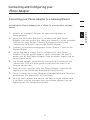
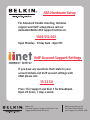
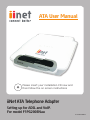
ATA User Manual
Please insert your installation CD now and
then follow the on screen instructions
iiNet ATA Telephone Adapter
Setting up for ADSL and VoIP.
For model F1PG200ENau
F1PG200ENau
Table of Contents
1 Introduction . . . . . . . . . . . . . . . . . . . . . . . . . . . . . . . . . . . . . . 1
2 Product Overview . . . . . . . . . . . . . . . . . . . . . . . . . . . . . . . . . . 2
Key Features . . . . . . . . . . . . . . . . . . . . . . . . . . . . . . . . . . . . 2
3 Knowing your Phone Adapter . . . . . . . . . . . . . . . . . . . . . . . . . 4
Package Contents . . . . . . . . . . . . . . . . . . . . . . . . . . . . . . . . 4
System Requirements . . . . . . . . . . . . . . . . . . . . . . . . . . . . . 4
Product Specifications . . . . . . . . . . . . . . . . . . . . . . . . . . . . . 5
4 Connecting and Configuring your Phone Adapter . . . . . . . . . . 8
Connecting your Phone Adapter
to a Gateway/Router . . . . . . . . . . . . . . . . . . . . . . . . . . . . . . 9
5 Troubleshooting . . . . . . . . . . . . . . . . . . . . . . . . . . . . . . . . . . 10
6 Information . . . . . . . . . . . . . . . . . . . . . . . . . . . . . . . . . . . . . 13
Introduction
1
2
3
4
5
6
section
Thank you for purchasing the Phone Adapter. This User Manual provides
instructions for installing and configuring the Phone Adapter. In minutes,
you will be able to place phone calls to any location in the world
using your standard phone equipment and your broadband Internet
connection.
Product Overview
Key Features
Voice over Internet Phone Dialing
This exciting, new technology allows you to place calls over your
existing broadband Internet connection with the same quality and
functionality as your standard telephone service.
Compatible with both PCs and Mac® Computers
The Phone Adapter supports a variety of networking environments
including Mac OS ® 8.x, 9.x, X v10.x, Linux ® , Windows ® 95, 98, Me,
NT ® , 2000, XP, and others. It requires an Internet browser and a
network adapter that supports TCP/IP (the standard language
of the Internet).
Front-Panel LED Display
Lighted LEDs on the front of the Phone Adapter indicate which
functions are in operation. You’ll know at-a-glance whether your
Phone Adapter is connected to the Internet. This feature eliminates
the need for advanced software and status-monitoring procedures.
Web-Based Advanced User Interface
You can set up the Phone Adapter’s advanced functions easily
through your web browser, without having to install additional
software onto the computer. There are no disks to install or store,
and you can make changes and perform setup functions from any
computer on the network quickly and easily.
NAT IP Address Sharing
Your Phone Adapter employs Network Address Translation (NAT) to
share the single IP address assigned to you by your Internet Service
Provider while saving the cost of adding IP addresses to your Internet
service account.
Universal Plug-and-Play (UPnP) Compatibility
UPnP (Universal Plug-and-Play) is a technology that offers seamless
operation of voice messaging, video messaging, games, and other
applications that are UPnP-compliant.
Product Overview
Built-In Dynamic Host Configuration Protocol (DHCP) Client
2
3
4
5
6
section
Built-In Dynamic Host Configuration Protocol (DHCP) client
on-board makes for the easiest possible connection to your router.
The DHCP server in your router will assign IP addresses to your
Phone Adapter automatically so there is no need for a complicated
networking setup.
1
Knowing your Phone Adapter
Package Contents
• Phone Adapter
• RJ45 Ethernet Networking Cable
• RJ11 Phone Cord
• Power Supply
• User Manual
• Quick Installation Guide
• Features Overview
System Requirements
• Broadband Internet service, such as cable or DSL
• Unused LAN port on a router
Router requirements:
• Connection to a broadband Internet service
• DHCP server support service
• One standard telephone
Knowing your Phone Adapter
1
Product Specifications
2
Standards
3
Protocols Supported
4
SIP, CSMA/CD, TCP/IP, UDP, DHCP (client)
5
Voice Compression
G.711, G.729
6
Management
Browser-Based User Interface
Ports
1 10/100Base-Tx auto-sensing RJ45 port, WAN
2 FXS voice ports (Line 1 and 2)
LEDs
Network: Connection to router
Voice: Line 1, Line 2
Dimensions and Weight
127mm x 119.5mm x 39mm
165g (5.82oz.)
Power
5VDC, 2.4A
The Phone Adapter is designed to be placed on a desktop next to
your telephone or mounted on a wall. All of the cables exit from the
rear of the Phone Adapter for better organization and utility. The
LED indicators are easily visible on the front of the Phone Adapter to
provide you with information about your call and network activity and
status.
section
IEEE 802.3u 10/100Base-Tx Fast Ethernet (WAN)
Knowing your Phone Adapter
[a] Line 2
[b] Line 1
Connection to
Router
Line 2
DC Power
5V/2.4A
Line 1
[c] Connection to Router
[d] Reset
Reset
[e] Power
[a]
[b]
[c]
[d]
[e]
(a/b) Phone Ports
These ports are for connection to your telephone handset. Use the
RJ11 cable that was provided with the Phone Adapter to connect the
telephone to these ports.
(c) Connection to Router
This port is for connection to your router. Use the cable that was
provided with the Phone Adapter to connect the router to this port.
Or you may use it to connect to your existing router setup.
(d) Reset Switch
The “Reset” button is used in rare cases when the Phone Adapter
may function improperly. Resetting the Phone Adapter will restore the
Phone Adapter’s normal operation while maintaining the programmed
settings. You can also restore the factory default settings by using the
“Reset” button. Use the restore option in instances where you may
have forgotten your custom password.
1. Resetting the Phone Adapter
Push and release the “Reset” button. The lights on the Phone Adapter will momentarily flash while the unit reboots.
2. Restoring the Factory Defaults
P ress and hold the “Reset” button for at least five seconds, then
release it. The lights on the Phone Adapter will momentarily flash
while the unit reboots.
Knowing your Phone Adapter
1
(e) Power Jack
Connect the included 5VDC, 2.4A power supply to this jack.
2
LEDs
4
5
A
B
When you apply power to the Phone Adapter or restart it, a short
period of time elapses while the Phone Adapter starts up (about 30
seconds). During this time, you will see all the LEDs flash on, and
then off. When the Phone Adapter has completely started up, the
power LED will light, indicating the Phone Adapter is ready for use.
A. Connected LED
This LED lights in GREEN to indicate that your modem is
connected to the router. It blinks rapidly when information is
being sent over the port between the Phone Adapter and the
modem.
Solid Green
Connected to router
Blinking Green
Internet activity
Off
No physical connection
B. Phone LED
These LED lights (1 and 2) illuminate in GREEN to indicate that
your Phone Adapter is ready to make or accept a call.
Solid Green
Phone Adapter is ready to make or accept a
call
Off
Phone Adapter did not successfully register
for service
6
section
3
Connecting and Configuring your
Phone Adapter
Router Requirements
Your cable or DSL router must be equipped with an RJ45 Ethernet
port. Many routers have both an RJ45 Ethernet port and a USB
connection. If you have a router with both Ethernet and USB, and you
are using the USB connection at this time, you will be instructed to
use the RJ45 Ethernet port during the installation procedure. If your
router has only a USB port, you can request a different type of router
from your ISP, or you can, in some cases, purchase a router that has
an RJ45 Ethernet port on it.
ALWAYS INSTALL YOUR NETWORK FIRST! IF YOU ARE SETTING
UP YOUR NETWORK FOR THE FIRST TIME, IT IS IMPORTANT
THAT YOUR NETWORK IS CONNECTED AND RUNNING BEFORE
ATTEMPTING TO SET UP THE PHONE ADAPTER. BE SURE THAT AT
LEAST ONE COMPUTER ON YOUR NETWORK HAS ACCESS TO THE
INTERNET BEFORE SETTING UP THE PHONE ADAPTER.
Determining your Current Network and Connection
The Phone Adapter can only function as a client in an existing
network configuration. For example, if you currently have broadband
access and a gateway/router installed in your location, you may add
the Phone Adapter as a client to your network.
This is the simplest and fastest method to install your Phone Adapter.
Connecting and Configuring your
Phone Adapter
Connecting your Phone Adapter to a Gateway/Router
Installing the Phone Adapter as a client to a router that already
exists.
home gateway.
2. Using the Ethernet cable that is included with your Phone
Adapter, take one end of the cable and connect it to the available
LAN port on your Router. Connect the opposite end to the
“Connection to Router” port on the Phone Adapter.
3. Connect a standard analog phone to the “Phone 1” port on the
Phone Adapter.
4. Locate the power supply that is included with your Phone
Adapter. Plug the power supply’s small connector into the DC
power jack on the Phone Adapter. Plug the power supply into an
empty power outlet.
5. The Phone Adapter automatically connects to the Internet.The
“connected” LED will blink green to indicate that there is an
Internet connection.
6. Wait up to five minutes while the Phone Adapter automatically
registers to the iiNetphone Broadband Phone Service.
7. Once a connection to the iiNetphone Broadband Phone Service is
established, the phone LED will illuminate.
8. Pick up your handset and ensure you hear a single audible tone.
If you hear a series of beeps then your phone adapter has not
registered on the iiNetphone network.
2
3
4
5
6
section
1. Identify an available LAN port on your existing router or
1
Troubleshooting
Problem:
• Phone Adapter is not working.
• LEDs do not come on.
Solution:
If the LED indicators are not ON, the problem may be that the Phone
Adapter is not connected properly.
Verify that the Phone Adapter is plugged into a power source. Check
to see that the cables are connected to the correct ports and that
they are secure.
Problem:
There is no dial tone and the “Line 1” (or “Line 2”) LED is not lit.
Solution:
1. Power off your cable or DSL modem by unplugging its
power adapter.
2. Power off the router by unplugging its power adapter.
3. Disconnect all Ethernet cables from both the modem and router.
4. Wait for three minutes, and then power on your cable or DSL
modem by plugging its power adapter into an electrical outlet.
5. Wait for three minutes, and then power on your router by
plugging its power adapter into an electrical outlet.
6. Wait for five minutes, and then power on the Phone Adapter by
plugging its power adapter into an electrical outlet.
7. Make sure the RJ11 telephone cable between the telephone
handset and the Phone Adapter is connected to the Phone
Adapter’s “Line 1” port, and that the RJ11 telephone cable is
firmly in place.
8. Make sure the “connected” LED on the front panel of the Phone
Adapter is lit, then check your router and network connection to
the Internet.
10
Troubleshooting
1
Problem:
• The Phone Adapter cannot connect to the router.
• The “connected” light does not come on.
2
3
Solution:
Make sure the network cable between the router and the Phone
Adapter is connected to the Phone Adapter’s “Connection to
Router” port and that the cable is firmly in place. Power off the
router for a few seconds and then power it on again.
11
4
5
6
section
If your Phone Adapter appears to be powered but the “connected”
light is not green, the problem may be that your router and Phone
Adapter are not connected properly.
Troubleshooting
Technical Support
You can find technical support information at http://www.iinet.net.au
or contact iiNet customer support on 13 22 58.
12
Information
1
FCC Statement
DECLARATION OF CONFORMITY WITH FCC RULES FOR
ELECTROMAGNETIC COMPATIBILITY
We, Belkin Corporation, of 501 West Walnut Street, Compton,
CA 90220, declare under our sole responsibility that the product,
F1PG200ENau
Caution: Exposure to Radio Frequency Radiation.
The radiated output power of this device is far below the FCC radio
frequency exposure limits. Nevertheless, the device shall be used in
such a manner that the potential for human contact during normal
operation is minimized. When connecting an external antenna to the
device, the antenna shall be placed in such a manner to minimize the
potential for human contact during normal operation. In order to avoid
the possibility of exceeding the FCC radio frequency exposure limits,
human proximity to the antenna shall not be less than 20cm (8 inches)
during normal operation.
Federal Communications Commission Notice
This equipment has been tested and found to comply with the limits
for a Class B digital device, pursuant to Part 15 of the FCC Rules.
These limits are designed to provide reasonable protection against
harmful interference in a residential installation. This equipment
generates, uses, and can radiate radio frequency energy. If this
equipment does cause harmful interference to radio or television
reception, which can be determined by turning the equipment off and
on, the user is encouraged to try and correct the interference by one
or more of the following measures:
•
Reorient or relocate the receiving antenna.
• Increase the distance between the equipment and the receiver.
• Connect the equipment to an outlet on a circuit different from
that to which the receiver is connected.
• Consult the dealer or an experienced radio/TV technician for help.
13
3
4
5
6
section
to which this declaration relates, complies with Part 15 of the
FCC Rules. Operation is subject to the following two conditions:
(1) this device may not cause harmful interference, and (2)
this device must accept any interference received, including
interference that may cause undesired operation.
2
Information
Modifications
The FCC requires the user to be notified that any changes or
modifications to this device that are not expressly approved by Belkin
Corporation may void the user’s authority to operate the equipment.
Canada-Industry Canada (IC)
The wireless radio of this device complies with RSS 139 & RSS
210 Industry Canada. This Class B digital apparatus complies with
Canadian ICES-003. Cet appareil numérique de la classe B conforme
á la norme NMB-003 du Canada.
Europe-European Union Notice
Radio products with the CE 0682 or CE alert marking comply with
the R&TTE Directive (1995/5/EC) issued by the Commission of
the European Community. Compliance with this directive implies
conformity to the following European Norms (in brackets are the
equivalent international standards).
• EN 60950 (IEC60950) – Product Safety
• EN 300 328 Technical requirement for radio equipment
• ETS 300 826 General EMC requirements for radio equipment.
To determine the type of transmitter, check the identification label
on your Belkin product. Products with the CE marking comply with
the EMC Directive (89/336/EEC) and the Low Voltage Directive
(72/23/EEC) issued by the Commission of the European Community.
Compliance with these directives implies conformity to the following
European Norms (in brackets are the equivalent international
standards).
• EN 55022 (CISPR 22) – Electromagnetic Interference
• EN 55024 (IEC61000-4-2,3,4,5,6,8,11) – Electromagnetic Immunity
• EN 61000-3-2 (IEC610000-3-2) – Power Line Harmonics
• EN 61000-3-3 (IEC610000) – Power Line Flicker
• EN 60950 (IEC60950) – Product Safety
Products that contain the radio transmitter are labeled with CE 0682
or CE alert marking and may also carry the CE logo.
14
Information
Belkin Corporation Limited 2-Year Product Warranty
Belkin Corporation warrants this product against defects in materials
and workmanship for 2 years. If a defect is discovered, Belkin will,
at its option, repair or replace the product at no charge provided it
is returned during the warranty period, with transportation charges
prepaid, to the authorized Belkin dealer from whom you purchased
the product. Proof of purchase may be required.
THE WARRANTY AND REMEDIES SET FORTH ABOVE ARE
EXCLUSIVE IN LIEU OF ALL OTHERS, WHETHER ORAL OR WRITTEN,
EXPRESSED OR IMPLIED. BELKIN SPECIFICALLY DISCLAIMS ANY
AND ALL IMPLIED WARRANTIES, INCLUDING, WITHOUT LIMITATION,
WARRANTIES OF MERCHANTABILITY AND FITNESS FOR A
PARTICULAR PURPOSE.
No Belkin dealer, agent, or employee is authorized to make any
modification, extension, or addition to this warranty.
BELKIN IS NOT RESPONSIBLE FOR SPECIAL, INCIDENTAL, OR
CONSEQUENTIAL DAMAGES RESULTING FROM ANY BREACH OF
WARRANTY, OR UNDER ANY OTHER LEGAL THEORY, INCLUDING
BUT NOT LIMITED TO, LOST PROFITS, DOWNTIME, GOODWILL,
DAMAGE TO OR REPROGRAMMING OR REPRODUCING ANY
PROGRAM OR DATA STORED IN, OR USED WITH, BELKIN
PRODUCTS.
Some states do not allow the exclusion or limitation of incidental or
consequential damages or exclusions of implied warranties, so the
above limitations or exclusions may not apply to you. This warranty
gives you specific legal rights, and you may also have other rights
that vary from state to state.
15
2
3
4
5
6
section
This warranty does not apply if the product has been damaged by
accident, abuse, misuse, or misapplication; if the product has been
modified without the written permission of Belkin; or if any Belkin
serial number has been removed or defaced.
1
ATA Hardware Setup
For Advanced trouble shooting, technical
support and VoIP setup please call our
dedicated Belkin ATA support hotline on:
1300 552 002
Open Monday - Friday 8am - 8pm EST
VoIP Account Support/Settings
If you have any questions that relate to your
account details and VoIP account settings with
iiNet please call:
13 22 58
Press 1 for Support and then 1 for Broadband.
Open 24 hours, 7 days a week.
Belkin, Inc.
4 Pioneer Avenue, Tuggerah Business Park
Tuggerah NSW 2259, Australia
Belkin International, Inc.
501 West Walnut Street Los Angeles,CA, 90220, USA