1
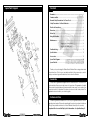
©
0700
6” Bench Grinder with Sanding Belt
Model CBG6SB
Part Number 6500032
Operating & Maintenance
Instructions
Spare Parts List
No. Description
Parts and Service
For Spare Parts and Servicing, please contact your local dealer, or
Clarke International on one of the following Numbers:
Parts and Service Tel: 0208 988 7400
Parts and Service Fax: 0208 558 3622
or email as follows:
Parts: [email protected]
Service: [email protected]
Part No.
No. Description
Part No.
I
Bolt
HT6SB001
41 Screw
HT6SB041
2
Outer guard
HT6SB002
42 Spring washer
HT6SB042
3
Nut
HT6SB003
43 Cord clamp
HT6SB043
4
Flange
HT6SB004
45 Cord sleeve
HT6SB045
5
Paper Blotter
HT6SB005
46 Nut
HT6SB046
6
Wheel
HT6SB006
47 Tooth washer
HT6SB047
7
Ring guard
HT6SB007
48 Capacitor bracket
HT6SB048
8
Screw
HT6SB008
49 Washer
HT6SB049
9
Spring washer
HT6SB009
50 Spring washer
HT6SB050
10 Washer
HT6SB010
51 Screw
HT6SB051
11 Spark Arrester
HT6SB011
52 Capacitor
HT6SB052
12 Bolt
HT6SB012
53 Plug cord
HT6SB053
13 Washer
HT6SB013
54 Screw
HT6SB054
14 Eyeshield
HT6SB014
55 Nut
HT6SB055
15 Spring washer
HT6SB015
56 Knob
HT6SB056
16 Nut
HT6SB016
57 Spring washer
HT6SB057
17 Screw
HT6SB017
58 Washer
HT6SB058
18 Spring washer
HT6SB018
59 Belt cover
HT6SB059
19 Inner guard
HT6SB019
60 Bracket
HT6SB060
20 Rotor
HT6SB020
61 Top Roller
HT6SB061
21 Motor cover
HT6SB021
62 Belt (5 Pack)
HT6SB062
22 Nut
HT6SB022
63 Outer cover
HT6SB063
23 Spring washer
HT6SB023
64 Screw
HT6SB064
24 Stator
HT6SB024
65 Spring washer
HT6SB065
25 Motor cover
HT6SB025
66 Washer
HT6SB066
26 Tool rest
HT6SB026
67 Square neck screw
HT6SB067
27 Bolt
HT6SB027
68 Screw
HT6SB068
If you have any problems using or setting up your Grinder call
the Clarke Helpline on,
28 Spring washer
HT6SB028
69 Spring washer
HT6SB069
29 Washer
HT6SB029
70 Belt support bracket
HT6SB070
0208 988 7400
30 Spring washer
HT6SB030
71 Spring washer
HT6SB071
31 Bolt
HT6SB031
72 Nut
HT6SB072
32 Washer
HT6SB032
73 Spring
HT6SB073
33 Spring washer
HT6SB033
74 Spring pin
HT6SB074
34 Screw
HT6SB034
75 Nut
HT6SB075
35 Switch
HT6SB035
76 Knob
HT6SB076
36 Base
HT6SB036
77 Spring washer
HT6SB077
37 Base plate
HT6SB037
78 Washer
HT6SB078
36 Screw
HT6SB038
79 Tool rest
HT6SB079
39 Tooth washer
HT6SB039
80 Drive Roller
HT6SB080
40 Rubber feet
HT6SB040
81 Nut
HT6SB081
Press 1 for Parts : 2 for Technical Assistance
© Copyright - Clarke International. All rights reserved. July,2000
-2-
- 15 -
Spare Parts Diagram
Contents
Guarantee ...................................................................................................... 3
Features and Use ........................................................................................... 3
General Safety Precautions : For Power Tools ............................................. 4
Safety Precautions : For Bench Grinders ..................................................... 5
Electrical Connections .................................................................................. 6
Overview ......................................................................................................... 7
Before Use ....................................................................................................... 7
Using the Machine ......................................................................................... 8
Maintenance .................................................................................................. 9
Changing the Grinding Wheel ......................................... 10
Changing the Sanding Belt .............................................. 11
Troubleshooting ............................................................................................ 12
Specifications ............................................................................................... 13
Accessories .................................................................................................. 13
Spare Parts Diagram .................................................................................... 14
Spare Parts List .............................................................................................. 15
Thank you for purchasing this Clarke Bench Grinder. Before using please read
these instructions. This is for your own safety and that of others around you, and to
help you achieve long and trouble free service from the Grinder.
Guarantee
This product is guaranteed against faults in manufacture for 12 months from
purchase date. Keep your receipt as proof of purchase. This guarantee is invalid
if the product has been abused or tampered with in any way, or not used for the
purpose for which it is intended. The reason for return must be clearly stated. This
guarantee does not affect your statutory rights.
Features and Use
This Bench grinder is intended for D.I.Y use only. The grinder features a 150mm
grinding wheel and a 50mm wide sanding belt mounted on a base that allows
fitting to any suitable work bench or Bench Grinder Stand (See Accessories).
Important: Do not exceed the Duty Cycle for the machine....See Specifications, p13.
- 14 -
-3-
General Safety Precautions : For Power Tools
WARNING! Read these safety instructions before using the equipment.
Keep Children away when using Power Tools.
Eye Protection manufactured to the current European Safety Standards
should be worn when using Power Tools.
Specifications
Model No ................................................................. CBG 6SB
Part No ..................................................................... 6500032
Overall Dimensions ................................................. 340(H) x 340(W) x 300(D)
Gross Weight ........................................................... 9,8 Kg
Net Weight .............................................................. 8.9kg
✔ Always
check for damage before using the tool. Any damaged part should be checked
to ensure that it will operate properly and perform its intended function.
Check for alignment of moving parts, breakage of parts, mountings and any other
condition that may affect the tools’ operation. Any damage should be properly
repaired or the part replaced. If in doubt, Do Not use the tool. Consult your local dealer.
Motor ........................................................................ 230 Volts AC 50Hz 1Phase
Power Rating ........................................................... 240 Watts
Always ensure that adequate lighting is available. A minimum intensity of 300 lux
Grinder
should be provided. Ensure that lighting is placed so that you will not be working in
your own shadow.
No Load Wheel Speed ........................................... 2800 RPM
Always wear safety goggles manufactured to the latest European Safety Standards,
everyday eyeglasses do not have impact resistant lenses, they are NOT safety glasses.
Duty Cycle ............................................................... 2min ON, 2min OFF
Wheel Diameter ...................................................... 150mm
Wheel Width ............................................................ 20mm
Bore .......................................................................... 13 mm
Always use a face or dust mask if operation is particularly dusty.
Always disconnect the tool from the power supply before servicing and when
Sanding Belt
changing accessories.
No Load Belt speed ................................................ 15.5 M/s
Always use in a suitable environment. Don’t use power tools in damp or wet locations
Belt Length ............................................................... 686 mm
Belt Width ................................................................. 50mm
or expose them to rain. Keep your work area well illuminated. Do Not use in explosive
atmosphere (around paint, flammable liquids etc.).
Always keep work area clean and clear. Cluttered areas and benches invite accidents.
Always wear proper apparel. Loose clothing or jewellery may get caught in moving
parts. Wear protective hair covering to contain long hair.
Accessories
Always handle equipment with care. Do Not carry the tool by its’ electric cable, or
yank the cable to disconnect it from the power supply.
Always ensure the switch is OFF before plugging in to mains. This will ensure the
Description
Part No.
equipment does not start accidentally.
Grinding Wheel - Fine
Grinding Wheel - Medium
Grinding Wheel - Course
Grinding Wheel Dressing Tool - Model No. GWD 1.
Sanding Belts1 - Fine (Pack of 5)
Sanding Belts1 - Medium (Pack of 5)
Sanding Belts1 - Course (Pack of 5)
Bench Grinder Stand
6501135
6501089
6501088
6501120
6502115
6502120
6502125
6501140
Always follow the maintenance instructions. Keep tools clean and maintained for the
best and safest performance.
✗
Never force the tool. It will do a better and safer job at the rate for which it was
designed.
Never operate equipment whilst under the influence of drugs, alcohol or any
medication.
-4-
- 13 -
Safety Precautions : For Bench Grinders
Troubleshooting :
Problem
The Motor does not start
when switched on.
Unusual vibration when the
machine is switched on.
Excessive noise when the
machine is switched on.
Possible Cause
1. The power supply is not
properly connected.
1. Check and rectify
2. The Fuse has blown.
2. Renew Fuse
3. The motor is burnt out.
3. Contact Clarke Service
1. The grinding wheel is not
properly fitted
1. Refit the grinding wheel
(as described in Maintenance)
2. The grinding wheel is
damaged.
2. Replace the grinding
wheel immediately
(as described in Maintenance)
Excessive noise
Ear Protection manufactured to the current European Safety Standards
should be worn when operating grinding equipment.
3. The Sanding belt tracking
and/or tension is
incorrectly set.
3. Reset the sanding belt
tracking and (or) tension
(as described in Maintenance)
4. The Unit is not mounted
correctly
4. Ensure the Unit is
mounted correctly to a
stable surface
1. The Covers are not fitted
securely to the machine
1. Ensure all cover
fasteners are secure.
2. A tool rest touching
the grinding wheel or
sanding belt
2. Ensure the tool rests and
spark arrester is set
correctly
(as described in Maintenance)
3. Contact Clarke Servicing
3. The Motor bearings are
worn or damaged
✔ Always
replace a cracked wheel immediately.
Always use guards and eyeshield.
Always adjust distance between wheel and tool rest to maintain 1/16” (1.6mm)
separation as the diameter of the wheel will decrease with use.
Always use a grinding wheel suitable for the speed of grinder. (See Specifications).
Always stand slightly to one side of the bench grinder during operation, not directly
in front.
Always allow one minute of free rotation for a new grinding wheel: Should the
new grinding wheel be faulty it will shatter within the first minute of running.
✗
Never use the side of the grinding wheel. Use only the front face.
Never leave a grinding wheel unattended. TURN POWER OFF. Do not leave until it
comes to a complete stop.
Do not remove the wheel guard except when changing a worn wheel.
Do not use the grinding wheel for any kind of cutting.
Do not over stress the grinding wheel.
1. Excessive force is being
applied to the grinder /
sander
1. Apply less force when
using the machine.
2. The grinding wheel is
damaged.
2. Replace the grinding
wheel immediately
(as described in Maintenance)
3. The Sanding belt tracking
is incorrectly set.
3. Reset the sanding belt
tracking
(as described in Maintenance)
4. The sanding belt tension is
set too high
4. Set the sanding belt
tension
(as described in Maintenance)
- 12 -
Eye Protection manufactured to the current European Safety Standards
should be worn when operating grinding equipment.
Remedy
USE ONLY APPROVED REPLACEMENT GRINDING WHEELS. Contact your local dealer or
Clarke International for approved replacement grinding wheels and accessories. The
use of inferior accessories could result in personal injury or damage to property.
-5-
(f)
Electrical Connections
Changing the Sanding Belt
Top Roller
Securing
Knob
WARNING! This Appliance must be Earthed
fig (9)
Tracking
Adjustment
Screw
Connect the mains lead to a standard 230V (50Hz) electrical supply through an
approved 13 Amp BS1363 plug, or a suitably fused isolator switch
fig (9a)
Cover
Belt
Tensioning
Nut
IMPORTANT : The wires in the mains lead are coloured in accordance with the
following code:
Green & Yellow ........... Earth
Blue .............................. Neutral
Brown ........................... Live
As the colours of the flexible cord of this appliance may not correspond with the coloured
markings identifying terminals in your plug proceed as follows:
•
Connect GREEN & YELLOW coloured cord to plug terminal marked with a letter E
or Earth symbol “
”or coloured GREEN or GREEN & YELLOW.
•
Connect BROWN coloured cord to plug terminal marked with a letter L or
coloured RED
•
Work Rest
Securing Knob
To renew or change the Sanding Belt, proceed as follows:
1.
Switch off and unplug from mains power supply. Remove the sander cover by
unscrewing the three securing screws .
2.
Slacken the sander work rest securing knob, and pull the work rest away from belt.
3.
Slacken the belt tensioning nut until the belt feels loose on the rollers.
4.
Slacken the top roller securing knob, allowing the top pulley to move slightly off its axis (as
shown in (fig (9a)).
5.
Slide the belt off and replace with a new one, ensuring it lies centrally on the top and
bottom rollers
6.
Retighten the top roller securing knob until it becomes firm...but NOT too tight.
7.
Tighten the belt tension adjuster nut until it also becomes firm. DO NOT overtighten.
The belt should now be fairly taught, and positioned centrally on the rollers.
Connect BLUE coloured cord to plug terminal marked with a letter N or coloured BLACK
IMPORTANT: If this appliance is fitted with a plug which is moulded on to the electric
cable (i.e. non- re-wireable) please note:
1. The plug must be thrown away if it is cut from the electric cable. There is a danger of
electric shock if it is subsequently inserted into a socket outlet.
2. Never use the plug without the fuse cover fitted.
3. Should you wish to replace a detachable fuse carrier, ensure that the correct
replacement is used (as indicated by marking or colour code).
4. Replacement fuse covers can be obtained from your local dealer or most electrical
stockists.
Fuse Rating
The fuse in the plug must be replaced with one of the same rating (13 amps) and this
replacement must be ASTA approved to BS1362.
IMPORTANT: If in any doubt, do not attempt any electrical repair yourself.
IMPORTANT ! : The belt needs just enough tension to ensure that it does not slip on the pulleys
whilst under load, however too much tension will shorten the working life of the belt and the
machine.
8.
Replace the sanding belt cover, then adjust and tighten the work rest.
9.
Rotate the belt by hand whilst screwing the Tracking Adjustment Screw in or out to
ensure the belt runs centrally about the rollers. Turn the screw anticlockwise to move
the belt outwards (towards the outer cover), or clockwise to move inwards (as shown
in fig(10)).
10. When reasonably satisfied, and
taking ALL precautions, plug the
machine in to the mains and
switch ON.
Make fine adjustments with the
Tracking Adjustment screw if
necessary.
fig (10)
Tracking
Adjustment
Screw
Anticlockwise
Consult a qualified technician
-6-
Clockwise
- 11 -
(d)
Changing the Grinding Wheel
Figure (1) Overview
1
To renew or change the grinding wheel, follow the steps given below.
1.
Switch off and unplug from mains power supply. Remove the grinding wheel covers
by unscrewing the nuts securing the three retaining screws, and the sanding belt
cover by unscrewing its three retaining screws.
2.
Remove the spark arrester bracket and eye shield by unscrewing the single mounting
screw. Slacken the tool rest mounting bolts, and pull the bracket away from the
wheel.
3.
Hold the sanding belt roller firmly to stop the shaft rotating and remove the nut
and flange holding the grinding wheel, remembering that the nut has a LEFT
HAND THREAD.
4.
Remove the used wheel and replace with a new one, ensuring . . .
12
2
11
10
3
9
(a) The paper blotters and flanges are in place either side of the wheel.
(b) You do not overtighten the wheel nut.
4
5
5.
Readjust the tool rest and spark arrester brackets as described in Maintenance (Page 9).
6.
Switch ON the machine and allow it to rotate freely for at least one minute.
5
fig (8)
Outer cover
6
7
8
Wheel
Spark Arrester
1
Grinding Wheel Cover
7
ON / OFF Switch
2
Eye Shield / Spark Arrester
8
Bench Mounting Holes
3
Grinding Wheel
9
Sander Work Rest
4
Tool Rest
10
Sanding Belt Cover
5
Motor Housing
11
Sanding Belt
6
Base
12
Top Roller Securing Knob
Before Use
Except for the spark arrester and the eye shield the
grinder comes fully assembled. Screw the spark
arrester to the bracket on the wheel cover using
the single screw provided ensuring a gap of 1.6mm
is maintained between the wheel and the spark
arrester, as shown in fig(5).
Nut
Flanges
Tool Rest
(e)
fig (2)
The following checks must be made before using
the grinder or sander
Dressing the Grinding Wheel
It will be necessary from time to time to dress the wheel to obtain a true working surface. This
should be done ONLY with an approved Dressing Tool, which can be obtained from your
CLARKE dealer, quoting Model No. GWD -1.
Part No. 6501120.
1. Ensure there is no damage to the grinder and all
parts are present and correctly fitted. If any
damage is apparent, contact your Clarke dealer.
2. Ensure that the tool rest, spark arrester, and sander
work rest are properly fitted and adjusted.(as
detailed in Maintenance, page 9)
3. Ensure that the grinder is mounted securely to a suitable, stable work surface using the
four bolt holes provided in ther base
-10 -
-7-
Using the Machine
(a)
Maintenance
WARNING ! Ensure the grinder is disconnected from the mains before carrying out any
maintenance.
Due to the reduction in diameter of the grinding wheel caused by wear, it is necessary
to check and adjust the clearance gap of the spark arrester and tool rest to maintain
suitable clearance from the wheel. It is recommended that a gap of 1.6 mm is maintained.
Using the Grinding Wheel
Note : Although the unit is supplied assembled there is a possibility that the guards may
have moved during transit. Check the guards and make any adjustments necessary
(see Maintenance ) before starting the motor.
1. Turn the wheel by hand to ensure it is free, then switch ON by pushing the rocker switch so that
the “ I “ is depressed. To switch OFF push the switch so that the “ 0 ” is depressed.
(a)
Slacken the spark arrestor securing screw and
position the arrester so that the recess is adjacent
to the wheel with a clearance of approximately
1.6 mm, (as shown in fig (5)). Tighten the screw to
secure in position.
2. Allow the machine to reach full speed, then hold the tool firmly on the tool rest and apply
slight pressure on to the grinding wheel, allowing the grinder to do the work.
Note : Never attempt to grind a piece of metal that is thinner than the gap between the tool
rest and the wheel (1.6 mm)
WARNING ! Applying excessive force to the grinding wheel can be dangerous and could
cause damage to the machine.
WARNING ! Do not attempt to use the side of the grinding wheel
fig (3)
Note: The clearance between the grinding wheel
and tool rest should be maintained. If the clearance
gap is greater than the thickness of the metal being
ground there is a danger that the force of grinding
will cause the work piece to be pulled into the gap
with great force and is potentially very dangerous.
An incorrect gap could also cause “chatter” which
could result in damage to the wheel.
1. Position the sander work rest as required (see fig. 4) and adjust as stated in Maintenance (page 9)
2. Switch the motor ON by pushing the rocker switch so that the “ I ” is depressed, and allow the
machine to reach full speed. To switch the motor OFF push the switch so that the “ 0 ” is depressed.
3. Hold the workpiece firmly on the work rest and apply slight pressure to the sanding belt, allowing
the machine to do the work. If the belt does not run centrally, refer to page 11.
(2) For general sanding and thicker work
fig (4)
(c)
fig (6)
Tool Rest
Setting the Sander Tool Rest
Slacken the knob that secures the work rest
in place and position the rest so that it is adjacent
to the belt edge and at 900 to the belts surface
with approximately 1.6 mm clearance (as shown
in fig (7)).Tighten the knob to secure in position.
Note: It is recommended that a set square is used to
gain the 900 angle. This will ensure an accurate square
finish when the workpiece is placed on rest.
-8-
Spark Arrester
Setting the Tool Rest
Slacken the two tool rest securing bolts and position
the rest so that it is adjacent to the wheel with a
clearance of approximately 1.6 mm, (as shown in
fig (6)). Tighten the two bolts to secure in position.
Using the Sanding Belt
(1) For thin work pieces or sanding curves
fig (5)
Note: The Plastic Eye Shield, attached to the spark
arrester should be tight enough so that it does not
move under operational vibration, but loose enough
so that it may easily be positioned by hand.
(b)
(b)
Setting the Spark Arrester / Shield
-9-
fig (7)
Work Rest