1
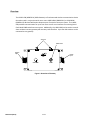
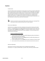
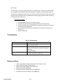
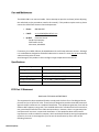
USER MANUAL 3800 Gateway U9922-G38 (P/N: 40995G-01) 19541P-43 (03-12) 2012 DAVID CLARK COMPANY INCORPORATED Cautions and Warnings READ AND SAVE THESE INSTRUCTIONS. Follow the instructions in this installation manual. These instructions must be followed to avoid damage to this product and associated equipment. Product operation and reliability depends on proper usage. DO NOT INSTALL ANY DAVID CLARK COMPANY PRODUCT THAT APPEARS DAMAGED. Upon unpacking your David Clark product, inspect the contents for shipping damage. If damage is apparent, immediately file a claim with the carrier and notify your David Clark product supplier. ELECTRICAL HAZARD - Disconnect electrical power when making any internal adjustments or repairs. All repairs should be performed by a representative or authorized agent of the David Clark Company. STATIC HAZARD - Static electricity can damage components. Therefore, be sure to ground yourself before opening or installing components. LI-POLYMER - This product is used with Li-Polymer batteries. Do not incinerate, disassemble, short circuit, or expose the battery to high temperatures. Battery must be disposed of properly in accordance with local regulations. 19541P-43 (03-12) 1 of 9 Overview The U9922-G38 (40995G-01) 3800 Gateway is a fixed-mounted wireless communication device that when used in conjunction with one or more U9910-BSW (40992G-01) or U9912-BSW (40992G-02) Wireless Belt Stations becomes part of a wireless intercom system. The U9922G38 provides communication for up to four users as well as an interface to an existing David Clark Model 3800 wired intercom system. Additionally, the U9922-G38 can be used as a standalone wireless intercom gateway with two-way radio interface. Up to four belt stations can be connected to one gateway. Antenna Status LED System Input R Radio Input VOLUME LINK Figure 1: Overview of Gateway 19541P-43 (03-12) 2 of 9 Installation Intercom Interface The U9922-G38 can be configured in one of two ways: 3800 interface and stand-alone. 3800 Interface This configuration adds wireless capability to an existing 3800 wired intercom system and can replace a U3811 or U3815 radio interface module (see 3800 system documentation for further details.) In this way, all wired and wireless users may communicate with each other as well as talk over and listen to a two-way radio. A C38-xx system cable and optional C3821 radio interface cable are required for this configuration. Stand-alone Stand-alone configuration creates an ad-hoc wireless intercom and adds access to a twoway radio. This configuration does not connect to a 3800 wired intercom system. A C9922PW (18748G-24) power cable and optional C3821 radio interface cable are required for this configuration. Antenna The U9922-G38 has two external antenna connections and is supplied with one whip style antenna. In most applications a single whip antenna is sufficient. However the optional remote antenna kit (P/N: 40688G-93 for mag-mount, 40688G-96 for permanent install) is available should more range be desired. In this case, we recommend keeping one whip antenna connected directly to the U9922-G38 and routing the remote antenna somewhere else (such as on the roof of a vehicle). Choose an open, clear location for the remote antenna and route the coaxial cable away from any busy areas, preferably behind panels or in conduits. This device has been designed to operate with the antennas listed below, and having a maximum gain of 3 dB. Antennas not included in this list or having a gain greater than 3 dB are strictly prohibited for use with this device. The required antenna impedance is 50 ohms. Acceptable antennas for use with this product: • • • 19541P-43 (03-12) Whip Antenna (P/N: 40688G-92) Remote Antenna Kit, Mag-Mount (P/N: 40688G-93) Remote Antenna Kit, Permanent (P/N: 40688G-96) 3 of 9 Linking Before a belt station and a gateway can be connected, they must first be linked. As a security measure, the close-link feature requires devices to be in proximity of about 1 to 3 ft (0.3 to 0.9m) in order to successfully link. This ensures that the units are not inadvertently linked with other units on the premises. Linking procedure: 1. Ensure units are within 1 to 3 ft (0.3 to 0.9m) of each other. 2. Simultaneously (within 1-2 sec) press and release the LINK button on the U9922-G38 and the LINK/PTT button on the belt station to link with. 3. Amber LED’s will flash quickly on both devices. A momentary red LED indicates a successful close-link. 4. Upon successful link the U9922-G38 will attempt to establish a connection with the belt station. 5. Upon successfully establishing connection the LED on the gateway will flash a green pattern corresponding to the number of belt stations connected. Tip: Once linked, the devices will not need to be linked again unless they are purged (see Purging). Each belt station is able to be linked to only one gateway at a time. A gateway can have up to six belt stations linked and be connected to four of those six at one time. Status Indications The LINK button has a multi-color LED in the center which serves as a status indication for the gateway. Table 1 below lists these states. Table 1: LED Status Indications LED Color Red Red Red Red Orange Orange Orange Green 19541P-43 (03-12) Blink Rate Solid Once Once Any Slow Fast Solid Slow 4 of 9 Status Initializing/power up Connection Dropped Connection Established Low battery (approx. 1 hr remaining) Idle/Disconnected Linking/Connection in Progress PTT asserted Connected (pattern indicates number of belt stations connected) Operation Communication All connected belt stations will be able to communicate with each other through the U9922-G38 while in range (and per the VOX settings on each VOX belt station.) Additionally, all belt station users will have communication over the intercom. If a two-way radio is installed to the U9922G38, pressing the PTT button on a VOX belt station will allow the user to transmit over the system’s two-way radio. Pressing the PTT overrides the VOX setting on a VOX belt station. Multiple belt station users may PTT and thus speak over the two-way radio simultaneously. For more information consult the user manual for the belt station. Tip: Wireless users who are not pressing PTT while another wireless user is pressing PTT will not be heard on the wired intercom while the PTT remains pressed. Intercom Level Adjustment Audio levels can vary between intercoms, mainly due to the system level setting on the wired intercom. To compensate for this, the U9922-G38 has the ability to adjust its receive level from the intercom using the Volume knob (see Figure 1). Turning this knob will increase or decrease the audio level coming from the wired intercom into the gateway. Perform this adjustment to obtain optimum performance. Intercom Level Adjustment Procedure 1. Connect at least one belt station to the U9922-G38 gateway and ensure sidetone is present (see belt station User Manual). 2. Begin speaking and slowly turn the Volume knob on the U9922-G38 clockwise until you hear an echo of your own voice. 3. Continue speaking and turn the Volume knob counter-clockwise until the echo stops. 4. You may wish to verify communication with someone hard-wired to the intercom. Radio Level Adjustment Audio levels to and from a two-way radio can also vary between radio models and manufacturers. To adjust the U9922-G38 for a particular radio, follow the procedures below. 19541P-43 (03-12) 5 of 9 Radio Transmit Level Adjustment Procedure Note: A radio service monitor is recommended for this adjustment. 1. Connect at least one belt station to the U9922-G38 gateway and ensure sidetone is present (see belt station User Manual). 2. Open the cover of the U9922-G38 and find the large silver knob. 3. Press and hold the PTT and speak clearly and loudly into the microphone. 4. Slowly turn the knob until the radio service monitor reads 4.0-4.5kHz deviation. a. Clockwise to increase level; counter-clockwise to decrease Radio Receive Level Adjustment Procedure 1. Connect at least one belt station to the U9922-G38 gateway and ensure side-tone is present (see belt station User Manual). 2. Open the cover of the U9922-G38 and find the large silver knob. 3. Tune the radio to a continuous transmission (such as NWS) or transmit a test signal from another radio. 4. Adjust the volume control on the radio to a level slightly higher than typical. 5. Slowly turn the knob until you hear a loud and clear signal on the wireless intercom. a. Clockwise to increase level; counter-clockwise to decrease Range The range of a belt station and a gateway can be up to 300ft (100m). If you are in an environment with metal or concrete walls, this range could be reduced. If the belt station enters into a "fringe" reception area, a brief sequence of three beeps will be heard in the headset. This is to serve as a warning of a possible disconnection if conditions are not improved. When possible, the user should attempt to regain line-of-sight contact with the controller. When the belt station travels out of range of the gateway, a voice alert will indicate that the connection has been lost. To reconnect, simply move back into range and connection with the gateway will automatically be reestablished, also noted by a voice alert. Purging In some circumstances it may be necessary to “purge” the U9922-G38 of some of its linked belt stations. Typically purging is not necessary unless there are multiple gateways in the same vicinity and you wish to remove a belt station from this gateway and link to a different gateway. A gateway can link up to six belt stations where a belt station can be linked to only one gateway at a time. 19541P-43 (03-12) 6 of 9 Smart Purge A smart purge is the purge method employed for the U9922-G38, in which only unwanted links are removed from the gateway. When this procedure is complete, only belt stations that are connected to the gateway remain linked. All other belt station links will have been removed (see the belt station User Manual for the individual belt station purging procedure when remaining link purging may be necessary.) Smart Purge procedure 1. Ensure gateway is powered on and functioning. 2. Disconnect all belt stations to be purged (power off the belt stations). 3. Verify the number of green LED flashes on the gateway matches the number of belt stations to be kept linked. 4. Press and hold LINK button on the gateway for 30 seconds until LED quickly flashes red. 5. Release LINK button. Troubleshooting Table 2: Troubleshooting Problem Gateway will not turn on Cannot link a belt station Cannot speak over two-way radio Solution Review Installation procedure Ensure wiring is correct. Review Linking procedure Ensure units are within 1 to 3ft (0.3 to 0.9m) of each other Try a Smart Purge PTT not pressed No radio connected to U9922-G38 Replacement Parts • • • • • • 19541P-43 (03-12) System cable (C38-xx; number after dash indicates length in feet) Power Cable (C99-22PW, P/N:18748G-24) Radio Interface Cable (C3821, P/N: 18747G-06) Whip Antenna (P/N: 40688G-92) Remote Antenna Kit, Mag-Mount (P/N: 40688G-93) Remote Antenna Kit, Permanent (P/N: 40688G-96) 7 of 9 Care and Maintenance The U9922-G38 is not user serviceable. Do not attempt to open the enclosure (unless adjusting the radio level per the procedures noted in this manual.) If this product requires service, please contact the David Clark Customer Service department: • Phone: 800.298.6235 • E-Mail: [email protected] • By Mail: Customer Service David Clark Company 360 Franklin Street Worcester, MA 01604 If necessary, the U9922-G38 may be wiped down with a mild soap and water mixture. Although it is a sealed device designed to withstand submersion in water to 1 meter, do not unnecessarily submerse this product in water. Avoid storage of this product in direct sunlight or high temperature environments. Specifications Frequency Range 1920 MHz - 1930 MHz (U.S. and Canada) Average RF Power Output 4 mW (100mW peak) (U.S. and Canada) Range 300 ft (100m) line-of-sight (nominal) Operating Temperature -14°F to 113°F (-10°C to +45°C) Storage Temperature -4°F to 140°F (-20°C to +60°C) Power Requirements 8 to 32 VDC FCC Part 15 Statement RADIO AND TELEVISION INTERFERENCE This equipment has been tested and found to comply with the limits for a Class B digital device, pursuant to Part 15 of the FCC rules. These limits are designed to provide reasonable protection against harmful interference in a residential installation. This equipment generates, uses and can radiate radio frequency energy and, if not installed and used in accordance with the instructions, may cause harmful interference to radio communications. However, there is no guarantee that interference will not occur in a particular installation. If this equipment does cause harmful interference to radio or television reception, which can be determined by turning the equipment off and on, the user is encouraged to try to correct the interference by one or more of the following measures: 19541P-43 (03-12) 8 of 9 - Reorient or relocate the receiving antenna. - Increase the separation between the equipment and the receiver. - Connect the equipment into an outlet on a circuit different from that to which the receiver is connected. - Consult the dealer or an experienced radio/TV technician for help. You may also find helpful the following booklet, prepared by the FCC: "How to Identify and Resolve Radio-TV Interference Problems." This booklet is available from the U.S. Government Printing Office, Washington D.C. 20402. * In order to maintain compliance with FCC regulations shielded cables must be used with this equipment. Operation with non-approved equipment or unshielded cables is likely to result in interference to radio & television reception. Industry Canada Statement This device complies with Industry Canada licence-exempt RSS standard(s). Operation is subject to the following two conditions: (1) this device may not cause interference, and (2) this device must accept any interference, including interference that may cause undesired operation of the device. Unauthorized Changes Changes or modifications not expressly approved by David Clark Company, Inc. could void the users’ authority to operate the equipment. FCC Radiation Exposure Statement This equipment complies with FCC radiation exposure limits set forth for an uncontrolled environment. This equipment should be installed and operated with a minimum distance of 20 centimeters (8 inches) between the radiator (antenna) and your body. This transmitter must not be co-located or operating in conjunction with any other antenna or transmitter. Usage Restrictions Due to the UPCS frequencies used, this product is licensed for operation only in the United States of America and Canada. 19541P-43 (03-12) 9 of 9