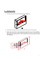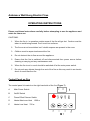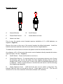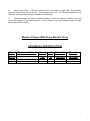
1
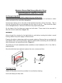
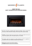
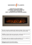
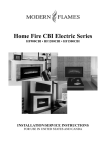
Ambiance Wall Hung Electric Fires
Packing Check List
Package 1
1 x Electric Fire
1 x Glass Face
1 x Remote Control Handset
2 x AAA Batteries
1 x Instructions Booklet
1 x Wall Fixing Plate
1 x Fasteners Package
Package 2
1 x Fire Face (Stone Face Models only)
INSTRUCTION BOOKLET MUST BE LEFT WITH THE USER
MODERN FLAMES
3423 EAST ATLANTA
PHOENIX, ARIZONA 85040
WWW.MODERNFLAMES.COM
Ambiance Wall Hung Electric Fires
INSTALLATION INSTRUCTIONS
This Electric Fire must be installed by a qualified, competent installer.
A.
Location
1.
The fire must not be in contact with any combustible materials.
2.
The heater, which is located at the base of the fire, must be a minimum of 16
inches away from any combustible material.
3.
It is important that the wall on to which the fire is to be installed is of sound
construction. All fasteners must be suitable for the type of wall, must be secure
to the wall and capable of taking the weight of the fire and the face.
4.
The fire must not be installed in an area where there is restricted air flow around
the fire.
5.
This appliance is for indoor installation but is ok to be installed outside in fully
covered installations free from damaging weather (rain snow etc.)
6.
The appliance must be kept away from any source of damp or moist conditions.
Avoid any close contact with water.
7.
If there is any doubt regarding the suitability of the installation site contact your
supplier.
8.
These fires produce heat consequently it is important to ensure that a suitable
wall covering is selected behind and around the appliance. Typical wood frame
drywall construction is suitable.
2
B.
Installation
PLEASE READ THROUGH THE INSTALLATION INSTRUCTIONS BEFORE
BEGINNING THE INSTALLATION.
Figure 1
1.
Select the position of the fire on the wall to which it is to be mounted. Draw a
level horizontal line on the wall at the required height. This line will correspond
to the top of the appliance so it is important to allow for the extra height of the
fire front.
2.
Mark the center line of the fire on to the horizontal line
3.
Place the Installation Plate supplied to the horizontal line and line up the center
“V” cut out with the center line. See Figure 1.
4.
DRYWALL INSTALLATION) Install screws provided into studs at 4 outside
corner screw holes. If studs are not present, install self drilling hollow wall
anchors provided at the 4 outside corners and find wood studs with at least 4
more screws on the mounting plate. (2 high and 2 low) Holes are offset to allow
finding wood studs at normal spacing. Attach more screws into wood on 95”
model.
5.
MASONRY INSTALLATION) If the wall is of a sound masonry construction the
attaching holes should be drilled with an 5/16” mm masonry drill. First secure the
4 outside corners. Use the masonry anchors and screws provided. Double
check that a firm solid attachement is achieved or add additional anchors as
required.
6.
If a firm attachement cannot be achieved it may be necessary to install extra
support to the framing. It is most important that the mounting plate are firm and
solid and that the structure is capable of taking the load.
3
7.
The mounting plate has four location pins, one at each corner of the plate. See
Figure 1.
8.
Lift the fire and place the keyhole slots situated on the back of the fire (Figure 2)
to the location pins on the mounting plate. A gentle downward pressure should
be applied. Make sure all of the pins have been located into the top section of
each keyhole fixing slot. (See Figures 3 & 4)
4
C.
Electrical Work
THIS PRODUCT MUST BE GROUNDED
1. A standard electrical outlet must be close to the fire. If the electric outlet is
required to be concealed, it can be located above or on the right hand side of the
fire and behind the face.
2. DO NOT INSTALL THE FIRE WHERE THE HEATER IS DIRECTLY ABOVE THE
PLUG SOCKET. The heat outlet is located in the center at the base of the fire.
3. If the power supply cable becomes damaged in any manner it MUST be replaced.
4. DO NOT connect the appliance to an extension cord or cable. This can create an
unsafe condition.
5. The fire must not be modified from the manufacturer’s specification in any way and
the appliance must only be used for the purpose recommended by the
manufacturer.
6. If the fire shows any signs of damage it is important that it is examined by a
qualified person.
7. Please observe these instructions as failure to do so may result in electric shock or
other injury.
8. Always ensure that all electrical work complies with the relevant Building Codes.
All electrical work should be carried out by a qualified electrician.
9. If in any doubt contact your supplier or a qualified electrician.
5
D.
Attaching The Face
1. On each side of the fire are two locating studs (Figure 5).
2. On the back of the face there are two brackets which hook over these studs.
3. Lift the face up to the fire. Two people may be required to carry out this installation.
Then lower the face into place so that the brackets on the rear of the face locate
either side of the studs on the fire. Once in place firmly screw into place the locking
bolt. (Figure 6)
6
Ambiance Wall Hung Electric Fires
OPERATING INSTRUCTIONS
Please read these instructions carefully before attempting to use the appliance and
retain for future use.
CAUTIONS:
1.
When the fire is in operation certain areas of the fire will get hot. Caution must be
taken to avoid being burned. Don’t touch hot surfaces.
2.
The fire must not be switched on if volatile vapours are present in the room
3.
Children must be supervised around the fire.
4.
Do not obstruct the air flow around the appliance.
5.
Ensure that the fire is switched off and disconnected from power source before
cleaning or carrying out any maintenance work.
6.
When the fire is not in use it should be switched off at the main power switch.
7.
Do not push any objects through the vent of the fire as this may result in an electric
shock or could cause a fire.
Control Panel on Fire
The control panel is located on the right hand side of the fire (Figure 7).
I
A
Main Power Switch
B
On/Off Switch
C
Flame Effect Dimmer Switch
D
Heater Maximum Heat
E
Heater Low Heat
O
1500 w
750 w
7
Remote Control
L
O
W
DIMMER
A
Infrared Window
C
Flame Effect Dimmer
E
Heater Low Heat
B
D
H
I
G
H
ON/OF
On/Off Switch
Heater Maximum Heat
Prior to use, the remote control handset requires installation of 2 x AAA batteries, as
supplied. (Figure 8)
Remove the cover on the rear of the remote handset by sliding backwards. Install the
batteries as shown and then slide the cover back into the original position.
To enable the remote control to function the power to the fire must be switched on.
At a distance of 5 to 6 feet, point the remote control handset directly towards the bottom
right hand side of the fire. (Figure 9)
B
On/Off Switch
Press on/off switch to turn fire on.
C
Flame Effect Dimmer ~ To operate press once to commence dimming cycle. During
the dimming cycle the fire will slowly dim then brighten allowing user to choose
suitable level. Press a second time to stop cycle when the desired brightness level
is obtained. Failure to press dimmer a second time will result in the fire dimming
then brightening repeatedly.
D
Heater Maximum Heat
(1500 W) Press this once to switch to high heat. The
indicator light will come on as well as the fan. Press again to turn off. (The fan will
continue to run for a few moments until sensors indicate cool condition)
8
E
Heater Low Heat
(750 w) Press this once to switch to high heat. The indicator
light will come on as well as the fan. Press again to turn off. (The fan will continue to run
for a few moments until sensors indicate cool condition)
F
Indicator Lamps will verify current condition. If you are unsure if heat is on or off
check the lamps on the control panel. If the function is on the indicator lamp will light
above the function switch.
Modern Flames Wall Hung Electric Fires
TECHNICAL SPECIFICATION
Model
Measures WxHx D
Weight
volts
Watts L/H
AL 38
AL- 56 56 ¼” x 27 ¾”x5 ¾”
AL-95
95
7*lbs
95 lbs
150*lb
120
750/1500
750/1500
750/1500
120
Remote
Control
included
included
included
9
Modern Flame Wall Hung Electric Fires
MAINTENANCE INSTRUCTIONS
To Change A Light Bulb
Disconnect power supply before beginning any maintenance.
Light bulbs need to be replaced when you notice a dark section of the flame or when
clarity and detail of the coal effect disappears.
Unscrew the locking nut on the side of the brackets and then remove the face. This is
done by lifting the face up and swinging the face clear of the fire. Care should be taken
not to damage the face. Removal of the face may require two people.
On the base of the fire there are screws on both sides. These need to be removed to
allow the cover to slide down.(Figure 10).
WARNING
Allow at least five minutes for the light bulbs to cool before touching the bulbs to avoid
burning. Make sure power supply is disconnected.
Examine the bulbs to determine which one needs replacing. Remove the non working bulb
and replace with a new long life bulb. Hold the socket while unscrewing the old bulb and
while screwing in the replacement bulb. (Figure 11)
The bulbs are 40 watt candelabra bulbs available at most hardware or Do it Your Self or
Lighting stores.
Once the bulb has been replaced, replace the cover, screws and face.
Cleaning the Fire
Switch off the power to the fire and allow it to cool before cleaning.
Use a soft damp (not wet) cloth.
10
WARRANTY
In the unlikely event of a problem occurring due to a manufacturing fault within 24 months
from the date of purchase of the appliance it will be repaired or replaced free of charge.
Repair or replacement is at the option of Modern Flames.
Defects must be brought to the attention of Modern Flames Technical Service Department
by contacting Modern Flames at (602) 268-9353 or 3423 E. Atlanta Ave, Phoenix, AZ
85040. Please have proof of purchase, catalogue/model and serial numbers available
when calling. Limited warranty requires a proof of purchase of the product.
What this limited warranty does not cover
This warranty does not cover consumable items such as the bulbs and fuses which have a
limited lifespan.
This limited warranty does not apply to products that have been repaired (except by
Modern Flames or its authorized service representatives) or otherwise altered. This
warranty does further not apply to defects resulting from misuse, abuse, accident, neglect,
incorrect installation, water damage, improper maintenance or handling, or operation with
an incorrect power source.
11