1
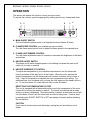
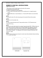
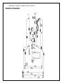
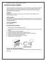
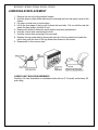
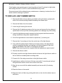
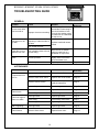
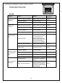
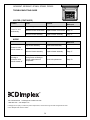
PARTS & SERVICE MANUAL
FOR THE 26” FIREPLACE
MODEL NUMBER:
BF5000NT
BF5000
EF2604
SF2603
DF2603
7400520000R03
TABLE OF CONTENTS
Table of Contents OPERATION .............................................................................................................................................. 2 EXPLODED DIAGRAM ........................................................................................................................... 4 WIRING DIAGRAM.................................................................................................................................. 5 REPLACEMENT PARTS .......................................................................................................................... 6 UPPER BULB REPLACEMENT .............................................................................................................. 7 LOWER BULB REPLACEMENT............................................................................................................. 8 TO REPLACE MAIN ON/OFF SWITCH ................................................................................................. 9 TO REPLACE LIGHT DIMMER SWITCH ............................................................................................ 10 TO REPLACE FLAME SPEED CONTROL SWITCH .......................................................................... 11 TO REPLACE FLAME MOTOR/FLAME ROD .................................................................................... 12 TO REPLACE HEATER ON/OFF SWITCH .......................................................................................... 14 TO REPLACE HEATER THERMOSTAT CONTROL .......................................................................... 15 TO REPLACE HEATER ASSEMBLY ................................................................................................... 16 TO REPLACE THE CORD SET ............................................................................................................. 17 TROUBLESHOOTING GUIDE .............................................................................................................. 18 1
BF5000NT, BF5000, EF2604, SF2603, DF2603
OPERATION
This section will explain the function of each convent control.
To access the controls, open the upper grill by pulling near the top, forward and down.
D
E
B
C
A
A. MAIN ON/OFF SWITCH
The on/off switch supplies power to all fireplace functions (heater & flame).
B. FLAME SPEED CONTROL (not available on some models)
Turn the flame speed control knob to adjust the flame speed to the desired level.
C. FLAME LIGHT DIMMER CONTROL
Turn the flame brightness control to increase or decrease the brightness of the flame
and embers.
D. HEATER ON/OFF SWITCH
The heater on/off switch supplies power to the heating unit when the main on/off
switch (A) is in the on position.
E. HEATER THERMOSTAT CONTROL
To adjust the temperature to your individual requirements, turn the thermostat
control clockwise all the way to turn in the heater. When the room reaches the
desired temperature, turn the thermostat knob counter clockwise until you hear a
click. Leave in this position to maintain the room temperature at its setting. For
additional heat, turn clockwise until you hear the click again and the heater will turn
on. To turn the heater off, rotate the knob fully counter clockwise.
RESETTING THE TEMPERATURE CUTOFF
This unit is equipped with a thermostat which controls the temperature of the room.
It does this by turning the heater on and off. The heater is protected with a safety
device to prevent overheating. Should the heater overheat, an automatic cut out will
turn the heater off and it will not come back on without being reset. It can be reset
by switching the ON/OFF SWITCH to OFF and waiting 5 minutes before switching
the unit back on.
CAUTION
If you need to continuously reset the heater, unplug the unit and call your local
dealer.
2
BF5000NT, BF5000, EF2604, SF2603, DF2603
REMOTE CONTROL INSTRUCTIONS
(Optional Accessory)
1. Plug firebox into the outlet located on the side of the receiver.
2. Plug receiver into the wall outlet.
3. Install a 9 volt battery into the transmitter.
4. Turn the firebox main power switch to the on position prior to using the remote
control.
5. Push the ON button to turn the firebox on. Push the OFF button to turn the firebox
OFF.
NOTE
To prevent the risk of fire, the stove plug must be inserted fully into the receiver
NOTE
For indoor use in dry areas only
NOTE
For use on electrical devices with 15 amp resistive load or 1/3 HP inductive load
120 VOLT AC only
NOTE
The remote control and receiver has a range of approximately 50ft. (15.25m) it does not
have to be pointed at the fireplace and can pass through most obstacles (including
walls). The remote control and receiver use one of 243 independent frequencies.
When replacing the remote control or the receiver they must be replaced as a set to
ensure proper operation. The frequency of the remote is located on the back of the
remote on a label.
NOTE
ON/OFF Remote Control may be used to control most other electrical devices including
T.V.’s, stereos and lamps.
TRANSMITTER
RECEIVER
3
BF5000NT, BF5000, EF2604, SF2603, DF2603
EXPLODED DIAGRAM
5
7
7
7
4
15
18
6
8
14
2
3
16
1
13
10
10
11
9
6
4
BF5000NT, BF5000, EF2604, SF2603, DF2603
WIRING DIAGRAM
5
BF5000NT, BF5000, EF2604, SF2603, DF2603
REPLACEMENT PARTS
REPLACEMENT PART
BF5000
1. Front Glass, Tempered
Bronze
2. Partially Reflective Glass
BF5000NT
BF5000NTRH
SF2603
DF2603
6900100400RP
6900100200RP
3. Log Set
4. On/Off Switch
EF2604
5900060300RP
0437960100RP
2800070200RP (MOD 0-C)
28000210100RP (MOD D)
2800070200RP (MOD E)
5. Heater On/Off Switch
2800070200RP (MOD 0-C)
28000210100RP (MOD D)
2800070200RP (MOD E)
2800210100RP
2800210100RP
6. Thermostat
2300150100RP
7. Control Knob
8800000300RP
8. Heater Assembly
2200490900RP
9. Grill Louvered Assembly
1006720159RP
2800070200RP
10.Light Bulb Holder
4200121000RP
11.Flicker Motor
3000240200KIT
12.Flicker Rod Assembly
6900190400RP
13.Power Cord
4100040200RP
14.Speed Control
3000240100RP
15.Light Dimmer
3000250100RP
16.Heyco Strain Relief
8500260003RP
2800071100RP
0437970100RP
17.Flame Panel
3000380200RP
(Added MOD
C)
18.Remote Control Receiver
19.Terminal Block
4000070100RP
3000370500RP
(Added MOD C)
20.Remote Control Transmitter
21.Foot
8800090100RP
6
BF5000NT, BF5000, EF2604, SF2603, DF2603
UPPER BULB REPLACEMENT
Light bulbs need to be replaced when you notice a dark section in the flame or when the
clarity and detail of the log exterior disappears. There are two bulbs at the top of the
opening that illuminates the log set exterior and four bulbs under the log set which
generate the flames and embers.
WARNING
Allow at least 10 minutes for light bulbs to cool off before touching bulbs to avoid
accidental burning of skin.
HELPFUL HINTS
It is a good idea to replace all light bulbs at one time if they are close to the end of their
rated life. Group replacement will reduce the number of times you need to open the unit
to replace light bulbs.
TOOL REQUIREMENTS
Slot screwdriver
UPPER BULB REPLACEMENT
1. Remove the trim by pulling straight forward.
2. Hold the glass in place while removing the retaining clip from the upper center of the
firebox.
3. Lift glass out and store in a safe place.
4. Locate the two upper bulbs inside the firebox at the top.
5. Examine the bulbs to determine which bulb(s) require(s) replacement.
6. Hold the socket while unscrewing the bulb.
7. Hold the socket while screwing in the new bulb.
8. Reassemble in the reverse order.
UPPER LIGHT BULB REQUIREMENTS
Quantity of 2 clear chandelier or candelabra bulbs with an E-12 (small) socket base, 15
watt rating.
7
BF5000NT, BF5000, EF2604, SF2603, DF2603
LOWER BULB REPLACEMENT
1. Remove the trim by pulling straight forward.
2. Hold the glass in place while removing the retaining clip from the upper center of the
firebox.
3. Lift glass out and store in a safe place.
4. Lift up the front edge of the log until it clears the front tabs. Pull out until the rear tab
clears the back ledge, and then lift out.
5. Examine the bulbs to determine which bulb(s) require(s) replacement.
6. Hold the socket while unscrewing the bulb.
7. Hold the socket while screwing in the new bulb.
8. Replace the log ember bed by placing the back lip of the log ember bed under the
mirror then push the front of the log ember bed down into the recess.
9. Reassemble in the reverse order.
LOWER LIGHT BULB REQUIREMENTS
Quantity of 4 clear chandelier or candelabra bulbs with an E-12 (small) socket base, 60
watt rating.
8
BF5000NT, BF5000, EF2604, SF2603, DF2603
If the fireplace was operating prior to servicing allow at least 10 minutes for light bulbs
and heating element to cool off to avoid accidental burning of skin.
Disconnect power before attempting any maintenance or cleaning to reduce the risk of
electric shock or damage to persons.
TO REPLACE MAIN ON/OFF SWITCH
1. Remove the firebox trim by placing your hand on the grill section, grasping the sides
of the trim and pulling outwards releasing the retainer clips.
2. Remove the firebox from the mantel.
3. Lower the grill covering the controls.
4. Remove the (4) retaining screws on the top cover and remove the top, placing it
upside down on the top of the unit being careful not to damage any of the wiring.
5. Locate the main on/off switch mounted on the top panel and disconnect the wiring
clips and connections noting their original locations.
6. Depress the retainer clips on the rear of the switch and push the switch out of the
rear cover.
7. Properly orient the new switch and connect all of the wiring clips and connections.
8. Align the top cover with the cabinet assembly and secure with (4) retaining screws.
9. Place the firebox in the mantel.
10. Place trim back on firebox by pushing ball studs on trim into the retainer clips on the
firebox.
9
BF5000NT, BF5000, EF2604, SF2603, DF2603
If the fireplace was operating prior to servicing allow at least 10 minutes for light bulbs
and heating element to cool off to avoid accidental burning of skin.
Disconnect power before attempting any maintenance or cleaning to reduce the risk of
electric shock or damage to persons.
TO REPLACE LIGHT DIMMER SWITCH
1. Remove the firebox trim by placing your hand on the grill section, grasping the
sides of the trim and pulling outwards releasing the retainer clips.
2. Remove the firebox from the mantel.
3. Lower the grill covering the controls.
4. Remove the (4) retaining screws on the top cover and remove the top, placing it
upside down on the top of the unit being careful not to damage any of the wiring.
5. Locate the light dimmer switch mounted on the top panel and disconnect the
wiring connections noting their original locations.
6. Pull off the light dimmer control knob to expose the (1) mounting nut.
7. Remove the (1) mounting nut from the control arm of the light dimmer.
8. From under the panel, break off the four mounting studs on the light dimmer
switch by grasping with pliers and twisting on the protruding part of the stud,
push the remainder of the studs out through the top panel.
NOTE: New mounting studs are supplied with the replacement speed control.
9. Remove the dimmer switch
10. Properly orient the new light dimmer switch and secure the light dimmer switch to
the unit with the included plastic mounting studs.
11. Connect all of the wiring connections to the light dimmer switch.
12. Install dimmer switch to the front of the top cover with (1) mounting nut and put
the light dimmer switch control knob on the control arm.
13. Align the top cover with the cabinet assembly and secure with (4) retaining
screws.
14. Place the firebox in the mantel.
15. Place trim back on firebox by pushing ball studs on trim into the retainer clips on
the firebox.
10
BF5000NT, BF5000, EF2604, SF2603, DF2603
If the fireplace was operating prior to servicing allow at least 10 minutes for light bulbs
and heating element to cool off to avoid accidental burning of skin.
Disconnect power before attempting any maintenance or cleaning to reduce the risk of
electric shock or damage to persons.
TO REPLACE FLAME SPEED CONTROL SWITCH
1. Remove the firebox trim by placing your hand on the grill section, grasping the
sides of the trim and pulling outwards releasing the retainer clips.
2. Remove the firebox from the mantel.
3. Lower the grill covering the controls.
4. Remove the (4) retaining screws on the top cover and remove the top, placing it
upside down on the top of the unit being careful not to damage any of the wiring.
5. Locate the light dimmer switch mounted on the top panel and disconnect the
wiring connections noting their original locations.
6. Pull off the light dimmer control knob to expose the (1) mounting nut.
7. Remove the (1) mounting nut from the control arm of the light dimmer.
8. From under the panel, break off the four mounting studs on the light dimmer
switch by grasping with pliers and twisting on the protruding part of the stud,
push the remainder of the studs out through the top panel.
NOTE: New mounting studs are supplied with the replacement speed control.
9. Remove the dimmer switch
10. Properly orient the new light dimmer switch and secure the light dimmer switch to
the unit with the included plastic mounting studs.
11. Connect all of the wiring connections to the light dimmer switch.
12. Install dimmer switch to the front of the top cover with (1) mounting nut and put
the light dimmer switch control knob on the control arm.
13. Align the top cover with the cabinet assembly and secure with (4) retaining
screws.
14. Place the firebox in the mantel.
15. Place trim back on firebox by pushing ball studs on trim into the retainer clips on
the firebox.
11
BF5000NT, BF5000, EF2604, SF2603, DF2603
If the fireplace was operating prior to servicing allow at least 10 minutes for light bulbs
and heating element to cool off to avoid accidental burning of skin.
Disconnect power before attempting any maintenance or cleaning to reduce the risk of
electric shock or damage to persons.
TO REPLACE FLAME MOTOR/FLAME ROD
1. Remove the firebox trim by grasping both sides of the trim and pulling straight up.
2. Remove the front glass retaining clip.
3. Remove the front glass and set aside.
4. Remove the log set by lifting up the front edge of the log until it clears the front tabs.
Pull out until the rear tab clears the back ledge, then lift out.
5. Remove the firebox from the mantel and unplug.
6. Remove (2) screws from the bottom panel located on the back assembly.
7. Lay unit on back.
8. Remove the (2) remaining screws from the bottom panel located on the left and right
sides.
9. Remove the bottom panel and set aside.
10. Remove (1) screw from the motor bracket located in the flame panel.
11. Remove flicker motor assembly by pulling flicker motor towards you and by
removing bracket from slot located in back panel.
12. Remove (2) screws securing the flicker motor to the flicker motor bracket.
13. Cut the flicker motor wires close to the flicker motor end with wire cutters.
14. Remove reflector rod from flicker motor by bending the rod down 90º and cutting the
reflector spring with wire cutters. DO NOT TAKE THE LEFTOVER SPRING OFF
OF THE END OF THE REFLECTOR ROD
15. Discard old flicker motor.
16. Pick up the 1 ½” rubber sleeve and locate over remaining spring on reflector rod.
ENSURE TO LOCATE THE LARGE OPENING OF THE BLACK CYLINDER OVER
THE REMAINING SPRING OF REFLECTOR ROD.
17. Pick up new flicker motor and cut wire leads to 3 ½” long with wire cutters.
12
BF5000NT, BF5000, EF2604, SF2603, DF2603
18. Secure new flicker motor to the existing reflector rod. Ensure the flicker motor
bracket is in between the motor and reflector rod.
19. Pick up wire connector and place (1) yellow wire into each terminal.
(total of 2 yellow wires)
20. Secure wire connector by crimping the 3M symbol with slip joint pliers.
21. Pull on end of wires to ensure a strong connection.
22. Repeat the process for the (4) remaining wires. (red, blue, orange, grey)
ENSURE THAT ALL CONNECTORS HAVE THE SAME WIRE COLOURS
23. Reassemble in the reverse order.
13
BF5000NT, BF5000, EF2604, SF2603, DF2603
If the fireplace was operating prior to servicing allow at least 10 minutes for light bulbs
and heating element to cool off to avoid accidental burning of skin.
Disconnect power before attempting any maintenance or cleaning to reduce the risk of
electric shock or damage to persons.
TO REPLACE HEATER ON/OFF SWITCH
1. Remove the firebox trim by grasping both sides of the trim and pulling straight up.
2. Remove the firebox from the mantel.
3. Remove the (4) retaining screws on the top cover and remove the top, placing it
upside down on the top of the unit being careful not to damage any of the wiring.
4. Locate the heater on/off switch mounted on the top panel and disconnect the
wiring clips and connections noting their original locations.
5. Depress the retainer clips on the rear of the switch and push the switch out of the
rear cover.
6. Properly orient the new switch and connect all of the wiring clips and
connections.
7. Align the top cover with the cabinet assembly and secure with (4) retaining
screws.
8. Place the firebox in the mantel.
9. Place trim back on firebox by opening grill, grasping both sides of trim, and hook
the trim down into the trim slots.
NOTE: The trim slots are located on the front surface of the firebox.
10. Close the grill.
14
BF5000NT, BF5000, EF2604, SF2603, DF2603
If the fireplace was operating prior to servicing allow at least 10 minutes for light bulbs
and heating element to cool off to avoid accidental burning of skin.
Disconnect power before attempting any maintenance or cleaning to reduce the risk of
electric shock or damage to persons.
TO REPLACE HEATER THERMOSTAT CONTROL
1. Remove the firebox trim by grasping both sides of the trim and pulling straight up.
2. Remove the firebox from the mantel.
3. Remove the (4) retaining screws on the top cover and remove the top, placing it
upside down on the top of the unit being careful not to damage any of the wiring.
4. Locate the thermostat control mounted on the top panel and disconnect the
wiring clips and connections noting their original locations.
5. Pull off the thermostat control knob to expose the mounting screws.
6. Remove the mounting screws and remove the heater thermostat control.
7. Properly orient the new heater thermostat control and connect all of the wiring
connections.
8. Reassemble in the reverse order as above.
15
BF5000NT, BF5000, EF2604, SF2603, DF2603
If the fireplace was operating prior to servicing allow at least 10 minutes for light bulbs
and heating element to cool off to avoid accidental burning of skin.
Disconnect power before attempting any maintenance or cleaning to reduce the risk of
electric shock or damage to persons.
TO REPLACE HEATER ASSEMBLY
1. Remove the firebox trim by grasping both sides of the trim and pulling straight up.
2. Remove the firebox from the mantel.
3. Remove the (4) retaining screws on the top cover and remove the top, placing it
upside down on the top of the unit being careful not to damage any of the wiring.
4. Locate the heater assembly mounted on the top panel and disconnect the wiring
clips and connections noting their original locations.
5. Turn the top over, remove the heater mounting screws and remove the heater
assembly.
6. Properly orient the new heater assembly and connect all of the wiring
connections.
7. Reassemble in the reverse order as above.
16
BF5000NT, BF5000, EF2604, SF2603, DF2603
If the fireplace was operating prior to servicing allow at least 10 minutes for light bulbs
and heating element to cool off to avoid accidental burning of skin.
Disconnect power before attempting any maintenance or cleaning to reduce the risk of
electric shock or damage to persons.
TO REPLACE THE CORD SET
1. Remove the firebox trim by grasping both sides of the trim and pulling straight up.
2. Remove the firebox from the mantel.
3. Remove the (4) retaining screws on the top cover and remove the top, placing it
upside down on the top of the unit being careful not to damage any of the wiring.
4. Locate and disconnect the power cord wiring connections noting their original
locations.
5. With needle nose pliers grasp the power cord strain relief grommet from inside the
rear of the heater panel and push while twisting to remove.
6. Pull the power cord out through the hole in the rear of the top heater pan.
7. Install the new power cord through the hole in the rear cover and connect all of the
wiring connections in their original locations.
8. Install the power cord strain relief grommet on the replacement power cord and
insert into the mounting hole in the rear of the top heater pan.
WARNING: Ensure wires do not come in contact with moving parts by securing
wires in wiring tie wraps.
9. Reassemble in the reverse order as above.
17
BF5000NT, BF5000NT, EF2604, SF2603, DF2603
TROUBLESHOOTING GUIDE
GENERAL
Problem
Cause
Solution
Improper circuit current rating
Additional appliances may
exceed the current rating of
the circuit breaker or fuse.
Plug unit into another outlet
or install unit on a dedicated
15 amp circuit
Remote control has a similar
frequency to other remotes in
the area
Radio frequency disturbance
from outside sources
Replace hand held remote
control
Lights dim in room
while the unit is on
Unit is drawing close to circuit
current rating
Move the unit to another
outlet or install unit on a
dedicated 15 amp circuit
Power cord gets
warm
Normal operation
Circuit breaker trips
or fuse blows when
unit is turned on
Unit turns on or off
by itself
Service Manual
Reference
Defective power cord
The power cord may get
slightly warm to the touch
when the heater is on
Replace power cord
Cause
Solution
Improper operation
Refer to User’s Guide
Defective main on/off switch
Replace main on/off switch
Page 10
Defective remote control
Install new battery into the
handheld transmitter
Page 2
Loose wiring
Check wiring connections
Page 7
Defective flame motor
Replace flame motor
Page 13
Loose wiring
Check wiring connections
Page 7
Burnt light bulbs
Replace light bulbs
Page 8
Loose wiring
Check wiring connections
Page 7
Defective light harness
Replace light harness
Log set dim, ember
bed not glowing
Burnt light bulbs
Replace light bulbs
Page 8
Flame Shutter
Defective flame motor
Replace flame motor
Page 13
Page 18
APPEARANCE
Problem
Fireplace does not
turn on
Flame frozen
Flame not bright or
flame not visible
18
Service Manual
Reference
BF5000NT, BF5000NT, EF2604, SF2603, DF2603
TROUBLESHOOTING GUIDE
HEATER
Problem
Heater is not
turning off
Heater is not
turning on
Cause
Solution
Service Manual
Reference
Defective heater on/off switch
Replace heater on/off switch
Page 14
Improper operation
See User’s Guide
Loose wiring
Trace wiring in unit
Page 7
Defective heater on/off switch
Replace heater on/off switch
Page 14
Defective heater assembly
Replace heater assembly
Page 17
Improper operation
See User’s Guide
Loose wiring
Trace wiring in unit
Normal operation
Normal operation is when
the heater emits an odor for
a brief period after the
heater is initially turned on.
The heater is burning off any
dust accumulated during
manufacturing or operation.
Defective heater assembly
Replace heater assembly
Page 17
Loose wiring
Trace wiring in unit
Page 7
Improper operation
See User’s Guide
Defective thermostat
Replace thermostat
Page 15
Loose wiring
Trace wiring in unit
Page 7
Defective heater assembly
Replace heater assembly
Small glowing sections of
the element are considered
normal.
If larger glowing sections are
causing the heater to trip the
thermal cut out, unplug unit,
discontinue use and replace
heater assembly
Page 17
Heater emits an
odor
Heater fan turns on
but heater lacks
heat
Normal operation
Heating element is
glowing red
Defective heater assembly
19
Page 7
Page 17
BF5000NT, BF5000NT, EF2604, SF2603, DF2603
TROUBLESHOOTING GUIDE
HEATER (CONTINUED)
Problem
Heater fan runs
continuously
Cause
Solution
Service Manual
Reference
Loose wiring
Trace wiring in unit
Page 7
Defective heater on/off switch
Replace heater on/off switch
Page 14
Defective heater assembly
Replace heater assembly
Page 17
Cause
Solution
Service Manual
Reference
Dirty blower assembly
Clean blower assembly
Defective blower assembly
Replace heater assembly
Page 17
Moving flame rod hitting or
rubbing against internal
components
Flame rod replacement
Page 13
Defective flame motor
Replace flame motor
Page 13
NOISE
Problem
Excessive noise
with the heater on
Grinding or
excessive noise
with the heater off
1367 Industrial Road Cambridge ON Canada N1R 7G8
1-888-346-7539 www.dimplex.com
In keeping with our policy of continuous product improvement, we reserve the right to make changes without notice.
© 2011 Dimplex North America Limited
20