1
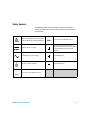
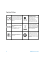
Agilent U8030A Series
Triple Output DC Power
Supply
Service Guide
Agilent Technologies
Notices
© Agilent Technologies, Inc. 2012
Warranty
No part of this manual may be reproduced in
any form or by any means (including electronic storage and retrieval or translation
into a foreign language) without prior agreement and written consent from Agilent
Technologies, Inc. as governed by United
States and international copyright laws.
The material contained in this document is
provided “as is,” and is subject to change,
without notice, in future editions. Further,
to the maximum extent permitted by the
applicable law, Agilent disclaims all warranties, either express or implied, with
regard to this manual and any information
contained herein, including but not limited
to the implied warranties of merchantability and fitness for a particular purpose.
Agilent shall not be liable for errors or for
incidental or consequential damages in
connection with the furnishing, use, or
performance of this document or of any
information contained herein. Should Agilent and the user have a separate written
agreement with warranty terms covering
the material in this document that conflict
with these terms, the warranty terms in
the separate agreement shall control.
Manual Part Number
U8031-90013
Edition
First Edition, March 20, 2012
Agilent Technologies, Inc.
5301, Stevens Creek Blvd.
Santa Clara, CA 95051 USA
Technology Licenses
The hardware and or software described in
this document are furnished under a license
and may be used or copied only in accordance with the terms of such license.
Restricted Rights Legend
U.S. Government Restricted Rights. Software and technical data rights granted to
the federal government include only those
rights customarily provided to end user customers. Agilent provides this customary
commercial license in Software and technical data pursuant to FAR 12.211 (Technical
Data) and 12.212 (Computer Software) and,
for the Department of Defense, DFARS
252.227-7015 (Technical Data - Commercial
Items) and DFARS 227.7202-3 (Rights in
Commercial Computer Software or Computer Software Documentation).
II
Safety Notices
CAUTION
A CAUTION notice denotes a hazard. It calls attention to an operating procedure, practice, or the likes
of that, if not correctly performed
or adhered to, could result in damage to the product or loss of important data. Do not proceed beyond a
CAUTION notice until the indicated
conditions are fully understood and
met.
WA R N I N G
A WARNING notice denotes a
hazard. It calls attention to an
operating procedure, practice, or
the likes of that, if not correctly
performed or adhered to, could
result in personal injury or death.
Do not proceed beyond a WARNING notice until the indicated
conditions are fully understood
and met.
U8030A Series Service Guide
Safety Symbols
The following symbols on the instrument and in the documentation
indicate precautions which must be taken to maintain safe operation of
the instrument.
Caution, risk of danger (refer to this manual
for specific Warning or Caution information)
In position of a bi-stable push control
DC (Direct current or voltage)
Terminal is at earth potential. Used for
measurement and control circuits designed to
be operated with one terminal at earth
potential.
AC (Alternating current or voltage)
Positive binding post
Protective conductor terminal
Negative binding post
Out position of a bi-stable push control
U8030A Series Service Guide
III
Safety Considerations
Read the information below before using this instrument.
The following general safety precautions must be observed during all
phases of operation, service, and repair of this instrument. Failure to
comply with these precautions or with specific warnings elsewhere in this
manual violates safety standards for design, manufacture, and intended
use of the instrument. Agilent Technologies assumes no liability for the
customer’s failure to comply with these requirements.
CAUTION
• Use the device with the cables provided with the shipment.
• If the device is used in a manner not specified by the manufacturer,
the device protection may be impaired.
• Always use dry cloth to clean the device. Do not use ethyl alcohol or
any other volatile liquid to clean the device.
• Do not permit any blockage of the ventilation holes of the device.
WA R N I N G
• Do not use the device if it appears damaged or defective.
• Do not operate the device around flammable gases or fumes,
vapor, or wet environments.
• Observe all markings on the device before connecting any wiring
to the device.
• Turn off the output of the power supply before connecting to the
output terminals.
• When servicing the device, use only the specified replacement
parts.
• Do not install substitute parts or perform any unauthorized
modification to the device.
• Do not operate the device with the cover removed or loosened.
• Use only the power adapter provided by the manufacturer to avoid
any unexpected hazards.
IV
U8030A Series Service Guide
Environmental Conditions
This instrument is designed for indoor use and in an area with low
condensation. The table below shows the general environmental
requirements for this instrument.
NOTE
Environmental condition
Requirements
Operating temperature
0 °C to 40 °C
Storage temperature
–40 °C to 70 °C
Humidity
15% RH (relative humidity) to 85% RH at 40 °C
(non-condensing)
Altitude
Up to 2000 meters
Installation category
Installation Category II
Pollution degree
Pollution Degree 2
The U8030A Series Triple Output DC Power Supply complies with the following
safety and EMC requirements:
•
•
•
•
•
•
•
U8030A Series Service Guide
IEC61326-1:2005 / EN61326-1:2006
CISPR 11:2003/ EN55011:2007
Canada: ICES/NMB-001: Issue 4, June 2006
Australia / New Zealand: AS/NZS CISPR11:2004
IEC 61010-1:2001 / EN 61010-1:2001 (2nd Edition)
Canada: CAN/CSA-C22.2 No. 61010-1-04
USA: ANSI/UL 61010-1:2004
V
Regulatory Markings
VI
The CE mark is a registered trademark
of the European Community. This CE
mark shows that the product complies
with all the relevant European Legal
Directives.
The C-tick mark is a registered
trademark of the Spectrum
Management Agency of Australia. This
signifies compliance with
the Australia EMC Framework
regulations under the terms of the
Radio Communication Act of 1992.
ICES/NMB-001 indicates that this ISM
device complies with the Canadian
ICES-001.
Cet appareil ISM est confomre a la
norme NMB-001 du Canada.
This instrument complies with the
WEEE Directive (2002/96/EC) marking
requirement. This affixed product label
indicates that you must not discard
this electrical or electronic product in
domestic household waste.
The CSA mark is a registered
trademark of the Canadian Standards
Association.
This symbol indicates the time period
during which no hazardous or toxic
substance elements are expected to
leak or deteriorate during normal use.
Forty years is the expected useful life
of the product.
U8030A Series Service Guide
Waste Electrical and Electronic Equipment (WEEE) Directive 2002/96/EC
This instrument complies with the WEEE Directive (2002/96/EC) marking
requirement. This affixed product label indicates that you must not discard
this electrical or electronic product in domestic household waste.
Product Category:
With reference to the equipment types in the WEEE directive Annex 1, this
instrument is classified as a “Monitoring and Control Instrument” product.
The affixed product label is as shown below.
Do not dispose in domestic household waste.
To return this unwanted instrument, contact your nearest Agilent Service
Center, or visit
www.agilent.com/environment/product
for more information.
U8030A Series Service Guide
VII
Declaration of Conformity (DoC)
The Declaration of Conformity (DoC) for this instrument is available on the
Agilent website. You can search the DoC by its product model or
description at the web address below.
http://regulations.corporate.agilent.com/DoC/search.htm
NOTE
VIII
If you are unable to search for the respective DoC, please contact your
local Agilent representative.
U8030A Series Service Guide
Table of Contents
1
Calibration Procedures
Agilent Calibration Services 2
Calibration interval 2
Other recommendations for calibration
Recommended Test Equipment
Test Considerations
2
3
5
Measurement Techniques
6
Performance Verification Tests 10
Constant voltage (CV) verification
Constant current (CC) verification
10
17
Performance Test Record for U8031A
23
Performance Test Record for U8032A
26
Using the Front Panel for Adjustments 29
Calibration procedure 29
Restarting the calibration procedure 33
Toggling between channels and calibration modes
Exiting the calibration mode 34
List of Error Codes 35
System errors 35
Power channel errors
U8030A Series Service Guide
34
35
IX
2
Service and Maintenance
Troubleshooting
38
Line Voltage Conversion
Self-Test Procedure
39
40
Returning the Instrument for Service
Replaceable Parts 42
To order replaceable parts
41
43
Types of Service Available 44
Extended service contracts 44
Obtaining Repair Service (Worldwide)
X
45
U8030A Series Service Guide
List of Figures
Figure 1-1
Figure 1-2
Figure 1-3
Figure 1-4
Figure 1-5
Figure 1-6
Figure 2-1
U8030A Series Service Guide
Test setup (A) 6
Test setup (B) 6
Test setup (C) 7
Test setup (D) 8
Binding post side view 9
Graph of load transient response 17
Orientation of voltage selector for different voltage
selection 39
XI
THIS PAGE HAS BEEN INTENTIONALLY LEFT BLANK.
XII
U8030A Series Service Guide
List of Tables
Table 1-1
Table 1-2
Table 1-3
Table 1-4
Table 1-5
Table 1-6
Table 1-7
Table 2-1
Table 2-2
Table 2-3
U8030A Series Service Guide
Recommended test equipment 3
U8031A CV performance test record 23
U8031A CC performance test record 24
U8032A CV performance test record 26
U8032A CC performance test record 27
List of system error codes 35
List of power channel error codes 35
Operating checklist 38
Line voltage fuse rating indicator for
U8031A/U8032A 40
Replaceable parts for U8031A/U8032A 42
XIII
THIS PAGE HAS BEEN INTENTIONALLY LEFT BLANK.
XIV
U8030A Series Service Guide
U8030A Series Triple Output DC Power Supply
Service Guide
1
Calibration Procedures
Agilent Calibration Services 2
Calibration interval 2
Other recommendations for calibration 2
Recommended Test Equipment 3
Test Considerations 5
Measurement Techniques 6
Performance Verification Tests 10
Constant voltage (CV) verification 10
Constant current (CC) verification 17
Performance Test Record for U8031A 23
Performance Test Record for U8032A 26
Using the Front Panel for Adjustments 29
Calibration procedure 29
Restarting the calibration procedure 33
Toggling between channels and calibration modes 34
Exiting the calibration mode 34
List of Error Codes 35
This chapter contains procedures for verifying the
instrument performance, as well as procedures for making
adjustments (calibration) where necessary.
Agilent Technologies
1
1
Calibration Procedures
Agilent Calibration Services
Agilent Calibration Services
When your instrument is due for calibration, contact your
local Agilent Service Center for recalibration. See “Types of
Service Available” on page 44 for more information on the
various calibration services offered.
Calibration interval
The instrument should be calibrated on a regular interval
determined by the measurement accuracy requirements of
your application.
A one- year interval is adequate for most applications.
Accuracy specifications are warranted only if calibration is
performed at regular intervals. Accuracy specifications are
not warranted beyond the one- year calibration interval.
Agilent does not recommend extending calibration intervals
beyond two years for any application.
Other recommendations for calibration
Specifications are only guaranteed within the specified
period from the last calibration. Agilent recommends that
readjustment should always be performed at whatever
calibration interval you select. This will ensure that the
instrument remains within its specifications until the next
calibration. This calibration criterion provides the best
long- term stability.
During performance verification tests, only the performance
data is collected; these tests do not guarantee that the
instrument will remain within the specified limits. The tests
are only for identifying which functions need adjustment.
2
U8030A Series Service Guide
Calibration Procedures
Recommended Test Equipment
1
Recommended Test Equipment
The test equipment recommended for the performance
verification and adjustment procedures is listed below in
Table 1- 1. If the exact instrument is not available, substitute
with another calibration standard of equivalent accuracy.
Table 1-1 Recommended test equipment
Equipment
Requirement(s)
Digital multimeter
(DMM)
8½ digits resolution
Oscilloscope
• Sensitivity: 1 mV
• Bandwidth limit: 20 MHz
• Probe:
• 1:1 with RF tip
• 10:1 with RF tip for > 50 V
Differential
amplifier
• Bandwidth > 20 MHz
(bandwidth limit: 20 MHz)
• AC coupling
• Amplifier × 10
RMS volt meter
20 Hz to 20 MHz
50 Ω feed-through
termination
Used[1]
Recommended model
Purpose
Agilent 3458A
Measures accurate DC voltage
Agilent DSO8064A or
Infiniium equivalent
Displays transient response.
Displays ripple and noise
waveform.
PV
LeCroy DA1855A
Signal conditioning preamplifiers
PV
R&S URE3
Measures RMS noise
PV
-
Pomona
Loads termination to match
output impedance of the
differential amplifier
PV
AC/DC current
converter
-
Tektronix TCP305 and
Tektronix TCPA300
Converts current to voltage
PV
Electronic load
•
•
•
•
Voltage range: 60 Vdc
Current range: 6 A
Open and Short switches
Transient On/Off
Agilent 6060B
Measures load and line
regulations and transient
response time
PV
AC power source
Capable of supplying 90 Vac to
250 Vac
Agilent 6813B
Functions as variable voltage
transformer
PV
U8030A Series Service Guide
PV
C
3
1
Calibration Procedures
Recommended Test Equipment
Table 1-1 Recommended test equipment (continued)
Equipment
Requirement(s)
Resistive load (RL)
• 5 Ω/180 W (for U8031A)
• 20 Ω/180 W (for U8032A)
• 1.67 Ω/15 W (for 5 V Output 3)
Current monitoring
resistor (shunt)
(RM)
• 0.01 Ω ± 0.1%
• TCR less than 20 ppm/ºC
Recommended model
Purpose
Used[1]
-
Measures ripple and noise
PV
ISOTEK Co.
Model A-H
Current monitoring resistor
PV
C
[1] PV: Performance Verification, see page 10 for more information.
C: Calibration, see page 29 for more information.
4
U8030A Series Service Guide
Calibration Procedures
Test Considerations
1
Test Considerations
For optimum performance, all procedures should comply
with the following recommendations:
• Ensure that the calibration ambient temperature is stable
and is recommended at 23 °C ± 2 °C.
• Ensure that the ambient relative humidity is less than
80%.
• Allow a warm- up period of 1 hour by powering on the
power supply. During the warm- up period, set the power
supply to its maximum programmable voltage and current.
Then, enable the output.
• Keep the test setup connection cables as short as possible.
U8030A Series Service Guide
5
1
Calibration Procedures
Measurement Techniques
Measurement Techniques
Test setup
Most tests are performed at the front terminals as shown
below. Measure the DC voltage directly at the positive (+)
and negative (–) terminals on the front panel.
DC voltmeter
or scope
+
+
–
–
+
–
Electronic load or resistor
Figure 1-1 Test setup (A)
+
+
–
Current
shunt
DC voltmeter
–
+
–
Electronic load or resistor
Figure 1-2 Test setup (B)
6
U8030A Series Service Guide
Calibration Procedures
Measurement Techniques
+
1
–
Load
resistor
BNC
BNC
+
–
Differential amplifier output
BNC
50 Ω
termination
Input scope or
RMS voltmeter
Figure 1-3 Test setup (C)
U8030A Series Service Guide
7
1
Calibration Procedures
Measurement Techniques
+
–
Load
resistor
TCP305
BNC
TCPA300
BNC
AC/DC converter
50 Ω
termination
Differential amplifier output
BNC
50 Ω
termination
RMS voltmeter
Figure 1-4 Test setup (D)
Current monitoring resistor
To eliminate output current measurement error caused by
the voltage drops in the leads and connections, connect the
current monitoring resistor (RM) between the (–) output
terminal and the load as a four- terminal device. Connect the
current monitoring leads inside the load- lead connections
directly at the monitoring points on the resistor element.
8
U8030A Series Service Guide
Calibration Procedures
Measurement Techniques
1
General measurement techniques
To achieve best results when measuring load regulation, peak
to peak voltage, and transient response time of the power
supply, measuring devices must be connected through the
hole in the neck of the binding post at (A) while the load
resistor is plugged into the front of the output terminals at
(B). A measurement made across the load includes the
impedance of the leads to the load. The impedance of the
load leads can easily be several orders of magnitude greater
than the power supply impedance and thus invalidate the
measurement. To avoid mutual coupling effects, each
measuring device must be connected directly to the output
terminals by separate pairs of leads.
Output terminal
B
A
Figure 1-5 Binding post side view
Electronic load
Many of the test procedures require the use of a variable
load resistor capable of dissipating the required power.
Using a variable load resistor requires that switches should
be used to connect, disconnect, and short the load resistor.
An electronic load, if available, can be used in place of a
variable load resistor and switches. The electronic load is
considerably easier to use than load resistors. It eliminates
the need for connecting resistors or rheostats in parallel to
handle power, it is much more stable than a carbon- pile
load, and it makes easy work of switching between load
conditions as is required for the load regulation and load
response tests. The substitution of the electronic load
requires minor changes to the test procedures in this
chapter.
U8030A Series Service Guide
9
1
Calibration Procedures
Performance Verification Tests
Performance Verification Tests
Use the performance verification tests to verify the
measurement performance of the instrument. The
performance verification tests use the instrument's
specifications listed in the U8030A Series User's Guide
(available for download at www.agilent.com/find/U8030).
The performance verification tests are recommended as
acceptance tests when you first receive the instrument. The
acceptance test results should be compared against the
one- year test limits. After acceptance, you should repeat the
performance verification tests at every calibration interval.
If the power supply fails the performance verification tests,
adjustment or repair is required.
NOTE
Ensure that you have read the “Test Considerations” on page 5 before
running the performance verification tests.
Constant voltage (CV) verification
Voltage programming and readback accuracy
This test is to verify that the voltage programming and
readback accuracy are within the published specifications.
Procedure:
1 Power off the power supply, and connect a multimeter
between the (+) and (–) terminals of the output to be
tested. Remove the electronic load or resistor block as
shown in Figure 1- 1, to operate it as an open circuit.
2 Power on the power supply.
3 When the power supply is in the limit mode, program the
output voltage to 0 V and the output current to the
maximum programmable value.
4 Enable the output.
10
U8030A Series Service Guide
Calibration Procedures
Performance Verification Tests
1
5 Wait a few seconds for the output of the power supply to
settle. Ensure that the power supply is in the CV mode.
6 Record the voltage reading on the multimeter (VDMM).
This value should be within the limit of
• 0 V ± 15 mV for Output 1 and Output 2, and
• 0 V ± 0.25 V for Output 3.
7 When the power supply is in the meter mode, record the
voltage reading shown on the power supply.
This value should be within the limit of VDMM ± 10 mV for
Output 1 and Output 2.
8 Disable the output.
9 When the power supply is in limit mode, program the
output voltage to its full rated value, i.e.,
• 30 V for U8031A,
• 60 V for U8032A, and
• 5 V for Output 3.
10 Enable the output.
11 Wait for a few seconds for the output of the power supply
to settle. Ensure that the power supply is in the CV mode.
12 Record the voltage reading on the multimeter (VDMM).
This value should be within the limit of
• 30 V ± 0.09 V for U8031A,
• 60 V ± 0.165 V for U8032A, and
• 5 V ± 0.25 V for Output 3.
13 When the power supply is in the meter mode, record the
voltage reading shown on the power supply.
This value should be within the limit of
• VDMM ± 0.09 V for U8031A, and
• VDMM ± 0.165 V for U8032A.
U8030A Series Service Guide
11
1
Calibration Procedures
Performance Verification Tests
CV load effect (load regulation)
This test measures the change in the output voltage resulting
from a change in the output current from full load to no
load or vice versa.
Procedure:
1 Power off the power supply, and connect a multimeter
between the (+) and (–) terminals of the output as shown
in Figure 1- 1.
2 Power on the power supply.
3 When the power supply is in the limit mode, program the
output voltage to its full rated value (i.e., 30 V for
U8031A, 60 V for U8032A, and 5 V for Output 3) and the
output current to the maximum programmable value.
4 Enable the output.
5 Operate the electronic load in the CC mode, and set its
current to 6 A for U8031A, 3 A for U8032A, and
3 A for Output 3.
Ensure that the power supply is in the CV mode. If not,
adjust the electronic load so that the current drops
slightly until the power supply is in the CV mode.
6 Record the reading on the multimeter.
7 Within a few seconds after step 6, operate the electronic
load in open mode and record the reading on the
multimeter.
8 Compare the reading obtained in step 5 and step 6 with
the reading obtained in step 7. The difference should be
within the limit of
• 5 mV for U8031A,
• 8 mV for U8032A, and
• ≤ 5 mV for Output 3.
12
U8030A Series Service Guide
Calibration Procedures
Performance Verification Tests
1
CV source effect (line regulation)
This test measures the change in the output voltage that
results from a change in the AC line voltage from its
minimum value to its maximum value.
Procedure:
1 Power off the power supply, and connect a multimeter
between the (+) and (–) terminals of the output to be
tested as shown in Figure 1- 1.
2 Connect the AC power line through an AC voltage source.
Adjust the AC voltage source to provide a nominal input
voltage to the power supply.
3 Power on the power supply.
4 When the display is in the limit mode, program the
output voltage to its full rated value (i.e., 30 V for U8031A
and 60 V for U8032A, and 5 V for Output 3) and the
output current to the maximum programmable value.
5 Enable the output.
6 Operate the electronic load in the CC mode, and set its
current to
• 6 A for U8031A,
• 3 A for U8032A, and
• 3 A for Output 3.
Ensure that the power supply is in the CV mode. If not,
adjust the electronic load so that the output current drops
slightly until the power supply is in the CV mode.
7 Adjust the AC voltage source to its low line voltage limit.
Record the output reading on the multimeter.
8 Within a few seconds after step 7, adjust the AC voltage
source to its high line voltage limit, and record the
voltage reading on the multimeter.
U8030A Series Service Guide
13
1
Calibration Procedures
Performance Verification Tests
9 The difference between the multimeter readings in step 7
and step 8 should be within the limit of
• 5 mV for U8031A,
• 8 mV for U8032A, and
• ≤ 5 mV for Output 3.
Line voltage, Vac
Low line
voltage limit, Vac
High line
voltage limit, Vac
100
90
110
115
104
127
230
207
253
CV noise
CV noise is specified as the RMS or peak- to- peak output
voltage in the frequency range from 20 Hz to 20 MHz.
Procedure:
1 Power off the power supply, and connect the output to be
tested as shown in Figure 1- 3 to a differential amplifier
and load resistor (5 Ω for U8031A, 20 Ω for U8032A, and
1.67 Ω for Output 3).
2 Power on the power supply.
3 When the display is in the limit mode, program the
output voltage to its full rated value (i.e., 30 V for
U8031A, 60 V for U8032A, and 5 V for Output 3) and
output current to the maximum programmable value.
4 Enable the output of the power supply.
5 Ensure that the power supply is in the CV mode. If not,
adjust the resistive load so that the output current drops
slightly until the power supply is in the CV mode.
14
U8030A Series Service Guide
Calibration Procedures
Performance Verification Tests
1
6 Configure the differential amplifier as follows.
• Enable the AC mode (positive and negative) to remove
the DC component
• Enable the differential mode
• Set the gain to ×10
• Set the attenuation to 1
• Set the low- pass filter to 20 MHz bandwidth limit to
filter out input signals that contain higher frequencies
• Enable the zero precision voltage generator
• Set the input impedance to 50 Ω
7 Configure the scope as follows.
• Set the time range to 50 ms (20 Hz)
• Acquire every single sample at the maximum sampling
rate and retain only the minimum and maximum values
in a “sampling region” (50 ms time range)
• Enable the 20 MHz cut- off frequency for better high
frequency cut- off
• Enable AC coupling
• Enable auto- triggering
8 Allow the scope run for a few seconds to generate enough
measurement points.
9 Obtain the maximum peak- to- peak voltage measurement
as indicated in the scope. Divide this value by 10 to get
the CV peak- to- peak noise measurement. The result
should not exceed
• 10 mVpp for U8031A and U8032A, and
• 50 mVpp for Output 3.
10 Configure the RMS voltmeter as follows.
• Set the high- pass filter to 10 Hz
• Enable AC coupling
U8030A Series Service Guide
15
1
Calibration Procedures
Performance Verification Tests
11 Disconnect the oscilloscope, and connect an RMS
voltmeter in its place. Do not disconnect the 50 Ω
termination. Divide the reading of the RMS voltmeter by
10. The result should not exceed the RMS limits of
• 1 mVRMS for U8031A and U8032A, and
• 2 mVRMS for Output 3.
Load transient response time
This test measures the time for the output voltage to recover
to within 15 mV of the nominal output voltage following a
load change from full load to half load or vice versa.
Procedure:
1 Power off the power supply, and connect the output to be
tested as shown in Figure 1- 1 with an oscilloscope.
Operate the electronic load in the CC mode.
2 Power on the power supply.
3 When the display is in the limit mode, program the
output voltage to full rated value (i.e., 30 V for U8031A
and 60 V for U8032A) and the output current to the
maximum programmable value.
4 Enable the output.
5 Set the electronic load to the transient operation mode
between one half of the output's full rated value and the
output's full rated value at a 1 kHz rate with 50% duty
cycle.
6 Set the oscilloscope coupling, internal sync, and lock on
to either the positive or negative load transient.
7 Adjust the oscilloscope to display transients as shown in
Figure 1- 6. Note that the pulse width (t2 – t1) of the
transients at 15 mV from the base line is no more than
50 μs for the output.
16
U8030A Series Service Guide
Calibration Procedures
Performance Verification Tests
1
Figure 1-6 Graph of load transient response
Constant current (CC) verification
Current programming and readback accuracy
This test is to verify that the current programming and
readback accuracy are within published specifications. The
accuracy of the current monitoring resistor must be 0.1% or
better.
Procedure:
1 Power off the power supply, and connect a 0.01 Ω current
shunt monitoring resistor (RM) across the output to be
tested as shown in Figure 1- 2 and a multimeter across
the current monitoring resistor (RM).
2 Power on the power supply.
3 When the power supply is in the limit mode, program the
output voltage to the maximum programmable value and
the current to 0 A.
4 Enable the output.
U8030A Series Service Guide
17
1
Calibration Procedures
Performance Verification Tests
5 Wait for a few seconds for the output of the power supply
to settle. Ensure that the power supply is in the CC mode.
6 Divide the voltage drop (DMM reading) across the current
monitoring resistor (RM) by its resistance to convert it to
ampere and record this value (IO). This value should be
within the limit of 0 A ± 15 mA.
7 When the power supply is in the meter mode, record the
current reading shown on the power supply. This value
should be within the limit of IO ± 10 mA.
8 Disable the output.
9 When the power supply is in the limit mode, program the
output current to its full rated value, i.e., 6 A for U8031A
and 3 A for U8032A.
10 Enable the output.
11 Wait for a few seconds for the output of the power supply
to settle. Ensure that the power supply is in CC mode.
12 Divide the voltage drop (DMM reading) across the current
monitoring resistor (RM) by its resistance to convert it to
ampere and record this value (IO). This value should be
within the limit of:
• 6 A ± 33 mA for U8031A, and
• 3 A ± 24 mA for U8032A.
13 When the power supply is in the meter mode, record the
current reading shown on the power supply. This value
should be within the limit of:
• IO ± 25 mA for U8031A, and
• IO ± 17.5 mA for U8032A.
18
U8030A Series Service Guide
Calibration Procedures
Performance Verification Tests
1
CC load effect (load regulation)
This test measures the immediate change in the output
current resulting from a change in the load from the full
rated output voltage to a short circuit.
Procedure:
1 Power off the power supply, and connect the output to be
tested as shown in Figure 1- 2 with the multimeter
connected across the 0.01 Ω current monitoring resistor
(RM).
2 Power on the power supply.
3 When the power supply is in the limit mode, program the
output voltage to its maximum programmable value and
the output current to full rated value, i.e., 6 A for U8031A
and 3 A for U8032A.
4 Enable the output.
5 Operate the electronic load in the CV mode, and set its
voltage to 30 V for U8031A and 60 V for U8032A. Ensure
that the power supply is in the CC mode. If not, adjust
the electronic load so that the voltage drops slightly until
the power supply is in the CC mode.
6 Allow the instrument to stabilize for 7 minutes before you
record the current reading by dividing the voltage reading
on the multimeter by the resistance of the current
monitoring resistor.
7 Within a few seconds after step 6, operate the electronic
load in the short mode, and allow the instrument to
stabilize for 7 minutes before you record the current
reading by dividing the voltage reading on the multimeter
by the resistance of the current monitoring resistor.
8 Compare the reading obtained in step 6 and step 7. The
difference should be within the limit of:
• 3.2 mA for U8031A, and
• 2.6 mA for U8032A.
U8030A Series Service Guide
19
1
Calibration Procedures
Performance Verification Tests
CC source effect (line regulation)
This test measures the change in the output current that
results from a change in the AC line voltage from the
minimum value to the maximum value.
Procedure:
1 Power off the power supply, and connect the output to be
tested as shown in step 1- 2 with the multimeter
connected across the current monitoring resistor (RM).
2 Connect the AC power line through an AC voltage source.
Adjust the AC voltage source to provide nominal input
voltage to the power supply.
3 Power on the power supply.
4 When the display is in the limit mode, program the
output voltage to the maximum programmable value and
the output current to its full rated value, i.e., 6 A for
U8031A and 3 A for U8032A.
5 Enable the output.
6 Operate the electronic load in the CV mode and set its
voltage to 30 V for U8031A and 60 V for U8032A. Ensure
that the power supply is in the CC mode. If not, adjust
the electronic load so that the output voltage drops
slightly until the power supply is in the CC mode.
7 Adjust the AC voltage source to the low line voltage limit.
Allow the instrument to stabilize for 7 minutes before you
record the output current reading by dividing the voltage
reading on the multimeter by the resistance of the current
monitoring resistor.
8 Within a few seconds after step 7, adjust the AC voltage
source to the high line voltage limit and record the output
current reading by dividing the voltage reading on the
multimeter by the resistance of the current monitoring
resistor.
20
U8030A Series Service Guide
Calibration Procedures
Performance Verification Tests
1
9 Compare the reading obtained in step 7 and step 8. The
difference should be within the limit of:
• 3.2 mA for U8031A, and
• 2.6 mA for U8032A.
Line voltage, Vac
Low line
voltage limit, Vac
High line
voltage limit, Vac
100
90
110
115
104
127
230
207
253
CC noise
CC noise is specified as the RMS output current in a
frequency range 20 Hz to 20 MHz with the power supply in
the CC operation.
Procedure:
1 Power off the power supply, and connect the output to be
tested as shown in Figure 1- 4 to an AC/DC converter and
load resistor (5 Ω for U8031A, 20 Ω for U8032A).
2 Power on the power supply.
3 When the display is in the limit mode, program the
output voltage to the maximum programmable value and
the output current to its full rated value, i.e., 6 A for
U8031A and 3 A for U8032A.
4 Enable the output.
5 Ensure that the power supply is in the CC mode. If not,
adjust the resistive load so that the output voltage drops
slightly until the power supply is in the CC mode.
U8030A Series Service Guide
21
1
Calibration Procedures
Performance Verification Tests
6 Configure the differential amplifier as follows.
• Enable the AC mode (positive and negative) to remove
the DC component
• Enable the differential mode
• Set the gain to ×10
• Set the attenuation to 1
• Set the low- pass filter to 20 MHz bandwidth limit to
filter out input signals that contain higher frequencies
• Enable the zero precision voltage generator
• Set input impedance to 50 Ω
7 Configure the RMS voltmeter as follows.
• Set high- pass filter to 10 Hz
• AC coupling
8 Divide the reading of the RMS voltmeter by 10, and then
multiply the result by 5 to get the RMS noise
measurement. The result should not exceed the RMS
limits of 1 mARMS.
22
U8030A Series Service Guide
Calibration Procedures
Performance Test Record for U8031A
1
Performance Test Record for U8031A
Table 1-2 U8031A CV performance test record
Specifications
Test description
Actual result
Upper limit
Lower limit
Output 1
+0.015 V
–0.015 V
Output 2
+0.015 V
–0.015 V
Output 3
+0.25 V
–0.25 V
Output 1
DVM + 0.010 V
DVM – 0.010 V
Output 2
DVM + 0.010 V
DVM – 0.010 V
Output 1
30.090 V
29.910 V
Output 2
30.090 V
29.910 V
Output 3
5.25 V
4.75 V
Output 1
DVM + 0.085 V
DVM – 0.085 V
Output 2
DVM + 0.085 V
DVM – 0.085 V
CV programming accuracy @ 0 volts (DVM
reading)
CV readback accuracy @ 0 volts
CV programming accuracy @ full scale (DVM
reading)
CV readback accuracy @ full scale
CV load regulation
Maximum change:
Output 1
<5 mV
Output 2
<5 mV
Output 3
≤5 mV
U8030A Series Service Guide
23
1
Calibration Procedures
Performance Test Record for U8031A
Table 1-2 U8031A CV performance test record (continued)
Specifications
Test description
Actual result
Upper limit
Lower limit
CV line regulation
Output 1
<5 mV
Output 2
<5 mV
Output 3
≤5 mV
CV ripple/noise
Output 1
≤10 mVPP, ≤1 mVRMS
Output 2
≤10 mVPP, ≤1 mVRMS
Output 3
≤50 mVPP, <2 mVRMS
Load transient response time
Output 1
<50 μs
Output 2
Table 1-3 U8031A CC performance test record
Specifications
Test description
Actual result
Upper limit
Lower limit
Output 1
+0.015 A
–0.015 A
Output 2
+0.015 A
–0.015 A
Output 1
Io + 0.010 A
Io – 0.010 A
Output 2
Io + 0.010 A
Io – 0.010 A
CC programming accuracy @ 0 volts (Io)
CC readback accuracy @ 0 volts
24
U8030A Series Service Guide
Calibration Procedures
Performance Test Record for U8031A
1
Table 1-3 U8031A CC performance test record (continued)
Specifications
Test description
Actual result
Upper limit
Lower limit
Output 1
6.033 A
5.967 A
Output 2
6.033 A
5.967 A
Output 1
Io + 0.0250 A
Io – 0.0250 A
Output 2
Io + 0.0250 A
Io – 0.0250 A
CC programming accuracy @ full scale (Io)
CC readback accuracy @ full scale
CC load regulation
Maximum change:
Output 1
<3.2 mA
Output 2
<3.2 mA
CC line regulation
Maximum change:
Output 1
<3.2 mA
Output 2
<3.2 mA
CC ripple/noise
Output 1
≤1 mARMS
Output 2
≤1 mARMS
U8030A Series Service Guide
25
1
Calibration Procedures
Performance Test Record for U8032A
Performance Test Record for U8032A
Table 1-4 U8032A CV performance test record
Specifications
Test description
Actual result
Upper limit
Lower limit
Output 1
+0.015 V
–0.015 V
Output 2
+0.015 V
–0.015 V
Output 3
+0.25 V
–0.25 V
Output 1
DVM + 0.010 V
DVM – 0.010 V
Output 2
DVM + 0.010 V
DVM – 0.010 V
Output 1
60.165 V
59.835 V
Output 2
60.165 V
59.835 V
Output 3
5.25 V
4.75 V
Output 1
DVM + 0.165 V
DVM – 0.165 V
Output 2
DVM + 0.165 V
DVM – 0.165 V
CV programming accuracy @ 0 volts (DVM
reading[1])
CV readback accuracy @ 0 volts
CV programming accuracy @ full scale (DVM
reading)
CV readback accuracy @ full scale
CV load regulation
Maximum change:
Output 1
<8 mV
Output 2
<8 mV
Output 3
≤5 mV
26
U8030A Series Service Guide
Calibration Procedures
Performance Test Record for U8032A
1
Table 1-4 U8032A CV performance test record (continued)
Specifications
Test description
Actual result
Upper limit
Lower limit
CV line regulation
Output 1
<8 mV
Output 2
<8 mV
Output 3
≤5 mV
CV ripple/noise
Output 1
≤10 mVPP, ≤1 mVRMS
Output 2
≤10 mVPP, ≤1 mVRMS
Output 3
≤50 mVPP, <2 mVRMS
Load transient response time
Output 1
<50 μs
Output 2
[1] DVM: Digital Volt Meter
Table 1-5 U8032A CC performance test record
Specifications
Test description
Actual result
Upper limit
Lower limit
Output 1
+0.015 A
–0.015 A
Output 2
+0.015 A
–0.015 A
Output 1
Io + 0.010 A
Io – 0.010 A
Output 2
Io + 0.010 A
Io – 0.010 A
CC programming accuracy @ 0 volts (Io)
CC readback accuracy @ 0 volts
U8030A Series Service Guide
27
1
Calibration Procedures
Performance Test Record for U8032A
Table 1-5 U8032A CC performance test record (continued)
Specifications
Test description
Actual result
Upper limit
Lower limit
Output 1
3.024 A
2.976 A
Output 2
3.024 A
2.976 A
Output 1
Io + 0.0175 A
Io – 0.0175 A
Output 2
Io + 0.0175 A
Io – 0.0175 A
CC programming accuracy @ full scale (Io)
CC readback accuracy @ full scale
CC load regulation
Maximum change:
Output 1
<2.6 mA
Output 2
<2.6 mA
CC line regulation
Maximum change:
Output 1
<2.6 mA
Output 2
<2.6 mA
CC ripple/noise
28
Output 1
≤1 mARMS
Output 2
≤1 mARMS
U8030A Series Service Guide
Calibration Procedures
Using the Front Panel for Adjustments
1
Using the Front Panel for Adjustments
This section describes the procedures to perform voltage and
current adjustments (calibrations) from the front panel of
the power supply.
Calibration procedure
NOTE
Review the “Test Considerations” before beginning the calibration
procedure.
1 Press and hold the [Memory] button when powering on the
power supply to begin the calibration procedure.
2 The calibration procedure starts with the voltage
calibration for Output 1.
NOTE
Disconnect all loads from the power supply, and connect a digital volt
meter (DVM) across the output terminals of Output 1.
Voltage calibration for Output 1
1 The display shows the calibration setup screen.
• All the outputs are disabled. The OFF annunciator turns
on.
• The OUT1 annunciator turns on.
• The CV annunciator for Output 1 turns on.
• The display shows SET UP on line 1 and CAL on line 2.
The CAL annunciator blinks.
2 Press the [Memory] button.
• Output 1 is enabled. The OFF annunciator turns off.
• Ensure that the output is in the CV mode, otherwise
the CC annunciator for Output 1 will blink and the
calibration will not proceed.
U8030A Series Service Guide
29
1
Calibration Procedures
Using the Front Panel for Adjustments
3 Voltage calibration low point:
• The M1 annunciator turns on.
• Use the knob to enter the reading obtained from the
DVM.
• Press the [Memory] button to save the value.
• The calibration proceeds to the next calibration point.
4 Voltage calibration high point:
• The M2 annunciator turns on.
• Use the knob to enter the reading obtained from the
DVM.
• Press the [Memory] button to save the value.
5 The voltage calibration for Output 1 is completed.
• Output 1 is disabled.
• The display shows DONE for a brief period of time.
• The calibration procedure proceeds to the current
calibration for Output 1.
NOTE
Connect an appropriate 0.01 Ω shunt resistor across the output terminals
of Output 1, and connect a DVM across the shunt resistor.
Current calibration for Output 1
1 The display shows the calibration setup screen.
• All the outputs are disabled. The OFF annunciator turns
on.
• The OUT1 annunciator turns on.
• The CC annunciator for Output 1 turns on.
• The display shows SET UP on line 1 and CAL on line 2.
The CAL annunciator blinks.
2 Press the [Memory] button.
• Output 1 is enabled. The OFF annunciator turns off.
30
U8030A Series Service Guide
Calibration Procedures
Using the Front Panel for Adjustments
1
• Ensure that the output is in the CC mode, otherwise
the CV annunciator for Output 1 will blink and the
calibration will not proceed.
3 Current calibration low point:
• The M1 annunciator turns on.
• Use the knob to enter the calculated value (the DVM
reading divided by the shunt resistance).
• Press the [Memory] button to save the value.
• The calibration proceeds to the next calibration point.
4 Current calibration high point:
• The M2 annunciator turns on.
• Use the knob to enter the calculated value (the DVM
reading divided by the shunt resistance).
• Press the [Memory] button to save the value.
5 The current calibration for Output 1 is completed.
• Output 1 is disabled.
• The display shows DONE for a brief period of time.
• The calibration procedure proceeds to the voltage
calibration for Output 2.
NOTE
Disconnect all loads from the unit, and connect a DVM across the output
terminals of Output 2.
Voltage calibration for Output 2
1 The display shows the calibration setup screen.
• All the outputs are disabled. The OFF annunciator turns
on.
• The OUT2 annunciator turns on.
• The CV annunciator for Output 2 turns on.
• The display shows SET UP on line 1 and CAL on line 2.
The CAL annunciator blinks.
2 Press the [Memory] button.
U8030A Series Service Guide
31
1
Calibration Procedures
Using the Front Panel for Adjustments
• Output 2 is enabled. The OFF annunciator turns off.
• Ensure that the output is in the CV mode, otherwise
the CC annunciator for Output 2 will blink and the
calibration will not proceed.
3 Voltage calibration low point:
• The M1 annunciator turns on.
• Use the knob to enter the reading obtained from the
DVM.
• Press the [Memory] button to save the value.
• The calibration proceeds to the next calibration point.
4 Voltage calibration high point:
• The M2 annunciator turns on.
• Use the knob to enter the reading obtained from the
DVM.
• Press the [Memory] button to save the value.
5 The voltage calibration for Output 2 is completed.
• Output 2 is disabled.
• The display shows DONE for a brief period of time.
• The calibration procedure proceeds to the current
calibration for Output 2.
NOTE
Connect an appropriate 0.01 Ω shunt resistor across the output terminals
of Output 2, and connect a DVM across the shunt resistor.
Current calibration for Output 2
1 The display shows the calibration setup screen.
• All the outputs are disabled. The OFF annunciator turns
on.
• The OUT2 annunciator turns on.
• The CC annunciator for Output 2 turns on.
• The display shows SET UP on line 1 and CAL on line 2.
The CAL annunciator blinks.
32
U8030A Series Service Guide
Calibration Procedures
Using the Front Panel for Adjustments
1
2 Press the [Memory] button.
• Output 2 is enabled. The OFF annunciator turns off.
• Ensure that the output is in the CC mode, otherwise
the CV annunciator for Output 2 will blink and the
calibration will not proceed.
3 Current calibration low point:
• The M1 annunciator turns on.
• Use the knob to enter the calculated value (the DVM
reading divided by the shunt resistance).
• Press the [Memory] button to save the value.
• The calibration proceeds to the next calibration point.
4 Current calibration high point:
• The M2 annunciator turns on.
• Use the knob to enter the calculated value (the DVM
reading divided by the shunt resistance).
• Press the [Memory] button to save the value.
5 The current calibration for Output 2 is completed.
• Output 2 is disabled.
• The display shows DONE for a brief period of time.
• The entire calibration procedure is now completed.
• The display shows DONE CAL.
6 Verify the calibrations using the “Performance Verification
Tests” on page 10.
Restarting the calibration procedure
After the calibration procedure is completed, it can be
restarted by pressing the [Memory] button.
The calibration procedure will restart with the voltage
calibration for Output 1.
U8030A Series Service Guide
33
1
Calibration Procedures
Using the Front Panel for Adjustments
Toggling between channels and calibration modes
To select the output channel for calibration, press the [1] or
[2] button.
When the output channel is changed, the calibration will
always start with the voltage calibration mode.
During the calibration, pressing the [Voltage/Current] button
will toggle between the voltage calibration mode and current
calibration mode.
Exiting the calibration mode
1 Remove all the shunt resistors and connectors from the
instrument.
2 Power off and on again. The instrument will return to
normal operation.
34
U8030A Series Service Guide
Calibration Procedures
List of Error Codes
1
List of Error Codes
The following errors indicate failures that may occur while
operating the power supply.
System errors
Table 1-6 List of system error codes
Error code
Description
001
Failed firmware test
002
Failed RAM test
003
Flash read/write error
Power channel errors
Table 1-7 List of power channel error codes
U8030A Series Service Guide
Error code
Description
104
EEPROM write error
105
Analog board firmware update error
106
Analog board firmware checksum error
107
EEPROM read error
108
Failed to calibrate voltage DAC
109
Failed to calibrate voltage ADC
110
Failed to calibrate OVP
111
Failed to calibrate current DAC
112
Failed to calibrate current ADC
35
1
Calibration Procedures
List of Error Codes
Table 1-7 List of power channel error codes (continued)
36
Error code
Description
113
Failed to calibrate OCP
119
Analog board unknown error
120
Over temperature
130
Failed EEPROM test
131
Failed voltage +15 V
132
Failed voltage +5 V
133
Failed voltage +2.5 VREF
134
Failed voltage +1 VREF
135
Failed ADC test
136
Failed DAC test
140
Failed communication with analog board
141
Unsupported analog board
U8030A Series Service Guide
U8030A Series Triple Output DC Power Supply
Service Guide
2
Service and Maintenance
Troubleshooting 38
Line Voltage Conversion 39
Self-Test Procedure 40
Returning the Instrument for Service 41
Replaceable Parts 42
To order replaceable parts 43
Types of Service Available 44
Extended service contracts 44
Obtaining Repair Service (Worldwide) 45
This chapter will help you troubleshoot a failing instrument.
It also describes how to obtain repair services and lists the
replaceable assemblies.
Agilent Technologies
37
2
Service and Maintenance
Troubleshooting
Troubleshooting
WA R N I N G
To avoid electrical shock, do not perform any service unless you are
qualified to do so.
This section provides a brief check list of the common
failures. Before troubleshooting or repairing the power
supply, make sure that the failure is in the instrument
rather than any external connections. Also make sure that
the instrument is accurately calibrated.
The table below will assist you in identifying some basic
malfunctions.
Table 2-1 Operating checklist
Malfunction
Identification
❏ Verify that the AC power cord is connected
to the power supply.
Unit is inoperative
❏ Verify that the front panel power switch is at
the ON position.
❏ Verify the power- line voltage setting.
❏ Verify that the power- line fuse is installed.[1]
[1] See Table 2-3 on page 42 for more information on the power-line fuse part
number and description.
38
U8030A Series Service Guide
Service and Maintenance
Line Voltage Conversion
2
Line Voltage Conversion
WA R N I N G
SHOCK HAZARD
Operating personnel must not remove power supply covers.
Component replacement and internal adjustment must be made only
by qualified service personnel.
Line voltage conversion is accomplished by adjusting one
component: the line voltage selection switch. To convert the
supply from one line voltage option to another, proceed as
follows.
1 Turn off the power supply, and disconnect the power
cord.
2 Select the desired line voltage with the line voltage
selection switch
AC Selector
100V/115V
230 V
Figure 2-1 Orientation of voltage selector for different voltage selection
U8030A Series Service Guide
39
2
Service and Maintenance
Self-Test Procedure
Table 2-2 Line voltage fuse rating indicator for U8031A/U8032A
Fuse
Rating:
47-63 Hz
600 VA
~ Line
100 V
1.0 AT
115 V
230 V
NOTE
The authorized personnel will mark the fuse rating indicator printed on the
rear panel each time the fuse is changed.
Self-Test Procedure
Power-on self-test
Each time the power supply is powered on, a set of
self- tests is performed. These tests check that the minimum
set of logic and measurement hardware are functioning
properly.
If the unit fails the power-on self-test
Verify that the correct power- line voltage setting is selected.
Also, ensure that all terminal connections are removed while
the power- on self- test is performed. Please refer to “List of
Error Codes” on page 35 for the list of error codes.
40
U8030A Series Service Guide
Service and Maintenance
Returning the Instrument for Service
2
Returning the Instrument for Service
Before shipping your instrument for repair or replacement,
Agilent recommends that you acquire the shipping
instructions from the Agilent Technologies Service Center. A
clear understanding of the shipping instructions is necessary
to secure your product for shipment.
1 Attach a tag to the instrument with the following
information:
• Name and address of the owner
• Instrument model number
• Instrument serial number
• Description of the service required or failure
indications
2 Remove all accessories from the instrument. Do not
include accessories unless they are associated with the
failure symptoms.
3 Place the instrument in its original container with
appropriate packaging material for shipping.
If the original shipping container is not available, place your
unit in a container which will ensure at least 4 inches of
compressible packaging material around all sides for the
instrument. Use static- free packaging materials to avoid
additional damage to your unit.
NOTE
U8030A Series Service Guide
Agilent suggests that you always insure your shipments.
41
2
Service and Maintenance
Replaceable Parts
Replaceable Parts
This section contains information for ordering replacement
parts for your instrument. You can find the instrument
support part list in the Agilent's Test & Measurement Parts
Catalog at http://www.agilent.com/find/parts
Table 2- 3 include a brief description of each part with the
applicable Agilent part number.
Table 2-3 Replaceable parts for U8031A/U8032A
Part number
2110-1504
42
Description
FUSE 1 A 250 V TIME-DELAY 0.0757-OHM
20 × 5.2 × 5.2-MM
U8031-48001
RUBBER KEYPAD
E3632-40003
KNOB
5190-3459
FUSE HOLDER
0371-3806
AC SWITCH KEY CAP
U8031-30001
LCD MODULE
U8031-66504
DISPLAY PCA
U8031-68501
DC FAN ASSEMBLY
5041-9172
TRIM SIDE
E3631-61201
STRAP HANDLE ASSEMBLY
U8030A Series Service Guide
Service and Maintenance
Replaceable Parts
2
To order replaceable parts
You can order replaceable parts from Agilent using the
Agilent part number. Note that not all parts listed are
available as field- replaceable parts.
To order replaceable parts from Agilent, do the following:
1 Contact your nearest Agilent Sales Office or Service
Center.
2 Identify the parts by the Agilent part number shown in
the support parts list.
3 Provide the instrument model number and serial number.
U8030A Series Service Guide
43
2
Service and Maintenance
Types of Service Available
Types of Service Available
If your instrument fails during the warranty period, Agilent
Technologies will repair or replace it under the terms of
your warranty.
Extended service contracts
Many Agilent products are available with optional service
contracts that extend the covered period after the standard
warranty expires. If you have such a service contract and
your instrument fails during the covered period, Agilent
Technologies will repair or replace it in accordance with the
contract.
44
U8030A Series Service Guide
Service and Maintenance
Obtaining Repair Service (Worldwide)
2
Obtaining Repair Service (Worldwide)
To obtain service for your instrument (in- warranty or under
service contract), contact your nearest Agilent Technologies
Service Center. They will arrange to have your unit repaired
or replaced, and can provide warranty information where
applicable.
To obtain warranty, service, or technical support information
you can contact Agilent Technologies at one of the following
telephone numbers:
• In the United States: (800) 829- 4444
• In Europe: 31 20 547 2111
• In Japan: 0120- 421- 345
Or use our web link for information on contacting Agilent
worldwide: www.agilent.com/find/assist
Or contact your Agilent Technologies Representative.
Before shipping your instrument, ask the Agilent
Technologies Service Center to provide shipping instructions,
including what components to ship. Agilent recommends that
you retain the original shipping carton for use in such
shipments.
U8030A Series Service Guide
45
2
Service and Maintenance
Obtaining Repair Service (Worldwide)
THIS PAGE HAS BEEN INTENTIONALLY LEFT BLANK.
46
U8030A Series Service Guide
www.agilent.com
Contact us
To obtain service, warranty, or technical
assistance, contact us at the following
phone or fax numbers:
United States:
(tel) 800 829 4444
(fax) 800 829 4433
Canada:
(tel) 877 894 4414
(fax) 800 746 4866
China:
(tel) 800 810 0189
(fax) 800 820 2816
Europe:
(tel) 31 20 547 2111
Japan:
(tel) (81) 426 56 7832 (fax) (81) 426 56 7840
Korea:
(tel) (080) 769 0800 (fax) (080) 769 0900
Latin America:
(tel) (305) 269 7500
Taiwan:
(tel) 0800 047 866
(fax) 0800 286 331
Other Asia Pacific Countries:
(tel) (65) 6375 8100 (fax) (65) 6755 0042
Or visit Agilent World Wide Web at:
www.agilent.com/find/assist
Product specifications and descriptions in
this document are subject to change
without notice. Always refer to the Agilent
website for the latest revision.
© Agilent Technologies, Inc., 2012
First Edition, March 20, 2012
U8031-90013
Agilent Technologies